Embed Size (px)
Citation preview

Measurement Approach for Specialized Antennas to Observe
the Spectrum Use by PMSE Andreas Stöckle
University of Erlangen-Nuremberg

Overview
• Motivation
• Antenna
• Measurement
• Outlook
11 October, 2013 EuMW2013 2

MOTIVATION
11 October, 2013 EuMW2013 3

Motivation
• Conservative Measurement methods:
– Spectrum of PMSE/disturber cannot be tracked spatially –> location information gives one more term that can be used in the signal processing
• Shown Approach: • Use switchable Antenna Array
• Possibility to get direction of the received signal
11 October, 2013 EuMW2013 4

Proposed Antenna
11 October, 2013 EuMW2013 5

Properties
• Nine dual polarized radiator elements in different directions
• 6 for Azimuth direction, 3 for elevation
• Frequency range between 1.43 and 1.63 GHz
• Maximum gain of 7.5 dBi
• Each radiator and polarization can be accessed separately
11 October, 2013 EuMW2013 6

Picture of Antenna
11 October, 2013 EuMW2013
Elevation elements
Azimuth elements
7

Hardware
11 October, 2013 EuMW2013
RJ-45SPI
Antenna
RS-485
To
Single
Ended
Receiver
Shift
Register
SIPO
8-Bit
Switching
Network of the
Antenna
RJ-45
Single
Ended to
RS-485
Driver
MicrocontrollerUSB
Antenna
Control Device
Bias Tee SMA SMA
RF+
DCBias Tee
Single
Ended
To
RS-485
Driver
Shift
Register
PISO
8-Bit
SMA
RS-485
To
Single
Ended
Receiver
Serial
Number
Spectrum
Analyzer
RF
SCPI
UART
8

Advantage of the hardware control
• Easy to built up
• Cheap
• Up to 256 different combinations are possible
• Reliable data transfer through RS 485
• Simple transfer protocol
11 October, 2013 EuMW2013 9

MEASUREMENT
11 October, 2013 EuMW2013 10

Explanation
• Antenna is fixed in the middle of a circular rail
• On the rail there is a transmitting antenna which can be moved in an angle step of 0.7 °
• Sending Antenna is moved to the wanted position and then measurements are done with all antenna elements
11 October, 2013 EuMW2013 11
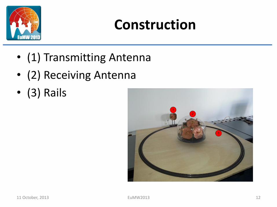
Construction
• (1) Transmitting Antenna
• (2) Receiving Antenna
• (3) Rails
11 October, 2013 EuMW2013 12

Devices
• Spectrum Analyzer: Rhode & Schwarz, FSL
1450 MHz – 1550 MHz
100 KHz BW
RMS detector
• Signal Generator: Rhode & Schwarz, SMIQ
Frequency: 1500 MHz
Amplitude: -30 dBm
• Scanning Software: PMSE Occupation Recorder
11 October, 2013 EuMW2013 13

Setup
• Software switches the 9 Antennas
• Angle Step: 9.5 °
• Measurement Time: 5 min. / step
• Polarization of transmitting Antenna: Horizontal
11 October, 2013 EuMW2013 14

RESULTS
11 October, 2013 EuMW2013 15

Measurement Results 0°
11 October, 2013 EuMW2013 16

Measurement Results 90°
11 October, 2013 EuMW2013 17
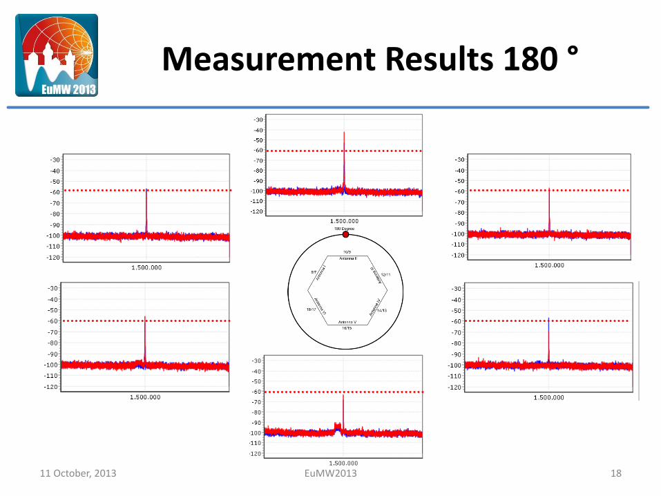
Measurement Results 180 °
11 October, 2013 EuMW2013 18

Interpretation
• Highest peak at the antenna element where the transmitter is located
• Rude angle estimation possible
• Further methods are needed to get more exact estimations
11 October, 2013 EuMW2013 19

CONCLUSION & OUTLOOK
11 October, 2013 EuMW2013 20

Conclusion
• Antenna with switchable antenna elements and simple switching hardware
• First approach for observing the spatial spectrum use has been showed
• Rude AoA-estimation is possible by amplitude scanning
11 October, 2013 EuMW2013 21

Outlook
• Develop AoA-Algorithm
• Built more antennas to exactly locate the PMSE device
• New antennas are easy to build up:
Dual polarized Patch antenna
300 MHz Bandwidth (S11 < -10 dB)
Horizontal to vertical decupling of < -30 dB
11 October, 2013 EuMW2013 22

THANK YOU FOR LISTENING
QUESTIONS?
11 October, 2013 EuMW2013 23