Embed Size (px)
Citation preview
Measurement and prediction of pressure dropin two-phase micro-channel heat sinks
Weilin Qu, Issam Mudawar *
Boiling and Two-phase Flow Laboratory, School of Mechanical Engineering, Purdue University, West Lafayette, IN 47907, USA
Received 18 October 2002; received in revised form 13 January 2003
Abstract
This study explores hydrodynamic instability and pressure drop in a water-cooled two-phase micro-channel heat
sink containing 21 parallel 231� 713 lm micro-channels. Two types of two-phase hydrodynamic instability were
identified: severe pressure drop oscillation and mild parallel channel instability. It is shown the severe pressure drop
oscillation, which can trigger pre-mature critical heat flux, can be eliminated simply by throttling the flow upstream of
the heat sink. Different methods for predicting two-phase pressure drop are assessed for suitability to micro-channel
heat-sink design. First, generalized two-phase pressure drop correlations are examined, which include 10 correlations
developed for both macro- and mini/micro-channels. A new correlation incorporating the effects of both channel size
and coolant mass velocity is proposed which shows better accuracy than prior correlations. The second method consists
of a theoretical annular two-phase flow model which, aside from excellent predictive capability, possesses the unique
attributes of providing a detailed description of the various transport processes occurring in the micro-channel, as well
as fundamental appeal and broader application range than correlations.
� 2003 Elsevier Science Ltd. All rights reserved.
Keywords: Micro-channel; Two-phase flow; Boiling; Pressure drop
1. Introduction
The unique attributes of low thermal resistance,
compact dimensions, small coolant inventory, low flow
rate requirements, and fairly uniform stream-wise tem-
perature render two-phase micro-channel heat sinks a
prime contender for thermal management of high-power-
density electronic components in many cutting-edge
computer, aerospace and medical applications. Imple-
mentation of this powerful cooling scheme is hindered
by limited understanding of the momentum and thermal
transport characteristics of two-phase micro-channels.
Due to the small hydraulic diameter used in two-
phase micro-channel heat sinks, 10–1000 lm, excessive
pressure drop is always a concern, since these devices are
typically used with miniature pumps with limited
pumping power capability. Another practical concern is
pressure oscillation due to hydrodynamic instabilities.
Instabilities must therefore be identified and prevented
to ensure safe operation and predictable cooling per-
formance.
A few published studies discuss pressure drop and
hydrodynamic instability of flow boiling in mini/micro-
channels. Flow boiling pressure drop of refrigerant
R-113 in both mini-channel (2.54 mm i.d.) and micro-
channel (510 lm i.d.) heat sinks was examined by
Bowers and Mudawar [1–3]. They adopted the homo-
genous equilibrium model to evaluate pressure drop in
the two-phase region with good accuracy. Tran et al. [4]
studied flow boiling pressure drop of three refrigerants
(R-124a, R-12, and R-113) in single tubes (2.46 and 2.92
mm i.d.) and a single rectangular channel (4:06� 1:7mm2). They evaluated the accelerational component of
pressure drop using a separated flow model incorpo-
rating Zivi�s void fraction correlation [5] and tested five
*Corresponding author. Tel.: +765-494-5705; fax: +765-494-
0539.
E-mail address: [email protected] (I. Mudawar).
0017-9310/03/$ - see front matter � 2003 Elsevier Science Ltd. All rights reserved.
doi:10.1016/S0017-9310(03)00044-9
International Journal of Heat and Mass Transfer 46 (2003) 2737–2753
www.elsevier.com/locate/ijhmt

Nomenclature
Ac vapor core cross-sectional area
Ach micro-channel cross-sectional area
Ap1, Ap2 plenum cross-sectional area
At planform area of heat sink�s top surface
Bo boiling number
C Martinelli–Chisholm constant
CEf liquid droplet concentration in vapor core
cP specific heat at constant pressure
D deposition rate
dh hydraulic diameter of micro-channel
dh;c hydraulic diameter of vapor core
f friction factor
fapp apparent friction factor for developing
single-phase liquid flow
ff friction factor based on local liquid flow rate
ffo friction factor based on total flow rate as
liquid
Fr Froude number
G mass velocity in micro-channel
Gp1, Gp2 mass velocity in plenums
h enthalpy
Hch height of micro-channel
hfg latent heat of vaporization
jg vapor superficial velocity
k deposition mass transfer coefficient
Kc1, Kc2 contraction loss coefficient
Ke1, Ke2 expansion recovery coefficient
L length of micro-channel
Lþsp;d non-dimensional length of single-phase de-
veloping sub-region
_mm mass flow rate per micro-channel
N number of micro-channels in heat sink
P pressure
Pc vapor core perimeter
Pch micro-channel perimeter
PW total electrical power input to heat sink�scartridge heaters
DP pressure drop
DPc1, DPc2 contraction pressure loss
DPe1, DPe2 expansion pressure recovery
DPtp;a accelerational component of two-phase
pressure drop
DPtp;f frictional component of two-phase pressure
drop
q00eff effective heat flux based on heat sink�s top
planform area
Re Reynolds number
Ref Reynolds number based on local liquid flow
Refo Reynolds number based on total flow as
liquid
Reg Reynolds number based on local vapor flow
t time
T temperature
Tsat saturation temperature
uc mean vapor core velocity
uf local velocity in liquid film
ui interfacial velocity
v specific volume
vfg specific volume difference between saturated
vapor and saturated liquid
W width of heat sink
Wch width of micro-channel
We Weber number
xe thermodynamic equilibrium quality
Xvt Martinelli parameter based on laminar liquid–
turbulent vapor flow
Xvv Martinelli parameter based on laminar liquid–
laminar vapor flow
y distance from channel wall
z axial coordinate
Greek symbols
a void fraction
b aspect ratio of micro-channel
bc aspect ratio of vapor core
Cd deposition mass transfer rate per unit micro-
channel length
Cfg evaporation mass transfer rate per unit
micro-channel length
d liquid film thickness
l viscosity
q density
r surface tension
s shear stress
/2f two-phase frictional multiplier based on
local liquid flow rate
/2fo two-phase frictional multiplier based on
total flow considered as liquid
Subscripts
0 onset of annular flow
a accelerational
c vapor core; contraction
e expansion
Ef liquid droplet
exp experimental (measured)
f liquid; frictional
Ff liquid film
g vapor
H homogeneous
i interface
in test module inlet
out test module outlet
p1, p2 deep, shallow plenum
pred predicted
2738 W. Qu, I. Mudawar / International Journal of Heat and Mass Transfer 46 (2003) 2737–2753

different macro-channel correlations for the frictional
component. Significant deviation between predictions
and experimental data led them to develop a new fric-
tional pressure drop correlation that enhanced agree-
ment with the data. Lee and Lee [6] studied flow boiling
pressure drop of R-113 in single rectangular channels of
20 mm width and 0.4, 1 and 2 mm height. Zivi�s void
fraction correlation was also used to determine the ac-
celerational component of pressure drop. Several prior
correlations developed for both macro- and mini/micro-
channels were tested for frictional component prediction.
Most showed large discrepancy except for a modified
Lockhart–Martinelli correlation proposed earlier by the
same authors [7]. Yu et al. [8] studied flow boiling
pressure drop of water in a single tube (2.98 mm i.d.),
but did not consider the accelerational pressure drop.
They proposed a modified Lockhart–Martinelli corre-
lation to improve their model�s predictive capability.
Two-phase hydrodynamic instabilities in parallel
mini/micro-channels were addressed by Kandlikar et al.
[9] and Hetsroni et al. [10]. Kandlikar et al. studied
water flow boiling in a test section containing six parallel
1� 1 mm2 channels. Both inlet and outlet pressures
fluctuated with large amplitude, and the magnitude of
fluctuation was sometimes so severe that negative pres-
sure drops were measured across the test section. Hets-
roni et al. conducted experiments with dielectric liquid
Vertel XF in a micro-channel heat sink containing 21
parallel triangular micro-channels having a base di-
mension of 250 lm. The flow in individual micro-
channels alternated between single-phase liquid and
elongated vapor bubbles. The amplitude of pressure
drop fluctuation increased significantly with increasing
heat flux.
The aforementioned studies provide valuable insight
into the transport characteristics of two-phase micro-
channel heat sinks. However, designers of such devices
are faced with a host of unique issues which complicate
the implementation of existing knowledge. These include
high-aspect-ratio rectangular flow passages, three rather
than four-sided heating, parallel channel interactions,
and the use of water instead of refrigerants as working
fluid. These features have become a standard for devices
that are recommended for many high-heat-flux cooling
situations, yet virtually no data presently exist which
combine all these features.
This study is an investigation into pressure drop and
hydrodynamic instability of a water-cooled two-phase
micro-channel heat sink. The primary objectives of this
study are to (1) provide a new database for the afore-
mentioned micro-channel heat sink geometry, (2) ex-
plore different forms of hydrodynamic instability in
parallel two-phase micro-channels as well as means of
eliminating severe forms of instability, (3) assess the
accuracy of previous correlations at predicting pressure
drop characteristics, and (4) develop new predictive
tools, both empirical and theoretical, for accurate pre-
diction of heat-sink pressure drop.
2. Experimental apparatus and procedure
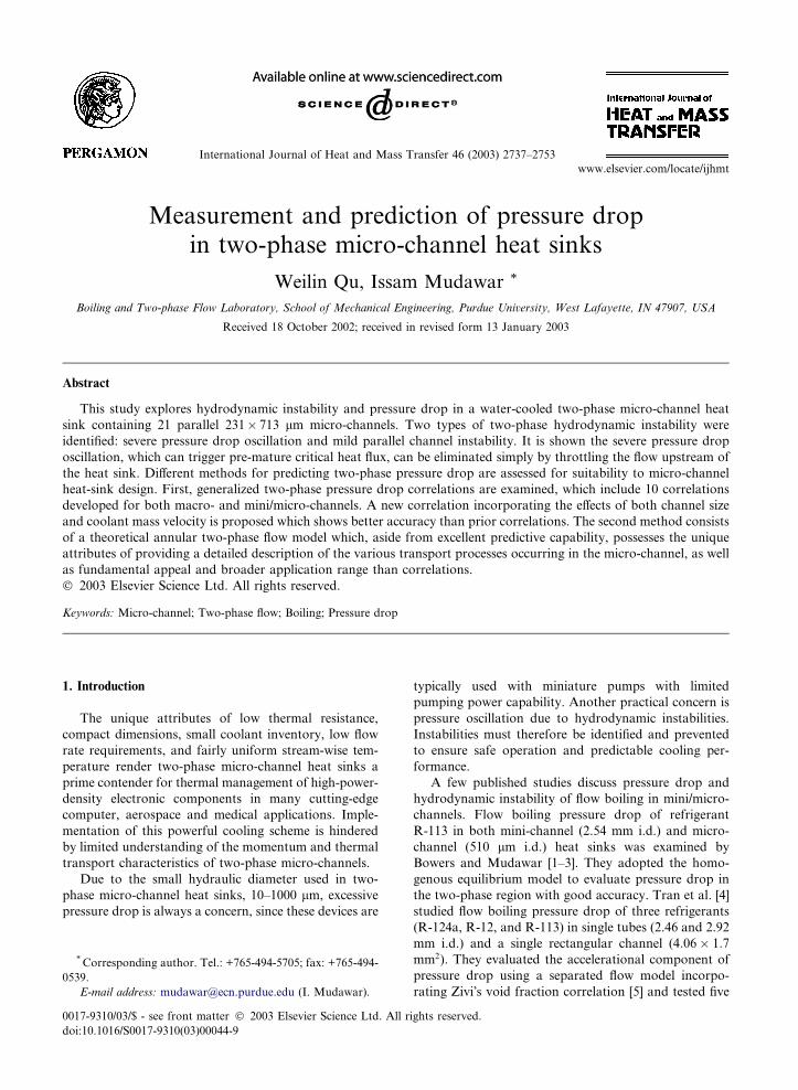
Fig. 1 shows a schematic of the two-phase coolant-
conditioning loop which delivered deionized water to the
test module. A constant temperature bath was employed
to adjust the test module�s inlet temperature, while a
condenser situated downstream from the module re-
turned any vapor exiting the module to liquid state. A
control valve was situated upstream of the module
mainly for flow control, and a second valve downstream
to regulate outlet pressure.
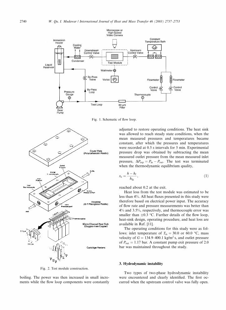
Aside from the heat sink itself, the test module con-
sisted of housing, cover plate, and 12 cartridge heaters,
as illustrated in Fig. 2. Viewed from above, the heat sink
measured 1.0 cm in width and 4.48 cm in length. The
micro-channels were formed by cutting 21 of 231-lmwide and 712-lm deep micro-slots into the heat sink�stop surface. Four thermocouples were inserted beneath
the top surface to measure the heat sink�s stream-wise
temperature distribution. The underside of the heat sink
was bored to accept 12 cartridge heaters. The housing
contained deep and shallow plenums both upstream and
downstream of the micro-channels to ensure even flow
distribution. Two absolute pressure transducers were
connected to the deep plenums via pressure taps to
measure the inlet and outlet pressures. Also located in
the deep plenums were two thermocouples for inlet and
outlet temperature measurement. The micro-channels
were formed by bolting the cover plate atop the housing.
After the test module was assembled, multiple layers of
ceramic fiber were wrapped around the heat sink to re-
duce heat loss to the ambient. An HP data acquisition
system interfaced to a PC was employed to record sig-
nals from the pressure transducers and thermocouples.
Water in the reservoir was initially deaerated by
vigorous boiling for about 1 h to force any dissolved
gases to escape to the ambient. The flow loop compo-
nents were then adjusted to yield the desired operating
conditions. After the flow became stable, the heater
power input was adjusted to a value below incipient
sp single-phase
sp,d single-phase developing sub-region
sp,f single-phase fully developed sub-region
tp two-phase
W. Qu, I. Mudawar / International Journal of Heat and Mass Transfer 46 (2003) 2737–2753 2739
boiling. The power was then increased in small incre-
ments while the flow loop components were constantly
adjusted to restore operating conditions. The heat sink
was allowed to reach steady state conditions, when the
mean measured pressures and temperatures became
constant, after which the pressures and temperatures
were recorded at 0.5 s intervals for 5 min. Experimental
pressure drop was obtained by subtracting the mean
measured outlet pressure from the mean measured inlet
pressure, DPexp ¼ Pin � Pout. The test was terminated
when the thermodynamic equilibrium quality,
xe ¼h � hfhfg
; ð1Þ
reached about 0.2 at the exit.
Heat loss from the test module was estimated to be
less than 4%. All heat fluxes presented in this study were
therefore based on electrical power input. The accuracy
of flow rate and pressure measurements was better than
4% and 3.5%, respectively, and thermocouple error was
smaller than �0.3 �C. Further details of the flow loop,
heat-sink design, operating procedure, and heat loss are
available in Ref. [11].
The operating conditions for this study were as fol-
lows: inlet temperature of Tin ¼ 30:0 or 60.0 �C, mass
velocity of G ¼ 134:9–400.1 kg/m2 s, and outlet pressure
of Pout ¼ 1:17 bar. A constant pump exit pressure of 2.0
bar was maintained throughout the study.
3. Hydrodynamic instability
Two types of two-phase hydrodynamic instability
were encountered and clearly identified. The first oc-
curred when the upstream control valve was fully open.
Fig. 2. Test module construction.
Fig. 1. Schematic of flow loop.
2740 W. Qu, I. Mudawar / International Journal of Heat and Mass Transfer 46 (2003) 2737–2753
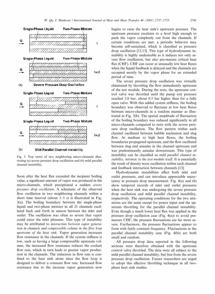
Soon after the heat flux exceeded the incipient boiling
value, a significant amount of vapor was produced in the
micro-channels, which precipitated a sudden severe
pressure drop oscillation. A schematic of the observed
flow oscillation in two neighboring channels within a
short time interval (about 1–5 s) is illustrated in Fig.
3(a). The boiling boundary between the single-phase
liquid and two-phase mixture in all 21 channels oscil-
lated back and forth in unison between the inlet and
outlet. The oscillation was often so severe that vapor
could enter the inlet plenums. This type of instability
may be attributed to interaction between vapor genera-
tion in channels and compressible volume in the flow loop
upstream of the heat sink. Vapor generation increases
flow resistance in the channels. If the system stiffness is
low, such as having a large compressible upstream vol-
ume, the increased flow resistance reduces the coolant
flow rate, which in turn leads to greater vapor produc-
tion in the channels. The reduction in flow rate is con-
fined to the heat sink alone since the flow loop is
designed to deliver a constant flow rate. Increased flow
resistance due to the increase vapor generation now
begins to raise the heat sink�s upstream pressure. The
upstream pressure escalates to a level high enough to
push the vapor completely out from the channels. If
certain conditions are met, a periodic behavior may
become self-sustained, which is classified as pressure
drop oscillation [12,13]. This type of hydrodynamic in-
stability is highly undesirable as it induces not only se-
vere flow oscillation, but also pre-mature critical heat
flux (CHF). CHF can occur at unusually low heat fluxes
when the liquid feedback is delayed and the channels are
occupied mostly by the vapor phase for an extended
period of time.
The severe pressure drop oscillation was virtually
eliminated by throttling the flow immediately upstream
of the test module. During the tests, the upstream con-
trol valve was throttled until the pump exit pressure
reached 2.0 bar, about 0.5 bar higher than for a fully
open valve. With this added system stiffness, the boiling
boundary was observed to fluctuate at low heat fluxes
between micro-channels in a random manner as illus-
trated in Fig. 3(b). The spatial amplitude of fluctuation
of the boiling boundary was reduced significantly in all
micro-channels compared to tests with the severe pres-
sure drop oscillation. The flow pattern within each
channel oscillated between bubble nucleation and slug
flow. At medium to high heat fluxes, the boiling
boundaries propagated upstream, and the flow oscillated
between slug and annular in the channel upstream and
was predominantly annular downstream. This type of
instability can be classified as mild parallel channel in-
stability, intrinsic to the test module itself. It is essentially
the result of density wave oscillation within each channel
and feedback interaction between channels [13].
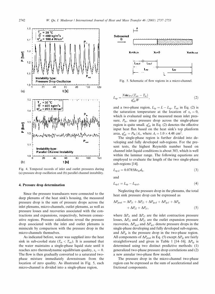
Hydrodynamic instabilities affect both inlet and
outlet pressures, and can introduce appreciable uncer-
tainty in pressure drop measurement. Fig. 4(a) and (b)
show temporal records of inlet and outlet pressures
when the heat sink was undergoing the severe pressure
drop oscillation and mild parallel channel instability,
respectively. The operating conditions for the two situ-
ations are the same except for power input and the up-
stream throttling for the parallel channel instability.
Even though a much lower heat flux was applied in the
pressure drop oscillation case (Fig. 4(a)) to avoid pre-
mature CHF, the pressure fluctuations are far more se-
vere. Furthermore, the pressure fluctuations appear to
form with fairly constant frequency. Fluctuations in the
parallel channel instability case (Fig. 4(b)) are both
small and random.
All pressure drop data reported in the following
sections were therefore obtained with the upstream
control valve throttled. The data were all subject to the
mild parallel channel instability, but free from the severe
pressure drop oscillation. Future researchers are urged
to adopt this effective throttling technique in all two-
phase heat sink studies.
Fig. 3. Top views of two neighboring micro-channels illus-
trating (a) severe pressure drop oscillation and (b) mild parallel
channel instability.
W. Qu, I. Mudawar / International Journal of Heat and Mass Transfer 46 (2003) 2737–2753 2741
4. Pressure drop determination
Since the pressure transducers were connected to the
deep plenums of the heat sink�s housing, the measured
pressure drop is the sum of pressure drops across the
inlet plenums, micro-channels, outlet plenums, as well as
pressure losses and recoveries associated with the con-
tractions and expansions, respectively, between consec-
utive regions. Pressure calculations reveal the pressure
drop associated with the inlet and outlet plenums is
miniscule by comparison with the pressure drop in the
micro-channels themselves.
As indicated before, water was supplied into the heat
sink in sub-cooled state (Tin < Tsat). It is assumed that
the water maintains a single-phase liquid state until it
reaches zero thermodynamic equilibrium quality, xe ¼ 0.
The flow is then gradually converted to a saturated two-
phase mixture immediately downstream from the
location of zero quality. As illustrated in Fig. 5, each
micro-channel is divided into a single-phase region,
Lsp ¼N _mmcP;fðTsat � TinÞ
q00effW; ð2Þ
and a two-phase region, Ltp ¼ L� Lsp. Tsat in Eq. (2) is
the saturation temperature at the location of xe ¼ 0,
which is evaluated using the measured mean inlet pres-
sure, Pin, since pressure drop across the single-phase
region is quite small. q00eff in Eq. (2) denotes the effective
input heat flux based on the heat sink�s top planform
area, q00eff ¼ PW=At, where At ¼ 1.0� 4.48 cm2.
The single-phase region is further divided into de-
veloping and fully developed sub-regions. For the pre-
sent tests, the highest Reynolds number based on
channel inlet liquid conditions is about 303, which is well
within the laminar range. The following equations are
employed to evaluate the length of the two single-phase
sub-regions [14].
Lsp;d ¼ 0:0785Reindh; ð3Þ
and
Lsp;f ¼ Lsp � Lsp;d: ð4Þ
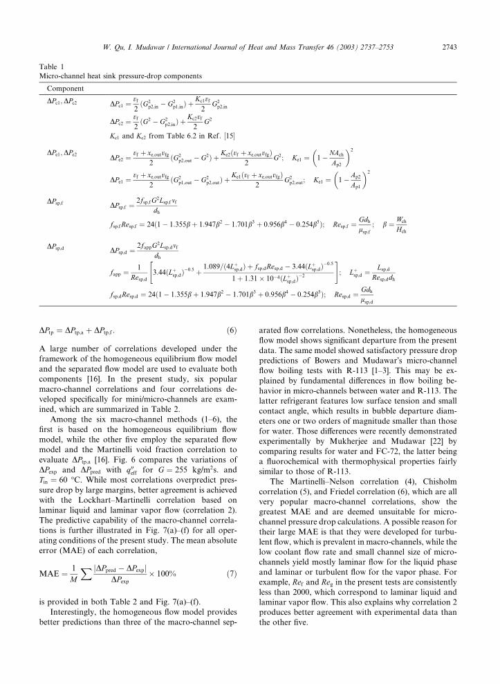
Neglecting the pressure drop in the plenums, the total
heat sink pressure drop can be expressed as
DPpred ¼ DPc1 þ DPc2 þ DPsp;d þ DPsp;f þ DPtp
þ DPe2 þ DPe1; ð5Þ
where DPc1 and DPc2 are the inlet contraction pressure
losses, DPe2 and DPe1 are the outlet expansion pressure
recoveries, DPsp;d and DPsp;f denote pressure drops in the
single-phase developing and fully developed sub-regions,
and DPtp is the pressure drop in the two-phase region.
All components of DPpred in Eq. (5) except DPtp are fairly
straightforward and given in Table 1 [14–16]. DPtp is
determined using two distinct predictive methods: (1)
generalized two-phase pressure drop correlations and (2)
a new annular two-phase flow model.
The pressure drop in the micro-channel two-phase
region can be expressed as the sum of accelerational and
frictional components.
Fig. 4. Temporal records of inlet and outlet pressures during
(a) pressure drop oscillation and (b) parallel channel instability.
Fig. 5. Schematic of flow regions in a micro-channel.
2742 W. Qu, I. Mudawar / International Journal of Heat and Mass Transfer 46 (2003) 2737–2753
DPtp ¼ DPtp;a þ DPtp;f : ð6Þ
A large number of correlations developed under the
framework of the homogeneous equilibrium flow model
and the separated flow model are used to evaluate both
components [16]. In the present study, six popular
macro-channel correlations and four correlations de-
veloped specifically for mini/micro-channels are exam-
ined, which are summarized in Table 2.
Among the six macro-channel methods (1–6), the
first is based on the homogeneous equilibrium flow
model, while the other five employ the separated flow
model and the Martinelli void fraction correlation to
evaluate DPtp;a [16]. Fig. 6 compares the variations of
DPexp and DPpred with q00eff for G ¼ 255 kg/m2s. and
Tin ¼ 60 �C. While most correlations overpredict pres-
sure drop by large margins, better agreement is achieved
with the Lockhart–Martinelli correlation based on
laminar liquid and laminar vapor flow (correlation 2).
The predictive capability of the macro-channel correla-
tions is further illustrated in Fig. 7(a)–(f) for all oper-
ating conditions of the present study. The mean absolute
error (MAE) of each correlation,
MAE ¼ 1
M
X jDPpred � DPexpjDPexp
� 100% ð7Þ
is provided in both Table 2 and Fig. 7(a)–(f).
Interestingly, the homogeneous flow model provides
better predictions than three of the macro-channel sep-
arated flow correlations. Nonetheless, the homogeneous
flow model shows significant departure from the present
data. The same model showed satisfactory pressure drop
predictions of Bowers and Mudawar�s micro-channel
flow boiling tests with R-113 [1–3]. This may be ex-
plained by fundamental differences in flow boiling be-
havior in micro-channels between water and R-113. The
latter refrigerant features low surface tension and small
contact angle, which results in bubble departure diam-
eters one or two orders of magnitude smaller than those
for water. Those differences were recently demonstrated
experimentally by Mukherjee and Mudawar [22] by
comparing results for water and FC-72, the latter being
a fluorochemical with thermophysical properties fairly
similar to those of R-113.
The Martinelli–Nelson correlation (4), Chisholm
correlation (5), and Friedel correlation (6), which are all
very popular macro-channel correlations, show the
greatest MAE and are deemed unsuitable for micro-
channel pressure drop calculations. A possible reason for
their large MAE is that they were developed for turbu-
lent flow, which is prevalent in macro-channels, while the
low coolant flow rate and small channel size of micro-
channels yield mostly laminar flow for the liquid phase
and laminar or turbulent flow for the vapor phase. For
example, Ref and Reg in the present tests are consistently
less than 2000, which correspond to laminar liquid and
laminar vapor flow. This also explains why correlation 2
produces better agreement with experimental data than
the other five.
Table 1
Micro-channel heat sink pressure-drop components
Component
DPc1;DPc2 DPc1 ¼vf2ðG2
p2;in � G2p1;inÞ þ
Kc1vf2
G2p2;in
DPc2 ¼vf2ðG2 � G2
p2;inÞ þKc2vf2
G2
Kc1 and Kc2 from Table 6:2 in Ref : ½15�
DPe1;DPe2DPe2 ¼
vf þ xe;outvfg2
ðG2p2;out � G2Þ þ Ke2ðvf þ xe;outvfgÞ
2G2; Ke1 ¼ 1
�� NAch
Ap2
�2
DPe1 ¼vf þ xe;outvfg
2ðG2
p1;out � G2p2;outÞ þ
Ke1ðvf þ xe;outvfgÞ2
G2p2;out; Ke1 ¼ 1
�� Ap2
Ap1
�2
DPsp;f DPsp;f ¼2fsp;fG2Lsp;fmf
dh
fsp;fResp;f ¼ 24ð1� 1:355b þ 1:947b2 � 1:701b3 þ 0:956b4 � 0:254b5Þ; Resp;f ¼Gdhlsp;f
; b ¼ Wch
Hch
DPsp;d DPsp;d ¼2fappG2Lsp;dmf
dh
fapp ¼1
Resp;d3:44ðLþ
sp;d�0:5
"þ1:089=ð4Lþ
sp;dÞ þ fsp;dResp;d � 3:44ðLþsp;dÞ
�0:5
1þ 1:31� 10�4ðLþsp;dÞ
�2
#; Lþ
sp;d ¼Lsp;d
Resp;ddh
fsp;dResp;d ¼ 24ð1� 1:355b þ 1:947b2 � 1:701b3 þ 0:956b4 � 0:254b5Þ; Resp;d ¼Gdhlsp;d
W. Qu, I. Mudawar / International Journal of Heat and Mass Transfer 46 (2003) 2737–2753 2743

Table 2
Generalized two-phase pressure-drop correlations
Correlation
(or model)
Reference Frictional component, DPtp;f Accelerational component, DPtp;a MAE (%)
1 Homogeneous model [16]DPtp;f ¼
2ftpG2Ltpvfdh
1
�þ xe;out
2
vfgvf
� ��; ftp ¼ 0:003
DPtp;a ¼ G2vfxe;out 89.2
2 Lockhart–Martinelli
(laminar liquid–laminar
vapor) [17,18]
DPtp;f ¼Ltp
xe;out
Z xe;out
0
2ffG2ð1� xeÞ2vfdh
/2f dxe DPtp;a ¼ G2vf
x2e;outaout
vgvf
� �"þ ð1� xe;outÞ2
1� aout
� 1
#28.6
ffRef ¼ 24ð1� 1:355b þ 1:947b2 � 1:701b3 þ 0:956b4 � 0:254b5Þ;
Ref ¼Gð1� xeÞdh
lf
aout ¼ 1� 1ffiffiffiffiffiffiffiffiffiffiffiffiffiffiffiffiffiffiffiffiffiffiffiffiffiffiffiffiffiffiffiffi1þ 20
Xvv;outþ 1
X 2vv;out
q
/2f ¼ 1þ C
Xvv
þ 1
X 2vv
; C ¼ 5;
Xvv ¼lf
lg
!0:5
1� xexe
� �0:5 vfvg
� �0:5
3 Lockhart Martinelli
(laminar liquid–turbulent
vapor) [17,18]
DPtp;f ¼Ltp
xe;out
Z xe;out
0
2ffG2ð1� xeÞ2vfdh
/2f dxe DPtp;a ¼ G2vf
x2e;outaout
vgvf
� �"þ ð1� xe;outÞ2
1� aout
� 1
#44.6
/2f ¼ 1þ C
Xvt
þ 1
X 2vt
; C ¼ 12;
Xvt ¼ffRe0:25g
0:079
!0:5
1� xexe
� �vfvg
� �0:5
; Reg ¼Gxedh
lg
aout ¼ 1� 1ffiffiffiffiffiffiffiffiffiffiffiffiffiffiffiffiffiffiffiffiffiffiffiffiffiffiffiffiffiffiffi1þ 20
Xvt;outþ 1
X 2vt;out
q
4 Martinelli–Nelson [19]DPtp;f ¼
2ffoG2Ltpvfdh
r1ðxe;out; PÞ; r1ðxe;out; P Þ
from Fig: 4 in Ref : ½19�
DPtp;a ¼ G2vf r2ðxe;out; PÞ; r2ðxe;out; P Þfrom Fig: 6 in Ref : ½19�
165.5
ffoRefo ¼ 24ð1� 1:355b þ 1:947b2 � 1:701b3 þ 0:956b4 � 0:254b5Þ;Refo ¼
Gdhlf
5 Chisholm [20]DPtp;f ¼
2ffoG2vfdh
Ltp
xe;out
Z xe;out
0
/2fo dxe DPtp;a ¼ G2vf
x2e;outaout
vgvf
� �"þ ð1� xe;outÞ2
1� aout
� 1
#378.4
/2fo ¼ 1þ ðC2 � 1Þ½Bx0:5e ð1� xeÞ0:5 þ xe�;
C ¼ vgvf
� �0:5 lg
lf
� �0:5
; B from Table 2 in Ref : ½20�
aout ¼ 1� 1ffiffiffiffiffiffiffiffiffiffiffiffiffiffiffiffiffiffiffiffiffiffiffiffiffiffiffiffiffiffiffiffi1þ 20
Xvv;outþ 1
X 2vv;out
q
2744
W.Qu,I.Mudawar/InternationalJournalofHeatandMassTransfer46(2003)2737–2753

6 Friedel [16]DPtp;f ¼
2ffoG2vfdh
Ltp
xe;out
Z xe;out
0
/2fo dxe DPtp;a ¼ G2vf
x2e;outaout
vgvf
� �"þ ð1� xe;outÞ2
1� aout
� 1
#355.0
/2fo ¼ A1 þ
3:34A2A3
Fr0:045H We0:035H
;
A1 ¼ ð1� xeÞ2 þ x2evgvf
� �lg
lf
� �; A2 ¼ x0:78e ð1� xeÞ0:224
aout ¼ 1� 1ffiffiffiffiffiffiffiffiffiffiffiffiffiffiffiffiffiffiffiffiffiffiffiffiffiffiffiffiffiffiffiffi1þ 20
Xvv;outþ 1
X 2vv;out
q
A3 ¼vgvf
� �0:91 lg
lf
� �0:19
1
��
lg
lf
�0:7
;
FrH ¼ G2
gdhq2H
; WeH ¼ G2dhqHr
; qH ¼ 1
xevg þ ð1� xeÞvf
7 Mishima and Hibiki
[21]DPtp;f ¼
Ltp
xe;out
Z xe;out
0
2ffG2ð1� xeÞ2vfdh
/2f dxe DPtp;a ¼ G2vf
x2e;outaout
vgvf
� �"þ ð1� xe;outÞ2
1� aout
� 1
#13.9
/2f ¼ 1þ C
Xvv
þ 1
X 2vv
; C ¼ 21½1� expð�0:319� 103dhÞ�;
Xvv ¼lf
lg
!0:5
1� xexe
� �0:5 vfvg
� �0:5
aout ¼1
1þ 1�xe;outxe;out
�vfvg
�2=3
8 Tran et al. [4]DPtp;f ¼
2ffoG2vfdh
Ltp
xe;out
Z xe;out
0
/2fo dxe DPtp;a ¼ G2vf
x2e;outaout
vgvf
� �"þ ð1� xe;outÞ2
1� aout
� 1
#828.3
/2fo ¼ 1þ ð4:3C2 � 1Þ½Nconfx0:875e ð1� xeÞ0:875 þ x1:75e � aout ¼
1
1þ 1�xe;outxe;out
�vfvg
�2=3
C ¼ vgvf
� �0:5 lg
lf
� �0:5
; Nconf ¼r
gðqf � qgÞ
" #0:5=dh
9 Lee and Lee [6]DPtp;f ¼
Ltp
xe;out
Z xe;out
0
2ffG2ð1� xeÞ2vfdh
/2f dxe DPtp;a ¼ G2vf
x2e;outaout
vgvf
� �"þ ð1� xe;outÞ2
1� aout
� 1
#19.1
/2f ¼ 1þ C
Xvt
þ 1
X 2vt
; C ¼ 6:185� 10�2Re0:726fo ;
Xvt ¼ffRe0:25g
0:079
!0:5
1� xexe
� �vfvg
� �0:5
aout ¼1
1þ 1�xe;outxe;out
�vfvg
�2=3
(continued on next page)
W.Qu,I.Mudawar/InternationalJournalofHeatandMassTransfer46(2003)2737–2753
2745

The four remaining correlations in Table 2 (7–10)
were developed from mini/micro-channel pressure drop
data, and are all based on the separated flow model and
employ the Zivi void fraction correlation [5] to evaluate
DPtp;a. Figs. 8 and 9(a)–(d), compare DPpred to DPexp for
these correlations. The Tran et al. correlation (8) is ex-
cluded from Fig. 8 because it predicts unusually small
values compared to the data.
The Mishima and Hibiki�s correlation (7) is based on
the combination of laminar liquid and laminar vapor
flow, and accounts for channel size effect by incorpo-
rating channel hydraulic diameter in the Martinelli–
Chisholm constant C [21]. With a MAE of 13.9%, this
correlation yields the most accurate predictions of all
previous correlations. The Tran et al. correlation (8), on
the other hand, adopts the turbulent liquid and turbu-
lent vapor flow combination [4], which may explain its
unusually large MAE. Both the Lee and Lee correlation
(9) and Yu et al. correlation (10) utilize the combination
of laminar liquid and turbulent vapor flow. In the Lee
and Lee correlation, the liquid Reynolds number is in-
corporated into the Martinelli–Chisholm constant C to
reflect the effects of both channel size and coolant flow
rate [6]. The Lee and Lee correlation provides reason-
ably accurate predictions with a MAE of 19.1%. The Yu
et al. correlation underpredicts the experimental data by
a relatively large margin.
In an effort to improve predictive accuracy, the au-
thors of the present study modified the Mishima and
Hibiki correlation by incorporating a mass velocity
term. This new correlation is listed as correlation 11 in
Table 2. Fig. 10(a) and (b) show the effectiveness of the
new correlation at predicting the pressure drop data.
While its MAE is only slightly better than the Mishima
and Hibiki correlation (12.4% versus 13.9%), the newTable
2(continued)
Correlation
(ormodel)
Reference
Frictionalcomponent,
DP t
p;f
Accelerationalcomponent,
DP t
p;a
MAE
(%)
10
Yuet
al.[8]
DP t
p;f¼
L tp
x e;out
Z x e;out
0
2f fG
2ð1
�x eÞ2v f
d h/
2 fdx e
DP t
p;a¼
G2v f
x2 e;out
a out
v g v f��
"þð1
�x e
;outÞ2
1�
a out
�1
#48.0
/2 f¼
1
X1:9
vt
;Xvt¼
f fRe0
:2g
0:046
! 0:5
1�
x ex e
��
v f v g�� 0:5
a out¼
1
1þ
1�x e
;out
x e;out
� v f v g
� 2=311
QuandMudawar
(presentstudy)
DP t
p;f¼
L tp
x e;out
Z x e;out
0
2f fG
2ð1
�x eÞ2v f
d h/
2 fdx e
DP t
p;a¼
G2v f
x2 e;out
a out
v g v f��
"þð1
�x e
;outÞ2
1�
a out
�1
#12.4
/2 f¼
1þ
C Xvv
þ1 X2 vv
a out¼
1
1þ
1�x e
;out
x e;out
� v f v g
� 2=3
C¼
21½1�expð�
0:319�103d hÞ�ð
0:00418Gþ0:0613Þ;
Xvv¼
lf
lg ! 0:5
1�
x ex e
�� 0:5
v f v g�� 0:5
Fig. 6. Comparison of pressure drop data with macro-channel
correlation predictions for Tin ¼ 60 �C and G ¼ 255 kg/m2s.
2746 W. Qu, I. Mudawar / International Journal of Heat and Mass Transfer 46 (2003) 2737–2753

correlation is recommended because it accounts for the
effects of both channel size and coolant mass velocity.
5. Annular two-phase flow model
In a previous paper by the present authors [11], an
annular two-phase flow model was developed, which is
specifically tailored to water-cooled micro-channel heat
sinks. The model incorporates the unique features of
micro-channel flow boiling and is capable of accurately
predicting the saturated boiling heat transfer coefficient.
In the present paper, the annular two-phase flow model
is used to evaluate DPtp.
The physical basis for the model lies in identification
of annular flow as the dominant pattern at moderate to
high heat fluxes. Fig. 11(a) illustrates the hydrodynamic
characteristics of the annular flow in a micro-channel.
The vapor phase flows along the channel center as a
continuous vapor core. A portion of the liquid phase
Fig. 7. Comparison of pressure drop data with predictions of (a) homogeneous equilibrium flow model [16], and macro-channel
correlations of (b) Lockhart–Martinelli (laminar liquid–laminar vapor) [17,18], (c) Lockhart–Martinelli (laminar liquid–turbulent
vapor) [17,18], (d) Martinelli–Nelson [19], (e) Chisholm [20], and (f) Friedel [16].
W. Qu, I. Mudawar / International Journal of Heat and Mass Transfer 46 (2003) 2737–2753 2747

flows as a thin film along the channel wall, while the
other portion is entrained in the vapor core as liquid
droplets. A simplified representation of the annular flow
pattern is given in Fig. 11(b). The thickness of the an-
nular liquid film is assumed to be uniform along the
channel circumference, and small compared to the hy-
draulic diameter. The interface between liquid film and
vapor core is fairly smooth due to strong surface tension
effects in micro-channels. Mass is exchanged between the
liquid film and vapor core by interfacial evaporation and
droplet deposition. Evaporation occurs only at the in-
terface, since the entrained droplets have a short resi-
dence time in a micro-channel and are remote from the
heated wall. Entrainment of liquid droplets into the
vapor core is assumed to take place entirely at the onset
of annular flow regime development. Cfg and Cd in Fig.
11(b) denote, respectively, the evaporation and deposi-
tion mass transfer rates per unit channel length.
The primary parameters of annular flow model are
the liquid film mass flow rate, _mmFf , liquid film thickness,
d, pressure gradient, �ðdP=dzÞ, and interfacial shear
stress, si. Equations relating these parameters are es-
tablished by applying fundamental conservation equa-
tions to both the liquid film and vapor core and
summarized in Table 3. A brief overview on the model
development is given below; further details are left to
Ref. [11] for brevity.
Fig. 8. Comparison of pressure drop data with mini/micro-
channel correlation predictions for Tin ¼ 60 �C and G ¼ 255 kg/
m2s.
Fig. 9. Comparison of pressure drop data with predictions of mini/micro-channel correlations of (a) Mishima and Hibiki [21], (b) Tran
et al. [4], (c) Lee and Lee [6], and (d) Yu et al. [8].
2748 W. Qu, I. Mudawar / International Journal of Heat and Mass Transfer 46 (2003) 2737–2753

5.1. Mass conservation
Mass transfer between the liquid film and vapor core
can be represented by the following mass conservation
equations,
d _mmFf
dz¼ �Cfg þ Cd; ð8Þ
d _mmEf
dz¼ �Cd; ð9Þ
and
d _mmg
dz¼ Cfg; ð10Þ
which are included in Section I of Table 3. Cfg and Cd
can be evaluated by using energy conservation and de-
position relations listed in Table 3. The deposition re-
lation incorporates a mass transfer coefficient, k, which
is evaluated using a correlation proposed by the authors
specifically for micro-channel heat sinks [11],
kjg
¼ 47:8BoCqg
!�0:147
: ð11Þ
Once Cfg and Cd are determined, local values of _mmFf , _mmEf ,
and _mmg can be obtained by integrating Eqs. (8)–(10) along
the stream-wise direction. Appropriate boundary con-
ditions are required for this integration, which involve
location of the onset of annular flow and the initial mass
flow rate of each portion at that location. The location of
the onset of annular flow is determined from a criterion
for transition to annular flow by Taitel and Duckler
[16,23]. According to the criterion, the Martinelli pa-
rameter has a constant value at the transition point.
Xvv0 ¼ 1:6: ð12Þ
The initial liquid droplet mass flow rate _mmEf0 is given by
the following correlation.
_mmEf0
_mm¼ 0:951� 0:15
ffiffiffiffiffiffiffiffiffiWef0
p; ð13Þ
where Wef0 is the Weber number of water given by
Wef ¼vfG2dh
r: ð14Þ
5.2. Momentum conservation in liquid film
Momentum conservation is applied to the liquid film
using the control volume shown in Fig. 12(a). The
Fig. 10. Comparison of present correlation predictions with
pressure drop data for (a) Tin ¼ 60 �C and G ¼ 255 kg/m2s, and
(b) entire database.
Fig. 11. (a) Schematic of annular flow pattern in micro-channel
heat sink, and (b) idealized annular flow region.
W. Qu, I. Mudawar / International Journal of Heat and Mass Transfer 46 (2003) 2737–2753 2749

schematic to the left of Fig. 12(a) illustrates momen-
tum exchange along the liquid film interface, and to
the right the forces acting on the same control volume in
the stream-wise direction. Momentum conservation
yields
s ¼ ðd � yÞ�� dp
dz
�þ si �
1
Pch
ðCfgui � CducÞ: ð15Þ
The shear stress in the laminar liquid film can be
related to the local velocity gradient by
Table 3
Key equations in annular two-phase flow model
Equation
I d _mmFf
dz¼ �Cfg þ Cd;
d _mmEf
dz¼ �Cd;
d _mmg
dz¼ Cfg
Cfg ¼q00effWNhfg
; Cd ¼ DPc
D ¼ kCEf ; Pc ¼ 2½ðWch � 2dÞ þ ðHch � 2dÞ�
CEf ¼_mmEf
_mmgvg þ _mmEfvf;
kjg
¼ 47:8BoCEf
qg
!�0:147
; Bo ¼ q00effWNðWch þ 2HchÞGhfg
; jg ¼_mmg
qgAch
II�� dp
dz
�¼ 3lf
Pchqfd3_mmFf �
3
2dsi þ
3
2dPch
ðCfgui � CducÞ
ui ¼2 _mmFf
qf ðAch � AcÞ; uc ¼
_mmEf þ _mmg
qcAc
; Ac ¼ ðWch � 2dÞðHch � 2dÞ; qc ¼_mmg þ _mmEf
_mmgvg þ _mmEfvf
III si ¼1
Pc
Ac
��� dP
dz
�� P
dAc
dz
�� 1
Pc
d
dzðqcu
2cAcÞ þ
1
Pc
ðCfgui � CducÞ
IV si ¼ fi1
2qcðuc
�� uiÞ2
�� Cfg
2Pc
ðuc � uiÞ
fiRec ¼ 24ð1� 1:355bc þ 1:947b2c � 1:701b3
c þ 0:956b4c � 0:254b5
cÞ
Rec ¼qcðuc � uiÞdh;c
lg
; bc ¼Wch � 2dHch � 2d
; dh;c ¼4Ac
Pc
Fig. 12. Momentum conservation for control volumes encompassing (a) liquid film and (b) vapor core.
2750 W. Qu, I. Mudawar / International Journal of Heat and Mass Transfer 46 (2003) 2737–2753

s ¼ lf
duf
dy: ð16Þ
Substituting Eq. (16) into Eq. (15) and integrating yield
the velocity profile across the film,
uf ¼1
lf
dy�
� y2
2
��� dp
dz
�þ y
lf
si
� ylfPch
ðCfgui � CducÞ; ð17Þ
which can be integrated across the liquid film thickness
to yield the liquid film�s mass flow rate.
_mmFf ¼Pchqfd
3
3lf
�� dp
dz
�þ Pchqfd
2
2lf
si
� qfd2
2lf
ðCfgui � CducÞ: ð18Þ
Rearranging Eq. (18) yields the equation given in Sec-
tion II of Table 3.
5.3. Momentum conservation in vapor core
Fig. 12(b) shows a control volume encompassing the
vapor core, which is assumed a homogeneous mixture of
vapor and entrained droplets. The schematic to the left
illustrates momentum exchange along the interface, and
to the right the forces acting on the control volume in
the stream-wise direction. Equating the net momentum
in the stream-wise direction to the net force leads to the
equation given in Section III of Table 3.
5.4. Interfacial shear stress
The equation for interfacial shear stress between the
core and liquid film is given in Section IV of Table 3.
The second term on the right-hand side of this equation
represents the effect of interfacial evaporation on shear
stress [24]. Laminar flow is assumed in both the liquid
film and vapor core.
The equations provided in Table 3 are solved simul-
taneously to determine the four key primary parameters
of the annular flow model, _mmFf , d, �ðdP=dzÞ, and si. DPtp
is then evaluated by integrating �ðdP=dzÞ along the
micro-channel.
Fig. 13(a) and (b) compare DPpred using the annular
flow model to DPexp for representative conditions and for
the entire database from the present study, respectively.
Both figures show excellent predictive capability, with a
MAE of 12.7%, virtually matching the accuracy of the
best of all the correlations tested.
Aside from its excellent predictive capability, the
annular flow model possesses the unique attributes of
providing a detailed description of the various transport
processes occurring in two-phase micro-channel heat
sinks, as well as fundamental appeal and broader ap-
plication range than correlations.
6. Conclusions
In this study, experiments were performed to measure
pressure drop in a two-phase micro-channel heat sink.
Two different predictive approaches were examined
for suitability to micro-channel pressure-drop predic-
tion, empirical correlations and a new theoretical an-
nular flow model. Key findings from the study are as
follows:
(1) Two types of two-phase instability were encoun-
tered: pressure drop oscillation and parallel channel
instability. Pressure drop oscillation produces fairly
periodic, large-amplitude flow oscillations, which
are the result of interaction between vapor generation
Fig. 13. Comparison of annular two-phase flow model pre-
dictions with pressure drop data for (a) Tin ¼ 60 �C and
G ¼ 255 kg/m2s, and (b) entire database.
W. Qu, I. Mudawar / International Journal of Heat and Mass Transfer 46 (2003) 2737–2753 2751

in channels and compressible volume in the flow
loop upstream of the heat sink. Parallel channel in-
stability, on the other hand, produces only mild flow
fluctuations, which are the result of density wave os-
cillation within each channel and feedback interac-
tion between channels. The severe pressure drop
oscillation, which can trigger pre-mature CHF, can
be eliminated simply by throttling the flow upstream
of the heat sink.
(2) Pressure drop increases appreciably upon com-
mencement of boiling in micro-channels. At both
moderate and high heat fluxes, the flow oscillates be-
tween the slug and annular patterns upstream and is
predominantly annular downstream.
(3) Six widely used models and macro-channel correla-
tions were examined in predicting pressure drop in
the two-phase region. Correlations based on turbu-
lent flow overpredict the data by large margins,
while those incorporating the combination of lami-
nar liquid and laminar vapor flow yield better agree-
ment with the data.
(4) Better accuracy is achieved using correlations specif-
ically developed for mini/micro-channels. A new
correlation is proposed which incorporates the ef-
fects of both channel size and coolant mass velocity
to improve pressure drop prediction.
(5) An annular flow model is proposed as an alternative
method to predicting two-phase pressure drop. Its
accuracy matches that of the best of all the correla-
tions tested. This model is recommended for heat
sink design because of its ability to provide a de-
tailed description of the various transport processes
occurring in the micro-channel.
Acknowledgements
The authors are grateful for the support of the Office
of Basic Energy Sciences of the US Department of En-
ergy (Award no. DE-FG02-93ER14394 A7).
References
[1] M.B. Bowers, I. Mudawar, High flux boiling in low flow
rate, low pressure drop mini-channel and micro-channel
heat sinks, Int. J. Heat Mass Transfer 37 (1994) 321–
332.
[2] M.B. Bowers, I. Mudawar, Two-phase electronic cooling
using mini-channel and micro-channel heat sinks: Part 1––
design criteria and heat diffusion constraints, J. Electron.
Packaging 116 (1994) 290–297.
[3] M.B. Bowers, I. Mudawar, Two-phase electronic cooling
using mini-channel and micro-channel heat sinks: Part 2––
flow rate and pressure drop constraints, J. Electron.
Packaging 116 (1994) 298–305.
[4] T.N. Tran, M.C. Chyu, M.W. Wambsganss, D.M. France,
Two-phase pressure drop of refrigerants during flow
boiling in small channels: an experimental investigation
and correlation development, Int. J. Multiphase Flow 26
(2000) 1739–1754.
[5] S.M. Zivi, Estimation of steady-state steam void-fraction
by means of the principle of minimum entropy production,
J. Heat Transfer 86 (1964) 247–252.
[6] H.J. Lee, S.Y. Lee, Heat transfer correlation for boiling
flows in small rectangular horizontal channels with low
aspect ratios, Int. J. Multiphase Flow 27 (2001) 2043–
2062.
[7] H.J. Lee, S.Y. Lee, Pressure drop correlations for two-
phase flow within horizontal rectangular channels with
small heights, Int. J. Multiphase Flow 27 (2001) 783–
796.
[8] W. Yu, D.M. France, M.W. Wambsganss, J.R. Hull, Two-
phase pressure drop, boiling heat transfer, and critical heat
flux to water in a small-diameter horizontal tube, Int. J.
Multiphase Flow 28 (2002) 927–941.
[9] S.G. Kandlikar, M.E. Steinke, S. Tian, L.A. Campbell,
High-speed photographic observation of flow boiling of
water in parallel mini-channels, in: Proceedings of 35th
National Heat Transfer Conference, ASME, Anaheim,
CA, 2001, pp. 675–684.
[10] G. Hetsroni, A. Mosyak, Z. Segal, G. Ziskind, A
uniform temperature heat sink for cooling of electronic
devices, Int. J. Heat Mass Transfer 45 (2002) 3275–
3286.
[11] W. Qu, I. Mudawar, Flow boiling heat transfer in two-
phase micro-channel heat sinks––II. Annular two-
phase flow model, International Journal of Heat and
Mass Transfer, (2003), doi:10.1016/S0017-9310(03)00042-
5.
[12] A.E. Bergles, Review of instability in two-phase systems,
in: S. Kakac, F. Mayinger (Eds.), Two-Phase Flows and
Heat Transfer, vol. 1, Hemisphere, Washington, 1977, pp.
383–422.
[13] G. Yadigaroglu, Two-phase flow instabilities and propa-
gation phenomena, in: J.M. Delhaye, et al. (Eds.), Ther-
mohydraulics of two-phase systems for industrial design
and nuclear engineering, Hemisphere, Washington, 1981,
pp. 353–403.
[14] R.K. Shah, A.L. London, Laminar Flow Forced Convec-
tion in Ducts: A Source Book for Compact Heat Ex-
changer Analytical Data, Supl. 1, Academic press, New
York, 1978.
[15] R.D. Blevins, Applied Fluid Dynamics Handbook,
Van Nostrand Reinhold Company, New York,
1984.
[16] J.G. Collier, J.R. Thome, Convective Boiling and Con-
densation, Third ed., Oxford University Press, Oxford,
1994.
[17] R.W. Lockhart, R.C. Martinelli, Proposed correlation of
data for isothermal two-phase, two-component flow in
pipes, Chem. Eng. Prog. 45 (1949) 39–48.
[18] D. Chisholm, Two-Phase Flow in Pipelines and Heat
Exchangers, Longman, New York, 1983.
[19] R.C. Martinelli, D.B. Nelson, Prediction of pressure drop
during forced-circulation boiling of water, Trans. ASME
70 (1948) 695–702.
2752 W. Qu, I. Mudawar / International Journal of Heat and Mass Transfer 46 (2003) 2737–2753

[20] D. Chisholm, Pressure gradients due to friction during the
flow of evaporation two-phase mixtures in smooth tubes
and channels, Int. J. Heat Mass Transfer 16 (1973) 347–
358.
[21] K. Mishima, T. Hibiki, Some characteristics of air–water
two-phase flow in small diameter vertical tubes, Int. J.
Multiphase Flow 22 (1996) 703–712.
[22] S.Mukherjee, I.Mudawar,Pumpless loopfornarrowchannel
and micro-channel boiling, J. Electron. Packaging, in press.
[23] Y. Taitel, A.E. Dukler, A model for predicting flow regime
transitions in horizontal and near horizontal gas–liquid
flow, AIChE J. 22 (1976) 47–55.
[24] G.B. Wallis, One Dimensional Two-Phase Flow, McGraw-
Hill, New York, 1969.
W. Qu, I. Mudawar / International Journal of Heat and Mass Transfer 46 (2003) 2737–2753 2753