Embed Size (px)
Citation preview
DEFENCE DÉFENSE&
Defence Research andDevelopment Canada
Recherche et développementpour la défense Canada
Measurement and model predicted
corrosion related magnetic signature
Applied on CFAV Quest
M. Birsan
Technical Memorandum
DRDC Atlantic TM 2009-253
October 2010
Defence R&D Canada – Atlantic
Copy No. _____

This page intentionally left blank.

Measurement and model predicted corrosion related magnetic signature Applied on CFAV Quest
M. Birsan
Defence R&D Canada - Atlantic Technical Memorandum DRDC Atlantic TM 2009-253 October 2010
Principal Author
Original signed by Marius Birsan
Marius Birsan
Approved by
Original signed by David Hopkin
David Hopkin
Approved for release by
Original signed by Ron Kuwahara for
Calvin Hyatt
C/DRP
© Her Majesty the Queen in Right of Canada, as represented by the Minister of National Defence, 2010
© Sa Majesté la Reine (en droit du Canada), telle que représentée par le ministre de la Défense nationale, 2010

DRDC Atlantic TM 2009-253 i
Abstract In simple terms the corrosion related magnetic (CRM) field arises due to the flow of corrosion currents through the sea water. This current density has many sources with one of the most prominent being the currents that arise due to the corrosion of the metal work of the ship. Various corrosion countermeasures, for example an impressed current cathodic protection (ICCP) system, also directly affect the current density and hence an accurate model of the electromagnetic signatures can provide crucial information about the level of corrosion on the ship. Computer models based on finite or boundary element methods have been used for some years to predict the electric and magnetic signatures of vessels created by their cathodic protection (CP) systems. The literature presents good agreements between the electric field values obtained from the computer models and from the measurements on physical scale models or even on the real ships. However, at this time corrosion-related magnetic (CRM) signatures have only been predicted and no reference is made to the accuracy of such calculations. This report describes the theoretical background of the CRM signature calculation, and compares the model prediction with the measured CRM signature of the Canadian research vessel CFAV Quest.
Résumé En termes simples, la circulation de courants de corrosion dans la mer est à l’origine des champs magnétiques associés à la corrosion (CRM). Ces courants proviennent de plusieurs sources, dont la principale est la corrosion des parties en métal des navires. Plusieurs mesures pour contrer la corrosion, par exemple un système de protection cathodique par courant imposé (PCCI), ont également un effet direct sur la densité du courant. Pour cette raison, un modèle précis des signatures électromagnétiques peut fournir de l’information vitale sur le niveau de corrosion des navires. Les modèles informatiques basés sur les méthodes d’éléments de frontière sont utilisés depuis quelques années pour prévoir les signatures électriques et magnétiques des navires, signatures générées par leurs systèmes de protection cathodique. Les publications montrent une bonne concordance entre les valeurs du champ électrique obtenues à partir des modèles informatiques et les mesures des modèles à échelle physique, ou même celles obtenues sur de vrais navires. Toutefois, jusqu’à ce jour la signature SMC faisait l’objet de prévisions seulement, et aucune référence n’était faite quant à l’exactitude des calculs. Le présent rapport décrit la théorie du calcul de la signature et compare les prévisions avec la signature CRM mesurée du navire de recherche canadien NAFC Quest

ii DRDC Atlantic TM 2009-253
This page intentionally left blank.

DRDC Atlantic TM 2009-253 iii
Executive summary Measurement and model predicted corrosion related magnetic signature: Applied on CFAV Quest
Marius Birsan; DRDC Atlantic TM 2009-253; Defence R&D Canada – Atlantic; October 2010.
Introduction: Corrosion damage is a major factor in ship maintenance and availability, so that measures are taken to reduce it. In addition to anti-corrosion paints, the underwater area of the Canadian Forces research (auxiliary) vessel (CFAV) Quest is protected by an impressed current cathodic protection (ICCP) system. An associated problem to the corrosion damage and implicitly to the cathodic protection is the presence of the corrosion currents and the currents generated by the ICCP system in the sea water. The static electric (UEP) signature is the electric field associated with these electric currents. In connection with the electric field caused by the corrosion currents is the coupled magnetic field called the corrosion related magnetic (CRM) signature. The CRM signature is in addition to the ferromagnetic signature of the vessel, also called the static magnetic signature, that is due to the ship’s exposure to the Earth’s magnetic field. The goal of this work is twofold: (i) to measure for the first time the CRM signature of a real vessel, and (ii) to investigate to what extent the modeling can predict the real signature.
Results: Previous computer simulations showed that the magnitude of the CRM signature at 20m below the keel may range between 1.4nT and 2400nT depending on the ICCP currents and the paint damage. In comparison, the total magnetic signature of a degaussed ship of the same tonnage may be about 1000nT in magnitude, which means that the degaussing system may also have to compensate the magnetic effect due to the corrosion currents for which it obviously was not designed. To be able to design appropriate countermeasures, these two magnetic signatures should be separated. Thus a method to measure the CRM signature is proposed in the first part of this report followed by the prediction obtained from modeling. A method to measure the CRM signature is proposed in this paper based on the difference between two magnetic signatures recorded at different settings of the ICCP current. Even if this method needs future refinements, it offered the first measured CRM signature to serve for validation of the computer simulations.
Significance and Future work: This report outlines the problems encountered when the CRM signature is measured at a moving ship magnetic ranging. The main errors are introduced by the variability of the ship orientation in the Earth’s magnetic field. Accordingly, the CRM signature should be measured at a fixed ship ranging facility. Such measurements will be taken during the 2011 Quest trial in Germany and will be used to confirm the present results.

iv DRDC Atlantic TM 2009-253
Sommaire Measurement and model predicted corrosion related magnetic signature: Applied on CFAV Quest
Marius Birsan; DRDC Atlantic TM 2009-253; R et D pour la defense Canada – Atlantique; octobre 2010.
Introduction : Les dommages causés par la corrosion sont un facteur déterminant de l’entretien et de la disponibilité des navires, et c’est pourquoi des mesures sont prises en vue de les réduire au minimum. En plus de la peinture anticorrosion, la partie submergée du navire auxiliaire de recherche canadien (NAFC) Quest est protégée par un système de protection cathodique par courant imposé (PCCI). Un problème associé à la protection cathodique est la présence de courants de corrosion générés par le système PCCI dans l’eau de mer. La signature électrostatique (UEP) correspond au champ électrique associé à ces courants électriques. En plus du champ électrique causé par les courants de corrosion, on observe un champ magnétique couplé, appelé signature magnétique de corrosion (SMC). La signature SMC s’ajoute à la signature ferromagnétique du navire, laquelle est causée par l’exposition du navire au champ magnétique de la Terre. L’objectif des présents travaux est divisé en deux volets : (i) mesurer pour la première fois la signature SMC d’un vrai navire, et (ii) examiner dans quelle mesure la véritable signature peut être prédite à partir d’un modèle. Résultats : Des simulations par ordinateur ont démontré que l’amplitude de la signature SMC, à 20 m sous la quille, peut varier de 1,4 nT à 2 400 nT selon les courants PCCI et l’état de la peinture. À titre de comparaison, la signature magnétique totale d’un navire démagnétisé du même tonnage peut avoir une amplitude d’environ 1 000 nT, ce qui indique que le système de démagnétisation peut aussi avoir à compenser l’effet magnétique en raison des courants de corrosion pour lesquels il n’a visiblement pas été conçu. Afin de concevoir des contre-mesures appropriées, ces deux signatures magnétiques devraient être séparées. Par conséquent, une méthode de mesure de la signature SMC est proposée dans la première partie du présent rapport, suivi par la prédiction obtenue des modèles. Une méthode de mesure de la signature SMC, proposée dans le présent rapport, est basée sur la différence entre deux signatures magnétiques enregistrées à partir de réglages différents du courant PCCI. Bien que cette méthode doive être peaufinée, elle a permis la première mesure de signature SMC qui servira à la validation des simulations par ordinateur.
Portée et recherches futures : Le présent rapport fait un survol des difficultés survenant lorsqu’une signature SMC est mesurée à une installation de démagnétisation de navires en mouvement. Les principales erreurs sont causées par la variabilité de l’orientation du navire dans le champ magnétique de la Terre. Pour cette raison, la signature SMC devrait être mesurée à une installation de démagnétisation de navires ancrés. Cette méthode sera utilisée pour la prise de mesures lors de l’essai du Quest en Allemagne, en 2011, et les mesures serviront à confirmer les résultats actuels.

DRDC Atlantic TM 2009-253 v
Table of contents
Abstract........................................................................................................................................ i
Executive summary ................................................................................................................... iii
Sommaire ................................................................................................................................... iv
Table of contents ........................................................................................................................ v
List of figures ............................................................................................................................ vi
1. Introduction ................................................................................................................... 1
2. Corrosion protection and CRM field ............................................................................. 3
3. Measurement ................................................................................................................. 5 3.1 Measurement errors .......................................................................................... 7 3.2 Measured CRM signature ................................................................................. 8
4. Calculation ................................................................................................................... 11 4.1 Principle of calculation ................................................................................... 11 4.2 Results and discussion .................................................................................... 12
5. Conclusion ................................................................................................................... 16
6. References ................................................................................................................... 17
List of symbols/abbreviations/acronyms/initialisms ................................................................ 18
Distribution list ......................................................................................................................... 19

vi DRDC Atlantic TM 2009-253
List of figures
Figure 1. The generation of CRM signature. .............................................................................. 2
Figure 2. UEP signature (not from Quest). ................................................................................. 4
Figure 3. UEP signature of the CFAV Quest. ............................................................................ 5
Figure 4. Divergence of B for the run where ICCP = 3A. .......................................................... 6
Figure 5. Two trajectories of the CFAV Quest........................................................................... 7
Figure 6. Two suitable trajectories (South runs). ....................................................................... 9
Figure 7. The components of the measured CRM signature. ................................................... 10
Figure 8. FE model of the CFAV Quest. .................................................................................. 12
Figure 9. Calculated UEP signature from the FE model. ......................................................... 13
Figure 10. Calculated X-CRM signature from FE model. ........................................................ 14
Figure 11. Calculated Y-CRM signature from FE model. ........................................................ 14
Figure 12. Calculated Z-CRM signature from FE model. ........................................................ 15

DRDC Atlantic TM 2009-253 1
1. Introduction
Corrosion damage is a major factor in ship maintenance and availability, so that measures are taken to reduce it. In addition to anti-corrosion paint, the underwater area of the Canadian Forces research (auxiliary) vessel (CFAV) Quest is protected by an impressed current cathodic protection (ICCP) system. The ICCP system provides an electrical method in which metallic hull surfaces are polarized negatively (i.e. become a cathode). By applying an external source of current to non-consumable anodes on the ship hull, current passes through the surrounding water to the surfaces to be protected. On CFAV Quest there are four anodes positioned in two pairs with the members of each pair located on either side of the hull. The first pair is located at the middle of the ship, while the second pair is close to the propeller. The system ensures that the potential on the hull is maintained within certain limits (between -800 to -900 mV relative to the Ag/AgCl reference electrode), which inhibits the electro-chemical reaction that causes corrosion.
An associated problem to the corrosion damage and implicitly to the cathodic protection is the presence of the corrosion currents and the currents generated by the ICCP system in the sea water. Protection devices enhance the protection of the vessel from corrosion. However, they do this by supplying the hull with current, so there are new sources of current on the ship. The static electric signature is the electric field associated with these electric currents. Although not physically correct, it is also referred to as the underwater electric potential (UEP) signature of a ship. In connection with the electric field caused by the corrosion currents is the coupled magnetic field called the corrosion related magnetic (CRM) signature. Both the UEP and CRM signatures are also affected by the location of the anodes. The CRM signature is in addition to the ferromagnetic signature of the vessel, also called the static magnetic signature, that is due to the ship exposure to the Earth’s magnetic field.
Static electric (UEP) signature plays an important role in the detection of naval vessels and in the triggering of multi-influence mines. It also provides insight into the protection offered against corrosion. Being produced by the same chemical process, the UEP and CRM signatures are intimately related. Therefore there have been many approaches developed to evaluate these corrosion-related signatures. The present paper focuses on the CRM signature, thus one of its purposes is to present the mathematical framework that helps us model it. Computational models used to predict the electric and magnetic fields associated with vessels run from simple monopole or dipole models to sophisticated boundary or finite element (FE) models. One such commercial FE software is FLUX-3D that predicts the performance of the cathodic protection system by modeling the coupled electric and magnetic fields and the electro-chemistry for a complete ship.
As mentioned, the effects of the static magnetic and CRM signatures overlap and usually only one (combined) magnetic signature is measured at the range. Not only do these two magnetic signatures have different causes, but they also have different countermeasures. Calculations [1] made on a model of an aircraft carrier show that the magnitude of the CRM signature at 20m below the keel may range between 1.4nT and 2400nT depending on the ICCP currents and the paint damage. In comparison, the total magnetic signature of a degaussed ship of the same tonnage may be about 1000nT in magnitude, which means that the degaussing system also has to compensate the magnetic effect due to the corrosion currents for which it is obviously was designed. To eliminate the confusion and be able to design appropriate countermeasures, these two magnetic signatures should be separated. Thus a

2 DRDC Atlantic TM 2009-253
Cathod CRM
Anod Corrosion
current
method to measure the CRM signature is proposed in the first part of this report followed by the prediction obtained from modeling. The goal of this work is twofold: (i) to measure for the first time the CRM signature of a real vessel, and (ii) to investigate to what extend the modeling can predict the real signature.
Figure 1. The generation of CRM signature.

DRDC Atlantic TM 2009-253 3
2. Corrosion protection and CRM field
The type of corrosion we are concerned with in this report is “galvanic corrosion” in which one metal (the anode, i.e. steel hull) corrodes quickly and another metal (the cathode, i.e. Nickel-Aluminum-Bronze propeller) more slowly. Both metals are surrounded by the seawater that acts as a good electrolyte. A battery is formed where the electric current flows in the conducting seawater from the anode to cathode, and then returns back to the anode through their connection point.
The most common defense mechanism against galvanic corrosion is the painting of the hull and/or the propeller with a protective coating which provides a physical barrier to the sea water. Until recently the general practice was to only coat the hull as the turbulence of the water around the propeller made it difficult to apply a coating that would be able to stay in place for a reasonable time period. During the ship operation, more often damage occurs to the paint coating in the areas where there is turbulent flow, such as the bow and the stern, so that these areas should be repaired periodically. Recent developments [2] in the adhesive properties have meant that several trials tested the propeller coatings.
Cathodic protection (CP) systems work on the principle of adding a metal to the system that is more anodic (i.e. likely to corrode) than the metal being protected, which in turn becomes cathodic. The sacrificial anode cathodic protection (SACP) system has the drawback that the (zinc) anodes have a finite life and need to be replaced. The impressed current cathodic protection (ICCP) system protects a metal by coupling it to the negative pole of a DC source while the positive pole is coupled to an auxiliary anode. The amount of current that passes from the anode through the sea to parts of the hull which are requiring protection is controlled by a reference anode that measures the potential of the hull. If too little current is supplied then the corrosion occurs while too much current can damage the coating of the hull. The system ensures that the potential on the hull remains in a safe range (between -800 to -900 mV relative to the Ag/AgCl reference electrode).
Consider the case where the only corrosion protection offered is from an imperfect paint coating. The current in this situation can be explained as follows (see Fig.1). The anodic reaction involves the emission of electrons from the propeller which can travel through the sea water to the hull where the steel has become positively charged. (The direction of the conventional current is opposite to the electrons movement.) At the same time, to balance the total current within the ship, the iron on the hull has emitted some of its electrons into the structure of the ship. Since the propeller and the hull are electrically connected via the propeller shaft, the electrons can travel through the ship and back to the propeller as depicted in Fig.1. The result of the electrochemical reactions is the creation of a complete circuit by which the electrons can flow creating a current loop. Due to these currents that can reach up to a few hundred amps depending on the damaged area, a magnetic field occurs as a consequence of the Biot-Savart law. These charge separations also create an electric potential field in the sea, and consequently an electric field (UEP).
Without doubt, the use of one of the two CP systems enhances the protection of the vessel from corrosion, which is their primary objective. However, the CP system adds new sources of current on the ship that contribute to the overall electromagnetic signature. With SACP systems, there can be little control exerted over the amount of current supplied. The current in ICCP systems can be controlled within some limits to maintain the corrosion protection, whilst also attempting to minimize the electromagnetic signature of the ship. The

4 DRDC Atlantic TM 2009-253
active reduction of electric or magnetic fields produced by a vessel’s electric sources, which include corrosion and cathodic protection system currents, is called deamping. This is a growing research area.
The reduction of the CRM signature is included in the deamping operation because it can only be done by using a controlled electric source. Since the magnetic field produced by an electric dipole falls off with distance at a slower rate (1/R2) than that of a magnetic dipole (1/R3), magnetic sources like the degaussing coils cannot be used to compensate the CRM signature.
Figure 2. UEP signature (not from Quest).

DRDC Atlantic TM 2009-253 5
3. Measurement
Obviously, to obtain the CRM signature of a ship one has to subtract from the total static magnetic signature the ferromagnetic contribution. Magnetic signatures of CFAV Quest were obtained from the magnetic ranging facility in Bedford Bay, Halifax, where the water depth is about 17m. The X-axis at the range corresponds to the longitudinal direction of the ship, the Y-axis to the athwartship direction, and the Z-axis is downward. At the same depth as the magnetic sensors, two pairs of electrodes were installed that measure the UEP signature under the keel.
It was mentioned that UEP and CRM signatures exist even in the absence of the ICCP currents. These signatures are caused by the galvanic potential differences between the dissimilar metallic structures in contact with the salted water. For this reason, an initial attempt to measure the CRM signature by taking the difference between two magnetic signatures of the ship, one with the ICCP currents on and the other with the ICCP system off, did not prove reliable. To better understand the physical process that causes the CRM signature, the (total) magnetic signature was recorded simultaneously with the electric field along the ship (which corresponds to the X-axis of the range coordinate system). As one can see in Fig. 2, the electric signatures (not from CFAV Quest) obtained with the ICCP system on and off are substantially dissimilar making the measured CRM signature (after subtraction) different from the one generated by the ICCP system. The CRM signature measured using this method would be difficult to understand.
Figure 3. UEP signature of the CFAV Quest.

6 DRDC Atlantic TM 2009-253
A method allowing the measurement of the CRM signature that can be easily interpreted is proposed in this report. The ship’s CRM signature is obtained from the magnetic signature measurements for different values of the ICCP current. Fig. 3 presents the UEP signatures of Quest when the ICCP current was set at 3A and 15A. Normally, to maintain the necessary potential on the Quest’s hull, the ICCP current is adjusted at about 11A (at the time of the present measurements). If the total magnetic signatures are recorded in the two cases, the CRM signature obtained after subtraction will be due solely to the ICCP current difference that is 12A.
A simplifying assumption for the further calculation is that the ICCP system fully protects the ship from corrosion, i.e. all the underwater metallic parts are cathodes. In reality, using only four anodes, not all the hull is maintained at the appropriate potential, so that there may be additional currents flowing into the water due to the differences in the chemical potentials between metals. Moreover, we do not know the relationship between the level of the ICCP currents (related to the hull potential) and the corrosion currents.
Ideally, after subtraction the result represents the CRM signature produced solely by the ICCP system, which has a known geometry. The interpretation (and modeling) of the CRM signature is simple in this case because, contrary to the corrosion currents, the ICCP currents are easier to control. The electric signature corresponding to an equivalent ICCP current of 12A (Fig.3) resembles the one obtained at 15A, for example, and thus one can assume that the corresponding CRM signatures will be similar.
Figure 4. Divergence of B for the run where ICCP = 3A.

DRDC Atlantic TM 2009-253 7
Table 1: Calculated components of magnetization. Total magnetization MX
(kA-m2) MY
(kA-m2) MZ
(kA-m2) Run 5 (toward South)
82.4
-40.1
693.4
Run 21 (toward South)
55.0
-74.9
692.0
Run 2, ICCP = 15A (toward South)
84.4
-40.2
689.1
Run 4, ICCP = 3A (toward South)
81.1
-36.8
690.3
3.1 Measurement errors
The quality of the results depends on the measurement errors affecting two magnetic signatures recorded with different settings of the ICCP current. The data analyzed represents real signatures recorded when the ship sails approximately on the North-South direction back and forth across the magnetic range while its magnetic field is being measured as a function of time. Unfortunately, due to navigation conditions, the trajectory of the ship is never perfectly reproducible from one run to another.
Figure 5. Two trajectories of the CFAV Quest.

8 DRDC Atlantic TM 2009-253
The ship navigates with the help of a differential GPS system. The tracking system is
used to convert the time series data to a spatial plane of magnetic field measurements centered beneath the hull. Mathematical extrapolation models are used to generate a standard grid of signatures that have removed from them the effects of variations in ship track (keel correction) and tidal changes in sensor depth (depth correction) that occur between successive runs. Even so, the magnetic signatures are affected by errors that make the comparison between runs difficult.
To be able to identify the CRM signature from two different ICCP settings, the ferromagnetic signature of the ship should be identical. Because the longitudinal induced magnetization changes sign when the ship sails North or South, only pairs with the same induced magnetization can be considered.
One set of errors is due to the magnetic range acquisition system: sensors and amplifiers. Assuming that the position of the sensors is accurately known, the acquisition system may not be well calibrated meaning that the gain of each axis of the (sixteen) vector sensors is not the same. One way to illustrate the sensors errors is to calculate the divergence of the field at measurement points, which ideally should be zero. Fig. 4 shows that div(B) is not zero everywhere meaning that the sensors are not calibrated well. Moreover, the divergence of B differs from one run to another. This effect can be explained by the variations in the ship magnetization as shown below. But even if the magnetization does not change as a function of trajectory (the ship navigates on the magnetic N-S direction), the results will still be affected by errors because of the gain variation from one sensor to the other. If the ship crosses the sensors line at different points, the signatures will be different, and, due to the errors in sensors calibration, the divergence of B will differ from zero.
Ideally, the ship should navigate on the magnetic North-South direction. This is not the case and different trajectories of the ship from one run to another means that its magnetic moment will slightly fluctuate depending on the ship exposure to the horizontal component of the field. In Fig. 5 are plotted two trajectories of the center of the ship during the magnetic ranging and Table 1 illustrates how the change in the ship orientation from the N-S direction is reflected in its dipolar magnetic moment. The change of course inclination from East to West modified the X and Y magnetic moments, leaving the Z magnetic moment practically unchanged. Note that the magnetization of the ship is given not only by the trajectory of the ship center, but by the orientation of the ship when its centre moves on that trajectory. This type of errors could be eliminated with a fixed ranging facility when the ship and the sensors are both stationary.
3.2 Measured CRM signature The errors plus the variations in the ferromagnetic signature presented above made
the selection of a suitable pair of magnetic data for the extraction of the CRM signature difficult. All the signatures considered for the present measurements were recorded with the ship in the undegaussed state with the ICCP currents of 3A and 15A, respectively. The approach was to calculate the dipolar values of the magnetic moment of the ship using the upward continuation method presented in [4]. Upward continuation transforms the magnetic anomalies measured on one surface to those that would be measured on another surface farther from the source. The ship signature at a distance resembles the one given by a magnetic dipole whose moments can be calculated. The signatures giving comparable values
DRDC Atlantic TM 2009-253 9
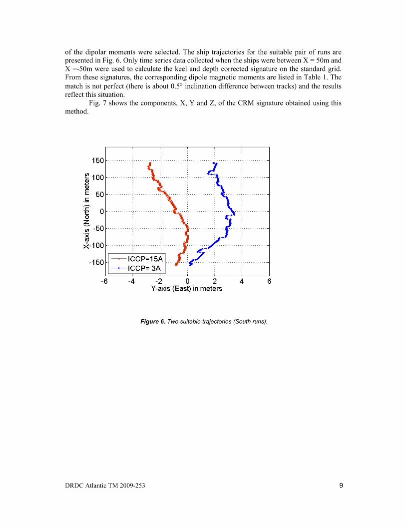
of the dipolar moments were selected. The ship trajectories for the suitable pair of runs are presented in Fig. 6. Only time series data collected when the ships were between X = 50m and X =-50m were used to calculate the keel and depth corrected signature on the standard grid. From these signatures, the corresponding dipole magnetic moments are listed in Table 1. The match is not perfect (there is about 0.5° inclination difference between tracks) and the results reflect this situation.
Fig. 7 shows the components, X, Y and Z, of the CRM signature obtained using this method.
Figure 6. Two suitable trajectories (South runs).

10 DRDC Atlantic TM 2009-253
Figure 7. The components of the measured CRM signature.

DRDC Atlantic TM 2009-253 11
4. Calculation
4.1 Principle of calculation The aim of the second part of the report is to predict the CRM signature, a quantity
that is not directly measurable, given the geometry of the ship and the electric field generated from the corrosion currents.
Consider the simple case of a ship in the seawater that is corroding without cathodic protection (Fig. 1). Its corrosion surface (protected with paint coating only) is limited by the sea surface. From the hull corrosion currents will be emitted and flow through the seawater to the propeller. Because these currents are distributed within the conducting water (and seafloor) volume they are called the “volume currents”. Since no net current can escape from the ship, a current loop must be formed with the current absorbed at the propeller flowing back through the ship, via the propeller shaft, to the hull. This is the so-called the “return current”. Summing up the contributions from the volume and the return currents, the total CRM field at a point in the seawater may be estimated using the Biot-Savart law. The result depends on knowing what current is emitted from different parts of the hull.
If the current flow J(r’) can be fully described within the conducting region (volume), Ω, then the law of Biot-Savart can be applied to calculate the magnetic field at any position, r:
( ) ( ) '4 3 dv
r'rr'rr'JrB
−
−×= ∫Ωπ
µ (1)
where μ is the permeability of the media. The conducting region Ω may contain both the electrolyte (seawater) and the metallic structure.
Obtaining an expression for J requires solving for the electric potential V everywhere in the computation volume. This is achieved using the finite element (FE) method of electromagnetic computation, which requires a volume mesh. Then the current density is calculated:
Vgradσ−=J (2) where σ is the conductivity of the media where the current density is calculated. Notice that the calculation of the UEP signature (J) precedes the calculation of the CRM signature (B).
The principles of CRM signature calculation outlined above can also be applied when the ship is protected by an ICCP system. A model of the CFAV Quest was built using the FLUX-3D code (Fig. 8) whose Electrolysis module allows the calculation of the UEP and CRM signatures. The geometry of the underwater hull including the ICCP anodes, shafts, and propellers was accurately reproduced in the software together with the internal metallic structure of the ship. In Fig. 8 the green surface elements represent the painted hull, the blue patches are the anodes, and the brown patches may represent some damage (not considered here). For the UEP signature the internal metal structure of the ship is not considered, but for the CRM calculation it has to be taken into account to model the magnetic field in the water produced by the return current.

12 DRDC Atlantic TM 2009-253
In general, the position of the anodes and cathodes, and the ICCP currents are known,
making the computation of the UEP and CRM signatures very easy for the ideal case of a perfectly insulated hull. For a real ship with paint damage more information is required about the current distribution on the hull because, in addition to the ICCP current, various surfaces may act as anodes or cathodes depending on their potential. An accurate determination of the current emitted from each part of the hull is not possible, but an overall current distribution on the hull may be determined by potential inversion [4, 5].
The computation of the CRM signature can be carried out for the ideal case of a perfectly insulated hull and the inversion is not necessary because the magnetic signatures subtraction eliminated the effect of damaged paint. The UEP signature calculation was performed for verification purposes only. There are numerous published articles reporting the validation of corrosion modeling using the UEP measurements [6].
4.2 Results and discussion
From the FE modeling, one can see that the prediction of the X-component of the UEP signal calculated for an ICCP current of 12A and presented in Fig. 9 is in good agreement with the one in Fig. 3. However, the calculated CRM signature shown in Fig. 10 - 12 has similar shape, but smaller values than the measurements (Fig. 7). The explanation of this discrepancy is the amount of errors affecting the two measurements: while a small
Figure 8. FE model of the CFAV Quest.

DRDC Atlantic TM 2009-253 13
misorientation of the ship from the N-S direction does not change significantly the UEP signature, its magnetic signature may change enough to mask the CRM effect. For example, it can be easily shown that the difference between the Y-components of the magnetic signature is more then 300nT when using the data for runs 5 and 21 in Table 1 and the magnetic dipole model.
As mentioned, there may be magnetic measurement errors due to the imperfect range calibration, but more important is the variation of the ship magnetization from one run to the other due to the change of the ship orientation in the Earth’s magnetic field. Also, the assumption that the ICCP system fully protects the hull proves a lack of understanding of the corrosion mechanism. In reality, the current distribution around the ship may be very different than the one generated by the ideal model. The real current distribution that would be obtained from a full UEP signature by inversion, for example, was not introduced into the model. This lack of information may also lead to wrong results.
Considering that we are looking for a weak signal of ±100nT buried in about ±3000 nT, the results can be regarded as satisfactory in the sense that the modeled values of the CRM signature are of the same order of magnitude with the measured one.
Figure 9. Calculated UEP signature from the FE model.

14 DRDC Atlantic TM 2009-253
Figure 10. Calculated X-CRM signature from FE model.
Figure 11. Calculated Y-CRM signature from FE model.

DRDC Atlantic TM 2009-253 15
Figure 12. Calculated Z-CRM signature from FE model.

16 DRDC Atlantic TM 2009-253
5. Conclusion
A method to measure the CRM signature is proposed in this paper based on the difference between two magnetic signatures recorded at different settings of the ICCP current. Although this method needs future refinements, it offered the first measured CRM signature to serve for validation of the computer simulations.
The signature obtained after the total magnetic signatures subtraction represents the CRM signature created by the current difference between the two ICCP settings. The ICCP current was introduced into the FE model of the vessel to demonstrate the ability of the computational models to predict the ship electromagnetic signatures.
The magnetic signatures were recorded simultaneously with the X-component of the UEP signature. The literature offers numerous examples of UEP measurements that validate the modeling, so that the UEP data can be used to verify the calculation in this case.
With realistic parameters (hull geometry, anode and cathode positions, water and metal conductivity) the prediction of the UEP signal was similar to the measured one, while the CRM signature was smaller than the measurement but of the same order of magnitude. The discrepancy is partly due to the measurement variations introduced by the ship misorientation from the North-South direction.
This report outlines the difficulties to perform the CRM signature measurements using a moving ship ranging that may be solved either by using a fixed ranging facility or by modeling. The final goal of this work is to show that the modeling offers sufficient accuracy in predicting the UEP and CRM signatures and hence deduce their impact on the electromagnetic signature of a vessel.

DRDC Atlantic TM 2009-253 17
6. References [1] P. Allan and A. Watt, Modeling the corrosion related EM signatures of ships, International Conference on Marine Electromagnetics, MARELEC 2004, London UK, 17-18 March 2004. [2] M. Atlar, E.J. Glover, C.D. Anderson and R.J. Mutton, Effect of new-generation coatings on high speed propeller performance, Warship Cathodic Protection Symposium, 2003. [3] R. Adey and J. Baynham, Predicting corrosion related electrical and magnetic fields using BEM, in the BEASY documentation. [4] M. Birsan, Prediction of the ship’s permanent magnetization. Applied on CFAV Quest, DRDC Atlantic TM 2008-186. [5] H. Claesson, J. Mattsson and P. Krylsteadt, Inverse electrostatic source localization and modeling in dispersive horizontally stratified media – a comparison of continuous and discrete models, International Conference on Marine Electromagnetics, MARELEC 2001, Stockholm, Sweden, 11-13 July 2001. [6] P.G. Rawlins, C.P. Ganderton, B. O’Connell, A.R. Twelvetrees and R.C. Simmonds, Measurements of corrosion currents in seawater in order to validate vessel corrosion modeling, Cathodic Protection Workshop, 2001.

18 DRDC Atlantic TM 2009-253
List of symbols/abbreviations/acronyms/initialisms
DND
Department of National Defence
CFAV Canadian Forces Auxiliary Vessel CP Cathodic Protection CRM Corrosion Related Magnetic ICCP Impressed Current Cathodic Protection SACP Sacrificial Anodes Cathodic Protection UEP Underwater Electric Potential

DRDC Atlantic TM 2009-253 19
Distribution list
DRDC Atlantic TM 2009-253
LIST PART 1: Internal Distribution by Centre: 1 Author 3 DRDC Atlantic Library --------------------------------------------- 4 TOTAL LIST PART 1
LIST PART 2: External Distribution by DRDKIM 1 DRDKIM 1 Library and Archives Canada, Attn: Military Archivist, Government Records Branch 2 DMSS 2
1 Director-General
Institute for Ocean Technology National Research Council of Canada PO Box 12093, Station A St. John’s, Newfoundland A1B 3T5
1 Commanding Officer
US Coast Guard Research and Development Center 1082 Shennecosett Road Groton, CT 06340-2602 USA
------------------------------------------------- 6 TOTAL LIST PART 2 10 TOTAL COPIES REQUIRED

20 DRDC Atlantic TM 2009-253
This page intentionally left blank.

DRDC Atlantic mod. May 02
DOCUMENT CONTROL DATA (Security classification of title, body of abstract and indexing annotation must be entered when the overall document is classified)
1. ORIGINATOR (the name and address of the organization preparing the document. Organizations for whom the document was prepared, e.g. Centre sponsoring a contractor's report, or tasking agency, are entered in section 8.) Defence R&D Canada - Atlantic, PO Box 1012, Dartmouth, NS, Canada B2Y 3Z7
2. SECURITY CLASSIFICATION (overall security classification of the document
including special warning terms if applicable). UNCLASSIFIED
3. TITLE (the complete document title as indicated on the title page. Its classification should be indicated by the appropriate abbreviation (S,C,R or U) in parentheses after the title). Measurement and model predicted corrosion related magnetic signature: Applied on CFAV Quest.
4. AUTHORS (Last name, first name, middle initial. If military, show rank, e.g. Doe, Maj. John E.) Marius Birsan
5. DATE OF PUBLICATION (month and year of publication of document)
October 2010
6a. NO. OF PAGES (total containing information Include Annexes, Appendices, etc).
30
6b. NO. OF REFS (total cited in document)
6
7. DESCRIPTIVE NOTES (the category of the document, e.g. technical report, technical note or memorandum. If appropriate, enter the type of report, e.g. interim, progress, summary, annual or final. Give the inclusive dates when a specific reporting period is covered).
Technical Memorandum
8. SPONSORING ACTIVITY (the name of the department project office or laboratory sponsoring the research and development. Include address). Defence R&D Canada - Atlantic PO Box 1012 Dartmouth, NS, Canada B2Y 3Z7
9a. PROJECT OR GRANT NO. (if appropriate, the applicable research
and development project or grant number under which the document was written. Please specify whether project or grant). Project 11cj
9b. CONTRACT NO. (if appropriate, the applicable number under which the document was written).
10a ORIGINATOR'S DOCUMENT NUMBER (the official document
number by which the document is identified by the originating activity. This number must be unique to this document.) DRDC Atlantic TM 2009-253
10b OTHER DOCUMENT NOs. (Any other numbers which may be assigned this document either by the originator or by the sponsor.)
11. DOCUMENT AVAILABILITY (any limitations on further dissemination of the document, other than those imposed by security classification)
( X ) Unlimited distribution ( ) Defence departments and defence contractors; further distribution only as approved ( ) Defence departments and Canadian defence contractors; further distribution only as approved ( ) Government departments and agencies; further distribution only as approved ( ) Defence departments; further distribution only as approved ( ) Other (please specify):
12. DOCUMENT ANNOUNCEMENT (any limitation to the bibliographic announcement of this document. This will normally correspond to the Document
Availability (11). However, where further distribution (beyond the audience specified in (11) is possible, a wider announcement audience may be selected).

DRDC Atlantic mod. May 02
13. ABSTRACT (a brief and factual summary of the document. It may also appear elsewhere in the body of the document itself. It is
highly desirable that the abstract of classified documents be unclassified. Each paragraph of the abstract shall begin with an indication of the security classification of the information in the paragraph (unless the document itself is unclassified) represented as (S), (C), (R), or (U). It is not necessary to include here abstracts in both official languages unless the text is bilingual).
In simple terms the corrosion related magnetic (CRM) field arises due to the flow of corrosion currents through the sea water. This current density has many sources with one of the most prominent being the currents that arise due to the corrosion of the metal work of the ship. Various corrosion countermeasures, for example an impressed current cathodic protection (ICCP) system, also directly affect the current density and hence an accurate model of the electromagnetic signatures can provide crucial information about the level of corrosion on the ship.
Computer models based on finite or boundary element methods have been used
for some years to predict the electric and magnetic signatures of vessels created by their cathodic protection (CP) systems. The literature presents good agreements between the electric field values obtained from the computer models and from the measurements on physical scale models or even on the real ships. However, at this time corrosion-related magnetic (CRM) signatures have only been predicted and no reference is made to the accuracy of such calculations. This report describes the theoretical background of the CRM signature calculation, and compares the model prediction with the measured CRM signature of the Canadian research vessel CFAV Quest.
14. KEYWORDS, DESCRIPTORS or IDENTIFIERS (technically meaningful terms or short phrases that characterize a
document and could be helpful in cataloguing the document. They should be selected so that no security classification is required. Identifiers, such as equipment model designation, trade name, military project code name, geographic location may also be included. If possible keywords should be selected from a published thesaurus. e.g. Thesaurus of Engineering and Scientific Terms (TEST) and that thesaurus-identified. If it not possible to select indexing terms which are Unclassified, the classification of each should be indicated as with the title). corrosion related magnetic, magnetic silencing, degaussing, ranging operation.

This page intentionally left blank.