Embed Size (px)
Citation preview
Measurement and Analysis of Weather Phenomena with K-Band Rain Radar
Jun-Hyeong Park Dept. of Electrical Engineering
KAIST DaeJeon, Republic of Korea
Ki-Bok Kong Development team Kukdong Telecom
Nonsan, Republic of Korea [email protected]
Seong-Ook Park Dept. of Electrical Engineering
KAIST DaeJeon, Republic of Korea
Abstract—To overcome blind spots of an ordinary weather radar which scans horizontally at a high altitude, a weather radar which operates vertically, so called an atmospheric profiler, is needed. In this paper, a K-band radar for observing rainfall vertically is introduced, and measurement results of rainfall are shown and discussed. For better performance of the atmospheric profiler, the radar which has high resolution even with low transmitted power is designed. With this radar, a melting layer is detected and some results that show characteristics of the meting layer are measured well.
Keywords—K-band; FMCW; rain radar; low transmitted power; high resolution; rainfall; melting layer
I. INTRODUCTION A weather radar usually measures meteorological
conditions of over a wide area at a high altitude. Because it observes weather phenomena in the area, it is mainly used for weather forecasting. However, blind spots exist because an ordinary weather radar scans horizontally, which results in difficulties in obtaining information on rainfall at higher and lower altitudes than the specific altitude. Therefore, a weather radar that covers the blind spots is required.
A weather radar that scans vertically could solve the problem. This kind of weather radar, so called an atmospheric profiler, points towards the sky and observes meteorological conditions according to the height [1]. Also, because the atmospheric profiler usually operates continuously at a fixed position, it could catch the sudden change of weather in the specific area.
In this paper, K-band rain radar which has low transmitted power and high resolutions of the range and the velocity is introduced. The frequency modulated continuous wave (FMCW) technique is used to achieve high sensitivity and reduce the cost of the system. In addition, meteorological results are discussed. Reflectivity, a fall speed of raindrops and Doppler spectrum measured when it rained are described, and characteristics of the melting layer are analyzed as well.
II. DEVELOPMENT OF K-BAND RAIN RADAR SYSTEM
A. Antenna To suppress side-lobe levels and increase an antenna gain,
offset dual reflector antennas are used [2]. Also, separation
wall exists between the transmitter (Tx) and receiver (Rx) antennas to improve isolation between them. With these methods, leakage power between Tx and Rx could be reduced. Fig. 1 shows manufactured antennas and the separation wall.
B. Design of Tranceiver Fig. 2 shows a block diagram of the K-band rain radar.
Reference signals for all PLLs in the system and clock signals for every digital chip in baseband are generated by four frequency synthesizers. In the Tx baseband module, a field programmable gate array (FPGA) controls a direct digital synthesizer (DDS) to generate an FMCW signal which decreases with time (down-chirp) and has a center frequency of 670 MHz. The sweep bandwidth is 50 MHz which gives the high range resolution of 3 m. Considering the cost, 2.4 GHz signal used as a reference clock input of the DDS is split and used for a local oscillator (LO). the FMCW signal is transmitted toward raindrops with the power of only 100 mW. Beat frequency which has data of the range and the radial velocity of raindrops is carried by 60 MHz and applied to the input of the Rx baseband module. In the Rx baseband module, quadrature demodulation is performed by a digital down converter (DDC). Thus, detectable range can be doubled than usual. Two Dimensional-Fast Fourier Transform (2D-FFT) is performed by two FPGAs. Because the 2D FFT is performed with 1024 beat signals, the radar can have high resolution of the radial velocity. Finally, data of raindrops are transferred to a PC with local LAN via the an UDP protocol. TABLE I. shows main specification of the system.
Fig. 1. Manufactured antenna and separation wall.
2016 URSI Asia-Pacific Radio Science Conference August 21-25, 2016 / Seoul, Korea
1
Multi-Band Multi-Mode SDR Radar Platform for Traffic and Security Applications
Young-Kil Kwag School of Electronics and Information Engineering
Korea Aerospace University Goyang-City, Korea [email protected]
In-Sang Woo Radar Research Institute
Korea Aerospace University Goyang-City, Korea
Abstract— This paper presents the new development results of the multi-band, multi-mode software-defined radar (SDR) platform. The SDR platform consists of multi-band RF modules of S, X, K-bands, and a multi-mode digital modules with a waveform generator for CW, Pulse, FMCW, and LFM Chirp as well as reconfigurable SDR-GUI software module for user interface. This platform can be used for various applications such as traffic monitoring and surveillance, and security.
Keywords—Software Defined Radar (SDR); radar system design; multi-band; multi-mode radar
I. INTRODUCTION
Software defined radar (SDR) has been drawing many advantages such as a multipurpose system, the ability to re-using the hardware, ease of implementation of signal processing algorithms, faster development and cost reduction. A SDR radar system is becoming feasible to be implemented due to the recent matured growth of the core radar technology. This makes the radar development easier to the users’ applications for multi-purpose, high performance, small size, and low cost [1]. In SDR system, most of the hardware processing, like waveform generation, up and down conversion of IF to baseband, and radar signal processors are performed by software based programming. The low-cost Universal Software Radio Peripheral (USRP) is one of the most well-known SDR platforms, however, the radar is limited to narrow bandwidth and the digital processor is low speed, and the USB interface between the host PC and processor limit the system performance [2].
This paper presents a new development of the multi-band, multi-mode SDR radar platform. Section II introduces the design specifications of SDR radar platform, and Section III presents the results of the implemented SDR hardware and software platform with the applications. Finally, Section IV summarizes the conclusion.
II. DESIGN OF SOFTWARE DEFINED RADAR
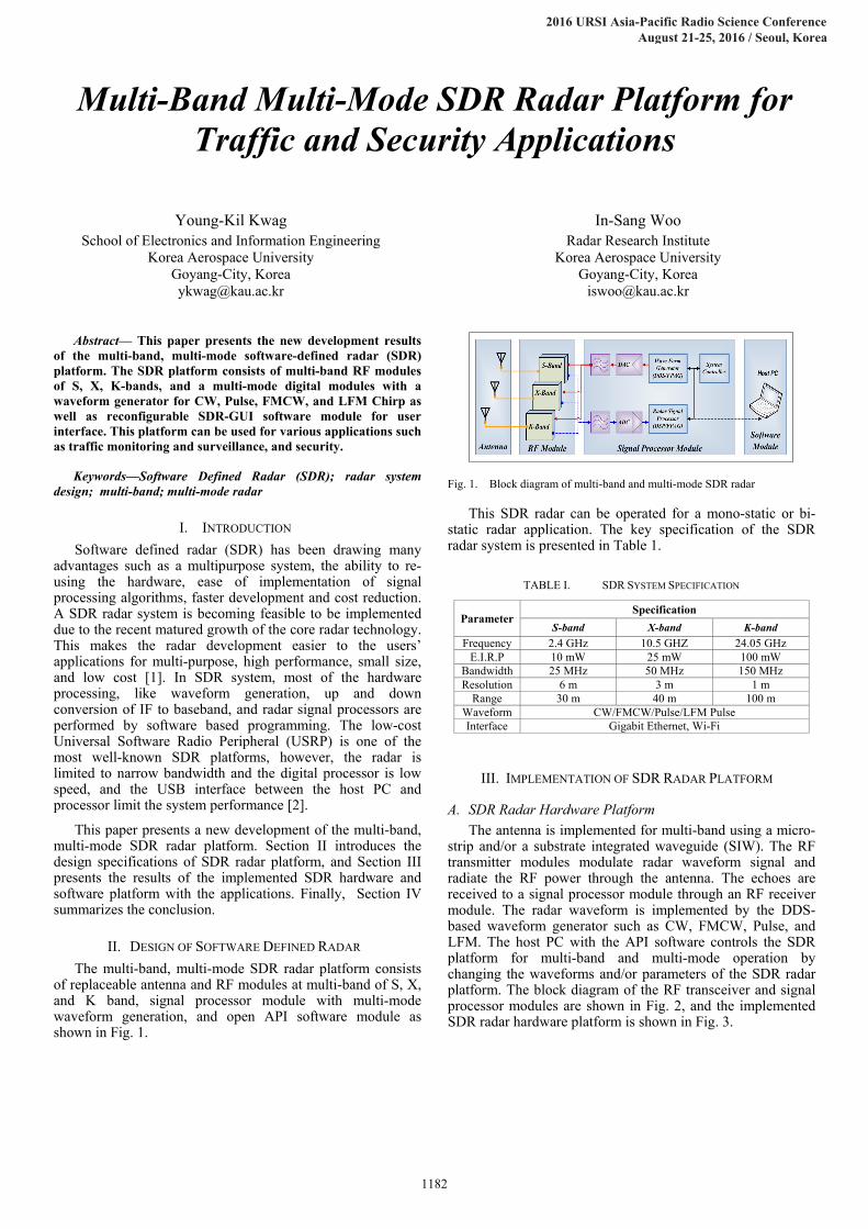
The multi-band, multi-mode SDR radar platform consists of replaceable antenna and RF modules at multi-band of S, X, and K band, signal processor module with multi-mode waveform generation, and open API software module as shown in Fig. 1.
Fig. 1. Block diagram of multi-band and multi-mode SDR radar
This SDR radar can be operated for a mono-static or bi-static radar application. The key specification of the SDR radar system is presented in Table 1.
TABLE I. SDR SYSTEM SPECIFICATION
Parameter Specification
S-band X-band K-band
Frequency 2.4 GHz 10.5 GHZ 24.05 GHz E.I.R.P 10 mW 25 mW 100 mW
Bandwidth 25 MHz 50 MHz 150 MHz Resolution 6 m 3 m 1 m
Range 30 m 40 m 100 m Waveform CW/FMCW/Pulse/LFM Pulse Interface Gigabit Ethernet, Wi-Fi
III. IMPLEMENTATION OF SDR RADAR PLATFORM
A. SDR Radar Hardware Platform The antenna is implemented for multi-band using a micro-
strip and/or a substrate integrated waveguide (SIW). The RF transmitter modules modulate radar waveform signal and radiate the RF power through the antenna. The echoes are received to a signal processor module through an RF receiver module. The radar waveform is implemented by the DDS-based waveform generator such as CW, FMCW, Pulse, and LFM. The host PC with the API software controls the SDR platform for multi-band and multi-mode operation by changing the waveforms and/or parameters of the SDR radar platform. The block diagram of the RF transceiver and signal processor modules are shown in Fig. 2, and the implemented SDR radar hardware platform is shown in Fig. 3.
1182
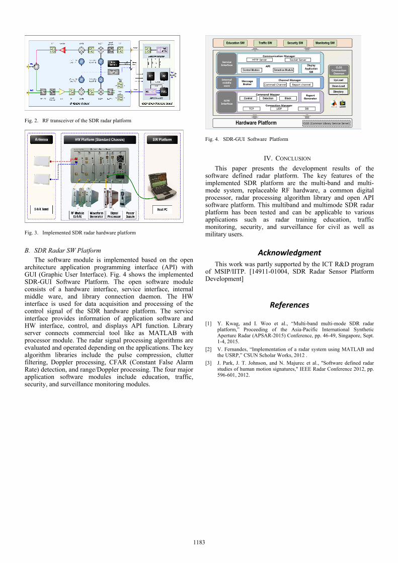
Fig. 2. RF transceiver of the SDR radar platform
Fig. 3. Implemented SDR radar hardware platform
B. SDR Radar SW Platform The software module is implemented based on the open
architecture application programming interface (API) with GUI (Graphic User Interface). Fig. 4 shows the implemented SDR-GUI Software Platform. The open software module consists of a hardware interface, service interface, internal middle ware, and library connection daemon. The HW interface is used for data acquisition and processing of the control signal of the SDR hardware platform. The service interface provides information of application software and HW interface, control, and displays API function. Library server connects commercial tool like as MATLAB with processor module. The radar signal processing algorithms are evaluated and operated depending on the applications. The key algorithm libraries include the pulse compression, clutter filtering, Doppler processing, CFAR (Constant False Alarm Rate) detection, and range/Doppler processing. The four major application software modules include education, traffic, security, and surveillance monitoring modules.
Fig. 4. SDR-GUI Software Platform
IV. CONCLUSION
This paper presents the development results of the software defined radar platform. The key features of the implemented SDR platform are the multi-band and multi-mode system, replaceable RF hardware, a common digital processor, radar processing algorithm library and open API software platform. This multiband and multimode SDR radar platform has been tested and can be applicable to various applications such as radar training education, traffic monitoring, security, and surveillance for civil as well as military users.
Acknowledgment This work was partly supported by the ICT R&D program
of MSIP/IITP. [14911-01004, SDR Radar Sensor Platform Development]
References
[1] Y. Kwag, and I. Woo et al., “Multi-band multi-mode SDR radar platform,” Proceeding of the Asia-Pacific International Synthetic Aperture Radar (APSAR-2015) Conference, pp. 46-49, Singapore, Sept. 1-4, 2015.
[2] V. Fernandes, “Implementation of a radar system using MATLAB and the USRP,” CSUN Scholar Works, 2012 .
[3] J. Park, J. T. Johnson, and N. Majurec et al., "Software defined radar studies of human motion signatures," IEEE Radar Conference 2012, pp. 596-601, 2012.
1183