Embed Size (px)
Citation preview

2558 J. Opt. Soc. Am. B/Vol. 13, No. 11 /November 1996 A. Krause and G. Notni
Measurement accuracy of interferometers withself-pumped phase-conjugate mirrors
Axel Krause and Gunther Notni
Fraunhofer-Institute for Applied Optics and Precision Engineering, Schillerstrasse 1, 07745 Jena, Germany
Received January 17, 1996; revised manuscript received June 19, 1996
Quantitative measurements of the accuracy of interferometers with self-pumped phase-conjugate mirrors(SPPCM’s) involving the application of different kinds of SPPCM’s as the reference mirror, the cat-conjugatorSPPCM, the backscattering SPPCM, and an external resonator SPPCM are shown, for the first time to ourknowledge. We prove that the only way to achieve the same measurement accuracy as with classical inter-ferometric systems is by use of the cat-conjugator SPPCM. Because of the external feedback in both of theother types of SPPCM, a phase error is introduced, resulting in a phase error in the interferogram. In addi-tion, experimental data describing the time behavior of SPPCM’s, which is important for some interferometricapplications, are given. An interferometer with a SPPCM for testing aspherical surfaces is presented.© 1996 Optical Society of America.
1. INTRODUCTION
Over the past 15 years optical phase conjugation has de-veloped into a multipurpose procedure in modern optics.Applications of optical phase conjugation are proposedand are also of practical use in adaptive optics, real-timemeasurement techniques, and optical information pro-cessing. Good surveys of this field are given in Refs. 1–3.Accordingly, phase conjugation also offers very valuablenew advantages to interferometry,4 including correctionof aberrations,5 doubling of the sensitivity of phasemeasurements,6 and wave-front storage in real time.7
These developments were stimulated, above all, by theapplication of photorefractive crystals (e.g., BaTiO3,Bi12TiO20 , Bi12GeO20, Bi12SiO20) as phase-conjugate mir-rors (PCM’s), both in external and self-pumped configura-tions. These materials have been recognized for a longtime as sensitive media with low-energy requirements.In principle, different types of self-pumped phase-conjugate mirrors (SPPCM’s) based on photorefractivecrystals can be used in interferometric arrangements, forexample, the total-internal-reflection SPPCM8 (TIR-PCM,usually called the cat-conjugator), the seeded backscatter-ing SPPCM9 (BS-PCM; see Fig. 1), and phase-conjugatingexternal resonators (ER-PCM; see Fig. 2).10
In an interferometer the PCM must fulfill certain con-ditions. First, of course, good phase conjugation is re-quired. Second, stability of the reflected power is needed.This is of special importance in phase-shifting interferom-eters, in which the accuracy depends directly on this sta-bility. Third, some applications demand that the PCMdemonstrates a good time behavior. In wave-front sens-ing devices the response time determines how fast thewave front is allowed to change to yield a correct result.In Section 2 the attractive properties of two-beam in-
terferometers with SPPCM’s are discussed. Different in-terferometric arrangements have been proposed for thedetermination of the shape of optical elements, especiallyspherical, cylindrical, and aspherical ones,11–13 and of
0740-3224/96/1102558-11$10.00
wave fronts.11,12,14 We have built interferometers withSPPCM’s that use phase-shifting techniques and in thispaper give quantitative results for them. To our knowl-edge, we are the first to build an interferometer for thetesting of aspherical surfaces by using a computer-generated hologram (CGH) as a null compensator, whichis located at the entrance of the interferometer; the wavefront is in the reference arm reflected by a SPPCM. InSections 3 and 4 we present measurements that are nec-essary to determine the achievable accuracy of interfer-ometers with SPPCM’s for the above-mentioned SPPCMvariants. To assess the response of a SPPCM to intro-duced phase steps we applied the spatial ellipse-fittingtechnique for estimating the size of the phase shift in theobtained interferograms. To determine the interfero-metrical accuracy we modified a commercial Twyman–Green interferometer in such a way that one can choosebetween a SPPCM and a classical mirror as a referencemirror. In Section 5 we present experimental data de-scribing the time behavior of the investigated SPPCMtypes.
2. TWO-BEAM INTERFEROMETERS WITHPHASE-CONJUGATE MIRRORS FORTESTING ASPHERICAL SURFACESOptical measurement technique ought to determine theshape of surfaces of optical elements with an accuracy of afraction of the wavelength of light (typical values arel/100).11 The measurements should be contactless andshould be able to test very different shapes of surfaces, forexample, of plane, spherical, cylindrical, conicoidal, andaspherical form. In practice, interferometric methodsare established in this field. Well-known systems areTwyman–Green and Fizeau interferometers. Shape-testing interferometers with PCM’s increase the capabil-ity of these setups in the field of optical measurements.Consider a Twyman–Green interferometer with a PCMfor examining concave spherical surfaces (mirrors),13 asillustrated in Fig. 3.
© 1996 Optical Society of America

A. Krause and G. Notni Vol. 13, No. 11 /November 1996 /J. Opt. Soc. Am. B 2559
For the purpose of a better quantitative analysis of theobtained interferogram, we introduced a phase-shiftingunit into the reference path. If the surface under testhas an ideal spherical shape and is perfectly aligned, theinterferogram will show uniform brightness (no interfer-ence fringes). Each deviation of the object surface from asphere causes a deviation of the test wave from a spheri-cal wave that results in interference fringes. Note thatthe reference wave is always an aberration-free idealspherical reference wave because all aberrations intro-duced by the focusing lens and the beam splitter are com-pensated in the returned path (self-focusing property ofthe PCM) under the assumption that the PCM does notintroduce any undesirable phase error (see Sections 3 and4). This results in the following general advantages ofshape-testing interferometers with PCM’s compared withconventional systems. In the reference arm neither amaster object that is well adapted to the surface undertest nor a combination of a high-corrected collimation ob-jective and a plane mirror are needed. These interferom-eters do not require a compensation plate in the test armor a high-symmetrical beam splitter. They are simple toadjust and show a high flexibility because of the self-aligning. The aperture is limited only by the beam split-ter and not by additional collimator systems. The prin-ciple of measurement described here can be transformedto Fizeau interferometers for testing of the shape of thesurface of transparent objects.15 Here the PCM is lo-cated behind the object under test and reflects the trans-mitted wave.Different arrangements for the testing of aspherical
surfaces by interferometric methods have been
Fig. 1. Scheme of the seeded backscattering SPPCM(BS-PCM).9
Fig. 2. Scheme of the phase-conjugating resonator (ER-PCM).10
proposed.16–18 Most of them, however, are difficult to ad-just. Often only rotationally symmetric objects can betested.17
To overcome these restrictions we propose to use aPCM as a reference mirror in combination with a nullcompensator at the entrance of the interferometer,19 (seeFig. 3). Null compensators adapt the test wave front tothe desired shape of the surface under test; therefore, atthe exit of the interferometer, we observe uniform bright-ness, presuming that the object under test has no errors.Depending on the shape of the object, different null com-pensators have to be selected. For example, to measurecylindrical surfaces a well-adapted wave-front generatorconsists of a system that focuses a plane wave onto a slit;special lens systems are used for testing conicoidalsurfaces;20 CGH’s create wave fronts for the measure-ment of aspherical objects.19 Note that the number oflines per millimeter of the CGH determines the maximumpermissible gradient of the test wave front.The reference wave front of these interferometers is
generated by phase conjugation, with the expectation thatthe PCM acts as an ideal reference object independent ofthe shape of the incidence wave. This leads to a veryhigh flexibility of the interferometric setup because onlythe null compensator has to be adapted to the correspond-ing measurement. Moreover, the effort of alignment andthe risk of misalignment are smaller because only two op-tical components (null compensator and object under test)have to be adjusted to each other, so a better accuracy canbe expected. Misalignments in the reference arm are notpossible. In our case the alignment of a null compensa-tor that consists of a spatial-frequency filter and a CGH(see Fig. 4) is especially easy because the distance is theonly magnitude that varies. Furthermore, the computa-
Fig. 3. Twyman–Green interferometer with PCM: with micro-scope objective and pinhole for testing spherical surfaces; withnull compensator for testing aspherical surfaces.
Fig. 4. Null compensator, consisting of only a spatial-frequencyfilter and a CGH.

2560 J. Opt. Soc. Am. B/Vol. 13, No. 11 /November 1996 A. Krause and G. Notni
tion of a CGH as a null compensator is simplified com-pared with conventional arrangements because only free-space propagation has to be taken into considerationbetween the CGH and the object.For this kind of null compensator we suggest the fol-
lowing applied method for the evaluation of the CGH.The wave front of the wave generated by the pinhole isevaluated in the plane of the CGH. This includes the op-tical effect of the support of the CGH. One evaluates asecond wave front, starting at the aspherical surface.Here the wave front has the same form as the desiredshape of the aspherical surface. It propagates throughfree space to the plane of the CGH. The resulting wavefront in this plane is evaluated. Both wave fronts forman interferogram that is approximated by a Householdertransformation. The result is digitized to the form usedfor steering the electron-beam writing system. The ad-vantage of this method is that the CGH can be directlyevaluated from the data of the aspherical surface. Thisis much easier than an approximation procedure, which isnecessary when one is using refractive optics as a nullcompensator. However, some restrictions are imposed infollowing this procedure. The size of the CGH is deter-mined by the area of the wave front originating from theaspherical surface and propagating to the plane of theCGH. It must be small enough that the CGH can bewritten in a usual time and on a usual working area of
Fig. 5. Measured phase distribution of the interferogram fortesting an aspherical surface.
Fig. 6. Measured deviation of a cylindrical surface from an idealcylindrical surface.
the electron-beam writing system. Moreover, the linedensity must be within the limits of that system.To demonstrate this procedure we chose a parabolic
mirror, 100 mm in diameter, with an f-number of 1/5.This mirror should have a surface quality of l/5. Themeasured phase distribution of the interferogram isshown in Fig. 5. After eliminating defocus and tilt, wereceive a peak-to-valley (p–v) value of l/2 related to thesurface. This value is the sum of the surface error of theelement under test and the interferometer error, includ-ing misalignment of the null compensator. A furthersplitting up of this sum into terms corresponding to thenumerous elements of the interferometer demands moresophisticated methods, such as absolute interferometricmethods.The achieved result shows that the suggested solution
represents a new way of testing aspherical surfaces.Testing of nonrotationally symmetric objects can be donein this way without any problem because nonrotationallysymmetric CGH’s can be written without difficulty.Another essential problem is the testing of cylindrical
surfaces. This is especially important for technical sur-faces, for instance, liners and optical elements forscanners.21,22 Here we have the same problem as in theinterferometer for aspherical surfaces: the generation ofa wave front that is adapted to the cylindrical surface.One solution, of course, could be the same as that foraspherical surfaces: use of a CGH. Another solution isto build a one-dimensional spatial filter analogous to thetesting of spherical surfaces. However, it is hard to findstock optics working according to the condition of spatialfiltering. We did not achieve a homogeneous illumina-tion for a slit with the width of a few micrometers and alength of a few millimeters. So for demonstration pur-poses we used the combination of a photo-objective lensand a cylindrical lens. For testing of cylindrical surfacesthe collimation system in the reference arm must includea cylindrical element.As an example, we show in Fig. 6 the resulting phase
distribution of measuring the surface of a cylindrical lens.This interferometer has the advantage that the cylindri-cal axis is not influenced by the reference arm. Notethat, by using cylindrical focusing in the SPPCM, one cangreatly reduce the buildup times.23
3. PHASE-SHIFTING ALGORITHMS ININTERFEROMETERS WITH PHASECONJUGATE MIRRORSTo our knowledge, an exact quantitative analysis of theinterferograms obtained in interferometers withSPPCM’s was not given until this writing, so no state-ment about the achievable accuracy was available.Different techniques for a quantitative fringe pattern
analysis are well known, including Fourier transfor-mation,24 fringe-tracking, phase-shifting, and heterodynetechniques (see e.g., Ref. 25). Among these techniques,phase shifting is the technique with the highest achievedlevel of accuracy to date. By means of the phase-shiftingtechnique the phase of the interferogram can be evalu-ated for every pixel of the CCD camera independent of theneighboring pixels and, to a great extent, independent of

A. Krause and G. Notni Vol. 13, No. 11 /November 1996 /J. Opt. Soc. Am. B 2561
the contrast. Unlike Fourier transformation and fringetracking, phase shifting is independent of the phase dis-tribution in the interferogram. But it has the disadvan-tage that at least three phase-shifted interferograms areneeded for the evaluation of the phase distribution.Note that there is no carrier frequency in interfero-
grams obtained from phase-conjugate Fizeau interferom-eters for wave-front sensing. This is because the wavefront under measurement is made to interfere with itsown wave-front reverse replica (a so-called conjugateshear interferogram is obtained). So Fourier transforma-tion is not well adapted to these interferograms. Forthese reasons we focused our interest on the applicabilityof phase-shifting techniques.
A. Theoretical BackgroundIf phase-shifting techniques are to be used in interferom-eters with PCM’s, one has to consider whether such tech-niques are applicable. For instance, if one is applyingSPPCM’s on the basis of photorefractive crystals, one hasto guarantee the entrance position and the polarizationstate at the crystal. Because of the process of phase con-jugation (aberration cancellation) it is conceivable that allthe aberrations of a wave (including the uniform phaseshift caused by a phase shifter) are canceled out on the
Fig. 7. Experimental arrangement for the phase-shifter calibra-tion (1–4 beam splitters, 5–8 mirrors).
Fig. 8. Phase difference in the Michelson interferogram versusphase difference in the Mach–Zehnder interferogram with theuse of a liquid-crystal device as phase shifter (straight, best lin-ear fit).
wave’s way back through the aberrating elements, includ-ing the phase-shifting device. Because of this fact, itseems to be impossible to use conventional phase-shiftingelements placed in the reference beam for an effectivephase shift in interferometry.Some authors are concerned with this topic.6,26 The
basic results are as follows.When one is using an externally pumped phase-
conjugate mirror (EPPCM), laterally uniform aberrations(so-called longitudinal aberrations) as well as laterallyvarying (so-called transversal aberrations) are canceledout on the wave’s way back through the aberrator. Thismeans that, after insertion of an aberrator into the refer-ence beam of this kind of interferometer, exactly the sameinterferogram is formed as there was without the aberra-tor.In interferometers in which SPPCM’s are used as the
reference mirror, only the transversal part of the aberra-tions is canceled out; the laterally constant part of the ab-erration is, however, not influenced and should be de-tected in the interferogram as a uniform phase shift.A simple phenomenological explanation of this effect is
that an EPPCM has some kind of information about theabsolute phase of the signal wave, whereas a SPPCM hasnot. The information source for the EPPCM are thepump waves, which are not affected by the phase shifterand serve as an absolute phase reference. In contrast, ina SPPCM all the waves involved in the phase-conjugationprocess are derived directly from the signal wave. So aphase shift a introduced to the signal wave impinging onthe SPPCM should be transferred to the reflected phase-conjugate wave. On the way back through the phaseshifter the wave undergoes another phase shift of thesame amount, so that a total phase shift of 2a should ap-pear in the interferogram.Summarizing, we can state that any uniform phase
shift introduced into the signal wave is not reversed butpreserved because of the reflection on a SPPCM. In con-clusion, all kinds of phase-shifting units, which introduce
Fig. 9. Experimental arrangement to determine the accuracy ofa phase-conjugate interferometer (K1, K2, swing-out mirrors;l/2, half-wave plate; l/4, quarter-wave plate; 1–3, special opticalsystems).
2562 J. Opt. Soc. Am. B/Vol. 13, No. 11 /November 1996 A. Krause and G. Notni
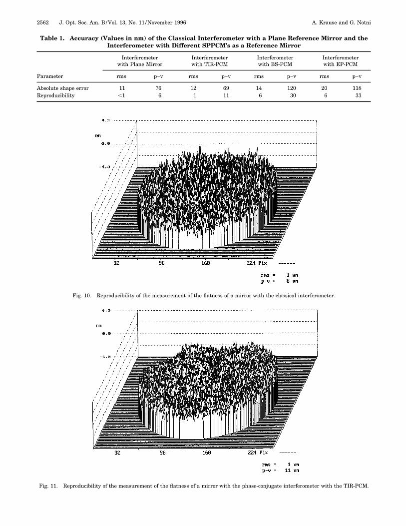
Fig. 10. Reproducibility of the measurement of the flatness of a mirror with the classical interferometer.
Fig. 11. Reproducibility of the measurement of the flatness of a mirror with the phase-conjugate interferometer with the TIR-PCM.
Table 1. Accuracy (Values in nm) of the Classical Interferometer with a Plane Reference Mirror and theInterferometer with Different SPPCM’s as a Reference Mirror
Interferometerwith Plane Mirror
Interferometerwith TIR-PCM
Interferometerwith BS-PCM
Interferometerwith EP-PCM
Parameter rms p–v rms p–v rms p–v rms p–v
Absolute shape error 11 76 12 69 14 120 20 118Reproducibility ,1 6 1 11 6 30 6 33

A. Krause and G. Notni Vol. 13, No. 11 /November 1996 /J. Opt. Soc. Am. B 2563
Fig. 12. Reproducibility of the measurement of the flatness of a mirror with the phase-conjugate interferometer with the BS-PCM.
only a longitudinal phase shift (e.g., tunable laser diodes,wedged-plate compensators, and liquid-crystal devices)can be applied in an interferometer with SPPCM’s.
B. Calibration of Phase-Shifting Units in Interferometerswith Self-Pumped Phase-Conjugate MirrorsTo test this explanation we performed some phase-shiftercalibration experiments (Fig. 7). In particular, we mea-sured the phase shifts in a Michelson interferometer withSPPCM’s (mirror 7 and the SPPCM) with respect to theintroduced phase shift. To measure the phase shift aMach–Zehnder interferometer (beam splitters 1–4) wasincluded. Both interferograms were simultaneously de-tected at different areas of the CCD-camera chip, and theamount of phase shift in each of the interferograms wascalculated independently by the spatial ellipse-fittingtechnique.28 Because of the double pass of the phase-conjugate wave through the phase-shifting element aphase shift aSPPCM 5 2a will appear in the Michelson in-terferogram, provided that the phase is not influenced bythe SPPCM. Hence the ratio Pshift 5 aSPPCM /a shouldalways be 2.Figure 8 shows the phase difference in the Michelson
interferogram versus the phase difference in the Mach–Zehnder interferogram, with the use of a liquid-crystaldevice as phase shifter. The voltage applied to the phaseshifter was increased by a constant amount, step by step.The slope of the straight line in Fig. 8 corresponds to theratio Pshift . We find the experimental result Pshift5 1.98 6 0.02. Simultaneously, the values for thephase difference in the Mach–Zehnder interferometeralso give the calibration curve for the phase shifter.In further experiments with other kinds of phase
shifters, including a wedge-plate phase shifter, we did notobserve a noticeable deviation of Pshift from the value 2.This result permits application of well-known phase-
shifting devices in the reference arm in an interferometerwith SPPCM’s, with the restriction that the phase shifterintroduces only a longitudinal phase shift and, further-more, no changes of the polarization state.
4. ACCURACY OF INTERFEROMETERSWITH SELF-PUMPED PHASE-CONJUGATEMIRRORSIn our opinion the accuracy of an interferometer with aSPPCM is influenced mainly by effects caused by theSPPCM itself. These effects are, for example, the phaseresponse and the nonstationary reflectivity.To compare the accuracy of a phase-conjugate interfer-
ometer with that of a well-developed phase-shift interfer-ometer, we extended a commercially available digital in-terferometer (Carl–Zeiss–Jena GmbH, Model HPI) by aphase-conjugate reference path. The arrangement isschematically shown in Fig. 9. In the HPI interferometer
Fig. 13. Stability of the reflectivity of different SPPCM types.

2564 J. Opt. Soc. Am. B/Vol. 13, No. 11 /November 1996 A. Krause and G. Notni
the phase steps are obtained by a polarization phaseshifter by means of the rotating half-wave plate in theoutput path. In the reference arm, swing-out mirror K2can be turned into the beam path. Then the referencewave front is reflected there and passes a quarter-waveplate, a half-wave plate, and a Faraday rotator to obtainthe necessary extraordinary-polarization state at thecrystal. It is focused by the lens into the SPPCM. Thecreated self-pumped phase-conjugate (SPPC) wave trav-els back, and all the aberrations introduced by the opticalelements are canceled out. Here we used low-quality op-tical elements from stock. The polarizing beam splittercombines both waves (SPPC wave and test wave), and aninterference structure can be observed. To supply thenecessary power at the location of the SPPCM a 75-mWHe–Ne laser was included in the system. The lasersource is selected according to the position of the swing-out mirror K1.The measurement regime was as follows. As a test ob-
ject we used a plane mirror of diameter 100 mm. Firstwe measured the shape of the mirror with the classicalTwyman–Green interferometer (swing-out mirror K2 wasnot in the reference arm). For this arrangement we de-termined the shape and the reproducibility of the mea-surement. For the determination of the reproducibilitywe measured the surface of the mirror two times, one af-ter the other, and evaluated the difference. We call theobtained difference reproducibility. One measurementtook 2.4 s; the interval between the two measurementswas 1 s. As characteristic values the root mean square(rms) value and the p–v value are given. After that, theswing-out mirror was swung into the reference path, andwe carried out the same measurements again, using theSPPC wave as the reference wave. The measurement re-gime was performed for each type of SPPCM.Table 1 shows the measured mean values of the rms
and the p–v values for all the measurement regimes.Note that a five-step phase-shifting technique with no fil-ter operation25 was used to determine the phase distribu-tion.Figures 10–12 show some measurements of the repro-
ducibility. Note that the values given in Table 1 for thereproducibility of the BS-PCM and the ER-PCM are meanvalues. The absolute phase of the phase-conjugate waveshows statistical fluctuations, in the time range of a fewseconds, which lead to a phase error in the measurement.Figure 12 is an example of a measurement with high rmsand p–v values that clearly shows the resulting measure-ment error. The high p–v values are evidence that thereare some runaway pixels in the interferogram.From Table 1 it is obvious that, with an interferometer
with SPPCM’s the shape error of an optical element canbe measured with the same accuracy (l/100) as with thehelp of a classic interferometer, but only by use of a TIR-PCM as a reference mirror. The reproducibility of themeasurements of the TIR-PCM phase-conjugate interfer-ometer is two times lower than that of a classical inter-ferometer (compare the p–v values in columns 1 and 2),which is caused by time effects (i.e., stability of the reflec-tivity) of the TIR-PCM used. In our arrangement we ob-tained a reflectivity of 50% at 633 nm, with a maximumstatistical change of the amplitude of the SPPC wave of
2% during the measurement time (see Fig. 13). Somenumericalsimulations show that this results in a mea-surement error of the p–v value of approximately 8 nmand of the rms value of approximately 1 nm, which is ofthe same order as the measured value. As a result, notethat for very-high-accuracy measurements, in which arms value of the reproducibility of better than 1 nm is re-quired, the reflectivity has to be stabilized to better than1%.In contrast, the two types of SPPCM with an external
feedback cannot be used in very-high-accuracy interfero-metric arrangements (see Table 1, columns 3 and 4). Itis possible to cancel out the aberrations introduced bylow-quality optics, but, unfortunately, a statistical abso-lute phase error is introduced in the SPPC wave. In ouropinion this is due to the external feedback. The exter-nal feedback from the foil or the mirror provides wavesthat are taking part in wave mixing processes with thephase-conjugate wave inside the crystal. In this wayfluctuations of the phase of the feedback waves influencethe phase of the phase-conjugate wave. Such phase fluc-tuations can be caused, for instance, by length changes ofthe feedback path. Consequently, a phase-shift error isintroduced, resulting in a periodic error of the phase mea-surements (see Fig. 12). This corresponds to the well-known interferometric analysis, whereby it has beenfound that a phase-shift error results in a periodic mea-surement error.25
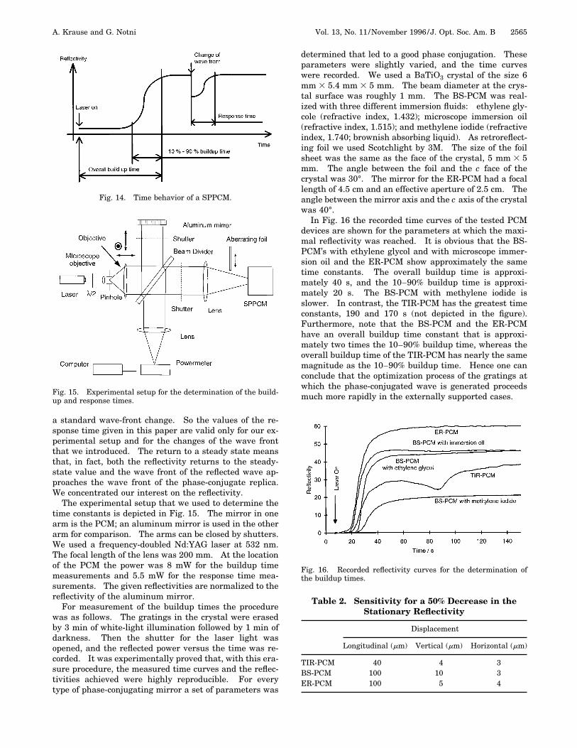
5. TIME BEHAVIORBesides the quality of phase conjugation the time behav-ior is important for the applicability of SPPCM in inter-ferometric systems.29 This includes the stability of thereflected power, which was discussed in Section 4, as wellas buildup and response times.In Fig. 14 the time behavior of a SPPCM is shown in
principle. We want to distinguish three time constantsdescribing it. First, there is the overall buildup time.This is the time from the beginning of the illuminationuntil the reflectivity reaches 90% of its steady-state value.Second, there is the 10–90% buildup time. This is theperiod in which the reflectivity rises from 10% to 90%.Third, there is the response time. This time constant de-scribes how fast the crystal responds to small changes ofthe entering wave. As a starting point we consider herea steady-state condition in which the wave front has beenentering the crystal for a long time. Then the shape ofthe wave front is instantaneously changed to anothersteady-state form. Such a change of the wave front istypical for the adjustment of the optical element undertest in a Fizeau interferometer.14 We define the responsetime as the time interval in which the power of the re-flected wave returns to 90% of the steady-state value.Note the difference between the photorefractive responsetime and the SPPCM response time defined here.We can clearly see that this definition of the response
time is valid only for a special experimental arrangementbecause the grating structure in any SPPCM will also de-pend on the entering wave front. Hence a universallyapplicable definition of the response time is difficult tofind. We would have to define a standard wave front and
A. Krause and G. Notni Vol. 13, No. 11 /November 1996 /J. Opt. Soc. Am. B 2565
a standard wave-front change. So the values of the re-sponse time given in this paper are valid only for our ex-perimental setup and for the changes of the wave frontthat we introduced. The return to a steady state meansthat, in fact, both the reflectivity returns to the steady-state value and the wave front of the reflected wave ap-proaches the wave front of the phase-conjugate replica.We concentrated our interest on the reflectivity.The experimental setup that we used to determine the
time constants is depicted in Fig. 15. The mirror in onearm is the PCM; an aluminum mirror is used in the otherarm for comparison. The arms can be closed by shutters.We used a frequency-doubled Nd:YAG laser at 532 nm.The focal length of the lens was 200 mm. At the locationof the PCM the power was 8 mW for the buildup timemeasurements and 5.5 mW for the response time mea-surements. The given reflectivities are normalized to thereflectivity of the aluminum mirror.For measurement of the buildup times the procedure
was as follows. The gratings in the crystal were erasedby 3 min of white-light illumination followed by 1 min ofdarkness. Then the shutter for the laser light wasopened, and the reflected power versus the time was re-corded. It was experimentally proved that, with this era-sure procedure, the measured time curves and the reflec-tivities achieved were highly reproducible. For everytype of phase-conjugating mirror a set of parameters was
Fig. 14. Time behavior of a SPPCM.
Fig. 15. Experimental setup for the determination of the build-up and response times.
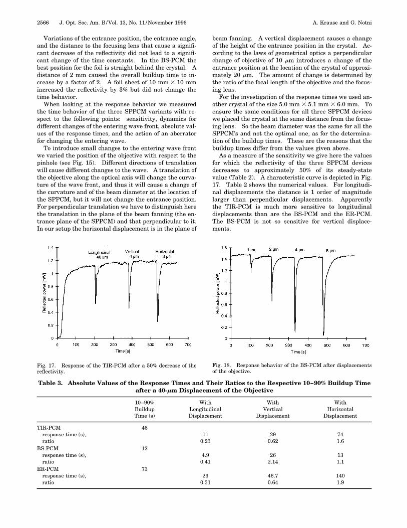
determined that led to a good phase conjugation. Theseparameters were slightly varied, and the time curveswere recorded. We used a BaTiO3 crystal of the size 6mm 3 5.4 mm 3 5 mm. The beam diameter at the crys-tal surface was roughly 1 mm. The BS-PCM was real-ized with three different immersion fluids: ethylene gly-cole (refractive index, 1.432); microscope immersion oil(refractive index, 1.515); and methylene iodide (refractiveindex, 1.740; brownish absorbing liquid). As retroreflect-ing foil we used Scotchlight by 3M. The size of the foilsheet was the same as the face of the crystal, 5 mm 3 5mm. The angle between the foil and the c face of thecrystal was 30°. The mirror for the ER-PCM had a focallength of 4.5 cm and an effective aperture of 2.5 cm. Theangle between the mirror axis and the c axis of the crystalwas 40°.In Fig. 16 the recorded time curves of the tested PCM
devices are shown for the parameters at which the maxi-mal reflectivity was reached. It is obvious that the BS-PCM’s with ethylene glycol and with microscope immer-sion oil and the ER-PCM show approximately the sametime constants. The overall buildup time is approxi-mately 40 s, and the 10–90% buildup time is approxi-mately 20 s. The BS-PCM with methylene iodide isslower. In contrast, the TIR-PCM has the greatest timeconstants, 190 and 170 s (not depicted in the figure).Furthermore, note that the BS-PCM and the ER-PCMhave an overall buildup time constant that is approxi-mately two times the 10–90% buildup time, whereas theoverall buildup time of the TIR-PCM has nearly the samemagnitude as the 10–90% buildup time. Hence one canconclude that the optimization process of the gratings atwhich the phase-conjugated wave is generated proceedsmuch more rapidly in the externally supported cases.
Fig. 16. Recorded reflectivity curves for the determination ofthe buildup times.
Table 2. Sensitivity for a 50% Decrease in theStationary Reflectivity
Displacement
Longitudinal (mm) Vertical (mm) Horizontal (mm)
TIR-PCM 40 4 3BS-PCM 100 10 3ER-PCM 100 5 4
2566 J. Opt. Soc. Am. B/Vol. 13, No. 11 /November 1996 A. Krause and G. Notni
Variations of the entrance position, the entrance angle,and the distance to the focusing lens that cause a signifi-cant decrease of the reflectivity did not lead to a signifi-cant change of the time constants. In the BS-PCM thebest position for the foil is straight behind the crystal. Adistance of 2 mm caused the overall buildup time to in-crease by a factor of 2. A foil sheet of 10 mm 3 10 mmincreased the reflectivity by 3% but did not change thetime behavior.When looking at the response behavior we measured
the time behavior of the three SPPCM variants with re-spect to the following points: sensitivity, dynamics fordifferent changes of the entering wave front, absolute val-ues of the response times, and the action of an aberratorfor changing the entering wave.To introduce small changes to the entering wave front
we varied the position of the objective with respect to thepinhole (see Fig. 15). Different directions of translationwill cause different changes to the wave. A translation ofthe objective along the optical axis will change the curva-ture of the wave front, and thus it will cause a change ofthe curvature and of the beam diameter at the location ofthe SPPCM, but it will not change the entrance position.For perpendicular translation we have to distinguish herethe translation in the plane of the beam fanning (the en-trance plane of the SPPCM) and that perpendicular to it.In our setup the horizontal displacement is in the plane of
Fig. 17. Response of the TIR-PCM after a 50% decrease of thereflectivity.
beam fanning. A vertical displacement causes a changeof the height of the entrance position in the crystal. Ac-cording to the laws of geometrical optics a perpendicularchange of objective of 10 mm introduces a change of theentrance position at the location of the crystal of approxi-mately 20 mm. The amount of change is determined bythe ratio of the focal length of the objective and the focus-ing lens.For the investigation of the response times we used an-
other crystal of the size 5.0 mm 3 5.1 mm 3 6.0 mm. Toensure the same conditions for all three SPPCM deviceswe placed the crystal at the same distance from the focus-ing lens. So the beam diameter was the same for all theSPPCM’s and not the optimal one, as for the determina-tion of the buildup times. These are the reasons that thebuildup times differ from the values given above.As a measure of the sensitivity we give here the values
for which the reflectivity of the three SPPCM devicesdecreases to approximately 50% of its steady-statevalue (Table 2). A characteristic curve is depicted in Fig.17. Table 2 shows the numerical values. For longitudi-nal displacements the distance is 1 order of magnitudelarger than perpendicular displacements. Apparentlythe TIR-PCM is much more sensitive to longitudinaldisplacements than are the BS-PCM and the ER-PCM.The BS-PCM is not so sensitive for vertical displace-ments.
Fig. 18. Response behavior of the BS-PCM after displacementsof the objective.
Table 3. Absolute Values of the Response Times and Their Ratios to the Respective 10–90% Buildup Timeafter a 40-mm Displacement of the Objective
10–90%BuildupTime (s)
WithLongitudinalDisplacement
WithVertical
Displacement
WithHorizontal
Displacement
TIR-PCMresponse time (s),ratio
46110.23
290.62
741.6
BS-PCMresponse time (s),ratio
124.90.41
262.14
131.1
ER-PCMresponse time (s),ratio
73230.31
46.70.64
1401.9

A. Krause and G. Notni Vol. 13, No. 11 /November 1996 /J. Opt. Soc. Am. B 2567
Table 4. Absolute Values of the Response Time and Their Ratios to the Respective 10–90% Buildup Timefor the Translation of an Aberrating Foil
10–90%BuildupTime (s)
Displacement of the Foil (mm)
0.025 0.05 0.1 0.2
TIR-PCMresponse time (s),ratio
216150.07
250.11
1450.67
1510.70
BS-PCMresponse time (s),ratio
34160.47
150.44
220.65
250.74
ER-PCMresponse time (s),ratio
180130.07
430.24
650.36
680.38
For the determination of the response times we took,with regard to practical applications, the amount of 40mm for the translations in all the directions. Figure 18shows an example of the response behavior of the BS-PCM after horizontal displacements of the objective. Theresponse times are given in Table 3. These investiga-tions show the astonishing fact that the response time canbe larger than the buildup time.In the case of the buildup time the initial condition is
characterized by a homogeneous crystal without gratings.After the intermediate state of beam fanning the finalstate is characterized by a set of gratings that producesthe phase-conjugate wave. In comparison to this the ini-tial state of the response time is characterized by a set ofphase-conjugating gratings. Because of the small changeof the entering wave one expects that the final state (dis-tribution and strength of the gratings) is similar to theinitial state. So one would also expect the response timeto be smaller than the buildup time. Response timesthat are larger than the buildup time occur only when thechange of the entering wave is related to a change of theentrance position.When the objective is moved the introduced change of
the wave front is always related to the change of the en-trance position or beam diameter. To see the responsebehavior without this effect, we introduced an aberratingdiffuse plastic foil directly in front of the SPPCM. Theresults are as follows (Table 4). Without any change ofthe entrance position the response time even for largetranslations of the plastic foil (0.4 mm) is smaller thanthe 10–90% buildup time. So we prove here that thelonger response times for perpendicular translations ofthe objective are related to the change of the entrance po-sition.Summarizing these investigations, we can say that the
response behavior of the SPPCM’s is different for changesof the wave that also cause a change of the entrance po-sition and for changes in which only the shape of the wavefront is altered. In the case in which only the shape ofthe wave front is altered, the response time is smallerthan the buildup time. When the entrance position ischanged, the response time can be larger than thebuildup time. In general, the characteristic response be-havior does not depend on the type of the SPPCM. Onlythe numerical values of the response times are differentfor the different types of the SPPCM.
6. SUMMARYInterferometric systems with self-pumped phase-conjugate mirrors (SPPCM’s) offer good possibilities forthe determination of the quality of optical elements (e.g.,lenses and mirrors) and for the measurement of opticalwave fronts. In addition, because of the aberration cor-rection of unknown wave fronts the application is espe-cially recommended in systems in which classical opticalsystems reach their limits, such as the testing ofaspherical surfaces. We have compared the achievableaccuracy of a Twyman–Green interferometer for threedifferentSPPCM types: the TIR-PCM, which works without anexternal support, and the BS-PCM and the ER-PCM,which both work with an external support. These mea-surements gave evidence that SPPCM’s are able to cor-rect aberrations introduced by optical elements, but theexternally supported types showed higher phase fluctua-tions of the reflected wave. So for very-high-accuracymeasurements (rms value of the reproducibility, 1 nm)only the TIR-PCM is recommended. The investigation ofthe time behavior gave the following results. The exter-nally supported SPPCM’s have for nearly the same ex-perimental conditions smaller overall and 10–90%buildup times than the TIR-PCM. For all three SPPCMtypes the response time has the same order of magnitudeas the respective 10–90% buildup time. So, in applica-tions in which a faster time behavior is important, the ex-ternally supported types are better suited.
ACKNOWLEDGMENTSParts of this research were supported by the DeutscheForschungsgemeinschaft (Sonderforschungsbereich 225,project D 13) and by the Bundesministerium fur Fors-chung und Technologie (grant 13 N 6061). We thank M.Palme for help with the evaluation of the CGH and S.Sochava for help with the determination of the responsetimes.
Address correspondence to A. Krause (e-mail:[email protected]).

2568 J. Opt. Soc. Am. B/Vol. 13, No. 11 /November 1996 A. Krause and G. Notni
REFERENCES1. P. Gunther and J.-P. Huignard, eds., Photorefractive Mate-
rials and Their Applications I and II, Vols. 61 and 62 ofTopics in Applied Physics (Springer-Verlag, Berlin, 1989).
2. F. M. Davidson, ed., Selected Papers on Photorefractive Ma-terials, Vol. MS86 of SPIE Milestone Series (1994).
3. M. Gower and D. Proch, eds., Optical Phase Conjugation(Springer-Verlag, Berlin, 1994).
4. M. D. Ewbank and P. Yeh, ‘‘Fidelity of passive conjugators,’’in Nonlinear Optics and Applications, P. A. Yeh, ed., Proc.SPIE 613, 11–17 (1986).
5. D. M. Pepper, ‘‘Nonlinear optical phase conjugation,’’ in La-ser Handbook, M. L. Stitch and M. Bass, eds. (Elsevier, Am-sterdam, 1985), Vol. 4.
6. J. Feinberg, ‘‘Interferometer with a self-pumped phase-conjugating mirror,’’ Opt. Lett. 8, 569–571 (1983).
7. J. P. Herriau, A. Deboulbe, and J.-P. Huignard, ‘‘Nonde-structive testing using real time holographic interferometryin B.S.O. crystals,’’ in Industrial Applications of LaserTechnology, W. F. Fagan, ed., Proc. SPIE 398, 123–129(1983).
8. J. Feinberg, ‘‘Self-pumped, continuous-wave phase conjuga-tor using internal reflection,’’ Opt. Lett. 7, 486–488 (1982).
9. R. A. Mullen, D. J. Vickers, L. West, and D. M. Pepper,‘‘Phase conjugation by stimulated photorefractive scatter-ing using a retroreflected seeding beam,’’ J. Opt. Soc. Am. B9, 1726–1734 (1992).
10. H. Rehn and R. Kowarschik, ‘‘Experimental investigationsof the external self-pumped phase conjugate mirror,’’ Opt.Commun. 109, 155–162 (1994).
11. D. Malacara, ed., Optical Shop Testing (Wiley, New York,1978).
12. P. Hariharan, ed., Selected Papers on Interferometry, Vol.MS28 of SPIE Milestone Series (1991).
13. R. P. Shukla, M. Dokhanian, P. Venkateswarlu, and M. C.George, ‘‘Phase conjugate Twyman–Green interferometerfor testing optical surfaces and lenses and for measuring re-fractive indices of liquid or solid transparent materials,’’Opt. Commun. 78, 407–415 (1990).
14. D. J. Gauthier, R. W. Boyd, R. K. Junquist, J. B. Lisson,and L. L. Voci, ‘‘Phase conjugate Fizeau interferometer,’’Opt. Lett. 14, 323–325 (1989).
15. G. Notni, L. Wenke, and R. Kowarschik, ‘‘Phase-conjugateFizeau-interferometer for testing optical surfaces,’’ in Pho-torefractive Materials, Effects, and Devices, Vol. 14 of 1991OSA Technical Digest Series (Optical Society of America,Washington, D.C., 1991), postdeadline papers 1–4.
16. B. Dorband and H. J. Tiziani, ‘‘Testing aspheric surfaceswith computer generated holograms: analysis of adjust-
ment and shape errors,’’ Appl. Opt. 24, 2604–2611 (1985).17. A. Handojo and J. de Hong, ‘‘Interferometer for optical test-
ing with computer-generated holograms,’’ Appl. Opt. 16,546–547 (1977).
18. H. P. Stahl, ‘‘Aspheric surface testing techniques,’’ in Opti-cal Testing and Metrology III: Recent Advances in Indus-trial Optical Inspection, C. Grover, ed., Proc. SPIE 1332,66–76 (1990).
19. G. Notni, L. Wenke, and R. Kowarschik, ‘‘Phase-conjugateinterferometers for testing optical surfaces,’’ in 16th Con-gress of the International Commission for Optics: Opticsas a Key to High Technology, G. Lupkovic, ed., Proc. SPIE1983, 919–920 (1993).
20. R. P. Shukla, M. Dokhanian, P. Venkateswarlu, and M. C.George, ‘‘Phase-conjugate Twyman Green interferometerfor testing conicoidal surfaces,’’ in Optical Testing and Me-trology III: Recent Advances in Industrial Optical Inspec-tion, C. Grover, ed., Proc. SPIE 1332, 274–286 (1990).
21. W. D. Shen and L. Ding-ten, ‘‘Profile measurements of cy-lindrical surfaces,’’ Appl. Opt. 32, 1060–1064 (1993).
22. T. Blumel, K-E. ElXner, R. Kafka, G. Schulz, and A. Vogel,‘‘Absolute testing of cylindrical surfaces,’’ in Interferometry’94: New Techniques and Analysis in Optical Measure-ments, M. Kujawinska and K. Petorski, eds., Proc SPIE2340, 250–257 (1994).
23. G. J. Salamo, B. D. Monson, W. W. Clark III, G. L. Wood, E.J. Sharp, and R. R. Neurgaonkar, ‘‘Improved photorefrac-tive time response using a cylindrical lens,’’ Appl. Opt. 30,1847–1854 (1991).
24. M. Takeda, H. Ina, and S. Kobayashi, ‘‘Fourier-transformmethod of fringe-pattern analysis for computer-based to-pography and interferometry,’’ J. Opt. Soc. Am. 72, 156–160 (1982).
25. J. Schwider, ‘‘Advanced evaluation techniques in interfer-ometry,’’ in Progress in Optics, E. Wolf, ed. (North-Holland,Amsterdam, 1990), Vol. 28, pp. 271–359.
26. Y. Tomita, R. Yahalom, and A. Yariv, ‘‘Phase shift and crosstalk of a self-pumped phase-conjugate mirror,’’ Opt. Com-mun. 73, 413–419 (1989).
27. Y. Ishii and I. Uehira, ‘‘Laser-diode phase-shifting interfer-ometry with a self-pumped phase-conjugate mirror,’’ Opt.Lett. 18, 1459–1461 (1993).
28. G. Notni, R. Schenderlein, and L. Wenke, ‘‘Ellipse fittingtechnique for phase shifter calibration,’’ in Fringe ’93, W.Juptner and W. Osten, eds. (Akademie-Verlag, Berlin,1993), pp. 91–93.
29. A. Krause, G. Notni, and L. Wenke, ‘‘Investigation of thetime behaviour of different self-pumped phase-conjugatingmirrors for the application in interferometric systems,’’Opt. Mater. 4, 386–391 (1995).


![The Conjugate Gradient Method...Conjugate Gradient Algorithm [Conjugate Gradient Iteration] The positive definite linear system Ax = b is solved by the conjugate gradient method](https://img.pdfslide.us/doc/110x75/5e95c1e7f0d0d02fb330942a/the-conjugate-gradient-method-conjugate-gradient-algorithm-conjugate-gradient.jpg)