Embed Size (px)
Citation preview
Stainless
Cast Iron
Urban
CablepitTechnical Information MEADRAIN® Linear Drainage Hydraulic calculations
When drawing up an individual design based on the given requirements, MEA drains solutions provide quick, reliable and economical drainage of surface water. Whether in the public, industrial or private sector, linear drainage is the optimal solution as water can drain into the installed channel along the entire length.
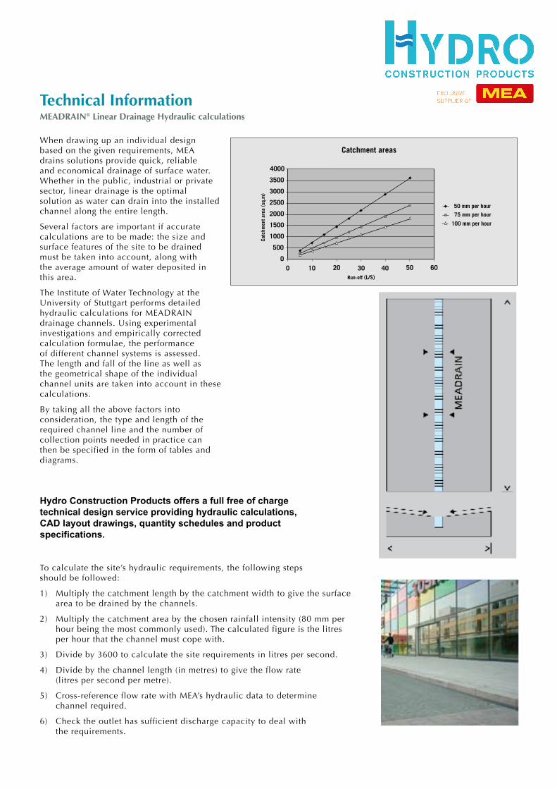
Several factors are important if accurate calculations are to be made: the size and surface features of the site to be drained must be taken into account, along with the average amount of water deposited in this area.
The Institute of Water Technology at the University of Stuttgart performs detailed hydraulic calculations for MEADRAIN drainage channels. Using experimental investigations and empirically corrected calculation formulae, the performance of different channel systems is assessed. The length and fall of the line as well as the geometrical shape of the individual channel units are taken into account in these calculations.
By taking all the above factors into consideration, the type and length of the required channel line and the number of collection points needed in practice can then be specified in the form of tables and diagrams.
MEADRAIN ® L inear Dra inageHydraul ic ca lcula t ions -
14
When drawing up an individualdesign based on the givenrequirements, MEA drains solutionsprovide quick, reliable andeconomical drainage of surface water.Whether in the public, industrial orprivate sector, linear drainage is theoptimal solution as water can draininto the installed channel along theentire length.Several factors are important ifaccurate calculations are to be made:the size and surface features of thesite to be drained must be taken intoaccount, along with the averageamount of water deposited in thisarea.The Institute of Water Technology atthe University of Stuttgart performsdetailed hydraulic calculations forMEADRAIN drainage channels. Usingexperimental investigations andempirically corrected calculationformulae, the performance of differentchannel systems is assessed. Thelength and fall of the line as well asthe geometrical shape of theindividual channel units are taken intoaccount in these calculations.By taking all the above factors intoconsideration, the type and length ofthe required channel line and thenumber of collection points needed inpractice can then be specified in theform of tables and diagrams.
MEA offer a full free of chargetechnical design service providinghydraulic calculations, CAD layoutdrawings, quantity schedules andproduct specifications.
To calculate the site’s hydraulic requirements, the following steps should be followed:1) Multiply the catchment length by the catchment width to give the surface area
to be drained by the channels.2) Multiply the catchment area by the chosen rainfall intensity (80 mm per hour
being the most commonly used). The calculated figure is the litres per hour that the channel must cope with.
3) Divide by 3600 to calculate the site requirements in litres per second.4) Divide by the channel length (in metres) to give the flow rate
(litres per second per metre).5) Cross-reference flow rate with MEA’s hydraulic data to determine
channel required.6) Check the outlet has sufficient discharge capacity to deal with the
requirements.
Catchment areas
Catc
hmen
t are
a (s
q.m
)
4000
3500
2500
3000
2000
1500
1000
500
00 10 20 30 40 50 60
Run-off (L/S)
50 mm per hour
75 mm per hour
100 mm per hour
P0210 MEADRAIN Catalogue
To calculate the site’s hydraulic requirements, the following steps should be followed:
1) Multiply the catchment length by the catchment width to give the surface area to be drained by the channels.
2) Multiply the catchment area by the chosen rainfall intensity (80 mm per hour being the most commonly used). The calculated figure is the litres per hour that the channel must cope with.
3) Divide by 3600 to calculate the site requirements in litres per second.
4) Divide by the channel length (in metres) to give the flow rate (litres per second per metre).
5) Cross-reference flow rate with MEA’s hydraulic data to determine channel required.
6) Check the outlet has sufficient discharge capacity to deal withthe requirements.
MEADRAIN ® L inear Dra inageHydraul ic ca lcula t ions -
14
When drawing up an individualdesign based on the givenrequirements, MEA drains solutionsprovide quick, reliable andeconomical drainage of surface water.Whether in the public, industrial orprivate sector, linear drainage is theoptimal solution as water can draininto the installed channel along theentire length.Several factors are important ifaccurate calculations are to be made:the size and surface features of thesite to be drained must be taken intoaccount, along with the averageamount of water deposited in thisarea.The Institute of Water Technology atthe University of Stuttgart performsdetailed hydraulic calculations forMEADRAIN drainage channels. Usingexperimental investigations andempirically corrected calculationformulae, the performance of differentchannel systems is assessed. Thelength and fall of the line as well asthe geometrical shape of theindividual channel units are taken intoaccount in these calculations.By taking all the above factors intoconsideration, the type and length ofthe required channel line and thenumber of collection points needed inpractice can then be specified in theform of tables and diagrams.
MEA offer a full free of chargetechnical design service providinghydraulic calculations, CAD layoutdrawings, quantity schedules andproduct specifications.
To calculate the site’s hydraulic requirements, the following steps should be followed:1) Multiply the catchment length by the catchment width to give the surface area
to be drained by the channels.2) Multiply the catchment area by the chosen rainfall intensity (80 mm per hour
being the most commonly used). The calculated figure is the litres per hour that the channel must cope with.
3) Divide by 3600 to calculate the site requirements in litres per second.4) Divide by the channel length (in metres) to give the flow rate
(litres per second per metre).5) Cross-reference flow rate with MEA’s hydraulic data to determine
channel required.6) Check the outlet has sufficient discharge capacity to deal with the
requirements.
Catchment areas
Catc
hmen
t are
a (s
q.m
)
4000
3500
2500
3000
2000
1500
1000
500
00 10 20 30 40 50 60
Run-off (L/S)
50 mm per hour
75 mm per hour
100 mm per hour
P0210 MEADRAIN Catalogue
Hydro Construction Products offers a full free of charge technical design service providing hydraulic calculations, CAD layout drawings, quantity schedules and product specifications.
Stainless
Cast Iron
Urban
CablepitTechnical Information MEADRAIN® 1000 Channel Run Information
MEADRAIN® 1000Channel run informat ion
15
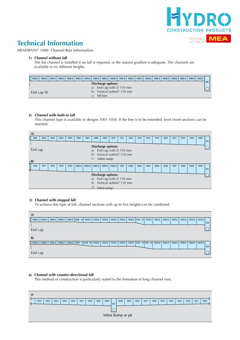
Discharge options:a) End cap with ∅ 110 mmb) Vertical outlet ∅ 110 mmc) Silt box
1) Channel without fallThe flat channel is installed if no fall is required, or the natural gradient is adequate. The channels are available in six different heights.
Discharge options:a) End cap with ∅ 110 mmb) Vertical outlet ∅ 110 mmc) Inline sump
Discharge options:a) End cap with ∅ 110 mmb) Vertical outlet ∅ 110 mmc)
A)
B)
2) Channel with built-in fallThis channel type is available in designs 1001-1030. If the line is to be extended, level invert sections can be inserted.
End cap SE
End cap
A)
B)
3) Channel with stepped fallTo achieve this type of fall, channel sections with up to five heights can be combined.
End cap
End cap
a)
4) Channel with counter-directional fallThis method of construction is particularly suited to the formation of long channel runs.
Inline Sump or pit
P0210 MEADRAIN Catalogue
Meadrain Catalogue - Hydro 0408.15 15 27/5/08 10:44:17 AM
Inline sump