Embed Size (px)
Citation preview
Land Rover Revision Date: September 2004 Page 1 of 84
ON-BOARD DIAGNOSTICS ME7.2 Engine Management
Vehicle Coverage: New Range Rover 2005 MY
Land Rover Revision Date: September 2004 Page 2 of 84
1 Contents 1 Contents 2 2 Introduction 5
2.1 Inputs and Outputs 5 3 Mode $06 Data 7 4 OBD Drive Cycle Information 10 5 On Board Monitoring 12
5.1 Catalyst Monitoring 12 5.1.1 Description 12 5.1.2 Monitoring Structure 13 5.1.3 Block Diagram of System Operation 15 5.1.4 Drive Cycle Information 16
5.2 Misfire Monitoring 17 5.2.1 Description 17 5.2.2 Monitoring Structure 18 5.2.3 Fault Processing for Emissions Relevant Misfire 21 5.2.4 Drive Cycle Information 22
5.3 Secondary Air Injection System Monitoring 23 5.3.1 Description 23 Monitoring Structure 24 5.3.3 Drive Cycle Information 25
5.4 Evaporative Emission System Leak Measurement 26 5.4.1 Description of Leak Measurement 26 Monitoring Structure 29 5.4.3 Description of Evaporative Emission Canister Purge System Flow Check 34 5.4.4 Monitoring Structure 34 5.4.5 Drive Cycle Information 39
5.5 Fuel System Monitoring 40 5.5.1 Description 40 Monitoring Structure 42 5.5.3 Drive Cycle Information 44
5.6 Oxygen Sensor Monitoring 45 5.6.1 Description 45 Monitoring Structure 46 5.6.3 Oxygen Sensor Heater Monitoring Description 48 5.6.4 Oxygen Sensor Heater Monitoring Structure 49 5.6.5 Drive Cycle Information 53
5.7 Thermostat Monitoring 55 Description 55 Monitoring Structure 56
Land Rover Revision Date: September 2004 Page 3 of 84
5.7.3 Drive Cycle Information 59 5.8 Positive Crankcase Ventilation (PCV) System Monitoring 60
5.8.1 Description 60 5.8.2 Drive Cycle Information 62
5.9 Crankshaft Speed and Position Sensor 63 5.9.1 Description 63 5.9.2 Drive Cycle Information 63
5.10 Camshaft Position Control Interface (VANOS) 64 5.10.1 Description 64 5.10.2 Drive Cycle Information 65
5.11 Engine Coolant Temperature Sensor 66 5.11.1 Description 66 5.11.2 Drive Cycle Information 67
5.13 Mass Airflow Sensor & Intake Air Temperature Sensor 68 5.13.1 Mass Airflow Sensor Description 68 5.13.2 Drive Cycle Information 68 5.13.3 Intake Air Temperature Sensor Description 69 5.13.4 Drive Cycle Information 70
5.14 Knock Sensor 71 5.14.1 Description 71 5.14.2 Drive Cycle Information 71
5.15 Fuel Tank Level Sensor 73 5.15.1 Description 73 5.15.2 Drive Cycle Information 73
5.16 Throttle Position Sensor 74 5.16.1 Description 74 5.16.2 Drive Cycle Information 75
5.17 Engine Control Module Self Test 76 5.17.1 Description 76 5.17.2 Drive Cycle Information 76
5.18 Ambient Air Temperature Interface 77 5.18.1 Description 77 5.18.2 Drive Cycle Information 77
5.19 Vehicle Speed Interface 78 5.19.1 Description 78 5.19.2 Drive Cycle Information 78
5.20 Transfer Box Control Module Interface 79 5.20.1 Description 79 5.20.2 Drive Cycle Information 79
5.21 CAN System 80 5.21.1 Description 80 5.21.2 Drive Cycle Information 80
Land Rover Revision Date: September 2004 Page 4 of 84
5.22 Fuel Injectors 81 5.22.1 Description 81 5.22.2 Drive Cycle information 81
5.23 Idle Speed Control Actuator 83 5.23.1 Description 83 5.23.2 Drive Cycle Information 83
5.24 Electronic Throttle Interface 84 5.24.1 Description 84 5.24.2 Drive Cycle Information 84
Land Rover Revision Date: September 2004 Page 5 of 84
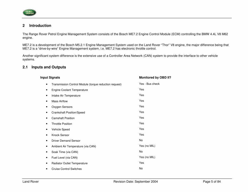
2 Introduction The Range Rover Petrol Engine Management System consists of the Bosch ME7.2 Engine Control Module (ECM) controlling the BMW 4.4L V8 M62 engine. ME7.2 is a development of the Bosch M5.2.1 Engine Management System used on the Land Rover “Thor” V8 engine, the major difference being that ME7.2 is a “drive-by-wire” Engine Management system, i.e. ME7.2 has electronic throttle control. Another significant system difference is the extensive use of a Controller Area Network (CAN) system to provide the interface to other vehicle systems.
2.1 Inputs and Outputs
Input Signals Monitored by OBD II?
• Transmission Control Module (torque reduction request) Yes - Bus check
• Engine Coolant Temperature Yes
• Intake Air Temperature Yes
• Mass Airflow Yes
• Oxygen Sensors Yes
• Crankshaft Position/Speed Yes
• Camshaft Position Yes
• Throttle Position Yes
• Vehicle Speed Yes
• Knock Sensor Yes
• Driver Demand Sensor No
• Ambient Air Temperature (via CAN) Yes (no MIL)
• Soak Time (via CAN) No
• Fuel Level (via CAN) Yes (no MIL)
• Radiator Outlet Temperature Yes
• Cruise Control Switches No
Land Rover Revision Date: September 2004 Page 6 of 84
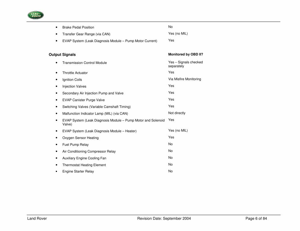
• Brake Pedal Position No
• Transfer Gear Range (via CAN) Yes (no MIL)
• EVAP System (Leak Diagnosis Module – Pump Motor Current) Yes
Output Signals Monitored by OBD II?
• Transmission Control Module Yes – Signals checked separately
• Throttle Actuator Yes
• Ignition Coils Via Misfire Monitoring
• Injection Valves Yes
• Secondary Air Injection Pump and Valve Yes
• EVAP Canister Purge Valve Yes
• Switching Valves (Variable Camshaft Timing) Yes
• Malfunction Indicator Lamp (MIL) (via CAN) Not directly
• EVAP System (Leak Diagnosis Module – Pump Motor and Solenoid Valve)
Yes
• EVAP System (Leak Diagnosis Module – Heater) Yes (no MIL)
• Oxygen Sensor Heating Yes
• Fuel Pump Relay No
• Air Conditioning Compressor Relay No
• Auxiliary Engine Cooling Fan No
• Thermostat Heating Element No
• Engine Starter Relay No
Land Rover Revision Date: September 2004 Page 7 of 84
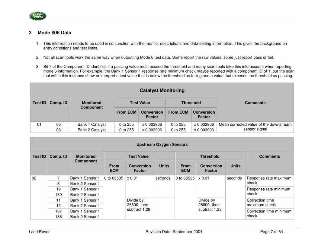
3 Mode $06 Data
1. This information needs to be used in conjunction with the monitor descriptions and data setting information. This gives the background on entry conditions and test limits.
2. Not all scan tools work the same way when outputting Mode 6 test data. Some report the raw values, some just report pass or fail.
3. Bit 7 of the Component ID identifies if a passing value must exceed the threshold and many scan tools take this into account when reporting
mode 6 information. For example, the Bank 1 Sensor 1 response rate minimum check maybe reported with a component ID of 1, but the scan tool will in this instance show or interpret a test value that is below the threshold as failing and a value that exceeds the threshold as passing.
Catalyst Monitoring
Test Value Threshold Test ID Comp. ID Monitored Component
From ECM Conversion Factor
From ECM Conversion Factor
Comments
05 Bank 1 Catalyst 0 to 255 x 0.003906 0 to 255 x 0.003906 01 06 Bank 2 Catalyst 0 to 255 x 0.003906 0 to 255 x 0.003906
Mean corrected value of the downstream sensor signal
Upstream Oxygen Sensors
Test Value Threshold Test ID Comp. ID Monitored Component
From ECM
Conversion Factor
Units From ECM
Conversion Factor
Units
Comments
7 Bank 1 Sensor 1 8 Bank 2 Sensor 1
Response rate maximum check
19 Bank 1 Sensor 1 130 Bank 2 Sensor 1
x 0.01 seconds x 0.01
Response rate minimum check
11 Bank 1 Sensor 1 12 Bank 2 Sensor 1
Correction time maximum check
137 Bank 1 Sensor 1
02
138 Bank 2 Sensor 1
0 to 65535
Divide by 25600, then subtract 1.28
0 to 65535
Divide by 25600, then subtract 1.28
seconds
Correction time minimum check
Land Rover Revision Date: September 2004 Page 8 of 84
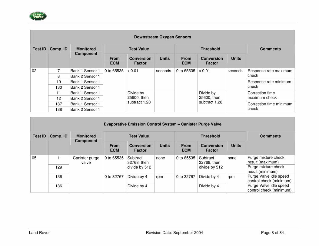
Downstream Oxygen Sensors
Test Value Threshold Test ID Comp. ID Monitored Component
From ECM
Conversion Factor
Units From ECM
Conversion Factor
Units
Comments
7 Bank 1 Sensor 1 8 Bank 2 Sensor 1
Response rate maximum check
19 Bank 1 Sensor 1 130 Bank 2 Sensor 1
x 0.01 seconds x 0.01
Response rate minimum check
11 Bank 1 Sensor 1 12 Bank 2 Sensor 1
Correction time maximum check
137 Bank 1 Sensor 1
02
138 Bank 2 Sensor 1
0 to 65535
Divide by 25600, then subtract 1.28
0 to 65535
Divide by 25600, then subtract 1.28
seconds
Correction time minimum check
Evaporative Emission Control System – Canister Purge Valve
Test Value Threshold Test ID Comp. ID Monitored Component
From ECM
Conversion Factor
Units From ECM
Conversion Factor
Units
Comments
1 Purge mixture check result (maximum)
129
0 to 65535 Subtract 32768, then divide by 512
none 0 to 65535 Subtract 32768, then divide by 512
none
Purge mixture check result (minimum)
136 Divide by 4 Divide by 4 Purge Valve idle speed control check (minimum)
05
136
Canister purge valve
0 to 32767
Divide by 4
rpm 0 to 32767
Divide by 4
rpm
Purge Valve idle speed control check (minimum)
Land Rover Revision Date: September 2004 Page 9 of 84
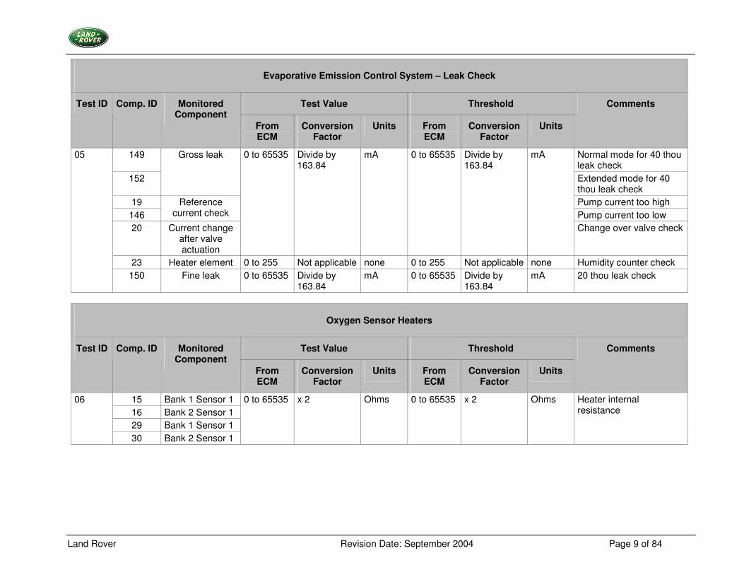
Evaporative Emission Control System – Leak Check
Test Value Threshold Test ID Comp. ID Monitored Component
From ECM
Conversion Factor
Units From ECM
Conversion Factor
Units
Comments
149 Normal mode for 40 thou leak check
152
Gross leak
Extended mode for 40 thou leak check
19 Pump current too high 146
Reference current check Pump current too low
20 Current change after valve actuation
0 to 65535 Divide by 163.84
mA 0 to 65535 Divide by 163.84
mA
Change over valve check
23 Heater element 0 to 255 Not applicable none 0 to 255 Not applicable none Humidity counter check
05
150 Fine leak 0 to 65535 Divide by 163.84
mA 0 to 65535 Divide by 163.84
mA 20 thou leak check
Oxygen Sensor Heaters
Test Value Threshold Test ID Comp. ID Monitored Component
From ECM
Conversion Factor
Units From ECM
Conversion Factor
Units
Comments
15 Bank 1 Sensor 1 16 Bank 2 Sensor 1 29 Bank 1 Sensor 1
06
30 Bank 2 Sensor 1
0 to 65535 x 2 Ohms 0 to 65535 x 2 Ohms Heater internal resistance
Land Rover Revision Date: September 2004 Page 10 of 84
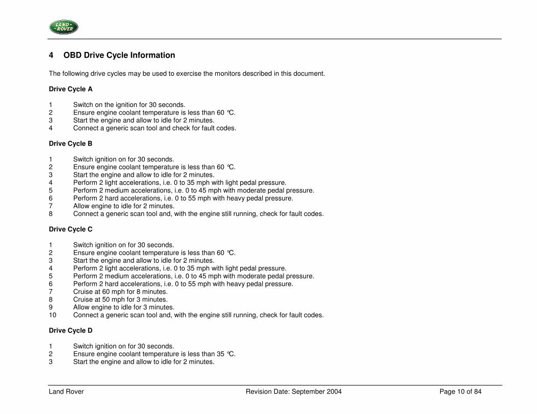
4 OBD Drive Cycle Information The following drive cycles may be used to exercise the monitors described in this document. Drive Cycle A 1 Switch on the ignition for 30 seconds. 2 Ensure engine coolant temperature is less than 60 °C. 3 Start the engine and allow to idle for 2 minutes. 4 Connect a generic scan tool and check for fault codes. Drive Cycle B 1 Switch ignition on for 30 seconds. 2 Ensure engine coolant temperature is less than 60 °C. 3 Start the engine and allow to idle for 2 minutes. 4 Perform 2 light accelerations, i.e. 0 to 35 mph with light pedal pressure. 5 Perform 2 medium accelerations, i.e. 0 to 45 mph with moderate pedal pressure. 6 Perform 2 hard accelerations, i.e. 0 to 55 mph with heavy pedal pressure. 7 Allow engine to idle for 2 minutes. 8 Connect a generic scan tool and, with the engine still running, check for fault codes. Drive Cycle C 1 Switch ignition on for 30 seconds. 2 Ensure engine coolant temperature is less than 60 °C. 3 Start the engine and allow to idle for 2 minutes. 4 Perform 2 light accelerations, i.e. 0 to 35 mph with light pedal pressure. 5 Perform 2 medium accelerations, i.e. 0 to 45 mph with moderate pedal pressure. 6 Perform 2 hard accelerations, i.e. 0 to 55 mph with heavy pedal pressure. 7 Cruise at 60 mph for 8 minutes. 8 Cruise at 50 mph for 3 minutes. 9 Allow engine to idle for 3 minutes. 10 Connect a generic scan tool and, with the engine still running, check for fault codes. Drive Cycle D 1 Switch ignition on for 30 seconds. 2 Ensure engine coolant temperature is less than 35 °C. 3 Start the engine and allow to idle for 2 minutes.
Land Rover Revision Date: September 2004 Page 11 of 84
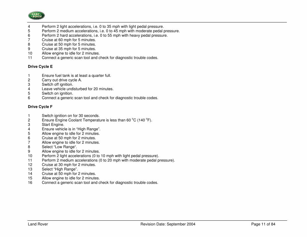
4 Perform 2 light accelerations, i.e. 0 to 35 mph with light pedal pressure. 5 Perform 2 medium accelerations, i.e. 0 to 45 mph with moderate pedal pressure. 6 Perform 2 hard accelerations, i.e. 0 to 55 mph with heavy pedal pressure. 7 Cruise at 60 mph for 5 minutes. 8 Cruise at 50 mph for 5 minutes. 9 Cruise at 35 mph for 5 minutes. 10 Allow engine to idle for 2 minutes. 11 Connect a generic scan tool and check for diagnostic trouble codes. Drive Cycle E 1 Ensure fuel tank is at least a quarter full. 2 Carry out drive cycle A. 3 Switch off ignition. 4 Leave vehicle undisturbed for 20 minutes. 5 Switch on ignition. 6 Connect a generic scan tool and check for diagnostic trouble codes. Drive Cycle F 1 Switch ignition on for 30 seconds. 2 Ensure Engine Coolant Temperature is less than 60 oC (140 oF). 3 Start Engine. 4 Ensure vehicle is in “High Range”. 5 Allow engine to idle for 2 minutes. 6 Cruise at 50 mph for 2 minutes. 7 Allow engine to idle for 2 minutes. 8 Select “Low Range“. 9 Allow engine to idle for 2 minutes. 10 Perform 2 light accelerations (0 to 10 mph with light pedal pressure). 11 Perform 2 medium accelerations (0 to 20 mph with moderate pedal pressure). 12 Cruise at 30 mph for 2 minutes. 13 Select “High Range”. 14 Cruise at 50 mph for 2 minutes. 15 Allow engine to idle for 2 minutes. 16 Connect a generic scan tool and check for diagnostic trouble codes.
Land Rover Revision Date: September 2004 Page 12 of 84
5 On Board Monitoring
5.1 Catalyst Monitoring
5.1.1 Description Catalyst monitoring is based on the monitoring of oxygen storage capability. The (non-linear) correlation between conversion efficiency and storage capability has been shown in various investigations. The engine closed loop feedback control results in regular lambda (normalised air/fuel ratio) oscillations in the exhaust gas. These oscillations are damped by the oxygen storage activity of the catalyst. The amplitude of the remaining lambda oscillations downstream of the catalyst indicates the storage capability. The monitoring function compares the signal amplitudes obtained from the downstream oxygen sensors with modelled signal amplitudes. The modelled signal amplitudes are derived from a model of a borderline catalyst. If the measured amplitudes exceed those of the model, then the catalyst is considered to be defective. Unlike the previous catalyst monitoring function, this operates over a single range of engine speed and load. The monitoring function can be broken down into the following sub-sections: -
• Computation of the downstream oxygen sensor signal amplitudes
• Modelling of a borderline catalyst and the downstream oxygen sensor signal amplitudes
• Signal evaluation
• Fault processing
• Function enable criteria
Land Rover Revision Date: September 2004 Page 13 of 84
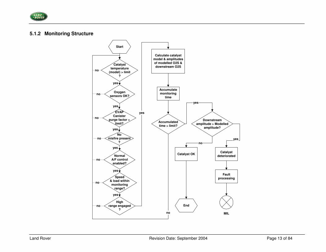
5.1.2 Monitoring Structure
yes
no
Calculate catalystmodel & amplitudesof modelled O2S &downstream O2S
Catalysttemperature
(model) > limit?
Start
EndHigh
range engaged?
Speed& load withinmonitoring
range?
NormalA/F controlenabled?
Nomisfire present
?
EVAPCanister
purge factor <limit?
Oxygensensors OK?
Accumulatemonitoring
time
Accumulatedtime > limit?
Catalyst OK
Downstreamamplitude > Modelled
amplitude?
Faultprocessing
Catalystdeteriorated
yes
yes
yes
yes
yes
yes
yes
MIL
yes
no
no
no
no
no
no
no
no

Land Rover Revision Date: September 2004 Page 14 of 84
Monitoring Cycle Computation of the Downstream Oxygen Sensor Signal Amplitudes The first step is the calculation of the amplitude of the signal oscillations of the oxygen sensor downstream of the catalyst. This is accomplished by extracting the oscillating signal component, computing the absolute value and averaging over time. Modelling of a Borderline Catalyst and the Downstream Oxygen Sensor Signal Amplitudes The model simulates the oxygen storage capability of a borderline catalyst. The signal of the downstream oxygen sensor is simulated in the catalyst model; this is based on real-time engine operating data (air fuel ratio and airflow rate). The amplitude of the modelled signal oscillations is then calculated. Signal Evaluation The signal amplitude of the downstream sensors is compared with the model over a given time. If these signal amplitudes exceed the modelled amplitudes, then the oxygen storage capability of the catalyst is less than that of a borderline catalyst. Fault Processing If the test result for the catalyst in the vehicle shows a lower oxygen storage capability than the model, then a fault is detected and an internal flag will be set. If the fault is detected again during the next drive cycle, then the MIL will be illuminated and a diagnostic trouble code (DTC) stored. Since the monitored engine has a catalyst for each of two cylinder banks, two evaluations are made with differing fault thresholds, one test is for deterioration in one of the catalysts and the second is at a reduced threshold to check for deterioration in both catalysts. Function Enable Criteria The monitoring principle is based on the detection of relevant oscillations of the downstream oxygen sensor signal during regular lambda control. It is necessary to check the driving conditions to ensure that regular lambda control is possible, e.g. fuel cut-off not present. During these conditions and for a certain time afterwards, the computation of the amplitude values and their post-processing is suspended, so that a distortion of the monitoring information is avoided.
Land Rover Revision Date: September 2004 Page 15 of 84
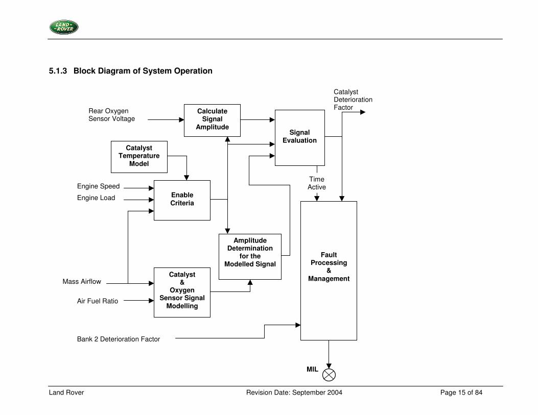
5.1.3 Block Diagram of System Operation
Calculate Signal
Amplitude
Enable Criteria
Amplitude Determination
for the Modelled Signal
Catalyst &
Oxygen Sensor Signal
Modelling
Fault Processing
& Management
Signal Evaluation
Catalyst Temperature
Model
Bank 2 Deterioration Factor
Catalyst Deterioration Factor
MIL
Rear Oxygen Sensor Voltage
Engine Speed
Engine Load
Mass Airflow
Air Fuel Ratio
Time Active
Land Rover Revision Date: September 2004 Page 16 of 84
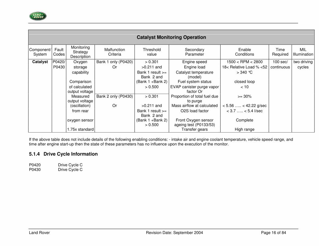
Catalyst Monitoring Operation
Component/ System
Fault Codes
Monitoring Strategy
Description
Malfunction Criteria
Threshold value
Secondary Parameter
Enable Conditions
Time Required
MIL Illumination
Catalyst P0420/ Oxygen Bank 1 only (P0420) > 0.301 Engine speed 1500 < RPM < 2800 100 sec/ two driving P0430 storage Or >0.211 and Engine load 18< Relative Load % <52 continuous cycles capability Bank 1 result >=
Bank 2 and Catalyst temperature
(model) > 340 °C
Comparison (Bank 1 +Bank 2) Fuel system status closed loop of calculated
output voltage > 0.500 EVAP canister purge vapor
factor Or < 10
Measured output voltage
Bank 2 only (P0430) > 0.301 Proportion of total fuel due to purge
>= 30%
(oscillation) Or >0.211 and Mass airflow at calculated < 5.56 ….. < 42.22 g/sec from rear Bank 1 result >=
Bank 2 and O2S load factor < 3.7 ….. < 5.4 l/sec
oxygen sensor (Bank 1 +Bank 2) > 0.500
Front Oxygen sensor ageing test (P0133/53)
Complete
1.75x standard Transfer gears High range If the above table does not include details of the following enabling conditions: - intake air and engine coolant temperature, vehicle speed range, and time after engine start-up then the state of these parameters has no influence upon the execution of the monitor.
5.1.4 Drive Cycle Information P0420 Drive Cycle C P0430 Drive Cycle C
Land Rover Revision Date: September 2004 Page 17 of 84
5.2 Misfire Monitoring
5.2.1 Description The method of engine misfire detection is based on evaluating the engine speed fluctuations. In order to detect misfiring at any cylinder the torque of each cylinder is evaluated by metering the time between two ignition events, which is a measure for the mean value of the speed of this angular segment. This means, a change of the engine torque results in a change of the engine speed. Additionally the influence of the load torque will be determined. This means the influences of different road surfaces, e.g. pavement, pot holes etc. If the mean engine speed is to be measured, influences caused by road surfaces have to be eliminated. This method consists of the following main parts:
• data acquisition, adaptation of sensor wheel is included
• calculation of engine roughness
• comparison with a threshold depending on operating points
• some extreme conditions, during which misfire detections should be disabled for a short time
• fault processing, counting procedure of single misfire events
Land Rover Revision Date: September 2004 Page 18 of 84
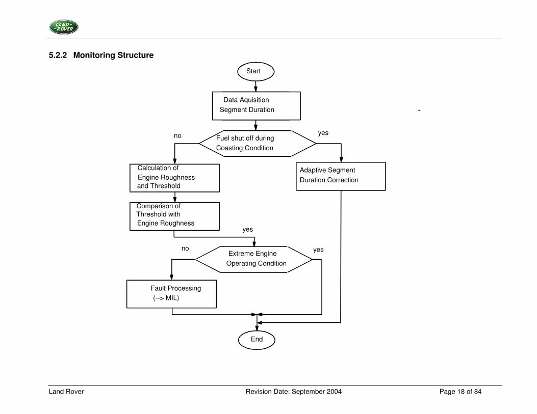
5.2.2 Monitoring Structure
Start
no yes Fuel shut off during Coasting Condition
Adaptive Segment Duration Correction
no yes
yes
End
Fault Processing (--> MIL)
Extreme Engine Operating Condition
Data Aquisition Segment Duration
Comparison of Threshold with Engine Roughness
Calculation of Engine Roughness
and Threshold
Land Rover Revision Date: September 2004 Page 19 of 84
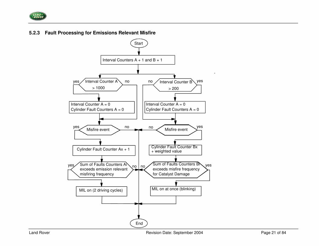
Monitoring Cycle Data acquisition The duration of the crankshaft segments is measured continuously for every combustion cycle. Sensor wheel adaptation Within a defined engine speed range and during fuel cut-off, the adaptation of the sensor wheel tolerances, instead of misfire detection, is carried out. With progressing adaptation the sensitivity of the misfire detection is increasing. The adaptation values are stored in a non-volatile memory and are taken into consideration for the calculation of the engine roughness. Misfire detection The following operating steps are performed for each measured segment corrected by the sensor wheel adaptation. Calculation of the engine roughness The engine roughness is derived from the differences of the segment durations. Different statistical methods are used to distinguish between normal changes of the segment duration and the changes due to misfiring. Detecting of multiple misfiring If several cylinders are misfiring (e.g. alternating one combustion/one misfire event) the calculated engine roughness values may be so low, that the threshold is not exceeded during misfiring and therefore misfiring would not be detected. Based on this fact, the periodicity of the engine roughness value is used as additional information during multiple misfiring. The engine roughness value is filtered and a new multiple filter value is created. If this filter value increases due to multiple misfiring, the roughness threshold is decreased. By applying this strategy, multiple misfiring is detected reliably. Calculation of the engine roughness threshold value The engine roughness threshold value consists of the base value, which is determined by a load/speed dependent map. During warm-up an engine coolant temperature dependent correction value is added. In case of multiple misfiring the threshold is reduced by an adjustable factor. Without sufficient sensor wheel adaptation the engine roughness threshold is limited to a speed dependent minimum value. A change of the threshold towards a smaller value is limited by a variation constant. Determination of misfiring Misfire detection is performed by comparing the engine roughness threshold value with the engine roughness value. If a misfire event is detected in a cylinder, the misfire detection of the next cylinder in firing order is deactivated to prevent a faulty diagnosis. Statistics, fault processing Within an interval of 1000 crankshaft revolutions the detected misfiring events are added for each cylinder. If the sum of all cylinder misfire incidents exceeds a predetermined value, the fault code for emission relevant misfiring is preliminarily stored. If only one cylinder is misfiring, a cylinder selective fault code is stored. If more than one cylinder is misfiring, the fault code for multiple misfiring is also stored. Within an interval of 200 crankshaft revolutions the detected number of misfiring events is weighted and calculated for each cylinder. The weighting factor is determined by a load/speed dependent map. If the sum of cylinder misfire incidents exceeds a predetermined value, the fault code for indicating catalyst damage relevant misfiring is stored and the MIL is illuminated at once (blinking).
Land Rover Revision Date: September 2004 Page 20 of 84
If the cylinder selective count exceeds the predetermined threshold, the following measures take place:
• the oxygen sensor closed loop system is switched to open loop • the cylinder selective fault code is stored. If more than one cylinder is misfiring, the fault code for multiple misfire is also stored • the fuel supply to the respective cylinder is cut-off
All misfire counters are reset after each interval.
Land Rover Revision Date: September 2004 Page 21 of 84
5.2.3 Fault Processing for Emissions Relevant Misfire
Start
no yes
End
Interval Counters A + 1 and B + 1
Interval Counter A
> 1000 Interval Counter B > 200
Interval Counter A = 0 Cylinder Fault Counters A = 0
Interval Counter A = 0 Cylinder Fault Counters A = 0
Misfire event Misfire event
Cylinder Fault Counter Ax + 1 Cylinder Fault Counter Bx + weighted value
Sum of Faults Counters Bi exceeds misfire frequency
for Catalyst Damage
MIL on (2 driving cycles) MIL on at once (blinking)
no yes
no no yes yes
yes no
Sum of Faults Counters Ai exceeds emission relevant
misfiring frequency
no yes
Land Rover Revision Date: September 2004 Page 22 of 84
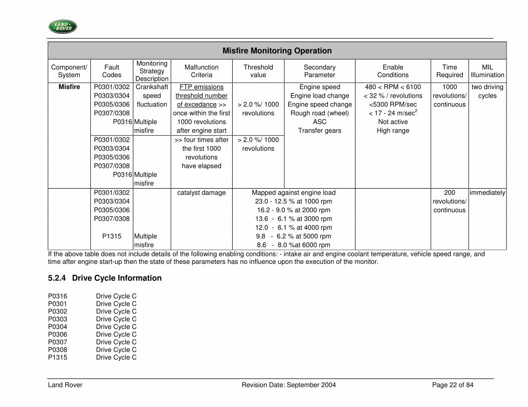
Misfire Monitoring Operation
Component/ System
Fault Codes
Monitoring Strategy
Description
Malfunction Criteria
Threshold value
Secondary Parameter
Enable Conditions
Time Required
MIL Illumination
P0301/0302 Crankshaft FTP emissions Engine speed 480 < RPM < 6100 1000 two driving P0303/0304 speed threshold number Engine load change < 32 % / revolutions revolutions/ cycles P0305/0306 fluctuation of excedance >> > 2.0 %/ 1000 Engine speed change <5300 RPM/sec continuous P0307/0308 once within the first revolutions Rough road (wheel) < 17 - 24 m/sec2
P0316 Multiple 1000 revolutions ASC Not active misfire after engine start Transfer gears High range
P0301/0302 >> four times after > 2.0 %/ 1000 P0303/0304 the first 1000 revolutions P0305/0306 revolutions P0307/0308 have elapsed
P0316 Multiple
Misfire
misfire P0301/0302 catalyst damage Mapped against engine load 200 immediately
P0303/0304 23.0 - 12.5 % at 1000 rpm revolutions/ P0305/0306 16.2 - 9.0 % at 2000 rpm continuous P0307/0308 13.6 - 6.1 % at 3000 rpm
12.0 - 6.1 % at 4000 rpm P1315 Multiple 9.8 - 6.2 % at 5000 rpm
misfire 8.6 - 8.0 %at 6000 rpm If the above table does not include details of the following enabling conditions: - intake air and engine coolant temperature, vehicle speed range, and time after engine start-up then the state of these parameters has no influence upon the execution of the monitor.
5.2.4 Drive Cycle Information P0316 Drive Cycle C P0301 Drive Cycle C P0302 Drive Cycle C P0303 Drive Cycle C P0304 Drive Cycle C P0306 Drive Cycle C P0307 Drive Cycle C P0308 Drive Cycle C P1315 Drive Cycle C
Land Rover Revision Date: September 2004 Page 23 of 84
5.3 Secondary Air Injection System Monitoring
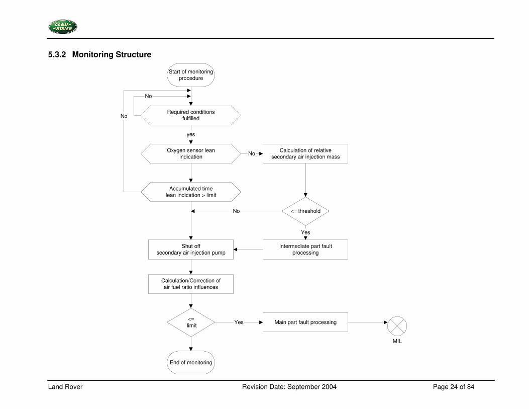
5.3.1 Description At cold start the secondary air injection pump and valve are switched on for their normal operating function. The secondary air delivered into the exhaust gas causes a lean mixture indicated by the output voltage of the front oxygen sensor. Any time the oxygen sensor indicates a rich mixture (voltage > a fixed limit) within a predetermined time range and the calculation of the relative secondary air mass is < a defined threshold, the secondary air injection system appears to be faulty. A correction procedure follows immediately after the secondary air injection system is switched off. The air fuel ratio influence is determined by the deviation of the lambda-controller. If influence < a fixed threshold, finally a fault will be detected. If influence > a fixed threshold the results of the diagnosis will be rejected As long as a lean mixture (voltage < a fixed limit) is indicated from the front oxygen sensor within a predetermined time range and the correction of air fuel ratio influence (after secondary air injection pump shuts-off) is < a fixed threshold a fault will also be detected.
Land Rover Revision Date: September 2004 Page 24 of 84
5.3.2 Monitoring Structure
Start of monitoringprocedure
Required conditionsfulfilled
Oxygen sensor leanindication
Accumulated timelean indication > limit
Shut offsecondary air injection pump
Calculation/Correction ofair fuel ratio influences
<= threshold
End of monitoring
Calculation of relativesecondary air injection mass
<= limit
Intermediate part faultprocessing
Main part fault processing
MIL
yes
No
No
No
Yes
No
Yes
Land Rover Revision Date: September 2004 Page 25 of 84
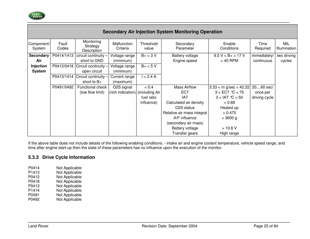
Secondary Air Injection System Monitoring Operation
Component/ System
Fault Codes
Monitoring Strategy
Description
Malfunction Criteria
Threshold value
Secondary Parameter
Enable Conditions
Time Required
MIL Illumination
Secondary P0414/1413 circuit continuity – Voltage range B+ < 3 V Battery voltage 9.5 V < B+ < 17 V immediately/ two driving Air short to GND (minimum) Engine speed > 40 RPM continuous cycles
Injection P0412/0418 Circuit continuity – Voltage range B+ < 5 V System open circuit (minimum)
P0413/1414 Circuit continuity – Current range I > 2.4 A short to B+ (maximum) P0491/0492 Functional check O2S signal < 0.4 Mass Airflow 3.33 < m g/sec < 42.22 20....60 sec/ (low flow limit) (rich indication) (including Air ECT 3 < ECT °C < 75 once per fuel ratio IAT 3 < IAT °C < 50 driving cycle influence) Calculated air density > 0.68 O2S status Heated up Relative air mass integral > 0.475 A/F influence < 3600 g (secondary air mass) Battery voltage > 10.8 V Transfer gears High range
If the above table does not include details of the following enabling conditions: - intake air and engine coolant temperature, vehicle speed range, and time after engine start-up then the state of these parameters has no influence upon the execution of the monitor.
5.3.3 Drive Cycle Information P0414 Not Applicable P1413 Not Applicable P0412 Not Applicable P0418 Not Applicable P0413 Not Applicable P1414 Not Applicable P0491 Not Applicable P0492 Not Applicable
Land Rover Revision Date: September 2004 Page 26 of 84
5.4 Evaporative Emission System Leak Measurement
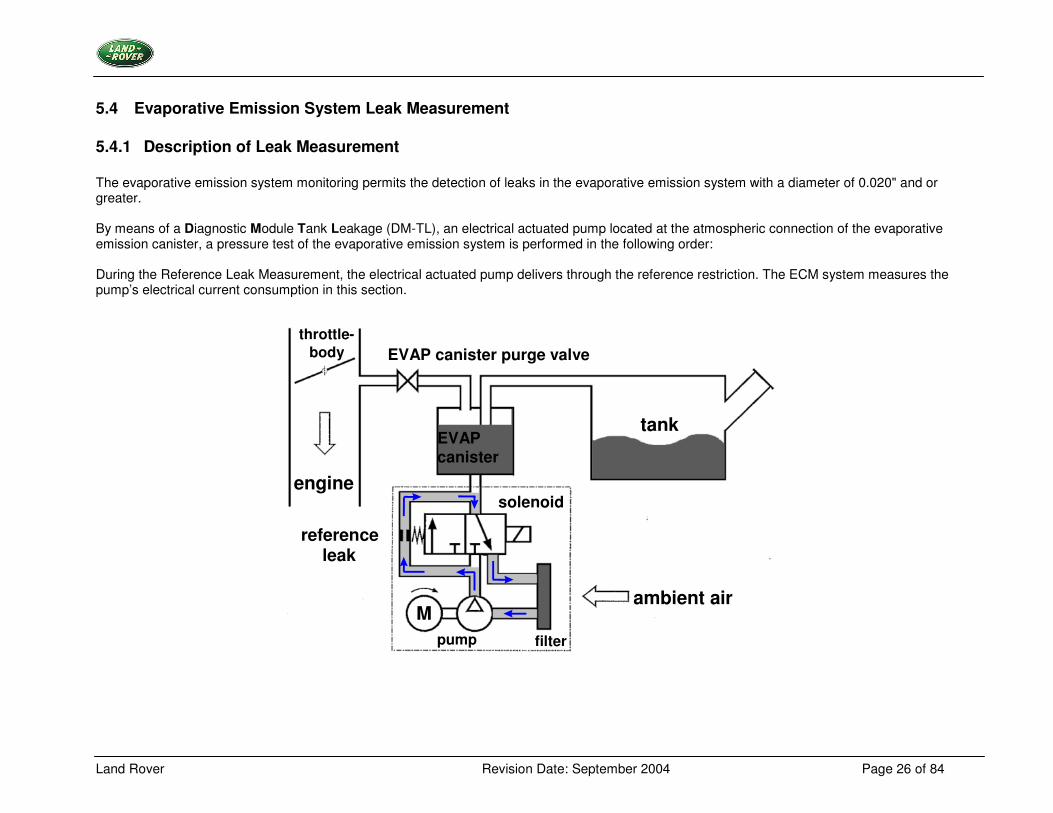
5.4.1 Description of Leak Measurement The evaporative emission system monitoring permits the detection of leaks in the evaporative emission system with a diameter of 0.020" and or greater. By means of a Diagnostic Module Tank Leakage (DM-TL), an electrical actuated pump located at the atmospheric connection of the evaporative emission canister, a pressure test of the evaporative emission system is performed in the following order: During the Reference Leak Measurement, the electrical actuated pump delivers through the reference restriction. The ECM system measures the pump’s electrical current consumption in this section.
tank EVAP canister
ambient air
solenoid
filter
M
engine
throttle- body EVAP canister purge valve
reference leak
pump
Land Rover Revision Date: September 2004 Page 27 of 84
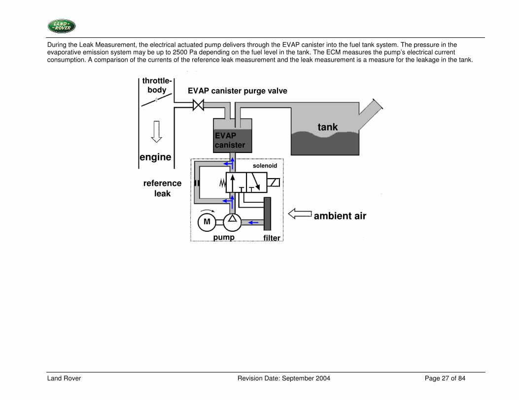
During the Leak Measurement, the electrical actuated pump delivers through the EVAP canister into the fuel tank system. The pressure in the evaporative emission system may be up to 2500 Pa depending on the fuel level in the tank. The ECM measures the pump’s electrical current consumption. A comparison of the currents of the reference leak measurement and the leak measurement is a measure for the leakage in the tank.
tank EVAP canister
ambient air
solenoid
filter
engine
throttle- body EVAP canister purge valve
reference leak
pump
Land Rover Revision Date: September 2004 Page 28 of 84
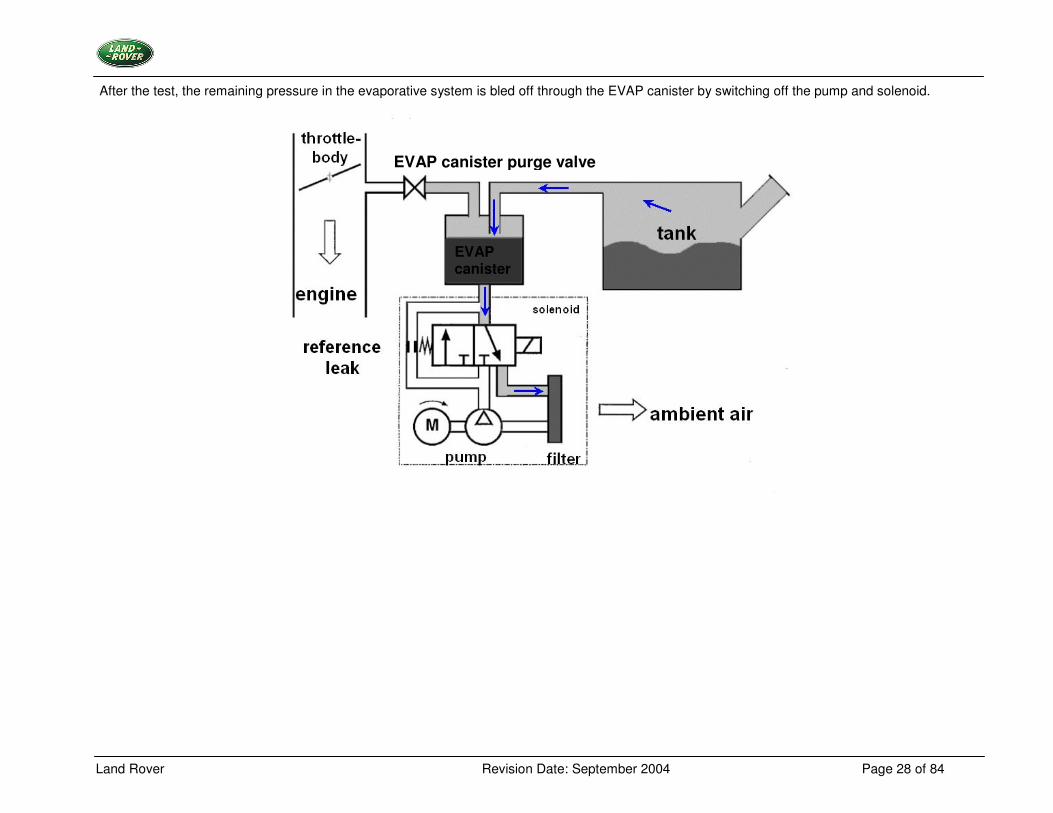
After the test, the remaining pressure in the evaporative system is bled off through the EVAP canister by switching off the pump and solenoid.
EVAP canister purge valve
EVAP canister
Land Rover Revision Date: September 2004 Page 29 of 84
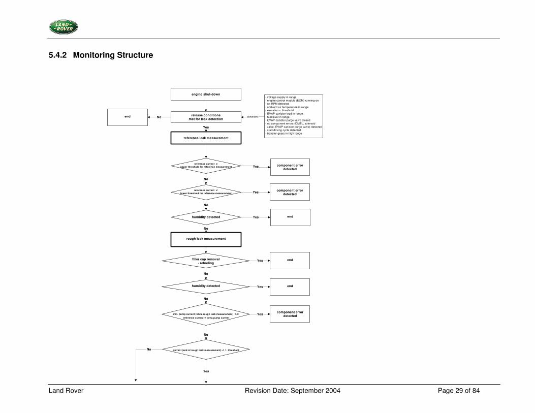
5.4.2 Monitoring Structure
current (end of rough leak measurement) < 1. threshold
reference leak measurement
rough leak measurement
No
engine shut-down
release conditionsmet for leak detection
conditions
component errordetected
Yes
Yes
min. pump current (while rough leak measurement) >= reference current + delta pump current
Yes
humidity detected Yes
component errordetected
end
reference current >upper threshold for reference measurement
No
- voltage supply in range- engine control module (ECM) running-on- no RPM detected- ambient air temperature in range- elevation < threshold- EVAP canister load in range- fuel level in range- EVAP canister purge valve closed- no component errors (DMTL, solenoid valve, EVAP canister purge valve) detected- start driving cycle detected- transfer gears in high range
Yes
No
No
component errordetectedYes
reference current <lower threshold for reference measurement
No
end
filler cap removal- refueling
end
No
Yes
humidity detected endYes
No
No
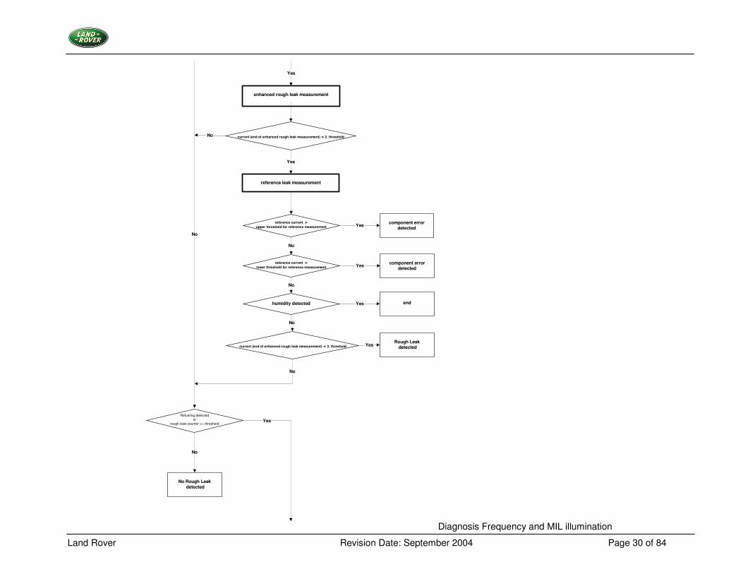
Land Rover Revision Date: September 2004 Page 30 of 84
reference leak measurement
component errordetectedYes
humidity detected Yes end
reference current >upper threshold for reference measurement
No
No
component errordetectedYes
reference current <lower threshold for reference measurement
No
Rough Leak detectedYes
No
current (end of enhanced rough leak measurement) < 2. threshold
No
enhanced rough leak measurement
current (end of enhanced rough leak measurement) < 2. thresholdNo
Yes
Yes
Refueling detectedor
rough leak counter >= threshold
No
No Rough Leak detected
Yes
Diagnosis Frequency and MIL illumination
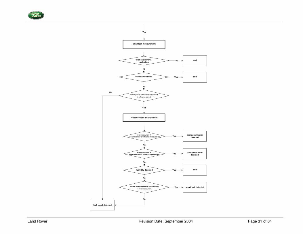
Land Rover Revision Date: September 2004 Page 31 of 84
leak proof detected
Yes
current (end of small leak measurement)< reference current
small leak measurement
filler cap removal- refueling
endYes
No
Yes
humidity detected
No
endYes
No
reference leak measurement
component errordetectedYes
humidity detected Yes end
reference current >upper threshold for reference measurement
No
No
component errordetectedYes
reference current <lower threshold for reference measurement
No
Yes current (end of small leak measurement)
< reference current
No
small leak detected
Land Rover Revision Date: September 2004 Page 32 of 84
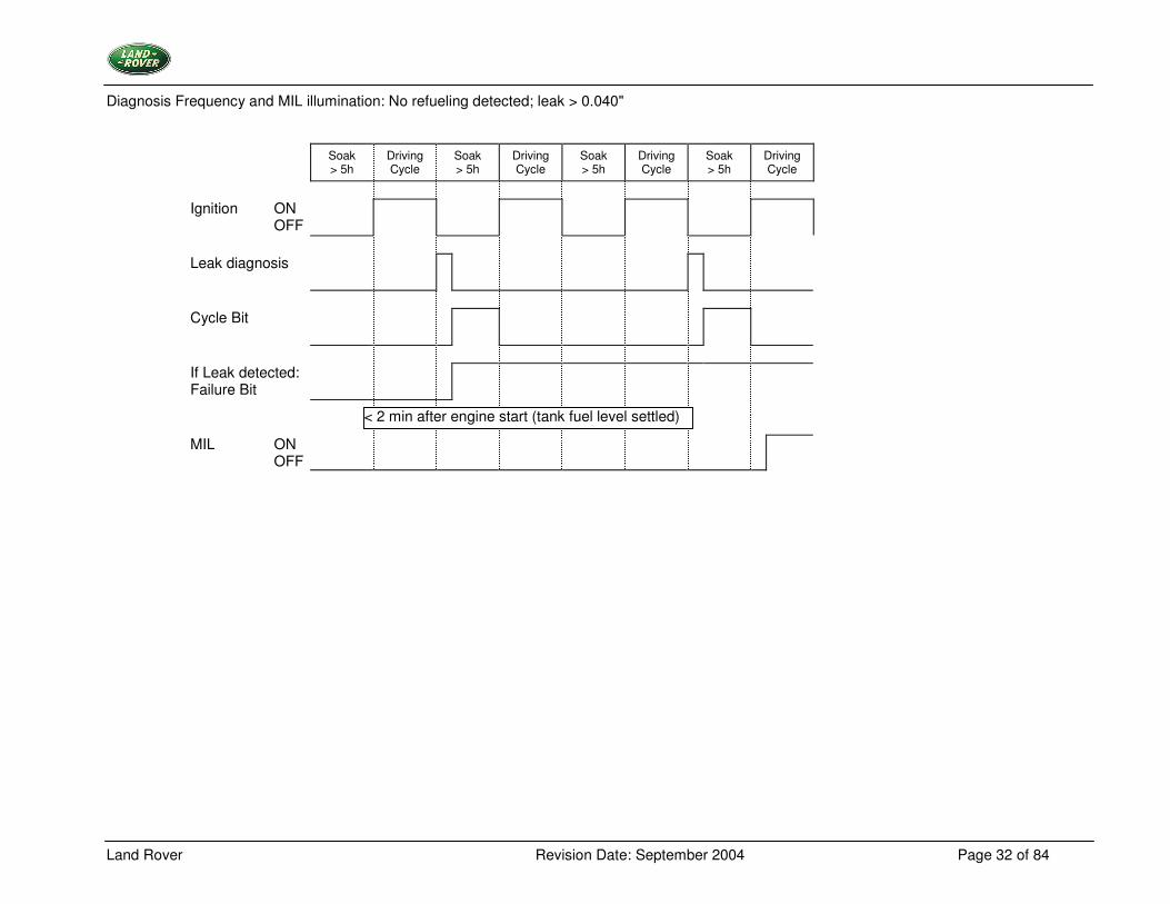
Diagnosis Frequency and MIL illumination: No refueling detected; leak > 0.040"
Soak > 5h
Driving Cycle
Soak > 5h
Driving Cycle
Soak > 5h
Driving Cycle
Soak > 5h
Driving Cycle
Ignition ON OFF
Leak diagnosis
Cycle Bit
If Leak detected: Failure Bit
MIL ON OFF
< 2 min after engine start (tank fuel level settled)
Land Rover Revision Date: September 2004 Page 33 of 84
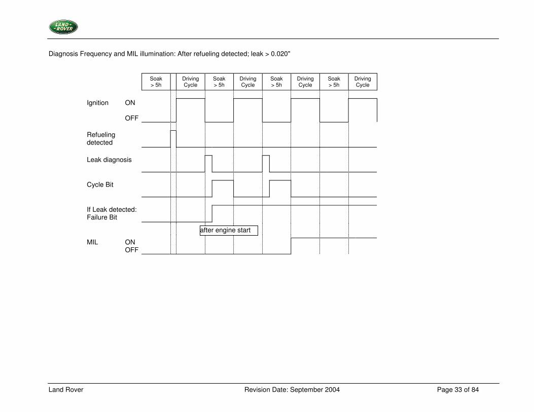
Diagnosis Frequency and MIL illumination: After refueling detected; leak > 0.020"
Soak > 5h
Driving Cycle
Soak > 5h
Driving Cycle
Soak > 5h
Driving Cycle
Soak > 5h
Driving Cycle
Ignition ON OFF
Refueling detected
Leak diagnosis
Cycle Bit
If Leak detected: Failure Bit
MIL ON OFF
after engine start
Land Rover Revision Date: September 2004 Page 34 of 84
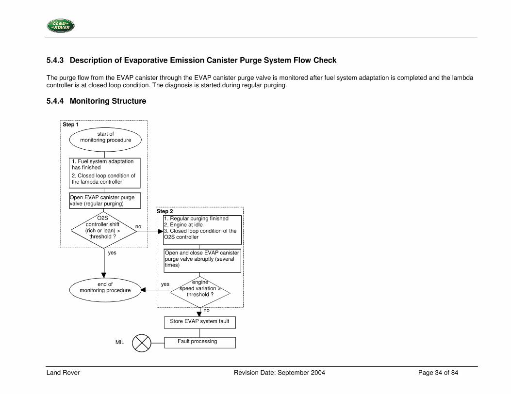
5.4.3 Description of Evaporative Emission Canister Purge System Flow Check The purge flow from the EVAP canister through the EVAP canister purge valve is monitored after fuel system adaptation is completed and the lambda controller is at closed loop condition. The diagnosis is started during regular purging.
5.4.4 Monitoring Structure
start of monitoring procedure
2. Closed loop condition of the lambda controller
Open EVAP canister purge valve (regular purging)
O2S controller shift (rich or lean) >
threshold ?
yes
end of monitoring procedure
yes
no
no
engine speed variation >
threshold ?
Fault processing MIL
Step 2
Step 1
1. Regular purging finished 2. Engine at idle 3. Closed loop condition of the O2S controller
1. Fuel system adaptation has finished
Open and close EVAP canister purge valve abruptly (several times)
Store EVAP system fault
Land Rover Revision Date: September 2004 Page 35 of 84
Monitoring Cycle of Evaporative Emission Canister Purge System Flow Check Step 1 - For rich or lean mixture Flow through the EVAP canister purge valve is assumed as soon as the lambda controller is compensating for a rich or a lean shift. After this procedure the diagnosis is completed and the EVAP canister purge system resumes working normally. Step 2 - For a stoichiometric mixture In this case the lambda controller does not need to compensate for a deviation. Therefore, after finishing the regular purging, the EVAP canister purge valve is opened and closed abruptly several times. The effect of additional cylinder charge will trigger a variation of the engine idle speed. A predetermined value is reached if the system functions properly and the diagnosis procedure is completed. To start the diagnosis function (step 2) several conditions have to be satisfied.
• vehicle speed = 0 • engine at idle speed • closed loop of lambda controller • engine coolant temperature > fixed limit • transfer gears in high range
Furthermore if the diagnosis has already been started and one of the conditions has not been satisfied continuously, the process will be interrupted and started again later.
• engine idle speed variation < fixed limit
Land Rover Revision Date: September 2004 Page 36 of 84
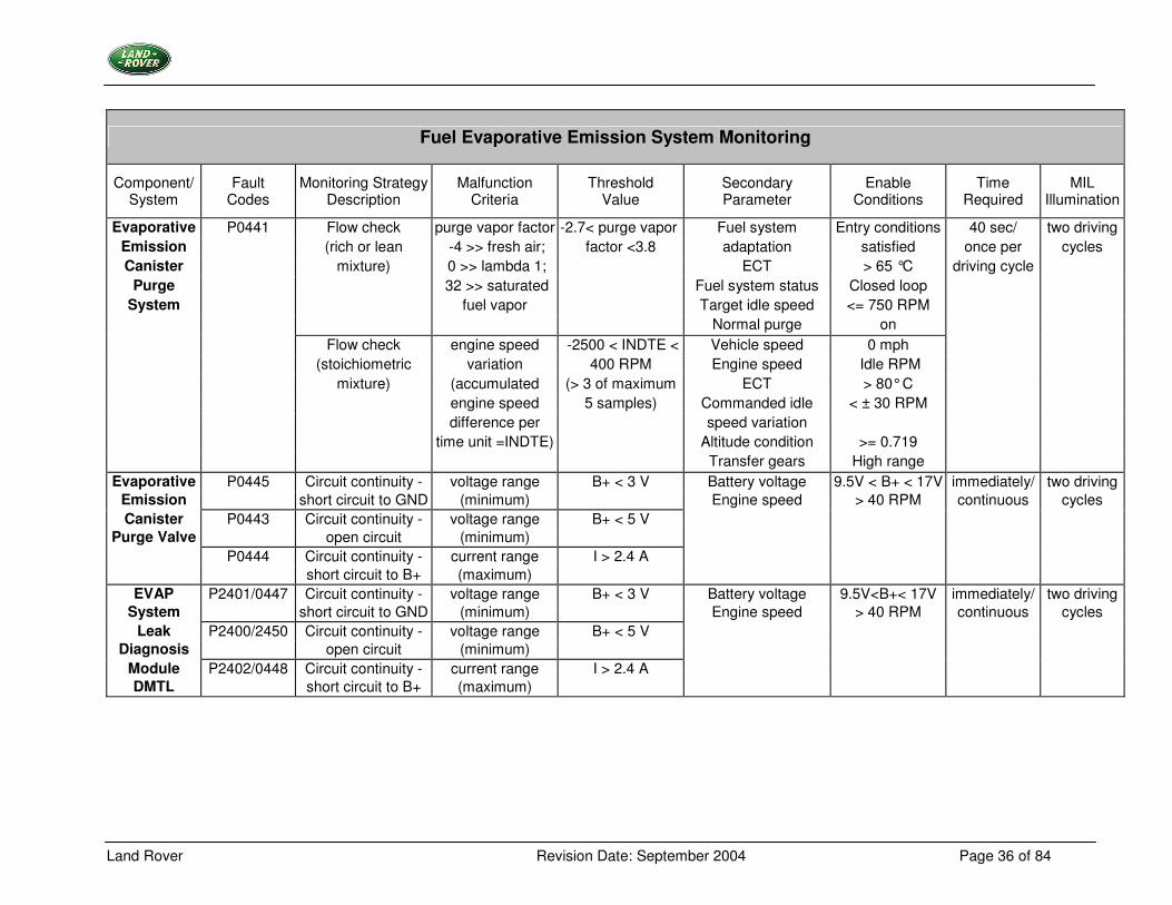
Fuel Evaporative Emission System Monitoring
Component/ System
Fault Codes
Monitoring Strategy Description
Malfunction Criteria
Threshold Value
Secondary Parameter
Enable Conditions
Time Required
MIL Illumination
Evaporative P0441 Flow check purge vapor factor -2.7< purge vapor Fuel system Entry conditions 40 sec/ two driving Emission (rich or lean -4 >> fresh air; factor <3.8 adaptation satisfied once per cycles Canister mixture) 0 >> lambda 1; ECT > 65 °C driving cycle
Purge 32 >> saturated Fuel system status Closed loop System fuel vapor Target idle speed <= 750 RPM
Normal purge on Flow check engine speed -2500 < INDTE < Vehicle speed 0 mph (stoichiometric variation 400 RPM Engine speed Idle RPM
mixture) (accumulated (> 3 of maximum ECT > 80° C engine speed 5 samples) Commanded idle < ± 30 RPM difference per speed variation time unit =INDTE) Altitude condition >= 0.719 Transfer gears High range
Evaporative P0445 Circuit continuity - voltage range B+ < 3 V Battery voltage 9.5V < B+ < 17V immediately/ two driving Emission short circuit to GND (minimum) Engine speed > 40 RPM continuous cycles Canister P0443 Circuit continuity - voltage range B+ < 5 V
Purge Valve open circuit (minimum) P0444 Circuit continuity - current range I > 2.4 A short circuit to B+ (maximum)
EVAP P2401/0447 Circuit continuity - voltage range B+ < 3 V Battery voltage 9.5V<B+< 17V immediately/ two driving System short circuit to GND (minimum) Engine speed > 40 RPM continuous cycles
Leak P2400/2450 Circuit continuity - voltage range B+ < 5 V Diagnosis open circuit (minimum)
Module P2402/0448 Circuit continuity - current range I > 2.4 A DMTL short circuit to B+ (maximum)
Land Rover Revision Date: September 2004 Page 37 of 84
Fuel Evaporative Emission System Monitoring
Component/ System
Fault Codes
Monitoring Strategy Description
Malfunction Criteria
Threshold Value
Secondary Parameter
Enable Conditions
Time Required
MIL Illumination
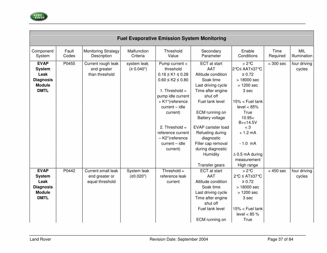
EVAP P0455 Current rough leak system leak � Pump current < ECT at start > 2°C < 300 sec four driving System end greater (� 0.040") threshold AAT 2°C� AAT�37°C cycles
Leak than threshold 0.16 �� K1 � �0.28 Altitude condition � 0.72 Diagnosis 0.60 �� K2 �� 0.80 Soak time > 18000 sec
Module Last driving cycle > 1200 sec DMTL 1. Threshold = Time after engine 3 sec
pump idle current shut off + K1*(reference Fuel tank level 15% < Fuel tank current – idle level < 85% current) ECM running on True
Battery voltage 10.95< B+<14.5V
2. Threshold = EVAP canister load < 3 reference current Refueling during + 1.2 mA – K2*(reference diagnostic current – idle Filler cap removal - 1.0 mA current) during diagnostic Humidity � 0.5 mA during measurement Transfer gears High range
EVAP P0442 Current small leak System leak Threshold = ECT at start > 2°C < 450 sec four driving System end greater or (�0.020") reference leak AAT 2°C � AT�37°C cycles
Leak equal threshold current Altitude condition � 0.72 Diagnosis Soak time > 18000 sec
Module Last driving cycle > 1200 sec DMTL Time after engine 3 sec
shut off Fuel tank level 15% < Fuel tank level < 85 % ECM running on True
Land Rover Revision Date: September 2004 Page 38 of 84
Fuel Evaporative Emission System Monitoring
Component/ System
Fault Codes
Monitoring Strategy Description
Malfunction Criteria
Threshold Value
Secondary Parameter
Enable Conditions
Time Required
MIL Illumination
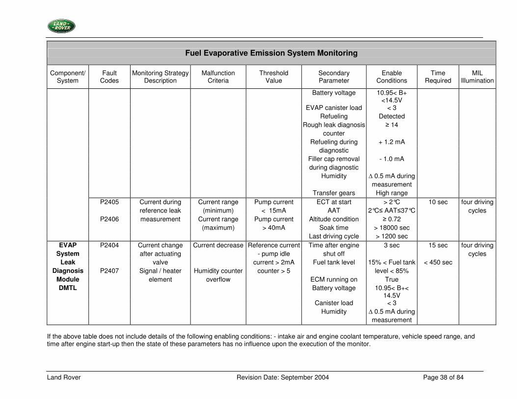
Battery voltage 10.95< B+ <14.5V
EVAP canister load < 3 Refueling Detected Rough leak diagnosis � 14 counter Refueling during + 1.2 mA diagnostic Filler cap removal - 1.0 mA during diagnostic Humidity � 0.5 mA during measurement Transfer gears High range
P2405 Current during Current range Pump current ECT at start > 2°C 10 sec four driving reference leak (minimum) < 15mA AAT 2°C� AAT�37°C cycles
P2406 measurement Current range Pump current Altitude condition � 0.72 (maximum) > 40mA Soak time > 18000 sec Last driving cycle > 1200 sec
EVAP P2404 Current change Current decrease Reference current Time after engine 3 sec 15 sec four driving System after actuating - pump idle shut off cycles
Leak valve current > 2mA Fuel tank level 15% < Fuel tank < 450 sec Diagnosis P2407 Signal / heater Humidity counter counter > 5 level < 85%
Module element overflow ECM running on True DMTL Battery voltage 10.95< B+<
14.5V
Canister load < 3 Humidity � 0.5 mA during measurement
If the above table does not include details of the following enabling conditions: - intake air and engine coolant temperature, vehicle speed range, and time after engine start-up then the state of these parameters has no influence upon the execution of the monitor.
Land Rover Revision Date: September 2004 Page 39 of 84
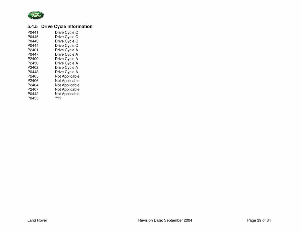
5.4.5 Drive Cycle Information P0441 Drive Cycle C P0445 Drive Cycle C P0443 Drive Cycle C P0444 Drive Cycle C P2401 Drive Cycle A P0447 Drive Cycle A P2400 Drive Cycle A P2450 Drive Cycle A P2402 Drive Cycle A P0448 Drive Cycle A P2405 Not Applicable P2406 Not Applicable P2404 Not Applicable P2407 Not Applicable P0442 Not Applicable P0455 ???
Land Rover Revision Date: September 2004 Page 40 of 84
5.5 Fuel System Monitoring
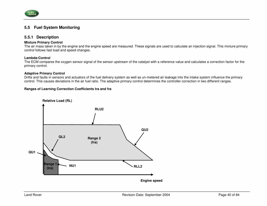
5.5.1 Description Mixture Primary Control The air mass taken in by the engine and the engine speed are measured. These signals are used to calculate an injection signal. This mixture primary control follows fast load and speed changes. Lambda-Control The ECM compares the oxygen sensor signal of the sensor upstream of the catalyst with a reference value and calculates a correction factor for the primary control. Adaptive Primary Control Drifts and faults in sensors and actuators of the fuel delivery system as well as un-metered air leakage into the intake system influence the primary control. This causes deviations in the air fuel ratio. The adaptive primary control determines the controller correction in two different ranges. Ranges of Learning Correction Coefficients tra and fra
Relative Load (RL)
Engine speed
Range 2 (fra)
QU1
NU1
QU2
RLL2
QL2
Range 1 (tra)
RLU2
Land Rover Revision Date: September 2004 Page 41 of 84
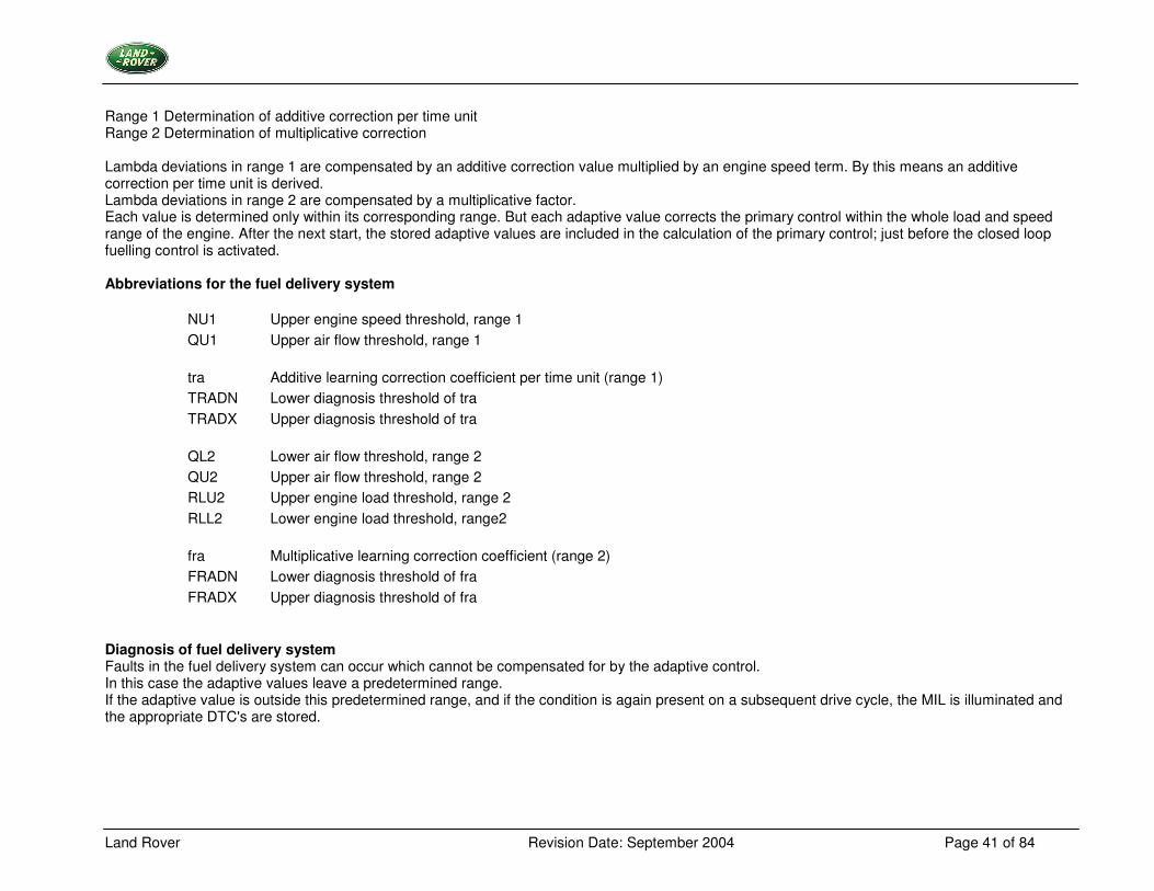
Range 1 Determination of additive correction per time unit Range 2 Determination of multiplicative correction Lambda deviations in range 1 are compensated by an additive correction value multiplied by an engine speed term. By this means an additive correction per time unit is derived. Lambda deviations in range 2 are compensated by a multiplicative factor. Each value is determined only within its corresponding range. But each adaptive value corrects the primary control within the whole load and speed range of the engine. After the next start, the stored adaptive values are included in the calculation of the primary control; just before the closed loop fuelling control is activated. Abbreviations for the fuel delivery system
NU1 Upper engine speed threshold, range 1 QU1 Upper air flow threshold, range 1
tra Additive learning correction coefficient per time unit (range 1) TRADN Lower diagnosis threshold of tra TRADX Upper diagnosis threshold of tra
QL2 Lower air flow threshold, range 2 QU2 Upper air flow threshold, range 2 RLU2 Upper engine load threshold, range 2 RLL2 Lower engine load threshold, range2
fra Multiplicative learning correction coefficient (range 2) FRADN Lower diagnosis threshold of fra FRADX Upper diagnosis threshold of fra
Diagnosis of fuel delivery system Faults in the fuel delivery system can occur which cannot be compensated for by the adaptive control. In this case the adaptive values leave a predetermined range. If the adaptive value is outside this predetermined range, and if the condition is again present on a subsequent drive cycle, the MIL is illuminated and the appropriate DTC's are stored.
Land Rover Revision Date: September 2004 Page 42 of 84
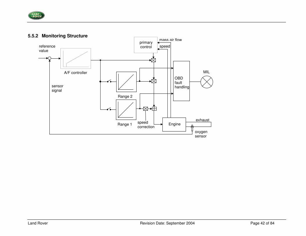
5.5.2 Monitoring Structure
A/F controller
Range 2
Range 1
reference value
sensor signal
primary control
mass air flow
speed
MIL
speed correction
Engine
oxygen sensor
OBD fault handling
exhaust
Land Rover Revision Date: September 2004 Page 43 of 84
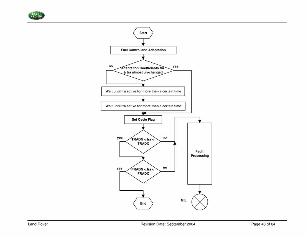
Start
Fuel Control and Adaptation
Wait until fra active for more than a certain time
Wait until tra active for more than a certain time
Set Cycle Flag
Fault Processing
Adaptation Coefficients fra & tra almost un-changed
TRADN < tra < TRADX
FRADN < fra < FRADX
End
no yes
no
noyes
yes
MIL
Land Rover Revision Date: September 2004 Page 44 of 84
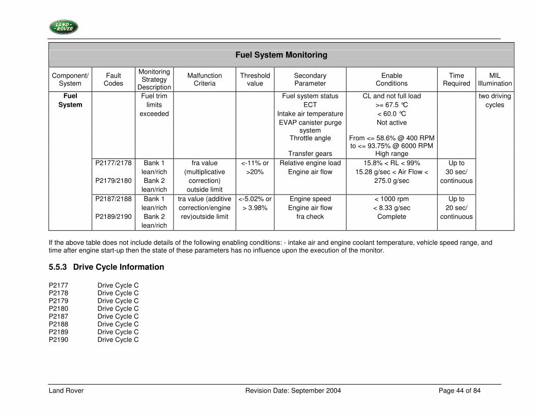
Fuel System Monitoring
Component/ System
Fault Codes
Monitoring Strategy
Description
Malfunction Criteria
Threshold value
Secondary Parameter
Enable Conditions
Time Required
MIL Illumination
Fuel Fuel trim Fuel system status CL and not full load two driving System limits ECT >= 67.5 °C cycles
exceeded Intake air temperature < 60.0 °C EVAP canister purge
system Not active
Throttle angle From <= 58.6% @ 400 RPM to <= 93.75% @ 6000 RPM
Transfer gears High range P2177/2178 Bank 1 fra value <-11% or Relative engine load 15.8% < RL < 99% Up to lean/rich (multiplicative >20% Engine air flow 15.28 g/sec < Air Flow < 30 sec/ P2179/2180 Bank 2 correction) 275.0 g/sec continuous lean/rich outside limit P2187/2188 Bank 1 tra value (additive <-5.02% or Engine speed < 1000 rpm Up to lean/rich correction/engine > 3.98% Engine air flow < 8.33 g/sec 20 sec/ P2189/2190 Bank 2 rev)outside limit fra check Complete continuous lean/rich
If the above table does not include details of the following enabling conditions: - intake air and engine coolant temperature, vehicle speed range, and time after engine start-up then the state of these parameters has no influence upon the execution of the monitor.
5.5.3 Drive Cycle Information P2177 Drive Cycle C P2178 Drive Cycle C P2179 Drive Cycle C P2180 Drive Cycle C P2187 Drive Cycle C P2188 Drive Cycle C P2189 Drive Cycle C P2190 Drive Cycle C
Land Rover Revision Date: September 2004 Page 45 of 84
5.6 Oxygen Sensor Monitoring
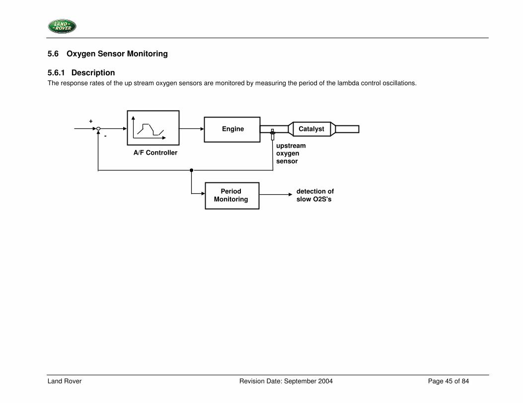
5.6.1 Description The response rates of the up stream oxygen sensors are monitored by measuring the period of the lambda control oscillations.
Engine Catalyst
upstream oxygen sensor
Period Monitoring
detection of slow O2S's
A/F Controller
+
-
Land Rover Revision Date: September 2004 Page 46 of 84
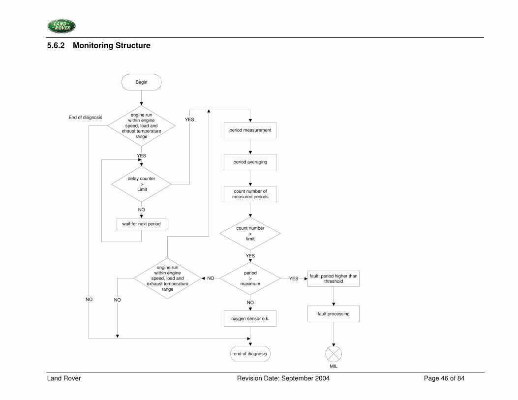
5.6.2 Monitoring Structure
Begin
engine runwithin engine
speed, load andehaust temperature
range
delay counter >
Limit
wait for next period
period measurement
period averaging
count number ofmeasured periods
count number>
limit
period>
maximum
oxygen sensor o.k.
fault: period higher thanthreshold
fault processing
MIL
end of diagnosis
YES
NO
YES
YES
NONO
End of diagnosis
engine runwithin engine
speed, load andexhaust temperature
range
NO
NO
YES
Land Rover Revision Date: September 2004 Page 47 of 84
Diagnosis Procedure of the Monitor Sensor (Downstream) The activity of the monitor sensor after reaching operating conditions is determined by two different procedures. A ) Oscillation Check (Line Crossing) If the following checks are correct, the monitor sensor will be regarded as Satisfactory:
• The monitor sensor signal (sensor voltage) is ≥ than the nominal value of the TV-Correction and voltage increases, if the λ control goes to the lean side, or
• The monitor sensor signal (sensor voltage) is < than the nominal value of the TV-Correction and voltage decreases, if the λ control goes to the rich side.
B ) Fuel Cut Off Check Additionally to the above-mentioned checks the signal behavior of the monitor sensor is checked in case of fuel cut off. Therefore the monitor sensor voltage has to be below a given nominal value in case of fuel cut off. If the monitor sensor is detected faulty by check A or B, a DTC is stored and the MIL is illuminated at the next driving cycle.
Land Rover Revision Date: September 2004 Page 48 of 84
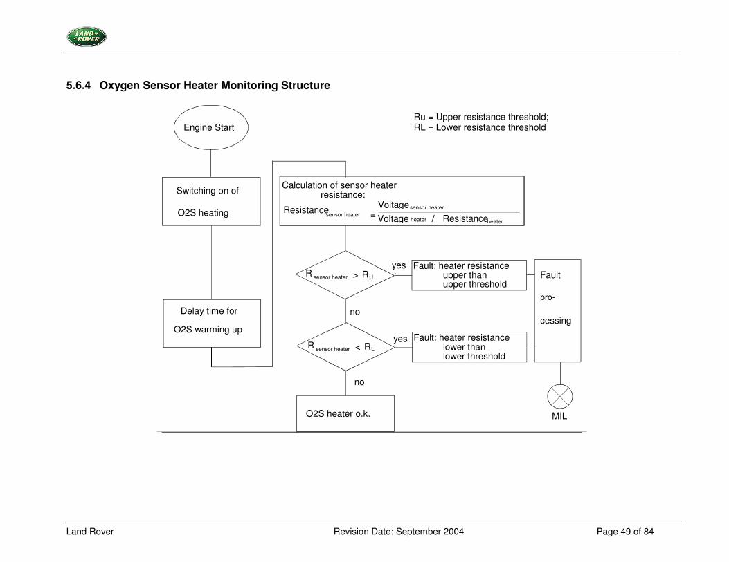
5.6.3 Oxygen Sensor Heater Monitoring Description For proper function of the oxygen sensor, the sensor element must be heated. A non-functioning heater delays the sensor readiness for closed loop control and influences emissions. The monitoring function measures both, sensor heater current (voltage drop over a shunt) and the heater voltage (heater supply voltage) to calculate the sensor heater resistance. The monitoring function is activated once per trip, if the heater has been switched on for a certain time period and the current has stabilized. Characteristics: -
• ECM controlled switching of the sensor heater.
• One shunt for each pair of O2 sensors upstream and downstream of the catalysts for current measurement.
Land Rover Revision Date: September 2004 Page 49 of 84
5.6.4 Oxygen Sensor Heater Monitoring Structure
Engine Start
Switching on of
O2S heating
Delay time for
O2S warming up
Calculation of sensor heater resistance:
Resistance Voltage Voltage / sensor heater
sensor heater
heater Resistance heater =
R sensor heater > R
R sensor heater R L
U
<
no
no
yes
yes
O2S heater o.k.
Fault: heater resistance lower than lower threshold
Fault: heater resistance upper than upper threshold
Fault
pro-
cessing
MIL
Ru = Upper resistance threshold; RL = Lower resistance threshold
Land Rover Revision Date: September 2004 Page 50 of 84
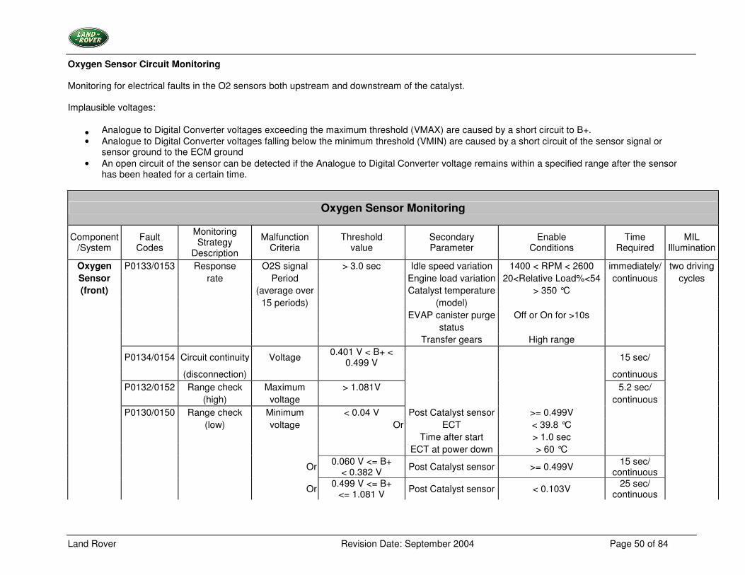
Oxygen Sensor Circuit Monitoring Monitoring for electrical faults in the O2 sensors both upstream and downstream of the catalyst. Implausible voltages:
• Analogue to Digital Converter voltages exceeding the maximum threshold (VMAX) are caused by a short circuit to B+. • Analogue to Digital Converter voltages falling below the minimum threshold (VMIN) are caused by a short circuit of the sensor signal or
sensor ground to the ECM ground • An open circuit of the sensor can be detected if the Analogue to Digital Converter voltage remains within a specified range after the sensor
has been heated for a certain time.
Oxygen Sensor Monitoring
Component /System
Fault Codes
Monitoring Strategy
Description
Malfunction Criteria
Threshold value
Secondary Parameter
Enable Conditions
Time Required
MIL Illumination
Oxygen P0133/0153 Response O2S signal > 3.0 sec Idle speed variation 1400 < RPM < 2600 immediately/ two driving Sensor rate Period Engine load variation 20<Relative Load%<54 continuous cycles (front) (average over Catalyst temperature > 350 °C
15 periods) (model) EVAP canister purge Off or On for >10s status
Transfer gears High range
P0134/0154 Circuit continuity Voltage 0.401 V < B+ < 0.499 V 15 sec/
(disconnection) continuous P0132/0152 Range check Maximum > 1.081V 5.2 sec/ (high) voltage continuous P0130/0150 Range check Minimum < 0.04 V Post Catalyst sensor >= 0.499V (low) voltage Or ECT < 39.8 °C Time after start > 1.0 sec ECT at power down > 60 °C Or 0.060 V <= B+
< 0.382 V Post Catalyst sensor >= 0.499V 15 sec/ continuous
Or 0.499 V <= B+ <= 1.081 V Post Catalyst sensor < 0.103V 25 sec/
continuous
Land Rover Revision Date: September 2004 Page 51 of 84
Oxygen Sensor Monitoring
Component /System
Fault Codes
Monitoring Strategy
Description
Malfunction Criteria
Threshold value
Secondary Parameter
Enable Conditions
Time Required
MIL Illumination
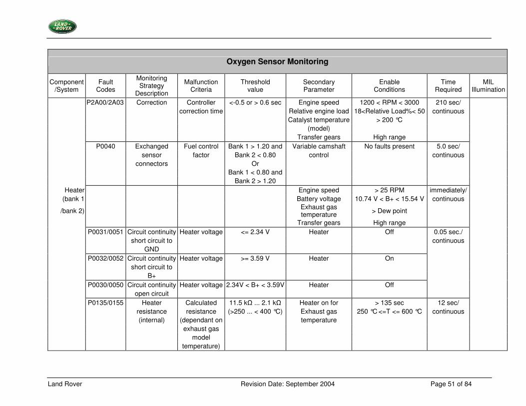
P2A00/2A03 Correction Controller <-0.5 or > 0.6 sec Engine speed 1200 < RPM < 3000 210 sec/ correction time Relative engine load 18<Relative Load%< 50 continuous Catalyst temperature > 200 °C (model) Transfer gears High range P0040 Exchanged Fuel control Bank 1 > 1.20 and Variable camshaft No faults present 5.0 sec/ sensor factor Bank 2 < 0.80 control continuous connectors Or Bank 1 < 0.80 and Bank 2 > 1.20
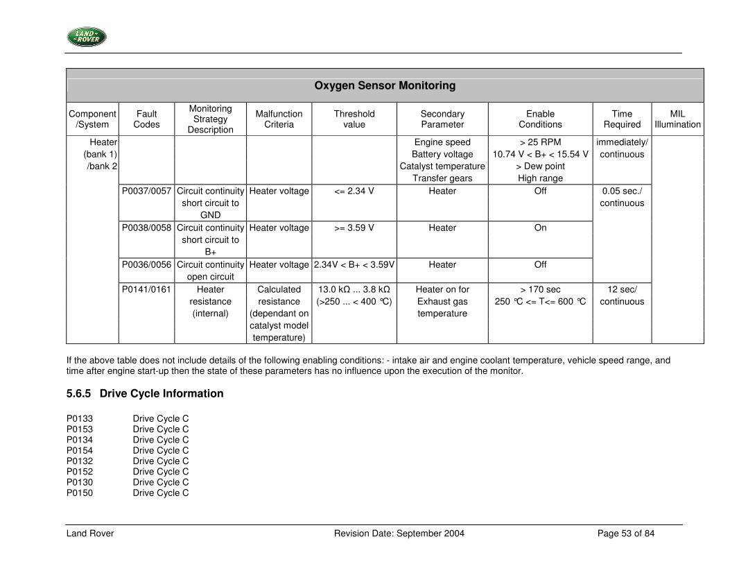
Heater Engine speed > 25 RPM immediately/ (bank 1 Battery voltage 10.74 V < B+ < 15.54 V continuous
/bank 2) Exhaust gas temperature > Dew point
Transfer gears High range P0031/0051 Circuit continuity Heater voltage <= 2.34 V Heater Off 0.05 sec./ short circuit to continuous GND
P0032/0052 Circuit continuity Heater voltage >= 3.59 V Heater On short circuit to B+ P0030/0050 Circuit continuity Heater voltage 2.34V < B+ < 3.59V Heater Off open circuit P0135/0155 Heater Calculated 11.5 k� ... 2.1 k� Heater on for > 135 sec 12 sec/ resistance resistance (>250 ... < 400 °C) Exhaust gas 250 °C <=T <= 600 °C continuous (internal) (dependant on temperature exhaust gas model temperature)
Land Rover Revision Date: September 2004 Page 52 of 84
Oxygen Sensor Monitoring
Component /System
Fault Codes
Monitoring Strategy
Description
Malfunction Criteria
Threshold value
Secondary Parameter
Enable Conditions
Time Required
MIL Illumination
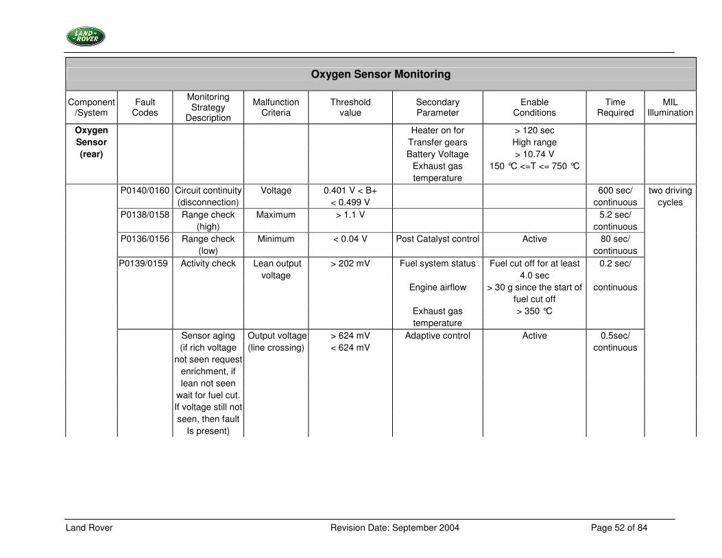
Oxygen Heater on for > 120 sec Sensor Transfer gears High range (rear) Battery Voltage > 10.74 V
Exhaust gas 150 °C <=T <= 750 °C temperature P0140/0160 Circuit continuity Voltage 0.401 V < B+ 600 sec/ two driving (disconnection) < 0.499 V continuous cycles P0138/0158 Range check Maximum > 1.1 V 5.2 sec/ (high) continuous P0136/0156 Range check Minimum < 0.04 V Post Catalyst control Active 80 sec/ (low) continuous P0139/0159 Activity check Lean output > 202 mV Fuel system status Fuel cut off for at least 0.2 sec/ voltage 4.0 sec Engine airflow > 30 g since the start of continuous fuel cut off Exhaust gas > 350 °C temperature
Sensor aging Output voltage > 624 mV Adaptive control Active 0.5sec/ (if rich voltage (line crossing) < 624 mV continuous not seen request enrichment, if lean not seen wait for fuel cut. If voltage still not seen, then fault Is present)
Land Rover Revision Date: September 2004 Page 53 of 84
Oxygen Sensor Monitoring
Component /System
Fault Codes
Monitoring Strategy
Description
Malfunction Criteria
Threshold value
Secondary Parameter
Enable Conditions
Time Required
MIL Illumination
Heater Engine speed > 25 RPM immediately/ (bank 1) Battery voltage 10.74 V < B+ < 15.54 V continuous /bank 2 Catalyst temperature > Dew point
Transfer gears High range P0037/0057 Circuit continuity Heater voltage <= 2.34 V Heater Off 0.05 sec./ short circuit to continuous GND
P0038/0058 Circuit continuity Heater voltage >= 3.59 V Heater On short circuit to B+ P0036/0056 Circuit continuity Heater voltage 2.34V < B+ < 3.59V Heater Off open circuit P0141/0161 Heater Calculated 13.0 k� ... 3.8 k� Heater on for > 170 sec 12 sec/ resistance resistance (>250 ... < 400 °C) Exhaust gas 250 °C <= T<= 600 °C continuous (internal) (dependant on temperature catalyst model temperature)
If the above table does not include details of the following enabling conditions: - intake air and engine coolant temperature, vehicle speed range, and time after engine start-up then the state of these parameters has no influence upon the execution of the monitor.
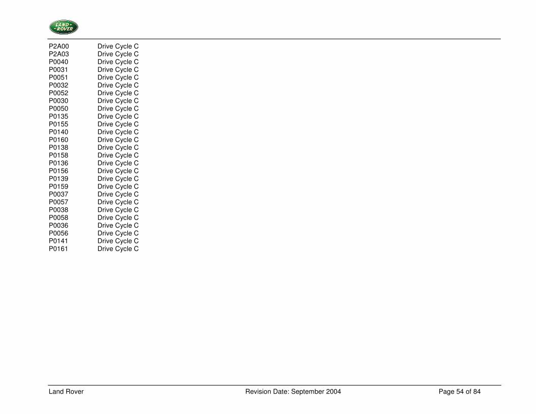
5.6.5 Drive Cycle Information P0133 Drive Cycle C P0153 Drive Cycle C P0134 Drive Cycle C P0154 Drive Cycle C P0132 Drive Cycle C P0152 Drive Cycle C P0130 Drive Cycle C P0150 Drive Cycle C
Land Rover Revision Date: September 2004 Page 54 of 84
P2A00 Drive Cycle C P2A03 Drive Cycle C P0040 Drive Cycle C P0031 Drive Cycle C P0051 Drive Cycle C P0032 Drive Cycle C P0052 Drive Cycle C P0030 Drive Cycle C P0050 Drive Cycle C P0135 Drive Cycle C P0155 Drive Cycle C P0140 Drive Cycle C P0160 Drive Cycle C P0138 Drive Cycle C P0158 Drive Cycle C P0136 Drive Cycle C P0156 Drive Cycle C P0139 Drive Cycle C P0159 Drive Cycle C P0037 Drive Cycle C P0057 Drive Cycle C P0038 Drive Cycle C P0058 Drive Cycle C P0036 Drive Cycle C P0056 Drive Cycle C P0141 Drive Cycle C P0161 Drive Cycle C
Land Rover Revision Date: September 2004 Page 55 of 84
5.7 Thermostat Monitoring
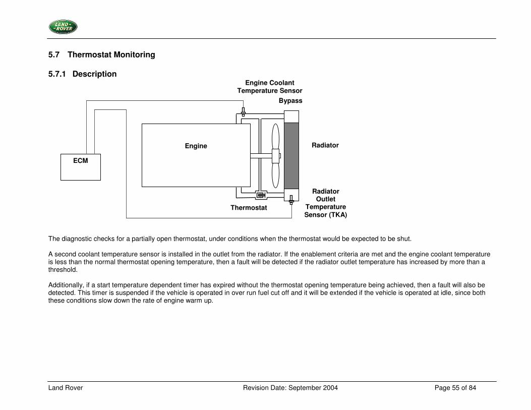
5.7.1 Description The diagnostic checks for a partially open thermostat, under conditions when the thermostat would be expected to be shut. A second coolant temperature sensor is installed in the outlet from the radiator. If the enablement criteria are met and the engine coolant temperature is less than the normal thermostat opening temperature, then a fault will be detected if the radiator outlet temperature has increased by more than a threshold.
Additionally, if a start temperature dependent timer has expired without the thermostat opening temperature being achieved, then a fault will also be detected. This timer is suspended if the vehicle is operated in over run fuel cut off and it will be extended if the vehicle is operated at idle, since both these conditions slow down the rate of engine warm up.
Engine
ECM
Radiator
Bypass
Thermostat
Engine Coolant Temperature Sensor
Radiator Outlet
Temperature Sensor (TKA)
Land Rover Revision Date: September 2004 Page 56 of 84
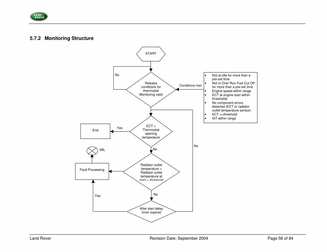
5.7.2 Monitoring Structure
START
Release conditions for
thermostat Monitoring valid
No • Not at idle for more than a pre-set time
• Not in Over Run Fuel Cut Off for more than a pre-set time
• Engine speed within range • ECT at engine start within
thresholds • No component errors
detected (ECT or radiator outlet temperature sensor)
• ECT >=threshold • IAT within range
Conditions met
ECT > Thermostat
opening temperature
End
Yes
Radiator outlet temperature > Radiator outlet temperature at
start + threshold
After start delay timer expired
No
Fault Processing
MIL
No Yes
No
Land Rover Revision Date: September 2004 Page 57 of 84
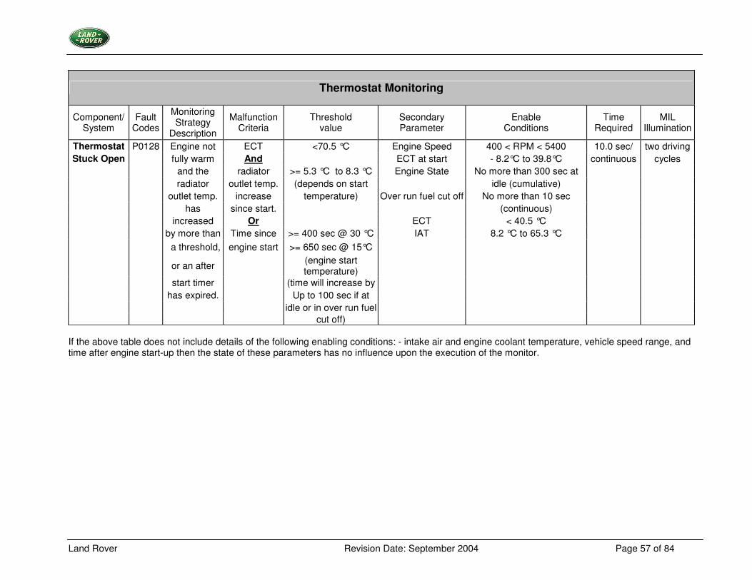
Thermostat Monitoring
Component/ System
Fault Codes
Monitoring Strategy
Description
Malfunction Criteria
Threshold value
Secondary Parameter
Enable Conditions
Time Required
MIL Illumination
Thermostat P0128 Engine not ECT <70.5 °C Engine Speed 400 < RPM < 5400 10.0 sec/ two driving Stuck Open fully warm And ECT at start - 8.2°C to 39.8°C continuous cycles
and the radiator >= 5.3 °C to 8.3 °C Engine State No more than 300 sec at radiator outlet temp. (depends on start idle (cumulative) outlet temp. increase temperature) Over run fuel cut off No more than 10 sec has since start. (continuous) increased Or ECT < 40.5 °C by more than Time since >= 400 sec @ 30 °C IAT 8.2 °C to 65.3 °C a threshold, engine start >= 650 sec @ 15°C
or an after (engine start temperature)
start timer (time will increase by has expired. Up to 100 sec if at idle or in over run fuel cut off)
If the above table does not include details of the following enabling conditions: - intake air and engine coolant temperature, vehicle speed range, and time after engine start-up then the state of these parameters has no influence upon the execution of the monitor.
Land Rover Revision Date: September 2004 Page 58 of 84
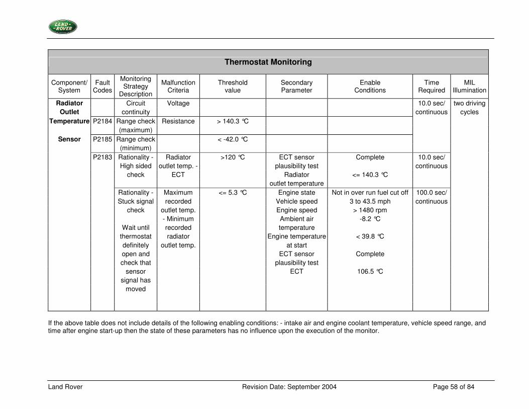
Thermostat Monitoring
Component/ System
Fault Codes
Monitoring Strategy
Description
Malfunction Criteria
Threshold value
Secondary Parameter
Enable Conditions
Time Required
MIL Illumination
Radiator Circuit Voltage 10.0 sec/ two driving Outlet continuity continuous cycles
Temperature P2184 Range check Resistance > 140.3 °C (maximum)
Sensor P2185 Range check < -42.0 °C (minimum) P2183 Rationality - Radiator >120 °C ECT sensor Complete 10.0 sec/ High sided outlet temp. - plausibility test continuous check ECT Radiator <= 140.3 °C outlet temperature Rationality - Maximum <= 5.3 °C Engine state Not in over run fuel cut off 100.0 sec/ Stuck signal recorded Vehicle speed 3 to 43.5 mph continuous check outlet temp. Engine speed > 1480 rpm - Minimum Ambient air -8.2 °C Wait until recorded temperature thermostat radiator Engine temperature < 39.8 °C definitely outlet temp. at start open and ECT sensor Complete check that plausibility test sensor ECT 106.5 °C signal has moved
If the above table does not include details of the following enabling conditions: - intake air and engine coolant temperature, vehicle speed range, and time after engine start-up then the state of these parameters has no influence upon the execution of the monitor.
Land Rover Revision Date: September 2004 Page 59 of 84
5.7.3 Drive Cycle Information P0128 Drive Cycle D P2184 Drive Cycle D P2185 Drive Cycle D P2183 Drive Cycle D
Land Rover Revision Date: September 2004 Page 60 of 84
5.8 Positive Crankcase Ventilation (PCV) System Monitoring
5.8.1 Description
���
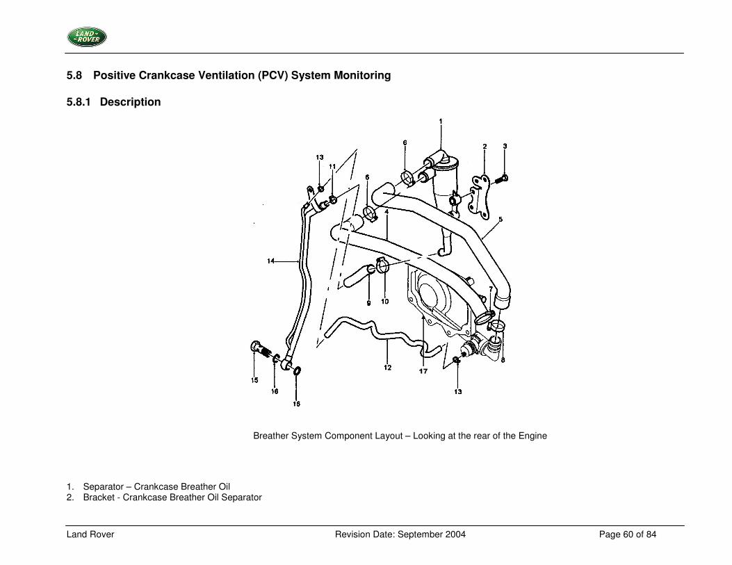
Breather System Component Layout – Looking at the rear of the Engine
1. Separator – Crankcase Breather Oil 2. Bracket - Crankcase Breather Oil Separator
Land Rover Revision Date: September 2004 Page 61 of 84
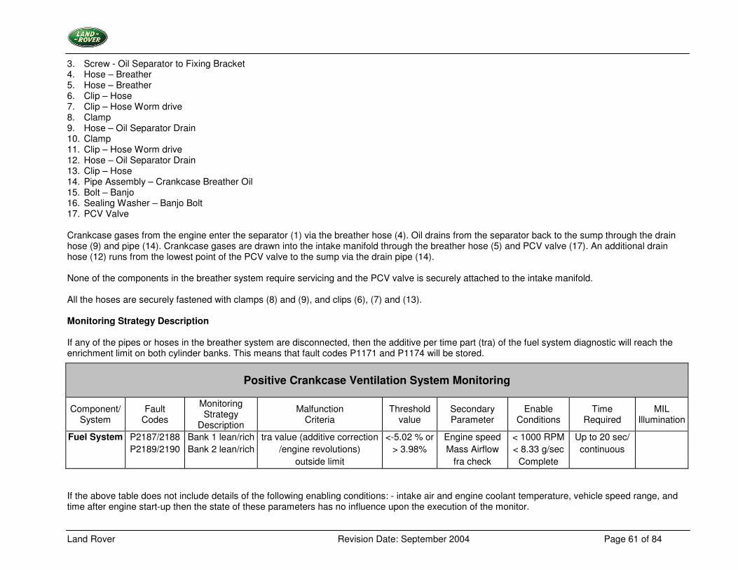
3. Screw - Oil Separator to Fixing Bracket 4. Hose – Breather 5. Hose – Breather 6. Clip – Hose 7. Clip – Hose Worm drive 8. Clamp 9. Hose – Oil Separator Drain 10. Clamp 11. Clip – Hose Worm drive 12. Hose – Oil Separator Drain 13. Clip – Hose 14. Pipe Assembly – Crankcase Breather Oil 15. Bolt – Banjo 16. Sealing Washer – Banjo Bolt 17. PCV Valve Crankcase gases from the engine enter the separator (1) via the breather hose (4). Oil drains from the separator back to the sump through the drain hose (9) and pipe (14). Crankcase gases are drawn into the intake manifold through the breather hose (5) and PCV valve (17). An additional drain hose (12) runs from the lowest point of the PCV valve to the sump via the drain pipe (14). None of the components in the breather system require servicing and the PCV valve is securely attached to the intake manifold. All the hoses are securely fastened with clamps (8) and (9), and clips (6), (7) and (13). Monitoring Strategy Description If any of the pipes or hoses in the breather system are disconnected, then the additive per time part (tra) of the fuel system diagnostic will reach the enrichment limit on both cylinder banks. This means that fault codes P1171 and P1174 will be stored.
If the above table does not include details of the following enabling conditions: - intake air and engine coolant temperature, vehicle speed range, and time after engine start-up then the state of these parameters has no influence upon the execution of the monitor.
Positive Crankcase Ventilation System Monitoring
Component/ System
Fault Codes
Monitoring Strategy
Description
Malfunction Criteria
Threshold value
Secondary Parameter
Enable Conditions
Time Required
MIL Illumination
Fuel System P2187/2188 Bank 1 lean/rich tra value (additive correction <-5.02 % or Engine speed < 1000 RPM Up to 20 sec/ P2189/2190 Bank 2 lean/rich /engine revolutions) > 3.98% Mass Airflow < 8.33 g/sec continuous outside limit fra check Complete
Land Rover Revision Date: September 2004 Page 62 of 84
5.8.2 Drive Cycle Information P2187 Drive Cycle C P2188 Drive Cycle C P2189 Drive Cycle C P2190 Drive Cycle C
Land Rover Revision Date: September 2004 Page 63 of 84
5.9 Crankshaft Speed and Position Sensor
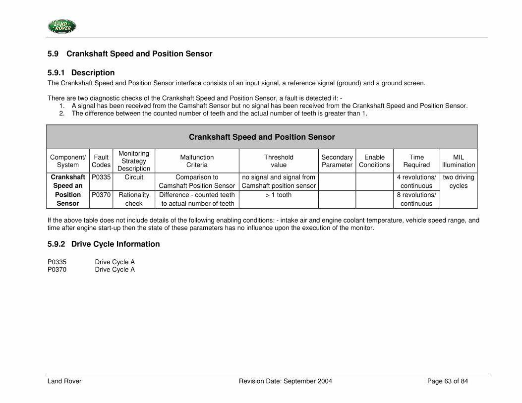
5.9.1 Description The Crankshaft Speed and Position Sensor interface consists of an input signal, a reference signal (ground) and a ground screen. There are two diagnostic checks of the Crankshaft Speed and Position Sensor, a fault is detected if: -
1. A signal has been received from the Camshaft Sensor but no signal has been received from the Crankshaft Speed and Position Sensor. 2. The difference between the counted number of teeth and the actual number of teeth is greater than 1.
Crankshaft Speed and Position Sensor
Component/ System
Fault Codes
Monitoring Strategy
Description
Malfunction Criteria
Threshold value
Secondary Parameter
Enable Conditions
Time Required
MIL Illumination
Crankshaft P0335 Circuit Comparison to no signal and signal from 4 revolutions/ two driving Speed an Camshaft Position Sensor Camshaft position sensor continuous cycles Position P0370 Rationality Difference - counted teeth > 1 tooth 8 revolutions/ Sensor check to actual number of teeth continuous
If the above table does not include details of the following enabling conditions: - intake air and engine coolant temperature, vehicle speed range, and time after engine start-up then the state of these parameters has no influence upon the execution of the monitor.
5.9.2 Drive Cycle Information P0335 Drive Cycle A P0370 Drive Cycle A
Land Rover Revision Date: September 2004 Page 64 of 84
5.10 Camshaft Position Control Interface (VANOS)
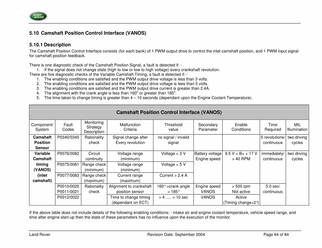
5.10.1 Description The Camshaft Position Control Interface consists (for each bank) of 1 PWM output drive to control the inlet camshaft position, and 1 PWM input signal for camshaft position feedback. There is one diagnostic check of the Camshaft Position Signal, a fault is detected if: -
1. If the signal does not change state (high to low or low to high voltage) every crankshaft revolution. There are five diagnostic checks of the Variable Camshaft Timing, a fault is detected if: -
1. The enabling conditions are satisfied and the PWM output drive voltage is less than 3 volts. 2. The enabling conditions are satisfied and the PWM output drive voltage is lees than 5 volts. 3. The enabling conditions are satisfied and the PWM output drive current is greater than 2.4A. 4. The alignment with the crank angle is less than 160o or greater than 185o. 5. The time taken to change timing is greater than 4 – 10 seconds (dependant upon the Engine Coolant Temperature).
Camshaft Position Control Interface (VANOS)
Component/ System
Fault Codes
Monitoring Strategy
Description
Malfunction Criteria
Threshold value
Secondary Parameter
Enable Conditions
Time Required
MIL Illumination
Camshaft P0340/0345 Rationality Signal change after no signal / invalid 5 revolutions/ two driving Position check Every revolution signal continuous cycles Sensor Variable P0076/0082 Circuit Voltage range Voltage < 3 V Battery voltage 9.5 V < B+ < 17 V immediately/ two driving
Camshaft continuity (minimum) Engine speed > 40 RPM continuous cycles timing P0075/0081 Range check Voltage range Voltage < 5 V
(VANOS) (minimum) (minimum) (inlet P0077/0083 Range check Current range Current > 2.4 A
camshaft) (maximum) (maximum) P0010/0020 Rationality Alignment to crankshaft 160° >crank angle Engine speed > 500 rpm 5.0 sec/ P0011/0021 check position sensor > 185° VANOS Not active continuous P0012/0022 Time to change timing > 4 ..... > 10 sec VANOS Active
(dependant on ECT) (Timing change>2°) If the above table does not include details of the following enabling conditions: - intake air and engine coolant temperature, vehicle speed range, and time after engine start-up then the state of these parameters has no influence upon the execution of the monitor.
Land Rover Revision Date: September 2004 Page 65 of 84
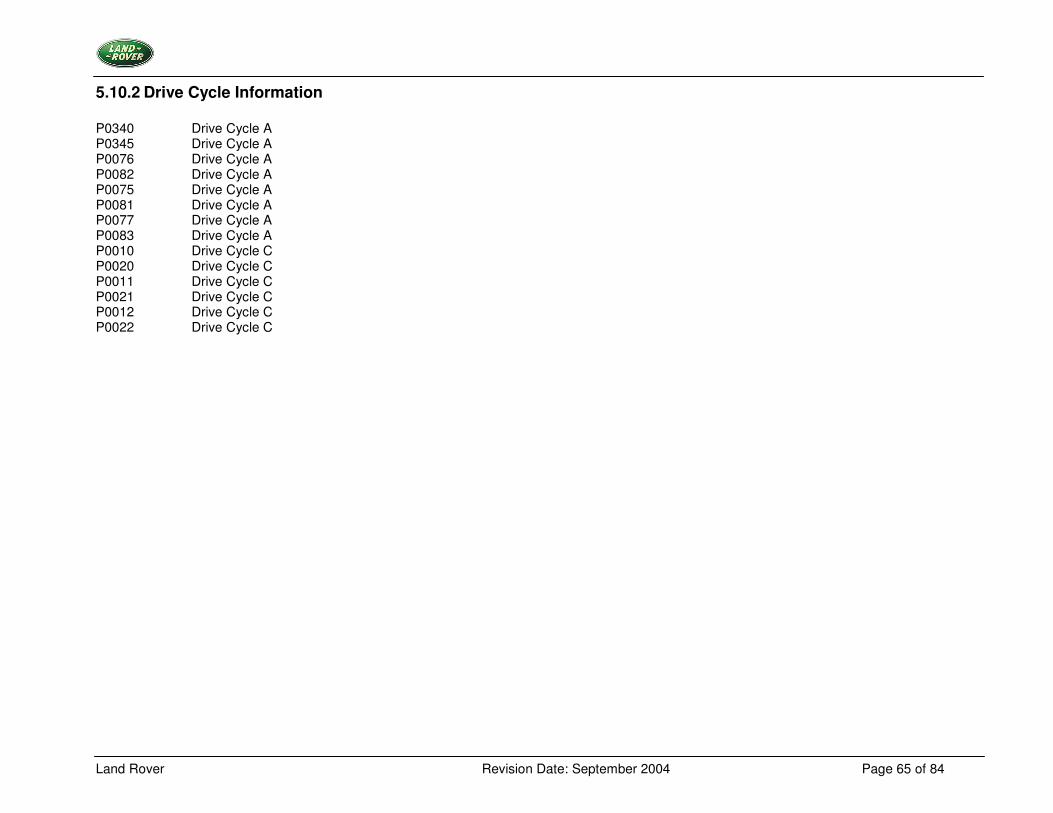
5.10.2 Drive Cycle Information P0340 Drive Cycle A P0345 Drive Cycle A P0076 Drive Cycle A P0082 Drive Cycle A P0075 Drive Cycle A P0081 Drive Cycle A P0077 Drive Cycle A P0083 Drive Cycle A P0010 Drive Cycle C P0020 Drive Cycle C P0011 Drive Cycle C P0021 Drive Cycle C P0012 Drive Cycle C P0022 Drive Cycle C
Land Rover Revision Date: September 2004 Page 66 of 84
5.11 Engine Coolant Temperature Sensor
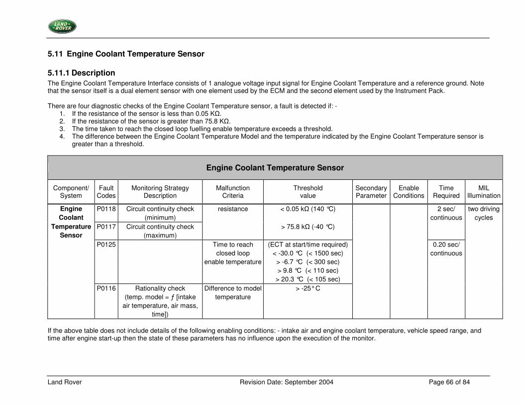
5.11.1 Description The Engine Coolant Temperature Interface consists of 1 analogue voltage input signal for Engine Coolant Temperature and a reference ground. Note that the sensor itself is a dual element sensor with one element used by the ECM and the second element used by the Instrument Pack. There are four diagnostic checks of the Engine Coolant Temperature sensor, a fault is detected if: -
1. If the resistance of the sensor is less than 0.05 K�. 2. If the resistance of the sensor is greater than 75.8 K�. 3. The time taken to reach the closed loop fuelling enable temperature exceeds a threshold. 4. The difference between the Engine Coolant Temperature Model and the temperature indicated by the Engine Coolant Temperature sensor is
greater than a threshold.
Engine Coolant Temperature Sensor
Component/ System
Fault Codes
Monitoring Strategy Description
Malfunction Criteria
Threshold value
Secondary Parameter
Enable Conditions
Time Required
MIL Illumination
Engine P0118 Circuit continuity check resistance < 0.05 k� (140 °C) 2 sec/ two driving Coolant (minimum) continuous cycles
Temperature P0117 Circuit continuity check > 75.8 k� (-40 °C) Sensor (maximum)
P0125 Time to reach (ECT at start/time required) 0.20 sec/ closed loop < -30.0 °C (< 1500 sec) continuous enable temperature > -6.7 °C (< 300 sec)
> 9.8 °C (< 110 sec) > 20.3 °C (< 105 sec) P0116 Rationality check Difference to model > -25° C (temp. model = ƒ [intake temperature air temperature, air mass, time])
If the above table does not include details of the following enabling conditions: - intake air and engine coolant temperature, vehicle speed range, and time after engine start-up then the state of these parameters has no influence upon the execution of the monitor.
Land Rover Revision Date: September 2004 Page 67 of 84
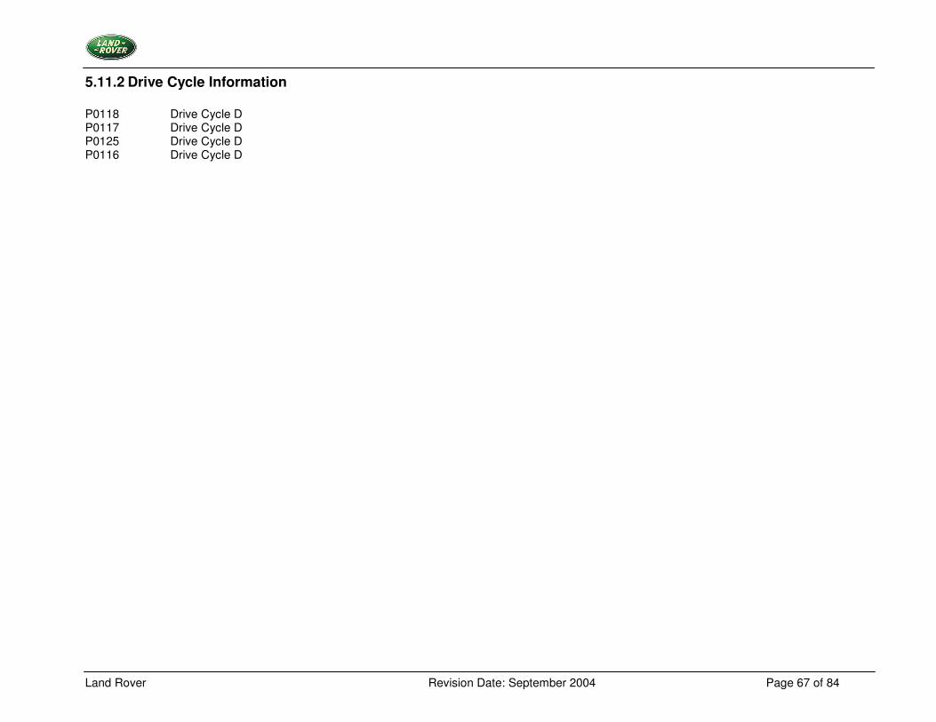
5.11.2 Drive Cycle Information P0118 Drive Cycle D P0117 Drive Cycle D P0125 Drive Cycle D P0116 Drive Cycle D
Land Rover Revision Date: September 2004 Page 68 of 84
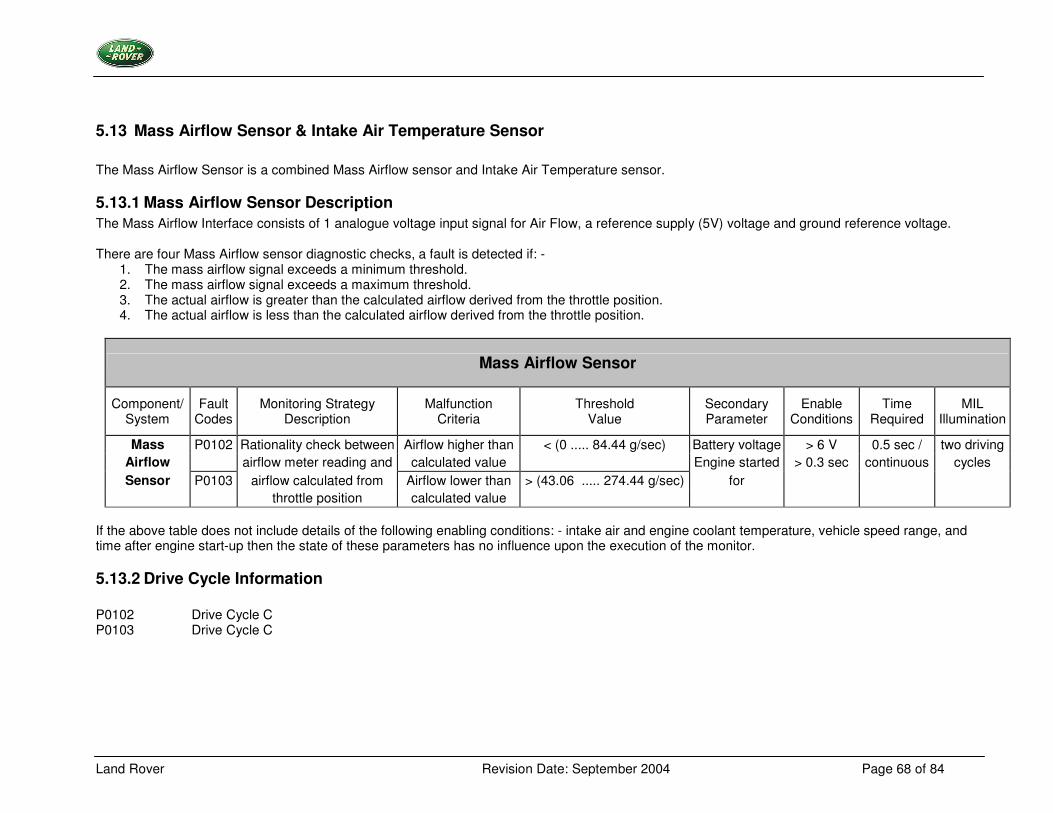
5.13 Mass Airflow Sensor & Intake Air Temperature Sensor The Mass Airflow Sensor is a combined Mass Airflow sensor and Intake Air Temperature sensor.
5.13.1 Mass Airflow Sensor Description The Mass Airflow Interface consists of 1 analogue voltage input signal for Air Flow, a reference supply (5V) voltage and ground reference voltage. There are four Mass Airflow sensor diagnostic checks, a fault is detected if: -
1. The mass airflow signal exceeds a minimum threshold. 2. The mass airflow signal exceeds a maximum threshold. 3. The actual airflow is greater than the calculated airflow derived from the throttle position. 4. The actual airflow is less than the calculated airflow derived from the throttle position.
Mass Airflow Sensor
Component/ System
Fault Codes
Monitoring Strategy Description
Malfunction Criteria
Threshold Value
Secondary Parameter
Enable Conditions
Time Required
MIL Illumination
Mass P0102 Rationality check between Airflow higher than < (0 ..... 84.44 g/sec) Battery voltage > 6 V 0.5 sec / two driving Airflow airflow meter reading and calculated value Engine started > 0.3 sec continuous cycles Sensor P0103 airflow calculated from Airflow lower than > (43.06 ..... 274.44 g/sec) for
throttle position calculated value If the above table does not include details of the following enabling conditions: - intake air and engine coolant temperature, vehicle speed range, and time after engine start-up then the state of these parameters has no influence upon the execution of the monitor.
5.13.2 Drive Cycle Information P0102 Drive Cycle C P0103 Drive Cycle C
Land Rover Revision Date: September 2004 Page 69 of 84
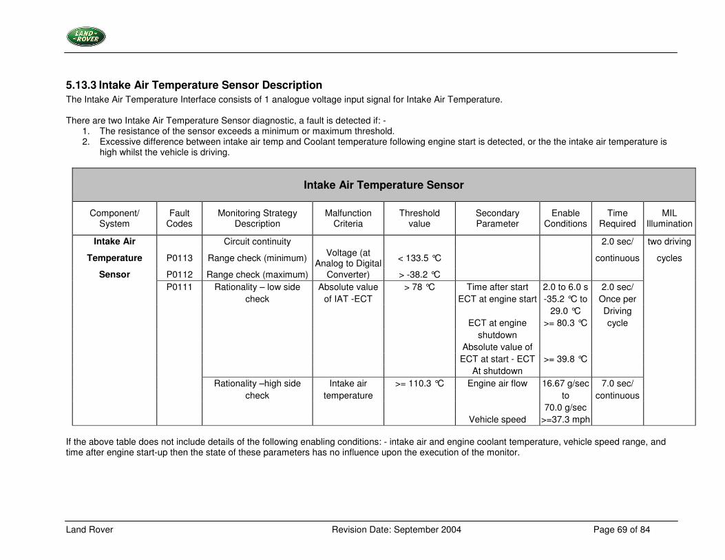
5.13.3 Intake Air Temperature Sensor Description The Intake Air Temperature Interface consists of 1 analogue voltage input signal for Intake Air Temperature. There are two Intake Air Temperature Sensor diagnostic, a fault is detected if: -
1. The resistance of the sensor exceeds a minimum or maximum threshold. 2. Excessive difference between intake air temp and Coolant temperature following engine start is detected, or the the intake air temperature is
high whilst the vehicle is driving.
Intake Air Temperature Sensor
Component/ System
Fault Codes
Monitoring Strategy Description
Malfunction Criteria
Threshold value
Secondary Parameter
Enable Conditions
Time Required
MIL Illumination
Intake Air Circuit continuity 2.0 sec/ two driving
Temperature P0113 Range check (minimum) Voltage (at Analog to Digital < 133.5 °C continuous cycles
Sensor P0112 Range check (maximum) Converter) > -38.2 °C P0111 Rationality – low side Absolute value > 78 °C Time after start 2.0 to 6.0 s 2.0 sec/ check of IAT -ECT ECT at engine start -35.2 °C to Once per 29.0 °C Driving ECT at engine >= 80.3 °C cycle shutdown Absolute value of ECT at start - ECT >= 39.8 °C At shutdown Rationality –high side Intake air >= 110.3 °C Engine air flow 16.67 g/sec 7.0 sec/ check temperature to continuous 70.0 g/sec Vehicle speed >=37.3 mph
If the above table does not include details of the following enabling conditions: - intake air and engine coolant temperature, vehicle speed range, and time after engine start-up then the state of these parameters has no influence upon the execution of the monitor.
Land Rover Revision Date: September 2004 Page 70 of 84
5.13.4 Drive Cycle Information P0112 Drive Cycle B P0113 Drive Cycle B P0111 Drive Cycle B
Land Rover Revision Date: September 2004 Page 71 of 84
5.14 Knock Sensor
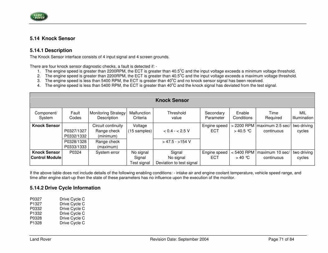
5.14.1 Description The Knock Sensor interface consists of 4 input signal and 4 screen grounds. There are four knock sensor diagnostic checks, a fault is detected if: -
1. The engine speed is greater than 2200RPM, the ECT is greater than 40.5oC and the input voltage exceeds a minimum voltage threshold. 2. The engine speed is greater than 2200RPM, the ECT is greater than 40.5oC and the input voltage exceeds a maximum voltage threshold. 3. The engine speed is less than 5400 RPM, the ECT is greater than 40oC and no knock sensor signal has been received. 4. The engine speed is less than 5400 RPM, the ECT is greater than 40oC and the knock signal has deviated from the test signal.
Knock Sensor
Component/ System
Fault Codes
Monitoring Strategy Description
Malfunction Criteria
Threshold value
Secondary Parameter
Enable Conditions
Time Required
MIL Illumination
Knock Sensor Circuit continuity Voltage Engine speed > 2200 RPM maximum 2.5 sec/ two driving P0327/1327 Range check (15 samples) < 0.4 - < 2.5 V ECT > 40.5 °C continuous cycles P0332/1332 (minimum) P0328/1328 Range check > 47.5 - >154 V
P0333/1333 (maximum) Knock Sensor P0324 System error No signal Signal Engine speed < 5400 RPM maximum 10 sec/ two driving
Control Module Signal No signal ECT > 40 °C continuous cycles Test signal Deviation to test signal
If the above table does not include details of the following enabling conditions: - intake air and engine coolant temperature, vehicle speed range, and time after engine start-up then the state of these parameters has no influence upon the execution of the monitor.
5.14.2 Drive Cycle Information P0327 Drive Cycle C P1327 Drive Cycle C P0332 Drive Cycle C P1332 Drive Cycle C P0328 Drive Cycle C P1328 Drive Cycle C
Land Rover Revision Date: September 2004 Page 72 of 84
P0333 Drive Cycle C P1333 Drive Cycle C P0324 Drive Cycle C
Land Rover Revision Date: September 2004 Page 73 of 84
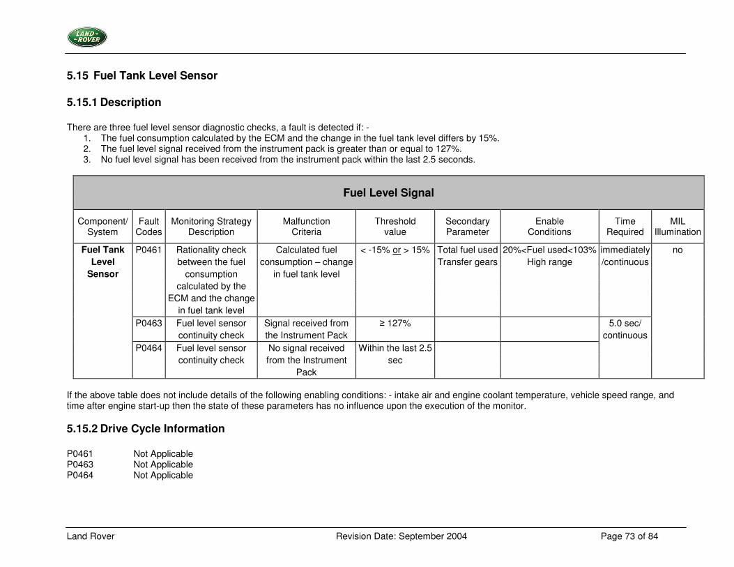
5.15 Fuel Tank Level Sensor
5.15.1 Description There are three fuel level sensor diagnostic checks, a fault is detected if: -
1. The fuel consumption calculated by the ECM and the change in the fuel tank level differs by 15%. 2. The fuel level signal received from the instrument pack is greater than or equal to 127%. 3. No fuel level signal has been received from the instrument pack within the last 2.5 seconds.
Fuel Level Signal
Component/ System
Fault Codes
Monitoring Strategy Description
Malfunction Criteria
Threshold value
Secondary Parameter
Enable Conditions
Time Required
MIL Illumination
Fuel Tank P0461 Rationality check Calculated fuel < -15% or > 15% Total fuel used 20%<Fuel used<103% immediately no Level between the fuel consumption – change Transfer gears High range /continuous
Sensor consumption in fuel tank level calculated by the ECM and the change in fuel tank level P0463 Fuel level sensor Signal received from � 127% 5.0 sec/ continuity check the Instrument Pack continuous
P0464 Fuel level sensor No signal received Within the last 2.5 continuity check from the Instrument sec Pack
If the above table does not include details of the following enabling conditions: - intake air and engine coolant temperature, vehicle speed range, and time after engine start-up then the state of these parameters has no influence upon the execution of the monitor.
5.15.2 Drive Cycle Information P0461 Not Applicable P0463 Not Applicable P0464 Not Applicable
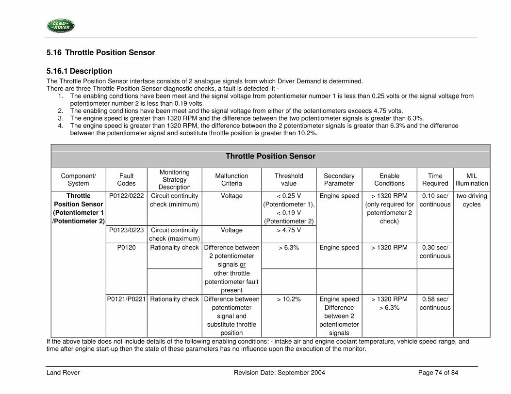
Land Rover Revision Date: September 2004 Page 74 of 84
5.16 Throttle Position Sensor
5.16.1 Description The Throttle Position Sensor interface consists of 2 analogue signals from which Driver Demand is determined. There are three Throttle Position Sensor diagnostic checks, a fault is detected if: -
1. The enabling conditions have been meet and the signal voltage from potentiometer number 1 is less than 0.25 volts or the signal voltage from potentiometer number 2 is less than 0.19 volts.
2. The enabling conditions have been meet and the signal voltage from either of the potentiometers exceeds 4.75 volts. 3. The engine speed is greater than 1320 RPM and the difference between the two potentiometer signals is greater than 6.3%. 4. The engine speed is greater than 1320 RPM, the difference between the 2 potentiometer signals is greater than 6.3% and the difference
between the potentiometer signal and substitute throttle position is greater than 10.2%.
Throttle Position Sensor
Component/ System
Fault Codes
Monitoring Strategy
Description
Malfunction Criteria
Threshold value
Secondary Parameter
Enable Conditions
Time Required
MIL Illumination
Throttle P0122/0222 Circuit continuity Voltage < 0.25 V Engine speed > 1320 RPM 0.10 sec/ two driving Position Sensor check (minimum) (Potentiometer 1), (only required for continuous cycles (Potentiometer 1 < 0.19 V potentiometer 2 /Potentiometer 2) (Potentiometer 2) check)
P0123/0223 Circuit continuity Voltage > 4.75 V check (maximum)
P0120 Rationality check Difference between > 6.3% Engine speed > 1320 RPM 0.30 sec/ 2 potentiometer continuous signals or other throttle potentiometer fault present P0121/P0221 Rationality check Difference between > 10.2% Engine speed > 1320 RPM 0.58 sec/ potentiometer Difference > 6.3% continuous signal and between 2 substitute throttle potentiometer position signals
If the above table does not include details of the following enabling conditions: - intake air and engine coolant temperature, vehicle speed range, and time after engine start-up then the state of these parameters has no influence upon the execution of the monitor.
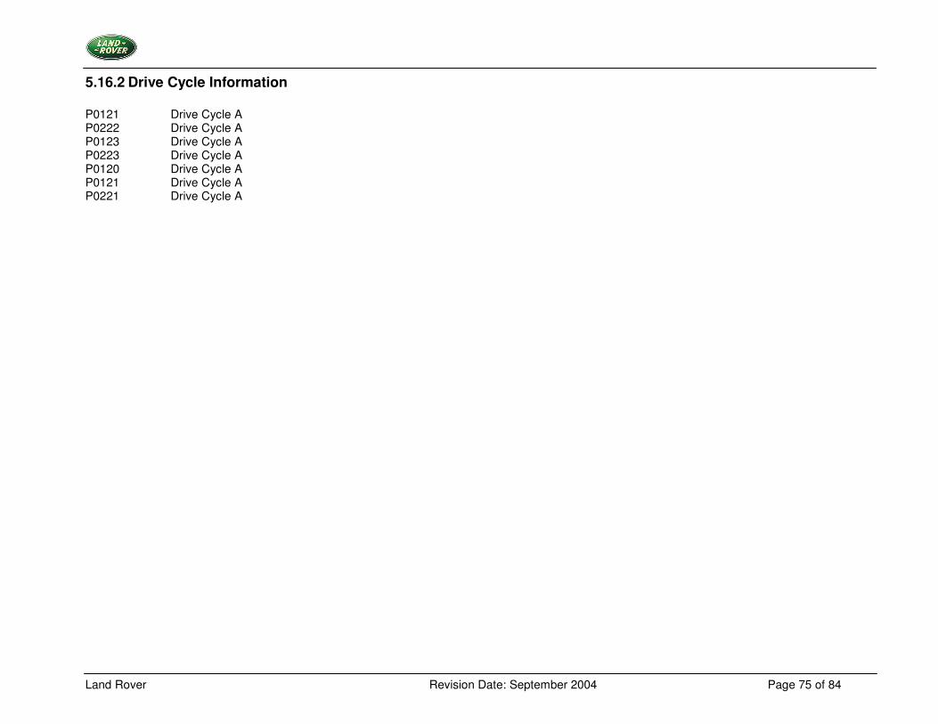
Land Rover Revision Date: September 2004 Page 75 of 84
5.16.2 Drive Cycle Information P0121 Drive Cycle A P0222 Drive Cycle A P0123 Drive Cycle A P0223 Drive Cycle A P0120 Drive Cycle A P0121 Drive Cycle A P0221 Drive Cycle A
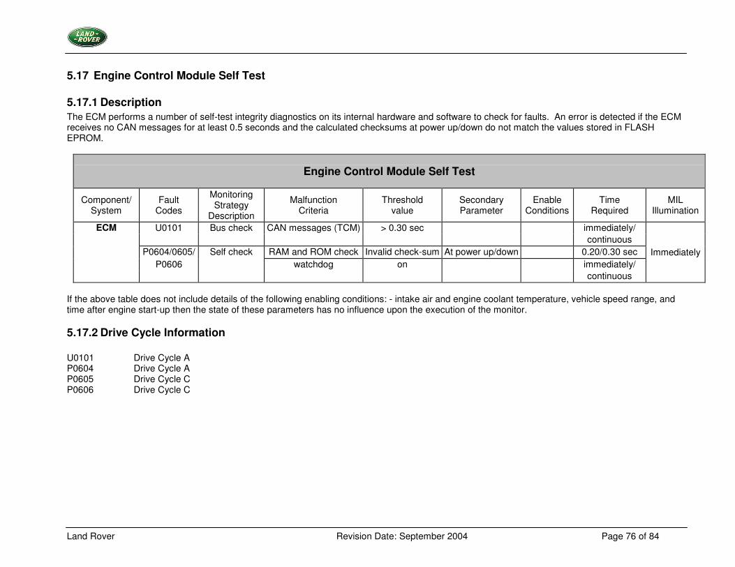
Land Rover Revision Date: September 2004 Page 76 of 84
5.17 Engine Control Module Self Test
5.17.1 Description The ECM performs a number of self-test integrity diagnostics on its internal hardware and software to check for faults. An error is detected if the ECM receives no CAN messages for at least 0.5 seconds and the calculated checksums at power up/down do not match the values stored in FLASH EPROM.
Engine Control Module Self Test
Component/ System
Fault Codes
Monitoring Strategy
Description
Malfunction Criteria
Threshold value
Secondary Parameter
Enable Conditions
Time Required
MIL Illumination
ECM U0101 Bus check CAN messages (TCM) > 0.30 sec immediately/ continuous P0604/0605/ Self check RAM and ROM check Invalid check-sum At power up/down 0.20/0.30 sec Immediately P0606 watchdog on immediately/ continuous
If the above table does not include details of the following enabling conditions: - intake air and engine coolant temperature, vehicle speed range, and time after engine start-up then the state of these parameters has no influence upon the execution of the monitor.
5.17.2 Drive Cycle Information U0101 Drive Cycle A P0604 Drive Cycle A P0605 Drive Cycle C P0606 Drive Cycle C
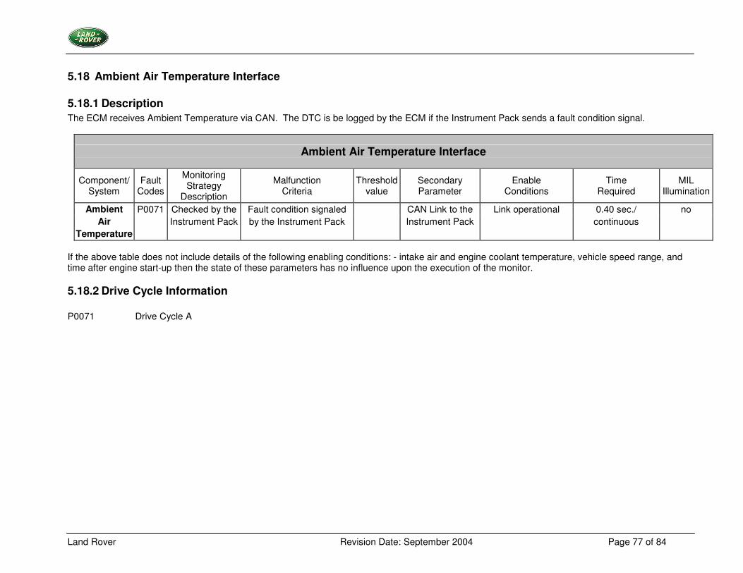
Land Rover Revision Date: September 2004 Page 77 of 84
5.18 Ambient Air Temperature Interface
5.18.1 Description The ECM receives Ambient Temperature via CAN. The DTC is be logged by the ECM if the Instrument Pack sends a fault condition signal.
Ambient Air Temperature Interface
Component/ System
Fault Codes
Monitoring Strategy
Description
Malfunction Criteria
Threshold value
Secondary Parameter
Enable Conditions
Time Required
MIL Illumination
Ambient P0071 Checked by the Fault condition signaled CAN Link to the Link operational 0.40 sec./ no Air Instrument Pack by the Instrument Pack Instrument Pack continuous
Temperature If the above table does not include details of the following enabling conditions: - intake air and engine coolant temperature, vehicle speed range, and time after engine start-up then the state of these parameters has no influence upon the execution of the monitor.
5.18.2 Drive Cycle Information P0071 Drive Cycle A
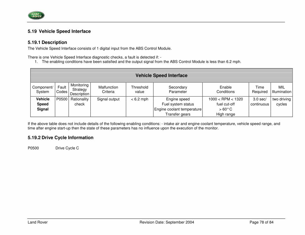
Land Rover Revision Date: September 2004 Page 78 of 84
5.19 Vehicle Speed Interface
5.19.1 Description The Vehicle Speed Interface consists of 1 digital input from the ABS Control Module. There is one Vehicle Speed Interface diagnostic checks, a fault is detected if: -
1. The enabling conditions have been satisfied and the output signal from the ABS Control Module is less than 6.2 mph.
Vehicle Speed Interface
Component/ System
Fault Codes
Monitoring Strategy
Description
Malfunction Criteria
Threshold value
Secondary Parameter
Enable Conditions
Time Required
MIL Illumination
Vehicle P0500 Rationality Signal output < 6.2 mph Engine speed 1000 < RPM < 1320 3.0 sec/ two driving Speed check Fuel system status fuel cut-off continuous cycles Signal Engine coolant temperature > 60° C
Transfer gears High range If the above table does not include details of the following enabling conditions: - intake air and engine coolant temperature, vehicle speed range, and time after engine start-up then the state of these parameters has no influence upon the execution of the monitor.
5.19.2 Drive Cycle Information P0500 Drive Cycle C
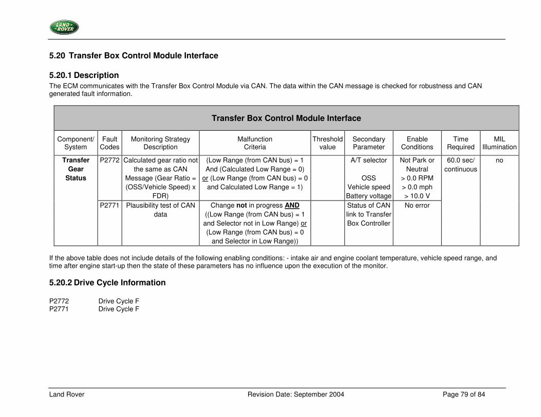
Land Rover Revision Date: September 2004 Page 79 of 84
5.20 Transfer Box Control Module Interface
5.20.1 Description The ECM communicates with the Transfer Box Control Module via CAN. The data within the CAN message is checked for robustness and CAN generated fault information.
Transfer Box Control Module Interface
Component/ System
Fault Codes
Monitoring Strategy Description
Malfunction Criteria
Threshold value
Secondary Parameter
Enable Conditions
Time Required
MIL Illumination
Transfer P2772 Calculated gear ratio not (Low Range (from CAN bus) = 1 A/T selector Not Park or 60.0 sec/ no Gear the same as CAN And (Calculated Low Range = 0) Neutral continuous
Status Message (Gear Ratio = or (Low Range (from CAN bus) = 0 OSS > 0.0 RPM (OSS/Vehicle Speed) x and Calculated Low Range = 1) Vehicle speed > 0.0 mph FDR) Battery voltage > 10.0 V P2771 Plausibility test of CAN Change not in progress AND Status of CAN No error data ((Low Range (from CAN bus) = 1 link to Transfer and Selector not in Low Range) or Box Controller (Low Range (from CAN bus) = 0
and Selector in Low Range)) If the above table does not include details of the following enabling conditions: - intake air and engine coolant temperature, vehicle speed range, and time after engine start-up then the state of these parameters has no influence upon the execution of the monitor.
5.20.2 Drive Cycle Information P2772 Drive Cycle F P2771 Drive Cycle F
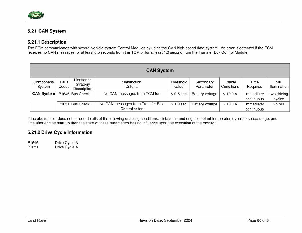
Land Rover Revision Date: September 2004 Page 80 of 84
5.21 CAN System
5.21.1 Description The ECM communicates with several vehicle system Control Modules by using the CAN high-speed data system. An error is detected if the ECM receives no CAN messages for at least 0.5 seconds from the TCM or for at least 1.0 second from the Transfer Box Control Module.
CAN System
Component/ System
Fault Codes
Monitoring Strategy
Description
Malfunction Criteria
Threshold value
Secondary Parameter
Enable Conditions
Time Required
MIL Illumination
CAN System P1646 Bus Check No CAN messages from TCM for > 0.5 sec Battery voltage > 10.0 V immediate/ two driving continuous cycles P1651 Bus Check No CAN messages from Transfer Box > 1.0 sec Battery voltage > 10.0 V immediate/ No MIL Controller for continuous
If the above table does not include details of the following enabling conditions: - intake air and engine coolant temperature, vehicle speed range, and time after engine start-up then the state of these parameters has no influence upon the execution of the monitor.
5.21.2 Drive Cycle Information P1646 Drive Cycle A P1651 Drive Cycle A
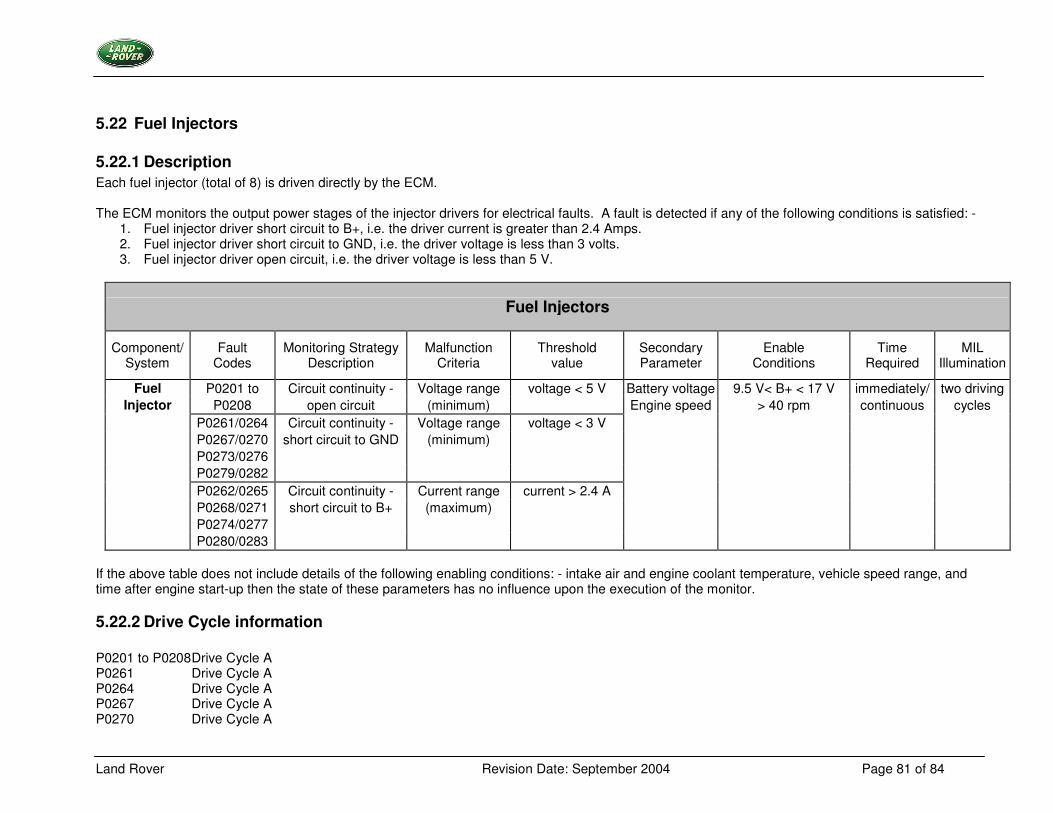
Land Rover Revision Date: September 2004 Page 81 of 84
5.22 Fuel Injectors
5.22.1 Description Each fuel injector (total of 8) is driven directly by the ECM. The ECM monitors the output power stages of the injector drivers for electrical faults. A fault is detected if any of the following conditions is satisfied: -
1. Fuel injector driver short circuit to B+, i.e. the driver current is greater than 2.4 Amps. 2. Fuel injector driver short circuit to GND, i.e. the driver voltage is less than 3 volts. 3. Fuel injector driver open circuit, i.e. the driver voltage is less than 5 V.
Fuel Injectors
Component/ System
Fault Codes
Monitoring Strategy Description
Malfunction Criteria
Threshold value
Secondary Parameter
Enable Conditions
Time Required
MIL Illumination
Fuel P0201 to Circuit continuity - Voltage range voltage < 5 V Battery voltage 9.5 V< B+ < 17 V immediately/ two driving Injector P0208 open circuit (minimum) Engine speed > 40 rpm continuous cycles
P0261/0264 Circuit continuity - Voltage range voltage < 3 V P0267/0270 short circuit to GND (minimum) P0273/0276 P0279/0282 P0262/0265 Circuit continuity - Current range current > 2.4 A P0268/0271 short circuit to B+ (maximum) P0274/0277 P0280/0283
If the above table does not include details of the following enabling conditions: - intake air and engine coolant temperature, vehicle speed range, and time after engine start-up then the state of these parameters has no influence upon the execution of the monitor.
5.22.2 Drive Cycle information P0201 to P0208 Drive Cycle A P0261 Drive Cycle A P0264 Drive Cycle A P0267 Drive Cycle A P0270 Drive Cycle A
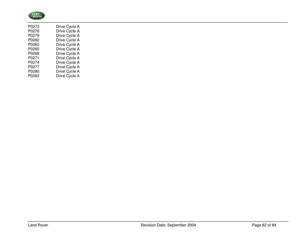
Land Rover Revision Date: September 2004 Page 82 of 84
P0273 Drive Cycle A P0276 Drive Cycle A P0279 Drive Cycle A P0282 Drive Cycle A P0262 Drive Cycle A P0265 Drive Cycle A P0268 Drive Cycle A P0271 Drive Cycle A P0274 Drive Cycle A P0277 Drive Cycle A P0280 Drive Cycle A P0283 Drive Cycle A
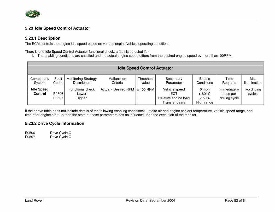
Land Rover Revision Date: September 2004 Page 83 of 84
5.23 Idle Speed Control Actuator
5.23.1 Description The ECM controls the engine idle speed based on various engine/vehicle operating conditions. There is one Idle Speed Control Actuator functional check, a fault is detected if: -
1. The enabling conditions are satisfied and the actual engine speed differs from the desired engine speed by more than100RPM.
Idle Speed Control Actuator
Component/ System
Fault Codes
Monitoring Strategy Description
Malfunction Criteria
Threshold value
Secondary Parameter
Enable Conditions
Time Required
MIL Illumination
Idle Speed Functional check Actual - Desired RPM ± 100 RPM Vehicle speed 0 mph immediately/ two driving Control P0506 Lower ECT > 80° C once per cycles
P0507 Higher Relative engine load < 50% driving cycle Transfer gears High range
If the above table does not include details of the following enabling conditions: - intake air and engine coolant temperature, vehicle speed range, and time after engine start-up then the state of these parameters has no influence upon the execution of the monitor.
5.23.2 Drive Cycle Information P0506 Drive Cycle C P0507 Drive Cycle C
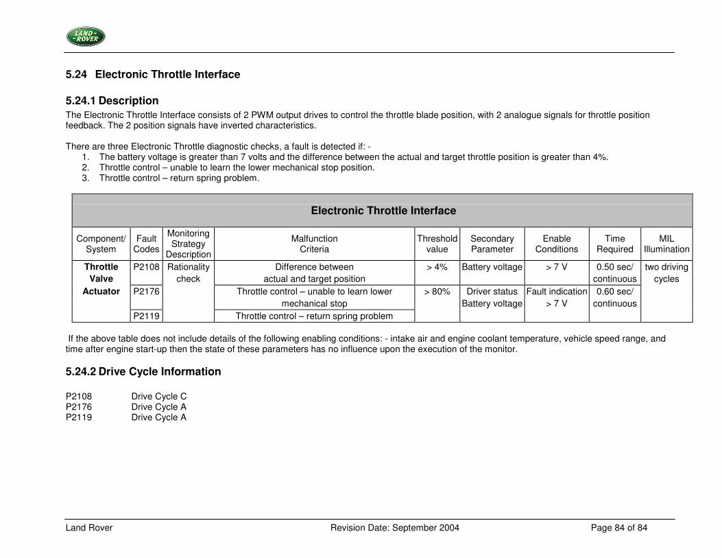
Land Rover Revision Date: September 2004 Page 84 of 84
5.24 Electronic Throttle Interface
5.24.1 Description The Electronic Throttle Interface consists of 2 PWM output drives to control the throttle blade position, with 2 analogue signals for throttle position feedback. The 2 position signals have inverted characteristics. There are three Electronic Throttle diagnostic checks, a fault is detected if: -
1. The battery voltage is greater than 7 volts and the difference between the actual and target throttle position is greater than 4%. 2. Throttle control – unable to learn the lower mechanical stop position. 3. Throttle control – return spring problem.
Electronic Throttle Interface
Component/ System
Fault Codes
Monitoring Strategy
Description
Malfunction Criteria
Threshold value
Secondary Parameter
Enable Conditions
Time Required
MIL Illumination
Throttle P2108 Rationality Difference between > 4% Battery voltage > 7 V 0.50 sec/ two driving Valve check actual and target position continuous cycles
Actuator P2176 Throttle control – unable to learn lower > 80% Driver status Fault indication 0.60 sec/ mechanical stop Battery voltage > 7 V continuous P2119 Throttle control – return spring problem
If the above table does not include details of the following enabling conditions: - intake air and engine coolant temperature, vehicle speed range, and time after engine start-up then the state of these parameters has no influence upon the execution of the monitor.
5.24.2 Drive Cycle Information P2108 Drive Cycle C P2176 Drive Cycle A P2119 Drive Cycle A