Embed Size (px)
Citation preview

Varuvan Vadivelan
Regulation
Branch
Year & Semester
Institute of Technology
ME 6511 - DYNAMICS
Varuvan Vadivelan
Dharmapuri – 636 703
: 2013
: B.E. – MECHANICAL ENGINEERING
: III Year / V Semester
Institute of Technology
LAB MANUAL
DYNAMICS LABORATORY
Varuvan Vadivelan
MECHANICAL ENGINEERING
Institute of Technology
LABORATORY
ME6511- DYNAMICS LABORATORY
DEPARTMENT OF MECHANICAL ENGINEERING Page 2
GENERAL INSTRUCTION
� All the students are instructed to wear protective uniform, shoes &
identity card before entering into the laboratory.
� Before starting the exercise, students should have a clear idea about the
principal of that exercise
� All the students are advised to come with completed record and
corrected observation book of previous experiment.
� Don't operate any instrument without getting concerned staff member's
prior permission.
� The entire instrument is costly. Hence handle them carefully, to avoid
fine for any breakage.
� Utmost care must be taken to avert any possible injury while on
laboratory work. In case, anything occurs immediately report to the
staff members.
� One student form each batch should put his/her signature during
receiving the instrument in instrument issue register.
ME6511- DYNAMICS LABORATORY
DEPARTMENT OF MECHANICAL ENGINEERING Page 3
ANNA UNIVERSITY
REGULATION : 2013
SYLLABUS
LIST OF EXPERIMENTS
1. A) Study of gear parameters.
b) Experimental study of velocity ratios of simple, compound, Epicyclic and differential gear trains.
2. a) Kinematics of Four Bar, Slider Crank, Crank Rocker, Double crank, Double rocker, Oscillating
cylinder Mechanisms.
b) Kinematics of single and double universal joints.
3. a) Determination of Mass moment of inertia of Fly wheel and Axle system.
b) Determination of Mass Moment of Inertia of axisymmetric bodies using Turn Table apparatus.
c) Determination of Mass Moment of Inertia using bifilar suspension and compound pendulum.
4. Motorized gyroscope – Study of gyroscopic effect and couple.
5. Governor - Determination of range sensitivity, effort etc., for Watts, Porter, Proell, and Hartnell
Governors.
6. Cams – Cam profile drawing, Motion curves and study of jump phenomenon
7. a) Single degree of freedom Spring Mass System – Determination of natural Frequency and
verification of Laws of springs – Damping coefficient determination.
b) Multi degree freedom suspension system – Determination of influence coefficient.
8. a) Determination of torsional natural frequency of single and Double Rotor systems.- Undamped
and Damped Natural frequencies.
b) Vibration Absorber – Tuned vibration absorber.
9. Vibration of Equivalent Spring mass system – undamped and damped vibration.
10. Whirling of shafts – Determination of critical speeds of shafts with concentrated loads.
11. a) Balancing of rotating masses.
(b) Balancing of reciprocating masses.
12. a) Transverse vibration of Free-Free beam – with and without concentrated masses.
b) Forced Vibration of Cantilever beam – Mode shapes and natural frequencies.
c) Determination of transmissibility ratio using vibrating table.

ME6511- DYNAMICS LABORATORY
DEPARTMENT OF MECHANICAL ENGINEERING Page 4
INDEX
S.No Date Name of the Experiment Staff
Signature Remarks
1 Transverse vibration of free-beam with & without
concentrated masses
2 Compound Pendulam
3 Whirling Speed of Shaft
4 Vibrating Table
5 Motorized Gyroscope
6 Watt Governor
7 Porter Governor
8 Proell Governor
9 Hartnell Governor
10 Trifilar Suspension (Torsional Pendulum)
11 Bifilar Suspension
12 Experimental Study of Gear Ratio of Differential
Gear Train
13 Experimental Study of Speed Ratio of Compound
Gear Train
14 Experimental Study of Speed Ratio of An Epicyclic
Gear Train
15 Balancing of Reciprocating Masses
16 Balancing of Rotating Masses
17 Study the Profile and Jump Phenomenon of Cam
18 Single Rotor System

ME6511- DYNAMICS LABORATORY
DEPARTMENT OF MECHANICAL ENGINEERING Page 5
TRANSVERSE VIBRATION OF FREE-BEAM WITH & WITHOUT CONCENTRATED
MASSES
Ex. no: 1
Date:
AIM:
To determine the natural frequency of transverse vibration system for different loading
conditions
APPARATUS REQUIRED
I. Transverse vibration setup
II. Weight
TECHNICAL SPECIPICATIONS
Total length of transverse vibration setup = 78 cm
FORMULAE
1. Natural Frequency
F� = ��� �
Hz
�� = �.����√ Hz
Where,
� = deflection in m
2. Stiffness
K = �δ N/m
Where,
w = weight applied in N
� = deflection in mm
PROCEDURE
1. Load the tray in the vibration setup with one block of weight provided.
2. Note down the scale reading and deflection.
3. Repeat the procedures to all the given weight blocks.
4. Plot the graph as corresponding readings.

ME6511- DYNAMICS LABORATORY
DEPARTMENT OF MECHANICAL ENGINEERING Page 6
TABULATION
S.No
Weight Applied (W) in Deflection
Stiffness(k)
N/mm
Natural Frequency
[Fn]
Hz Kg N mm m

ME6511- DYNAMICS LABORATORY
DEPARTMENT OF MECHANICAL ENGINEERING Page 7
GRAPH
1. Load vs Deflection
2. Load vs Natural Frequency
RESULT
Thus the natural frequency of transverse vibration system for different loading condition was
determined by using transverse vibration setup.
1. Stiffness = N/m
2. Natural Frequency = Hz

ME6511- DYNAMICS LABORATORY
DEPARTMENT OF MECHANICAL ENGINEERING Page 8
COMPOUND PENDULAM
Ex. no: 2
Date:
AIM
To determine the radius of gyration and mass moment of inertia of a shaft by compound
pendulum
APPARATUS REQUIRED
1. A Shaft
2. Stopwatch
3. Scale
FORMULA
1. Frequency
�� = �� �� ��������� . Hz
�� = ��� �
� = �.����√� . Hz
Where,
L = Equivalent length of simple pendulum in m
2. Radius of gyration(KG)
� = !�ℎ + ℎ
3. Mass moment of inertia
$ = % !� (kgm2)
Where,
I = mass moment of inertia (kg-m2)
m = mass of pendulum (kg)
ME6511- DYNAMICS LABORATORY
DEPARTMENT OF MECHANICAL ENGINEERING Page 9
PROCEDURE
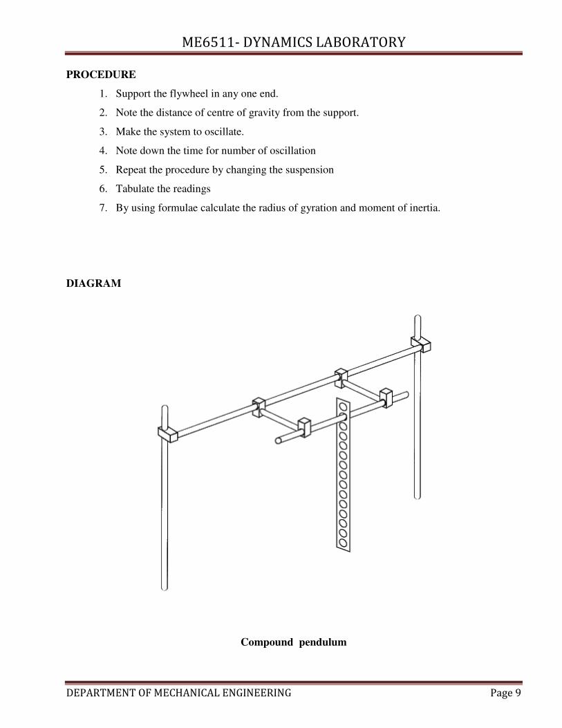
1. Support the flywheel in any one end.
2. Note the distance of centre of gravity from the support.
3. Make the system to oscillate.
4. Note down the time for number of oscillation
5. Repeat the procedure by changing the suspension
6. Tabulate the readings
7. By using formulae calculate the radius of gyration and moment of inertia.
DIAGRAM
Compound pendulum
ME6511- DYNAMICS LABORATORY
DEPARTMENT OF MECHANICAL ENGINEERING Page 10
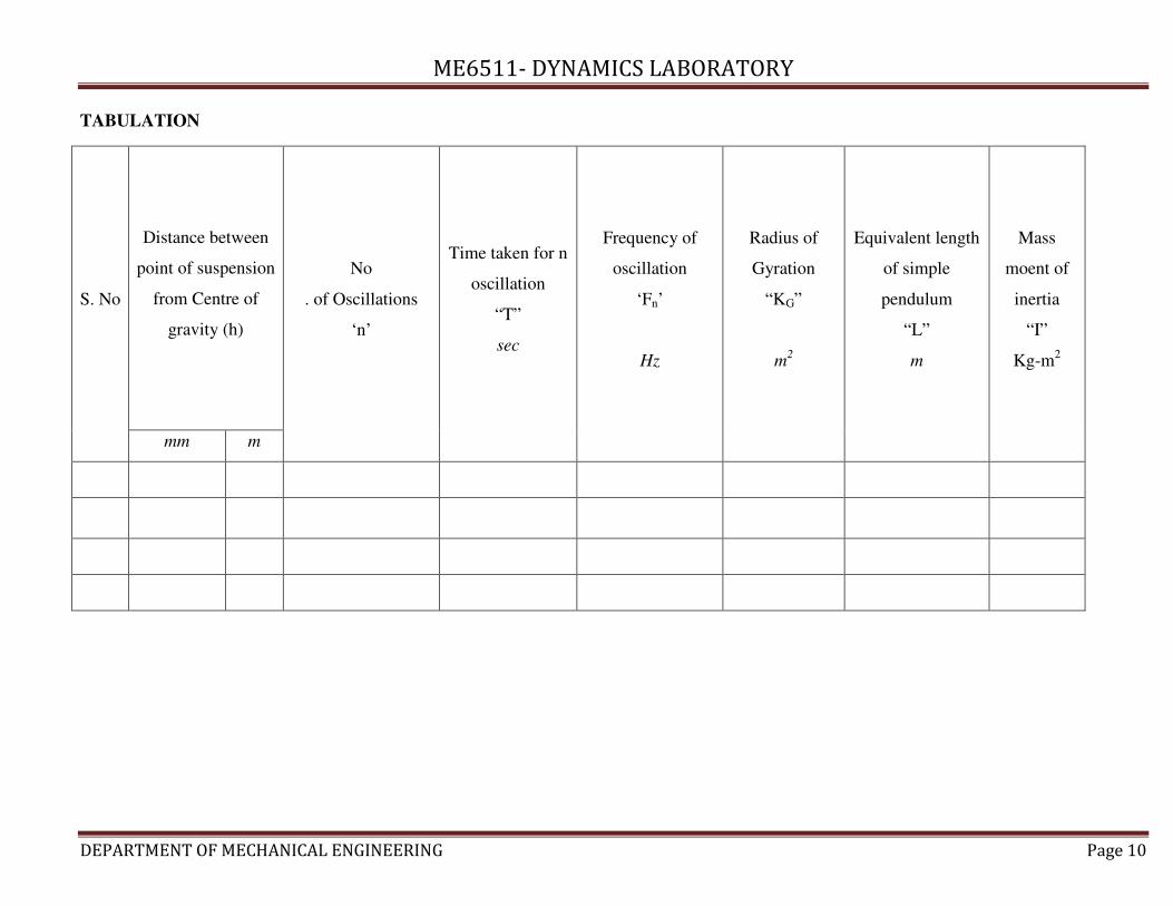
TABULATION
S. No
Distance between
point of suspension
from Centre of
gravity (h)
No
. of Oscillations
‘n’
Time taken for n
oscillation
“T”
sec
Frequency of
oscillation
‘Fn’
Hz
Radius of
Gyration
“KG”
m2
Equivalent length
of simple
pendulum
“L”
m
Mass
moent of
inertia
“I”
Kg-m2
mm m

ME6511- DYNAMICS LABORATORY
DEPARTMENT OF MECHANICAL ENGINEERING Page 11
RESULT
Thus the radius of gyration and Mass moment of inertia for a shaft as compound pendulum is
calculated.

ME6511- DYNAMICS LABORATORY
DEPARTMENT OF MECHANICAL ENGINEERING Page 12
WHIRLING SPEED OF SHAFT
Ex. no: 3
Date:
AIM
To determine the critical speed of shaft of various sizes and to compare it with the theoretical
values
APPARATUS REQUIRED
1. Power source
2. Tachometer (Noncontact type)
3. Vernier caliper
4. Scale
5. Shaft
TECHNICAL SPECIFICATIONS
1. Shaft diameter (d) = 4 mm, 6 mm, 8 mm
2. Length of shaft between ends (l) = 800 mm
3. Density of material of shaft (&) = 8000 kg/m3
4. Young’s modulus(E) = 2.1 x 10¹¹
N/m2
FORMULAE
1. Moment of inertia of shaft
$ = �'()� (mm
4)
Where,
d= diameter of the shaft (m)
2. Mass of shaft per meter length
*� = + × - × &
Where,
A= area of shaft (m2)
+ = �'.� (mm
2)
l = length of shaft (m)
& = density of shaft material (kg/m3)

ME6511- DYNAMICS LABORATORY
DEPARTMENT OF MECHANICAL ENGINEERING Page 13
3. Static deflection due to mass of shaft
�� = /�(0��12. (m)
Where,
W – Weight of the shaft (N)
4. Frequency
�� = �.����� 34
5..6. Hz
5. Whirling speed of shaft
Ncr = frequency of shaft in rps
6. Efficiency of whirling shaft
7 = +89:;- 8<=9=8;- >?@@ABℎ@<C9=8;- >?@@A × 100
PROCEDURE
1. Take the shaft of difference diameter as 4, 6 and 8 mm
2. To fix the shaft at both ends
3. Switch on the motor and increase the speed
4. Note down the speed at which the vibration is maximum using tachometer
5. This speed is known as critical speed (or) wire ling speed
6. Repeat the same procedure for all shaft
7. Tabulate the readings and calculate the theoretical value
8. Compare the experimental value with theoretical value

ME6511- DYNAMICS LABORATORY
DEPARTMENT OF MECHANICAL ENGINEERING Page 14
DIAGRAM

ME6511- DYNAMICS LABORATORY
DEPARTMENT OF MECHANICAL ENGINEERING Page 15
TABULATION
S. No
Diameter of the shaft Diameter of shaft both 2
ends Actual
critical
speed
Rpm
Deflection
m
Theoretical critical
speed
(Ncr)
rpm
Efficiency
%
mm m mm m
1
2
3

ME6511- DYNAMICS LABORATORY
DEPARTMENT OF MECHANICAL ENGINEERING Page 16
RESULT
Thus the actual critical speed of the shaft is found out by tachometer and compared with the
theoretical speed and the efficiency of whirling of shaft is obtained.

ME6511- DYNAMICS LABORATORY
DEPARTMENT OF MECHANICAL ENGINEERING Page 17
VIBRATING TABLE
Ex. no: 4
Date:
AIM
To determine the transmissibility of forced vibrations and to analyses all types of vibrations
with its frequency and amplitude.
APPARATUS REQUIRED
1. Vibrating table setup
2. Dimmer set with speedometer
3. Stopwatch
4. Recorder
TECHNICAL SPECIFICATION
Mass of beam = 1.6 kg
Total length of beam [L] = 1 m
Mass of the exciter [M] = 5.4 kg
Stiffness of spring [k] = 1.968 N/m
Radius of the exciter [r] = 0.07 m
FORMULA
1. Frequency
�� = �� �� ���F��GHF���HFI� HGJ�� . Hz
2. Natural frequency
K� = ��� �
= �.����√ . Hz
where,
� = maximum deflection in m
3. Maximum force transmitted
�LM = >9=NNO@>> CN 9ℎ@ >?<=OP × max A@N-@89=CO

ME6511- DYNAMICS LABORATORY
DEPARTMENT OF MECHANICAL ENGINEERING Page 18
4. Maximum impressed force
� = %T�< (N)
Where,
m = mass of beam + mass of exciter
m = M + me
r = radius of exciter
U = angular velocity
5. Transmissibility
∈= �LM�
Where,
FTR = Maximum force transmitted (N)
F = Maximum impressed force (N)
PROCEDURE
1. Attach the vibrating recorder at suitable position with the pen or pencil holder slightly pressing
paper.
2. Attach the damper with unit to stud.
3. Start the exciter motor and set at required speed and start the recorder motor
4. Now vibrations are recorded over the vibration recorder. Increase the speed and note the
vibration.
5. At the resonance speed the amplitude of vibrations may be recorded as merged one another.
6. Hold the system and cross the speed little more than the response speed.
7. Analyse the recorded frequency and amplitude for both damped and undamped force
vibrations.

ME6511- DYNAMICS LABORATORY
DEPARTMENT OF MECHANICAL ENGINEERING Page 19
DIAGRAM
Vibrating table
GRAPH
1. Speed vs Transmissibility
2. Speed vs Natural frequency

ME6511- DYNAMICS LABORATORY
DEPARTMENT OF MECHANICAL ENGINEERING Page 20
TABUALTION
S.
No
Speed of
motor
n (rpm)
Time taken for
10 oscillations
(Sec)
Maximum
amplitude
(m)
Frequency
(Hz)
Natural
frequency
(Hz)
Maximum
force
transmitted
(N)
Maximum
impressed
force
(N)
Transmissibility

ME6511- DYNAMICS LABORATORY
DEPARTMENT OF MECHANICAL ENGINEERING Page 21
RESULT
Thus the transmissibility of forced vibrations and types of vibrations with its frequency of
amplitude are analysed.

ME6511- DYNAMICS LABORATORY
DEPARTMENT OF MECHANICAL ENGINEERING Page 22
MOTORIZED GYROSCOPE
Ex. no: 5
Date:
AIM
To determine the gyroscopic couple of rotating masses and to verify the gyroscope rules of a
plane rotating disc.
APPARATUS REQUIRED
1. Tachometer (contact type)
2. Set of weights
3. Dimmer set and power supply
4. Stop watch
TECHNICAL SPECIFICATIONS
Mass of the rotor =7 kg
Rotor diameter (D) = 300 mm
Rotor thickness (t) = 8 mm
Bolt size = MI 08
FORMULAE
1. Angle of precision
W = W × X180
Where,
W = Angle of precision (degrees)
2. Angular velocity of precision
TZ = '['H = [
H rad/s
3. Angular velocity
U = ���)� rad/s
Where,
N = Speed of the motor (rpm)

ME6511- DYNAMICS LABORATORY
DEPARTMENT OF MECHANICAL ENGINEERING Page 23
4. Moment of inertia of disc
$ = I\.� kgm
2
Where,
m = mass of the disc (kg)
r = radius of disc (m)
5. Gyroscopic couple (N-m)
] = $UUZ (Nm)
PROCEDURE
1. Switch on the supply
2. Set the required speed by the regulator at constant
3. Add the load viz ½ kg, 1 kg,…
4. Loose the lock screw, start the stopwatch and note down.
5. Watch the angular displacement at particular time interval.
6. Take the readings for different loads.
DIAGRAM

ME6511- DYNAMICS LABORATORY
DEPARTMENT OF MECHANICAL ENGINEERING Page 24
TABULATION
S. No Speed of motor
(rpm)
Weight applied
(N)
Time taken for
precision
(Sec)
Angle of precision Angular velocity
of precision (Wp)
Gyroscopic couple
C
(Nm) Degree Rad
ME6511- DYNAMICS LABORATORY
DEPARTMENT OF MECHANICAL ENGINEERING Page 25
RESULT
Thus the value of gyroscopic couple of rotating masses and gyroscopic rules of a plane rotating
disc was verified.

ME6511- DYNAMICS LABORATORY
DEPARTMENT OF MECHANICAL ENGINEERING Page 26
WATT GOVERNOR
Ex. no:6
Date:
AIM
To determine the stability and controlling force of watt governor
APPARATUS REQUIRED
1. Governor setup
2. Speed regulator
3. Tachometer
4. Dead weight
OBSERVATION
Length of upper arm L1 =
Length of lower arm L2 =
Weight of ball Wb =
Weight of sleeve Ws =
FORMULA
1. Angular velocity
U = ���)� rad/s
2. Height of the sleeve
ℎ = ^. (m)
Where,
g = acceleration due to gravity (m/s2)
3. Theoretical speed
KH_ = ����_ (rpm)
4. Centrifugal force
�̀ = I\_ (N)
Where,
m = mass of the ball = 0.31 kg
r = radius of sleeve (m)
ME6511- DYNAMICS LABORATORY
DEPARTMENT OF MECHANICAL ENGINEERING Page 27
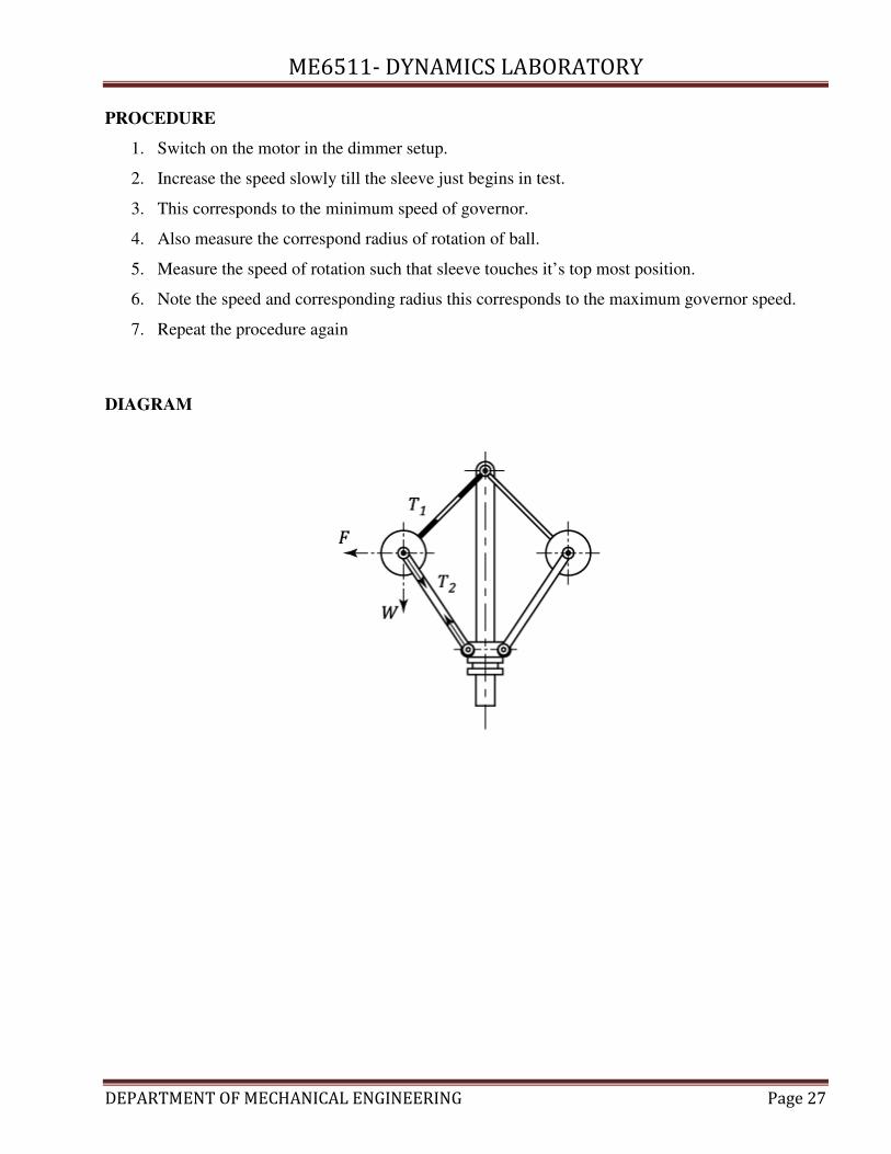
PROCEDURE
1. Switch on the motor in the dimmer setup.
2. Increase the speed slowly till the sleeve just begins in test.
3. This corresponds to the minimum speed of governor.
4. Also measure the correspond radius of rotation of ball.
5. Measure the speed of rotation such that sleeve touches it’s top most position.
6. Note the speed and corresponding radius this corresponds to the maximum governor speed.
7. Repeat the procedure again
DIAGRAM

ME6511- DYNAMICS LABORATORY
DEPARTMENT OF MECHANICAL ENGINEERING Page 28
TABULATION
S. No Observed speed Lift
(m) Sleeve radius (r) Sleeve height (h)
Theoretical speed
(rpm) Centrifugal force (F)

ME6511- DYNAMICS LABORATORY
DEPARTMENT OF MECHANICAL ENGINEERING Page 29
RESULT
Thus the stability and controlling force of watt governor was determined.

ME6511- DYNAMICS LABORATORY
DEPARTMENT OF MECHANICAL ENGINEERING Page 30
PORTER GOVERNOR
Ex. no: 7
Date:
AIM
To determine the stability and controlling force of the porter governor
APPARATUS REQUIRED
1. Governor setup
2. Speed regulator
3. Tachometer
4. Dead weights
FORMULA USED
1. Angular velocity
U = ���)� rad/s
2. Height of the sleeve
ℎ = IabI ×
^. (m)
3. Theoretical speed
KH_ = �I×bI + ���
_ (rpm)
4. Centrifugal force
�̀ = %U�< (N)
Where,
l = upper arm length (m)
r = radius (m)
m = mass of the ball = 0.31 kg
M = mass of sleeve = 1 kg
5. Range of the governor (R)
c = %;d=%:% >?@@A − %=O=%:% >?@@A
6. Sensitivity of the governor
>@O>=9=f=9g = 2 × %;d. >?@@A − %=O. >?@@A%;d. >?@@A + %=O. >?@@A × 100

ME6511- DYNAMICS LABORATORY
DEPARTMENT OF MECHANICAL ENGINEERING Page 31
7. Percentage increase in speed
] = K� − K�K�
Where,
N2 = Maximum speed
N1 = Minimum speed
PROCEDURE
1. Switch on the motor in dimmer setup
2. Increase the speed slowly till the sleeve just begins in test
3. This corresponds to minimum speed of the governor
4. Also measure the corresponding radius of rotation of ball
5. Measure the speed of rotation such that the sleeve touches it’s topmost position
6. Note the speed and corresponding radius, this corresponds to the maximum governor
speed
7. Repeat the procedure again
DIAGRAM

ME6511- DYNAMICS LABORATORY
DEPARTMENT OF MECHANICAL ENGINEERING Page 32
TABULATION
S. No Lift
(M)
Sleeve radius r
(m)
Sleeve height h
(m)
Theoretical speed
(RPM)
Centrifugal force F
(N)

ME6511- DYNAMICS LABORATORY
DEPARTMENT OF MECHANICAL ENGINEERING Page 33
RESULT
Thus the stability and controlling force of porter governor was determined.

ME6511- DYNAMICS LABORATORY
DEPARTMENT OF MECHANICAL ENGINEERING Page 34
PROELL GOVERNOR
Ex. no: 8
Date:
AIM
To determine the stability and controlling force of proell governor
APPARATUS REQUIRED
1. Governor setup
2. Speed regulator
3. Tachometer
4. Dead weights
OBSERVATION
1. Length of the upper arm L1 = 155 mm
2. Extension of the lower link = 110 mm
3. Weight of the ball Wb = 0.31 kg
4. Weight of the sleeve Ws = 1.25 kg
FORMULA USED
1. Angular velocity
U = ���)� rad/s
2. Theoretical speed
KH_ = �ibjb
IabI
�k�_ (rpm)
3. Centrifugal force
�̀ = %U�< (N)
Where,
l = upper arm length (m)
r = radius (m)
m = mass of the ball = 0.31 kg
M = mass of sleeve = 1 kg
4. Range of the governor (R)
c = %;d=%:% >?@@A − %=O=%:% >?@@A

ME6511- DYNAMICS LABORATORY
DEPARTMENT OF MECHANICAL ENGINEERING Page 35
5. Sensitivity of the governor
>@O>=9=f=9g = 2 × %;d. >?@@A − %=O. >?@@A%;d. >?@@A + %=O. >?@@A × 100
6. Percentage increase in speed
] = K� − K�K�
Where,
N2 = Maximum speed
N1 = Minimum speed
PROCEDURE
1. Switch on the motor in dimmer setup
2. Increase the speed slowly till the sleeve just begins in test
3. This corresponds to minimum speed of the governor
4. Also measure the corresponding radius of rotation of ball
5. Measure the speed of rotation. Such that the sleeve touches it’s top most position
6. Note the speed and corresponding radius. This corresponds to the maximum governor speed.
7. Repeat the procedure again
DIAGRAM
ME6511- DYNAMICS LABORATORY
DEPARTMENT OF MECHANICAL ENGINEERING Page 36
TABULATION
S. No Lift
(m) Sleeve radius r (m)
Sleeve height h
(m)
Theoretical speed
(rpm)
Centrifugal force F
(N)

ME6511- DYNAMICS LABORATORY
DEPARTMENT OF MECHANICAL ENGINEERING Page 37
RESULT
Thus the stability and controlling force of the proell governor was determined.

ME6511- DYNAMICS LABORATORY
DEPARTMENT OF MECHANICAL ENGINEERING Page 38
HARTNELL GOVERNOR
Ex. no: 9
Date:
AIM
To determine the stability and controlling forces of hartnell governor
APPARATUS REQUIRED
1. Governor setup
2. Speed regulator
3. Tachometer
4. Dead weight
OBSERVATION
Length of Horizontal arm Y = 160 mm
Length of vertical arm X = 200 mm
Mass of the Ball (m) = 0.311 kg
FORMULA USED
1. Angular velocity
U = ���)� rad/s
2. Height of sleeve (h)
ℎ = (<� − <�)(g dn ) m
where,
x = length of vertical arm (m)
y = length of horizontal arm (m)
3. Centrifugal force (Fc)
�̀ = %U�< (N)
4. Spring force for lowest position
o� = 2�̀ � × p� (N)
5. Spring force for highest position
o� = 2�̀ � × p� (N)

ME6511- DYNAMICS LABORATORY
DEPARTMENT OF MECHANICAL ENGINEERING Page 39
6. Stiffness of spring (S)
o = q.rq5_ (N/m)
PROCEDURE
1. Switch on the motor in dimmer setup
2. Increase the speed slowly till the sleeve just begins in test
3. This corresponds to minimum speed of the governor
4. Also measure the corresponding radius of rotation of ball
5. Measure the speed of rotation. Such that the sleeve touches it’s top most position
6. Note the speed and corresponding radius. This corresponds to the maximum governor speed.
7. Repeat the procedure again
DIAGRAM

ME6511- DYNAMICS LABORATORY
DEPARTMENT OF MECHANICAL ENGINEERING Page 40
TABULATION
S. No Lift
(mm) Sleeve radius (r) Sleeve height (h)
Theoretical speed
(rpm)
Centrifugal force F
(N)

ME6511- DYNAMICS LABORATORY
DEPARTMENT OF MECHANICAL ENGINEERING Page 41
RESULT
Thus the stability and controlling force of the Hartnell governor was determined.

ME6511- DYNAMICS LABORATORY
DEPARTMENT OF MECHANICAL ENGINEERING Page 42
TRIFILAR SUSPENSION
(TORSIONAL PENDULUM)
Ex. no: 10
Date:
AIM
To determine the radius of gyration and mass moment of inertia of the circular disc by trifilar
suspension
APPARATUS REQUIRED
1. A circular disc
2. Stop watch
3. Scale
OBSERVATION
1. Distance of each wire from the axis of disc (r) = 0.055 m
2. Length of each wire (l) = 0.5 m
3. Mass of the disc (m) = 1 kg
FORMULAE
1. Frequency of oscillation (n)
O = ��.�� ���F��GHF��� LFI� HGJ�� Hz
2. Also frequency of oscillation (n)
O = \��st �
� Hz
Where,
KG = Radius of gyration of disc (m)
3. Moment of inertia of disc (I)
$ = % !� (kgm2)

ME6511- DYNAMICS LABORATORY
DEPARTMENT OF MECHANICAL ENGINEERING Page 43
PROCEDURE
1. Support the disc in any one end
2. Note the distance between the suspension and center of gravity
3. Make the system to oscillate
4. Note down the time for number of oscillation
5. Repeat the procedure by changing the suspension
6. Tabulate the readings
7. By using formulae calculate radius of gyration and moment of inertia

ME6511- DYNAMICS LABORATORY
DEPARTMENT OF MECHANICAL ENGINEERING Page 44
TABUALTION
S.
No
No. of oscillations
(n)
Time taken for ‘n’
oscillation
(sec)
Frequency of
oscillation
(Hz)
Radius of gyration
(KG)
Mass moment of inertia
I
(kgm2)

ME6511- DYNAMICS LABORATORY
DEPARTMENT OF MECHANICAL ENGINEERING Page 45
DIAGRAM
Trifilar suspension
RESULT
Thus the radius of gyration and mass moment of inertia for disc Trifilar suspension is
calculated.
Radius of Gyration KG = m
Mass moment of Inertia I = kgm2

ME6511- DYNAMICS LABORATORY
DEPARTMENT OF MECHANICAL ENGINEERING Page 46
BIFILAR SUSPENSION
Ex. no: 11
Date:
AIM
To determine the radius of gyration and mass moment of inertia of a rectangular bar by Bifillar
suspension
APPARATUS REQUIRED
1. A shaft (or) Rectangular bar
2. Stop watch
3. Scale
OBSERVATION
Distance of A from G = 0.155 m
Distance of B from G = 0.155 m
Length of each spring (l) = 0.485 m
Mass of the rectangular bar (m) = 0.88 kg
FORMULA
1. Frequency of oscillation (Fn)
�� = ��.�� ���F��GHF��LFI� HGJ�� . (Hz)
2. Also frequency of oscillation
�� = ���st �p�
� . (Hz)
Where,
KG = radius of gyration
g = acceleration due to gravity
x = distance of A from G = 0.155 m
y = distance of B from G = 0.155 m
l = length of each string = 0.435 m
3. Mass moment of inertia (I)
$ = % !�
Where, m = Mass of rectangular bar = 0.88 kg

ME6511- DYNAMICS LABORATORY
DEPARTMENT OF MECHANICAL ENGINEERING Page 47
PROCEDURE
1. A rectangular bar is taken and it is suspended at both the end by two flexible strings.
2. The whole setup is attached to a fixed support
3. The system is made to oscillate and the time taken is calculated for number of oscillation
4. The readings are tabulated and radius of gyration and mass moment inertia is calculated.
DIAGRAM
Bifilar suspension

ME6511- DYNAMICS LABORATORY
DEPARTMENT OF MECHANICAL ENGINEERING Page 48
TABUALTION
S.
No No. of oscillations
Time taken for ‘n’
oscillation
(sec)
Frequency of
oscillation
(Hz)
Radius of gyration
(KG)
Mass moment of inertia
(I)

ME6511- DYNAMICS LABORATORY
DEPARTMENT OF MECHANICAL ENGINEERING Page 49
RESULT
Thus the radius of gyration and the mass moment of inertia of rectangular bar is calculated by
bifilar suspension.
Radius of Gyration, KG = m
Mass moment of inertia, I = kgm2

ME6511- DYNAMICS LABORATORY
DEPARTMENT OF MECHANICAL ENGINEERING Page 50
EXPERIMENTAL STUDY OF GEAR RATIO OF DIFFERENTIAL GEAR TRAIN
Ex. no: 12
Date:
AIM
To conduct the experimental study of gear ratio of differential gear train
APPARATUS REQUIRED
1. Differential gear train
2. Digital speed indicator
3. Speed transformer
FORMULA USED
1. Total reduction speed in
Right Wheel (NR) = �5r�.
�5 × 100 in %
Left Wheel (NL) = �5r�.
�5 × 100 in %
Where,
N1 = Input speed in rpm
N2 = Output speed in rpm
2. Speed ratio
Right wheel (NR) = N1/N2
Left wheel (NL) = N1/N2
PROCEDURE
1. Connect the main chord to the 230 V, 50 Hz power supply
2. Connect the sensor 1 and sensor 2 to the respective sensor sockets provided on the front
panel of electronic speed control system.
3. Connect the motor cable to the terminal socket
4. Initially keep variable speed control knob is closed position
5. Switch on the instrument
6. Adjust the speed by tuning the knob and tabulate the readings and calculate.

ME6511- DYNAMICS LABORATORY
DEPARTMENT OF MECHANICAL ENGINEERING Page 51
TABULATION
S. No Input speed
(N1)
Output Speed
(N2) rpm Total reduction in speed (N) in % Speed ratio
Right wheel
NR
Left wheel
Nl
Right wheel
NR
Left wheel
Nl
Right wheel
NR
Left wheel
Nl
1
2
3
ME6511- DYNAMICS LABORATORY
DEPARTMENT OF MECHANICAL ENGINEERING Page 52
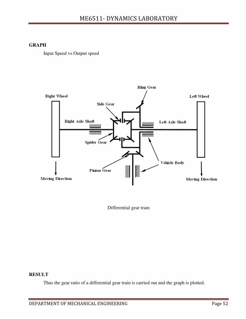
GRAPH
Input Speed vs Output speed
Differential gear train
RESULT
Thus the gear ratio of a differential gear train is carried out and the graph is plotted.

ME6511- DYNAMICS LABORATORY
DEPARTMENT OF MECHANICAL ENGINEERING Page 53
EXPERIMENTAL STUDY OF SPEED RATIO OF COMPOUND GEAR TRAIN
Ex. no: 13
Date:
AIM
To conduct the experimental study of speed ratio of an compound gear train
APPARATUS REQUIRED
- Compound gear train
- Digital speed indicator
- Speed transformer
FORMULA USED
1. Total reduction speed (N)
K = K� − K�K�
× 100 %
Where,
N1 = Input speed in rpm
N2 = Output speed in rpm
2. Speed ratio = N1/N2
PROCEDURE
1. Connect the main chord to the 230 V, 50 Hz power supply
2. Connect the sensor 1 and sensor 2 to the respective sensor sockets provided on the front
panel of electronic speed control system.
3. Connect the motor cable to the terminal socket
4. Initially keep variable speed control knob is closed position
5. Switch on the instrument
6. Adjust the speed by tuning the knob and tabulate the readings and calculate.
GRAPH
Input speed vs Output speed

ME6511- DYNAMICS LABORATORY
DEPARTMENT OF MECHANICAL ENGINEERING Page 54
DIAGRAM
`
Compound gear train
ME6511- DYNAMICS LABORATORY
DEPARTMENT OF MECHANICAL ENGINEERING Page 55
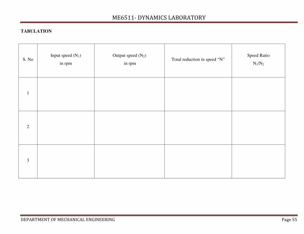
TABULATION
S. No Input speed (N1)
in rpm
Output speed (N2)
in rpm Total reduction in speed “N”
Speed Ratio
N1/N2
1
2
3

ME6511- DYNAMICS LABORATORY
DEPARTMENT OF MECHANICAL ENGINEERING Page 56
RESULT
Thus the speed ratio of an compound gear reducer is carried out and the graph is plotted.

ME6511- DYNAMICS LABORATORY
DEPARTMENT OF MECHANICAL ENGINEERING Page 57
EXPERIMENTAL STUDY OF SPEED RATIO OF AN EPICYCLIC GEAR TRAIN
Ex. no: 14
Date:
AIM
To conduct the experimental study of speed ratio of an epicyclic gear train
APPARATUS REQUIRED
- Epicyclic gear train
- Digital speed indicator
- Speed transformer
FORMULA USED
1. Total reduction speed (N)
K = K� − K�K�
× 100 %
Where,
N1 = Input speed in rpm
N2 = Output speed in rpm
2. Speed ratio = N1/N2
PROCEDURE
1. Connect the main chord to the 230 V, 50 Hz power supply
2. Connect the sensor 1 and sensor 2 to the respective sensor sockets provided on the front
panel of electronic speed control system.
3. Connect the motor cable to the terminal socket
4. Initially keep variable speed control knob is closed position
5. Switch on the instrument
6. Adjust the speed by tuning the knob and tabulate the readings and calculate.
GRAPH
Input speed vs Output speed
ME6511- DYNAMICS LABORATORY
DEPARTMENT OF MECHANICAL ENGINEERING Page 58
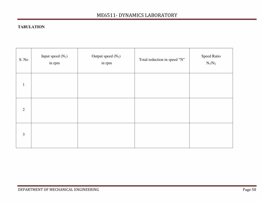
TABULATION
S. No Input speed (N1)
in rpm
Output speed (N2)
in rpm Total reduction in speed “N”
Speed Ratio
N1/N2
1
2
3

ME6511- DYNAMICS LABORATORY
DEPARTMENT OF MECHANICAL ENGINEERING Page 59
DIAGRAM
RESULT
Thus the speed ratio of an epicyclic gear reducer is carried out and the graph is plotted.

ME6511- DYNAMICS LABORATORY
DEPARTMENT OF MECHANICAL ENGINEERING Page 60
BALANCING OF RECIPROCATING MASSES
Ex. no: 15
Date:
AIM
To determine the balancing speed and maximum amplitude frequency of the reciprocating
masses
APPARATUS REQUIRED
1. Reciprocating pump
2. Weights
3. Steel rule
FORMULA
1. Angular velocity (U)
U = 2XK60 <;A/>@8
2. Frequency of amplitude (f)
N = 12X �P
�
PROCEDURE
1. Fix the unbalanced masses as per the given conditions, radius, angular position and plane of
masses
2. Find out the balancing masses and angular positions using force polygon and couple polygon
3. Fix the balancing masses (calculated masses) at the respective radii and angular position
4. Run the system at certain speeds and check that the balancing is done effectively
5. If the rotor system rotates smoothly, without considerable vibrations means the system is
dynamically balanced.

ME6511
DEPARTMENT OF MECHANICAL ENGINEERING
DIAGRAM
ME6511- DYNAMICS LABORATORY
F MECHANICAL ENGINEERING Page 61

ME6511- DYNAMICS LABORATORY
DEPARTMENT OF MECHANICAL ENGINEERING Page 62
TABULATION
S. No Crank speed
(N) in rpm
Mass (kg)
Angular velocity
(U)
In rad/sec
Maximum
amplitude
(m)
Frequency of
amplitude
Fn
(Hz) m1 m2 B = m1+ m2
1
2
3

ME6511- DYNAMICS LABORATORY
DEPARTMENT OF MECHANICAL ENGINEERING Page 63
RESULT
The given reciprocating system has been dynamically balanced.

ME6511- DYNAMICS LABORATORY
DEPARTMENT OF MECHANICAL ENGINEERING Page 64
BALANCING OF ROTATING MASSES
Ex. no: 16
Date:
AIM
To balance the given rotor system dynamically with the aid of the force polygon and the couple
polygon
APPARATUS REQUIRED
- Rotor system
- Weight
- Steel rule
FORMULA
1. Centrifugal force = m × r (N)
2. Couple = m × r × l (Nm)
PROCEDURE
1. Fix the unbalanced masses as per the given conditions, radius, angular position and plane of
masses
2. Find out the balancing masses and angular positions using force polygon and couple polygon
3. Fix the balancing masses (calculated masses) at the respective radii and angular position
4. Run the system at certain speeds and check that the balancing is done effectively
5. If the rotor system rotates smoothly, without considerable vibrations means the system is
dynamically balanced.
DIAGRAM
1. Plane of mass
2. Angular position of the masses
3. Force polygon

ME6511- DYNAMICS LABORATORY
DEPARTMENT OF MECHANICAL ENGINEERING Page 65
TABULATION
S. No Planes of mass
Mass
‘m’
Kg
Radius
‘r’
m
Centrifugal force
N
Distance from reference plane
‘l’ (m) Couple

ME6511
DEPARTMENT OF MECHANICAL ENGINEERING
DIAGRAM
ME6511- DYNAMICS LABORATORY
F MECHANICAL ENGINEERING
Angular position of the masses
Plane of mass
Page 66

ME6511
DEPARTMENT OF MECHANICAL ENGINEERING
RESULT
The given rotor system has been dynamically balanced with the aid of force polygon and
couple polygon.
ME6511- DYNAMICS LABORATORY
F MECHANICAL ENGINEERING
Force polygon
Couple polygon
The given rotor system has been dynamically balanced with the aid of force polygon and
Page 67
The given rotor system has been dynamically balanced with the aid of force polygon and

ME6511- DYNAMICS LABORATORY
DEPARTMENT OF MECHANICAL ENGINEERING Page 68
STUDY THE PROFILE AND JUMP PHENOMENON OF CAM
Ex. no: 17
Date:
AIM
To study the profile of given cam using cam analysis system and to draw the displacement
diagram for the follower and the cam profile. Also to study the jump speed characteristics of the cam
follower mechanism
APPARATUS REQUIRED
Cam analysis system & dial gauge
DESCRIPTION
A cam is a machine element such as a cylinder or any other solid with surface of contact so
designed as to give a predetermined motion to another element called the follower. A cam is a rotating
body importing oscillating motor to the follower. All cam mechanisms are composed of at least there
links viz.
1. Cam
2. Follower
3. Frame which guides follower cam
GRAPH
Displacement diagram and also the cam profile is drawn using a polar graph chart. The
velocity vs acceleration curve is drawn.
PROCEDURE
Cam analysis system consists of cam roller, follower, pull load and guide of pull rod.
1. Set the cam at 00 and note down the projected length of the pull rod.
2. Rotate the cam through 100 and note down the projected length of the pull rod above the guide
3. Note down the corresponding displacement of the follower
JUMP SPEED
1. The cam is run at gradually increasing speeds, and the speed at which the follower jumps off is
observed
2. This jump speed is observed for different loads on the follower.

ME6511- DYNAMICS LABORATORY
DEPARTMENT OF MECHANICAL ENGINEERING Page 69
DIAGRAM
Cam and follower

ME6511- DYNAMICS LABORATORY
DEPARTMENT OF MECHANICAL ENGINEERING Page 70
TABULATION
S. No Description
Forward stroke
Dwell
Return stroke
Dwell
Start End Start End
1 Angle in degree
2 Followed lift in ‘mm’

ME6511- DYNAMICS LABORATORY
DEPARTMENT OF MECHANICAL ENGINEERING Page 71
RESULT
Thus the profile of cam is drawn and the jump phenomenon is studied.

ME6511- DYNAMICS LABORATORY
DEPARTMENT OF MECHANICAL ENGINEERING Page 72
SINGLE ROTOR SYSTEM
Ex. no: 18
Date:
AIM
To determine the natural frequency of a steel shaft by applying free torsional vibration in a
single rotor system
APPARATUS REQUIRED
- Shaft
- Rotor
- Stop watch
FORMULA USED
1. Natural frequency
�� = ��.�� ���F��GHF��LFI� HGJ�� . Hz
2. Polar moment of inertia of shaft
$ = �'(0� m
4
3. Torsional stiffness of a shaft for flywheel length (l)
x� = `×2�5 : x� = `×2
�.
Where,
C = Rigidity of shaft modulus = 84*109 N/m
2
4. Total torsional stiffness
x = x� + x�. N/m
5. Mass moment of flywheel of rotor, I = mK2
K = radius of gyration = 0.5 m
6. Natural frequency of torsional vibration
�� = ��� �y
2 . Hz
PROCEDURE
ME6511- DYNAMICS LABORATORY
DEPARTMENT OF MECHANICAL ENGINEERING Page 73
1. The given shaft is fixed as both ends
2. A rotor of known mass is attached to the center of shaft
3. The rotor is allowed to vibration for the particular number of oscillation in the time taken is
noted down
4. Experiment is repeated for vice versa of readings
5. Thus the natural frequency of single rotor system can be calculated.

ME6511- DYNAMICS LABORATORY
DEPARTMENT OF MECHANICAL ENGINEERING Page 74
TABULATION
S. No
Experimental value Theoretical value of stiffness (N/m)
Natural
frequency
(Fn) Hz
Torsional
stiffness
(q) N/m No of oscillation
(n)
Time taken for n
oscillation
(sec)
Natural
frequency
(Hz)
Torsional
stiffness for
length (q1)
Torsional
stiffness for
length (q2)
1
2
3
ME6511- DYNAMICS LABORATORY
DEPARTMENT OF MECHANICAL ENGINEERING Page 75
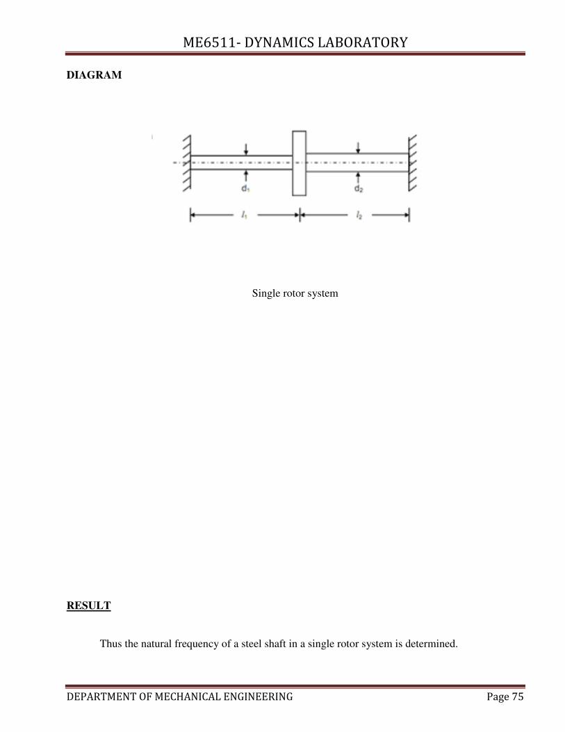
DIAGRAM
Single rotor system
RESULT
Thus the natural frequency of a steel shaft in a single rotor system is determined.