Embed Size (px)
Citation preview

“ME36”“ME36”SCOMPARTI MODULARI DI MEDIA TENSIONE CON INVOLUCRO METALLICO
EQUIPAGGIATI CON IMS ISOLATO IN SF6SCOMPARTI MODULARI DI MEDIA TENSIONE CON INVOLUCRO METALLICO
EQUIPAGGIATI CON IMS ISOLATO IN SF6
MV METALENCLOSED MODULAR PANELS EQUIPPED WITH SF6 SWITCH DISCONNECTORS
MV METALENCLOSED MODULAR PANELS EQUIPPED WITH SF6 SWITCH DISCONNECTORS
36kV – 630A – 16kA36kV – 630A – 16kA

22 \ 2522 \ 25
1
5
6
7
8
9
10
12
14
19
24
27
29
Caratteristiche generali
Tipologie standard
- Scomparto arrivo e risalita sbarre “R7”
- Scomparto arrivo/partenza consezionatore di terra “LT7”
- Scomparto arrivo/partenza con IMS “L7”
- Scomparto protezione trasformatore “F7”
- Scomparto misure “ARSM”
-Scomparto protezione generale coninterruttore in SF6/Vuoto “PG”
Caratteristiche dei componenti
- Interruttore di manovra-sezionatore SD36/L
- Interruttore di manovra-sezionatore con fusibili SD36/F
- Sezionatore D36
- Sezionatore di terra ES033
Tipologie di comandi
General characteristics
Standard types
- Incoming and bus riser unit “R7”
- Incoming/outgoing with earthing switch “LT7”
- Incoming/outgoing with switchdisconnector “L7”
- Transformer protection unit “F7”
- Measurement unit “ARSM”
- General protection unit “PG” withSF6/Vacuum circuit-breaker
Characteristics of components
- Switch-disconnector type SD36/L
- Switch-disconnector type SD36/F equipped with fuses
- Disconnector type D36
- Earthing switch type ES033
Operation mechanism types
1
5
6
7
8
9
10
12
14
19
24
27
29
22 \ 25
INDICE pag. INDEX page
EA s.r.l. si riserva il diritto di apportare, in qualsiasi momento,eventuali modifiche per motivi di carattere tecnico o commerciale;pertanto i dati e le illustrazioni contenute in questa pubblicazione sonoaggiornate fino al momento dell’approvazione di stampa
EA s.r.l. reserves the right to carry out, without any prior notice, anymodifications it deems necessary in order to improve and meet anyconstruction requirement. Therefore, the data and illustrations in thispublication are updated up to the point of approval for printing.
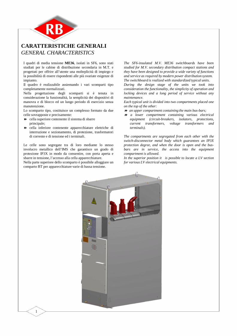
I quadri di media tensione ME36, isolati in SF6, sono statistudiati per le cabine di distribuzione secondaria in M.T. eprogettati per offrire all’utente una molteplicità di impiego ela possibilità di essere rispondenti alle più svariate esigenze diimpianto.Il quadro è realizzabile assiemando i vari scomparti tipocompletamente normalizzati.Nella progettazione degli scomparti si è tenuta inconsiderazione la funzionalità, la semplicità dei dispositivi dimanovra e di blocco ed un lungo periodo di esercizio senzamanutenzione.Lo scomparto tipo, costituisce un complesso formato da duecelle sovrapposte e precisamente: cella superiore contenente il sistema di sbarre
principale; cella inferiore contenente apparecchiature elettriche di
interruzione e sezionamento, di protezione, trasformatoridi corrente e di tensione ed i terminali.
Le celle sono segregate tra di loro mediante lo stessoinvolucro metallico dell’IMS che garantisce un grado diprotezione IP3X in modo da consentire, con porta aperta esbarre in tensione, l’accesso alla cella apparecchiature.Nella parte superiore dello scomparto è possibile alloggiare uncomparto BT per apparecchiature varie di bassa tensione.
The SF6-insulated M.V. ME36 switchboards have beenstudied for M.V. secondary distribution compact stations andthey have been designed to provide a wide variety of functionsand service as required by modern power distribution system.The switchboard is realized with standardized typical units.During the design stage of the units we took intoconsideration the functionality, the simplicity of operation andlocking devices and a long period of service without anymaintenance.Each typical unit is divided into two compartments placed oneon the top of the other: an upper compartment containing the main bus-bars; a lower compartment containing various electrical
equipment (circuit-breakers, isolators, protections,current transformers, voltage transformers andterminals).
The compartments are segregated from each other with theswitch-disconnector metal body which guarantees an IP3Xprotection degree, and when the door is open and the bus-bars are in service, the access into the equipmentcompartment is allowed.In the superior position it is possible to locate a LV sectionfor various LV electrical equipments.
CARATTERISTICHE GENERALIGENERAL CHARACTERISTICS

I quadri ME36 presentano le seguenti caratteristiche:A) Massima sicurezza per il personale ottenuta con: Messa a terra di tutta la struttura del quadro e della
segregazione metallica tra le celle; Interblocchi meccanici che garantiscono l’esatta
sequenza delle manovre; Grado di protezione IP3X sull’involucro esterno; A richiesta tenuta all’arco interno 16 kA – 1”.B) Sicurezza contro gli incendi:La segregazione metallica tra le celle e l’utilizzo di materialiisolanti autoestinguenti impediscono il diffondersi di eventualiincendi.C) Facile manovrabilità:Tutte le manovre di comando si effettuano dal fronte a mezzodi dispositivi semplici e funzionali, con segnalazionimeccaniche della posizione dei vari componenti.Chiare istruzioni per le manovre sono riportate sul fronte delquadro.D) VersatilitàDisponibilità di esecuzione per vari schemi di impianti.Larghezza frontale 700 – 1100 mm (tenuta all’arco interno arichiesta).E) Accurata scelta di materiali e quindi lunga durata di
funzionamento: Il colore standard è grigio RAL 7035. Altri colori a
richiesta.
The main aspects of ME36 switchboards are as following:A) Maximum safety for personnel thanks to: Earthing of both the whole switchboard structure and
the metal division between the compartments; Mechanical interlocks which assure the exact
operation sequence; IP3X protection degree on the external housing; Internal arc proofed 16 kA – 1” (on request).B) Protection against the spread of fire:The metal segregation of the compartments and the use ofself-extinguishing insulating materials prevent the spreadingof fire.C) Easy operation:All the various operations are carried out from the front of theswitchboard by means of simple and functional devices,provided with mechanical signals indicating the position ofthe components.Clear operation instructions on the front of the switchboard.D) VersatilityAll different technical applications.Esecution width 700 - 1100 mm (Internal arc tested onrequest).E) Long functional life throught careful choice of
materials: Standard colour: grey RAL 7035 (other colours on
request).
FEATURES AND APPLICATION RANGESThe ME36 swicthboard is made of a modular units(Switchboards) with SD36 Switch-disconnectorcompletely SF6 insulated.It’s possible to use standard cable glands (indoor use).The most important application ranges of the ME36switchboards are the following: public secondary distribution industrial distribution
SWITCH-DISCONNECTOR FEATURESThe SD36 swicth-disconnector is compact type and lowvolume of SF6 insulation.The metallic body makes the segregation betweenterminal cable box and busbar with high safe degree.Inside there is an earthing switch with making capacity.The operating mechanism is very reliable and it ispossible to have hand or motorized system.
CARATTERISTICHE E CAMPI DI IMPIEGOIl quadro ME36 è costituito da unità modulari(Scomparti) con IMS tipo SD36 completamente isolatoin SF6.Possono essere impiegate terminazioni di cavo standardper uso interno.I campi di impiego dei quadri ME36 sonofondamentalmente i seguenti: distribuzione secondaria pubblica distribuzione industriale
CARATTERISTICHE DELL’IMSL’interruttore di manovra-sezionatore SD36 è di tipocompatto con isolamento a basso volume in SF6.L’involucro metallico esterno funge da segregazione travano terminali e sbarre con elevato grado di sicurezza.All’interno è posizionato un sezionatore di terra conpotere di chiusura.Il comando è particolarmente affidabile e può essere siamanuale che motorizzato.
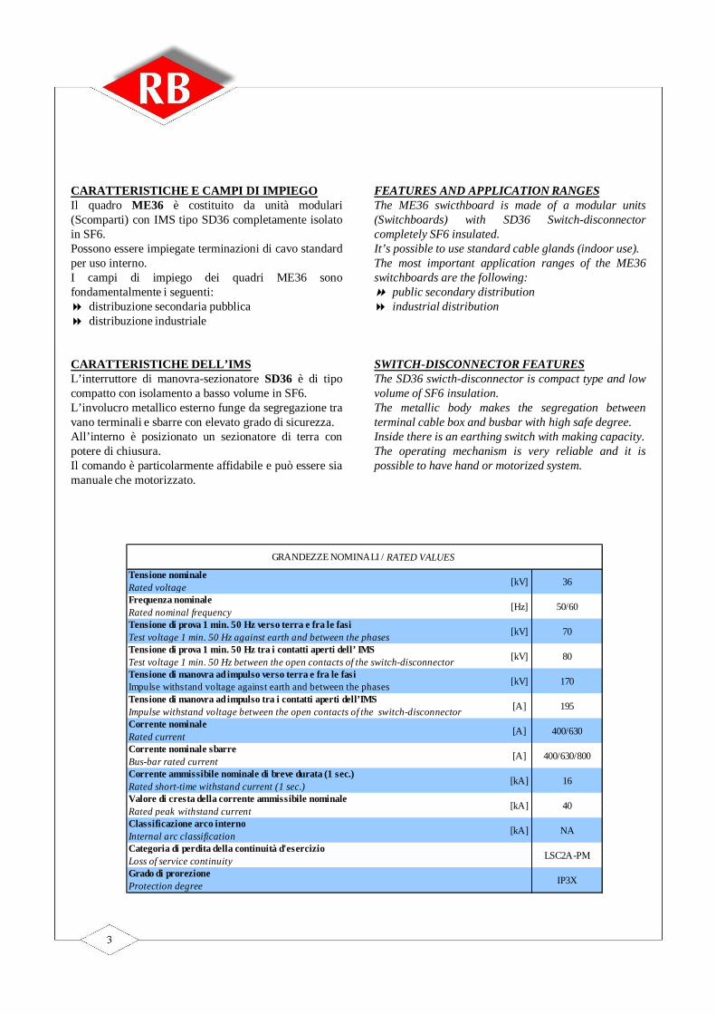
Tensione nominaleRated voltageFrequenza nominaleRated nominal frequencyTensione di prova 1 min. 50 Hz verso terra e fra le fasiTest voltage 1 min. 50 Hz against earth and between the phasesTensione di prova 1 min. 50 Hz tra i contatti aperti dell’ IMSTest voltage 1 min. 50 Hz between the open contacts of the switch-disconnectorTensione di manovra ad impulso verso terra e fra le fasiImpulse withstand voltage against earth and between the phasesTensione di manovra ad impulso tra i contatti aperti dell’IMSImpulse withstand voltage between the open contacts of the switch-disconnectorCorrente nominaleRated currentCorrente nominale sbarreBus-bar rated currentCorrente ammissibile nominale di breve durata (1 sec.)Rated short-time withstand current (1 sec.)Valore di cresta della corrente ammissibile nominaleRated peak withstand currentClassificazione arco internoInternal arc classificationCategoria di perdita della continuità d'esercizioLoss of service continuityGrado di prorezioneProtection degree
[kV]
[kV]
50/60
[kA]
[kA]
[A]
[A]
[kA]
[A]
36
170
[Hz]
70
[kV]
[kV]
GRANDEZZE NOMINALI / RATED VALUES
IP3X
40
LSC2A-PM
NA
400/630/800
16
195
400/630
80
Due to the continuous development of Standardsas well as of materials, the characteristics anddimensions indicated in this catalogue must beregarded as binding only on our confirmation.
Per tener conto dell’evoluzione sia delle normesia dei materiali, le caratteristiche e ledimensioni di ingombro indicate nel presentecatalogo si potranno ritenere impegnative solodopo conferma da parte nostra.
QUALITY SYSTEMThe designing and manufacturing system iscarried out with a rigid application of theCompany Quality System, certified by CSQ(EQNET Member), in compliance with ISO9001-2000 Standards.
SISTEMA QUALITA’Il ns. sistema progettuale e produttivo vieneeffettuato sotto la rigida applicazione di unSistema Qualità aziendale certificato dal CSQ(EQNET Member) secondo la normativa ISO9001-2000
TEST REPORTSME36 cubicles have successfully passed all thetype tests requested by the internationalStandards in officially acknowledged testinglaboratories.
International StandardsIEC 62271-200, IEC60694, IEC 60529,IEC 60265-1, 61271-102
Other StandardsItalian CEI EN 62271-200 Standards Italian accident prevention law (D.P.R. 547)
RAPPORTI DI PROVAGli scomparti della serie ME36 hannopositivamente superato in laboratori ufficialitutte le prove di tipo in accordo alle Normeinternazionali.
Norme Internazionali IEC 62271-200, IEC 60694, IEC 60529,IEC 60265-1, 61271-102.
Altre NormeNorme Italiane CEI EN 62271-200 Antinfortunistiche Italiane (D.P.R. 547)
ENVIROMENTThe Quality System is integrated with anEnviromental policy that is of primaryimportance for our company.Enviromental Management Systems is certified byCSQ ( EQNET member) in compliance with ISO14001-2004 standard.
AMBIENTEIl Sistema Qualità è integrato con una politicaambientale che riveste un ruolo fondamentaleall’interno dell’EA s.r.l..Il sistema di Gestione Ambientale è certificato dalCSQ (EQNET member) secondo la normativaISO 14001-2004.
SERIE ME36ME36 SERIES
RIFERIMENTI A NORMATIVE STANDARDS

TIPOLOGIE STANDARDSTANDARD TYPES
INCOMING AND BUS RISER UNIT “R7”
SCOMPARTO ARRIVO E RISALITA SBARRE “R7” SCOMPARTO ARRIVO / PARTENZA CON SEZIONATORE DI TERRA “LT7”
INCOMING/OUTCOMING WITH EARTHING SWITCH “LT7”
SCOMPARTO PROTEZIONE GENERALE “PG” CON INTERRUTTORE IN SF6 / VUOTO
GENERAL PROTECTION UNIT “PG”WITH SF6 / VACUUM CIRCUIT-BREAKER
SCOMPARTO ARRIVO / PARTENZA CON IMS “L7”
INCOMING / OUTCOMING WITH SWITCH-DISCONNECTOR “L7”
SCOMPARTO PROTEZIONE TRASFORMATORE “F7”
TRANSFORMER PROTECTION “F7”
SCOMPARTO MISURE “ARSM”
MEASUREMENT UNIT“ARSM”
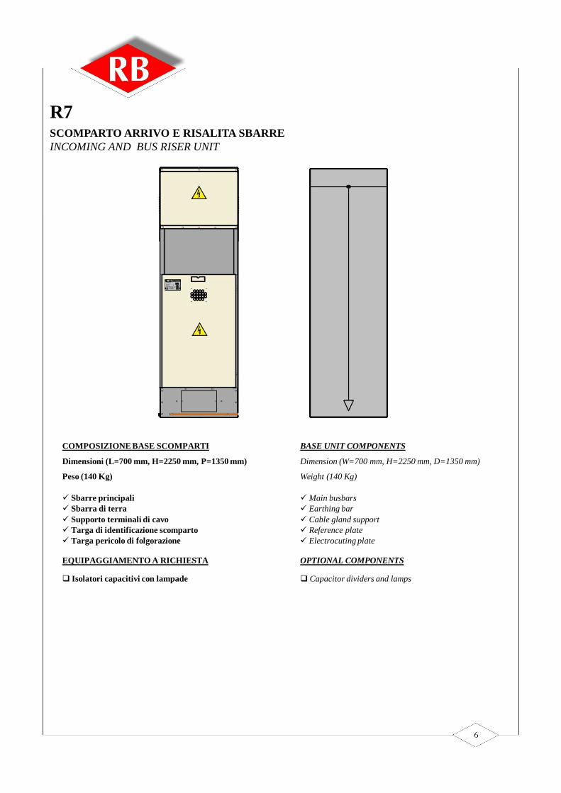
SCOMPARTO ARRIVO E RISALITA SBARREINCOMING AND BUS RISER UNIT
R7
COMPOSIZIONE BASE SCOMPARTI
Dimensioni (L=700 mm, H=2250 mm, P=1350 mm)
Peso (140 Kg)
Sbarre principali Sbarra di terra Supporto terminali di cavo Targa di identificazione scomparto Targa pericolo di folgorazione
EQUIPAGGIAMENTO A RICHIESTA
Isolatori capacitivi con lampade
BASE UNIT COMPONENTS
Dimension (W=700 mm, H=2250 mm, D=1350 mm)
Weight (140 Kg)
Main busbars Earthing bar Cable gland support Reference plate Electrocuting plate
OPTIONAL COMPONENTS
Capacitor dividers and lamps

SCOMPARTO ARRIVO / PARTENZA CON SEZIONATORE DI TERRA INCOMING / OUTCOMING WITH EARTHING SWITCH
LT7
COMPOSIZIONE BASE SCOMPARTI
Dimensioni (L=700 mm, H=2250 mm, P=1350 mm)
Peso (140 Kg)
Sbarre principali Sbarra di terra Sezionatore di terra Interblocchi meccanici Schema sinottico Supporto terminali di cavo Targa di identificazione scomparto Targa pericolo di folgorazione
EQUIPAGIAMENTO A RICHIESTA
Isolatori capacitivi con lampade Blocchi a chiave Illuminazione interna
BASE UNIT COMPONENTS
Dimension (W=700 mm, H=2250 mm, D=1350 mm)
Weight (140 Kg)
Main busbars Earthing bar Earthing switch Safety interlocks Synoptic diagram Cable gland support Reference plate Electrocuting plate
OPTIONAL COMPONENTS
Capacitor dividers and lamps Key interlocks Internal lighting for unit
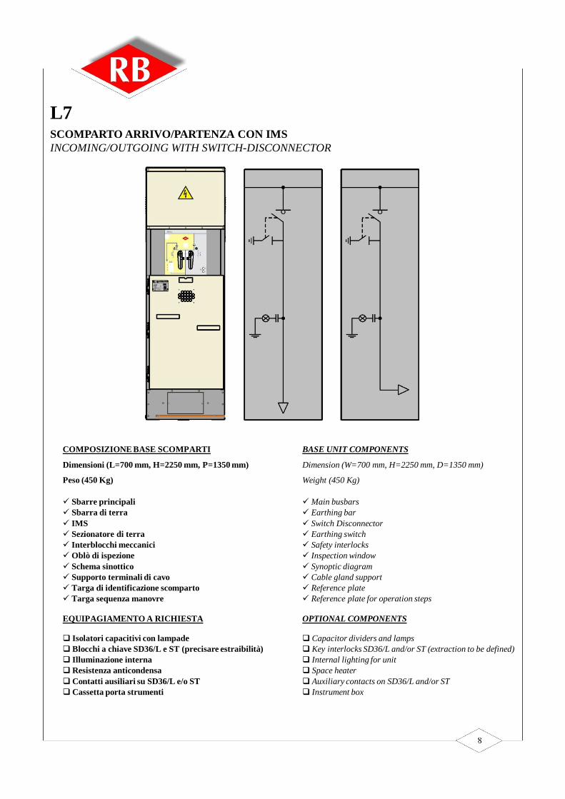
SCOMPARTO ARRIVO/PARTENZA CON IMS INCOMING/OUTGOING WITH SWITCH-DISCONNECTOR
L7
COMPOSIZIONE BASE SCOMPARTI
Dimensioni (L=700 mm, H=2250 mm, P=1350 mm)
Peso (450 Kg)
Sbarre principali Sbarra di terra IMS Sezionatore di terra Interblocchi meccanici Oblò di ispezione Schema sinottico Supporto terminali di cavo Targa di identificazione scomparto Targa sequenza manovre
EQUIPAGIAMENTO A RICHIESTA
Isolatori capacitivi con lampade Blocchi a chiave SD36/L e ST (precisare estraibilità) Illuminazione internaResistenza anticondensa Contatti ausiliari su SD36/L e/o STCassetta porta strumenti
BASE UNIT COMPONENTS
Dimension (W=700 mm, H=2250 mm, D=1350 mm)
Weight (450 Kg)
Main busbars Earthing bar Switch Disconnector Earthing switch Safety interlocks Inspection window Synoptic diagram Cable gland support Reference plate Reference plate for operation steps
OPTIONAL COMPONENTS
Capacitor dividers and lamps Key interlocks SD36/L and/or ST (extraction to be defined) Internal lighting for unit Space heater Auxiliary contacts on SD36/L and/or ST Instrument box

SCOMPARTO PROTEZIONE TRASFORMATORETRANSFORMER PROTECTION UNIT
F7
COMPOSIZIONE BASE SCOMPARTI
Dimensioni (L=700 mm, H=2250 mm, P=1350 mm)
Peso (475 Kg)
Sbarre principali Sbarra di terra IMS Sezionatore di terra Interblocchi meccanici Oblò di ispezione Schema sinottico Targa di identificazione scomparto Targa sequenza manovre
EQUIPAGIAMENTO A RICHIESTA
Isolatori capacitivi con lampade Blocchi a chiave SD36/L e ST (precisare estraibilità) Illuminazione internaResistenza anticondensa Contatti ausiliari su SD36/L e/o STCassetta porta strumenti Fusibili MT Bobina di apertura (220 Vca - 110/48/24 Vcc)
BASE UNIT COMPONENTS
Dimension (W=700 mm, H=2250 mm, D=1350 mm)
Weight (475 Kg)
Main busbars Earthing bar Switch Disconnector Earthing switch Safety interlocks Inspection window Synoptic diagram Reference plate Reference plate for operation steps
OPTIONAL COMPONENTS
Capacitor dividers and lamps Key interlocks SD36/L and/or ST (extraction to be defined) Internal lighting for unit Space heater Auxiliary contacts on SD36/L and/or ST Instrument boxMV fusesOpening coil (220 Vca – 110/48/24 Vdc)

SCOMPARTO MISUREMEASUREMENT UNIT
ARSM
COMPOSIZIONE BASE SCOMPARTI
Dimensioni (L=700 mm, H=2250 mm, P=1350 mm)
Peso (150 Kg esclusa TA e TV)
Sbarre principali Sbarra di terra Oblò di ispezione Schema sinottico Targa di identificazione scomparto Targa pericolo di folgorazione
EQUIPAGIAMENTO A RICHIESTA
Isolatori capacitivi con lampadeCassetta porta strumenti Trasformatori di tensione Trasformatori di corrente
BASE UNIT COMPONENTS
Dimension (W=700 mm, H=2250 mm, D=1350 mm)
Weight (150 Kg CT’s and VT’s not included)
Main busbars Earthing bar Inspection window Synoptic diagram Reference plate Electrocutioning plate
OPTIONAL COMPONENTS
Capacitor dividers and lamps Instrument box Voltage transformers Current transformers
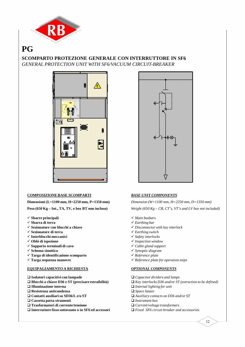
SCOMPARTO PROTEZIONE GENERALE CON INTERRUTTORE IN SF6 GENERAL PROTECTION UNIT WITH SF6/VACUUM CIRCUIT-BREAKER
PG
COMPOSIZIONE BASE SCOMPARTI
Dimensioni (L=1100 mm, H=2250 mm, P=1350 mm)
Peso (650 Kg – Int., TA, TV, e box BT non incluso)
Sbarre principali Sbarra di terra Sezionatore con blocchi a chiave Sezionatore di terra Interblocchi meccanici Oblò di ispezione Supporto terminali di cavo Schema sinottico Targa di identificazione scomparto Targa sequenza manovre
EQUIPAGIAMENTO A RICHIESTA
Isolatori capacitivi con lampade Blocchi a chiave D36 e ST (precisare estraibilità) Illuminazione internaResistenza anticondensa Contatti ausiliari su SD36/L e/o STCassetta porta strumenti Trasformatori di corrente/tensione Interruttore fisso sottovuoto o in SF6 ed accessori
BASE UNIT COMPONENTS
Dimension (W=1100 mm, H=2250 mm, D=1350 mm)
Weight (650 Kg – CB, CT’s, VT’s and LV box not included)
Main busbars Earthing bar Disconnector with key interlock Earthing switch Safety interlocks Inspection window Cable gland support Synoptic diagram Reference plate Reference plate for operation steps
OPTIONAL COMPONENTS
Capacitor dividers and lamps Key interlocks D36 and/or ST (extraction to be defined) Internal lighting for unit Space heater Auxiliary contacts on D36 and/or ST Instrument box Current/voltage transformers Fixed SF6 circuit breaker and accessories
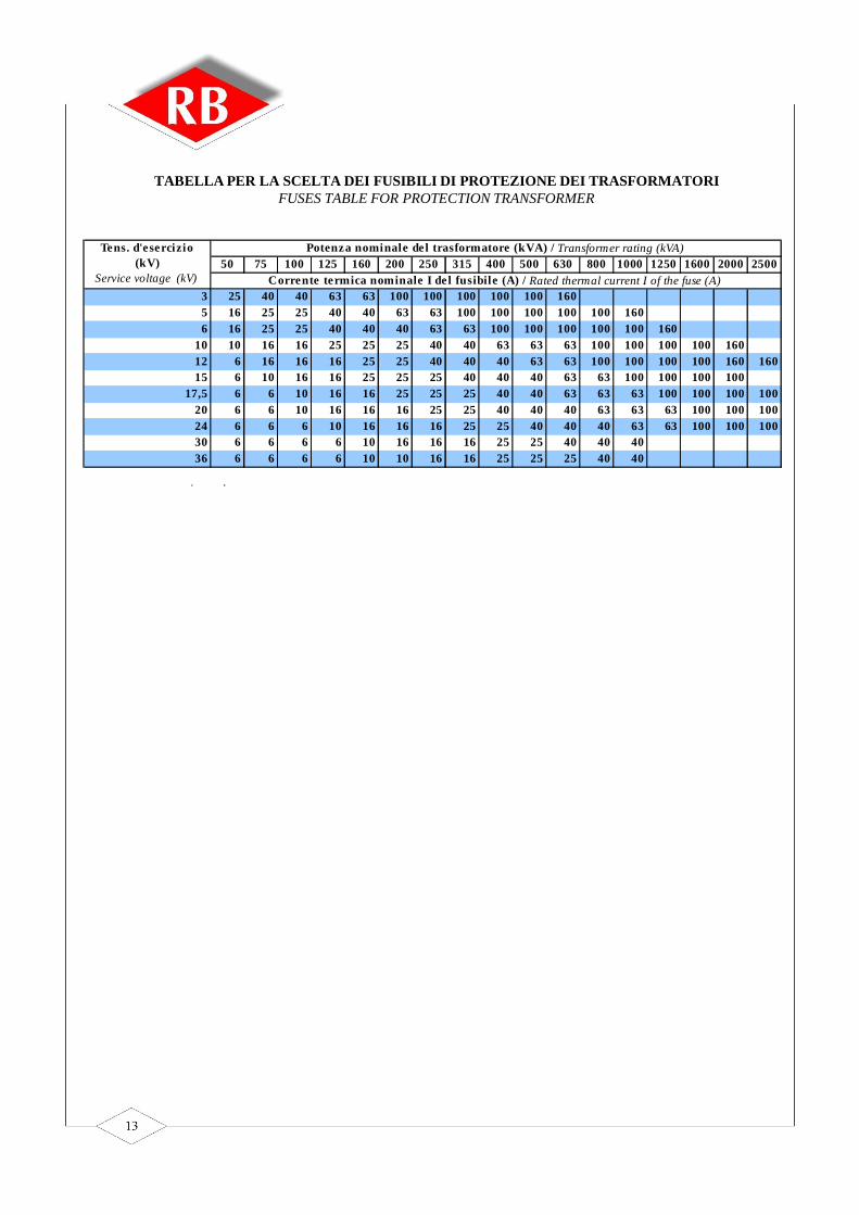
TABELLA PER LA SCELTA DEI FUSIBILI DI PROTEZIONE DEI TRASFORMATORIFUSES TABLE FOR PROTECTION TRANSFORMER
50 75 100 125 160 200 250 315 400 500 630 800 1000 1250 1600 2000 2500
3 25 40 40 63 63 100 100 100 100 100 1605 16 25 25 40 40 63 63 100 100 100 100 100 1606 16 25 25 40 40 40 63 63 100 100 100 100 100 160
10 10 16 16 25 25 25 40 40 63 63 63 100 100 100 100 16012 6 16 16 16 25 25 40 40 40 63 63 100 100 100 100 160 16015 6 10 16 16 25 25 25 40 40 40 63 63 100 100 100 100
17,5 6 6 10 16 16 25 25 25 40 40 63 63 63 100 100 100 10020 6 6 10 16 16 16 25 25 40 40 40 63 63 63 100 100 10024 6 6 6 10 16 16 16 25 25 40 40 40 63 63 100 100 10030 6 6 6 6 10 16 16 16 25 25 40 40 4036 6 6 6 6 10 10 16 16 25 25 25 40 40
Tens. d'esercizio (kV)
Service voltage (kV)
Potenza nominale del trasformatore (kVA) / Transformer rating (kVA)
Corrente termica nominale I de l fusibile (A) / Rated thermal current I of the fuse (A)
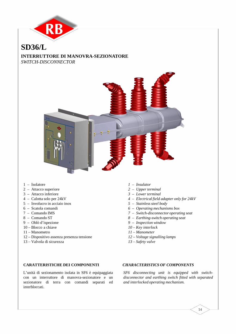
CARATTERISTICHE DEI COMPONENTI
L’unità di sezionamento isolata in SF6 è equipaggiatacon un interruttore di manovra-sezionatore e unsezionatore di terra con comandi separati edinterbloccati.
SF6 disconnecting unit is equipped with switch-disconnector and earthing switch fitted with separatedand interlocked operating mechanism.
CHARACTERISTICS OF COMPONENTS
INTERRUTTORE DI MANOVRA-SEZIONATORESWITCH-DISCONNECTOR
SD36/L
1 – Isolatore2 – Attacco superiore3 – Attacco inferiore4 – Calotta solo per 24kV5 – Involucro in acciaio inox6 – Scatola comandi7 – Comando IMS8 – Comando ST9 – Oblò d’ispezione10 – Blocco a chiave11 – Manometro12 – Dispositivo assenza presenza tensione13 – Valvola di sicurezza
1 – Insulator2 – Upper terminal3 – Lower terminal4 – Electrical field adapter only for 24kV5 – Stainless steel body6 – Operating mechanisms box7 – Switch-disconnector operating seat8 – Earthing-switch operating seat9 – Inspection window10 – Key interlock11 – Manometer12 – Voltage signalling lamps13 – Safety valve

SD36/LCARATTERISTICHE TECNICHETECHNICAL FEATURES
Tensione nominaleRated nominal voltageFrequenza nominaleRated nominal frequencyTensione di prova 1 min. 50 Hz verso terra e fra le fasiTest voltage 1 min. 50 Hz against earth and between the phasesTensione di prova 1 min. 50 Hz tra i contatti aperti del l’ IMSTest voltage 1 min. 50 Hz between the switch-disconnector opened contactsTensione di manovra ad impulso verso terra e fra le fasiImpulse withstand voltage against earth and between the phasesTensione di manovra ad impulso tra i contatti aperti del l’IMSImpulse withstand voltage between the switch-disconnector opened contactsCorrente nominaleRated nominal currentPotere di interruzione nominale carico prevalentemente attivoRated breaking capacity mainly active load Potere di interruzione nominale linee a vuotoRated breaking capacity no-load overhead lines Potere di interruzione nominale cavi a vuotoRated breaking capacity no-load cables Corrente ammissibile nominale di breve durata (1 sec.)Rated short-time withstand current (1 sec.)Valore di cresta del la corrente ammissibi le nominaleRated peak withstand currentPotere di stabi limento Making capacityGuasto a terraEarth fault currentCavo o l inea a vuoto in condiz ioni di guasto a terraCable and line charging current under earth faultsCiclo di omologazione secondo le norme IECIEC standard test cycle Numero di manovre meccanicheEndurance operation test (cycles)
GRANDEZZE NOMINALI / RATED VALUES
[kV] 36
[kV] 70
[Hz] 50/60
[kV] 170
[kV] 80
[A] 630
[kV] 195
[A] 25
[A] 630
[kA] 16
[A] 25
[kA] 40
[kA] 40
[A] 200
50[A]
M2
E3

SD36/LDIMENSIONI D’INGOMBRO E INSTALLAZIONEOVERALL AND INSTALLATION DIMENSIONS
RB
SD36/L
L1
L2
L3
K O K OK I K I
AA
I
O
I
OM
I
O
496 325 325 52
373
346
350 min.350
349.
534
9.5
146
136
250.
5
525
322
206 206
350 min.350
min
.335
147.
634
.4
148
175.
4
111
2
34
5
5
6
1 - Connessione cavo 2 - Connessione sbarra 3 - Interblocco sede di manovra ST 4 - Interblocco apertura porta
5 - Linea di sostegno IMS 6 - Punti di fissaggio IMS Ingombro dello scomparto
Connection bar
Earthing-switch opening seat interlock
Mechanical interlock between the earthing-switch and the door
Support switch-disconnector
Fixing points switch-disconnector
Overall dimension of the medium voltage box
Connection cable

SD36/LSCHEMA ELETTRICO 24Vcc - 48 VccWIRING DIAGRAM 24Vdc – 48 Vdc
Con
ness
ioni
a c
onne
ttore
14
poli
/ con
nect
ions
to 1
4 po
les c
onne
ctor
Con
ness
ioni
su
sche
da/ c
ard
conn
ectio
ns
Con
ness
ioni
mot
ore
/ mot
or co
nnec
tions
N.B
.:Sch
ema
rapp
rese
ntat
o ad
IMS
aper
to, t
erre
ape
rte
e as
senz
a di
alim
enta
zion
e au
silia
ria
/dia
gram
with
LBS
/ear
thin
g sw
itch
in o
pene
d po
sitio
n an
d no
t aux
iliar
y sup
ply

SD36/LSCHEMA ELETTRICO 110VccWIRING DIAGRAM 110Vdc
Con
ness
ioni
a c
onne
ttore
14
poli
/ con
nect
ions
to 1
4 po
les c
onne
ctor
Con
ness
ioni
gru
ppo
friz
ione
mot
ore
/ fri
ctio
n-m
otor
gro
up co
nnec
tions
N.B
.:Sch
ema
rapp
rese
ntat
o ad
IMS
aper
to, t
erre
ape
rte
e as
senz
a di
alim
enta
zion
e au
silia
ria
/dia
gram
with
LBS
/ear
thin
g sw
itch
in o
pene
d po
sitio
n an
d no
t aux
iliar
y sup
ply

CARATTERISTICHE DEI COMPONENTI
L’interruttore di manovra-sezionatore è strutturalmentesimile all’interruttore di manovra-sezionatore SD36/Lma è equipaggiato di base portafusibili e sistema diapertura attivato dal percussore dei fusibili esganciatore di apertura (opzione).SD36/F è equipaggiato con un interruttore di manovra-sezionatore e un sezionatore di terra con comandiseparati ed interbloccati.
Structurally, SD36/F is similar to SD36/L switch-disconnector but it is equipped with fuse-holder anddownstream fuses air insulated earthing switch andrelease system activated by fuse striker and shunt-tripcoil (optional).SD36/F is equipped with switch-disconnector andearthing switch fitted with separated and interlockedoperating mechanism.
CHARACTERISTICS OF COMPONENTS
INTERRUTTORE DI MANOVRA-SEZIONATORE CON FUSIBILI SWITCH-DISCONNECTOR EQUIPPED WITH FUSES
SD36/F

SD36/FCARATTERISTICHE TECNICHETECHNICAL FEATURES
Tensione nominaleRated nominal voltageFrequenza nominaleRated nominal frequencyTensione di prova 1 min. 50 Hz verso terra e fra le fasiTest voltage 1 min. 50 Hz against earth and between the phasesTensione di prova 1 min. 50 Hz tra i contatti aperti del l’ IMSTest voltage 1 min. 50 Hz between the switch-disconnector opened contactsTensione di manovra ad impulso verso terra e fra le fasiImpulse withstand voltage against earth and between the phasesTensione di manovra ad impulso tra i contatti aperti del l’IMSImpulse withstand voltage between the switch-disconnector opened contactsCorrente nominaleRated nominal currentPotere di interruzione nominale carico prevalentemente attivoRated breaking capacity mainly active load Potere di interruzione nominale linee a vuotoRated breaking capacity no-load overhead lines Potere di interruzione nominale cavi a vuotoRated breaking capacity no-load cables Corrente ammissibile nominale di breve durata (1 sec.)Rated short-time withstand current (1 sec.)Valore di cresta del la corrente ammissibi le nominaleRated peak withstand currentPotere di stabi limento Making capacityGuasto a terraEarth fault currentCavo o l inea a vuoto in condiz ioni di guasto a terraCable and line charging current under earth faultsCiclo di omologazione secondo le norme IECIEC standard test cycle Numero di manovre meccanicheEndurance operation test (cycles)
GRANDEZZE NOMINALI / RATED VALUES
[kV] 36
[kV] 70
[Hz] 50/60
[kV] 170
[kV] 80
[A] 630
[kV] 195
[A] 25
[A] 630
[kA] 16
[A] 25
[kA] 40
[kA] 40
[A] 200
50[A]
M2
E3
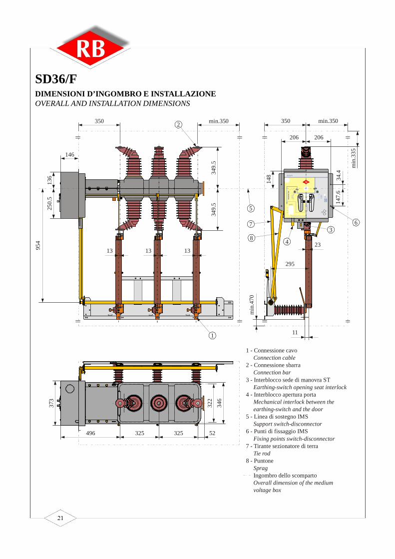
SD36/FDIMENSIONI D’INGOMBRO E INSTALLAZIONEOVERALL AND INSTALLATION DIMENSIONS
RB
SD36/F
L1
L2
L3
K O K OK I K I
AA
I
O
I
O
I
OM
373
496 325 325 52
346
322
350 min.350
349.
534
9.5
146
136
250.
5
954
13 13 13
206 206
350 min.350
min
.335
147.
634
.4
148
23
295
min
.470
11
1 - Connessione cavo 2 - Connessione sbarra 3 - Interblocco sede di manovra ST 4 - Interblocco apertura porta
5 - Linea di sostegno IMS 6 - Punti di fissaggio IMS 7 - Tirante sezionatore di terra 8 - Puntone Ingombro dello scomparto
Connection bar
Earthing-switch opening seat interlock
Mechanical interlock between the earthing-switch and the door
Support switch-disconnector
Fixing points switch-disconnector
Tie rod
Sprag
Overall dimension of the medium voltage box
Connection cable
1
2
3
4
5
67
8

SD36/FSCHEMA ELETTRICO 24Vcc - 48 VccWIRING DIAGRAM 24Vdc – 48 Vdc
Con
ness
ioni
a c
onne
ttore
14
poli
/ con
nect
ions
to 1
4 po
les c
onne
ctor
Con
ness
ioni
su
sche
da/ c
ard
conn
ectio
ns
Con
ness
ioni
mot
ore
/ mot
or co
nnec
tions
N.B
.:Sch
ema
rapp
rese
ntat
o ad
IMS
aper
to, t
erre
ape
rte
e as
senz
a di
alim
enta
zion
e au
silia
ria
/dia
gram
with
LBS
/ear
thin
g sw
itch
in o
pene
d po
sitio
n an
d no
t aux
iliar
y sup
ply

SD36/FSCHEMA ELETTRICO 110VccWIRING DIAGRAM 110Vdc
Con
ness
ioni
a c
onne
ttore
14
poli
/ con
nect
ions
to 1
4 po
les c
onne
ctor
Con
ness
ioni
gru
ppo
friz
ione
mot
ore
/ fri
ctio
n-m
otor
gro
up co
nnec
tions
N.B
.:Sch
ema
rapp
rese
ntat
o ad
IMS
aper
to, t
erre
ape
rte
e as
senz
a di
alim
enta
zion
e au
silia
ria
/dia
gram
with
LBS
/ear
thin
g sw
itch
in o
pene
d po
sitio
n an
d no
t aux
iliar
y sup
ply
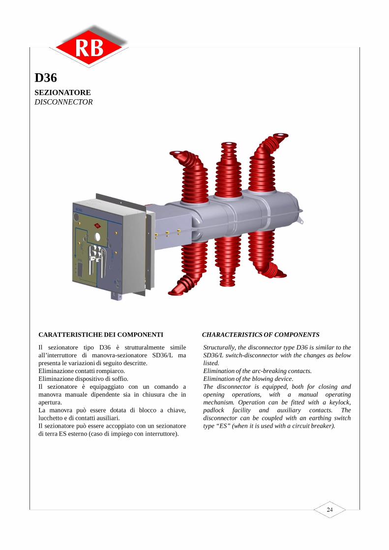
CARATTERISTICHE DEI COMPONENTI
Il sezionatore tipo D36 è strutturalmente simileall’interruttore di manovra-sezionatore SD36/L mapresenta le variazioni di seguito descritte.Eliminazione contatti rompiarco.Eliminazione dispositivo di soffio.Il sezionatore è equipaggiato con un comando amanovra manuale dipendente sia in chiusura che inapertura.La manovra può essere dotata di blocco a chiave,lucchetto e di contatti ausiliari.Il sezionatore può essere accoppiato con un sezionatoredi terra ES esterno (caso di impiego con interruttore).
Structurally, the disconnector type D36 is similar to theSD36/L switch-disconnector with the changes as belowlisted.Elimination of the arc-breaking contacts.Elimination of the blowing device.The disconnector is equipped, both for closing andopening operations, with a manual operatingmechanism. Operation can be fitted with a keylock,padlock facility and auxiliary contacts. Thedisconnector can be coupled with an earthing switchtype “ES” (when it is used with a circuit breaker).
CHARACTERISTICS OF COMPONENTS
SEZIONATORE DISCONNECTOR
D36

D36CARATTERISTICHE TECNICHETECHNICAL FEATURES
Tensione nominaleRated nominal voltageFrequenza nominaleRated nominal frequencyTensione di prova 1 min. 50 Hz verso terra e fra le fasiTest voltage 1 min. 50 Hz against earth and between the phasesTensione di prova 1 min. 50 Hz tra i contatti aperti del l’ IMSTest voltage 1 min. 50 Hz between the open contacts of the switch-disconnectorTensione di manovra ad impulso verso terra e fra le fasiImpulse withstand voltage against earth and between the phasesTensione di manovra ad impulso tra i contatti aperti del l’IMSImpulse withstand voltage between the open contacts of the switch-disconnectorCorrente nominaleRated nominal currentCorrente nominale sbarreBus-bar rated currentCorrente ammissibile nominale di breve durata (1 sec.)Rated short-time withstand current (1 sec.)Valore di cresta del la corrente ammissibi le nominaleRated peak withstand currentNumero di manovre meccanicheEndurance operation test (cycles)
40
M2
16
170
630
195
630
GRANDEZZE NOMINALI / RATED VALUES
36
70
80
50/60
[kV]
[Hz]
[kV]
[kV]
[kA]
[kA]
[kV]
[kV]
[A]
[A]

D36DIMENSIONI D’INGOMBRO E INSTALLAZIONEOVERALL AND INSTALLATION DIMENSIONS
RB
SD36/L
L1
L2
L3
K O K OK I K I
AA
I
O
I
OM
I
O
496 325 325 52
373
346
350 min.350
349.
534
9.5
146
136
250.
5
525
322
206 206
350 min.350
min
.335
147.
634
.4
148
175.
4
111
2
34
5
5
6
1 - Connessione cavo 2 - Connessione sbarra 3 - Interblocco sede di manovra ST 4 - Interblocco apertura porta
5 - Linea di sostegno SEZ 6 - Punti di fissaggio SEZ Ingombro dello scomparto
Connection bar
Earthing-switch opening seat interlock
Mechanical interlock between the earthing-switch and the door
Support disconnector
Fixing points disconnector
Overall dimension of the medium voltage box
Connection cable

CARATTERISTICHE DEI COMPONENTI
La manovra del sezionatore di terra avviene con uncomando indipendente sia in chiusura che in apertura.Il sezionatore può essere accoppiato con gli interruttoridi manovra-sezionatori e con i sezionatori.Il sezionatore di terra è completo di interbloccomeccanico reciproco tra porta e sezionatore di terra(accesso alla cella solo con sezionatore in posizione dichiuso ed impedimento della manovra del sezionatore aporta aperta).Il blocco può essere rimosso con apposito utensilegarantendo il grado di protezione IP2X.L’interblocco, una volta rimosso, ritorna nella suaposizione iniziale quando l’utensile viene tolto.Qualora venga rimosso il blocco non è possibilechiudere la porta se non dopo aver chiuso il sezionatoredi messa a terra.La manovra può essere dotata di blocco a chiave,lucchetto e di contatti ausiliari.Il sezionatore di terra è previsto per una corrente dibreve durata di 16 kA/1”.
Operation of the earthing switch takes place with ahand operating mechanism, both for closing andopening. The earthing switch can be coupled with othercomponents, such as switch-disconnectors anddisconnectors.The earthing switch is fitted with interlocks. Inparticular: mutual mechanical interlock between thedoor and the earthing switch which allows the door ofthe compartment to be opened only if the earthingswitch is closed. When the door is open it is not allowedto open the earthing switch.The lock can be deactivated by means of a special tool,which guarantees the IP2X protection degree.When the tool is removed , the lock returns on itsstarting position.When the lock is deactivated, the door can be closed
only if the earthing switch is closed.Operation can be fitted with a key lock, padlock facilityand auxiliary contacts. The earthing switches areplanned for a short-time current of 1 sec. equal to16 kA.
CHARACTERISTICS OF COMPONENTS
SEZIONATORE DI TERRA EARTHING SWITCH
ES033

ES033CARATTERISTICHE TECNICHETECHNICAL FEATURES
Tensione nominaleRated nominal voltageCorrente ammissibile nominale di breve durata (1 sec.)Rated short-time withstand current (1 sec.)Valore di cresta del la corrente ammissibi le nominaleRated peak withstand current
GRANDEZZE NOMINALI / RATED VALUES
[kV] 36
[kA] 16
[kA] 40

COMANDO IMS TIPO R
Le operazioni di apertura e chiusuraavvengono a velocità indipendentedall’operatore.Durante l’operazione di apertura e chiusurasi carica una molla che determina lamanovra rapida.Possibilità di comando motorizzato, contattiausiliari e blocchi a chiave.
COMANDO SEZIONATORE DI TERRA TIPO E
La manovra di chiusura è rapida ed avvienea velocità indipendente dall’operatoremediante energia accumulata nella molla.La manovra di apertura è lenta.Possibilità di contatti ausiliari e blocchi achiave.
COMANDO IMS – PROTEZIONE TRASFORMATORE CON FUSIBILI TIPO F
Le operazioni di apertura e chiusura,manuale o motorizzata, avvengono avelocità indipendente dall’operatore.Durante l’operazione di chiusura sicaricano contemporaneamente la molla dichiusura e la molla di apertura. Al terminedell’operazione di chiusura la molla diapertura rimane carica e permette unaoperazione rapida di apertura a mezzo disganciatore o per intervento del percussoredei fusibili.Possibilità di contatti ausiliari e blocchi achiave.
Switch-disconnector operating mechanismtype R
The speed of the closing and openingoperations is independant by the operator.During closing and opening operations aspring is charged and quick operations areallowed.Motor operating mechanism, auxiliarycontacts and key interlocks are available onrequest.
Earthing switch operating mechanism typeE
The speed of the closing operation isindependant by the operator.During closing operation a spring is chargedand quick operation is allowed. The speed ofopening operation is dependant by theoperator.Auxiliary contacts and key interlocks areavailable on request.
Switch-disconnector operating mechanismTransformer protection with fuses type F
The speed of the closing and openingoperations is independant by the operator.During closing operation opening andclosing springs are charged at the same time.When closed position is realized openingspring remains loaded and allows quickopening by means opening coil or fusestriker.Motor operating mechanism, auxiliarycontacts and key interlocks are available onrequest.
TIPOLOGIE DI COMANDIOPERATING MECHANISM TYPES

COMANDO IMS TIPO VR
Le manovre di chiusura e apertura sonolente e dipendono dall’operatore.Possibilità di contatti ausiliari e blocchi achiave.
COMANDO SEZIONATORE DI TERRA TIPO VE
Le manovre di chiusura e apertura sonolente e dipendono dall’operatore.Possibilità di contatti ausiliari e blocchi achiave.
Switch-disconnector operating mechanismtype VR
The speed of opening and closing operationis dependant by the operator.Auxiliary contacts and key interlocks areavailable on request.
Earthing switch operating mechanism typeVE
The speed of opening and closing operationis dependant by the operator.Auxiliary contacts and key interlocks areavailable on request.
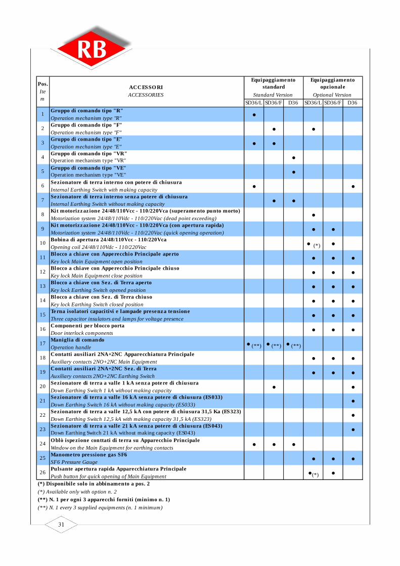
SD36/L SD36/F D36 SD36/L SD36/F D36
1 Gruppo di comando tipo "R" Operation mechanism type "R" •
2 Gruppo di comando tipo "F" Operation mechanism type "F" • •
3 Gruppo di comando tipo "E" Operation mechanism type "E" • •
4 Gruppo di comando tipo "VR" Operat ion mechanism type "VR" •
5 Gruppo di comando tipo "VE" Operat ion mechanism type "VE" •
6 Sezionatore di terra interno con potere di chiusura Internal Earthing Switch with making capacity • •
7 Sezionatore di terra interno senza potere di chiusura Internal Earthing Switch without making capacity • •
8 Kit motorizzaz ione 24/48/110Vcc - 110/220Vca (superamento punto morto) Motorization system 24/48/110Vdc - 110/220Vac (dead point exceeding) •
9 Kit motorizzaz ione 24/48/110Vcc - 110/220Vca (con apertura rapida) Motorization system 24/48/110Vdc - 110/220Vac (quick opening operation) • •
10 Bobina di apertura 24/48/110Vcc - 110/220Vca Opening coil 24/48/110Vdc - 110/220Vac • (*) •
11 Blocco a chiave con Apperecchio Principale aperto Key lock Main Equipment open position • • •
12 Blocco a chiave con Apperecchio Principale chiuso Key lock Main Equipment close position • • •
13 Blocco a chiave con Sez. di Terra aperto Key lock Earthing Switch opened position • • •
14 Blocco a chiave con Sez. di Terra chiuso Key lock Earthing Switch closed position • • •
15 Terna isolatori capaci tivi e lampade presenza tensione Three capacitor insulators and lamps for voltage presence • • •
16 Componenti per blocco porta Door interlock components • • •
17 Maniglia di comando Operation handle • (**) • (**) • (**)
18 Contatti ausiliari 2NA+2NC Apparecchiatura Principale Auxiliary contacts 2NO+2NC Main Equipment • • •
19 Contatti ausiliari 2NA+2NC Sez. di Terra Auxiliary contacts 2NO+2NC Earthing Switch • • •
20 Sezionatore di terra a valle 1 kA senza potere di chiusura Down Earthing Switch 1 kA without making capacity • •
21 Sezionatore di terra a valle 16 kA senza potere di chiusura (ES033) Down Earthing Switch 16 kA without making capacity (ES033) •
22 Sezionatore di terra a valle 12,5 kA con potere di chiusura 31,5 Ka (ES323) Down Earthing Switch 12,5 kA with making capacity 31,5 kA (ES323) •
23 Sezionatore di terra a valle 21 kA senza potere di chiusura (ES043) Down Earthing Switch 21 kA without making capacity (ES043) •
24 Oblò ispezione conttati di terra su Apparecchio Principale Window on the Main Equipment for earthing contacts • • •
25 Manometro pressione gas SF6 SF6 Pressure Gauge • • •
26 Pulsante apertura rapida Apparecchiatura Principale Push button for quick opening of Main Equipment •(*) •
Pos. Item
ACCESSO RI ACCESSORIES
Equipaggiamento standard
Standard Version
Equipaggiamento opzionale
Optional Version
(*) Disponibile solo in abbinamento a pos. 2(*) Available only with option n. 2(**) N. 1 per ogni 3 apparecchi forniti (minimo n. 1)(**) N. 1 every 3 supplied equipments (n. 1 minimum)

EA s.r.l. Sede legale e amministrativa / Head office:
Zona ind.le Marino del Tronto 63100 Ascoli Piceno (AP) Italia Tel./Phone +39-0736-402922 - Fax +39-0736-402731
Internet: www.easrlitaly.com - E-mail: [email protected] distaccata / Branch office:
Zona ind.le Villa Lempa 64010 Civitella del Tronto (TE) ItaliaTel. +39-0861-917732 - Fax +39-0861-917587
ME36 - Ed. 01/09


![Differences and similarities between ANSI and IEC cultures ... · ABNT NBR IEC 62271-200 The current Brazilian standard ABNT NBR IEC 62271-200 [11] for MV metal-enclosed switchgear](https://img.pdfslide.us/doc/110x75/5c0e23f709d3f258548c8b03/differences-and-similarities-between-ansi-and-iec-cultures-abnt-nbr-iec.jpg)