Embed Size (px)
Citation preview
1
ME 576 Lab. 2 Instruction
CNC PART PROGRAMMING (turning and milling)
PART 1 (Turning)
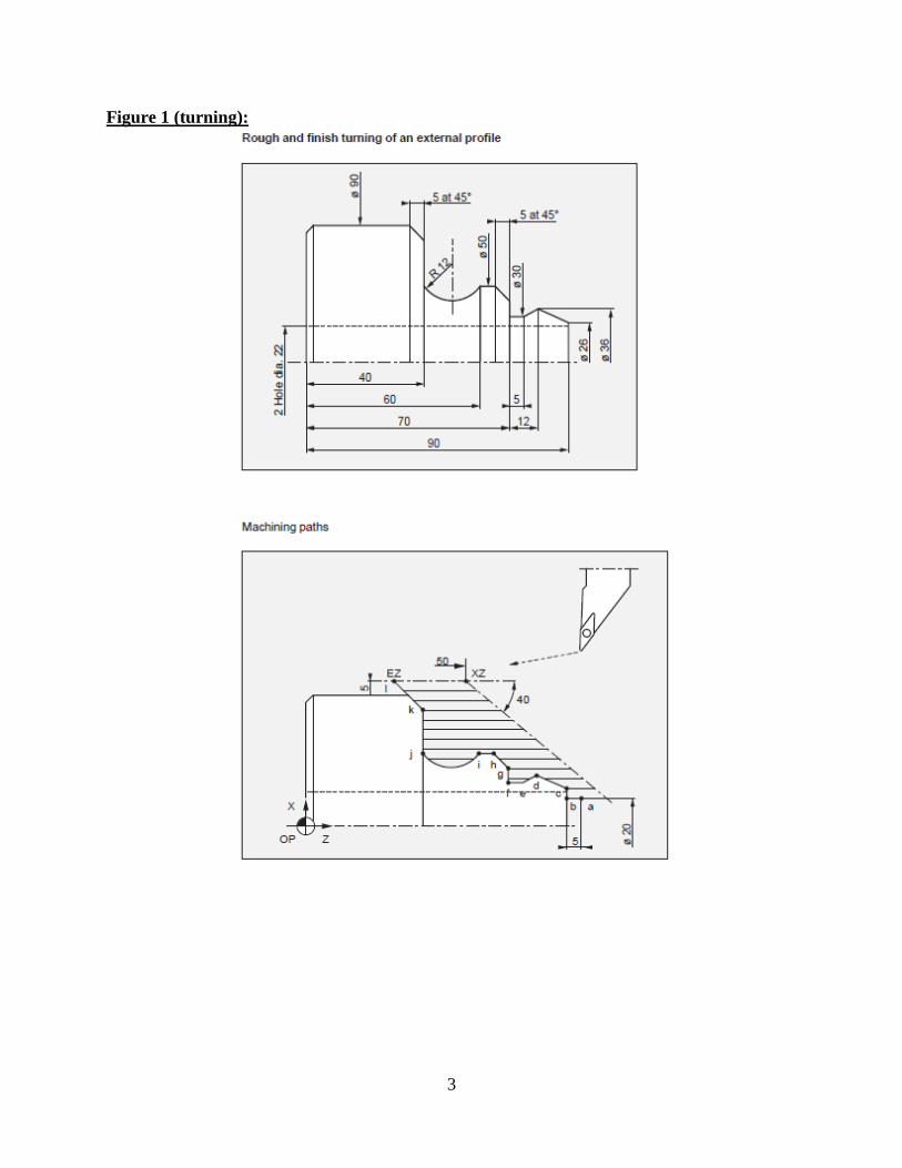
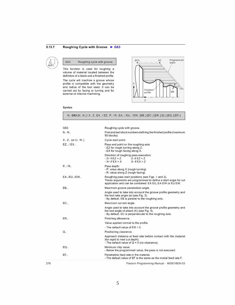
A. Generate a manual part program for the part shown in Figure 1 for the NUM Flexium 68. This
task involves the use of G64, turning/facing cycle (additional info is given in pages 5-10). This
cycle is used to generate a profile from a workpiece with an arbitrary shape. The maximum
depth of cut you can use is 2mm. The maximum spindle speed should not exceed 3500rpm
(G92) and the spindle speed and feed rate is 200rpm, 0.25 mm/rev for roughing and 250rpm, 0.1
mm/rev for finishing. The tool holder and offset information is saved in T01 D01 for roughing
and T03 D03 for finishing. The tool change should occur in X150 Z150. The maximum groove
penetration angle should be set at -145 degrees, positioning clearance should be set at 2mm, and
the minimum chip value should be set at 1mm.
PART 2 (Milling)
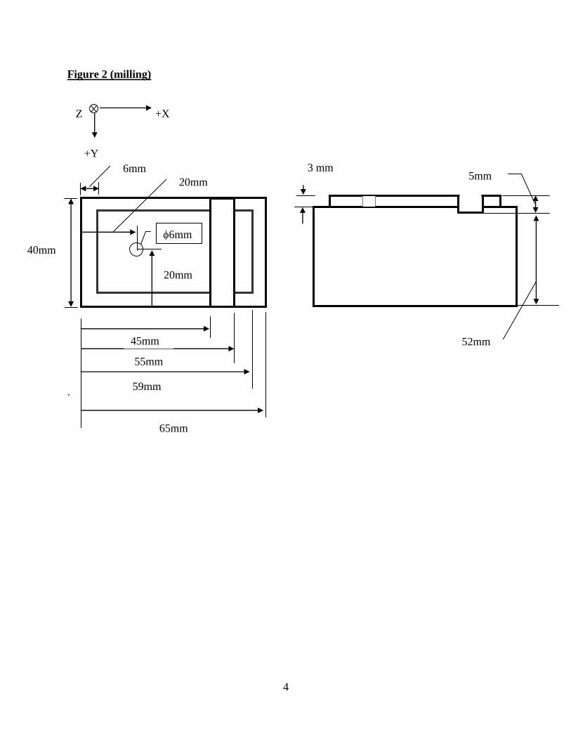
Generate a part program using the software “Walli” for the part shown in Figure 2 for the
Cybermill CNC milling machine. Once the program is completed, simulate the program for
verification, and then run the program on the Cybermill using the tool.
The diameter of the end milling you will be using is 6 mm (use T word for this). Include the
following values in the program.
Spindle speed: 7 (3500 rpm)
Spindle rotation clockwise: M03
Feed rate: 4 (250 mm/min)
Workpiece clamp: M68
The Cybermill has predetermined spindle speed and feed rate as follows:
0 1 2 3 4 5 6 7 8 9
Feed rate (mm/min) 50 100 150 200 250 300 350 400 450 500
Spindle speed (rpm) Off 500 1000 1500 2000 2500 3000 3500 4000 4500
The home position of the Cybermill is the upper left corner (from your view), positive X and Y
directions are to your right and toward you facing the machine. The distance from the tip of the
tool to the top of the workpiece is 29 mm. The coordinate of the upper left corner of the
workpiece is (3,3) after the part is clamped in position. Limit the maximum depth of cut per pass
to 3 mm.
2
For the outside step machining, use two paths to remove all the material.
For drilling, use G82 and D (2 seconds for dwell time) and set the feed to 1 (100 mm/min).
For slotting of the middle section, start the cutting from the left side and complete the cycle.
Note: lift up the cutting tool before you move to the next position using rapid mode!!
Once the part program is completed, show it TA for running the program.
% The report must contain a cover page, a brief objective of lab., printouts of part programs and
corresponding drawings and parts, your discussion and conclusions. The report must be typed.
3
Figure 1 (turning):
4
Figure 2 (milling)
Z +X
+Y
.
6mm
m
65mm
59mm
3 mm 5mm
55mm
45mm
20mm
52mm
20mm
40mm
6mm
5
6

7
8

9
10


![Naruto 576 [manga-worldjap.com]](https://img.pdfslide.us/doc/110x75/568bf4ea1a28ab89339fc202/naruto-576-manga-worldjapcom.jpg)