Embed Size (px)
Citation preview

Page 1 of 18
Name (Print)__________________________________________________________________
(Last) (First)
ME 323 - Mechanics of Materials
Exam # 1
Date: October 5, 2016 Time: 8:00 – 10:00 PM
Instructions:
Circle your lecturer’s name and your class meeting time.
Gonzalez Krousgrill Zhao Sadeghi
4:30-5:20PM 11:30-12:20PM 12:30-1:20PM 2:30-3:20PM
Begin each problem in the space provided on the examination sheets. If additional space is required,
use the paper provided.
Work on one side of each sheet only, with only one problem on a sheet.
Please remember that for you to obtain maximum credit for a problem, you must present your solution
clearly.
Accordingly,
coordinate systems must be clearly identified,
free body diagrams must be shown,
units must be stated,
write down clarifying remarks,
state your assumptions, etc.
If your solution cannot be followed, it will be assumed that it is in error.
When handing in the test, make sure that ALL SHEETS are in the correct sequential order.
Remove the staple and restaple, if necessary.
Prob. 1 ______________________
Prob. 2 ______________________
Prob. 3 ______________________
Prob. 4 ______________________
Total ________________________

Page 2 of 18
Useful Equations
ex
=1
Es
x-n s
y+s
z( )éë
ùû+aDT
ey
=1
Es
y-n s
x+s
z( )éë
ùû +aDT
ez=
1
Es
z-n s
x+s
y( )éë
ùû+aDT
gxy
=1
Gt
xyg
xz=
1
Gt
xzg
yz=
1
Gt
yz
G =E
2(1+ v)
0
4
4 4
( ) dx
( ) ( )
polar area moment for solid circular cross section32
( ) polar a32
p
L
p p
p
op i
Tr
I
T x TL
G x I x GI
dI
I d d
3
4
rea moment for a circular hollow cross section
1 second area moment for a rectangular cross section
12
second area moment for a circular cross section64
I bh
dI
0 0
cos sin
L LF FL
e dx Tdx e L TEA EA
e u v
Yield Strength failure StressFactor of Safety or
Allowable Stress Stress member
Page 3 of 18
ME 323 Examination # 1 Name ___________________________________
October 5, 2016 (Print) (Last) (First)
Instructor _______________________________
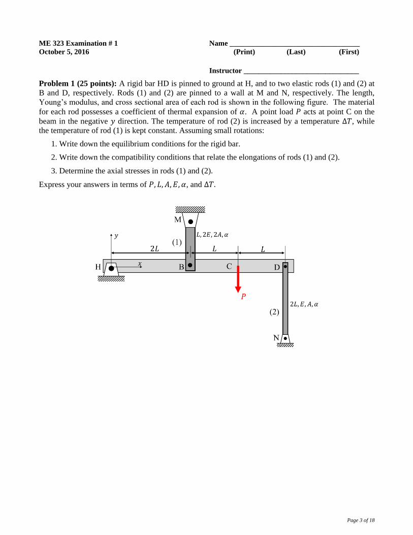
Problem 1 (25 points): A rigid bar HD is pinned to ground at H, and to two elastic rods (1) and (2) at
B and D, respectively. Rods (1) and (2) are pinned to a wall at M and N, respectively. The length,
Young’s modulus, and cross sectional area of each rod is shown in the following figure. The material
for each rod possesses a coefficient of thermal expansion of 𝛼. A point load 𝑃 acts at point C on the
beam in the negative 𝑦 direction. The temperature of rod (2) is increased by a temperature Δ𝑇, while
the temperature of rod (1) is kept constant. Assuming small rotations:
1. Write down the equilibrium conditions for the rigid bar.
2. Write down the compatibility conditions that relate the elongations of rods (1) and (2).
3. Determine the axial stresses in rods (1) and (2).
Express your answers in terms of 𝑃, 𝐿, 𝐴, 𝐸, 𝛼, and Δ𝑇.

Page 4 of 18
Solution: 1. Let 𝐹1 and 𝐹2 represent the tensile axial forces carried by rods (1) and (2) respectively.
From the FBD of beam HD,
Σ𝑀𝐻 = 𝐹1(2𝐿) − 𝑃(3𝐿) − 𝐹2(4𝐿) = 0
⇒ 𝐹1 − 2𝐹2 =3
2𝑃 (1.1)
2. From the (exaggerated) figure showing the displaced points B’, C’ and D’, where 𝑢𝐵 and 𝑢𝐷
represent the downward displacements of B and D respectively,
𝑢𝐵
2𝐿=
𝑢𝐷
4𝐿⇒ 2𝑢𝐵 = 𝑢𝐷 (1.2)
The rotation indicated represents and
elongation of rod (1) and a shortening of
rod (2), i.e.
𝑢𝐵 = 𝑒1; 𝑢𝐷 = −𝑒2 (1.3𝑎)
⇒ 2𝑒1 = −𝑒2 (1.3𝑏)
The elongations can be written in terms of the tensile loads carried, and temperature rise as:
𝑒1 =𝐹1𝐿1
𝐸1𝐴1=
𝐹1𝐿
(2𝐸)(2𝐴)= 0.25
𝐹1𝐿
𝐸𝐴(1.4𝑎)
𝑒2 =𝐹2𝐿2
𝐸2𝐴2+ 𝐿2𝛼Δ𝑇 =
2𝐹2𝐿
𝐸𝐴+ 2𝐿𝛼Δ𝑇 (1.4𝑏)

Page 5 of 18
3. From (4.3b), (4.4a), and (4.4b),
2 × 0.25𝐹1𝐿
𝐸𝐴= −
2𝐹2𝐿
𝐸𝐴− 2𝐿𝛼Δ𝑇
⇒ 𝐹1 + 4𝐹2 = −4𝐸𝐴𝛼Δ𝑇 (1.5) Solving (4.1) and (4.5),
𝐹1 = −4
3𝐸𝐴𝛼Δ𝑇 + 𝑃 ; 𝐹2 = −
2
3𝐸𝐴𝛼Δ𝑇 −
1
4𝑃 (1.6)
Therefore, the axial stresses,
𝜎1 =𝐹1
2𝐴= −
2
3𝐸𝛼Δ𝑇 +
𝑃
2𝐴
𝜎2 =𝐹1
𝐴= −
2
3𝐸𝛼Δ𝑇 −
𝑃
4𝐴

Page 6 of 18
ME 323 Examination # 1 Name ___________________________________
October 5, 2016 (Print) (Last) (First)
Instructor _______________________________
Problem 2 (30 points): A shaft is made up of three components: a solid circular shaft (1) of length 2L
and diameter d; solid circular shaft (2) of length L and diameter 2d; and circular-cross section tubular
shaft (3) of length 3L, outer diameter of 4d and inner diameter of 3d. All three components are made of
the same material having a shear modulus of G. Shafts (1) and (2) are connected by a thin, rigid
connector C, whereas shafts (2) and (3) are connected by a rigid connector D. Shaft 1 is rigidly
attached to ground at B. Torques T and 2T are applied to C and D, respectively, as shown in the figure
below. It is desired to know the torque carried by each of the shaft components. To this end:
a) Draw free body diagrams (FBDs) of connectors C and D below. Write down the appropriate
equilibrium equations from these FBDs.
b) Write down the torque/rotation equations for the three shaft components.
c) Write down the appropriate compatibility equations.
d) Solve for the torques in the three shaft components.
Express your final answers in terms of T, L, d and G.
Page 7 of 18
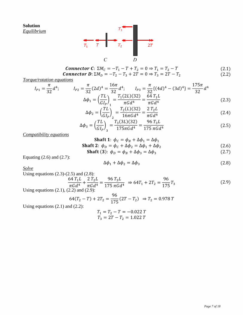
Solution
Equilibrium
𝑪𝒐𝒏𝒏𝒆𝒄𝒕𝒐𝒓 𝑪: Σ𝑀𝐶 = −𝑇1 − 𝑇 + 𝑇2 = 0 ⇒ 𝑇1 = 𝑇2 − 𝑇 (2.1) 𝑪𝒐𝒏𝒏𝒆𝒄𝒕𝒐𝒓 𝑫: Σ𝑀𝐷 = −𝑇2 − 𝑇3 + 2𝑇 = 0 ⇒ 𝑇3 = 2𝑇 − 𝑇2 (2.2)
Torque/rotation equations
𝐼𝑃1 =𝜋
32𝑑4; 𝐼𝑃2 =
𝜋
32(2𝑑)4 =
16𝜋
32𝑑4; 𝐼𝑃3 =
𝜋
32{(4𝑑)4 − (3𝑑)4} =
175𝜋
32𝑑4
Δ𝜙1 = (𝑇𝐿
𝐺𝐼𝑃)
1
=𝑇1(2𝐿)(32)
𝜋𝐺𝑑4=
64 𝑇1𝐿
𝜋𝐺𝑑4 (2.3)
Δ𝜙2 = (𝑇𝐿
𝐺𝐼𝑃)
2
=𝑇2(𝐿)(32)
16𝜋𝐺𝑑4=
2 𝑇2𝐿
𝜋𝐺𝑑4 (2.4)
Δ𝜙3 = (𝑇𝐿
𝐺𝐼𝑃)
3
=𝑇3(3𝐿)(32)
175𝜋𝐺𝑑4=
96 𝑇3𝐿
175 𝜋𝐺𝑑4 (2.5)
Compatibility equations 𝐒𝐡𝐚𝐟𝐭 𝟏: 𝜙𝐶 = 𝜙𝐵 + Δ𝜙1 = Δ𝜙1
𝐒𝐡𝐚𝐟𝐭 𝟐: 𝜙𝐷 = 𝜙𝐶 + Δ𝜙2 = Δ𝜙1 + Δ𝜙2 (2.6)
𝐒𝐡𝐚𝐟𝐭 (𝟑): 𝜙𝐷 = 𝜙𝐵 + Δ𝜙3 = Δ𝜙3 (2.7)
Equating (2.6) and (2.7):
Δ𝜙1 + Δ𝜙2 = Δ𝜙3 (2.8) Solve
Using equations (2.3)-(2.5) and (2.8): 64 𝑇1𝐿
𝜋𝐺𝑑4+
2 𝑇2𝐿
𝜋𝐺𝑑4=
96 𝑇3𝐿
175 𝜋𝐺𝑑4 ⇒ 64𝑇1 + 2𝑇2 =
96
175𝑇3 (2.9)
Using equations (2.1), (2.2) and (2.9):
64(𝑇2 − 𝑇) + 2𝑇2 =96
175(2𝑇 − 𝑇2) ⇒ 𝑇2 = 0.978 𝑇
Using equations (2.1) and (2.2):
𝑇1 = 𝑇2 − 𝑇 = −0.022 𝑇 𝑇3 = 2𝑇 − 𝑇2 = 1.022 𝑇

Page 8 of 18
ME 323 Examination # 1 Name ___________________________________
October 5, 2016 (Print) (Last) (First)
Instructor _______________________________
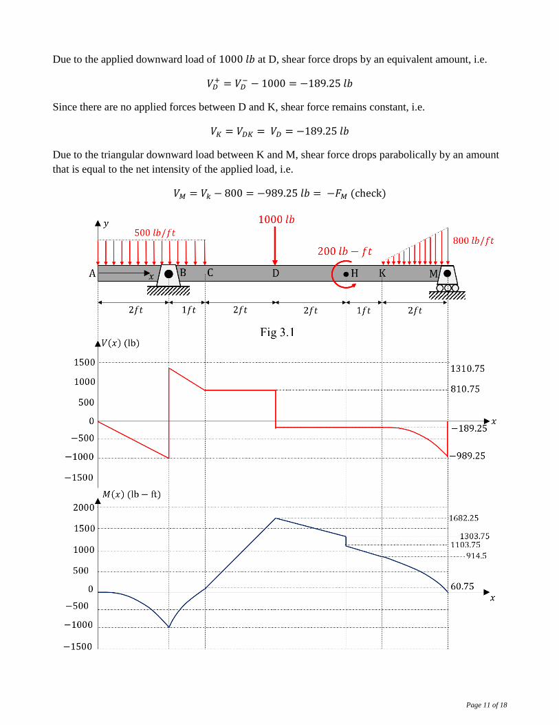
Problem 3 (25 Points): A simply supported beam shown in Fig 3.1, is 10 𝑓𝑡 long and is supported at B
and M. It is subjected to the following loads as shown. The cross section of the beam is uniform
rectangular of height 4 𝑖𝑛 and width 2 𝑖𝑛 as shown in Fig 3.2. For the state of loading shown:
1. Construct shear force and bending moment diagrams for the beam AM. Mark numerical values for
points A through M along with max/min values on these diagrams for the shear, and moment
diagrams respectively. Provide justification for your diagrams in terms of calculations.

Page 9 of 18
2. Determine the cross section (𝑥), and locations (𝑦) of the max bending normal (flexural) stress in
the beam. Also determine the magnitude of the corresponding flexural stress. State whether the
stress is compressive, or tensile. Represent the stress element at this location, and label the non-
zero stress components in Fig 3.3.
Page 10 of 18
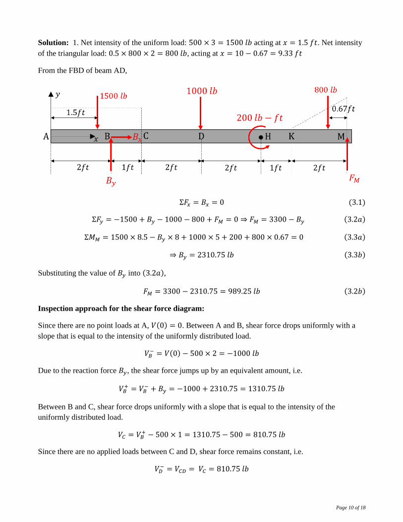
Solution: 1. Net intensity of the uniform load: 500 × 3 = 1500 𝑙𝑏 acting at 𝑥 = 1.5 𝑓𝑡. Net intensity
of the triangular load: 0.5 × 800 × 2 = 800 𝑙𝑏, acting at 𝑥 = 10 − 0.67 = 9.33 𝑓𝑡
From the FBD of beam AD,
Σ𝐹𝑥 = 𝐵𝑥 = 0 (3.1)
Σ𝐹𝑦 = −1500 + 𝐵𝑦 − 1000 − 800 + 𝐹𝑀 = 0 ⇒ 𝐹𝑀 = 3300 − 𝐵𝑦 (3.2𝑎)
Σ𝑀𝑀 = 1500 × 8.5 − 𝐵𝑦 × 8 + 1000 × 5 + 200 + 800 × 0.67 = 0 (3.3𝑎)
⇒ 𝐵𝑦 = 2310.75 𝑙𝑏 (3.3𝑏)
Substituting the value of 𝐵𝑦 into (3.2𝑎),
𝐹𝑀 = 3300 − 2310.75 = 989.25 𝑙𝑏 (3.2𝑏)
Inspection approach for the shear force diagram:
Since there are no point loads at A, 𝑉(0) = 0. Between A and B, shear force drops uniformly with a
slope that is equal to the intensity of the uniformly distributed load.
𝑉𝐵− = 𝑉(0) − 500 × 2 = −1000 𝑙𝑏
Due to the reaction force 𝐵𝑦, the shear force jumps up by an equivalent amount, i.e.
𝑉𝐵+ = 𝑉𝐵
− + 𝐵𝑦 = −1000 + 2310.75 = 1310.75 𝑙𝑏
Between B and C, shear force drops uniformly with a slope that is equal to the intensity of the
uniformly distributed load.
𝑉𝐶 = 𝑉𝐵+ − 500 × 1 = 1310.75 − 500 = 810.75 𝑙𝑏
Since there are no applied loads between C and D, shear force remains constant, i.e.
𝑉𝐷− = 𝑉𝐶𝐷 = 𝑉𝐶 = 810.75 𝑙𝑏
Page 11 of 18
Due to the applied downward load of 1000 𝑙𝑏 at D, shear force drops by an equivalent amount, i.e.
𝑉𝐷+ = 𝑉𝐷
− − 1000 = −189.25 𝑙𝑏
Since there are no applied forces between D and K, shear force remains constant, i.e.
𝑉𝐾 = 𝑉𝐷𝐾 = 𝑉𝐷 = −189.25 𝑙𝑏
Due to the triangular downward load between K and M, shear force drops parabolically by an amount
that is equal to the net intensity of the applied load, i.e.
𝑉𝑀 = 𝑉𝑘 − 800 = −989.25 𝑙𝑏 = −𝐹𝑀 (check)
Page 12 of 18
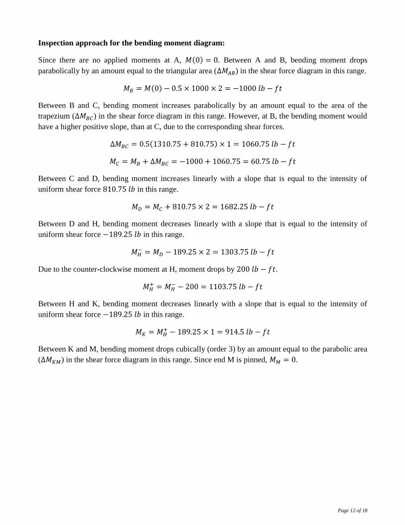
Inspection approach for the bending moment diagram:
Since there are no applied moments at A, 𝑀(0) = 0. Between A and B, bending moment drops
parabolically by an amount equal to the triangular area (Δ𝑀𝐴𝐵) in the shear force diagram in this range.
𝑀𝐵 = 𝑀(0) − 0.5 × 1000 × 2 = −1000 𝑙𝑏 − 𝑓𝑡
Between B and C, bending moment increases parabolically by an amount equal to the area of the
trapezium (Δ𝑀𝐵𝐶) in the shear force diagram in this range. However, at B, the bending moment would
have a higher positive slope, than at C, due to the corresponding shear forces.
Δ𝑀𝐵𝐶 = 0.5(1310.75 + 810.75) × 1 = 1060.75 𝑙𝑏 − 𝑓𝑡
𝑀𝐶 = 𝑀𝐵 + Δ𝑀𝐵𝐶 = −1000 + 1060.75 = 60.75 𝑙𝑏 − 𝑓𝑡
Between C and D, bending moment increases linearly with a slope that is equal to the intensity of
uniform shear force 810.75 𝑙𝑏 in this range.
𝑀𝐷 = 𝑀𝐶 + 810.75 × 2 = 1682.25 𝑙𝑏 − 𝑓𝑡
Between D and H, bending moment decreases linearly with a slope that is equal to the intensity of
uniform shear force −189.25 𝑙𝑏 in this range.
𝑀𝐻− = 𝑀𝐷 − 189.25 × 2 = 1303.75 𝑙𝑏 − 𝑓𝑡
Due to the counter-clockwise moment at H, moment drops by 200 𝑙𝑏 − 𝑓𝑡.
𝑀𝐻+ = 𝑀𝐻
− − 200 = 1103.75 𝑙𝑏 − 𝑓𝑡
Between H and K, bending moment decreases linearly with a slope that is equal to the intensity of
uniform shear force −189.25 𝑙𝑏 in this range.
𝑀𝐾 = 𝑀𝐻+ − 189.25 × 1 = 914.5 𝑙𝑏 − 𝑓𝑡
Between K and M, bending moment drops cubically (order 3) by an amount equal to the parabolic area
(Δ𝑀𝐾𝑀) in the shear force diagram in this range. Since end M is pinned, 𝑀𝑀 = 0.

Page 13 of 18
2. The magnitude of maximum bending moment occurs at D (𝑥 = 5𝑓𝑡). Therefore, maximum flexural
stress also occurs at this cross section. Since the bending moment is positive and the cross section
symmtrical about the neutral plane, maximum tensile stress is experienced at the bottom plane (𝑦 =−2 𝑖𝑛), and maximum compressive stress at the top plane (𝑦 = 2 𝑖𝑛).
𝑀𝑚𝑎𝑥 = 1682.25 𝑙𝑏 − 𝑓𝑡 = 1682.25 × 12 𝑙𝑏 − 𝑖𝑛
For a rectangular cross section,
𝐼𝑧 =𝑏ℎ3
12=
(2)(4)3
12= 10.67 𝑖𝑛4
Therefore, at = 5𝑓𝑡, 𝑦 = −2 𝑖𝑛,
𝜎𝑏𝑜𝑡𝑡𝑜𝑚 = −𝑀𝑚𝑎𝑥(−2)
𝐼𝑧=
1682.25 × 12 × 2
10.67= 3783.88 𝑝𝑠𝑖 = 3.78 𝑘𝑠𝑖
At = 5𝑓𝑡, 𝑦 = +2 𝑖𝑛,
𝜎𝑏𝑜𝑡𝑡𝑜𝑚 = −𝑀𝑚𝑎𝑥(2)
𝐼𝑧= −
1682.25 × 12 × 2
10.67= −3783.88 𝑝𝑠𝑖 = −3.78 𝑘𝑠𝑖
Page 14 of 18
ME 323 Examination # 1 Name ___________________________________
October 5, 2016 (Print) (Last) (First)
Instructor _______________________________
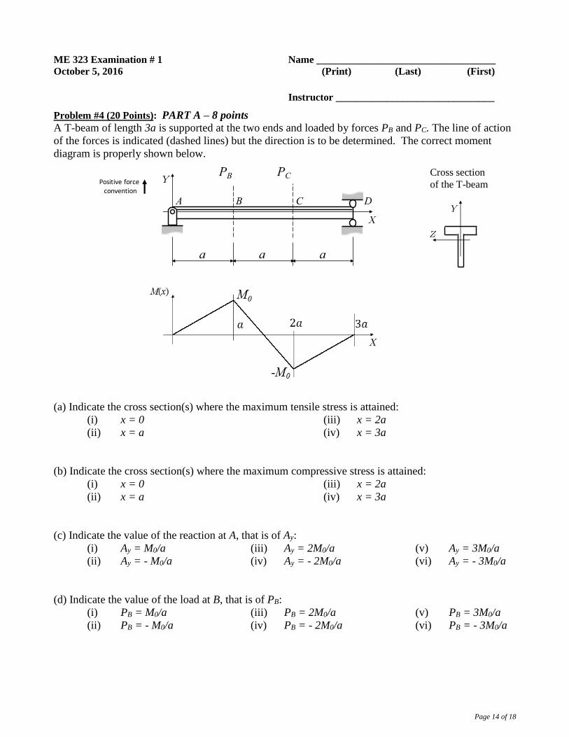
Problem #4 (20 Points): PART A – 8 points
A T-beam of length 3a is supported at the two ends and loaded by forces PB and PC. The line of action
of the forces is indicated (dashed lines) but the direction is to be determined. The correct moment
diagram is properly shown below.
(a) Indicate the cross section(s) where the maximum tensile stress is attained:
(i) x = 0
(ii) x = a
(iii) x = 2a
(iv) x = 3a
(b) Indicate the cross section(s) where the maximum compressive stress is attained:
(i) x = 0
(ii) x = a
(iii) x = 2a
(iv) x = 3a
(c) Indicate the value of the reaction at A, that is of Ay:
(i) Ay = M0/a
(ii) Ay = - M0/a
(iii) Ay = 2M0/a
(iv) Ay = - 2M0/a
(v) Ay = 3M0/a
(vi) Ay = - 3M0/a
(d) Indicate the value of the load at B, that is of PB:
(i) PB = M0/a
(ii) PB = - M0/a
(iii) PB = 2M0/a
(iv) PB = - 2M0/a
(v) PB = 3M0/a
(vi) PB = - 3M0/a
a a a
PB
BA C D
PCPositiveforceconvention
Cross section
of the T-beam
Page 15 of 18
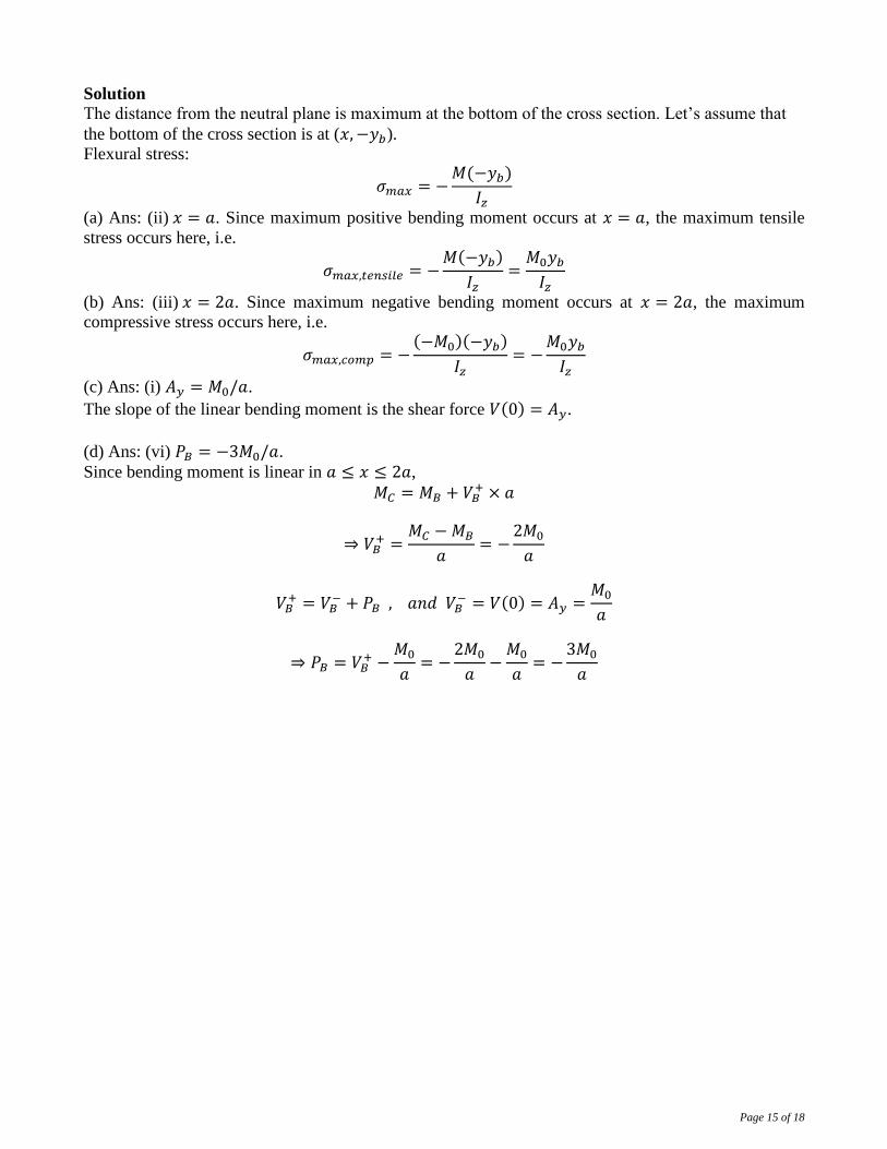
Solution The distance from the neutral plane is maximum at the bottom of the cross section. Let’s assume that
the bottom of the cross section is at (𝑥, −𝑦𝑏).
Flexural stress:
𝜎𝑚𝑎𝑥 = −𝑀(−𝑦𝑏)
𝐼𝑧
(a) Ans: (ii) 𝑥 = 𝑎. Since maximum positive bending moment occurs at 𝑥 = 𝑎, the maximum tensile
stress occurs here, i.e.
𝜎𝑚𝑎𝑥,𝑡𝑒𝑛𝑠𝑖𝑙𝑒 = −𝑀(−𝑦𝑏)
𝐼𝑧=
𝑀0𝑦𝑏
𝐼𝑧
(b) Ans: (iii) 𝑥 = 2𝑎. Since maximum negative bending moment occurs at 𝑥 = 2𝑎, the maximum
compressive stress occurs here, i.e.
𝜎𝑚𝑎𝑥,𝑐𝑜𝑚𝑝 = −(−𝑀0)(−𝑦𝑏)
𝐼𝑧= −
𝑀0𝑦𝑏
𝐼𝑧
(c) Ans: (i) 𝐴𝑦 = 𝑀0/𝑎.
The slope of the linear bending moment is the shear force 𝑉(0) = 𝐴𝑦.
(d) Ans: (vi) 𝑃𝐵 = −3𝑀0/𝑎.
Since bending moment is linear in 𝑎 ≤ 𝑥 ≤ 2𝑎,
𝑀𝐶 = 𝑀𝐵 + 𝑉𝐵+ × 𝑎
⇒ 𝑉𝐵+ =
𝑀𝐶 − 𝑀𝐵
𝑎= −
2𝑀0
𝑎
𝑉𝐵+ = 𝑉𝐵
− + 𝑃𝐵 , 𝑎𝑛𝑑 𝑉𝐵− = 𝑉(0) = 𝐴𝑦 =
𝑀0
𝑎
⇒ 𝑃𝐵 = 𝑉𝐵+ −
𝑀0
𝑎= −
2𝑀0
𝑎−
𝑀0
𝑎= −
3𝑀0
𝑎
Page 16 of 18
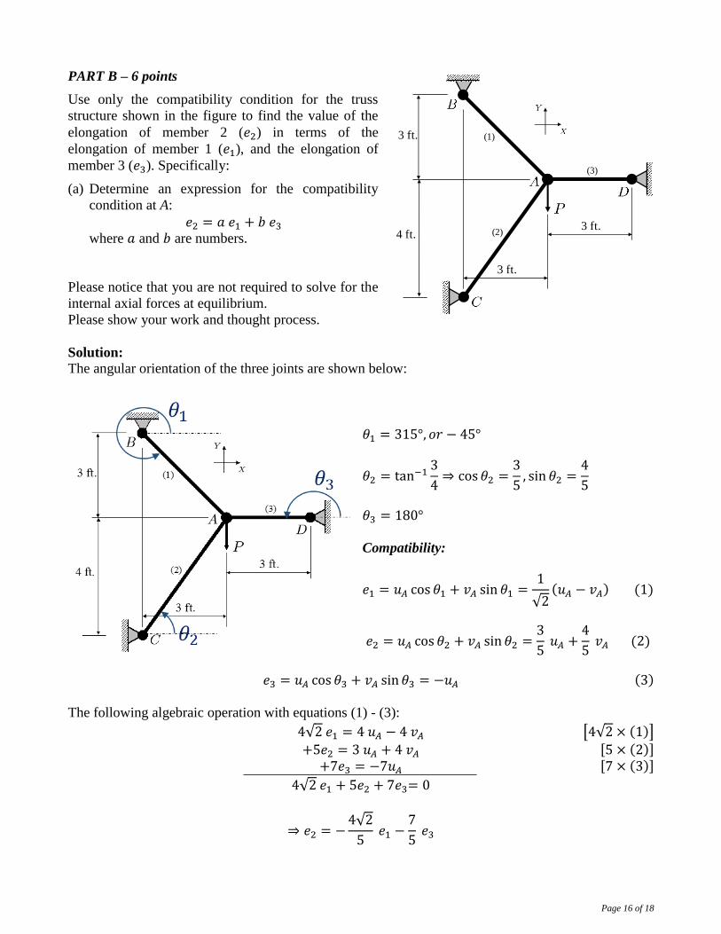
PART B – 6 points
Use only the compatibility condition for the truss
structure shown in the figure to find the value of the
elongation of member 2 (𝑒2) in terms of the
elongation of member 1 (𝑒1), and the elongation of
member 3 (𝑒3). Specifically:
(a) Determine an expression for the compatibility
condition at A:
𝑒2 = 𝑎 𝑒1 + 𝑏 𝑒3 where 𝑎 and 𝑏 are numbers.
Please notice that you are not required to solve for the
internal axial forces at equilibrium.
Please show your work and thought process.
Solution:
The angular orientation of the three joints are shown below:
𝜃1 = 315°, 𝑜𝑟 − 45°
𝜃2 = tan−13
4⇒ cos 𝜃2 =
3
5, sin 𝜃2 =
4
5
𝜃3 = 180°
Compatibility:
𝑒1 = 𝑢𝐴 cos 𝜃1 + 𝑣𝐴 sin 𝜃1 =1
√2(𝑢𝐴 − 𝑣𝐴) (1)
𝑒2 = 𝑢𝐴 cos 𝜃2 + 𝑣𝐴 sin 𝜃2 =3
5 𝑢𝐴 +
4
5 𝑣𝐴 (2)
𝑒3 = 𝑢𝐴 cos 𝜃3 + 𝑣𝐴 sin 𝜃3 = −𝑢𝐴 (3)
The following algebraic operation with equations (1) - (3):
4√2 𝑒1 = 4 𝑢𝐴 − 4 𝑣𝐴 [4√2 × (1)]
+5𝑒2 = 3 𝑢𝐴 + 4 𝑣𝐴 [5 × (2)] +7𝑒3 = −7𝑢𝐴 [7 × (3)]
4√2 𝑒1 + 5𝑒2 + 7𝑒3= 0
⇒ 𝑒2 = −4√2
5 𝑒1 −
7
5 𝑒3
(1)
(2)
(3)
3 ft.
4 ft.
3 ft.
3 ft.

Page 17 of 18
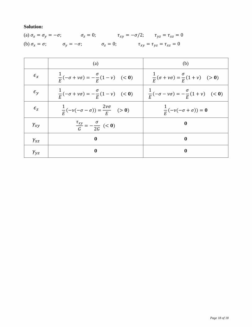
PART C – 6 points
For each state of plane stress shown below, i.e., for configurations (a) and (b), indicate whether each
component of the state of strain is:
= 0 (equal to zero)
> 0 (greater than zero)
< 0 (less than zero)
The material is linear elastic with Poisson’s ratio 𝜈 (0 < 𝜈 < 0.5), and the deformations are small.
(a) (b)
𝜖𝑥
𝜖𝑦
𝜖𝑧
𝛾𝑥𝑦
𝛾𝑥𝑧
𝛾𝑦𝑧
Fill in with ‘= 0’, ‘> 0’, or ‘< 0’.
(a) (b)
Page 18 of 18
Solution:
(a) 𝜎𝑥 = 𝜎𝑦 = −𝜎; 𝜎𝑧 = 0; 𝜏𝑥𝑦 = −𝜎/2; 𝜏𝑦𝑧 = 𝜏𝑥𝑧 = 0
(b) 𝜎𝑥 = 𝜎; 𝜎𝑦 = −𝜎; 𝜎𝑧 = 0; 𝜏𝑥𝑦 = 𝜏𝑦𝑧 = 𝜏𝑥𝑧 = 0
(a) (b)
𝜖𝑥 1
𝐸(−𝜎 + 𝜈𝜎) = −
𝜎
𝐸(1 − 𝜈) (< 𝟎)
1
𝐸(𝜎 + 𝜈𝜎) =
𝜎
𝐸(1 + 𝜈) (> 𝟎)
𝜖𝑦 1
𝐸(−𝜎 + 𝜈𝜎) = −
𝜎
𝐸(1 − 𝜈) (< 𝟎)
1
𝐸(−𝜎 − 𝜈𝜎) = −
𝜎
𝐸(1 + 𝜈) (< 𝟎)
𝜖𝑧 1
𝐸(−𝜈(−𝜎 − 𝜎)) =
2𝜈𝜎
𝐸 (> 𝟎)
1
𝐸(−𝜈(−𝜎 + 𝜎)) = 𝟎
𝛾𝑥𝑦 𝜏𝑥𝑦
𝐺= −
𝜎
2𝐺 (< 𝟎) 𝟎
𝛾𝑥𝑧 𝟎 𝟎
𝛾𝑦𝑧 𝟎 𝟎