Embed Size (px)
Citation preview

ME 3507: Theory of Machines
Degrees of freedom
Dr. Faraz Junejo
Degree-of-freedom (DoF)• Degree of freedom (also called the mobility M)
of a system can be defined as:
• the number of inputs which need to be provided in
order to create a predictable output;
also:
• the number of independent coordinates required to
define its position.
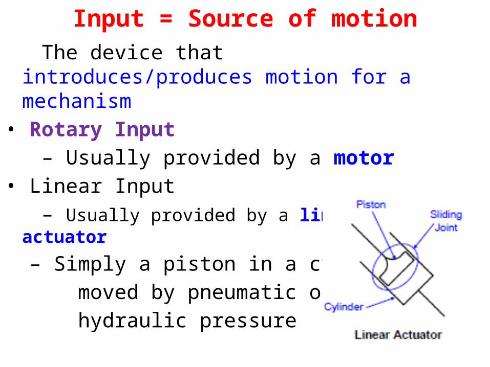
Input = Source of motion The device that introduces/produces motion
for a mechanism• Rotary Input – Usually provided by a motor• Linear Input – Usually provided by a linear actuator
– Simply a piston in a cylinder moved by pneumatic or hydraulic pressure
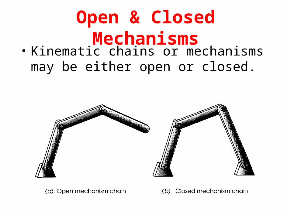
Open & Closed Mechanisms• Kinematic chains or mechanisms may be
either open or closed.
Open & Closed Mechanisms (contd.)
• A closed mechanism will have no open attachment
points or nodes and may have one or more degrees
of freedom.
• An open mechanism of more than one link will
always have more than one degree of freedom, thus
requiring as many actuators (motors) as it has DOF.
Ex- Industrial robot
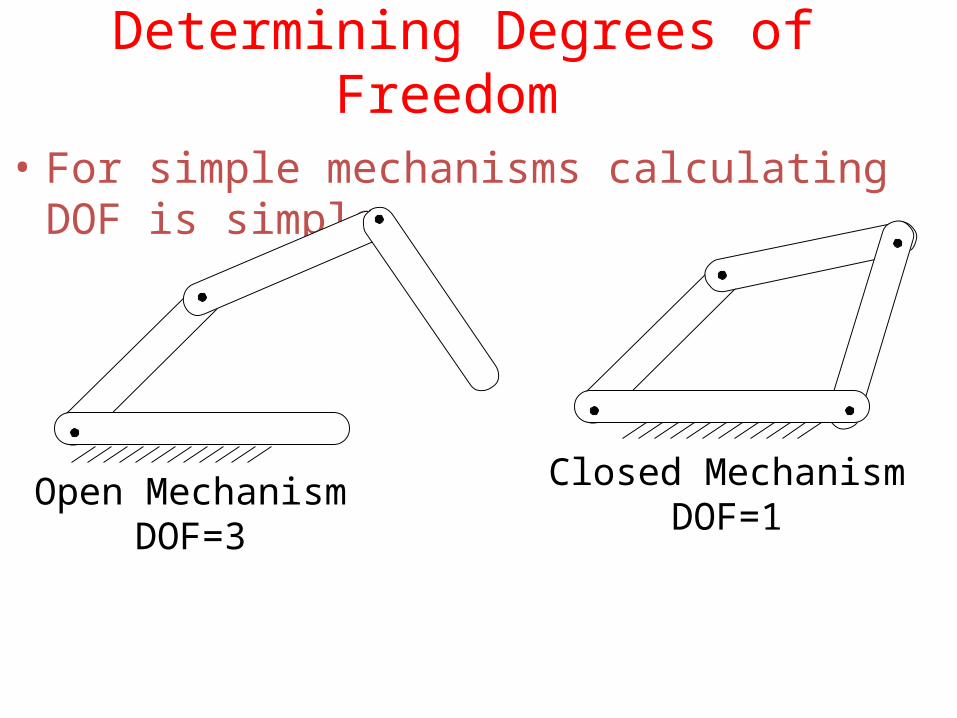
Determining Degrees of Freedom
• For simple mechanisms calculating DOF is simple
Closed MechanismDOF=1
Open MechanismDOF=3
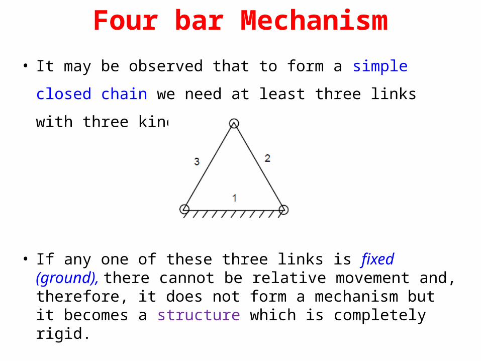
Four bar Mechanism
• It may be observed that to form a simple closed chain we need at least three links with three kinematic pairs.
• If any one of these three links is fixed (ground), there cannot be relative movement and, therefore, it does not form a mechanism but it becomes a structure which is completely rigid.
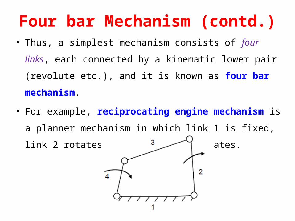
Four bar Mechanism (contd.)• Thus, a simplest mechanism consists of four links, each
connected by a kinematic lower pair (revolute etc.), and it
is known as four bar mechanism.
• For example, reciprocating engine mechanism is a planner
mechanism in which link 1 is fixed, link 2 rotates and link 4
reciprocates.
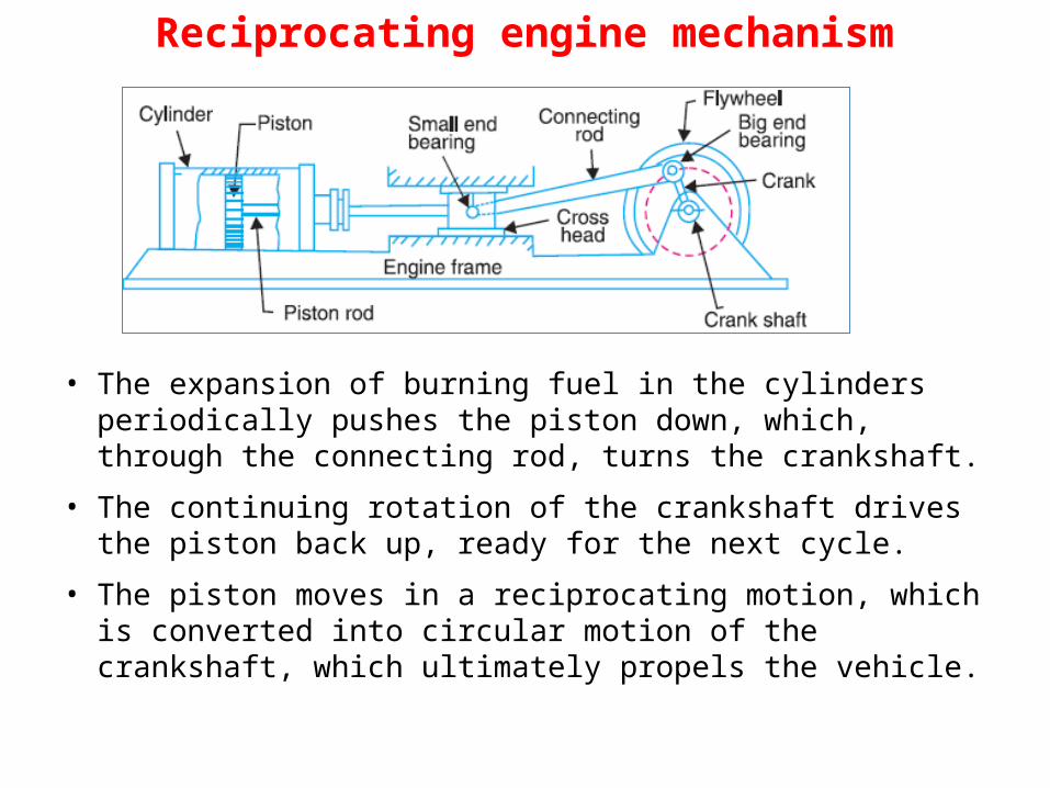
Reciprocating engine mechanism
• The expansion of burning fuel in the cylinders periodically pushes the piston down, which, through the connecting rod, turns the crankshaft.
• The continuing rotation of the crankshaft drives the piston back up, ready for the next cycle.
• The piston moves in a reciprocating motion, which is converted into circular motion of the crankshaft, which ultimately propels the vehicle.
Degree of Freedom in Planar Mechanisms
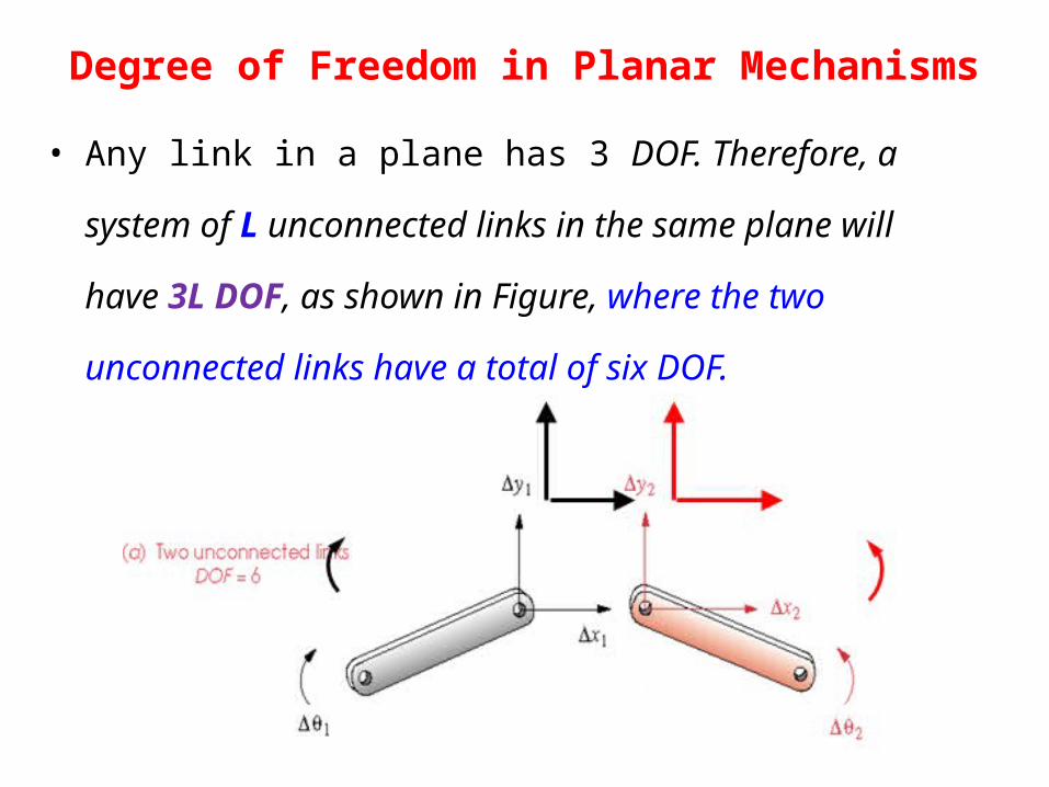
• Any link in a plane has 3 DOF. Therefore, a system of L
unconnected links in the same plane will have 3L DOF, as
shown in Figure, where the two unconnected links have a total
of six DOF.
Degree of Freedom in Planar Mechanisms (contd.)
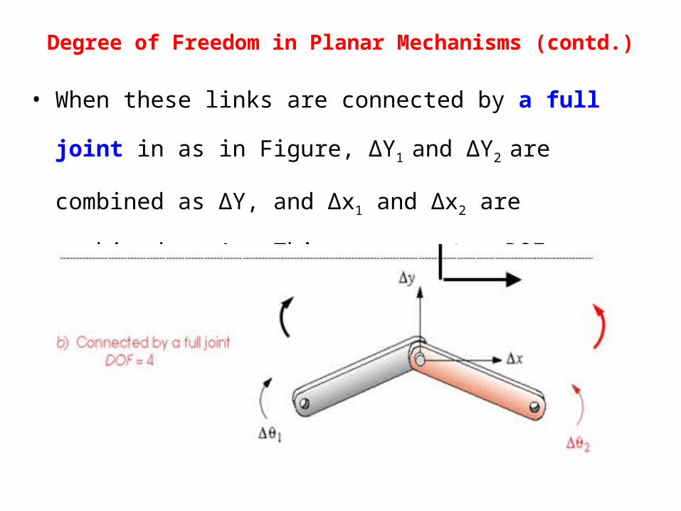
• When these links are connected by a full joint in as in Figure,
ΔY1 and ΔY2 are combined as ΔY, and Δx1 and Δx2 are combined
as Δx. This removes two DOF, leaving four DOF.
Degree of Freedom in Planar Mechanisms
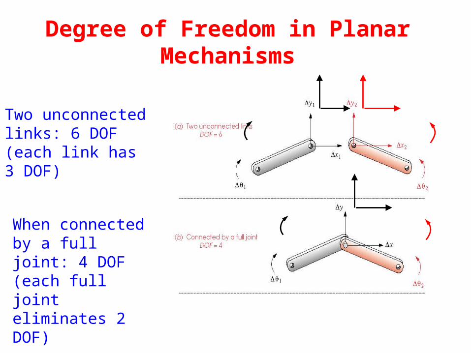
Two unconnected links: 6 DOF(each link has 3 DOF)
When connected by a full joint: 4 DOF(each full joint eliminates 2 DOF)
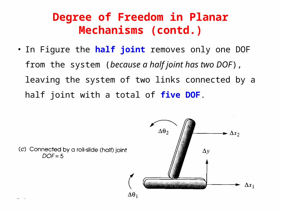
• In Figure the half joint removes only one DOF from the
system (because a half joint has two DOF), leaving the
system of two links connected by a half joint with a total
of five DOF.
Degree of Freedom in Planar Mechanisms (contd.)
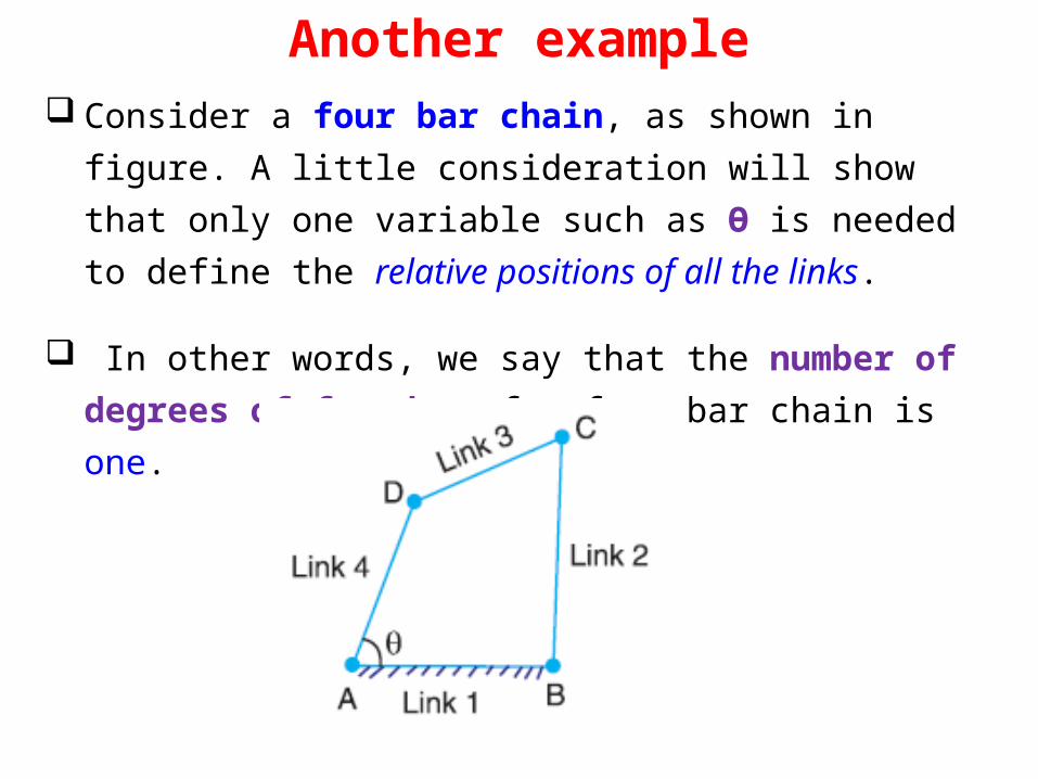
Another example Consider a four bar chain, as shown in figure. A little
consideration will show that only one variable such as Ө is needed to define the relative positions of all the links.
In other words, we say that the number of degrees of freedom of a four bar chain is one.
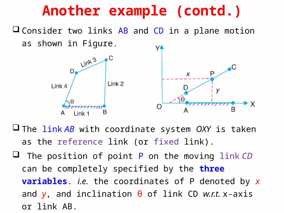
Another example (contd.) Consider two links AB and CD in a plane motion as shown in
Figure.
The link AB with coordinate system OXY is taken as the reference link (or fixed link).
The position of point P on the moving link CD can be completely specified by the three variables. i.e. the coordinates of P denoted by x and y, and inclination θ of link CD w.r.t. x-axis or link AB.
Another example (contd.) In other words, we can say that each link of a mechanism
has three degrees of freedom before it is connected to any
other link.
But when the link CD is connected to the link A B by a
turning pair at A, the position of link CD is now determined
by a single variable θ and thus has one degree of freedom.
We have seen that when a link is connected to a fixed link by
a turning pair (i.e. lower pair), two degrees of freedom are
destroyed.
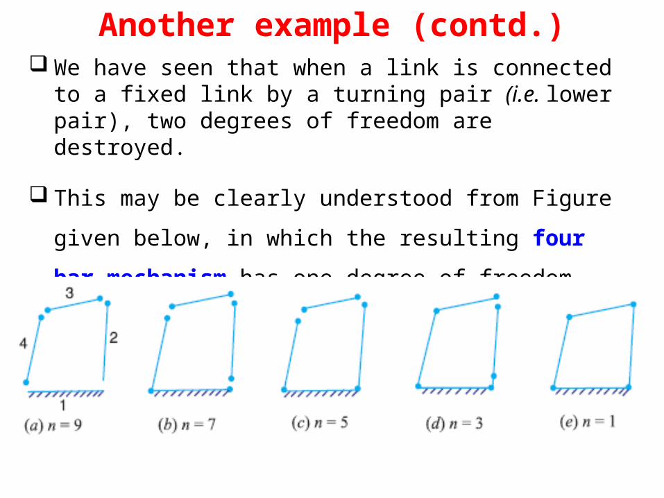
Another example (contd.) We have seen that when a link is connected to a fixed link by a
turning pair (i.e. lower pair), two degrees of freedom are destroyed.
This may be clearly understood from Figure given below, in
which the resulting four bar mechanism has one degree of
freedom.
Determining DoF’s
• Now let us consider a plane mechanism with I
number of links.
• Since in a mechanism, one of the links is to be
fixed, therefore the number of movable links
will be (I - 1) and thus the total number of
degrees of freedom will be 3 (I - 1) before they
are connected to any other link.
Determining DoF’s
• In general, a mechanism with l number of links connected by j number of binary joints or lower pairs (i.e. single degree of freedom pairs) and h number of higher pairs (i.e. two degree of freedom pairs), then the number of degrees of freedom of a mechanism is given by
M = 3 (I - 1) - 2j – h• This equation is called Gruebler’s criterion for the
movability of a mechanism having plane motion.• If there are no two degree of freedom pairs (i.e. higher
pairs), then h = 0. Substituting h = 0 in equation, we haveM = 3 (I - 1) - 2j
• Gruebler’s equation for planar mechanisms
M = 3 (I - 1) - 2j
• Note that the value of j must reflect the value of all joints in
the mechanism; i.e. half joints count as 0.5 b/c they only
remove 1 DOF. A modified form of Gruebler’s equation for
clarity is known as Kutzbach’s modification, which take
into account full and half joints separately;
M = 3 (L – 1) - 2J1- J2
Where
J1= Number of 1 DOF (full) joints
J2= Number of 2 DOF (half) joints

Important Note !!
It should be noted that
Gruebler’s/Kutzbach’s equation has no
information in it about link sizes or
shapes, only their quantity.
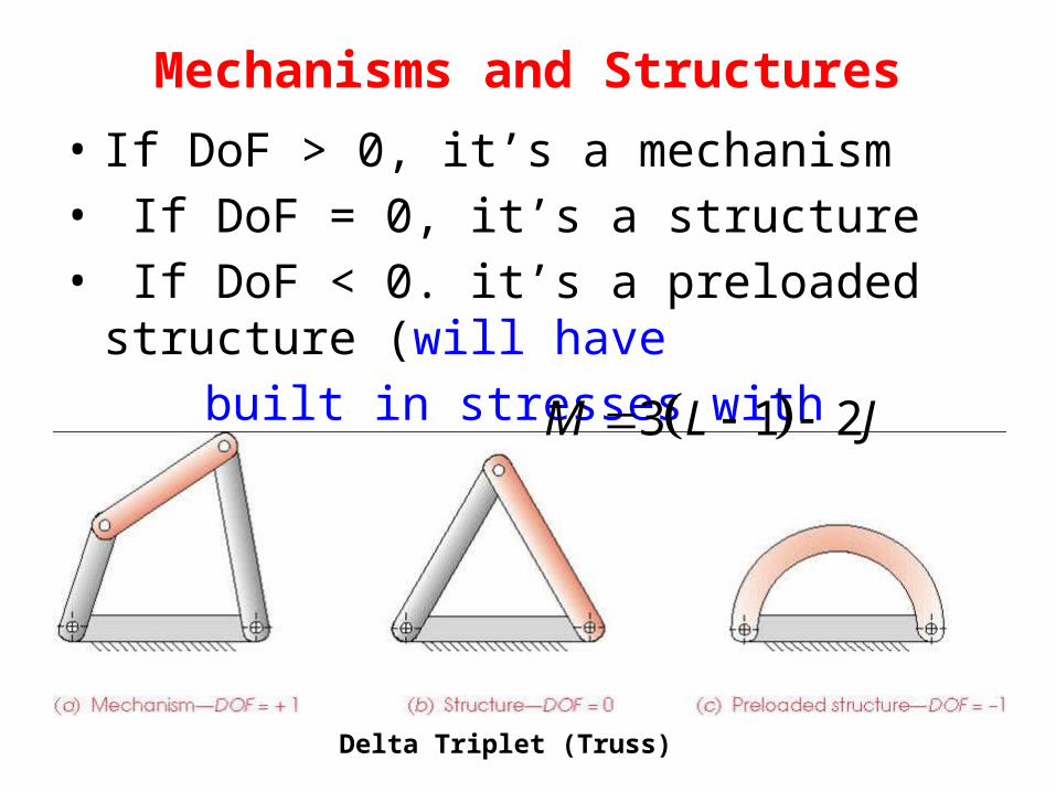
Mechanisms and Structures• If DoF > 0, it’s a mechanism• If DoF = 0, it’s a structure• If DoF < 0. it’s a preloaded structure (will have built in stresses with manufacturing error)
3 1 2M L J
Delta Triplet (Truss)
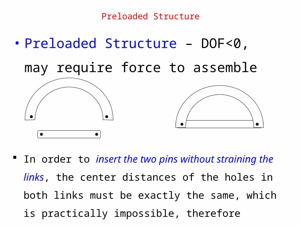
Preloaded Structure
• Preloaded Structure – DOF<0, may
require force to assemble
In order to insert the two pins without straining the links, the
center distances of the holes in both links must be exactly the
same, which is practically impossible, therefore require force
to assemble causing stress in links
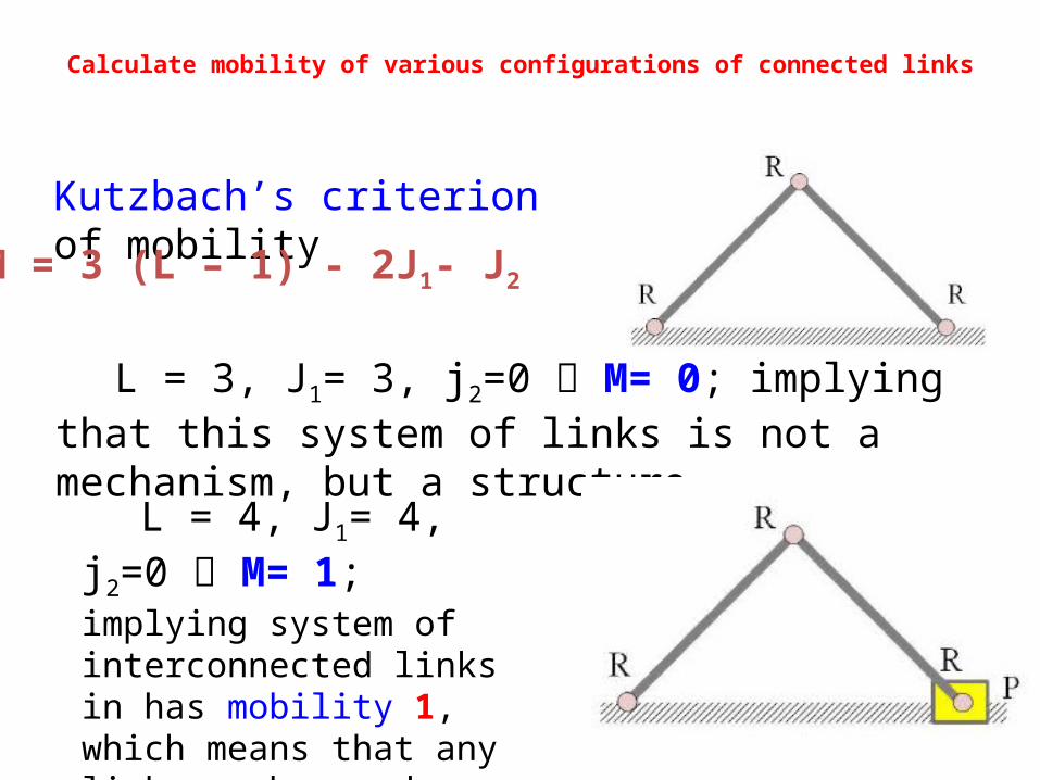
Calculate mobility of various configurations of connected links
Kutzbach’s criterion of mobility
M = 3 (L – 1) - 2J1- J2
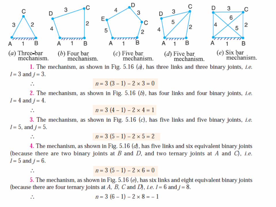
L = 3, J1= 3, j2=0 M= 0; implying that this system of links is not a mechanism, but a structure.
L = 4, J1= 4, j2=0 M= 1; implying system of interconnected links in has mobility 1, which means that any link can be used as input link (driver) in this mechanism.
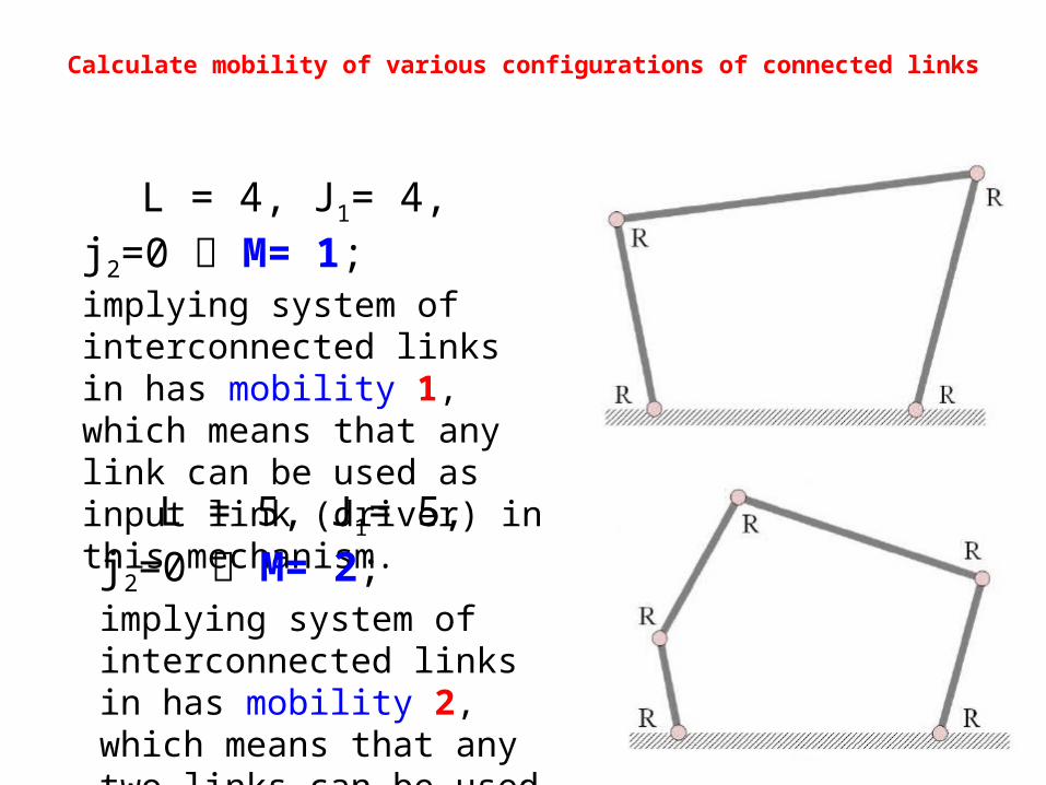
Calculate mobility of various configurations of connected links
L = 4, J1= 4, j2=0 M= 1; implying system of interconnected links in has mobility 1, which means that any link can be used as input link (driver) in this mechanism.
L = 5, J1= 5, j2=0 M= 2; implying system of interconnected links in has mobility 2, which means that any two links can be used as input links (drivers) in this mechanism.
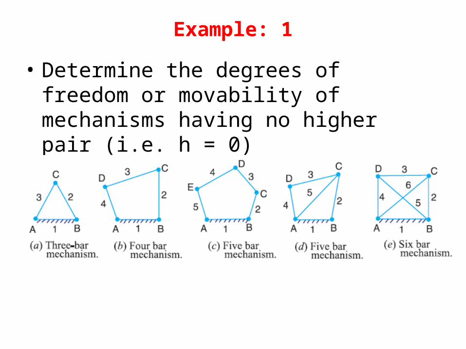
Example: 1
• Determine the degrees of freedom or movability of mechanisms having no higher pair (i.e. h = 0)
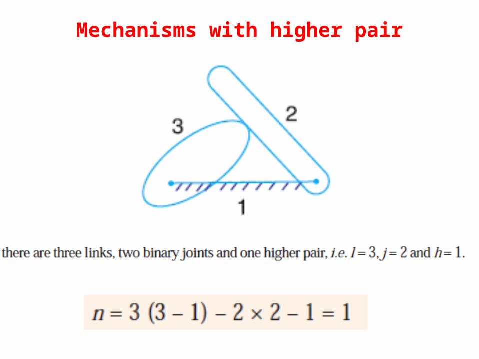
Mechanisms with higher pair

Mechanisms with higher pair (contd.)
Here it has been assumed that the slipping is possible between
the links (i.e. between the wheel and the fixed link).
However if the friction at the contact is high enough to prevent slipping, the joint will be counted as one degree of freedom pair, because only one relative motion will be possible between the links.
Ex- driving car on dry & Icy road.
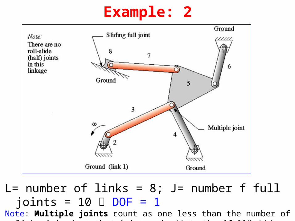
Example: 2
L= number of links = 8; J= number f full joints = 10 DOF = 1Note: Multiple joints count as one less than the number of links joined at that joint
and add to the "full" (J1) category
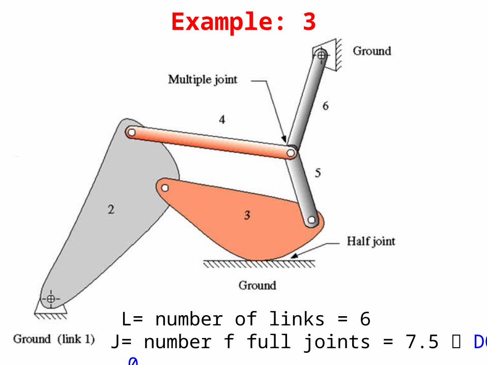
Example: 3
L= number of links = 6J= number f full joints = 7.5 DOF = 0
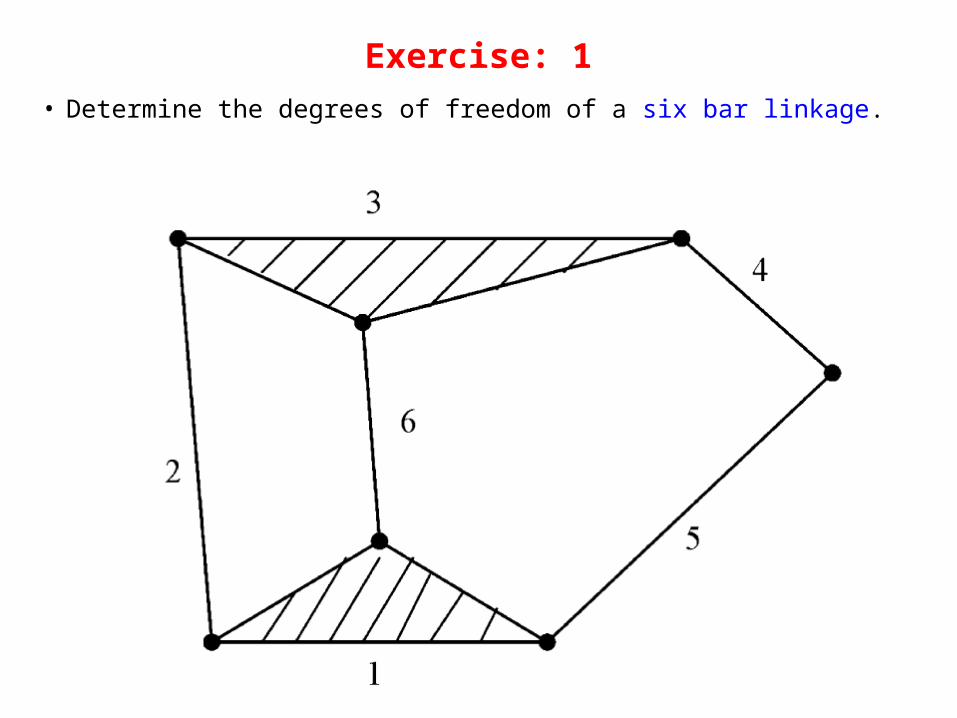
Exercise: 1
• Determine the degrees of freedom of a six bar linkage.
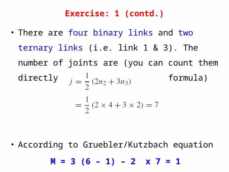
Exercise: 1 (contd.)
• There are four binary links and two ternary links (i.e.
link 1 & 3). The number of joints are (you can count
them directly or use the following formula)
• According to Gruebler/Kutzbach equation
M = 3 (6 – 1) – 2 x 7 = 1
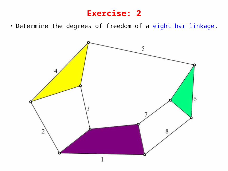
Exercise: 2
• Determine the degrees of freedom of a eight bar linkage.
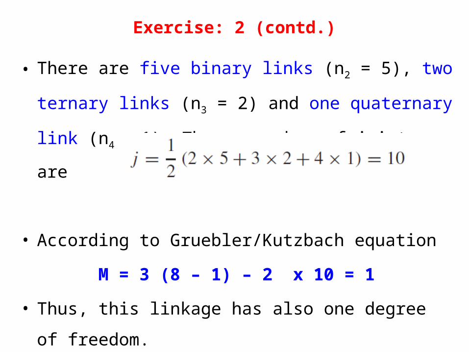
Exercise: 2 (contd.)
• There are five binary links (n2 = 5), two ternary links (n3
= 2) and one quaternary link (n4 = 1). Thus, number of
joints are
• According to Gruebler/Kutzbach equation
M = 3 (8 – 1) – 2 x 10 = 1
• Thus, this linkage has also one degree of freedom.
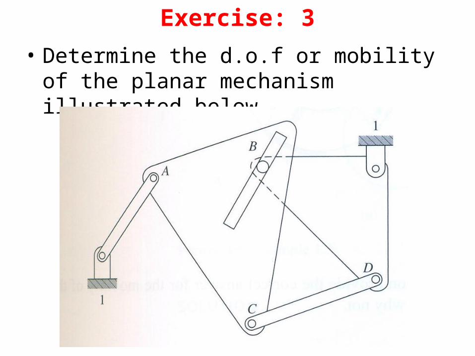
Exercise: 3• Determine the d.o.f or mobility of the planar
mechanism illustrated below
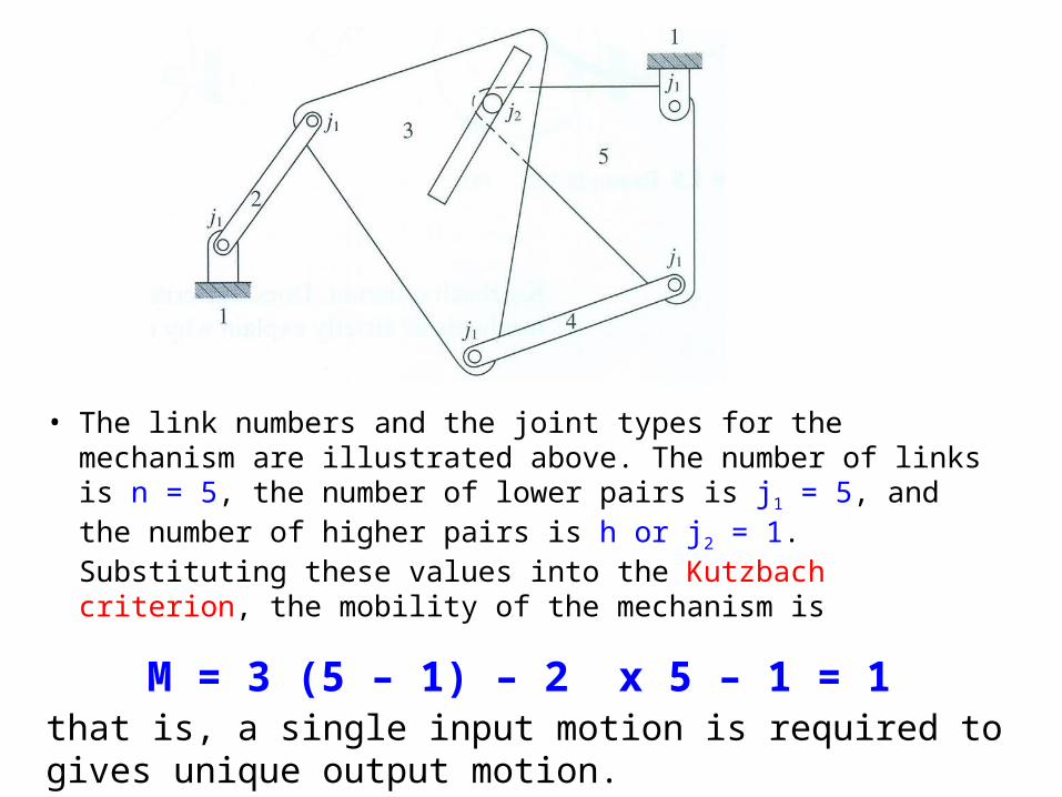
• The link numbers and the joint types for the mechanism are illustrated above. The number of links is n = 5, the number of lower pairs is j1 = 5, and the number of higher pairs is h or j2 = 1. Substituting these values into the Kutzbach criterion, the mobility of the mechanism is
M = 3 (5 – 1) – 2 x 5 – 1 = 1that is, a single input motion is required to gives unique output motion.
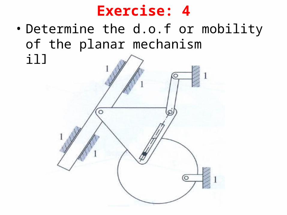
Exercise: 4• Determine the d.o.f or mobility of the planar
mechanism illustrated below
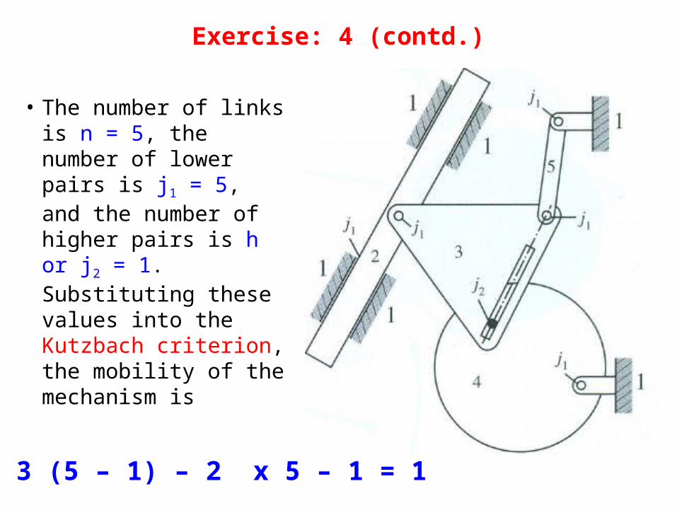
• The number of links is n = 5, the number of lower pairs is j1 = 5, and the number of higher pairs is h or j2 = 1. Substituting these values into the Kutzbach criterion, the mobility of the mechanism is
M = 3 (5 – 1) – 2 x 5 – 1 = 1
Exercise: 4 (contd.)
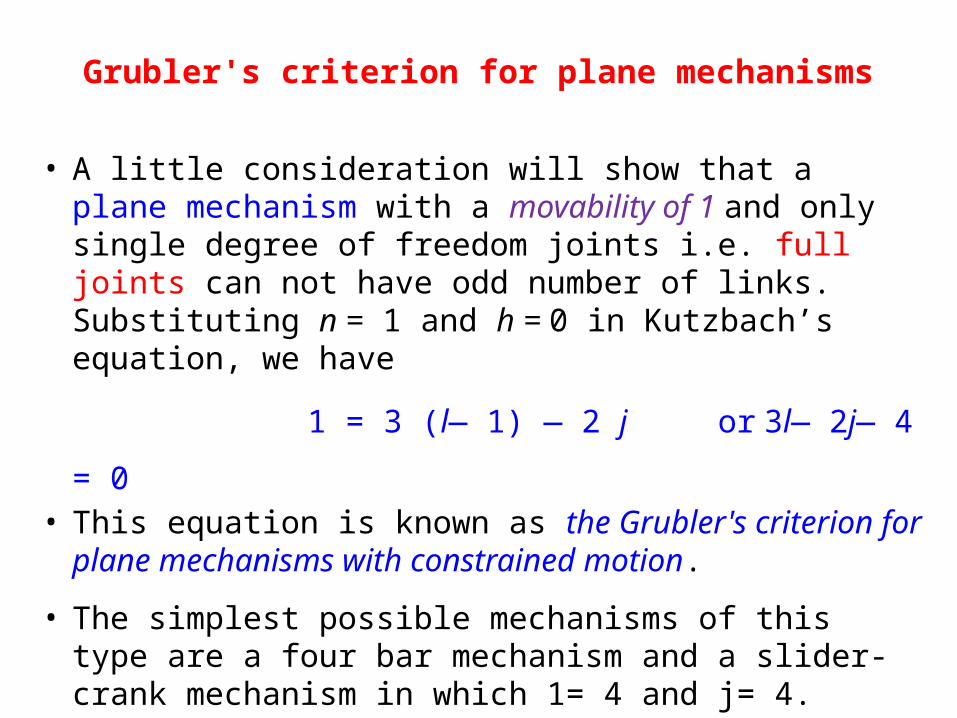
Grubler's criterion for plane mechanisms
• A little consideration will show that a plane mechanism with a movability of 1 and only single degree of freedom joints i.e. full joints can not have odd number of links. Substituting n = 1 and h = 0 in Kutzbach’s equation, we have
1 = 3 (l— 1) — 2 j or 3l— 2j— 4 = 0• This equation is known as the Grubler's criterion for
plane mechanisms with constrained motion.
• The simplest possible mechanisms of this type are a four bar mechanism and a slider-crank mechanism in which 1= 4 and j= 4.
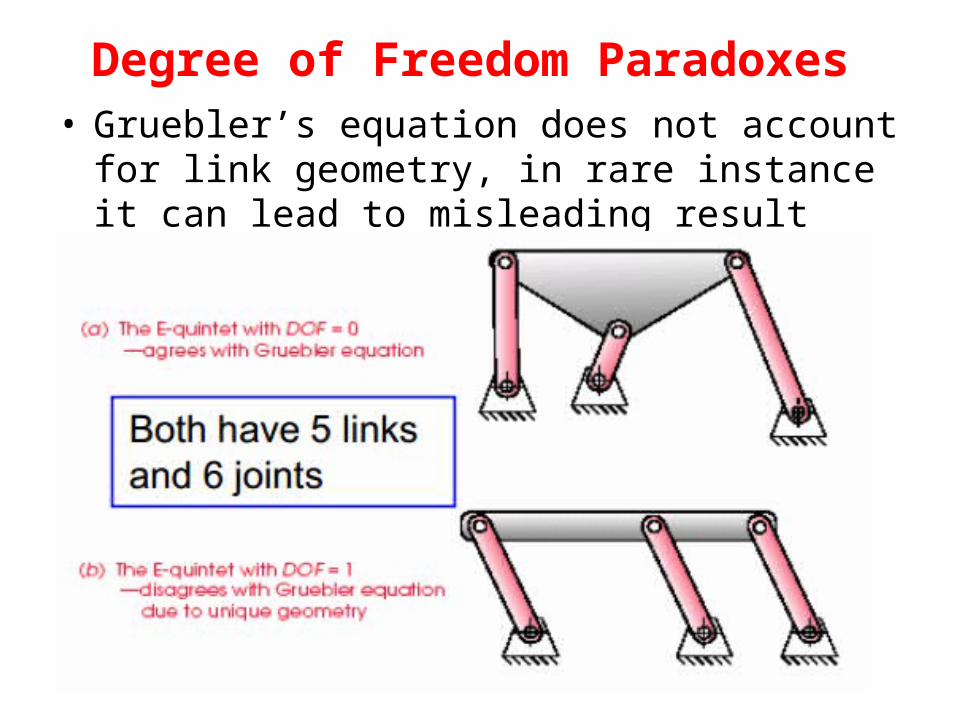
Degree of Freedom Paradoxes• Gruebler’s equation does not account for link
geometry, in rare instance it can lead to misleading result
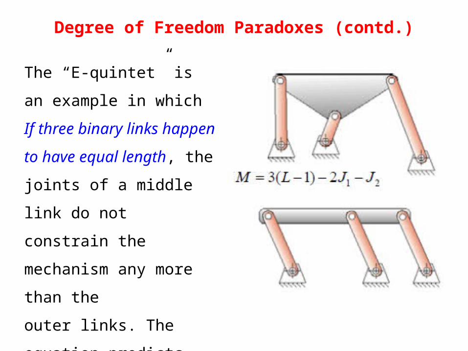
Degree of Freedom Paradoxes (contd.)
The “E-quintet” is an example
in which If three binary links
happen to have equal length,
the joints of a middle link do
not constrain the mechanism
any more than the
outer links. The equation
predicts DOF = 0, but the
mechanism has DOF = 1.
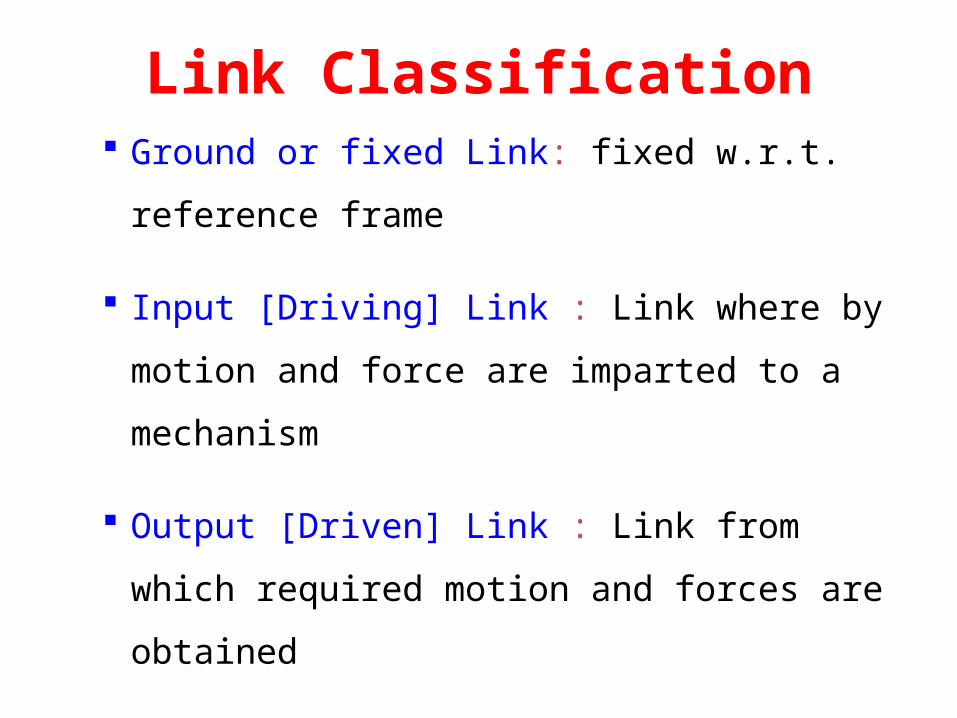
Link Classification Ground or fixed Link: fixed w.r.t. reference
frame
Input [Driving] Link : Link where by motion
and force are imparted to a mechanism
Output [Driven] Link : Link from which
required motion and forces are obtained
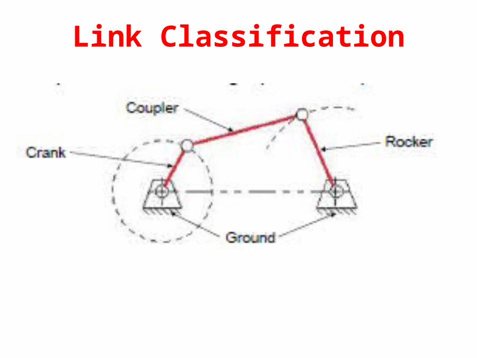
Link Classification
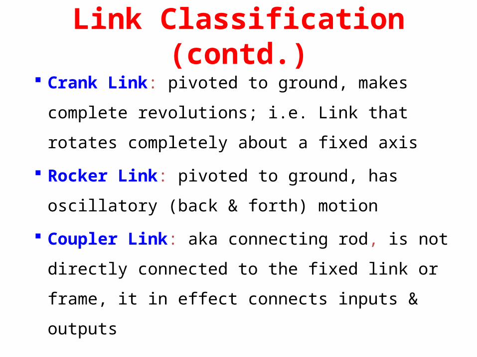
Link Classification (contd.) Crank Link: pivoted to ground, makes complete
revolutions; i.e. Link that rotates completely about a
fixed axis
Rocker Link: pivoted to ground, has oscillatory
(back & forth) motion
Coupler Link: aka connecting rod, is not directly
connected to the fixed link or frame, it in effect
connects inputs & outputs
Four Bar Mechanism
• Four bar mechanism consists of four rigid
links connected in a loop by four one degree
of freedom joints.
• A joint may be either a revolute, that is a
hinged joint, denoted by R, or a prismatic, as
sliding joint, denoted by P.
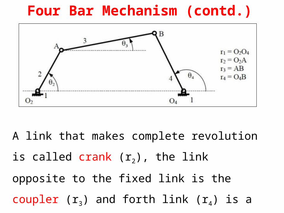
Four Bar Mechanism (contd.)
A link that makes complete revolution is called crank
(r2), the link opposite to the fixed link is the coupler (r3)
and forth link (r4) is a rocker if oscillates or another
crank if rotates.
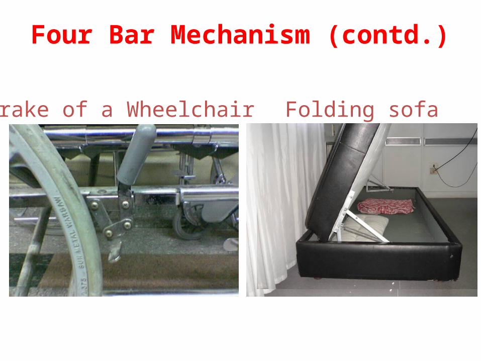
Brake of a Wheelchair Folding sofa
Four Bar Mechanism (contd.)

Four Bar Mechanism (contd.)
Backhoe Excavator
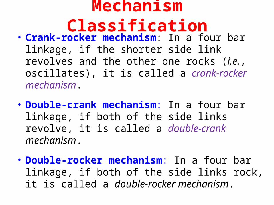
• Crank-rocker mechanism: In a four bar linkage, if the shorter side link revolves and the other one rocks (i.e., oscillates), it is called a crank-rocker mechanism.
• Double-crank mechanism: In a four bar linkage, if both of the side links revolve, it is called a double-crank mechanism.
• Double-rocker mechanism: In a four bar linkage, if both of the side links rock, it is called a double-rocker mechanism.
Mechanism Classification
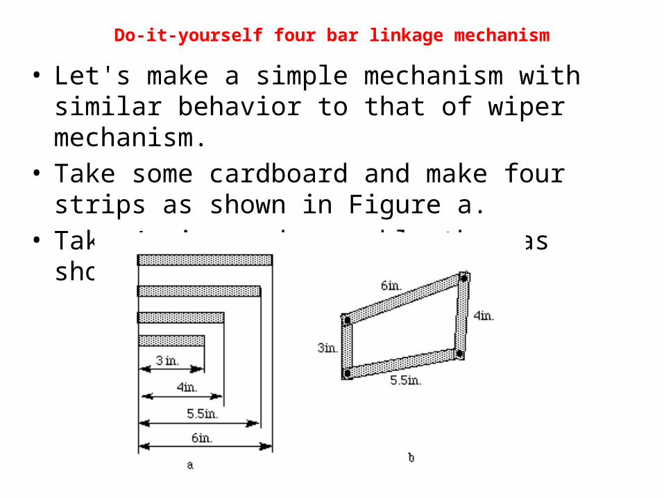
Do-it-yourself four bar linkage mechanism
• Let's make a simple mechanism with similar behavior to that of wiper mechanism.
• Take some cardboard and make four strips as shown in Figure a.
• Take 4 pins and assemble them as shown in Figure b.
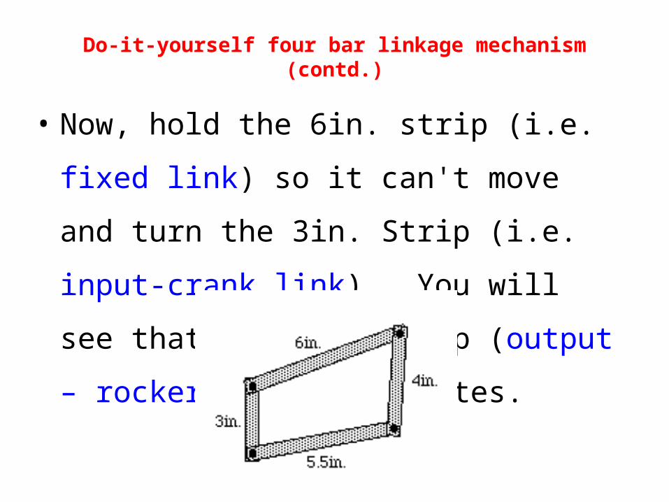
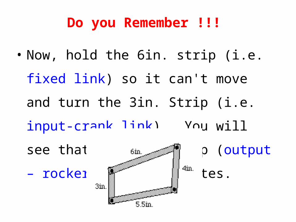
• Now, hold the 6in. strip (i.e. fixed link) so it
can't move and turn the 3in. Strip (i.e. input-
crank link) . You will see that the 4in. strip
(output – rocker link) oscillates.
Do-it-yourself four bar linkage mechanism (contd.)
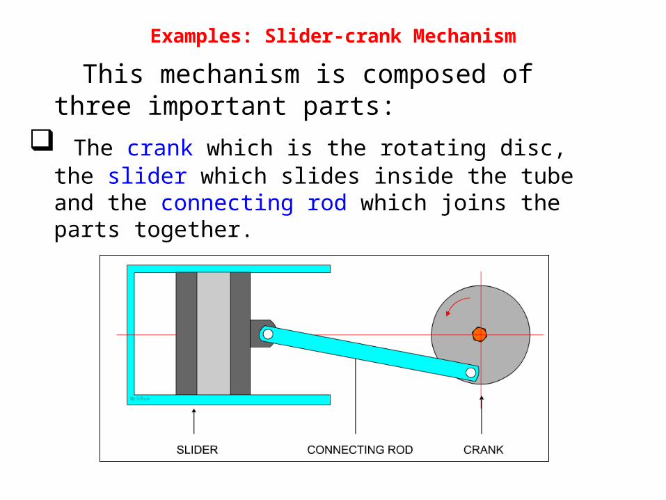
Examples: Slider-crank Mechanism
This mechanism is composed of three important parts:
The crank which is the rotating disc, the slider which slides inside the tube and the connecting rod which joins the parts together.
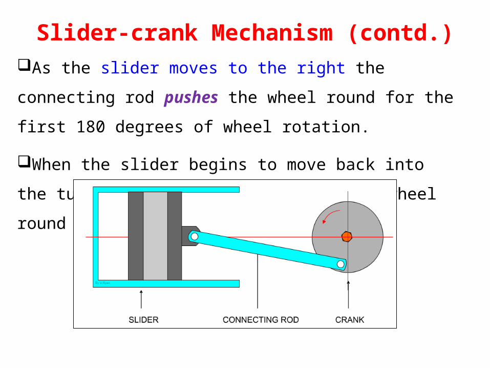
As the slider moves to the right the connecting rod pushes the
wheel round for the first 180 degrees of wheel rotation.
When the slider begins to move back into the tube, the
connecting rod pulls the wheel round to complete the rotation.
Animation : http://www.technologystudent.com/cams/crkslid1.htm
Slider-crank Mechanism (contd.)
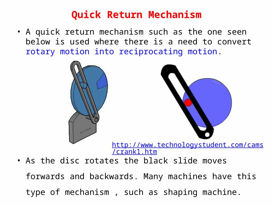
Quick Return Mechanism
• A quick return mechanism such as the one seen below is used where there is a need to convert rotary motion into reciprocating motion.
• As the disc rotates the black slide moves forwards and
backwards. Many machines have this type of mechanism , such
as shaping machine.
http://www.technologystudent.com/cams/crank1.htm
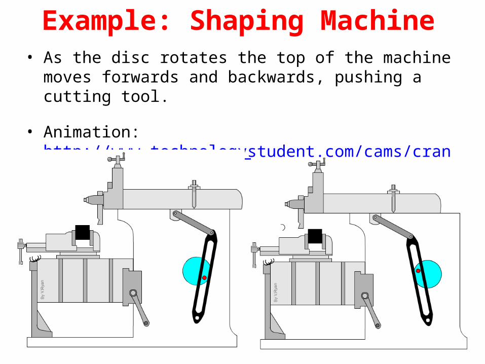
Example: Shaping Machine• As the disc rotates the top of the machine moves forwards
and backwards, pushing a cutting tool.
• Animation: http://www.technologystudent.com/cams/crank2.htm
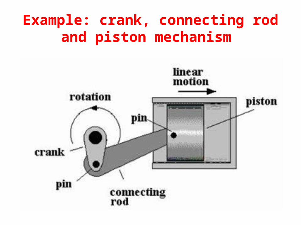
Example: crank, connecting rod and piston mechanism
• If the crank is turned, angular motion is converted into linear motion of the piston and input torque is transformed into force on the piston.
• If the piston is forced to move, the linear motion is converted into rotary motion and the force into torque.
• Thus, the crank and connecting rod are connected via a revolute joint, whereas connecting rod and piston are connected via a prismatic joint.
Example: crank, connecting rod and piston mechanism (contd.)
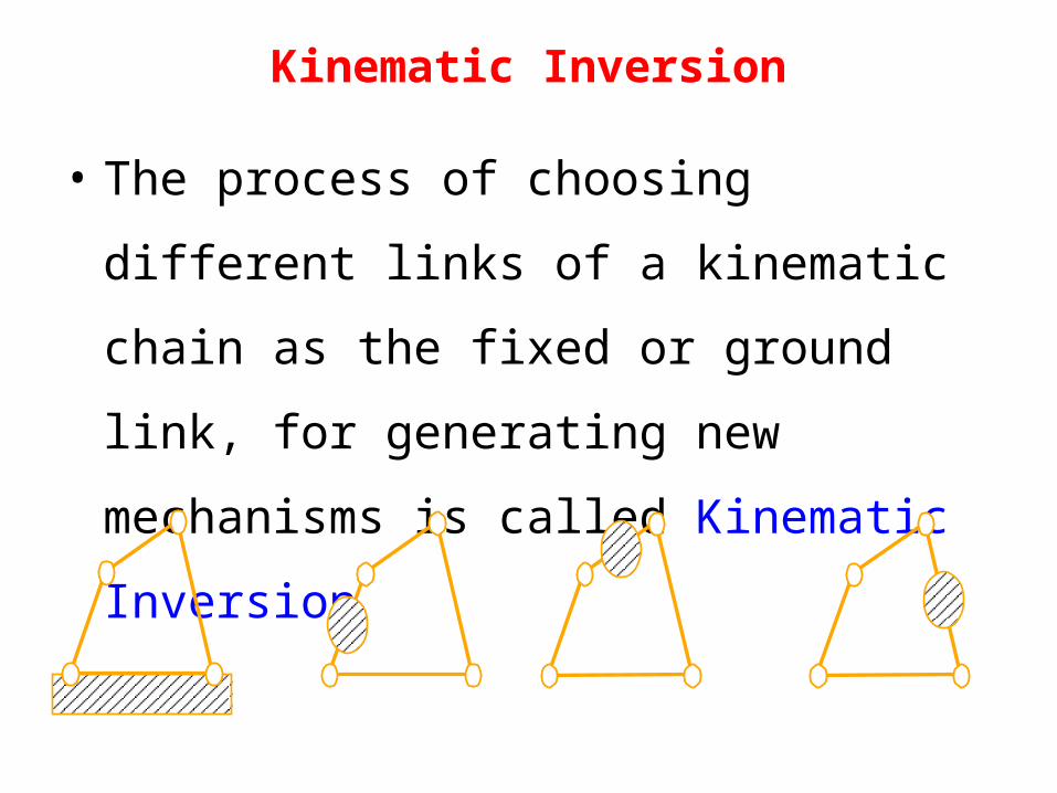
Kinematic Inversion
• The process of choosing different links of a
kinematic chain as the fixed or ground link, for
generating new mechanisms is called
Kinematic Inversion
Kinematic Inversion (contd.)
• Thus there are as many inversions of a given linkage
as it has links.
• It should be noted that, the relative motion b/w
various links are not altered, but their absolute
motions (those measured w.r.t. fixed link) may
change dramatically.
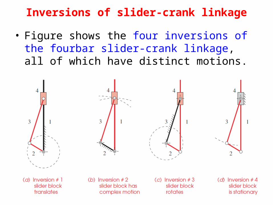
Inversions of slider-crank linkage• Figure shows the four inversions of the
fourbar slider-crank linkage, all of which have distinct motions.
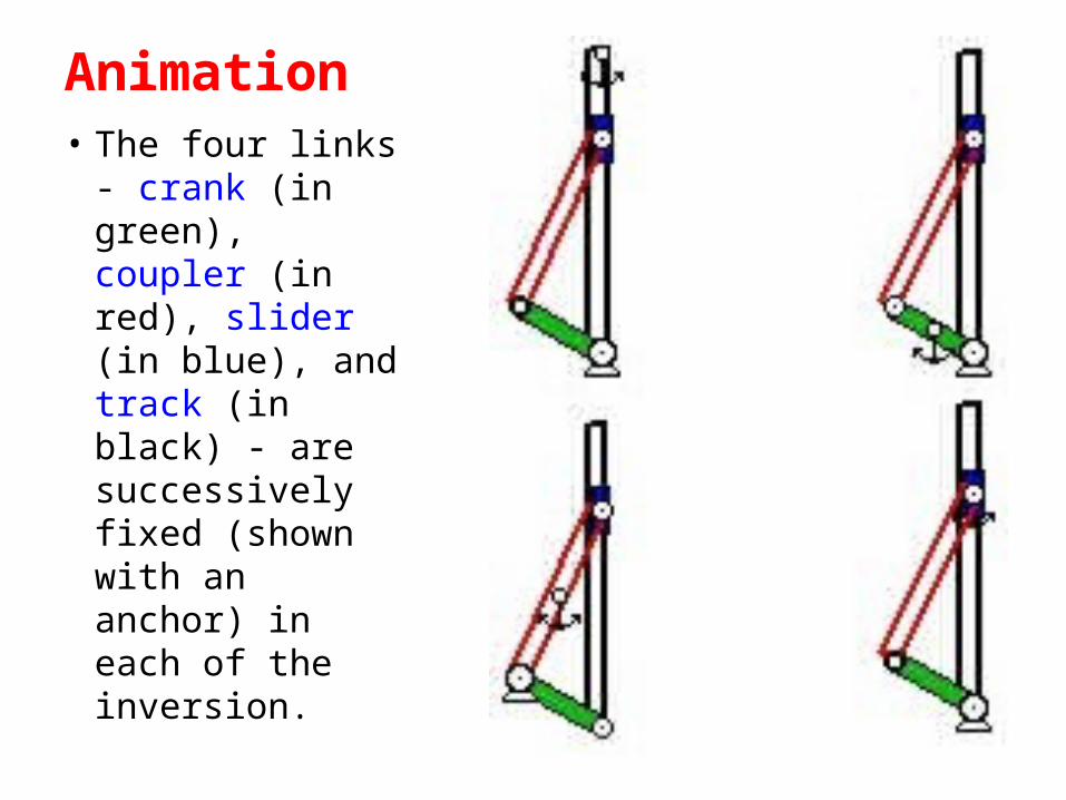
Animation• The four links -
crank (in green), coupler (in red), slider (in blue), and track (in black) - are successively fixed (shown with an anchor) in each of the inversion.
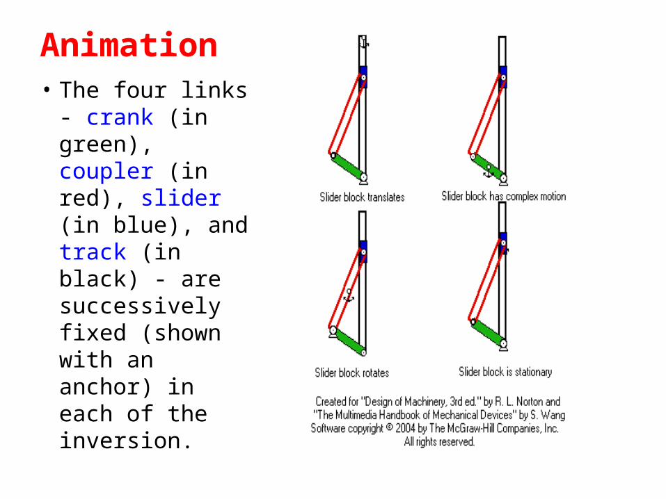
Animation• The four links -
crank (in green), coupler (in red), slider (in blue), and track (in black) - are successively fixed (shown with an anchor) in each of the inversion.
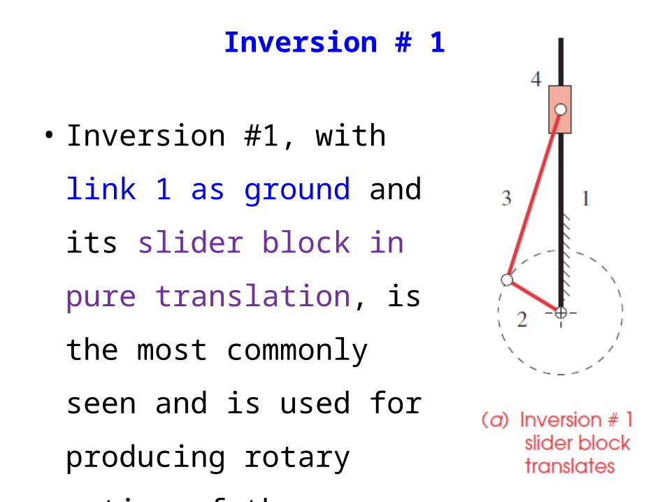
Inversion # 1
• Inversion #1, with link 1 as
ground and its slider block in
pure translation, is the most
commonly seen and is used
for producing rotary motion
of the wheels, crank etc.
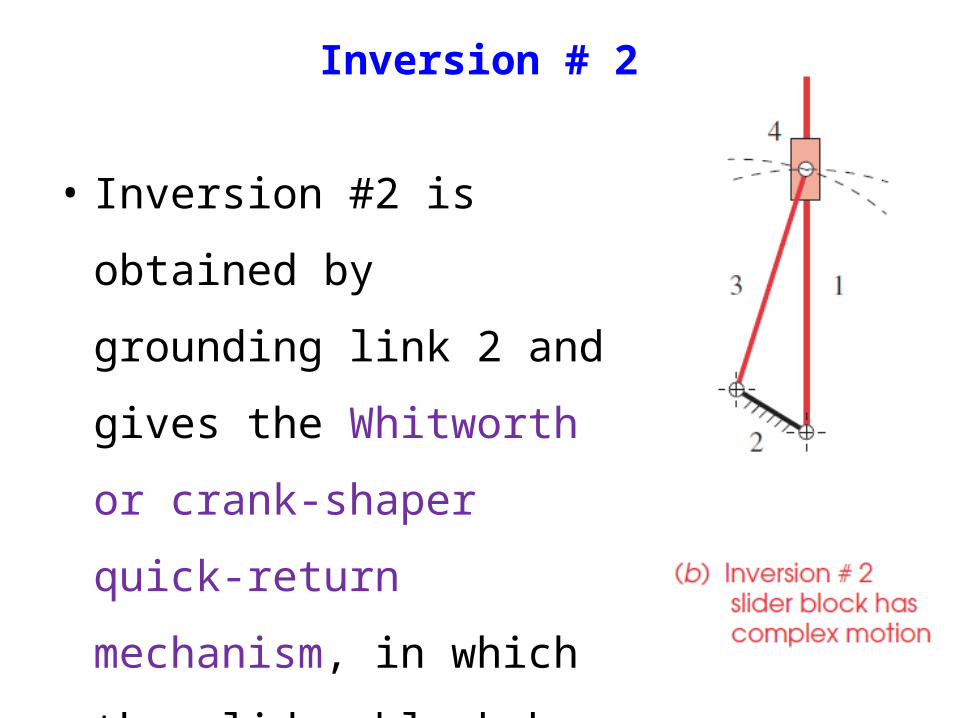
Inversion # 2
• Inversion #2 is obtained by
grounding link 2 and gives
the Whitworth or crank-
shaper quick-return
mechanism, in which the
slider block has complex
motion.
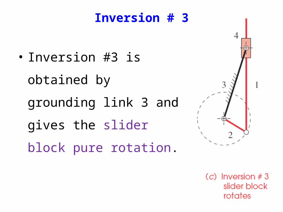
Inversion # 3
• Inversion #3 is obtained by
grounding link 3 and gives
the slider block pure
rotation.
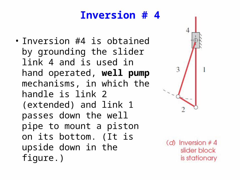
Inversion # 4
• Inversion #4 is obtained by grounding the slider link 4 and is used in hand operated, well pump mechanisms, in which the handle is link 2 (extended) and link 1 passes down the well pipe to mount a piston on its bottom. (It is upside down in the figure.)
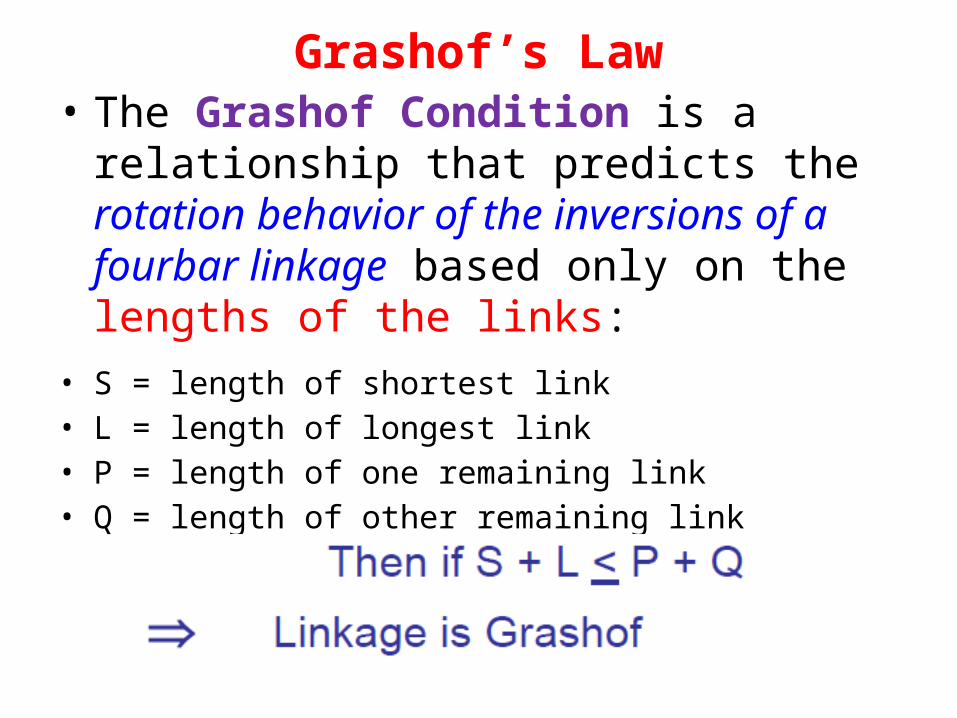
Grashof’s Law• The Grashof Condition is a relationship that
predicts the rotation behavior of the inversions of a fourbar linkage based only on the lengths of the links:
• S = length of shortest link• L = length of longest link• P = length of one remaining link• Q = length of other remaining link

Grashof’s Law (contd.)
If S+L ≤ P+Q the linkage is Grashof :at least
one link is capable of making a complete
revolution
Otherwise the linkage is non-Grashof : no
link is capable of making a complete revolution
• Now, hold the 6in. strip (i.e. fixed link) so it
can't move and turn the 3in. Strip (i.e. input-
crank link) . You will see that the 4in. strip
(output – rocker link) oscillates.
Do you Remember !!!
• It should be noted that nothing in Grashof's law specifies the order in which the links are to be connected or which link of the four-bar chain is fixed.
• That is, the determination of the Grashof’s condition can be made on a set of unassembled links.
• Whether they are later assembled into a kinematic chain in S, L, P, Q, or S, P, L, Q or any other order, will not change the Grashof’s condition.
Grashof’s Law (contd.)
• We are free, therefore to fix or ground any of the four
links.
• When we do so, we create the four inversions of the
four linkage illustrated in next slide.
• The motions possible from a fourbar linkage will
depend on both the Grashof condition and the
inversion chosen. The inversions will be defined with
respect to the shortest link.
Grashof’s Law (contd.)
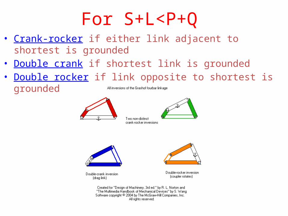
For S+L<P+Q• Crank-rocker if either link adjacent to shortest is grounded• Double crank if shortest link is grounded• Double rocker if link opposite to shortest is grounded
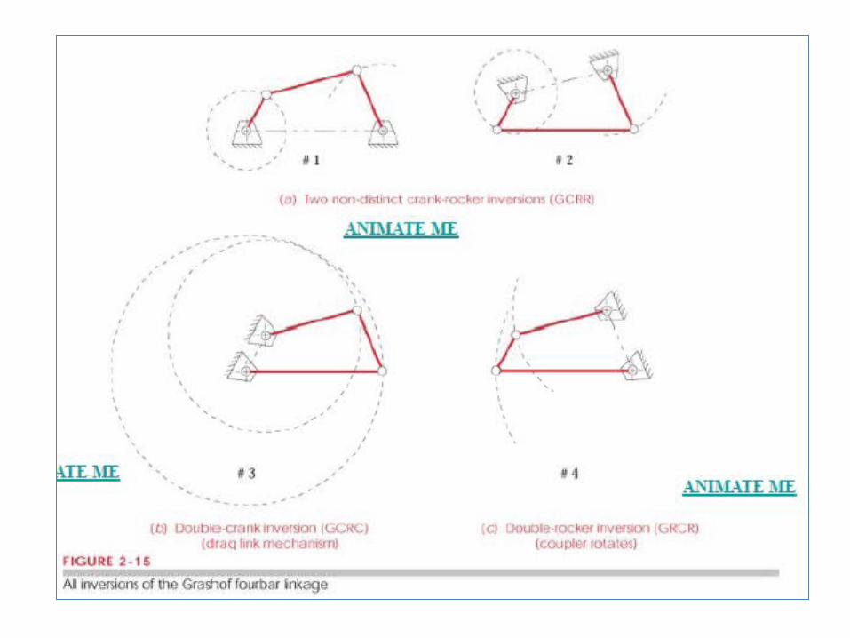
• All of these (inversions shown on previous
slide) fit Grashof's law, and in each the link s
makes complete revolution relative to the
other links.
• The different inversions are distinguished by
the location of the link s relative to the fixed
link.
Grashof’s Law (contd.)
If we pay attention !!
• There are as many inversions as links, but not
all inversions will have distinct motions.
• For example, a Grashof Fourbar has only 3
distinct inversions, 2 crank-rockers, 1 double-
crank, and 1 double-rocker as shown in earlier
slide.

For S+L > P+Q• All inversions will be double rockers• No link can fully rotate
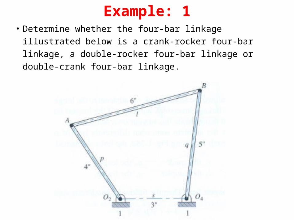
Example: 1• Determine whether the four-bar linkage illustrated
below is a crank-rocker four-bar linkage, a double-rocker four-bar linkage or double-crank four-bar linkage.
Example: 1 (contd.)
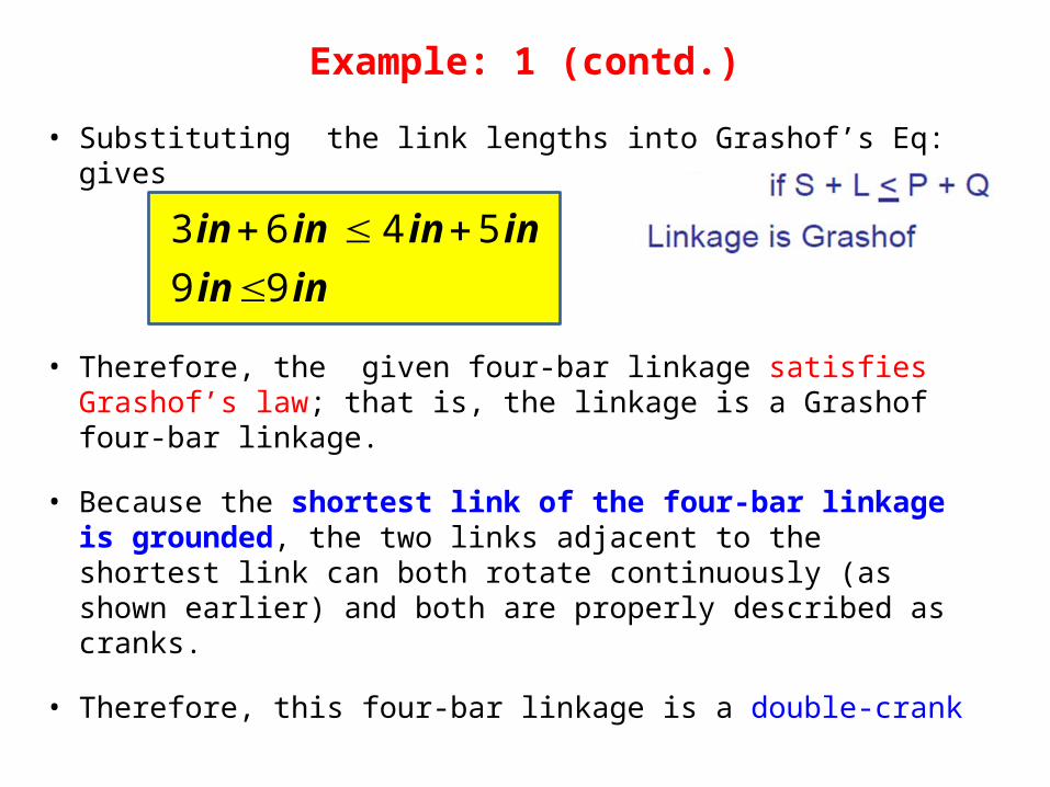
• Substituting the link lengths into Grashof’s Eq: gives
• Therefore, the given four-bar linkage satisfies Grashof’s law; that is, the linkage is a Grashof four-bar linkage.
• Because the shortest link of the four-bar linkage is grounded, the two links adjacent to the shortest link can both rotate continuously (as shown earlier) and both are properly described as cranks.
• Therefore, this four-bar linkage is a double-crank
inin
inininin
9 9
5 4 6 3
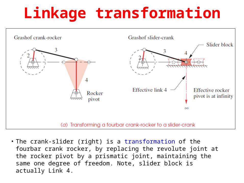
Linkage transformation
• The crank-slider (right) is a transformation of the fourbar crank rocker, by replacing the revolute joint at the rocker pivot by a prismatic joint, maintaining the same one degree of freedom. Note, slider block is actually Link 4.
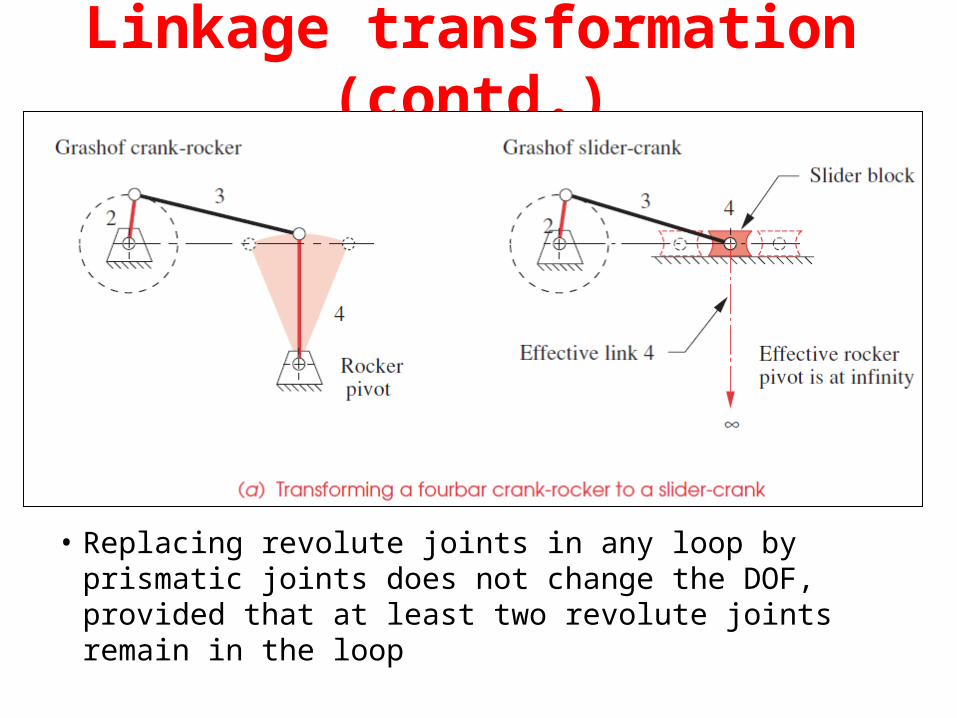
• Replacing revolute joints in any loop by prismatic joints does not change the DOF, provided that at least two revolute joints remain in the loop
Linkage transformation (contd.)