Embed Size (px)
Citation preview

ME 208 DYNAMICS
Dr. Ergin TÖNÜK
Department of Mechanical Engineering
Graduate Program of Biomedical Engineering
http://tonuk.me.metu.edu.tr

5/163 (4th), 5/168 (5th), 5/178 (6th), 5/176 (7th), 5/179 (8th)
For the instant represented, link CB is rotating
counterclockwise at a constant rate N = 4 rad/s, and its pin
A causes a clockwise rotation of the slotted member ODE.
Determine the angular velocity and angular acceleration
of ODE for this instant.
Assume a point P fixed on body ODE instantly
coincident with A.
Ԧ𝑣𝑃 = Ԧ𝑣𝐴 + Ԧ𝑣𝑃/𝐴Ԧ𝑣𝑃 = 𝜔𝑂𝐷𝐸 × Ԧ𝑟𝑃/𝑂 = 𝜔𝑂𝐷𝐸
𝑘 × 0.12 Ƹ𝑖 = 0.12𝜔𝑂𝐷𝐸 Ƹ𝑗
Ԧ𝑣𝐴 = 𝑁𝑘 × Ԧ𝑟𝐴/𝐶 = 4𝑘 × −0.12 Ƹ𝑗 = 0.48 Ƹ𝑖 𝑚/𝑠
Ԧ𝑣𝑃/𝐴 = 𝑣𝑃/𝐴 𝑐𝑜𝑠45° Ƹ𝑖 + 𝑠𝑖𝑛45° Ƹ𝑗
0.12𝜔𝑂𝐷𝐸 Ƹ𝑗 = 0.48 Ƹ𝑖 + 𝑣𝑃/𝐴 𝑐𝑜𝑠45° Ƹ𝑖 + 𝑠𝑖𝑛45° Ƹ𝑗
Ƹ𝑖: 0 = 0.48 + 𝑣𝑃/𝐴𝑐𝑜𝑠45°, 𝑣𝑃/𝐴 = −0.679 𝑚/𝑠
Ƹ𝑗: 0.12𝜔𝑂𝐷𝐸 = 𝑣𝑃/𝐴𝑠𝑖𝑛45°, 𝜔𝑂𝐷𝐸 = −4 𝑟𝑎𝑑/𝑠
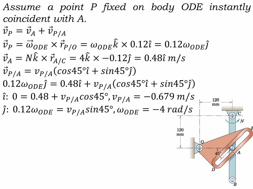
Assume a point P fixed on body ODE instantly
coincident with A.Ԧ𝑎𝑃 = Ԧ𝑎𝐴 + Ԧ𝑎𝑃/𝐴Ԧ𝑎𝑃 = Ԧ𝑎𝑃𝑡 + Ԧ𝑎𝑃𝑛Ԧ𝑎𝑃 = Ԧ𝛼𝑂𝐷𝐸 × Ԧ𝑟𝑃/𝑂 − 𝜔𝑂𝐷𝐸
2 Ԧ𝑟𝑃/𝑂Ԧ𝑎𝑃 = 𝛼𝑂𝐷𝐸 𝑘 × 0.12 Ƹ𝑖 − 42 ∗ 0.12 Ƹ𝑖Ԧ𝑎𝑃 = −1.920 Ƹ𝑖 + 0.12𝛼𝑂𝐷𝐸 Ƹ𝑗 𝑚/𝑠2
Ԧ𝑎𝐴 = Ԧ𝑎𝐴𝑡 + Ԧ𝑎𝐴𝑛 = Ԧ𝛼𝐶𝐴 × Ԧ𝑟𝐴/𝐶 −𝑁2 Ԧ𝑟𝐴/𝐶
Ԧ𝑎𝐴 = 0 × −0.12 Ƹ𝑗 − 42 ∗ −0.12 Ƹ𝑗 = 1.920 Ƹ𝑗 𝑚/𝑠2
Ԧ𝑎𝑃/𝐴 = 2𝜔𝑂𝐷𝐸 × Ԧ𝑣𝑃/𝐴 + Ԧ𝑎𝑟𝑒𝑙Ԧ𝑎𝑃/𝐴 = 2 ∗ −4𝑘 × −0.679 𝑐𝑜𝑠45° Ƹ𝑖 + 𝑠𝑖𝑛45° Ƹ𝑗 + 𝑎𝑟𝑒𝑙 𝑐𝑜𝑠45° Ƹ𝑖 + 𝑠𝑖𝑛45° Ƹ𝑗
Ԧ𝑎𝑃/𝐴 = 3.84 − Ƹ𝑖 + Ƹ𝑗 + 𝑎𝑟𝑒𝑙 𝑐𝑜𝑠45° Ƹ𝑖 + 𝑠𝑖𝑛45° Ƹ𝑗−1.92 Ƹ𝑖 + 0.12𝛼𝑂𝐷𝐸 Ƹ𝑗 = 1.92 Ƹ𝑗 + 3.84 − Ƹ𝑖 + Ƹ𝑗 + 𝑎𝑟𝑒𝑙 𝑐𝑜𝑠45° Ƹ𝑖 + 𝑠𝑖𝑛45° Ƹ𝑗
Ƹ𝑖: −1.92 = −3.84 + 𝑎𝑟𝑒𝑙𝑐𝑜𝑠45°𝑎𝑟𝑒𝑙 = 2.72 𝑚/𝑠2
Ƹ𝑗: 0.12𝛼𝑂𝐷𝐸 = 1.92 + 3.84 + 2.72𝑠𝑖𝑛45°𝛼𝑂𝐷𝐸 = 64.0 𝑟𝑎𝑑/𝑠2

Plane Kinetics of Rigid BodiesChapter 4: Kinetics of Systems of Particles
4/1 IntroductionSince a rigid body is assumed to be a continuous collection of
infinitely many particles of infinitesimal mass (continuum
approximation) with no change in the relative positions of
particles, the kinetic equations are derived using a general
system of particles (rigid or deformable or even flowing) in our
textbook. This approach is very general and when the rigidity
condition is imposed the equations will simplify to what we
will be using in Chapter 6 for kinetics of rigid bodies.

4/2 Generalized Newton’s Second Law
For a system of particles in a
volume, let Ԧ𝐹𝑖 be the
resultant of forces acting on
a particle 𝑚𝑖 due to sources
external to the system
boundary whereas Ԧ𝑓𝑖 be the
resultant of forces on 𝑚𝑖 due
to sources within the system
boundary. Newton’s second
law for the particle i is then:
Ԧ𝐹𝑖 + Ԧ𝑓𝑖 = 𝑚𝑖 Ԧ𝑎𝑖

Now recall the definition of
mass center (center of mass)
from statics:
𝑚Ԧ𝑟𝐺 =
𝑖=1
𝑛
𝑚𝑖 Ԧ𝑟𝑖 = න𝑚
Ԧ𝑟 𝑑𝑚
where
𝑚 =
𝑖=1
𝑛
𝑚𝑖 = න𝑚
𝑑𝑚
Second time derivative of this
equation yields
𝑚 ሷԦ𝑟𝐺 =
𝑖=1
𝑛
𝑚𝑖ሷԦ𝑟𝑖 =
𝑖=1
𝑛
𝑚𝑖 Ԧ𝑎𝑖

𝑖=1
𝑛
Ԧ𝐹𝑖 + Ԧ𝑓𝑖 =
𝑖=1
𝑛
𝑚𝑖 Ԧ𝑎𝑖 = 𝑚 ሷԦ𝑟𝐺 = 𝑚Ԧ𝑎𝐺
However when summed up within the
system boundary, due to Newton’s third
law, the action-reaction principle,
𝑖=1
𝑛
Ԧ𝑓𝑖 = 0
This leads to the principle of motion of
center of mass:
𝑖=1
𝑛
Ԧ𝐹𝑖 = 𝑚 Ԧ𝑎𝐺
which states that the acceleration of
center of mass of the system of particles
is in the same direction with the
resultant external force and is inversely
proportional with the total mass of the
system of particles. Please note that the
line of action of resultant of external
forces need not pass through the mass
center, G.

𝑖=1
𝑛
Ԧ𝐹𝑖 = 𝑚 Ԧ𝑎𝐺
This vector equation may be
resolved in any convenient
coordinate system:
x-y,
n-t,
r-.
This is sufficient for rigid
bodies.

4/3 Work-Energy
For a particle of mass 𝑚𝑖 the work-energy relation:
𝑈𝑖 = ∆𝑇𝑖 + ∆𝑉𝑔𝑖+ ∆𝑉𝑒𝑖
The work done by internal forces cancel each other
because for a rigid body the action and reaction
pairs have identical displacements therefore the
work done only by the external forces need to be
considered during summation. However for non-
rigid bodies displacements of action reaction pairs
may be different causing storage of elastic potential
energy or dissipation of mechanical energy which
we will not discuss in this course.
𝑖=1
𝑛
𝑈𝑖 =
𝑖=1
𝑛
∆𝑇𝑖 +
𝑖=1
𝑛
∆𝑉𝑔𝑖+
𝑖=1
𝑛
∆𝑉𝑒𝑖

For the system
𝑈1→2 = ∆𝑇 + ∆𝑉𝑔 + ∆𝑉𝑒 where 𝑈1→2 contains only the
work done by external forces.
∆𝑇 =
𝑖=1
𝑛1
2𝑚𝑖𝑣𝑖
2
Ԧ𝑣𝑖 = Ԧ𝑣𝐺 +ሶԦ𝜌𝑖
𝑣𝑖2 = Ԧ𝑣𝑖 ∙ Ԧ𝑣𝑖 = Ԧ𝑣𝐺 +
ሶԦ𝜌𝑖 ∙ Ԧ𝑣𝐺 +ሶԦ𝜌𝑖 = 𝑣𝐺
2 + ሶ𝜌𝑖2 + 2 Ԧ𝑣𝐺 ∙
ሶԦ𝜌𝑖Substitution into kinetic energy expression yields
∆𝑇 =
𝑖=1
𝑛1
2𝑚𝑖𝑣𝐺
2 +
𝑖=1
𝑛1
2𝑚𝑖 ሶ𝜌𝑖
2 +
𝑖=1
𝑛
𝑚𝑖 Ԧ𝑣𝐺 ∙ሶԦ𝜌𝑖
∆𝑇 =1
2𝑚𝑣𝐺
2 +
𝑖=1
𝑛1
2𝑚𝑖 ሶ𝜌𝑖
2 + Ԧ𝑣𝐺 ∙
𝑖=1
𝑛
𝑚𝑖ሶԦ𝜌𝑖

∆𝑇 =1
2𝑚𝑣𝐺
2 +
𝑖=1
𝑛1
2𝑚𝑖 ሶ𝜌𝑖
2 + Ԧ𝑣𝐺 ∙
𝑖=1
𝑛
𝑚𝑖ሶԦ𝜌𝑖
but
𝑖=1
𝑛
𝑚𝑖 Ԧ𝜌𝑖 = 0
(definition of mass center so its time derivative is
zero too!)
∆𝑇 =1
2𝑚𝑣𝐺
2 +
𝑖=1
𝑛1
2𝑚𝑖 ሶ𝜌𝑖
2
The first term is translational kinetic energy of the
mass center, G, the second term is due to relative
motion of particles with respect to the mass center,
G.

4/4 Impulse Momentum
Linear MomentumԦ𝐺𝑖 = 𝑚𝑖 Ԧ𝑣𝑖
Ԧ𝐺 =
𝑖=1
𝑛
Ԧ𝐺𝑖 =
𝑖=1
𝑛
𝑚𝑖 Ԧ𝑣𝑖 =
𝑖=1
𝑛
𝑚𝑖 Ԧ𝑣𝐺 +ሶԦ𝜌𝑖
Ԧ𝐺 =
𝑖=1
𝑛
𝑚𝑖 Ԧ𝑣𝐺 +𝑑
𝑑𝑡
𝑖=1
𝑛
𝑚𝑖 Ԧ𝜌𝑖 = Ԧ𝑣𝐺
𝑖=1
𝑛
𝑚𝑖 + 0 = 𝑚 Ԧ𝑣𝐺
ሶԦ𝐺 =𝑑 Ԧ𝐺
𝑑𝑡=
𝑑
𝑑𝑡𝑚 Ԧ𝑣𝐺 = 𝑚 Ԧ𝑎𝐺 = Ԧ𝐹
This is valid for constant mass ( ሶ𝑚 = 0) systems.

Angular Momentum
• Angular Momentum about a Fixed Point O
𝐻𝑂 =
𝑖=1
𝑛
Ԧ𝑟𝑖 ×𝑚𝑖 Ԧ𝑣𝑖
ሶ𝐻𝑂 =
𝑖=1
𝑛
ሶԦ𝑟𝑖 ×𝑚𝑖 Ԧ𝑣𝑖 +
𝑖=1
𝑛
Ԧ𝑟𝑖 ×𝑚𝑖ሶԦ𝑣𝑖 = 0 +
𝑖=1
𝑛
Ԧ𝑟𝑖 ×𝑚𝑖 Ԧ𝑎𝑖
ሶ𝐻𝑂 =
𝑖=1
𝑛
Ԧ𝑟𝑖 × Ԧ𝐹𝑖 =
𝑖=1
𝑛
𝑀𝑂
According to Varignon’s principle sum of moments
of forces is equal to the moment of the resultant of
the forces.

Angular Momentum
• Angular Momentum about Mass Center G
𝐻𝐺 =
𝑖=1
𝑛
Ԧ𝜌𝑖 ×𝑚𝑖 Ԧ𝑣𝑖 , Ԧ𝑣𝑖 = Ԧ𝑣𝐺 +ሶԦ𝜌𝑖
𝐻𝐺 =
𝑖=1
𝑛
Ԧ𝜌𝑖 ×𝑚𝑖 Ԧ𝑣𝐺 +ሶԦ𝜌𝑖 = − Ԧ𝑣𝐺 ×
𝑖=1
𝑛
𝑚𝑖 Ԧ𝜌𝑖 +
𝑖=1
𝑛
Ԧ𝜌𝑖 ×𝑚𝑖ሶԦ𝜌𝑖 = 0 +
𝑖=1
𝑛
Ԧ𝜌𝑖 ×𝑚𝑖ሶԦ𝜌𝑖
ሶ𝐻𝐺 =
𝑖=1
𝑛
ሶԦ𝜌𝑖 ×𝑚𝑖ሶԦ𝜌𝑖 +
𝑖=1
𝑛
Ԧ𝜌𝑖 ×𝑚𝑖ሷԦ𝜌𝑖 = 0 +
𝑖=1
𝑛
Ԧ𝜌𝑖 ×𝑚𝑖ሷԦ𝜌𝑖
Ԧ𝑎𝑖 = Ԧ𝑎𝐺 +ሷԦ𝜌𝑖 ,
ሷԦ𝜌𝑖 = Ԧ𝑎𝑖 − Ԧ𝑎𝐺
ሶ𝐻𝐺 =
𝑖=1
𝑛
Ԧ𝜌𝑖 ×𝑚𝑖 Ԧ𝑎𝑖 − Ԧ𝑎𝐺 =
𝑖=1
𝑛
Ԧ𝜌𝑖 ×𝑚𝑖 Ԧ𝑎𝑖 + Ԧ𝑎𝐺 ×
𝑖=1
𝑛
Ԧ𝜌𝑖𝑚𝑖 =
𝑖=1
𝑛
Ԧ𝜌𝑖 × Ԧ𝐹𝑖 + 0
According to Varignon’s theorem
ሶ𝐻𝐺 =𝑀𝐺

Angular Momentum
• Angular Momentum about an Arbitrary Point P
𝐻𝑃 =
𝑖=1
𝑛
𝜌′𝑖 ×𝑚𝑖 Ԧ𝑣𝑖
𝜌′𝑖 = Ԧ𝜌𝐺 + Ԧ𝜌𝑖
𝐻𝑃 =
𝑖=1
𝑛
Ԧ𝜌𝐺 + Ԧ𝜌𝑖 ×𝑚𝑖 Ԧ𝑣𝑖 = Ԧ𝜌𝐺 ×
𝑖=1
𝑛
𝑚𝑖 Ԧ𝑣𝑖 +
𝑖=1
𝑛
Ԧ𝜌𝑖 ×𝑚𝑖 Ԧ𝑣𝑖 = Ԧ𝜌𝐺 × Ԧ𝐺 + 𝐻𝐺
𝐻𝑃 = 𝐻𝐺 + Ԧ𝜌𝐺 × Ԧ𝐺One may write
𝑀𝑃 =𝑀𝐺 + Ԧ𝜌𝐺 × Ԧ𝐹
𝑀𝑃 =ሶ
𝐻𝐺 + Ԧ𝜌𝐺 ×𝑚 Ԧ𝑎𝐺
Moment about an arbitrary point is time rate of angular
momentum about mass center plus moment of 𝑚 Ԧ𝑎𝐺 about P.

4/5 Conservation of Energy and Momentum
• Conservation of EnergyA conservative system does not lose mechanical energy due
to internal friction or other types of inelastic forces. If no
work is done on a conservative system by external forces
then
𝑈1→2 = 0 = ∆𝑇 + ∆𝑉𝑔 + ∆𝑉𝑒• Conservation of MomentumIf for an interval of time
Ԧ𝐹 = 0,ሶԦ𝐺 = 0, ∆ Ԧ𝐺 = 0
Again for an interval of time if
𝑀𝐺 = 0, ሶ𝐻𝐺 = 0, ∆𝐻𝐺 = 0
𝑀𝑂 = 0, ሶ𝐻𝑂 = 0, ∆𝐻𝑂 = 0
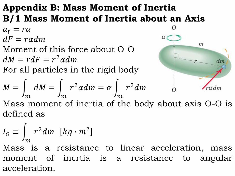
Appendix B: Mass Moment of Inertia
B/1 Mass Moment of Inertia about an Axis𝑎𝑡 = 𝑟𝛼𝑑𝐹 = 𝑟𝛼𝑑𝑚Moment of this force about O-O
𝑑𝑀 = 𝑟𝑑𝐹 = 𝑟2𝛼𝑑𝑚For all particles in the rigid body
𝑀 = න𝑚
𝑑𝑀 = න𝑚
𝑟2𝛼𝑑𝑚 = 𝛼න𝑚
𝑟2𝑑𝑚
Mass moment of inertia of the body about axis O-O is
defined as
𝐼𝑂 ≡ න𝑚
𝑟2𝑑𝑚 𝑘𝑔 ∙ 𝑚2
Mass is a resistance to linear acceleration, mass
moment of inertia is a resistance to angular
acceleration.

For discrete system of particles
𝐼𝑂 =
𝑖=1
𝑛
𝑟𝑖2𝑚𝑖
For constant density (homogeneous) rigid bodies
𝐼𝑂 = 𝜌න𝑉
𝑟2𝑑𝑉
Radius of Gyration
𝑘𝑥 ≡𝐼𝑥𝑚, 𝐼𝑥 = 𝑘𝑥
2𝑚
Radius of gyration is a measure of mass
distribution of a rigid body about the axis. A
system with equivalent mass moment of inertia is
a very thin ring of same mass and radius kx.

Transfer of Axis (Parallel Axis Theorem)
𝐼𝑥 = 𝐼𝐺 +𝑚 𝑔𝑋 2
𝑘𝑥2 = 𝑘𝐺
2 + 𝑔𝑋 2
Composite Bodies
Mass moment of inertia of a composite body about
an axis is the sum of individual mass moments of
each part about the same axis (which may be
calculated utilizing parallel axis theorem if mass
moment of inertia of each part is known about its
mass center).

B/10 (4th), None (5th), B/14 (6th), None (7th), None (8th)
Calculate the mass moment of inertia about the axis O-O
for the steel disk with the hole.
𝐼𝑂 = 𝐼𝑂𝑠𝑜𝑙𝑖𝑑 − 𝐼𝑂ℎ𝑜𝑙𝑒For thin disks
𝐼𝐺 =1
2𝑚𝑟2
𝐼𝑂𝑠𝑜𝑙𝑖𝑑 = 𝐼𝐺 =1
2𝑚𝑟2 =
1
2𝜌𝜋𝑟𝑑
2𝑡𝑟𝑑2 = 2.96 𝑘𝑔.𝑚2
𝐼𝑂ℎ𝑜𝑙𝑒 = 𝐼𝐺 +𝑚𝑑2 =1
2𝑚𝑟2 +𝑚𝑑2 =
1
2𝜌𝜋𝑟ℎ
2𝑡𝑟ℎ2 + 𝜌𝜋𝑟ℎ
2𝑑2
= 0.348 𝑘𝑔.𝑚2
𝐼𝑂 = 2.96 − 0.348 = 2.61 𝑘𝑔.𝑚2
𝑘𝑂 =𝐼𝑂𝑚
=2.61
𝜌𝜋𝑟𝑑2𝑡 − 𝜌𝜋𝑟ℎ
2𝑡= 0.230 𝑚

Chapter 6: Plane Kinetics of Rigid Bodies
6/1 IntroductionIn this chapter we will deal with relations among external
forces and moments, and, translational and rotational
motions of rigid bodies in plane motion.
We will write two force and one moment equation (or
equivalent) for the plane motion of rigid bodies.
The equations derived in Chapter 4 will be simplified for a
rigid body and used. Kinematic relations developed in
Chapters 2 and 5 will be utilized.
Drawing correct free body diagrams is essential in
application of Force-Mass-Acceleration method. The other
two methods, similar to kinetics of particles are Work-
Energy and Impulse-Momentum.

A. Direct Application of Newton’s Second
Law – Force Mass Acceleration Method
for a Rigid Body
6/2 General Equations of Motion
Ԧ𝐹 =ሶԦ𝐺 = 𝑚 Ԧ𝑎𝐺
𝑀𝐺 =ሶ
𝐻𝐺 = 𝐼𝐺 Ԧ𝛼
These are known as Euler’s first and second laws.
By using statics information one may replace the forces on a
rigid body by a single resultant force passing through mass
center and a couple moment. The equivalent force causes linear
acceleration of the mass center in the direction of force, the
couple moment causes angular acceleration about the axis of the
couple moment.

Plane Motion Equations
Ԧ𝐹 = 𝑚 Ԧ𝑎𝐺
𝐻𝐺 =
𝑖=1
𝑛
Ԧ𝜌𝑖 ×𝑚𝑖ሶԦ𝜌𝑖 = න
𝑚
Ԧ𝜌 × ሶԦ𝜌𝑑𝑚
For a rigid body Ԧ𝜌𝑖 = 𝑐𝑜𝑛𝑠𝑡 thereforeሶԦ𝜌 = 𝜔 × Ԧ𝜌
Ԧ𝜌 × ሶԦ𝜌 = Ԧ𝜌 × 𝜔 × Ԧ𝜌 = − Ԧ𝜌 × Ԧ𝜌 × 𝜔 = 𝜌2𝜔
𝐻𝐺 = න𝑚
𝜌2𝜔𝑑𝑚 = 𝜔න𝑚
𝜌2𝑑𝑚 = 𝜔𝐼𝐺
For a rigid body IG is constant so ሶ
𝐻𝐺 = 𝐼𝐺ሶ𝜔 = 𝐼𝐺 Ԧ𝛼
Ԧ𝐹 = 𝑚 Ԧ𝑎𝐺 ,𝑀𝐺 = 𝐼𝐺 Ԧ𝛼

Ԧ𝐹 = 𝑚 Ԧ𝑎𝐺
𝑀𝐺 = 𝐼𝐺 Ԧ𝛼
Euler’s laws of motion, generalization of Newton’s second
law for particles to rigid bodies approximately 50 years
after Newton.
For plane motion the force equation may be resolved in x-y,
n-t or r- coordinates whichever is suitable. For moment
equation it is always normal to the plane of motion
therefore can be expressed in scalar form as CCW or CW.
The moment equation has an alternative derivation yielding
the same result. Please go over it in the textbook.

Alternative Moment Equation
Sometimes it may be more convenient to take moment
about another point rather than the mass center G. In
that case
𝑀𝑃 =ሶ
𝐻𝐺 + Ԧ𝜌𝐺 ×𝑚 Ԧ𝑎𝐺 , Ԧ𝜌𝐺 = 𝑃𝐺
This equation can be written as
𝑀𝑃 = 𝐼𝐺𝛼 +𝑀𝑜𝑚𝑒𝑛𝑡 𝑜𝑓 𝑚 Ԧ𝑎𝐺 𝑎𝑏𝑜𝑢𝑡 𝑃
If point P is a fixed point (like the axis of rotation) then
𝑀𝑂 = 𝐼𝐺𝛼 +𝑀𝑜𝑚𝑒𝑛𝑡 𝑜𝑓 𝑚 Ԧ𝑎𝐺 𝑎𝑏𝑜𝑢𝑡 𝑃, 𝑎𝐺𝑡 = 𝑂𝐺 𝛼,
𝑀𝑜𝑚𝑒𝑛𝑡 𝑜𝑓 𝑚 Ԧ𝑎𝐺 𝑎𝑏𝑜𝑢𝑡 𝑃 = 𝑂𝐺 2𝛼
𝑀𝑂 = 𝐼𝐺𝛼 + 𝑂𝐺 2𝑚𝛼 = 𝐼𝐺 +𝑚 𝑂𝐺 2 𝛼 = 𝐼𝑂𝛼

In unconstrained motion the two components of
acceleration of the mass center and angular acceleration
are independent of each other as in the case of a rocket.
In constrained motion due to kinematic restrictions there
are relations among two components of the acceleration of
mass center and the angular acceleration of the body.
Therefore these kinematic constraint equations have to be
determined using methods developed in Chapter 5. There
are also reaction forces due to constraints in the direction
of restricted motions which should be included in the free
body diagram.

Analysis Procedure
Kinematics: Determine Ԧ𝑣𝐺 , Ԧ𝑎𝐺 , and (or the
kinematic relations among them) if possible.
Diagrams: Draw proper free body and kinetic
diagrams.
Equations of motion: Any force or acceleration in
the direction of positive coordinate is positive.
Count the number of available independent
equations and number of unknowns to be
determined.