Embed Size (px)
Citation preview

Part Number MN-MDX420 Revision 6
Comtech EF Data is an AS9100 Rev B / ISO9001:2000 Registered Company
IMPORTANT NOTE: The information in this document supersedes all previously published information for this product. This manual is subject to change without notice.
MDX420 SkyWire™ Satellite Network Gateway
Installation and Operation Manual


Copyright © 2013 Comtech EF Data. All rights reserved. Printed in the USA. Comtech EF Data, 2114 West 7th Street, Tempe, Arizona 85281 USA, 480.333.2200, FAX: 480.333.2161
Comtech EF Data is an AS9100 Rev B / ISO9001:2000 Registered Company
MDX420 SkyWire™ Satellite Network Gateway
Installation and Operation Manual
Part Number MN-MDX420 Revision 6

Blank Page

MDX420 SkyWire Satellite Network Gateway Revision 6 Table of Contents MN-MDX420
iii
Table of Contents
About this Manual ....................................................................................................................................... i
Warranty Policy .......................................................................................................................................... v
Product Support ......................................................................................................................................... vi
CHAPTER 1. INTRODUCTION ................................................................................... 1–1
1.1 SkyWire Product Overview ....................................................................................................... 1–1
1.2 MDX420 Simple Block Design ................................................................................................... 1–2
1.3 Understanding TDMA ................................................................................................................ 1–3
1.4 SkyWire TDMA Network .......................................................................................................... 1–4 1.4.1 SkyWire Network Share Group ............................................................................................ 1–5 1.4.2 SkyWire Eight Site Mesh Network Example ........................................................................ 1–6 1.4.3 SkyWire Sixteen Site Mesh Network Example .................................................................... 1–7 1.4.4 SkyWire Eight Site Hub / Spoke (Star) Network Example .................................................. 1–8
1.5 IP Ethernet Data Port ................................................................................................................. 1–9 1.5.1 Quality of Service (QoS) ....................................................................................................... 1–9 1.5.2 CRC Control Satellite Packet Error Checking .................................................................... 1–10
CHAPTER 2. SKYWIRE HARDWARE & SOFTWARE CONFIGURATIONS ............. 2–1
2.1 SkyWire Features and Options .................................................................................................. 2–1
2.2 Standard Configuration ............................................................................................................. 2–1
2.3 Hardware Options ...................................................................................................................... 2–1
2.4 Software Options ......................................................................................................................... 2–2
2.5 Hardware Field Upgrades .......................................................................................................... 2–2
CHAPTER 3. UNPACKING AND INSTALLATION ..................................................... 3–1
3.1 Installation Requirements .......................................................................................................... 3–1
3.2 Unpacking .................................................................................................................................... 3–2
3.3 AC Power Requirements ............................................................................................................ 3–2
3.4 Installation Considerations ........................................................................................................ 3–2
MDX420 SkyWire Satellite Network Gateway Revision 6 Table of Contents MN-MDX420
iv
CHAPTER 4. FRONT & REAR PANEL INTERFACES .............................................. 4–1
4.1 Front Panel .................................................................................................................................. 4–1 4.1.1 Front Panel Status Indicators ................................................................................................ 4–1
4.2 Front Panel LED Status Indicators ........................................................................................... 4–2
4.3 Rear Panel Connections.............................................................................................................. 4–3 4.3.1 Compact Flash (J5) ............................................................................................................... 4–3 4.3.2 Power Input Modules ............................................................................................................ 4–3
4.3.2.1 AC Power Input Module ................................................................................................... 4–3 4.3.2.2 DC Power Input (Optional) ............................................................................................... 4–3
4.3.3 Chassis Connections (Standard) ............................................................................................ 4–3 4.3.3.1 TX IF (J9) ......................................................................................................................... 4–3 4.3.3.2 RX IF (J8) ......................................................................................................................... 4–4 4.3.3.3 Alarm (J6) ......................................................................................................................... 4–4 4.3.3.4 Service Port (J7) ................................................................................................................ 4–5 4.3.3.5 Control Port, Ethernet 10/100 (J1 & J2) ........................................................................... 4–5 4.3.3.6 Data Port, Ethernet 10/100/1000 (J3 & J4) ....................................................................... 4–6
CHAPTER 5. CONFIGURING THE MDX420 SKYWIRE ............................................ 5–1
5.1 Initial Setup of the MDX420 SkyWire ...................................................................................... 5–1
5.2 Function Accessibility ................................................................................................................. 5–1
5.3 Initial Configuration Check ....................................................................................................... 5–1 5.3.1 Standard Factory Configuration Settings .............................................................................. 5–2
5.4 Initial Power-Up .......................................................................................................................... 5–2
5.5 Monitor and Control ................................................................................................................... 5–2 5.5.1 Ethernet Control Port Factory Defaults: ............................................................................... 5–2 5.5.2 Control Port (J1 & J2) ........................................................................................................... 5–2 5.5.3 Service Port (J7) .................................................................................................................... 5–2
CHAPTER 6. TERMINAL SCREENS .......................................................................... 6–1
6.1 Service Port User Interface ........................................................................................................ 6–1
6.2 Description of the Service Port (J7) ........................................................................................... 6–1 6.2.1 Terminal Screens .................................................................................................................. 6–1 6.2.2 Reserved ................................................................................................................................ 6–2 6.2.3 Connecting to the Service Port (J7) ...................................................................................... 6–2 6.2.4 Terminal Screens .................................................................................................................. 6–3
6.2.4.1 Main Menu ........................................................................................................................ 6–3 6.2.4.2 Demodulator Menu Options and Parameters .................................................................... 6–4 6.2.4.3 Modulator Menu Options and Parameters ........................................................................ 6–6 6.2.4.4 System Controls ................................................................................................................ 6–8

MDX420 SkyWire Satellite Network Gateway Revision 6 Table of Contents MN-MDX420
v
6.2.4.5 Demodulator Alarms ......................................................................................................... 6–9 6.2.4.6 Modulator Alarms ........................................................................................................... 6–10 6.2.4.7 System Alarms ................................................................................................................ 6–11 6.2.4.8 TCP/IP/FTP Controls ...................................................................................................... 6–12 6.2.4.9 SNMP V1 & V2 Controls ............................................................................................... 6–14 6.2.4.10 SNMP V3 Controls ......................................................................................................... 6–15 6.2.4.11 Event Log ........................................................................................................................ 6–17 6.2.4.12 Test Diagnostics .............................................................................................................. 6–18
CHAPTER 7. SKYWIRE CONTROLLER GUI ............................................................. 7–1
7.1 SkyWire Controller Graphical User Interface (GUI) .............................................................. 7–1
7.2 Installing the SkyWire Controller GUI .................................................................................... 7–2
7.3 Connect and Login ...................................................................................................................... 7–4 7.3.1 Destination Configuration Screen ......................................................................................... 7–4
7.3.1.1 Destination Name .............................................................................................................. 7–5 7.3.1.2 IP Address ......................................................................................................................... 7–5 7.3.1.3 SNMP Version .................................................................................................................. 7–5
7.3.1.3.1 SNMPV2 ........................................................................................................................... 7–5 7.3.1.3.2 SNMPV3 ........................................................................................................................... 7–6
7.3.1.4 Polling Interval .................................................................................................................. 7–6
7.4 SkyWire Controller Configure Tab .......................................................................................... 7–7 7.4.1 Configure Satellite Link ........................................................................................................ 7–8
7.4.1.1 Modulator Configuration .................................................................................................. 7–8 7.4.1.2 Demodulator Configuration .............................................................................................. 7–9 7.4.1.3 BUC and LNB Configuration ......................................................................................... 7–10 7.4.1.4 AUPC Configuration ....................................................................................................... 7–11
7.4.2 Configure Terrestrial Interface ............................................................................................ 7–14 7.4.3 Configure Network Configuration ...................................................................................... 7–16 7.4.4 Configure Test and Diagnostics .......................................................................................... 7–19 7.4.5 Configure System Configuration ........................................................................................ 7–20 7.4.6 Configure Alarms ................................................................................................................ 7–22 7.4.7 Configure Share Group ....................................................................................................... 7–25 7.4.8 Configure TCP/IP Settings .................................................................................................. 7–28
7.5 Tools Tab ................................................................................................................................... 7–30 7.5.1 Options ................................................................................................................................ 7–30 7.5.2 Firmware Status .................................................................................................................. 7–31
7.6 Main Screen / Home Screen ..................................................................................................... 7–32 7.6.1 Demodulator Status Screen ................................................................................................. 7–32 7.6.2 Network Status Screen ........................................................................................................ 7–34 7.6.3 Alarm Status Screen ............................................................................................................ 7–35 7.6.4 Events Log Screen .............................................................................................................. 7–35
7.7 Defining User Access Controls (SNMPv3) .............................................................................. 7–36 7.7.1 Setup Terminal Access parameters ..................................................................................... 7–36

MDX420 SkyWire Satellite Network Gateway Revision 6 Table of Contents MN-MDX420
vi
7.7.2 Setup SkyWire Controller Access Parameters .................................................................... 7–38 7.7.3 The SNMPv3 Login Menus ................................................................................................ 7–39 7.7.4 SNMPv3 User Profile Configuration .................................................................................. 7–39
CHAPTER 8. TECHNICAL SPECIFICATIONS ........................................................... 8–1
APPENDIX A. UPGRADE PROCEDURE .................................................................... A–1
A.1 Introduction ................................................................................................................................ A–1
A.2 Required Equipment ................................................................................................................. A–1
A.3 Permanent Upgrade Procedure ................................................................................................ A–1
A.4 Demonstration Upgrade Procedure ......................................................................................... A–2
A.5 Canceling Demonstration Mode ............................................................................................... A–3
APPENDIX B. TCP/IP ETHERNET SETUP ................................................................. B–1
B.1 Introduction ................................................................................................................................ B–1
B.2 TCP/IP Network Configuration ............................................................................................... B–1
B.3 Network Configuration Summary ............................................................................................ B–3
B.4 Ethernet Test .............................................................................................................................. B–3 B.4.1 Connecting the Gateway Ethernet Cable to a Network Link ............................................... B–3 B.4.2 Connecting the Gateway Ethernet Cable Directly to a Computer (without a Network) ..... B–3 B.4.3 Testing the Ethernet connection using the Ping Program (Optional) ................................... B–6
APPENDIX C. SKYWIRE QUALITY OF SERVICE ..................................................... C–1
C.1 Introduction ................................................................................................................................ C–1
C.2 The Relationship Between IP and Other Protocols ................................................................ C–1 C.2.1 IEEE Tagged Packets ........................................................................................................... C–2 C.2.2 IPv4 Packets with a Type of Service field (RFC 791) ......................................................... C–3 C.2.3 IPv4 Packets with a Differentiated Services field (RFC 2474) ............................................ C–4 C.2.4 IPv6 Traffic Class (RFC 2460) ............................................................................................ C–5
C.3 Programmable Ingress Policies ................................................................................................. C–6 C.3.1 Normal QOS ........................................................................................................................ C–6 C.3.2 Port Based QOS ................................................................................................................... C–6 C.3.3 Programmable Egress Policies ............................................................................................. C–7 C.3.4 Fair Weighted Queuing ........................................................................................................ C–7 C.3.5 Strict Priority Queuing ......................................................................................................... C–7
C.4 Additional capabilities ............................................................................................................... C–8

MDX420 SkyWire Satellite Network Gateway Revision 6 Table of Contents MN-MDX420
vii
C.4.1 Automatic Learning and Aging ............................................................................................ C–8 C.4.2 Satellite Packet Error Checking ........................................................................................... C–8 C.4.3 A Daisy Chain Capability .................................................................................................... C–9 C.4.4 In-band Control .................................................................................................................... C–9 C.4.5 Internal Buffer and Flow Control Throttle ........................................................................... C–9 C.4.6 Auto Everything Ethernet ports ......................................................................................... C–10
C.4.6.1 Auto Crossover .............................................................................................................. C–10 C.4.6.2 Auto Polarity .................................................................................................................. C–10 C.4.6.3 Auto Negotiation ............................................................................................................ C–10 C.4.6.4 Transparent Operation .................................................................................................... C–10
C.4.7 Adding Acceleration, Compression, Network Security, and Traffic Shaping ................... C–10

MDX420 SkyWire Satellite Network Gateway Revision 6 Table of Contents MN-MDX420
viii
Blank Page

MDX420 SkyWire™ Satellite Network Gateway Revision 6 Preface MN-MDX420
i
PREFACE
About this Manual
This manual gives installation and operation information for the Comtech EF Data MDX420 SkyWire™ Satellite Network Gateway. This manual is intended for anyone who installs or operates the unit.
Patents and Trademarks
See all of Comtech EF Data’s Patents and Patents Pending at http://patents.comtechefdata.com. Comtech EF Data acknowledges that all trademarks are the property of the trademark owners.
Copyright
2013 Comtech EF Data Corp. All rights reserved.
Cautions and Warnings
WARNING indicates a potentially hazardous situation that, if not avoided, could result in death or serious injury.
CAUTION indicates a hazardous situation that, if not avoided, may result in minor or moderate injury. CAUTION may also be used to indicate other unsafe practices or risks of property damage.
IMPORTANT or NOTE indicates information critical for proper equipment function, or a statement that is associated with the task being performed.

MDX420 SkyWire™ Satellite Network Gateway Revision 6 Preface MN-MDX420
ii
Electrical Safety
The MDX420 has been shown to comply with the EN 60950-1 Safety of Information Technology Equipment (including electrical business machines) safety standard.
The equipment is rated for a nominal operating range of 100 - 240 volts AC or an appropriately equipped DC option, nominal operating range is 48+/-5 volts DC . The unit has a maximum power consumption of 250 watts.
Battery
WARNING The modem contains a Lithium Battery. DANGER OF EXPLOSION EXISTS if the battery is incorrectly replaced. Replace only with the same or equivalent type recommended by the manufacturer. Dispose of used batteries in accordance with local and national regulations.
Grounding
CAUTION
CORRECT GROUNDING PROTECTION REQUIRED: The installation instructions require that the integrity of the protective earth must be ensured and that the equipment shall be connected to the protective earth connection at all times. Therefore, it is imperative during installation, configuration, and operation that the user ensures that the unit has been properly grounded using the ground stud provided on the rear panel of the unit.
In Finland: "Laite on liitettävä suojamaadoituskoskettimilla varustettuun pistorasiaan."
In Norway: “Apparatet må tilkoples jordet stikkontakt.”
In Sweden: “Apparaten skall anslutas till jordat uttag.”
Fuses
The MDX420 contains no Fuses.

MDX420 SkyWire™ Satellite Network Gateway Revision 6 Preface MN-MDX420
iii
Environmental
The MDX420 must not be operated in an environment where the unit is exposed to precipitation; condensation; humid atmospheres above 95% RH; altitudes (unpressurized) greater than 2000 metres; excessive dust or vibration; flammable gases, corrosive or explosive atmospheres; or extremes of temperature outside the ambient range 0 to +50°C. Maximum storage temperature allowed is -20 to +70°C.
Operation in vehicles or other transportable installations that are equipped to provide a stable environment is permitted. If such vehicles do not provide a stable environment, safety of the equipment to EN 60950 may not be guaranteed.
Installation
CAUTION PROPER GROUNDING PROTECTION IS REQUIRED – REFER TO THE GROUNDING ‘CAUTION’ NOTE PROVIDED ON THE PREVIOUS PAGE. The MDX420 is designed for connection to a power system that has separate ground, line and neutral conductors. The equipment is not designed for connection to a power system that has no direct connection to ground.
The installation and connection to the line supply must be made in compliance to local or national wiring codes and regulations.
The MDX420 is shipped with a line inlet cable suitable for use in the country of operation. If it is necessary to replace this cable, ensure the replacement has an equivalent specification. Examples of acceptable ratings for the cable include HAR, BASEC and HOXXX-X. Examples of acceptable connector ratings include VDE, NF-USE, UL, CSA, OVE, CEBEC, NEMKO, DEMKO, BS1636A, BSI, SETI, IMQ, KEMA-KEUR and SEV.
International Symbols
Symbol Definition Symbol Definition
Alternating Current
Protective Earth
Fuse Chassis Ground
Telecommunications Terminal Equipment Directive
In accordance with the Telecommunications Terminal Equipment Directive 91/263/EEC, this equipment should not be directly connected to the Public Telecommunications Network.
CE Mark
Comtech EF Data declares that the MDX420 modem meets the necessary requirements for the CE Mark.

MDX420 SkyWire™ Satellite Network Gateway Revision 6 Preface MN-MDX420
iv
RoHS Compliance
This unit satisfies (with exemptions) the requirements specified in the European Union Directive on the Restriction of Hazardous Substances, Directive 2002/95/EC (EU RoHS).
EMC (Electromagnetic Compatibility)
In accordance with European Directive 2004/108/EEC, the MDX420 has been shown, by independent testing, to comply with the following standards:
Emissions: EN 55022 Class B - Limits and methods of measurement of radio interference characteristics of Information Technology Equipment.
(Also tested to FCC Part 15 Class B.) Immunity: EN 55024 – Information Technology Equipment: Immunity Characteristics, Limits, and Methods of Measurement.
Additionally, the MDX420 has been shown to comply with the following standards:
EN 61000-3-2 – Harmonic Currents Emission;
EN 61000-3-3 – voltage Fluctuations and Flicker.
Connections to the transmit and receive IF ports should be made using a good quality coaxial cable. For example, RG58 or RG59 for BNC IF connectors and LMR200, LMR240 or equivalent for the L-band SMA IF ports.
All 'D' type connectors attached to the rear panel must have back-shells that provide continuous metallic shielding. Cable with a continuous outer shield (either foil or braid, or both) must be used, and the shield must be bonded to the back-shell.
The equipment must be operated with its cover on at all times. If it becomes necessary to remove the cover, the user should ensure that the cover is correctly re-fitted before normal operation commences.

MDX420 SkyWire™ Satellite Network Gateway Revision 6 Preface MN-MDX420
v
Warranty Policy
Comtech EF Data products are warranted against defects in material and workmanship for a specific period from the date of shipment, and this period varies by product. In most cases, the warranty period is two years. During the warranty period, Comtech EF Data will, at its option, repair or replace products that prove to be defective. Repairs are warranted for the remainder of the original warranty or a 90 day extended warranty, whichever is longer. Contact Comtech EF Data for the warranty period specific to the product purchased.
For equipment under warranty, the owner is responsible for freight to Comtech EF Data and all related customs, taxes, tariffs, insurance, etc. Comtech EF Data is responsible for the freight charges only for return of the equipment from the factory to the owner. Comtech EF Data will return the equipment by the same method (i.e., Air, Express, Surface) as the equipment was sent to Comtech EF Data.
All equipment returned for warranty repair must have a valid RMA number issued prior to return and be marked clearly on the return packaging. Comtech EF Data strongly recommends all equipment be returned in its original packaging.
Comtech EF Data Corporation’s obligations under this warranty are limited to repair or replacement of failed parts, and the return shipment to the buyer of the repaired or replaced parts.
Limitations of Warranty
The warranty does not apply to any part of a product that has been installed, altered, repaired, or misused in any way that, in the opinion of Comtech EF Data Corporation, would affect the reliability or detracts from the performance of any part of the product, or is damaged as the result of use in a way or with equipment that had not been previously approved by Comtech EF Data Corporation.
The warranty does not apply to any product or parts thereof where the serial number or the serial number of any of its parts has been altered, defaced, or removed.
The warranty does not cover damage or loss incurred in transportation of the product.
The warranty does not cover replacement or repair necessitated by loss or damage from any cause beyond the control of Comtech EF Data Corporation, such as lightning or other natural and weather related events or wartime environments.
The warranty does not cover any labor involved in the removal and or reinstallation of warranted equipment or parts on site, or any labor required to diagnose the necessity for repair or replacement.
The warranty excludes any responsibility by Comtech EF Data Corporation for incidental or consequential damages arising from the use of the equipment or products, or for any inability to use them either separate from or in combination with any other equipment or products.
A fixed charge established for each product will be imposed for all equipment returned for warranty repair where Comtech EF Data Corporation cannot identify the cause of the reported failure.
Exclusive Remedies
Comtech EF Data Corporation’s warranty, as stated is in lieu of all other warranties, expressed, implied, or statutory, including those of merchantability and fitness for a particular purpose. The buyer shall pass on to any purchaser, lessee, or other user of Comtech EF Data Corporation’s products, the aforementioned warranty, and shall indemnify and hold harmless Comtech EF Data Corporation from any claims or liability of such purchaser, lessee, or user based upon allegations that the buyer, its agents, or employees have made additional warranties or representations as to product preference or use.
The remedies provided herein are the buyer’s sole and exclusive remedies. Comtech EF Data shall not be liable for any direct, indirect, special, incidental, or consequential damages, whether based on contract, tort, or any other legal theory.

MDX420 SkyWire™ Satellite Network Gateway Revision 6 Preface MN-MDX420
vi
Product support
On the web
http://www.comtechefdata.com
Support business hours
Support Business Hours: Monday through Friday, 8:00 a.m. to 5:00 p.m. (MST)
After hours and weekends
Brand: Comtech EF Data Tel: +1.480.333.4357 Brand: Radyne Tel: +1.602.980.5220
Comtech EF Data and Radyne support contacts
Products Contact
Satellite Modems
Modem Accessories
Amplifiers
Converters
Transceivers
Terminals
Tel: +1.480.333.4357
Fax: +1.480.333.2500
Email:[email protected]
IP-Enabled Satellite Modems
IP-Based Modem Accessories
Encapsulators, Receivers, Filtering & Encryption
turboIP® Performance Enhancement Proxies (PEP)
SkyWire™ MDX420 Satellite Network Gateway
Tel: +1.480.333.2433
Fax: +1.480.333.2161
Email:[email protected]
Vipersat Network Products
IP-Enabled Satellite Modems used with VMS
Tel: +1.510.252.1462 - select option #2
Fax: +1.510.252.1695
Email:[email protected]

MDX420 SkyWire™ Satellite Network Gateway Introduction
MN-MDX420 Revision 6 1–1
Chapter 1. INTRODUCTION
1.1 SkyWire Product Overview This manual provides detailed information for the Radyne SkyWire MDX420 Satellite Network Gateway. When describing the SkyWire gateway, it will be referred to as “the MDX420”, “the gateway”, “the network gateway”, or “the satellite gateway”. The next few sections will describe theory of operation, setup, accessing and monitoring the gateway. The Radyne SkyWire MDX420 Satellite Network Gateway (Figure 1-1 SkyWire Satellie Network Gateway) is a Closed Network Time Division Multiple Access (TDMA) Satellite Gateway specifically designed for satellite IP networks.
Figure 1-1 SkyWire Satellie Network Gateway
This satellite gateway combines unsurpassed performance with user-friendly remote access. Monitor and Control (M&C) functions are available through a secure SNMP V1, V2 or V3 interface. Operating parameters, such as symbol and data rates, FEC code rate, modulation type, IF/RF frequencies, and three levels of capacity management can be readily set and changed through the user interface by authorized earth station operations personnel. The gateway operates over a data rate range of 328kbps to 21.6Mbps with a symbol rate range of 256ksps to 10Msps. The gateway's data interface is an Ethernet Bridge 10/100/1000 Base-T interface. The gateway supplies DC power to the LNB. The gateway has an optional feature to supply 24 or 48 volts to the BUC and an optional feature for a high stability 10MHz reference to the BUC and LNB. The capability to enable and disable the BUC/LNB voltages and 10MHz reference is available via the Ethernet SNMP control port. In addition, the gateway monitors both the current and the voltage at the output of the Tx and Rx Ports, thus providing the user verification of overall system status.

MDX420 SkyWire™ Satellite Network Gateway Introduction
MN-MDX420 Revision 6 1–2
1.2 MDX420 Simple Block Design The MDX420 satellite gateway is based on a single signal processing printed circuit card designed with one to four optional plug in burst demodulator daughter cards. The minimum configuration consists of a single signal processing card and a single burst demodulator daughter card with the option to add three additional burst demodulators for a total of four burst demodulators. The single signal processing printed circuit board consists of an L-Band burst modulator, the Ethernet interface, and a digital baseband processor. Within a SkyWire TDMA satellite network, a gateway has the ability to communicate with up to 32 full mesh remote sites in a single 1 RU chassis. All units at all locations are based on this single hardware platform. Each gateway supports:
One burst Modulator (MOD)
Up to four burst Demods (DEMOD)
Network Control Module for distributed intelligence (NCM)
All gateway IP data traffic passes through a common 10/100/1000 bridge interface.
Optional BUC Power and 10Mhz Reference
Figure 1-2 MDX420 Block Design
Each gateway can:
Transmit one carrier
Simultaneously receive four carriers that do not need to be of the same configuration.
Support a distributed leaderless TDMA network, meaning that there is no HUB and no
single point of failure. The network administrator can log-in through any gateway in a
share group and change the network parameters of any gateway in the share group
MOD DEMOD 1 DEMOD 4DEMOD 3DEMOD 2
MDX420
10/100/1000 Switch NCM

MDX420 SkyWire™ Satellite Network Gateway Introduction
MN-MDX420 Revision 6 1–3
1.3 Understanding TDMA In a traditional Frequency Division Multiple Access (FDMA) system, a transponder resource is shared between a number of earth stations based on frequency allocations. In a FDMA system, an earth station will continuously transmit a single carrier on specific frequency broadcasting to a single receiver or multiple receivers at different earth stations. In a TDMA system, a frequency allocation is shared between a number of earth stations based on time ‘slots’. Within a TDMA system, the transponder receives a sequential burst of transmissions from multiple earth stations broadcasting out to multiple receivers. In traditional “non-skywire” TDMA systems, the time plan for each earth station’s burst is determined by a central control system at a central location.
Figure 1-3 TDMA Access Example
Figure 1-3 shows an example of TDMA access of the satellite frequency allocation. In the example above, 3 remote sites are sharing a frequency allocation with each site transmitting sequentially. As stated above, in a TDMA platform, multiple sites “time share” their transmission on the same frequency carrier and data rates. The aggregate transmission will be received by a hub or participating remotes allowing each remote to determine which data they need to pass on to the local LAN. The aggregate transmission reflects multiple bursts from all 3 earth stations transmitting their IP data over satellite to the all sites in the network.
Frequency
Time
TX
LNB
BUC
RXTX
LNB
BUC
RXTX
LNB
BUC
RX

MDX420 SkyWire™ Satellite Network Gateway Introduction
MN-MDX420 Revision 6 1–4
1.4 SkyWire TDMA Network The MDX420 gateway is designed for mesh communications. The gateway will transmit on a fixed carrier frequency and has the capability to receive up to 4 other carriers either on the same satellite or other satellites. A TDMA shared carrier can support up to 8 gateways all communicating on the same frequency allocation. A SkyWire gateway determines the number of bursts it will transmit over satellite. The number of burst slots per frame is based on the local LAN needs and the needs of the other remotes in the share group. The gateway uses this information in conjunction with the operator specified Dedicated Information Rate (DIR), Committed Information Rate (CIR), and Maximum Information Rate (MIR) to determine how many burst slots it is allocated per frame.
Dedicated Information Rate - throughput in Kbits per second that cannot be used by anyone except the assigned gateway. Committed Information Rate – throughput that is available to the user when ever requested, but is pooled when not in needed by the assigned gateway. Maximum Information Rate – maximum throughput allowed by the gateway also referred to as the burstable throughput.

MDX420 SkyWire™ Satellite Network Gateway Introduction
MN-MDX420 Revision 6 1–5
1.4.1 SkyWire Network Share Group The MDX420 can support up to four burst demodulators. Each burst demodulator receives a single carrier or “share group” supporting up to 8 gateways. With two burst demodulators installed into an MDX420, a mesh network can now support up to 16 gateways with a single satellite hop connectivity. Since the MDX420 can have up to 4 burst demodulators installed, a gateway can receive 4 share groups supporting up to 32 gateways in a mesh network using only 1 burst modulator.
Figure 1-4 SkyWire RX System with Four Share Groups

MDX420 SkyWire™ Satellite Network Gateway Introduction
MN-MDX420 Revision 6 1–6
1.4.2 SkyWire Eight Site Mesh Network Example The example below shows one share group consisting of 8 sites. Each site has a single MDX420 with 1 burst demodulator installed.
Figure 1-5 Eight site Full Mesh Network Diagram
One MDX420 per site
Figure 1-6 Eight Site Full Mesa Network Plan

MDX420 SkyWire™ Satellite Network Gateway Introduction
MN-MDX420 Revision 6 1–7
1.4.3 SkyWire Sixteen Site Mesh Network Example The example below (Figures 1-7 and 1-8) shows two share groups consisting of 16 gateways. Each gateway has a single MDX420 consisting of a single burst modulator and two burst demodulators. The addition of a second burst demodulator allows the network to support 16 gateways with a single hop.
Figure 1-7 Sixteen Site Full Mesh Network Diagram
One MDX420 per site
Figure 1-8 Sixteen Site Full Mesh Network Plan

MDX420 SkyWire™ Satellite Network Gateway Introduction
MN-MDX420 Revision 6 1–8
1.4.4 SkyWire Eight Site Hub / Spoke (Star) Network Example The example below (Figure 1-9) shows an eight site Hub / Spoke network with a 2Mbps outbound shared carrier and a 4Mbit/s inbound shared carrier. Each gateway has a single MDX420 consisting of a single burst modulator and two burst demodulators. Remotes have a 256kbps CIR with burstable through-put up to 4Mbps.
Figure 1-9 Network Diagram of a HUB / SPOKE (Star) Network

MDX420 SkyWire™ Satellite Network Gateway Introduction
MN-MDX420 Revision 6 1–9
1.5 IP Ethernet Data Port The IP data interface on the MDX420 is a dual port 10/100/1000 Ethernet bridge operating at the data link layer (layer 2). Refer to Appendix C for technical overview of the Gigabit Ethernet Bridge interface. IP Data Ethernet interface supports:
Automatic learning & aging (stores forwarding database) Auto Crossover Auto Polarity Auto Negotiation (Flow control) Embedded Quality of Service CRC Control
For the Ethernet Bridge interface to operate in a normal condition, there is nothing to configure, simply connect to one of the ports on the back panel. The Ethernet Bridge interface allows all higher level protocols like IPv4, IPv6, DHCP, UDP, TCP, HTTP, and FTP to pass transparently.
1.5.1 Quality of Service (QoS) Most networks are comprised of various types of real time and non real time services. SkyWire offers basic layer 2/3 QoS control, allowing the user to prioritize data queues ensuring that higher priority traffic, like voice and network control, are not backed up behind lower priority traffic. SkyWire also supports queuing features that allow the user to prioritize queuing in different ways. SkyWire Quality of Service (QoS) features includes:
Normal - Uses the following formats (IEEE 803.3ac Tag containing IEEE 802.1p priority information provided by an external device, Type of Service field (RFC 791) or Differentiated Services field (RFC 2474) contained in an IPv4 header and Traffic Class field (RFC 2460) contained in an IPv6 header.
Port Based - In this mode, physical port (J3) has the highest priority and physical port (J4) has the lowest priority. The Port Based priority overrides any other priority
SkyWire QoS QUEUE features include:
Fair Weighted - Selects the queue weighting of 8,4,2,1 allowing higher priority traffic to pass through more quickly and insures even the lowest priority traffic gets some bandwidth. Packets are processed in a weighted round robin manner with 8 having the highest priority.
Strict Priority - Ensures that the higher priority traffic will always be transmitted before any lower priority traffic. With this setting, higher priority traffic will be immediately transmitted until the buffer is empty starving all lower priority traffic until upper priority traffic is cleared.

MDX420 SkyWire™ Satellite Network Gateway Introduction
MN-MDX420 Revision 6 1–10
Figure 1-10 QoS Priority Queuing
In certain circumstances it may be desirable to have the Ethernet Interface to operate in a FIFO like mode with no reordering of packets. This can be done by using a single port and setting the Ethernet QoS type to Port Base and the Ethernet QoS Queue to strict priority. This will allow packets to be transmitted in the exact order in which they are received.
1.5.2 CRC Control Satellite Packet Error Checking Packet error checking is a standard part of any terrestrial Ethernet system and is performed using the CRC contained in the layer 2 Ethernet wrapper. The CRC is used as a checksum to detect alteration of data during transmission. When a CRC error is encountered, the packet is typically discarded by the router, switch, or hub in which the error was detected. A similar methodology is utilized over the satellite link where bit errors result in a corrupted packet with a bad CRC. For most situations, the standard process of discarding these packets when they are encountered is the preferred methodology as the packet can simply be retransmitted. However, there are some cases where the end device would rather receive the erred packet than no packet at all. Scenarios involving cryptography or where the end device has additional error correction capability are examples of two such situations. For these customers, the gateway provides the ability to turn off the satellite packet error checking and packets with bit errors will be output with a valid CRC so that they will properly pass to the connecting router or switch. Checking the CRC Control box in the Sattelite Demod Configuration GUI (normal operation) will look for a valid CRC and if not found will drop the Ethernet datagram. Unchecking the CRC control box will append a valid CRC to a potentially corrupt Ethernet datagram and pass the datagram to the next device in the chain. Note: CRC control only functions from the flow of satellite to the Ethernet LAN. Ethernet LAN to satellite flow will always drop bad CRC datagrams regardless of selection. Regardless of the configuration of the CRC Control function, enabled or disabled, SkyWire maintains and reports satellite link statistics on total packets, erred packets, and packet error rate (PER).

MDX420 SkyWire™ Satellite Network Gateway SkyWire Hardware & Software Configurations
MN-MDX420 Revision 6 2–1
Chapter 2. SkyWire Hardware & Software Configurations
2.1 SkyWire Features and Options Hardware and software options are available at time of order. Some options are field upgradeable.
2.2 Standard Configuration The MDX420 comes standard with the following features:
AC Power QPSK modulation with .710 and .793 FEC selection Standard or Enhanced Eb/No operation 1Mbps maximum transmit data rate 1 Burst Modulator installed 1 Burst Demodulator installed
2.3 Hardware Options The items below identify specific hardware options and the availability of field upgrade (FLD) or only at time of order (TOR). Refer to Section 7.3.5, for information on how to view these features on the MDX420 GUI interface.
DC Input Prime Power (TOR)- Allows for an optional 48 Volt DC Input Power Source. This is a factory upgrade only.
BUC Power via the IF Output Connector (TOR)- Optional power supply can be added supporting 24 or 48 Volts to the BUC. This is a factory upgrade only
Additional Burst Demodulators (FLD)- MDX420 comes equipped with 1 burst demodulator and can be upgraded to add an additional 3 burst demodulator for a total of 4.

MDX420 SkyWire™ Satellite Network Gateway SkyWire Hardware & Software Configurations
MN-MDX420 Revision 6 2–2
2.4 Software Options Software upgrades are a simple and quick way of adding new features to an installed gateway. Software upgrades can be easily installed via the GUI interface. Refer to Appendix A, for information on how upgrade features are enabled.
Maximum transmit data rate can be upgraded to 5Mbps, 10Mbps, or 20Mbps 8PSK modulation
2.5 Hardware Field Upgrades Hardware options are purchased parts that can be installed by the customer. Please contact the Comtech Corporation Sales Department for information on price, availability, and shipping costs.
Plug-In Burst Demodulator Cards: MDX420 can support up to 4 Burst Demodulators Cards.
CAUTION Always make sure that power is removed from the unit before any optional modules are installed. Failure to do so may damage the equipment.
IMPORTANT Make sure that only authorized service personnel handle and install hardware options.

MDX420 SkyWire™ Satellite Network Gateway Unpacking and Installation
MN-MDX420 Revision 6 3–1
Chapter 3. Unpacking and Installation
This section provides unpacking and installation instructions.
3.1 Installation Requirements The gateway is designed to be installed within any standard 19-inch (48.26 cm) wide equipment cabinet or rack. It requires one rack unit (RU) of installation space (1.75 inches/4.45 cm) vertically and 13.0 inches (33.0 cm) of depth. Including cabling, a minimum of 16.0 inches (40.64 cm) of rack depth is required. The rear panel of the gateway has power entering from the left and IF Cabling entering from the right (as viewed from the rear of the gateway). Data and Control Cabling can enter from either side. Please refer to Section 4 for rear panel connector descriptions and pinouts. The gateway can be placed on a table or suitable surface if required.
WARNING
PROPER GROUNDING PROTECTION
During installation and setup, make sure that the gateway is properly grounded. The equipment shall be connected to the protective earth connection through the end user protective earth protection.
Also, make sure that the IF input and output coax cable shielding are correctly terminated to the Chassis ground.
WARNING
ELECTRICAL SHOCK HAZARD There are no user-serviceable parts or configuration settings inside the Chassis. A shock hazard exists internally at the power supply module. DO NOT open the Chassis under any circumstances.
IMPORTANT When installing the gateway in an equipment rack or any other method,
adequate ventilation must be provided. The ambient temperature inside the rack must be between 0 and 50C, and
held constant for best equipment operation. The air available to the rack must be clean and relatively dry. The gateways must not be placed immediately above a high-heat or EMF
Generator to ensure the output signal integrity and proper receive operation. DO NOT install the gateway in an unprotected location where there is direct
contact with moisture, rain, snow, wind or sun.

MDX420 SkyWire™ Satellite Network Gateway Unpacking and Installation
MN-MDX420 Revision 6 3–2
3.2 Unpacking The gateway was carefully packaged to avoid damage and should arrive complete with the following items for proper installation:
MDX420 Gateway Unit Power Cord Installation and Operation Manual (GUI) Configuration Software CD Documentation Package
The gateway is shipped fully assembled. It does not require removal of the covers for any purpose in installation.
3.3 AC Power Requirements The power supply is designed for universal AC application. If the available AC mains power at the installation site requires a different cord set from the one included in the package, then a suitable and approved cord set (for the country where the equipment is to be installed) will be required before proceeding with the installation. Prime Power: 100 to 240VAC, 50 to 60 Hz Auto Sensing Wattage: Base unit: less than 40 watts; Base unit with BUC Power: less than 200 Watts.
CAUTION Before applying power to the gateway initially, disconnect the transmit output from the operating ground station equipment. If the current configuration settings are unknown when power is applied, incorrect settings could disrupt existing communications traffic.
3.4 Installation Considerations The only tools required for rack installation are four (4) customer-supplied rack installation screws and the appropriate screwdriver. Rack installation brackets are an integral part of the front bezel of the gateway and are not removable.

MDX420 SkyWire™ Satellite Network Gateway Front & Rear Panel Interfaces
MN-MDX420 Revision 6 4–1
Chapter 4. Front & Rear Panel Interfaces
This section discusses the front panel and rear panel electrical interfaces available on the MDX420.
4.1 Front Panel
4.1.1 Front Panel Status Indicators The Front Panel status LEDs allows for quick visual status of the gateway. The front panel layout is shown in Figure 4-1 and illustrates the location of the front panel status LED’s. The front panel status LED’s are: Demodulator 1 through 4, Modulator, Common, Test, and Event. The LED descriptions are shown in Table 4-1.
Figure 4-1 Front Panel

MDX420 SkyWire™ Satellite Network Gateway Front & Rear Panel Interfaces
MN-MDX420 Revision 6 4–2
4.2 Front Panel LED Status Indicators Eight LEDs on the Front Panel (Refer to Table 4-1) indicate the status of operation. The LED colors maintain a consistent meaning.
Table 4-1
LED Color Function
Demodulators LED Indicators 1 - 4
Off Indicates that the burst demodulator in this position is not present in the gateway.
Signal Lock Green
(normal)
Indicates that the burst demodulator is locked to an incoming carrier, including FEC synchronization.
Major Alarm Red Indicates that the burst demodulator is in an alarmed condition and not locked to any carrier.
Minor Alarm Yellow Indicates that a burst demodulator warning condition exists.
Modulator LED Indicator
Transmit On Green
(normal)
Indicates that the burst modulator is ON and transmitting without fault.
Major Alarm Red Indicates that the burst modulator is an alarmed condition and the gateway is not transmitting.
Minor Alarm Yellow Indicates that a burst modulator warning condition exists.
Common LED Indicator
Off Indicates that the common alarm is not present.
Fault Red Indicates a problem in the gateway’s common circuitry, e.g. the power supply or processor.
Test LED Indicator
Off Indicates a none test mode condition.
On Yellow Indicates there is a test mode running in the gateway.
Event LED Indicator
Off Indicates that the event is not present in the system
On Yellow Indicates one or more events have occurred in the gateway
MDX420 SkyWire™ Satellite Network Gateway Front & Rear Panel Interfaces
MN-MDX420 Revision 6 4–3
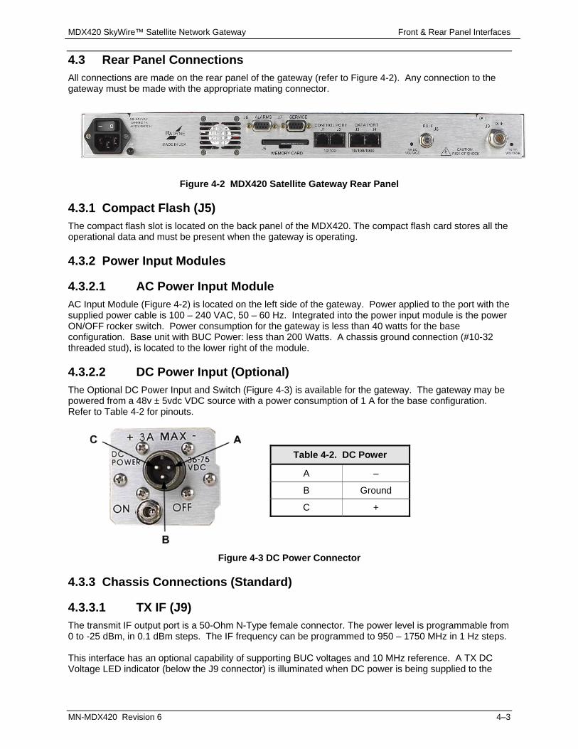
4.3 Rear Panel Connections All connections are made on the rear panel of the gateway (refer to Figure 4-2). Any connection to the gateway must be made with the appropriate mating connector.
Figure 4-2 MDX420 Satellite Gateway Rear Panel
4.3.1 Compact Flash (J5) The compact flash slot is located on the back panel of the MDX420. The compact flash card stores all the operational data and must be present when the gateway is operating.
4.3.2 Power Input Modules
4.3.2.1 AC Power Input Module AC Input Module (Figure 4-2) is located on the left side of the gateway. Power applied to the port with the supplied power cable is 100 – 240 VAC, 50 – 60 Hz. Integrated into the power input module is the power ON/OFF rocker switch. Power consumption for the gateway is less than 40 watts for the base configuration. Base unit with BUC Power: less than 200 Watts. A chassis ground connection (#10-32 threaded stud), is located to the lower right of the module.
4.3.2.2 DC Power Input (Optional) The Optional DC Power Input and Switch (Figure 4-3) is available for the gateway. The gateway may be powered from a 48v ± 5vdc VDC source with a power consumption of 1 A for the base configuration. Refer to Table 4-2 for pinouts.
Figure 4-3 DC Power Connector
4.3.3 Chassis Connections (Standard)
4.3.3.1 TX IF (J9) The transmit IF output port is a 50-Ohm N-Type female connector. The power level is programmable from 0 to -25 dBm, in 0.1 dBm steps. The IF frequency can be programmed to 950 – 1750 MHz in 1 Hz steps. This interface has an optional capability of supporting BUC voltages and 10 MHz reference. A TX DC Voltage LED indicator (below the J9 connector) is illuminated when DC power is being supplied to the
Table 4-2. DC Power
A –
B Ground
C +

MDX420 SkyWire™ Satellite Network Gateway Front & Rear Panel Interfaces
MN-MDX420 Revision 6 4–4
BUC. In addition, the gateway supports monitoring features that provide verification of system status. The gateway monitors both the current and the voltage at the output of the transmit port, thus allowing the user to monitor the status of both the indoor gateways and outdoor equipment.
4.3.3.2 RX IF (J8) The receive IF input port is a 75 Ohm F-Type female connector. The IF frequency can be programmed from 950 to 2050 MHz in 1 Hz Steps. This interface supports LNB voltages and the capability of supporting an optional 10 MHz reference. . A RX DC Voltage LED indicator (below the J8 connector) is illuminated when DC power is being supplied to the LNB. In addition, the gateway supports monitoring features that provide verification of system status. The gateway monitors both the current and the voltage at the input of the receive port, thus allowing the user to monitor the status of both the indoor gateways and outdoor equipment.
4.3.3.3 Alarm (J6) The Alarm Port is a 9-Pin Female “D” Connector. Refer to Table 4-3 for pinouts.
Table 4-3. ALARM Port 9-Pin Female “D” Connector (J6)
Pin No. Connection Direction
1 Summary Fault - NO No Direction
2 Summary Fault – C No Direction
3 Summary Fault – NC No Direction
4 Ground Ground
5 Mod Fault (open collector) Output
6 Demod 1 Fault (open collector) Output
7 Demod 2 Fault (open collector) Output
8 Demod 3 Fault (open collector) Output
9 Demod 4 Fault (open collector) Output

MDX420 SkyWire™ Satellite Network Gateway Front & Rear Panel Interfaces
MN-MDX420 Revision 6 4–5
4.3.3.4 Service Port (J7) The Service port is a 9-Pin female “D” connector. The service port allows access to the MDX420 Terminal screens. The Terminal screens allow the use of an external terminal for basic monitor and control of the MDX420. No external software is required other than a VT100 terminal emulation software (e.g. HyperTerminal or ProComm) when a computer is used as a terminal. Please Note: The Service port offers a limited set of monitor and control functions and is not intended to be a full service monitor and control port. Full monitor and control of the SkyWire gateway is supported via the SNMP Control interface. The electrical interface of the service port is RS232. The terminal control mode supports VT100 terminal emulation mode, 19.2 kbaud rate, and must be set for 8 data bit, 1 stop bit and no parity (8, N, 1). . Available Menus: Refer to section 6 for description of the Terminal screens
Demodulator Controls Demodulator Alarms Modulator Controls Modulator Alarms System Controls System Alarms TCP/IP/FTP SNMP v1, v2 & v3 Event Log Test and Diagnostic Logout
Refer to Table 4-4 for connector pinouts.
Table 4-4. Service Port (RS-232) 9-Pin Female “D” Connector (J7)
Pin No. Signal Name Signal Direction
1 No Connect
2 Receive Data RS-232 RXD-232 Input
3 Transmit Data RS-232 TXD-232 Output
4 No Connect NC
5 Ground GND
6 No Connect
7 No Connect
8 No Connect
9 No Connect
4.3.3.5 Control Port, Ethernet 10/100 (J1 & J2) The control port (J1 & J2) is used for the Monitor & Control (M&C) of the gateway. The physical interface is a standard female RJ-45, Auto-Crossover and Auto-Sensing, 10/100 Connector. Connecting to either control port is a valid connection for M&C of a single gateway.

MDX420 SkyWire™ Satellite Network Gateway Front & Rear Panel Interfaces
MN-MDX420 Revision 6 4–6
4.3.3.6 Data Port, Ethernet 10/100/1000 (J3 & J4) The Ethernet data interface provides two RJ-45, Auto-Crossover and Auto-Sensing, 10/100/1000 Ethernet data ports. J3 is Port 1 J4 is Port 2

MDX420 SkyWire™ Satellite Network Gateway Configuring the MDX420 SkyWire
MN-MDX420 Revision 6 5–1
Chapter 5. Configuring the MDX420 SkyWire
5.1 Initial Setup of the MDX420 SkyWire This section describes the initial setup and configuration of the MDX420. You must have a thorough understanding of the overall system requirements and future expansion needs before you configure the unit.
5.2 Function Accessibility All of the configuration parameters of the gateway are available through the 10/100 Ethernet control port using SNMP V1, V2, or V3 protocol The service port offers limited access to the gateway’s parameters through menu-driven terminal screens. TCP/IP setting and Passwords for the control port are established through service port terminal screens. Refer to Chapter 6 for terminal screens and Chapter 7 for the Comtech-supplied GUI Configuration Controller information. The gateway supports these M&C interfaces:
Control Port - 10/100 Ethernet - Configuration Controller GUI, SNMP v1&v2 or v3, MIB Browser ,or user-supplied NMS
Service Port - RS232 - VT100 terminal screens (limited functions)
5.3 Initial Configuration Check The MDX420 is shipped from the factory with preset factory defaults. At initial power-up, do a user check to verify the shipped gateway configuration. You can reset the modem to its original factory defaults. Log in to the modem and enter the command “DNV” on the top-level screen of the serial terminal interface. To save user configuration settings, enter the “SNV” command. To load the saved user configuration, enter the “LNV” command. Saving a user configuration creates a “USER.NV” file in the “Archive” folder on the compact flash. See section 7.4.5 to understand how this can also be done from the GUI.
IMPORTANT DO NOT EDIT the “DEFAULT.NV” file. Doing so can corrupt the default non vol settings and make the product unstable.

MDX420 SkyWire™ Satellite Network Gateway Configuring the MDX420 SkyWire
MN-MDX420 Revision 6 5–2
5.3.1 Standard Factory Configuration Settings Modulator: Demodulator
Data Rate: 1.0 Mbps FEC: 0.793 Rate Turbo Modulation: QPSK Frequency: 950 MHz Modulator Output Power: -25 dBm Modulator: Enabled BUC Power: OFF (when installed) 10 MHz Reference: OFF (when installed)
Data Rate: 1.0 Mbps FEC: 0.793 Rate Turbo Modulation: QPSK Frequency: 950 MHz LNB Power: OFF 10 MHz Reference: OFF
5.4 Initial Power-Up
CAUTION Before initial power up of the gateway, disconnect the transmit output from the operating ground station equipment. If the current Burst Modulator Configuration Settings are unknown, incorrect settings can disrupt existing communications traffic.
New gateways from the factory are normally shipped in a default configuration that includes setting the transmit carrier OFF. To power on the gateway, set the rear panel switch (near the power entry connector) to ON. At every power-up, the unit will test itself, several of its components, and front panel LEDs before operation. If a failure is detected, the Common Fault LED glows. You can do the initial field checkout of the gateway from the Comtech-supplied Gateway Configuration Controller GUI, or use an external device with the supplied SNMP MIB.
5.5 Monitor and Control Monitor and Control of the MDX420 occurs through Ethernet and terminal communications. The administrator must use the service port to set up and configure the control port. Use the control port to configure the gateway and the network. The gateway control port is configured with factory defaults.
5.5.1 Ethernet Control Port Factory Defaults: Boot Mode: NON-VOL IP Mask: 255.255.255.0 Modem IP Addr: 192.168.0.236 SNMP V2 Read Community public Read/Write Community public
5.5.2 Control Port (J1 & J2) You must set up the Control port interface parameters (TCP/IP & SNMP) through the Service port before you can use the Control port. See Appendix B for information on setting up the Control port. The Control port is dedicated to 10/100 Ethernet using SNMP protocol for Monitor and Control of the gateway. The administrator uses the Control port to control all parameters of the satellite gateway. Comtech supplies a GUI application, Configurator Controller Software, to use for setting up and monitoring the gateway.
5.5.3 Service Port (J7) The Service port is dedicated to menu-driven terminal communications. The Service port gives access to the MDX420 terminal screens. The terminal screens give limited access to monitor and control the MDX420 using an external terminal or computer. The terminal screens give access to the unit's parameters and TCP/IP settings. The Service port does not allow setup of the network configuration parameters. Refer to Chapter 6 for more about configuration using the Service port.
MDX420 SkyWire™ Satellite Network Gateway Terminal Screens
MN-MDX420 Revision 6 6–1
Chapter 6. Terminal Screens
6.1 Service Port User Interface This section contains information pertaining to the terminal screens accessible via the service port interface. Please Note: The service port offers a limited set of monitor and control functions and is not intended to be a full service monitor and control port. Full monitor and control of the SkyWire gateway is supported via the SNMP control interface.
6.2 Description of the Service Port (J7) The Service port is a 9-Pin Female “D” Connector. The service port allows access to the MDX420 Terminal Screens. The service port uses a RS232 Connection to the terminal device. Refer to section 6.1.4 for available Menus.
6.2.1 Terminal Screens The Terminal screens allow the user with an external terminal limited access for monitor and control of the gateway. No external software is required other than Terminal Emulation Software (e.g. "Hyperterminal" or “Procomm” for a computer when used as a terminal. Terminal screens allow for two modes of access, Administrative and Viewer. Administrator - requires user to login thus allowing the user full control of the unit parameters. Viewer - user can view most menus and cannot change any parameters. NOTE: The default Logon password is “password”. Administrative Passwords for the SkyWire Configuration Controller software (SkyWire Controller) can only be modified in the Terminal screens. SNMP V1, V2 and V3 are supported. When V3 is used, three contexts are supported: VIEWER, OPERATOR, and ADMINISTRATOR, Context, Authentication and Privacy are a portion of each SNMPV3 message. Password for the Terminal screen can only be modified in the SkyWire Controller System menu (See Section 7.3.5 “Service Port Admin Password”). The System menu displays the option to change the Terminal Passwords.
MDX420 SkyWire™ Satellite Network Gateway Terminal Screens
MN-MDX420 Revision 6 6–2
6.2.2 Reserved
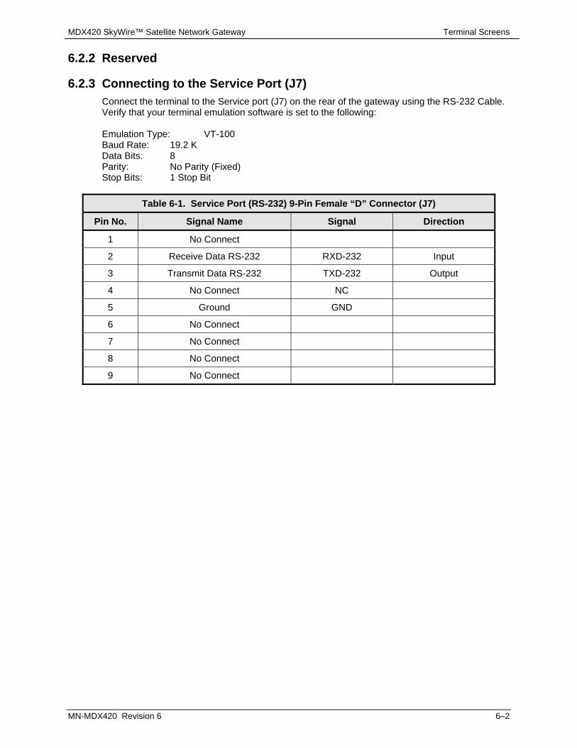
6.2.3 Connecting to the Service Port (J7) Connect the terminal to the Service port (J7) on the rear of the gateway using the RS-232 Cable. Verify that your terminal emulation software is set to the following: Emulation Type: VT-100 Baud Rate: 19.2 K Data Bits: 8 Parity: No Parity (Fixed) Stop Bits: 1 Stop Bit
Table 6-1. Service Port (RS-232) 9-Pin Female “D” Connector (J7)
Pin No. Signal Name Signal Direction
1 No Connect
2 Receive Data RS-232 RXD-232 Input
3 Transmit Data RS-232 TXD-232 Output
4 No Connect NC
5 Ground GND
6 No Connect
7 No Connect
8 No Connect
9 No Connect

MDX420 SkyWire™ Satellite Network Gateway Terminal Screens
MN-MDX420 Revision 6 6–3
6.2.4 Terminal Screens
6.2.4.1 Main Menu
Available Menus include:
Demodulator Controls (1-4) Modulator Controls System Controls Demodulator Alarms (1-4) Modulator Alarms System Alarms TCP/IP/FTP SNMP V1, V2 & V3 Event Log Test & Diagnostics LOGON

MDX420 SkyWire™ Satellite Network Gateway Terminal Screens
MN-MDX420 Revision 6 6–4
6.2.4.2 Demodulator Menu Options and Parameters (Common to all installed Burst Demodulators)
DEMODULATOR MENU 1 THROUGH 4 NETWORK SPEC {RAD MESH}
Allows the user to enter the Network specs. IF FREQUENCY (MHz)
{950 - 2050 MHz} Allows the user to enter the Burst Modulator IF Output Frequency of the gateway in 1 Hz increments.
RF FREQUENCY (MHz)
Displays the input frequency to the LNB also referred to as Satellite downlink frequency. The user must enter the LNB LO and OSC SIDE BAND before using this menu. The DOWNLINK FREQUENCY is a calculated measurement of both the LNB LO and OSC SIDE BAND. Once the menus are entered correctly, the user can control the uplink Frequency from this menu.
LO FREQUENCY (MHz)
Allows the user to enter the Local Oscillator frequency of the LNB LO in order for the uplink frequency to be displayed correctly (refer to the LNB manufacturer’s specifications).
SIDE BAND {LOW SIDEBAND, HIGH SIDEBAND} Allows the user to select the location of the LNB LO. The user must enter the location of the LNB LO in order for the DOWNLINK FREQUENCY to be displayed correctly. The LNB LO can be either higher or lower in frequency than the LNB INPUT frequency. If the LNB LO is higher in frequency then the user must enter HIGH SIDEBAND.
LNB 10MHz Ref {ENABLED, DISABLED} Allows the user to enable or disable the 10 MHz LNB reference clock.
LNB DC SUPPLY {ENABLED, DISABLED} Allows the user to enable or disable the LNB supply voltage.
CHANNEL CONTROL
{ENABLED, DISABLED} Allows the user to enable or disable the burst demodulator.
MDX420 SkyWire™ Satellite Network Gateway Terminal Screens
MN-MDX420 Revision 6 6–5
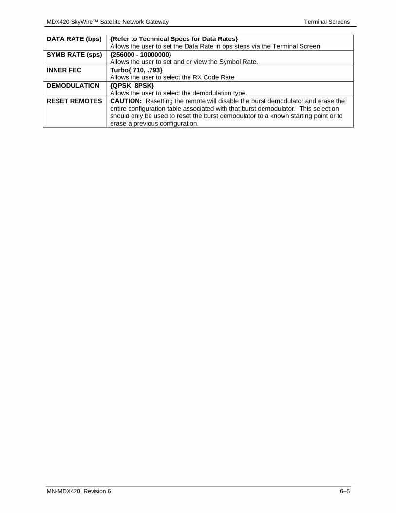
DATA RATE (bps) {Refer to Technical Specs for Data Rates} Allows the user to set the Data Rate in bps steps via the Terminal Screen
SYMB RATE (sps) {256000 - 10000000} Allows the user to set and or view the Symbol Rate.
INNER FEC Turbo{.710, .793} Allows the user to select the RX Code Rate
DEMODULATION {QPSK, 8PSK} Allows the user to select the demodulation type.
RESET REMOTES CAUTION: Resetting the remote will disable the burst demodulator and erase the entire configuration table associated with that burst demodulator. This selection should only be used to reset the burst demodulator to a known starting point or to erase a previous configuration.

MDX420 SkyWire™ Satellite Network Gateway Terminal Screens
MN-MDX420 Revision 6 6–6
6.2.4.3 Modulator Menu Options and Parameters
MODULATOR MENU
NETWORK SPEC
{RAD MESH} Allows the user to enter the desired Network specs.
IF FREQ (MHz) {950 - 1750 MHz} Allows the user to enter the Burst Modulator IF Output Frequency of the gateway in 1 Hz increments.
RF FREQ (MHz) Displays the output frequency of the BUC also referred to as Satellite uplink frequency. The user must enter the BUC LO and OSC SIDE BAND before using this menu. The UPLINK FREQUENCY is a calculated measurement of both the BUC LO and OSC SIDE BAND. Once the menus are entered correctly, the user can control the uplink Frequency from this menu.
LO FREQ (MHz) Allows the user to enter the Local Oscillator frequency of the BUC LO in order for the uplink frequency to be displayed correctly (refer to the BUC manufacturer’s specifications).
SIDE BAND {LOW SIDEBAND, HIGH SIDEBAND} Allows the user to select the location of the BUC LO. The user must enter the location of the BUC LO in order for the UPLINK FREQUENCY to be displayed correctly. The BUC LO can be either higher or lower in frequency than the BUC output frequency. If the BUC LO is higher in frequency then the user must enter HIGH SIDEBAND.
BUC 10 MHz Ref
{ENABLED, DISABLED} Allows the user to enable or disable the 10 MHz BUC reference clock.
BUC DC SUPPLY
{ENABLED, DISABLED} Allows the user to enable or disable the BUC supply voltage.
CARRIER CTL {ON, OFF} Allows the user to enable and disable the carrier.
POWER LEVEL (dBm)
{0 to -25 dBm} Allows the user to enter the Transmitter Power Level.

MDX420 SkyWire™ Satellite Network Gateway Terminal Screens
MN-MDX420 Revision 6 6–7
DATA RATE (bps)
{Refer to Technical Specs for Data Rates} Allows the user to set the Data Rate in bps steps via the Terminal Screen.
SYMBOL RATE (sps)
{256000 - 10000000} Allows the user to set and or view the Symbol Rate.
INNER FEC Turbo {.710, .793} Allows the user to select the TX Code Rate
MODULATION {QPSK, 8PSK} Allows the user to select the modulation type.
SPECTRUM {NORMAL, INVERTED} Allows the user to invert the direction of rotation for PSK Modulation. Spectral inversion may be required if the BUC LO is higher in frequency than the BUC output frequency. When BUC LO is higher than the BUC output frequency, this creates a spectral inversion and the IF Spectrum must be again inverted to compensate.
DEMOD {1-4} User can select which burst demodulator will be associated with the unit’s modulator. A value of 0 indicates the device is in RX only and is not using it’s modulator. When using the modulator a demod MUST be used to demodulate the uplink signal for timing purposes regardless if there is only one site transmitting into the share group.
REMOTE {1-8} Identifies the remote location of the network as referenced in the Network Configurator. Refer to the Network Configurator.
AUTO START {ON, OFF} Enables the gateway to automatically initiate the start of a new network. The gateway will initiate the starting process within 2 minutes of not detecting the assigned shared carrier. It will continue to attempt initialization every minute until the gateway detects the assigned shared carrier. The initialization process requires one gateway within the shared group to initialize the link. As other remote gateways are configured and set to receive the shared carrier signal, the distributed intelligence of the SkyWire network will provide access to the remotes and they will be asked to join the network.
START NETWORK
This allows the user to manually initialize the network for the first time. Once all the remotes in the SkyWire Network have been configured and the satellite parameters are set, the network can be started. The initialization process requires one gateway within the shared group to initialize the link (either in auto start mode or manually). As other remote gateways are configured and set to receive the shared carrier signal, the distributed intelligence of the SkyWire network will provide access to the remotes and they will be asked to join the network.

MDX420 SkyWire™ Satellite Network Gateway Terminal Screens
MN-MDX420 Revision 6 6–8
6.2.4.4 System Controls
SYSTEM CONTROLS
FEATURE ID 1234.1234.1234 This displays the current Feature ID. This feature code is used to define available feature within the Gateway. This code is also used for purchased feature upgrades. Feature code is different for every unit. (Refer to Appendix A).
Contact the Comtech Sales Department for hardware and software upgrades.
GATEWAY ID Fixed ID This is the unique ID that each MDX420 shipps with. This unique ID will be required by the SkyWire Configuration Controller and should be recorded by the network administrator.
MODE {FACTORY DEMO, NORMAL} Identifies the features ID mode options. Factory Demo mode is used when a 30 day demo key is requested through a sales person and will enable all software features for 30 operational days. After 30 operational days the unit will remove all un-purchased options and revert back to Normal mode.
CANCEL DEMO Allows user to cancel Factory Demo Mode. Once Demo Mode has been cancelled, the Demo ID will no longer be valid.

MDX420 SkyWire™ Satellite Network Gateway Terminal Screens
MN-MDX420 Revision 6 6–9
6.2.4.5 Demodulator Alarms (Common to all installed Burst Demodulators)
DEMODULATOR ALARM STATUS 1 THROUGH 4
DEMOD FPGA {Pass/Fail, Unmasked/Masked} Indicates a receive FPGA hardware failure.
DECODER FPGA {Pass/Fail, Unmasked/Masked} Indicates a decoder failure.
TUNER PLL {Pass/Fail, Unmasked/Masked} Indicates that the Rx L-Band Synthesizer is not locked. This alarm will flash on during certain gateway parameter changes. A solid indication points toward a configuration problem within the gateway.
SIGNAL LOCK {Pass/Fail, Unmasked/Masked} Indicates that the burst demodulator is unable to lock to a signal.
IFEC LOCK {Pass/Fail, Unmasked/Masked} FRAME LOCK {Pass/Fail, Unmasked/Masked}
Indicates that the Framing Unit is unable to find the expected framing pattern. ESNO Fault {Pass/Fail, Unmasked/Masked}
Indicates Rx signal quality fallen below input threshold. CARRIER LEVEL {Pass/Fail, Unmasked/Masked}
Indicates Rx signal level has fallen below input threshold. TESTPRN SYNC {Pass/Fail, Unmasked/Masked}
Indicates Rx pattern is synchronized to the data pattern CLEAR LATCHED Allows the user to reset the latched alarms by selecting

MDX420 SkyWire™ Satellite Network Gateway Terminal Screens
MN-MDX420 Revision 6 6–10
6.2.4.6 Modulator Alarms The Alarms menu description:
CURR - Current alarm status (PASS, FAIL) LTCH - Latched alarm status - (PASS, FAIL) displays a fault that used to exist. Unmasked - Displays all alarms and follows standard alarm protocol Masked - Hides the specified alarm and allows to unit function as if no alarm existed.
MODULATOR ALARM STATUS
MOD FPGA {Pass/Fail, Unmasked/Masked} Indicates a transmit FPGA configuration failure.
ENCODER FPGA
{Pass/Fail, Unmasked/Masked} Indicates a transmit encoder configuration failure.
IF LO SYNTH
{Pass/Fail, Unmasked/Masked} Indicates that the Tx L-Band Synthesizer is not locked. This alarm will flash on during certain gateway parameter changes. A solid indication points toward a configuration problem within the gateway.
OUTPUT LEVEL
{Pass/Fail, Unmasked/Masked} Indicates that the Output Level is out of specification.
BUC VOLTAGE
{Pass/Fail, Unmasked/Masked} Indicates that the BUC voltage is out of specification
BUC CURRENT
{Pass/Fail, Unmasked/Masked} Indicates that the BUC Current is out of specification.
CLEAR LATCHED
Allows the user to reset the latched alarms by selecting
MESH AUTH
Indicates the Gateway/Authorization ID number cannot be detected on the mesh network. This alarm is active as soon as the modulator is enabled when there is a corresponding non “0” demod associated with the modulator (see section 6.1.4.2). This alarm will clear only when the unit has successfully joined a share group and is part of the network.

MDX420 SkyWire™ Satellite Network Gateway Terminal Screens
MN-MDX420 Revision 6 6–11
6.2.4.7 System Alarms
TERR FPGA CFG {Pass/Fail, Unmasked/Masked}
Indicates an Interface Card FPGA configuration failure. GLUE FPGA {Pass/Fail, Unmasked/Masked}
Indicates Glue FPGA configuration failure. +1.2V RX SUPPLY Displays the measured voltage of the 1.2 Volt power bus located inside the
gateway. +1.8V TX SUPPLY Displays the measured voltage of the 1.8 Volt power bus located inside the
gateway. +3.3V SUPPLY Displays the measured voltage of the +3.3 Volt power bus located inside the
gateway. +5V SUPPLY Displays the measured voltage of the +5 Volt power bus located inside the
gateway. +12V SUPPLY Displays the measured voltage of the +12 Volt power bus located inside the
gateway. +24V SUPPLY Displays the measured voltage of the +24 Volt power bus located inside the
gateway. CLEAR LATCHED Allows the user to reset the latched alarms by selecting

MDX420 SkyWire™ Satellite Network Gateway Terminal Screens
MN-MDX420 Revision 6 6–12
6.2.4.8 TCP/IP/FTP Controls
TCP/IP (menu) BOOT MODE
{DEFAULT, NON-VOL, BOOTP, IP TEST} DEFAULT: During initialization (boot up), the gateway will restore the web setting to the standard IP Mask and addresses supplied by the gateway. The gateway will be taken off the network and will not be accessible. The Default settings are: IP Address Mask: 255.000.000.000 (FF.00.00.00 hex) Gateway IP Address: 010.000.000.001 (C0.A8.00.EE hex) Server IP Address: 010.001.001.001 (0A.01.01.01 hex) Router IP Address: 010.000.001.001 (0A.00.01.01 hex) BOOTP: During initialization (boot up), the gateway will get the names, masks, and IP Addresses of the gateway, router, and server. NON-VOL: Stores and uses IP Mask and addresses as provided by the user. IP TEST: Stores and uses IP Mask and addresses to fixed settings as listed below. Bootp Server Tag: 206 IP Address Mask: 255.255.255.000 (FF.FF.FF.00 hex) Gateway IP Address: 192.168.0.238 (C0.A8.00.EE) Server IP Address: 192.168.000.101 (C0.A8.00.65)
BOOTp SERVER
{128 – 257, default is 206} Only used if Bootp is selected in Boot Mode. Should be consistent with the tag expected by the users Bootp Server.
LOCAL HOST NAME
The Local Host Name for the network.

MDX420 SkyWire™ Satellite Network Gateway Terminal Screens
MN-MDX420 Revision 6 6–13
IP MASK {ddd.ddd.ddd.ddd} Decimal Mask The IP Address Mask of the local network. The mask is expressed in a hexadecimal format, and must be a valid TCP/IP Mask. This field should be set before changes are made to the Gateway or Router Address.
MODEM IP ADDR
{ddd.ddd.ddd.ddd} Decimal Mask The IP Address of the gateway. This address should be consistent for the mask defined. This address is expressed in hexadecimal format. Broadcast and loop back addresses will not be allowed. These are addresses with all subnet bits set to 0’s or 1’s.
SERVER IP ADDR
{ddd.ddd.ddd.ddd} Decimal Address The IP Address of the Boot Server and the address of the SNMP Trap Server when SNMP is active. If a server is used and there is no local router, this address must be consistent with the gateway address. If a router has been specified, the address is presumed to be reachable via the router. Broadcast and loop back addresses will not be allowed. These are addresses with all subnet bits set to 0’s or 1’s.
ROUTER IP ADDR
{ddd.ddd.ddd.ddd} Decimal Address The IP Address of the Local Network Router. If a router is present on the local network, this address must be consistent with the IP Mask and the subnet of the gateway. If no router is present, then the address should be set to a foreign address. This address is expressed in hexadecimal format. Broadcast and loop back addresses will not be allowed. These are addresses with all subnet bits set to 0’s or 1’s.
Modem Ether Addr
{hhhhhhhhhhhh} Displays the Ethernet address of the device. Set at the factory and is a unique identifier for the Ethernet physical interface.
ETHER RATE
{10/100 MBPS/Auto Negotiate} The data rate for the local Ethernet Interface. 10/100 Mbps/Auto Sensing – for 10 or 100 Base-T in either half-duplex or full duplex.
FTP User ID {XXXXXXXXXXXXXX} The FTP USER ID and Password will be shared by all sites transmitting into the same share group regardless of what is entered here. This setting is only used by the first site that starts the share group. Once in a share group any changes to the User ID or Password will be communicated to all sites in that share group automatically. The default User ID is: user
FTP Password
{XXXXXXXXXXXXXX} The FTP USER ID and Password will be shared by all sites transmitting into the same share group regardless of what is entered here. This setting is only used by the first site that starts the share group. Once in a share group any changes to the User ID or Password will be communicated to all sites in that share group automatically. The default Password is: password

MDX420 SkyWire™ Satellite Network Gateway Terminal Screens
MN-MDX420 Revision 6 6–14
6.2.4.9 SNMP V1 & V2 Controls
SNMP VERSION {V1 & V2, V3}
This selection controls the SNMP Version that will be used in messaging between the equipment and its host. When V1 & V2 is used, RD COMMUNITY and RDWR COMMUNITY are used to determine the authorization of an incoming message.
TRAP VERSION {V1, V2} This controls the type of message format used when a message trap is generated by the equipment and bound for a SNMP Host. Messages will only be sent if the gateway has been authorized to do so.
TRAP AUTHORIZATION
{TRAPS OFF, TRAPS ON} This controls the type of message format used when a message trap is generated by the equipment and bound for a SNMP host. Messages will only be sent if the gateway has been authorized to do so.
V1&2 RD COMMUNITY
{16 characters of name} This menu is only displayed when SNMP VERSION is set to V1 & V2. This is the community that a host must be acting within when an OID variable is requested by a V1/V2 SNMP message. The defaulted setting is “Public”.
V1&2 RDWR COMMUNITY
{16 characters of name} This menu is only displayed when SNMP VERSION is set to V1 & V2. This is the community that a host must be acting within when an OID variable is being changed by a V1/V2 SNMP message. The defaulted setting is “public”.
PRIMARY TRAP HOST
{xxx.xxx.xxx.xxx} This specifies the IP address of the "public" SNMP host. Trap messages are sent to this address when a trap is generated by the equipment.

MDX420 SkyWire™ Satellite Network Gateway Terminal Screens
MN-MDX420 Revision 6 6–15
6.2.4.10 SNMP V3 Controls
SNMP VERSION {V1 & V2, V3}
This selection controls the SNMP Version that will be used in messaging between the equipment and its host. When V3 is used, three contexts are supported: VIEWER, OPER, and ADMIN. Context, Authentication and Privacy are a portion of each SNMPV3 message. The VIEWER context will only allow the user with appropriate authentication to see the local gateway settings. This is the most restricted access possible. The OPER context allows a user with appropriate authentication to access and control the local gateway parameters. The ADMIN context allows a user with appropriate authentication to access and control all network parameters. These OIDs are used to control the devices, satellite link and operation.
TRAP VERSION {V1, V2} This controls the type of message format used when a message trap is generated by the equipment and bound for a SNMP Host. Messages will only be sent if the gateway has been authorized to do so.
TRAP AUTHORIZATION
{TRAPS OFF, TRAPS ON} This controls the type of message format used when a message trap is generated by the equipment and bound for a SNMP host. Messages will only be sent if the gateway has been authorized to do so.
PRIMARY TRAP HOST
{xxx.xxx.xxx.xxx} This specifies the IP address of the "public" SNMP host. Trap messages are sent to this address when a trap is generated by the equipment. NOTE: The following selections are common to all users. These settings will be used as access parameters for the Configurator Controller. The gateway allows for 4 distinct users that are identified in this menu.
USER # Sets user display name. User default names are administrator, operator and viewer. This is also referred to as the Security User Name in the User Profile Configuration.

MDX420 SkyWire™ Satellite Network Gateway Terminal Screens
MN-MDX420 Revision 6 6–16
GROUP {ADMIN, OPER, VIEWER, NO GROUP} Sets the group access level for the user. This is also referred to as the Context Name in the User Profile Configuration.
AUTHP Sets the Authentication Password for the user. Password must match the Authentication Password in the User Profile Configuration
PRIVP Sets the Privacy Password for the user. Password must match the Privacy Password in the User Profile Configuration
AUTHM {MD5, SHA, NONE} Sets the Authentication mode for the user. Mode must match the Authentication Protocol in the User Profile Configuration
PRIVM {DES, NONE} Sets the Privacy mode for the user. Mode must match the Privacy Protocol in the User Profile Configuration
USER RESET Resets the User defaults.

MDX420 SkyWire™ Satellite Network Gateway Terminal Screens
MN-MDX420 Revision 6 6–17
6.2.4.11 Event Log

MDX420 SkyWire™ Satellite Network Gateway Terminal Screens
MN-MDX420 Revision 6 6–18
6.2.4.12 Test Diagnostics
Carrier TYPE {NORMAL, CW, DUAL, OFFSET, POS FIR, NEG FIR, CNT MOD}
Allows the user to set the type of carrier. NORMAL: Causes the Burst Modulator to output normal modulation. CW: Causes the Burst Modulator to output a pure carrier. DUAL: Causes a double sideband output. OFFSET: Causes a single sideband output. POS FIR: For manufacturer’s use only. NEG FIR: For manufacturers use only. CNT MOD: Transmits a continuously modulated carrier. This mode is used to verify the proper bandwidth and noise level margin of the carrier within the satellite transponder. This is may also be used for antenna alignment. The test mode does not allow any data to be transmitted. CNT BST: Continuous Burst mode tells the modulator to send a burst at every time slot regardless of burst slot assignment. This type of operation is very useful when installing the first site of a share group or for debugging a network issue. CNT BST will look like an SCPC carrier on a spectrum analyzer (virtually always on) and it will satisfy any demodulator who is properly configured to lock to the signal. CNT BST can be used to verify frequency, Spectral Inversion and Symbol rates are properly set and to verify the uplink and downlink chain are in good working order.
LOOPBACK {NONE} This is not available in the MDX420 MOD TEST PATTERN {NONE} This is not available in the MDX420 DEMOD1-4 {NONE} This is not available in the MDX420

MDX420 SkyWire™ Satellite Network Gateway SkyWire Controller (GUI)
MN-MDX420 Revision 6 7–1
Chapter 7. SkyWire Controller GUI
7.1 SkyWire Controller Graphical User Interface (GUI) At the time of this publication, the GUI version is 1.8.5(H). The SkyWire Controller is also referred to in this manual as SkyWire GUI or GUI. Using the Comtech supplied SkyWire Controller software requires the user to install the SkyWire Controller software onto a PC. The GUI gives the user access to the menus for setting up the gateway and network parameters. The GUI is included with the purchase of the MDX420. PC System Requirements are: Java 7 or greater Windows 7 or 8 13.7 MB free space (HDD) 128 MB free memory (RAM)

MDX420 SkyWire™ Satellite Network Gateway SkyWire Controller (GUI)
MN-MDX420 Revision 6 7–2
7.2 Installing the SkyWire Controller GUI The SkyWire Controller installation CD is shipped with the SkyWire Gateway. Alternatively the latest SkyWire Controller software can also be found on Comtech’s customer support FTP site for download. Please contact your customer service or sales representative to get access to the FTP site. The following steps describe the installation procedure for installing the SkyWire Controller on your computer. Step 1: Place the SkyWire Controller CD-ROM in the CD-ROM Drive and double-click on the SkyWireControllerInstaller jar file. Read the Comtech license agreement carefully. Click the “I Agree” to proceed with the installation.
Step 2: Select the installation options and click “Next”.

MDX420 SkyWire™ Satellite Network Gateway SkyWire Controller (GUI)
MN-MDX420 Revision 6 7–3
Step 3: The default installation subdirectory window will appear. To use the default installation subdirectory click “Install” or click “Browse” to modify the directory for installation. Press “Install” to begin the installation.
Step 4: stand by until the installation shows “Completed”. Click “Close” to exit.

MDX420 SkyWire™ Satellite Network Gateway SkyWire Controller (GUI)
MN-MDX420 Revision 6 7–4
7.3 Connect and Login In order to activate the SkyWire Controller, the MDX420 must be turned ON and connected to the computer via the 10/100 Ethernet Control port.
Set up the Internet Protocol (TCP/IP) Properties of the computer LAN port to be on the same subnet as the Control port on the MDX420. In Windows, this is done through the Network Connections category. The factory default subnet is 192.168.0.x, where x is an address between 1 and 255 except for 236. If the IP address of the MDX420 has been changed from the factory default address, the subnet may be different. Consult your Network Administrator for the proper subnet setting for the computer.
Connect an Ethernet RJ45 cable between the computer and Control Port J1 or J2 of the MDX420. The gateway’s IP address is automatically detected by the SkyWire Controller.
On the Login screen (Figure 7.3) click the button to the right of the Destination name to configure the SkyWire Controller interface parameters.
Figure 7.3 Login Screen for SNMPv2
7.3.1 Destination Configuration Screen The Destination Configuration screen is displayed in Figure 7.3.1. This screen allows the user to provide a Destination Name for the gateway, enter the gateway IP Address, set the SNMP protocol version, and select the desired polling interval.
NOTE: The IP Address and SNMP Version parameters in the Destination Configuration screen must match the parameters set by the Service port (refer to section 6.1.4.8, 6.1.4.9, and 6.1.4.10)
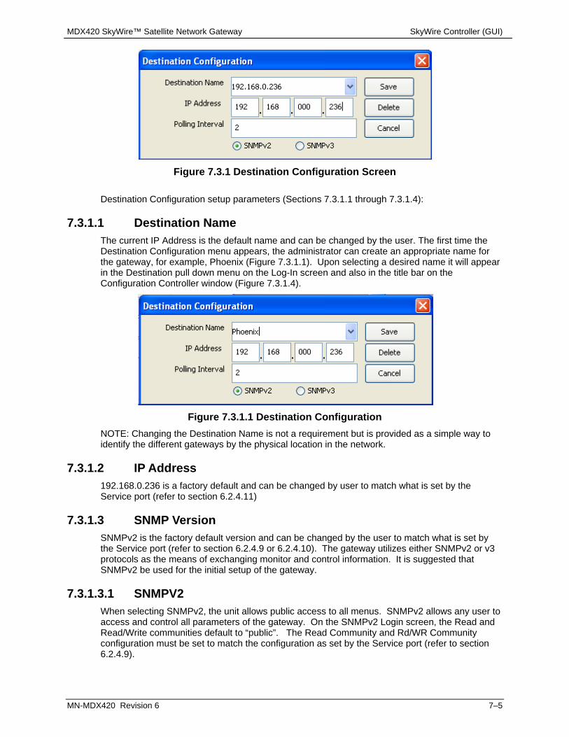
MDX420 SkyWire™ Satellite Network Gateway SkyWire Controller (GUI)
MN-MDX420 Revision 6 7–5
Figure 7.3.1 Destination Configuration Screen
Destination Configuration setup parameters (Sections 7.3.1.1 through 7.3.1.4):
7.3.1.1 Destination Name The current IP Address is the default name and can be changed by the user. The first time the Destination Configuration menu appears, the administrator can create an appropriate name for the gateway, for example, Phoenix (Figure 7.3.1.1). Upon selecting a desired name it will appear in the Destination pull down menu on the Log-In screen and also in the title bar on the Configuration Controller window (Figure 7.3.1.4).
Figure 7.3.1.1 Destination Configuration
NOTE: Changing the Destination Name is not a requirement but is provided as a simple way to identify the different gateways by the physical location in the network.
7.3.1.2 IP Address 192.168.0.236 is a factory default and can be changed by user to match what is set by the Service port (refer to section 6.2.4.11)
7.3.1.3 SNMP Version SNMPv2 is the factory default version and can be changed by the user to match what is set by the Service port (refer to section 6.2.4.9 or 6.2.4.10). The gateway utilizes either SNMPv2 or v3 protocols as the means of exchanging monitor and control information. It is suggested that SNMPv2 be used for the initial setup of the gateway.
7.3.1.3.1 SNMPV2 When selecting SNMPv2, the unit allows public access to all menus. SNMPv2 allows any user to access and control all parameters of the gateway. On the SNMPv2 Login screen, the Read and Read/Write communities default to “public”. The Read Community and Rd/WR Community configuration must be set to match the configuration as set by the Service port (refer to section 6.2.4.9).
MDX420 SkyWire™ Satellite Network Gateway SkyWire Controller (GUI)
MN-MDX420 Revision 6 7–6
7.3.1.3.2 SNMPV3 When selecting SNMPv3, the gateway enables administrative controls and allows limited access to all other users. In this mode, the administrator retains access to all parameters but can limit access to certain users by assigning them as Viewers, Operators, or Administrators and must be set to match the configuration as set by the Service port (refer to section 6.2.4.10). Configuring SNMP Version 3 will be described later in this chapter.
7.3.1.4 Polling Interval The SkyWire Controller will poll the gateway based on the setting of the Polling Internal (in seconds). The default setting is 2 seconds and an be changed by the user to the desired polling interval Click on the Save button to store the destination profile for easy future access. Once the user is authenticated, a quick summary (Figure 7.3.1.4) of the burst demodulators and network status, event logs, and summary faults is displayed.

MDX420 SkyWire™ Satellite Network Gateway SkyWire Controller (GUI)
MN-MDX420 Revision 6 7–7
7.4 SkyWire Controller Configure Tab After successfully logging into the configuration controller, the user must first configure the MDX420 satellite link parameters to the desired setting. Satellite Link menus include but are not limited to:
Figure 7.4 SkyWire Configuration Controller
RF Frequency IF Frequency Modulation Inner FEC (Forward Error Correction) Standard or Enhanced Performance Data Rate Symbol Rate Block Up Converter (BUC) Low Noise Block (LNB) converter
NOTE: The MDX420 allows the user to determine if the frequency control for the burst modulator and burst demodulator are either IF or RF and if the information rate control is to be entered as symbol rate or data rate. Refer to Section 7.4 for control options settings.
Using the SkyWire top-level menu system, select the Configure / Satellite Link / Modulator menu (Figure 7.4-1).

MDX420 SkyWire™ Satellite Network Gateway SkyWire Controller (GUI)
MN-MDX420 Revision 6 7–8
Figure 7.4-1. Satellite Link Menu Selection
The satellite link configuration window (Figure 7.4.1.1) provides access to all gateway satellite configuration parameters through the use of tabs. Select a tab for the section of the gateway where satellite link parameters are to be changed. that you want to configure.
7.4.1 Configure Satellite Link
7.4.1.1 Modulator Configuration To setup the burst modulator, select the Modulator tab in the Satellite Link Configuration screen. Press the Edit button to make changes and once satisfied with the new settings, click on the Apply button to have them take effect.
Figure 7.4.1.1 Modulator Tab Edit Mode
TX Enable: Tx Enable should be selected when the MDX-420 is transmitting into the network. Regardless of any other setting, if TX Enable is not selected the MDX-420 will not TX into the network. Un-select this box if the MDX-420 is used in a receive only capacity.
Auto Start: The Auto Start function allows a share group to automatically recover from a complete outage. It is primarily intended for use in unattended networks. The Auto Start function can be enabled by placing a Check in the Auto Start check box on the Modulator tab in the Satellite Link Configuration screen (Figure 7.4.1.1). Beginning two minutes after power-up, the MDX-420 operation with regard to Auto Start is as follows:

MDX420 SkyWire™ Satellite Network Gateway SkyWire Controller (GUI)
MN-MDX420 Revision 6 7–9
If the Auto Start function is enabled, the MDX-420 determines if it can receive the designated share group’s channel. If there is no share group carrier to receive, the MDX-420 attempts to start the network. Wait one minute Go to step 1.
NOTE: It is NOT recommended that Auto Start be enabled on more than one MDX-420 within a share group.
The decision as to which, if any, MDX-420 has the Auto Start function enabled should include the following two considerations:
Likelihood of a signal outage at that site – If possible, select an MDX-420 at a site that has the least chance of an outage. Access to the MDX-420 – If possible, select an MDX-420 to which the network administrator has either direct or non-over-the-air access.
Network Spec: Network spec is set to RADYNE MESH and is not changeable at this time.
Performance: The Performance selection can be set to Standard or Enhanced. This setting must be the same for all units that are transmitting into the same share group. The performance setting is a trade-off of Eb/No required to close the link and bandwidth efficiency. See the below table to understand how this setting will affect network performance:
Selected Demod: The Selected Demod is the demod that is associated with the modulated signal. Every MDX-420 that is transmitting into a share group must be locally demodulated in order to meet timing and BW sharing algorithm criteria. The Selected Demod is the physical demod slot that is associated with the modulator’s share group. By default this is demod slot 1 as this demod is always populated from the factory. The demod can be set to any populated demod slot if more than one demod is purchased and installed in the MDX-420. A Selected Demod setting of “0” means that the MDX-420 is in a listen only mode and can not transmit into any share group.
Selected Remote: The Selected Remote is automatically assigned by the network and can not be changed. This number correlates to the physical location on the GUI interface. A number of 2 for example would indicate that this site is in position 2 of the bar graph of a multiple site share group. Note: each share group will re-start the count so the number of the remote will always be between 1-8 for a particular share group. Alternatively, when viewing the GUI interface, the “yellow” bar is another way to know what MDX-420 device you have the SNMP session with.
Gateway ID: This is the unique ID that each MDX420 shipps with. This unique ID will be required by the SkyWire Configuration Controller and should be recorded by the network administrator. NOTE: The Gateway ID will be needed to configure the network (see section 7.6).
All other configurable items in the modulator configuration screen should be treated as if configuring any other satellite modem.
7.4.1.2 Demodulator Configuration There are up to four burst demodulators that may be installed in the SkyWire Gateway. To configure any of the installed burst demodulators, select the corresponding demod tab. Press the
Modulation and Coding Threshold Eb/No Typical Eb/No Efficiency1) Enhanced - QPSK.710 2.9 3.5 90%2) Enhanced - QPSK.793 3.3 3.8 90%3) Standard - QPSK.793 3.4 4.4 93%4) Enhanced - 8PSK.793 6.5 7.6 88%5) Standard - 8PSK.793 7.8 9.0 91%

MDX420 SkyWire™ Satellite Network Gateway SkyWire Controller (GUI)
MN-MDX420 Revision 6 7–10
Edit button (Figure 7.4.1.2) to make changes and once satisfied with the new settings, click on the Apply button to have them take effect.
Repeat the above process for all installed burst demodulators.
Figure 7.4.1.2 Demodulator 1 Tab Edit Mode
RX Enable: Rx Enable should be checked if you wish to demodulate and receive traffic from a share group on this demodulator. Unchecking this box will disable the demodulator regardless of any other settings.
CRC Control: The gateway allows users to enable or disable CRC Control. When CRC Control is checked, the gateway automatically performs Ethernet packet error checking on the receive Satellite Link. When an Ethernet packet with a bad CRC is encountered, the packet is discarded by the gateway.When CRC Control is unchecked, the gateway will remove the invalid CRC and append a valid CRC to the Ethernet datagram and pass the packet to the LAN network. Enabling CRC Control may be suitable for users that need all packets to pass based on their application. Regardless of the configuration of the CRC Control function, enabled or disabled, the gateway maintains and reports satellite link statistics on total packets, erred packets, and packet error rate (PER). Note: CRC Control is only used on the RX satellite link. If an invalid CRC is seen by the 10/100/1000 Interface the packet will be disgarded and will not be transmitted to the satellite regardless of the CRC Control check box selection.
Performance: See section 7.4.1.1
All other configurable items in the demodulator configuration screen should be treated as if configuring any other satellite modem.
7.4.1.3 BUC and LNB Configuration To setup the BUC (Figure 7.4.1.3-1) and/or LNB (Figure 7.4.1.3-2), select the corresponding tab on the satellite link configuration window. Enter the LO frequency and LO Mix (Hi side or Low side). Click on the Enable button to activate the DC Supply and or 10MHz Frequency Reference to the BUC or LNB. They are individually controlled with a checked box meaning that they are enabled, unchecked box meaning that they are disabled.
Once satisfied with the new settings, click on the Apply button to have them take effect.
Warning: Care must be taken to insure that the DC Supply Enable is Disabled when connecting the SkyWire Gateway to external equipment that cannot accept a DC voltage

MDX420 SkyWire™ Satellite Network Gateway SkyWire Controller (GUI)
MN-MDX420 Revision 6 7–11
input, such as a Spectrum Analyzer. Failure to do so may result in damage to the external equipment.
Figure 7.4.1.3-1 BUC Tab Edit Mode
Figure 7.4.1.3-2 LNB Tab Edit Mode
7.4.1.4 AUPC Configuration AUPC or “Automatic Uplink Control” operation is an OPTIONAL setting and does not need to be configured to enable SkyWire to function. AUPC operation is designed to compensate for UPLINK fade conditions. By default AUPC is not enabled. If a user wants to mitigate the effects of uplink fade the SkyWire modem can be configured to do so. Note: Improper use of AUPC can take a network down and may damage ground equipment or use excessive power on the satellite. Read below carefully.

MDX420 SkyWire™ Satellite Network Gateway SkyWire Controller (GUI)
MN-MDX420 Revision 6 7–12
Figure 7.4.1.4 AUPC Configuration
Theory of operation: Fade conditions can happen for numerous reasons such as uplink rain fade, downlink rain fade, antenna mispointing, LNB failure, BUC failure, cable run issues, temperature etc. The purpose of SkyWire’s AUPC is to try and mitigate the effects of UPLINK fade ONLY. The reason we do not want to mitigate the effects of downlink fade is due to the fact that SkyWIre is designed to work in a MESH environment so compensating for one site’s downlink fade will overdrive the uplink power and the system will be using more of the satellite power resources than the satellite operator would typically allow. Further to this point increasing the uplink power to compensate for one site’s downlink rain fade would negatively impact all sites that did NOT have downlink fade. The purpose of SkyWire’s AUPC is to attempt to illuminate the satellite with a constant or near constant power and to overcome uplink rain fade. The use of AUPC is a site by site selection, some units in the share may use this while others in the same share group may not. AUPC only effects the TX power of the device being configured to use AUPC and the demodulator RX level is only reading the level of it’s own burst not the RX level of other sites or an average of all sites in the share group. Operation: Once the network is up and running in a stable environment and all carrier levels and Eb/No levels are within the operational range desired (see section 7.6.1 Demodulator Status Screen) AND the site in which AUPC is to be turned on is in CLEAR SKY CONDITIONS the user should follow these instructions in this exact order:
1) Click on the “Set Ideal Conditions” button. When this button is clicked, the “Ideal TX Power Level (dBm)” and “Ideal RX Power Level (dBm)” fields will populate with the present values of the modulator’s TX power setting and the demodulators Carrier Level reading. NOTE: If the actual values of the demodulator and modulator are NOT set when doing this or if the values stay at their default (0.0 dBm TX and -45 dBm RX) this means that the present conditions of the demod are NOT within SkyWire’s specification and AUPC SHOULD NOT BE USED. You will also see an event in the event log stating “INVALID AupcIdealRXCarrierLeveldBm”. If you get this message in the Event Log DO NOT USE AUPC.
2) Set the TX % Fade figure to a number between 50 and 90 (more on this below).

MDX420 SkyWire™ Satellite Network Gateway SkyWire Controller (GUI)
MN-MDX420 Revision 6 7–13
3) Set a Max TX Power Level (dBm) (any figure from 0 to -25). Note: Do NOT set an
excessively large Max TX Power level unless there is a reason to believe all of the excess power could actually be used strictly for uplink rain fade.
4) Enable AUPC by checking the box
5) Click Apply TX % Fade: The demodulator carrier level used in AUPC is a measurement of it’s own burst as seen by the demod from the satellite. Unfortunately if there is a fade condition at the site, what the demod is seeing is both the uplink fade and the downlink fade. We want to compensate for the uplink fade only for reasons mentioned above, so we need to determine what percentage of the fade is due to the uplink and what percentage of the fade is due to the downlink. Generally speaking uplink frequencies are higher than downlink frequencies and because of this there is generally more fade on the uplink (this is a good thing because this is what we can compensate for). The TX fade percentage can be calculated using the following math:
TX% Fade = TX Fade /(TX Fade + RX Fade) Example: Ku Band link with with 4.4dB of total fade. Due to the frequencies used, 2.4 dB is due to the uplink and 2.0dB is due to the downlink. This site has a TX% Fade of 55%. Below is a table of common TX Fade % Figures using the center of each Band as the metric for fade %
Downlink (GHz) Uplink (GHz) TX Fade %
Band flow fhigh fmid flow fhigh fmid TX Fade / (TX + RX Fade)
C-band 3.4 4.2 3.8 5.85 6.65 6.25 72%
X-band 7.25 7.75 7.5 7.9 8.4 8.15 54%
Ku-band 11.7 12.2 11.95 14 14.5 14.25 58%
Ka-band 20.2 21.2 20.7 30 31 30.5 63% Max TX Power Level (dBm): Take care in setting the Max TX Power level. Although tempting to simply allow the modem to TX up to it’s maximum capability in doing so you are taking far more risk than is necessary and can seriously damage equipment or take down the network. As mentioned above, fade comes in many forms and if for example cables on the RX chain were slowly deteriorating or the antenna was slightly pointed incorrectly, the demod will see all of this as fade and try to compensate by changing the uplink power. In a clear sky condition with bad RX cables a demod seeing a fade will increase the power to try to compensate for this fade up to the maximum power set in this parameter. For this reason it is best to take some time and determine how much total rain and thus how much total UPLINK fade the site could actually see and to calculate the maximum amount of uplink power needed to illuminate the satellite in worst fade conditions. In doing so you will reduce the impact of other fade conditions.

MDX420 SkyWire™ Satellite Network Gateway SkyWire Controller (GUI)
MN-MDX420 Revision 6 7–14
7.4.2 Configure Terrestrial Interface The Terrestrial Interface window allows access to setup Control port and Data port parameters. Ethernet controls like flow control and Quality of Service are supported. QoS offers the ability to provide different priority to different applications, users, or data flows to guarantee a certain level of performance to a data flow. Refer to Figure 7.4.2-1.
Figure 7.4.2-1 Terrestrial Interface
In Band Control: When In-Band Control is checked, the MDX-420 will allow itself to be monitored and controlled locally through Control Ports J1 & J2 or by a remote gateway over the satellite link without an external connection between the control port and the data port. When unchecked, a SNMP session can only occur locally through Control Ports J1 or J2.
FLOW CONTROL: When checked it auto-negotiates rate of data transmission with the device connected to the MDX420. When unchecked no back pressure is applied to connecting routers or switches for flow control.
DAISY CHAIN MODE: Daisy Chain Mode can be used whenever a single site is demodulating more than 4 share groups as is commonly seen in Hub and Spoke applications or in larger MESH networks with 5 or more share groups. This mode is used where one (1) MDX-420 is transmitting into a share group and demodulating 1-4 share groups and there are additional MDX-420 units that are only used to demodulate additional share groups (not transmitting). Looking at Figure 7.4.2-2, the proper way to eliminate layer 2 issues such as spanning tree or endless loop when multiple MDX420 units are used is to connect the devices in the following manner. When Daisy Chain Mode is selected on a unit, traffic entering Port J4 will be forwarded to Port J3 and MAC learning and aging will be disabled on Port J4. By doing this none of the destination MAC address that come in on Port 4 will be associated to either the LAN or WAN side of the link. The MDX-420 that is being used to transmit traffic must have “Daisy Chain Mode” checked (we will call this MDX-T). The MDX-420 that is being used as a demod only (we will call this MDX-R1) must connect MDX-R1 Port J3 to MDX-T Port J4. It is a good idea to also check “Daisy Chain Mode” on MDX-R1 in case future share groups are added. It would then be possible to connect future MDX-420s being used in a demod only configuration (MDX-R2) by again connecting MDX-R2 Port J3 to MDX-R1 Port J4.
QUALITY of SERVICE (QoS): Two types supported NORMAL and PORT BASED.

MDX420 SkyWire™ Satellite Network Gateway SkyWire Controller (GUI)
MN-MDX420 Revision 6 7–15
NORMAL - Uses the following formats (IEEE 803.3ac Tag containing IEEE 802.1p priority information provided by an external device, Type of Service field (RFC 791) or Differentiated Services field (RFC 2474) contained in an IPv4 header and Traffic Class field (RFC 2460) contained in an IPv6 header. PORT BASED - In this mode, (J3) has the highest priority and (J4) has the lowest priority. The Port Based overrides any standard priority QoS QUEUE (FAIR WEIGHTED, STRICT PRIORITY) FAIR WEIGHTED: - Selects the queue weighting of 8,4,2,1 that insures even the lowest priority traffic gets some bandwidth (packets are processed in a weighted round robin manner). STRICT PRIORITY: - insures that the higher priority traffic will always be transmitted before any lower priority traffic. With this setting, the lower priority traffic can starve. First In First Out (FIFO): - In certain circumstances it may be desirable to have the Ethernet Interface to operate in a FIFO like mode with no reordering of packets. This can be done by using a single port and setting the Ethernet QoS type to Port Base and the Ethernet QoS Queue to strict priority. This will allow packets to be transmitted in the exact order in which they are received.
Default settings for the terrestrial interface are: M&C Control Port: In-Band Control: Disabled Ethernet Data Port: Flow Control: Enabled Daisy Chain: Disabled Quality of Service: Type: Normal Queuing: Fair Weighted
Figure 7.4.2-2 Daisy Chain Set up for Data Ports

MDX420 SkyWire™ Satellite Network Gateway SkyWire Controller (GUI)
MN-MDX420 Revision 6 7–16
7.4.3 Configure Network Configuration Once the SkyWire gateway satellite parameters have been configured the next step is to configure the network settings. A SkyWire gateway can be configured with up to 4 burst demodulators. From the Configure menu, select Network Configuration and click on the demod associated with the modulator (see section 7.4.1.1 “Selected Demod”). If only one burst demodulator is installed, the tabs for Demod 2, Demod 3, and Demod 4 will be grayed out. The Network configuration screen is divided into two sections. The upper section is the Channel section that shows the basic configuration of the selected burst demodulator. The lower section is the Remotes configuration section. The Remotes configuration section provides the mechanism to assign the parameters for each gateway within the network share group. Configuring a SkyWire network requires a thorough understanding of the overall network requirements prior to creating, adding, or deleting gateways in the network.
Channel Configuration: With few exceptions, the “Channel” section of the Network Configuration screen is a brief representation of what was configured and can be seen in the demod configuration (see section 7.3.1.2). Other items only available on this screen include the following:
Start Network: Clicking on this box will manually tell the MDX-420 to start a new share group if the unit is not already participating in an existing share group. The Start Network control button allows the user to initialize the network for the first time. Once one or more of the remotes in the SkyWire Network have been configured and the satellite parameters are set, the network can be started. The initialization process requires one gateway within the shared group to initialize the link. As other remote gateways are configured and set to receive the shared carrier signal, the distributed intelligence of the SkyWire network will provide access to the remotes and they will be asked to join the network.
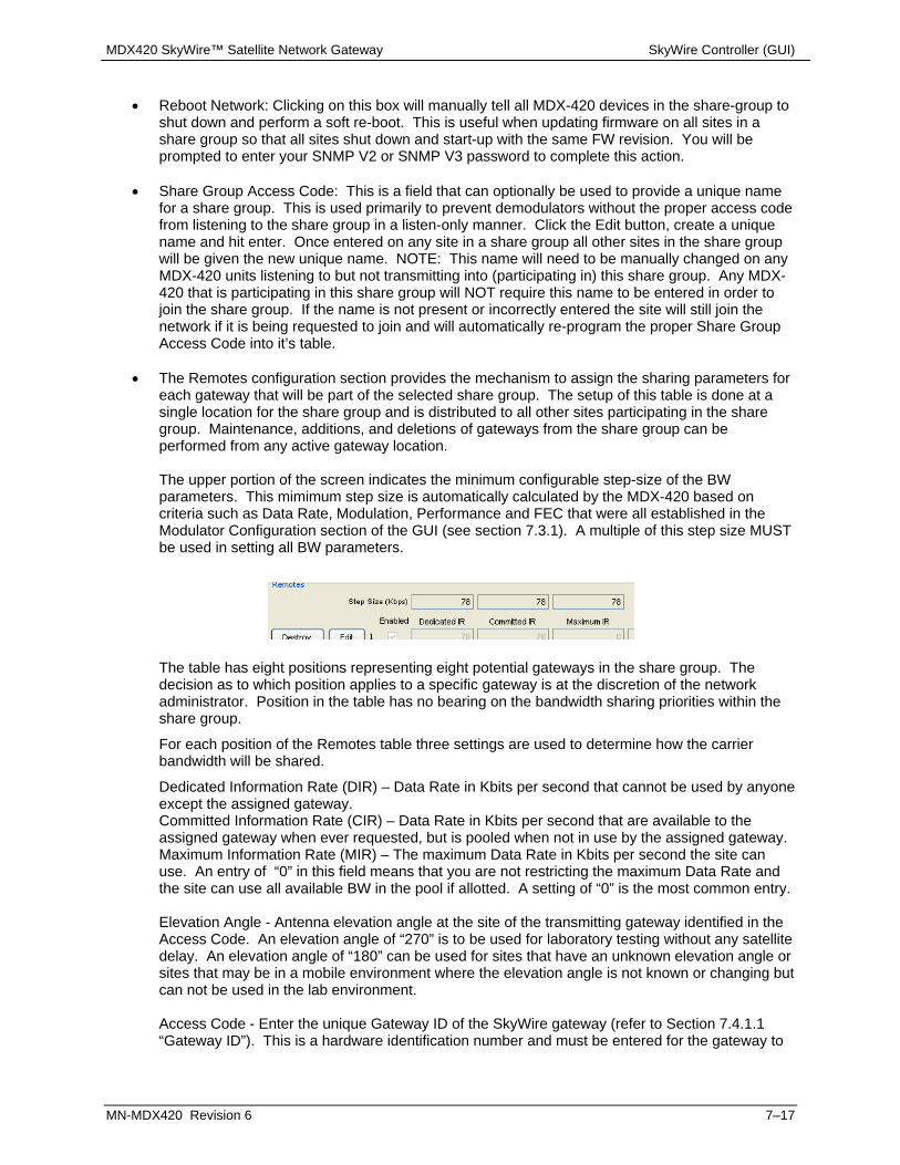
MDX420 SkyWire™ Satellite Network Gateway SkyWire Controller (GUI)
MN-MDX420 Revision 6 7–17
Reboot Network: Clicking on this box will manually tell all MDX-420 devices in the share-group to
shut down and perform a soft re-boot. This is useful when updating firmware on all sites in a share group so that all sites shut down and start-up with the same FW revision. You will be prompted to enter your SNMP V2 or SNMP V3 password to complete this action.
Share Group Access Code: This is a field that can optionally be used to provide a unique name for a share group. This is used primarily to prevent demodulators without the proper access code from listening to the share group in a listen-only manner. Click the Edit button, create a unique name and hit enter. Once entered on any site in a share group all other sites in the share group will be given the new unique name. NOTE: This name will need to be manually changed on any MDX-420 units listening to but not transmitting into (participating in) this share group. Any MDX-420 that is participating in this share group will NOT require this name to be entered in order to join the share group. If the name is not present or incorrectly entered the site will still join the network if it is being requested to join and will automatically re-program the proper Share Group Access Code into it’s table.
The Remotes configuration section provides the mechanism to assign the sharing parameters for each gateway that will be part of the selected share group. The setup of this table is done at a single location for the share group and is distributed to all other sites participating in the share group. Maintenance, additions, and deletions of gateways from the share group can be performed from any active gateway location. The upper portion of the screen indicates the minimum configurable step-size of the BW parameters. This mimimum step size is automatically calculated by the MDX-420 based on criteria such as Data Rate, Modulation, Performance and FEC that were all established in the Modulator Configuration section of the GUI (see section 7.3.1). A multiple of this step size MUST be used in setting all BW parameters.
The table has eight positions representing eight potential gateways in the share group. The decision as to which position applies to a specific gateway is at the discretion of the network administrator. Position in the table has no bearing on the bandwidth sharing priorities within the share group.
For each position of the Remotes table three settings are used to determine how the carrier bandwidth will be shared.
Dedicated Information Rate (DIR) – Data Rate in Kbits per second that cannot be used by anyone except the assigned gateway. Committed Information Rate (CIR) – Data Rate in Kbits per second that are available to the assigned gateway when ever requested, but is pooled when not in use by the assigned gateway. Maximum Information Rate (MIR) – The maximum Data Rate in Kbits per second the site can use. An entry of “0” in this field means that you are not restricting the maximum Data Rate and the site can use all available BW in the pool if allotted. A setting of “0” is the most common entry. Elevation Angle - Antenna elevation angle at the site of the transmitting gateway identified in the Access Code. An elevation angle of “270” is to be used for laboratory testing without any satellite delay. An elevation angle of “180” can be used for sites that have an unknown elevation angle or sites that may be in a mobile environment where the elevation angle is not known or changing but can not be used in the lab environment. Access Code - Enter the unique Gateway ID of the SkyWire gateway (refer to Section 7.4.1.1 “Gateway ID”). This is a hardware identification number and must be entered for the gateway to

MDX420 SkyWire™ Satellite Network Gateway SkyWire Controller (GUI)
MN-MDX420 Revision 6 7–18
properly join the share group. NOTE: If entered incorrectly the remote site will not join the network. Circuit Name – Text name to help identify the circuit. The circuit name is not a required field but if entered, the circuit name will appear as a tooltip when the mouse hovers over a remote’s graphics bar on the Demodulator Summary Status screen.
Assigning a SkyWire gateway to the network as Remote 1 is a simple three step process (Figures 7.4.3-1 through 7.4.3-3).
1 Click on the Create control button on the left of the first position in the Remotes table. 2 Click on the Edit control button to begin entering the network parameters:
set the appropriate CIR, DIR, MIR antenna elevation angle, enter the Access Code, circuit name (if desired) check the Enable button
3 Click Apply to enter the new settings.
Repeat the process for all SkyWire Gateways that need to join this network. This process is also used when a new gateway is being added to an existing share group.
Figure 7.4.3-1
Figure 7.4.3-2
Figure 7.4.3-3
Figure 7.4.3-4
To temporarily remove a remote from the network after it has been created, encheck the “Enabled” box. To permanently remove a remote from the network after it has been created, click the “Destroy” button. Clicking the Destroy button (Figure 7.4.3-4) disables the gateway assigned to that position, clears the position in the table and permanently removes all user entered data for that site. NOTE: Disabling or destroying a site you are locally connected to will terminate any access to other sites in the network from this device.
Network Configuration Notes:
1 The Step Size value is based on the symbol rate, modulation and coding of the shared carrier. 2 The settings for DIR and CIR must be equal to or multiples of the Step Size. 3 Also when configuring the settings of DIR, CIR and MIR, the relationship must be as follows:
DIR <= CIR <= MIR. 4 The sum of all CIRs in the share group must be less than the Data Rate shown in the Channel
section of the screen.

MDX420 SkyWire™ Satellite Network Gateway SkyWire Controller (GUI)
MN-MDX420 Revision 6 7–19
5 Entering a value of zero (0) for the MIR disables the MIR function and allows a remote to burst up to the available data rate of the shared carrier.
6 An elevation angle of 270 must be used when performing tests in the laboratory or when no satellite delay is present in the set-up.
7 An elevation angle of 180 can be used for mobile sites or sites with unknown locations.
7.4.4 Configure Test and Diagnostics Access to the Test & Diagnostics screen is via the SkyWire Controller top-level menu system. Select the Configure / Test & Diagnostics / Mod menu (Figure 7.4.4-1).
Figure 7.4.4-1 Test & Diagnostics Menu Selection
Test and Diagnostics provides specific information about the available gateway test modes for the gateway burst modulator. The available internal test functions are used for setting the burst modulator carrier to a test mode. Test modes under Carrier TYPE
Figure 7.4.4-2 Burst Modulator Internal Test Functions
Normal: Causes the burst modulator to output normal modulation. CW: Causes the burst modulator to output a pure carrier. Dual: Causes a double sideband output. Offset: Causes a single sideband output. Positive FIR: For manufacturer’s use only. Negative FIR: For manufacturers use only. CNT MOD: Transmits a continuously modulated carrier. This mode is used to verify the proper bandwidth and noise level margin of the carrier within the satellite transponder. This is may also be used for antenna alignment. The test mode does not allow any data to be transmitted.
Note: There are currently no available test modes for the burst demodulators. The screen tab is available for future use.

MDX420 SkyWire™ Satellite Network Gateway SkyWire Controller (GUI)
MN-MDX420 Revision 6 7–20
7.4.5 Configure System Configuration
Figure 7.4.5 System Configuration Screen
The system configuration screen (Figure 7.4.5) provides specific information about the gateway that is accessible by the administrator. In addition, it provides the administrator the option to secure the gateway from unauthorized use.
Firmware Version: Displays the current gateway Firmware Version Secure Modem Enable: Enabling the Secure mode hides the Gateway ID (requires SNMP
v.3) Service Port Admin Password: Allows the user to edit or change the password used by the
serial service port J7. If this password is lost or forgotten, a user may restore the factory default passwords by clicking on “Load Defaults” shown on this screen. NOTE: If a user clicks the Load Defaults button it is highly suggested that they do this locally as loading the default factory settings will likely cause the unit to drop out of the network.Feature Mode: Displays the Feature mode (Normal, Demo). Note: When Demo mode is shown here there may be features of the MDX-420 that are running but not purchased. When the demo mode runs out of time, these features will be disabled and the unit may revert to an unknown state.
Feature ID: Displays the Feature ID needed by the Comtech factory to supply field upgrades. When purchasing a filed upgrade please have this number ready.
Gateway ID: Displays the unique Gateway ID of the MDX-420 when not in Secure Mode Time Format:: Shows the format for entering the real time date and time Time: Displays the real time clock Installed Features: Displays installed features that are active in “Normal” Feature Mode
On the bottom of the screen there are three buttons to save and load different configurations. These three buttons have the same capability as the “LNV”, “SNV” and “DNV” commands discussed in section 5.3 Initial Configuration Check.

MDX420 SkyWire™ Satellite Network Gateway SkyWire Controller (GUI)
MN-MDX420 Revision 6 7–21
Load Config: Will load all the user settings from the “USER.NV” file located on the compact flash (CF) card located in the Archive folder. Use the Load Config tool when a known USER.NF file contains the settings desired to operate the modem, bring the modem back to a known state, or partially configure a modem by bringing it into a known state. Save Config: Will save all present configuration settings to a file called “USER.NV” located on the compact flash (CF) card under the ARCHIVE folder. This tool can be used to save a known state in case the modem looses it’s configuration or to create a file that can be loaded onto other SkyWire CF cards so that they can load the known configuration. Load Defaults: Will load the “DEFAULT.NV” file from the compact flash under the ARCHIVE folder. This will have the effect of resetting the modem to the factory default state. All user settings and passwords will be reset to the default settings by doing this. Shown below is an example of files located on the Compact Flash (J5) under the ARCHIVE directory. This is where the “USER.NV” and “DEFAULT.NV” files are located under normal operation. The “DEFAULT.NV” file SHOULD NOT BE EDITED. Doing so may corrupt the default non vol settings and may make the product unstable.
Figure 7.4.5 MC Archive
Note: A user with SNMPv3 administrative privileges can secure the Gateway ID by checking the Secure Modem Enable. Securing the Gateway ID can only be done by the administrator.
Warning: Do not lose administrative passwords. Once the gateway is secured, Gateway IDs are hidden. The Gateway ID cannot be recovered if administrative passwords for the SkyWire Controller and Terminal are lost. Unit must be returned to factory and reworked at the expense of the customer.

MDX420 SkyWire™ Satellite Network Gateway SkyWire Controller (GUI)
MN-MDX420 Revision 6 7–22
7.4.6 Configure Alarms Demod Alarms: To view the detailed alarms of the burst demodulator(s), select the tab for the Demod 1-4. The Detailed Alarms screen for the selected burst demodulator (Figure 7.4.6-1) will be displayed.
Figure 7.4.6-1 Detailed Alarams
Major Alarms:
o Demod FPGA Indicates a receive FPGA hardware failure. o Decoder FPGA Indicates a decoder failure. o Tuner PLL Indicates that the Rx L-Band Synthesizer is not locked. This alarm will
flash on during certain gateway parameter changes. A solid indication points toward a configuration problem within the gateway.
o Signal Lock Indicates that the burst demodulator is unable to lock to a signal.
Minor Alarms: o IFEC Lock Reserved for future use. o Frame Lock Indicates that the Framing Unit is unable to find the expected framing
pattern. o EsNo Indicates Rx signal quality fallen below input threshold. o Carrier Level Indicates Rx signal level has fallen below input threshold. o Test Pattern Sync Reserved for future use o Carrier Level Cal The gateway has not been properly calibrated.
Modulator Alarms: To view the detailed alarms of the modulator, select the Mod tab. The Detailed Alarms screen for the modulator (Figure 7.4.6-2) will be displayed.

MDX420 SkyWire™ Satellite Network Gateway SkyWire Controller (GUI)
MN-MDX420 Revision 6 7–23
Figure 7.4.6-2
Major Alarms: o Mod FPGA Indicates a transmit FPGA configuration failure. o Encoder FPGA Indicates a transmit encoder configuration failure. o LO Synthesizer Indicates that the Tx L-Band Synthesizer is not locked. This alarm
will flash on during certain gateway parameter changes. A solid indication points toward a configuration problem within the gateway.
o Share Group Config The burst modulator and that active listener burst demodulator satellite configuration parameters do not match
Minor Alarms:
o Output Level Indicates that the Output Level is out of specification. o BUC Voltage Indicates that the BUC voltage is out of specification o BUC Current Indicates that the BUC Current is out of specification. o Mesh Authorization Indicates the Gateway/Authorization ID number cannot be detected
on the mesh network. o Carrier Level Cal The gateway has not been properly calibrated o DC Offset Cal The gateway has not been properly calibrated

MDX420 SkyWire™ Satellite Network Gateway SkyWire Controller (GUI)
MN-MDX420 Revision 6 7–24
To view the detailed alarms of the gateway common hardware, select the Common tab. The Detailed Alarms screen for the gateway common equipment (Figure 7.4.6-3) is shown.
Figure 7.4.6-3
Major Alarms:
Glue FPGA Indicates Glue FPGA configuration failure. Terr. Interface FPGA Indicates an Interface Card FPGA configuration failure.
Minor Alarms:
+1.2V Displays the measured voltage of the 1.2 Volt power bus located inside the gateway. +1.8V Displays the measured voltage of the 1.8 Volt power bus located inside the gateway. +3.3V Displays the measured voltage of the +3.3 Volt power bus located inside the gateway. +5V Displays the measured voltage of the +5 Volt power bus located inside the gateway. +12V Displays the measured voltage of the +12 Volt power bus located inside the gateway. +24V Displays the measured voltage of the +24 Volt power bus located inside the gateway. LNB Voltage Indicates that the LNB voltage is out of specification LNB Current Indicates that the LNB Current is out of specification. Terr. Ethernet Link Indicates lack of activity on the gateway Ethernet Data port.
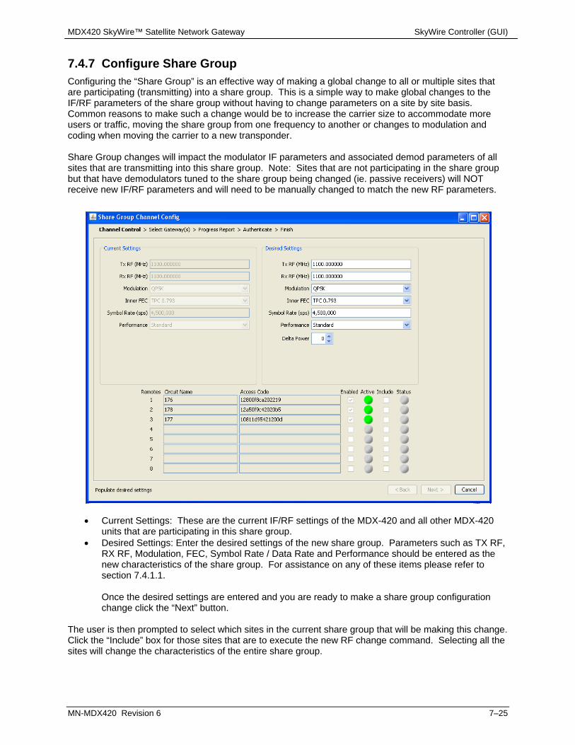
MDX420 SkyWire™ Satellite Network Gateway SkyWire Controller (GUI)
MN-MDX420 Revision 6 7–25
7.4.7 Configure Share Group Configuring the “Share Group” is an effective way of making a global change to all or multiple sites that are participating (transmitting) into a share group. This is a simple way to make global changes to the IF/RF parameters of the share group without having to change parameters on a site by site basis. Common reasons to make such a change would be to increase the carrier size to accommodate more users or traffic, moving the share group from one frequency to another or changes to modulation and coding when moving the carrier to a new transponder. Share Group changes will impact the modulator IF parameters and associated demod parameters of all sites that are transmitting into this share group. Note: Sites that are not participating in the share group but that have demodulators tuned to the share group being changed (ie. passive receivers) will NOT receive new IF/RF parameters and will need to be manually changed to match the new RF parameters.
Current Settings: These are the current IF/RF settings of the MDX-420 and all other MDX-420 units that are participating in this share group.
Desired Settings: Enter the desired settings of the new share group. Parameters such as TX RF, RX RF, Modulation, FEC, Symbol Rate / Data Rate and Performance should be entered as the new characteristics of the share group. For assistance on any of these items please refer to section 7.4.1.1. Once the desired settings are entered and you are ready to make a share group configuration change click the “Next” button.
The user is then prompted to select which sites in the current share group that will be making this change. Click the “Include” box for those sites that are to execute the new RF change command. Selecting all the sites will change the characteristics of the entire share group.

MDX420 SkyWire™ Satellite Network Gateway SkyWire Controller (GUI)
MN-MDX420 Revision 6 7–26
Share Group Configuration Rules: It is a requirement that all sites be “Enabled” (See section 7.4.3) in the share group; are active
and show an active green light on the GUI at the time a share group command is entered for processing. All active sites in the share group need to be informed that a share group change is being requested.
If a site is not presently available and not in the network it must be “Disabled” by unchecking the “Enabled: box (See section 7.4.3) before a share group command will be accepted.
If you select the site the GUI is currently controlling, all other sites in the share group will automatically be selected.
When a sub-set of the total sites in the share group are selected (not all sites) the sub-set is assumed to be moving to an EXISTING alternative share group. You can not move a sub-set of sites to a new frequency location in order to creat a new share group.
Once the share group configuration changes have been made, select “Next”. At this time parameters of the change are sent to each MDX-420 but are NOT EXECUTED. Each device that will be affected by the change must first check that the change is executable and reply with an acceptace or rejection of the change. The “Status” color of each site that is requested to change will then turn either green (accepted) or red (rejected).
By doing this the MDX-420 devices affected ensure that they have the proper options and configuration to execute the command. For example, asking all sites to change to a 5Mb data rate to add capacity would require that all sites have the 5Mb data rate option installed. If an “included” site is unable to execute a command or if any of the configuration rules above are not met the user will get a Configuration Error message as seen below:

MDX420 SkyWire™ Satellite Network Gateway SkyWire Controller (GUI)
MN-MDX420 Revision 6 7–27
If all sites affected accept the change the user can click on “Next” to goto the authentication screen:
Depending on the version of SNMP (2 or 3) being run, the user will then be asked for the appropriate community or password to proceed to execution. Once the password is entered click “Next” to execute the command. Upon execution, the network will allow the sites to either create a new share group (all sites only) or move selected sites to another share group (sub-set of sites). WHEN MOVING ALL SITES: If, after roughly 10 minutes, all sites have not properly moved, ALL sites will revert back to their original state. This includes the settings of “Auto Start” (See Section 7.4.1.1 “Auto Start”) again it is HIGHLY suggested that one site and only one site in a share group have Auto Start selected. If no sites in the share group have Auto Start selected and if the Share Group change reverts back to the original settings the network will not automatically re-form. WHEN MOVING A SUB-SET OF SITES: individual sites that properly entered into the new share group will stay and sites that had difficulty will revert to the original share group. If there are sites that for any reason have difficulty with the share group command, sites can always be individually moved as needed without using the Share Group Channel Config.

MDX420 SkyWire™ Satellite Network Gateway SkyWire Controller (GUI)
MN-MDX420 Revision 6 7–28
7.4.8 Configure TCP/IP Settings TCP/IP Settings are all READ ONLY settings from the GUI. These settings are only configurable from the service port J7 serial interface ONLY.
Boot Mode: Determines what IP addresses, gateways and masks will be used by the modem. Under normal operation this should be NONVOL. Other selections typically used in test or in the factory are: DEFAULT, BOOTP, IP TEST. See section 6.2.4.8 for more on this. BootP Server Tag: Only used in BootP Boot Mode and the tag must match the sever’s expected tag. Local Host Name: Local Host Name for the Network
IP MASK {ddd.ddd.ddd.ddd} Decimal Mask The IP Address Mask of the local network. The mask is expressed in a hexadecimal format, and must be a valid TCP/IP Mask. This field should be set before changes are made to the Gateway or Router Address. MODEM IP ADDR {ddd.ddd.ddd.ddd} Decimal Mask The IP Address of the gateway. This address should be consistent for the mask defined. This address is expressed in hexadecimal format. Broadcast and loop back addresses will not be allowed. These are addresses with all subnet bits set to 0’s or 1’s. SERVER IP ADDR {ddd.ddd.ddd.ddd} Decimal Address The IP Address of the Boot Server and the address of the SNMP Trap Server when SNMP is active. If a server is used and there is no local router, this address must be consistent with the gateway address. If a router has been specified, the address is presumed to be reachable via the router. Broadcast and loop back addresses will not be allowed. These are addresses with all subnet bits set to 0’s or 1’s. ROUTER IP ADDR {ddd.ddd.ddd.ddd} Decimal Address The IP Address of the Local Network Router. If a router is present on the local network, this address must be consistent with the IP Mask and the subnet of the gateway. If no router is present, then the address should be set to a foreign address. This address is expressed in hexadecimal format. Broadcast and loop back addresses will not be allowed. These are addresses with all subnet bits set to 0’s or 1’s. Modem Ether Addr {hhhhhhhhhhhh} Displays the Ethernet address of the device. Set at the factory and is a unique identifier for the Ethernet physical interface.

MDX420 SkyWire™ Satellite Network Gateway SkyWire Controller (GUI)
MN-MDX420 Revision 6 7–29
ETHER RATE {10/100 MBPS/Auto Negotiate} The data rate for the local Ethernet Interface. 10/100 Mbps/Auto Sensing – for 10 or 100 Base-T in either half-duplex or full duplex. FTP User ID {XXXXXXXXXXXXXX} The user ID for creating a FTP session. FTP sessions are used to update a unit’s Firmware. Note: It is strongly suggested to use the same FTP User ID for all MDX-420 units in a network. The default user ID is: user FTP Password {XXXXXXXXXXXXXX} The Password for enabling a FTP session. FTP sessions are used to update a unit’s Firmware. Note: It is strongly suggested to use the same FTP Password for all MDX-420 units in a network.The default Password is: password

MDX420 SkyWire™ Satellite Network Gateway SkyWire Controller (GUI)
MN-MDX420 Revision 6 7–30
7.5 Tools Tab The tools tab allows the user to set certertain criteria for ease of use and to update and check the status of the firmware running on the MDX-420 sites in the current share group.
7.5.1 Options Options (Figure 7.5.1) allows for the user to determine if the Carrier Frequency and Throughput control for the burst modulator and burst demodulator.
Carrier Frequency Control: IF or RF. IF indicates L-Band control and RF indicates control using the Satellite uplink and downlink frequencies. This selection will change the way frequencies are displayed and entered in the modulator and demodulator configuration screens.
Statistics Averaging Period (secs): Enter the number of seconds used for the averaging period for all of the display statics.
Throughput Control: Data Rate or Symbol Rate. Selecting the Data Rate control allows the user to set the data throughput for the SkyWire gateway based on the user data rate. Selecting the Symbol Rate control allows the user to set the data throughput for the SkyWire gateway based on the symbol rate of the modulated carrier.
FTP Control: Used to update MDX-420 Firmware (See Section 6.2.4.8 “FTP User ID” and “FTP Password”
Figure 7.5.1 Options Control Screen

MDX420 SkyWire™ Satellite Network Gateway SkyWire Controller (GUI)
MN-MDX420 Revision 6 7–31
7.5.2 Firmware Status The Firmware Status page gives a brief overview of the Firmware that is available to each MDX-420 in the share group. NOTE: The proper FTP User ID and Password must be entered into the Options control screen (see Figure 7.5.1) in order to see the firmware status for each MDX420.
This information tells the user what firmare versions are in the “archive” and “accepted” folders of the MDX-420. This doe NOT tell you what version of firmware is actually running on the MDX-420, only what is available. To know what version is currently running click on the main tab “Configure” and “System” (see section 7.4.5). For more information on how to update firmware over satellite or boot from a specific firmware version please read the white paper: AN/SKYWIRE_FTP Rev. –“SKYWIRE™ GATEWAY M&C UPDATE PROCEDURE USING FTP UTILITY PROGRAM”

MDX420 SkyWire™ Satellite Network Gateway SkyWire Controller (GUI)
MN-MDX420 Revision 6 7–32
7.6 Main Screen / Home Screen The main screen (Figure 7.6), or home screen once logged into a SkyWire MDX-420 contains 4 main sections. 1) Demodulator Status 2) Network Status 3) Event Logs 4) Alarms
Figure 7.6 Main screen
7.6.1 Demodulator Status Screen The Demodulator Status screen that is the upper left portion of the Main Screen, (Figure 7.6) is used to monitor carrier status of the burst demodulators located in the gateway which the SkyWire Controller is logged into. Individual remote data is normalized for relative performance. Carrier composite information is displayed numerically based on the user defined Polling Interval (Section 7.3.1). By using the Graph drop down menu, information about individual sites in the share group can be seen. This information is displayed on a per MDX-420 basis. In this example there are three (3) MDX-420 sites in a single share group. Information per MDX-420 is available as:
% Total IR – Normalized percent of total throughput % CIR – Normalized percent of assigned committed information rate % Max IR – Normalized percent of assigned maximum information rate Total Packets – Total packets received Packet Errors – Total packet errors Carrier Level (dBm) – Receive Carrier level of the burst demodulator Eb/No (dB) – Signal quality of the shared carrier received by the burst demodulator

MDX420 SkyWire™ Satellite Network Gateway SkyWire Controller (GUI)
MN-MDX420 Revision 6 7–33
PER – Packet error rate Some of these drop down graphs, such as the Carrier Level and Eb/No have indicators in red and green on the “Y” axis of the graph to help operators understand if the products are being used in a suggested range (see figures 7.6.1-a and 7.6.1b). These ranges change depending on the data rate, performance, modulation and coding being used.
Figure 7.6.1-a Figure 7.6.1-b
Composite status (located on the right side of each Demod section) does not change regardless of the Graph drop-down and includes information on the carrier as a whole (all sites that are members of a share group treated as a single composite carrier):
Carrier (min) – Carrier level of the active burst demodulator in the share group with the lowest receive carrier level Eb/No (min) – Signal quality indicator of the active burst demodulator in the share group with the lowest Eb/No PPS – packets per second – Statistically averaged snapshot of the total packet per second rate received by the share group. % Total IR – composite throughput PER – composite packet error rate Packet errors – composite packet errors Total packets – composite packets
Figure 7.6.1-c Demodulator Status

MDX420 SkyWire™ Satellite Network Gateway SkyWire Controller (GUI)
MN-MDX420 Revision 6 7–34
7.6.2 Network Status Screen The Network Status display (Figure 7.6.2) is divided into two sections. The TX section is specific to the MDX-420 the operator is currently logged into and shows graphical and numerical status about the information transmitted to the shared carrier. The Demod ”X” Composite section shows the graphical and numeric composite status of all sites on the shared carrier that is associataed with the modulator (see section 7.4.1.1 “Selected Demod”). By using the Graph pull down menu various statistics can be viewed: TX Information: Kbps – Transmitted information rate in Kilobits per second from the MDX-420 pps – Transmitted packets per second from the MDX-420 %CIR - Information rate as a % of configured CIR for the currently logged in MDX-420 % Total IR - Information rate as a % of the total share group total information rate Total packets – Total packets transmitted by the MDX-420 Demod X Composite: Kbps – Received information rate in Kilobits from all units in the share group pps – Received packets per second from all units in the share group %CIR - Information rate as a % of configured CIR for the currently logged in MDX-420 % Total IR - Information rate as a % of the total share group total information rate Total packets – Total packets transmitted by the MDX-420
Figure 7.6.2. Network Status

MDX420 SkyWire™ Satellite Network Gateway SkyWire Controller (GUI)
MN-MDX420 Revision 6 7–35
7.6.3 Alarm Status Screen Alarm summary (Figure 7.6.3) provides the top level view of both current and latched alarms on the gateway which the SkyWire Controller is logged into.
Figure 7.6.3 Alarms (Summary)
To view the details of the individual alarms, double click on either the current or latched alarm and the details will be displayed. Detailed alarms are described in section (7.4.6)
7.6.4 Events Log Screen Event logs (Figure 7.6.4) provides a historical listing of captured events that may be of interest to the user for the gateway since power up or the last clearing of the events for:
Modem – Gateway specific SNMP – Interface related Application – SkyWire Controller program related
Figure 7.6.4 Event Log

MDX420 SkyWire™ Satellite Network Gateway SkyWire Controller (GUI)
MN-MDX420 Revision 6 7–36
7.7 Defining User Access Controls (SNMPv3) Once the SkyWire gateway parameters have been established, the administrator can determine user access controls. Defining and establishing access controls allows the administrator to limit user access to the gateway and the network. Limiting access ensures that network parameters are not arbitrarily placed into unauthorized users. When SNMPv3 is selected, the administrator can assign access privileges to users. They may be configured as Viewers, Operators or Users with administrative access.
Note: Setting up SNMP V3 administrative controls can be done during initial setup of the Network.
7.7.1 Setup Terminal Access parameters Prior to configuring the User Access Control on the SkyWire Configuration Controller software (SkyWire Controller), the administrator must configure the Group Access setting in the SNMP Terminal screens. Refer to Figure 7.7.1. The SNMP Version 3 Terminal screen parameters must be set up first in order to allow access to the gateway with the SkyWire Controller. SNMP Terminal parameters and SkyWire Controller parameters must match. Refer to Section 6 for additional information on accessing the Service port terminal screens.
The gateway is shipped with SNMP Control factory default parameters per Table 7.7.1.
There are three user "Groups" that determine access type for each user. These groups include ADMIN, OPER or VIEWER. Administrator must configure parameters for each group.
VIEWER: Allows the user to view the gateway status. There is no access to Gateway ID or network data. OPERA: Allows the user to view the link status and limited parameter controls. No access to Gateway ID. ADMIN: Full access and control to all menus within the Network.

MDX420 SkyWire™ Satellite Network Gateway SkyWire Controller (GUI)
MN-MDX420 Revision 6 7–37
Figure 7.7.1 SNMP Version 3 Terminal Screen
USER1 USER2 USER3 USER4
ID administrator operator viewer
Group ADMIN OPER VIEWER NO GROUP
AuthP password password password
PrivP password password password
AuthM MD5 MD5 MD5 NONE
PrivM DES DES DES NONE
User Reset
Table 7.7.1 SNMP Version 3 Terminal Default Parameters
Administrator Settings for SNMP Terminal Screens:
ID 1-4: Default names are administrator, operator and viewer. Names can change. Group: ADMIN, OPER, OR VIEWER AuthP: Defined by the administrator and at least 8 characters in length. PrivP: Defined by the administrator and at least 8 characters in length. AuthM: None, MD5 or SHA PrivM: None, DES Reset: Resets the user parameters to the defaulted names listed
Note: Parameters assigned in the Terminal must be the parameters used when logging in with the SkyWire Controller.

MDX420 SkyWire™ Satellite Network Gateway SkyWire Controller (GUI)
MN-MDX420 Revision 6 7–38
7.7.2 Setup SkyWire Controller Access Parameters If the user is currently logged into a SkyWire gateway with the SkyWire Controller, the user must log out and log back in to activate the SNMPv3 controls set in the Terminal menu. In the Login screen, click the button to the right of the Destination Name to configure the SkyWire Controller interface parameters. The Destination Configuration menu will be displayed as shown in Figure 7.7.2-1. Select the originally saved Destination Name in the pull down menu or create a new Destination Name for the gateway. By selecting SNMPv3 for this gateway, the login screen will require SNMPv3 log-in passwords and allow access to the SNMPv3 menus.
WARNING: When SNMPv3 is selected, the unit secures the mesh network by requiring authentication privacy. This verifies that the contents of the messages have not been altered as that the source is authenticated. It also protect against disclosure as ease dropping.
Figure 7.7.2-1 Login Screen – Select SNMPv3
Figure 7.7.2-2 Login Screen for SNMPv3

MDX420 SkyWire™ Satellite Network Gateway SkyWire Controller (GUI)
MN-MDX420 Revision 6 7–39
Terminal (SNMP) SkyWire Controller
ID# Security Name
Group Context Name
AuthP Authentication Password
PrivP Privacy Password
AuthM Authentication Protocol
PrivM Privacy Protocol
Table 7.7.2 Login Screen Names between Terminal and SkyWire Controller
7.7.3 The SNMPv3 Login Menus The SNMPv3 menus allow the user to begin the user access configuration process. Use the factory defaults to access the User Profile Configuration Menus and begin configuring profiles for the administrator and all other users within this gateway. The MDX420 is shipped from factory with the following Login Screen defaults: Menu Names Factory Defaults User profile Name: Viewer, Operator, Administrator Authentication Password: password Privacy Password: password User Profile Name: The default user names are preassigned to allow the administrator initial access to the configuration menus. When user names are created in the next section of the configuration menus, that name will be displayed in the drop down menus. User Profile can have as many profile names as needed. Once user names are created, they will only need to login using the assigned name and passwords given. Password must be a least 8 characters in length. Authentication Password: Use the password created in the SNMP Terminal screen. The password settings between the SkyWire Controller and the Terminal screens have to match in order to work correctly. Refer to the SNMP Terminal Screens in section 6. Password must be a least 8 characters in length. Privacy Password: Use the password created in the SNMP Terminal screen. The password settings between the SkyWire Controller and the Terminal screens have to match in order to work correctly. Refer to the SNMP Terminal Screens in section 6. Password must be a least 8 characters in length.
7.7.4 SNMPv3 User Profile Configuration Select the user profile type in the SNMPv3 Menu and click on the button at the bottom of the Login screen to display the User Profile Configuration screen (Figure 7.7.4-1). In this screen the administrator can create and configure all the users. User Profile Configuration Menus and the factory defaults are listed below:
Menu Names Factory Defaults User profile Name: Viewer/Operator/Administrator Security User Name: Viewer/Operator/Administrator Context Name: Viewer/Operator/Administrator Authentication Protocol: None Privacy Protocol: None
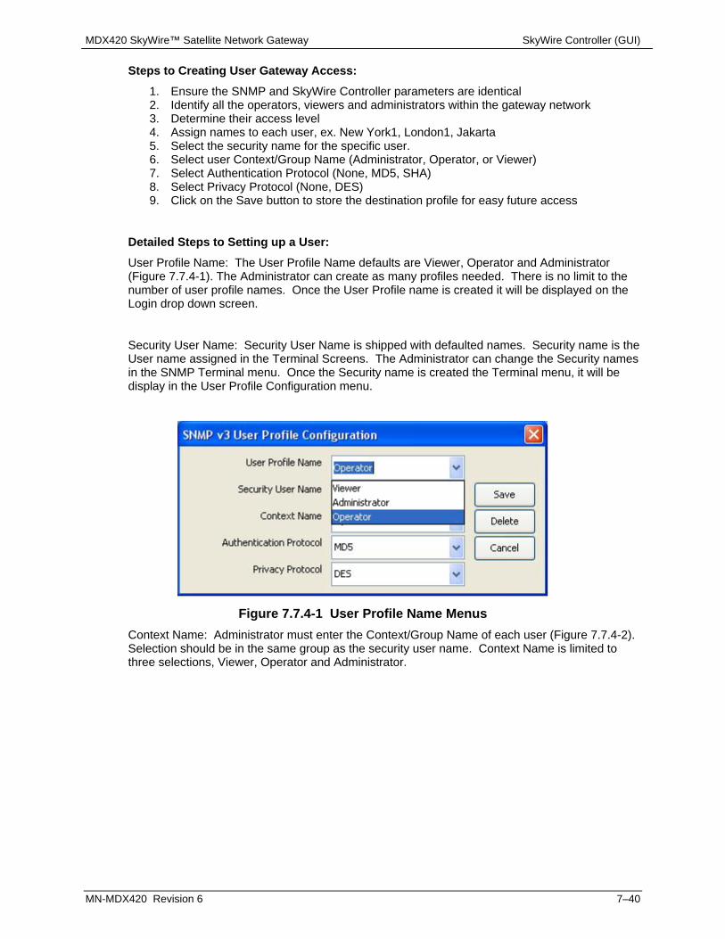
MDX420 SkyWire™ Satellite Network Gateway SkyWire Controller (GUI)
MN-MDX420 Revision 6 7–40
Steps to Creating User Gateway Access:
1. Ensure the SNMP and SkyWire Controller parameters are identical 2. Identify all the operators, viewers and administrators within the gateway network 3. Determine their access level 4. Assign names to each user, ex. New York1, London1, Jakarta 5. Select the security name for the specific user. 6. Select user Context/Group Name (Administrator, Operator, or Viewer) 7. Select Authentication Protocol (None, MD5, SHA) 8. Select Privacy Protocol (None, DES) 9. Click on the Save button to store the destination profile for easy future access
Detailed Steps to Setting up a User:
User Profile Name: The User Profile Name defaults are Viewer, Operator and Administrator (Figure 7.7.4-1). The Administrator can create as many profiles needed. There is no limit to the number of user profile names. Once the User Profile name is created it will be displayed on the Login drop down screen.
Security User Name: Security User Name is shipped with defaulted names. Security name is the User name assigned in the Terminal Screens. The Administrator can change the Security names in the SNMP Terminal menu. Once the Security name is created the Terminal menu, it will be display in the User Profile Configuration menu.
Figure 7.7.4-1 User Profile Name Menus
Context Name: Administrator must enter the Context/Group Name of each user (Figure 7.7.4-2). Selection should be in the same group as the security user name. Context Name is limited to three selections, Viewer, Operator and Administrator.

MDX420 SkyWire™ Satellite Network Gateway SkyWire Controller (GUI)
MN-MDX420 Revision 6 7–41
Figure 7.7.4-2 Context Name Menus
Authentication Protocol: Authentication Protocol provides data integrity and data origin authentication (Figure 7.7.4-3). Hash function MD5 or SHA-1 are supported. Selection must be in the same as selected in the SNMP Terminal screens.
None: Allows the operator to assign the applicable user Access Level group. MD5: Allows the operator to assign the applicable user Access Level group SHA: Allows the operator to assign the applicable user Access Level group
Figure 7.7.4-3 Authentication Protocol Menus
Privacy Protocol: DES is used for encryption providing protection against disclosure of message payload (Figure 7.7.4-4). Selection should be in the same as selected in the SNMP Terminal screens.
None: Allows the operator to assign the applicable user Access Level group DES: Allows the operator to assign the applicable user Access Level group

MDX420 SkyWire™ Satellite Network Gateway SkyWire Controller (GUI)
MN-MDX420 Revision 6 7–42
Figure 7.7.4-4 Privacy Protocol Menus
Click on the Save button to store the User in the User Profile Configuration Menu
User name and setting will be available on the Login Screen.

MDX420 SkyWire™ Satellite Network Gateway Technical Specifications
MN-MDX420 Revision 6 8–1
Chapter 8. Technical Specifications
SkyWire™ MDX420 Performance Acquisition Modulation User Data Network Typical Performance & TPC FEC Rate Range Threshold BER 1E-8 Enhanced QPSK .710 328k - 12.7m 2.9dB 3.5dB
Enhanced QPSK .793 366k - 14.2m 3.3dB 3.8dB
Standard QPSK .793 378k - 14.7m 3.4dB 4.4dB
Enhanced 8PSK .793 537k - 20.9m 6.5dB 7.6dB
Standard 8PSK .793 555k - 21.6m 7.8dB 9.0dB
Modulator
Modulation: QPSK (8PSK Optional)
L-Band Tuning Range: 950 to 1750 MHz in 1 Hz Steps
Impedance: 50 Ohm
Connector: N-Type (50 Ohm)
Return Loss: 10 dB Minimum
Output Power: 0 to -25 dBm
Output Accuracy: ±1.0 dB Over Frequency and Temperature
Spurious: -55 dBc In-Band
-45 dBc Out-of-Band
Harmonics: -45 dBc
On/Off Power Ratio: >60 dB
Symbol Rate Range .256 to 10 Msps in 1 sps steps
FEC: Turbo Product Code .710, .793
Internal Stability: ±280 ppB
±50 ppB (Optional)
Optional BUC Power: 3.3 Amps @ 24 V Maximum
2.8 Amps @ 48 V Maximum
BUC Reference: 10 MHz, +3 dBm ± 3 dB

MDX420 SkyWire™ Satellite Network Gateway Technical Specifications
MN-MDX420 Revision 6 8–2
Demodulator
Demodulation: QPSK (8PSK Optional)
L-Band Tuning Range: 950 to 2050 MHz in 1 Hz Steps
Impedance: 75 Ohm
Connector: F-Type (75 Ohm) Female
Return Loss: 10 dB Minimum
Input Level: 10 x Log (Symbol Rate) -122 + 12 dB
Total Input Power: -10 dBm or +40 dBc (the lesser)
Symbol Rate Range .256 to 10 Msps in 1 sps steps
FEC: Turbo Product Code .710, .793
Carrier Acquisition Range: ± 5% of the Symbol Rate
LNB DC Power: 500 mA @ 24 VDC Maximum
LNB Reference: 10 MHz, +3 dBm ± 3 dB
Monitor and Control
Ethernet 10/100 Base-T
SNMP V1, V2, and V3
MIB Browser
Radyne Network Configuration GUI
Service Port
Terminal RS-232
Terrestrial Interface
Ethernet 10/100/1000 Base-T
Alarms
One Form-C Relay
Five Open Collector
Environmental
Prime Power: 100 to 240 VAC, 50 to 60 Hz, Auto-sensing
40 Watts Max, Gateway only
200 Watts Max, BUC & LNB Powered
Operating Temperature: 0 to 50° C, 95% Humidity, Non-Condensing
Storage Temperature: -20 to 70° C, 99% Humidity, Non-Condensing
Physical
Size: 19”W x 13”D x 1.75”H
(48.26 x 33.0 x 4.45 cm)
Weight: 7 pounds (3.17 kg)

MDX420 SkyWire™ Satellite Network Gateway Upgrade Procedure
MN-MDX420 Revision 6 A–1
Appendix A. Upgrade Procedure
A.1 Introduction The satellite gateway permits field upgrades to its feature set using the terminal port. Purchased upgrades become part of the gateway’s permanent configuration. Demonstration upgrades enable the optional features for 30 days of evaluation.
A.2 Required Equipment The Gateway is the only equipment required for these procedures.
A.3 Permanent Upgrade Procedure From the Terminal Screen, you can quickly find whether or not the desired feature(s) are supported by the hardware already installed in the gateway. The top line identifies the options and the second line identifies the following options status:
INSTALLED means that the option is already available as part of the gateways feature set. HW & KEY REQ means that additional hardware is required for the option. Contact Comtech for
more information. KEY CODE REQ means that the desired option is available as a Terminal screen upgrade.
Contact Comtech with the Feature ID and desired upgrades. The gateway’s Feature ID can be found in the Terminal Screen System Menu. The 12-digit Unit ID is shown in the System menu. It is 3 sets of 4 digits in a dot-delineated format: 1 2 3 4 . 1 2 3 4 . 1 2 3 4 Your Comtech sales representative will ask you for this number and the desired feature set upgrades when placing your order. After the order has been processed, you receive a 12-digit feature set upgrade code. This code is valid only for the gateway for which it was ordered. Enter this ID code on the Feature ID line item. If the code entered is correct, CODE ACCEPTED appears on the display. Otherwise, INVALID CODE appears.
IMPORTANT Make sure that the upgrade code is entered correctly. After three unsuccessful attempts to enter a code, the Terminal System Menu and demonstration capability are locked out. In that case, set the gateway’s power OFF and ON again to continue.

MDX420 SkyWire™ Satellite Network Gateway Upgrade Procedure
MN-MDX420 Revision 6 A–2
A.4 Demonstration Upgrade Procedure The procedure for enabling a 30-day demo of the options is similar to the procedure used for permanently updating the gateways feature set. The one big difference being that at the end of 30 days, the demo features will automatically be disabled and the gateway will revert to its permanent configuration. From the Terminal Screen, you can quickly find whether or not the desired feature(s) are supported by the hardware already installed in the gateway. The top line identifies the options and the second line identifies the following options status:
INSTALLED means that the option is already available as part of the gateways feature set. HW & KEY REQ means that additional hardware is required for the option. Contact Comtech for
more information. KEY CODE REQ means that the desired option is available as a Terminal screen upgrade.
Contact Comtech with the Feature ID and desired upgrades. The gateway’s Feature ID can be found in the Terminal Screen System Menu. The 12-digit Unit ID is shown in the System menu. It is 3 sets of 4 digits in a dot-delineated format: 1 2 3 4 . 1 2 3 4 . 1 2 3 4 Your Comtech sales representative will ask you for this number and the desired feature set upgrades when placing your order. After the order has been processed, you receive a 12-digit feature set upgrade code. This code is valid only for the gateway for which it was ordered. Enter this ID code on the Feature ID line item.
IMPORTANT Make sure that the upgrade code is entered correctly. After three unsuccessful attempts to enter a code, the Terminal System Menu and demonstration capability are locked out. In that case, set the gateway’s power OFF and ON again to continue.
If the code entered is correct, CODE ACCEPTED appears on the display. Otherwise, INVALID CODE appears. DEMO MODE indicates that the option is has been temporarily activated and is now available for evaluation as part of the gateways feature set.
NOTE At the end of the demonstration period, when the gateway reverts to its permanent configuration, an interrupt in traffic will occur. This happens even if a demo-enabled feature is running. Operator intervention is required to restore the data paths. To avoid this interruption in service, cancel the demonstration at any time by following the instructions in the “Canceling Demonstration Mode” section.

MDX420 SkyWire™ Satellite Network Gateway Upgrade Procedure
MN-MDX420 Revision 6 A–3
A.5 Canceling Demonstration Mode
IMPORTANT Once a demonstration has been canceled, it cannot be restarted with the old demonstration code. To restart a demonstration, you must first request a new demonstration code.
At any time, you can cancel a demonstration and return the gateway to normal operation. To cancel a demonstration from the Terminal:
1. Go to the System Menu. 2. Select Cancel Demos. 3. Press ENTER.
The gateway stops the demonstration immediately. The feature set reverts to the permanent configuration. The Mod and Demod Test LEDs stop flashing

MDX420 SkyWire™ Satellite Network Gateway Upgrade Procedure
MN-MDX420 Revision 6 A–4
BLANK PAGE .
MDX420 SkyWire™ Satellite Network Gateway TCP/IP Ethernet Setup
MN-MDX420 Revision 6 B–1
Appendix B. TCP/IP Ethernet Setup
B.1 Introduction The gateway supports SNMP protocol. Utilization of the protocol is dependent upon proper set up of the TCP-IP menus though the Network Configurator. This document is to be used only as a guideline for setting up the TCP-IP menus. Contact the IT manager for proper guidance to ensure setup is compatible with the local LAN.
B.2 TCP/IP Network Configuration TCP/IP setup must be done in conjunction with the Network Configurator setup. Each gateway requires proper configuration with the correct network settings. Contact the IT manager for a valid IP address mask, Gateway, server and router IP addresses.
1. Boot Mode: This allows for the selection of the operating boot mode for the TCP / IP. Several selections are available and are described below. When configuring the gateway for Web Browser, Boot Mode must be set to “NON-VOL”. A brief description of the available selections are:
a. Default: If the Ethernet interface is not to be used, select this mode. No IP Address or mask changes will be allowed while in this mode of operation. The following parameters will be set and will not change until the boot mode is changed. The IP addresses are non accessible addresses.
IP MASK 255.000.000.000 GATEWAY IP ADDR 010.000.000.001 SERVER IP ADDR 010.001.001.001 ROUTER IP ADDR 010.000.001.001
b. BOOTp: When enabled, at boot time, the gateway will use the Bootp Protocol to
automatically get names, masks, and IP Addresses of the gateway, router, and server from the Network Manager. This should be consistent with the tag expected by the users Bootp Server (see the next menu selection for setting the BOOTp TAG). If Bootp is not enabled, the gateway will ignore the BOOTp Tag setting.
c. NON-VOL: This will allow for setting up all required IP Addresses and will store the
information to the non-volatile memory. Upon power cycle, the gateway will restore the saved settings into the correct fields.

MDX420 SkyWire™ Satellite Network Gateway TCP/IP Ethernet Setup
MN-MDX420 Revision 6 B–2
d. IP TEST: The IP Test selection is similar in behavior to the Default selection. When enabled, the following preset parameters will be programmed and will not change until the selection is changed. To edit these parameters, change the boot mode to NON-VOL.
IP MASK 255.255.255.000 GATEWAY IP ADDR 192.168.000.236 SERVER IP ADDR 192.168.000.101 ROUTER IP ADDR 192.168.000.102
IMPORTANT Contact the IT department for guidance to make sure setup is successful. The gateway is shipped from the factory with the Boot Mode configured as IP Test. Verify that the Boot Mode is set for IP Test. To access the gateway via the Ethernet port, set the selection to IP TEST. This sets the IP parameter to an accessible address. To use an alternate address, set the selection to NON-VOL. For example purposes, a new gateway IP address of 172.018.100.205 is used for the remaining of the TCP-IP setup procedure described here.
2. BOOT SERVER TAG: This allows for the selection of the operating boot tag when operating in
the BOOTp Mode. The default setting of 206 is automatically selected when the boot mode is set to ‘DEFAULT’ (factory preset mode).
3. GATEWAY HOST: This displays the gateway Host name, this is a read only display. 4. IP ADDR MASK: This will allow for the entry of the IP Address Mask. This will need to be
entered based on the Network settings. Refer to your IP Administrator if you do not know this address for the correct address setting. Example IP Address Mask setting: 255.255.000.000.
5. GATEWAY IP ADDR: This will allow for the entry of the Gateway‘s individual network IP
Address. Each device on the network will have a unique address. Refer to the IT administrator for the correct address setting. Example Gateway IP Address setting: 172.018.100.215.
6. SERVER IP ADDR: This allows for the setup of the Network Server IP Address. This section
refers to the Host that will be used to optionally boot the gateway on power-up and is the SNMP Trap Server. This IP Address needs to be consistent with the Gateway IP Address. Broadcast and loop back addresses will not be allowed. Example Server IP Address setting: 172.018.004.250.
7. ROUTER IP ADDR: This allows for the setup of the Network Router IP Address. If a router is
present on the local network, and it is to be used, this address must be consistent with the IP Address Mask and the subnet of the gateway. If no router is present, then the address should be set to a foreign address. Broadcast and loop back addresses will not be allowed. Router not used example: Router IP Address setting: 010.000.001.001.
8. GATEWAY EADDR: This displays the Gateway (Unit) Ethernet Address. The Gateway Ethernet
Address is configured at the factory. It is a unique Comtech equipment identifier Address. Example: 0010650903EB
9. ETHER RATE: This displays the current Ethernet port data rate. If multiple rates are available,
then a selection can be made to specify the Ethernet port data rate (10BaseT). Example Ethernet port Data Rate: 10 MBPS/HD

MDX420 SkyWire™ Satellite Network Gateway TCP/IP Ethernet Setup
MN-MDX420 Revision 6 B–3
B.3 Network Configuration Summary If the above steps were followed and the information was entered, then the following would be the TCP / IP configuration summary for a ‘no router specified’ setup:
1. Boot Mode = NON-VOL 2. Bootp Server Tag = 206 3. Gateway Host= MDX420 4. IP Address Mask = 255.255.0.0 5. Gateway IP Address = 172.18.100.215 6. Server IP Address = 172.18.4.250 7. Router IP Address = 010.000.001.001 8. Gateway Ethernet Address= 0010650903EB 9. Ethernet Rate = 10 MBPS/HD
B.4 Ethernet Test
B.4.1 Connecting the Gateway Ethernet Cable to a Network Link 1. Connect the Network Switch (Hub) to the Gateway Ethernet port (J9) using standard
RJ-45 to RJ-45 10BaseT (CAT-5) Cables as shown below.
Ethernet Network Connection
B.4.2 Connecting the Gateway Ethernet Cable Directly to a Computer (without a Network)
The user can directly connect to the equipment without connecting to a network. This will often occur at remote sites where a network is not available. To connect, the user will need an Ethernet Crossover (Null) cable. The pinout for this cable is as follows,
RJ45 Connector A RJ45 Connector B
Pin #1 Pin #3
Pin #2 Pin #6
Pin #3 Pin #1
Pin #4 Pin #4
Pin #5 Pin #5
Pin #6 Pin #2
Pin #7 Pin #7
Pin #8 Pin #8

MDX420 SkyWire™ Satellite Network Gateway TCP/IP Ethernet Setup
MN-MDX420 Revision 6 B–4
The Computer TCP/IP must be properly configured in order to obtain connectivity. The following set-up procedure can be used as a guide to aide in this setup. The following instructions apply only to Windows 2000 or XP Classic. 1. Click on the Start Button. Select Settings and click on the Control Panel Icon. Double click
the Network Connections Icon. 2. Select the Local Area Connection icon for the applicable Ethernet adapter. Usually it is the
first Local Area Connection listed. Double click the Local Area Connection. Click on the Properties icon.
Local Area Connection Status Box
3. Make sure that the box next to the Internet Protocol (TCP/IP) is checked. Highlight
Interconnect Protocol (TCP/IP) and click on the Properties button.

MDX420 SkyWire™ Satellite Network Gateway TCP/IP Ethernet Setup
MN-MDX420 Revision 6 B–5
Local Area Connection Properties Box
4. Select “Use the following IP Address”. Enter in the IP Address that is offset by 5 or so
numbers from the equipment address (the computer and the equipment that it is connecting to can not have identical addresses) and Subnet Mask ( this is identical to the subnet mask programmed into the equipment) into the corresponding fields. Click the OK button to complete the PC Configuration. Note: some computers may require that the computer be restarted for the changes to take effect.
Internet Protocol (TCP/IP) Properties Box
5. To reconnect the computer to a network, select the “Obtain an IP address automatically”
selection in the screen shown above.

MDX420 SkyWire™ Satellite Network Gateway TCP/IP Ethernet Setup
MN-MDX420 Revision 6 B–6
B.4.3 Testing the Ethernet connection using the Ping Program (Optional) To verify that connectivity and settings are correct, use the Ping command to report if the Host (Equipment) is correctly responding. This is accomplished by opening the MSDOS Command Prompt and executing a Ping command as shown in the following example. 1. Open MSDOS Command Prompt. The Screen will display:
Microsoft Windows XP [Version 5.1.2600] (C) Copyright 1985-2001 Microsoft Corp.
2. At the Command Prompt Enter “ping 172.18.100.215” (Enter the IP Address of the equipment to be tested). The screen will display:
Microsoft Windows XP [Version 5.1.2600] (C) Copyright 1985-2001 Microsoft Corp. C:\> ping 172.18.100.215
3. If the ping is successful the screen will display:
C:\>ping 172.18.100.215 Pinging 172.18.100.215 with 32 bytes of data: Reply from 172.18.100.215: bytes=32 time=109ms TTL=64 Reply from 172.18.100.215: bytes=32 time<1ms TTL=64 Reply from 172.18.100.215: bytes=32 time=2ms TTL=64 Reply from 172.18.100.215: bytes=32 time=123ms TTL=64 Ping statistics for 172.18.100.215: Packets: Sent = 4, Received = 4, Lost = 0 (0% loss), Approximate round trip times in milli-seconds: Minimum = 0ms, Maximum = 123ms, Average = 58ms
4. If the ping is unsuccessful the screen will display:
C:\>ping 172.18.100.215 Pinging 172.18.100.215 with 32 bytes of data: Request timed out. Request timed out. Request timed out. Request timed out. Ping statistics for 172.18.100.215: Packets: Sent = 4, Received = 0, Lost = 4 (100% loss),
Check the following items that may lead to the unsuccessful response: a. Verify that the correct cables are connected to the Ethernet port and that they are
secured. b. The Link Light is illuminated. c. The IP Address that is used matches the Gateway’s IP Address. d. The Server and Gateway are on the same subnet.

MDX420 SkyWire™ Satellite Network Gateway SkyWire QoS
MN-MDX420 Revision 6 C–1
Appendix C. SkyWire Quality of Service
C.1 Introduction SkyWire provides the same Quality of Service functionality as many commercially available QOS switches costing hundreds of dollars. The four prioritized queues and programmable ingress and egress policies give network administrators the ability to control how the various types of real-time and non real-time services flow through the network. And because all of the QOS determinations and queuing are performed at line speed, there is no additional delay through the network.
C.2 The Relationship Between IP and Other Protocols Despite being a layer 2 Ethernet device, SkyWire provides Quality of Service functionality that works at layer 3, the IP level. Processing IEEE tags when they are available and interpreting the QOS information inherent in the IP header when they're not.
Protocol Relationships
Telnet FTP TFTP
TCP UDP . . .
Internet Protocol ( I P )
Local Network Protocol
. . .
This IP level functionality is compatible with various methods of implementing QOS including:
The use of an optional IEEE 802.3ac tag containing IEEE 802.1p priority information The Type of Service field or Differentiated Services field contained in an IPv4 header The Traffic Class field (RFC 2460) contained in an IPv6 header

MDX420 SkyWire™ Satellite Network Gateway SkyWire QoS
MN-MDX420 Revision 6 C–2
By making use of the information inherent in the data stream, SkyWire offers Quality of Service when no other QOS source is available. While at the same time, providing transparent operation that won't interfere when external equipment is used for traffic shaping. The following paragraphs provide additional detail on the various types of QOS information available in the data stream and how SkyWire uses them to route the data to the appropriate queue.
C.2.1 IEEE Tagged Packets When a packet contains an optional IEEE tag, SkyWire uses the priority information contained in the tag to determine the appropriate queue. The IEEE tag supports 8 priorities with 7 being the highest and 0 being the lowest. The following diagrams illustrate the format of the IEEE tag and the mapping of the various priorities to the four available queues.
IEEE Tag Format
Second Octet0x00
Priority3 bits
CFI1 bit
VID (start)4 bits
VID (continued)8 bits
First Octet0x81
Network QueuePriority 6 and 7
Critical QueuePriority 4 and 5
Immediate QueuePriority 2 and 3
Routine QueuePriority 0 and 1
QueueManager
Packets Out
IEEE Tag Prioritized Traffic Flow
Packets In

MDX420 SkyWire™ Satellite Network Gateway SkyWire QoS
MN-MDX420 Revision 6 C–3
C.2.2 IPv4 Packets with a Type of Service field (RFC 791) When a packet doesn't contain an IEEE tag, and it's an IPv4 packet with a Type of Service field (TOS), SkyWire uses the information contained in the TOS Precedence field to determine the appropriate queue. The Type of Service field is contained in the second byte of the IPv4 header and supports 8 levels of precedence with 7 (Network Control) being the highest and 0 (Routine) being the lowest. The following diagrams illustrate the format of the IPv4 Type of Service information and their mapping to the available queues. Please note, in IPv4, the Type of Service field and Differentiated Services field (discussed in the next section) occupy the same location in the IP header, therefore, only one of these fields will be present in any particular IPv4 header.
IPv4 Type of Service Field
Precedence3 bits
D1 bit
Reserved2 bits
T1 bit
R1 bit
R = Reliability T = Throughput D = Delay
Precedence 111 = Network Control 110 = Internetwork Control 101 = Critical / ECP 100 = Flash Override 011 = Flash 010 = Immediate 001 = Priority 000 = Routine
Network QueuePrecedence 6 and 7
Critical QueuePrededence 4 and 5
Immediate QueuePrecedence 2 and 3
Routine QueuePrecedence 0 and 1
QueueManager
Packets In Packets Out
IPv4 Type of Service Traffic Flow

MDX420 SkyWire™ Satellite Network Gateway SkyWire QoS
MN-MDX420 Revision 6 C–4
C.2.3 IPv4 Packets with a Differentiated Services field (RFC 2474) When a packet doesn't contain an IEEE tag, and it's an IPv4 packet with a Differentiated Services field (DS), SkyWire uses the information contained in the Differentiated Services Code point field to determine the appropriate queue. The Differentiated Services field is contained in the second byte of the IPv4 header and supports 64 codepoints with 63 being the highest priority and 0 being the lowest. The following diagrams illustrate the format of the IPv4 Differentiated Services information and their mapping to the available queues. Please note, in IPv4 the Type of Service field (discussed in the previous section) and Differentiated Services field occupy the same location in the IP header, therefore, only one of these fields will be present in any particular IPv4 header.
IPv4 Differentiated Services Field
Differentiated Services Codepoint6 bits
Reserved2 bits
Network QueueCodepoints 48 - 63
Critical QueueCodepoints 32 - 47
Immediate QueueCodepoints 16 - 31
Routine QueueCodepoints 0 - 15
QueueManager
Packets Out
IPv4 Differentiated Services Traffic Flow
Packets In

MDX420 SkyWire™ Satellite Network Gateway SkyWire QoS
MN-MDX420 Revision 6 C–5
C.2.4 IPv6 Traffic Class (RFC 2460) When a packet doesn't contain an IEEE tag, and it's an IPv6 frame, SkyWire uses the information contained in the Traffic Class field to determine the appropriate queue. The Traffic Class field is contained in the 1st and 2nd bytes of the IPv6 header and supports 64 priority levels with 63 being the highest and 0 being the lowest. The following diagrams illustrate the format of the IPv6 Traffic Class field and the mapping of the various priorities the available queues.
IPv6 Traffic Class Field
Traffic Class2 bits
IP Version4 bits
Traffic Class4 bits
Reserved2 bits
Flow Label4 bits
Network QueuePriorities 48 - 63
Critical QueuePriorities 32 - 47
Immediate QueuePriorities 16 - 31
Routine QueuePriorities 0 - 15
QueueManager
Packets In Packets Out
IPv6 Traffic Class Flow

MDX420 SkyWire™ Satellite Network Gateway SkyWire QoS
MN-MDX420 Revision 6 C–6
C.3 Programmable Ingress Policies SkyWire provides the network administrator with the following QOS settings that control how the incoming data is routed to the four prioritized queues.
C.3.1 Normal QOS When Normal QOS is selected, the determination of traffic priority and queuing is based on information contained in the Ethernet packet as follows: When a packet contains an IEEE802.3ac Tag (this tag is optional), SkyWire uses the IEEE802.1p priority information embedded in the Tag. When a packet does not contain the optional Tag, priority is determined using the IPv4 Type of Service / Differentiated Service field or IPv6 Traffic Class field
C.3.2 Port Based QOS When Port Based QOS is selected, SkyWire ignores and QOS information embedded in the headers and instead priority and queuing is based on the port on which the traffic arrives. Ethernet packets arriving on Data Port J3 have the highest priority and those arriving on Data Port J4 have the lowest. This type of QOS is typically used when the operator wants to control bandwidth allocation based upon the data ports. Port Based QOS can also be used to create a FIFO like operation where the data is transmitted in the exact order it is received. This can be extremely useful when traffic shaping equipment or crypto devices are used with SkyWire. In these cases, only one of the data ports (J3 or J4) would be utilized.

MDX420 SkyWire™ Satellite Network Gateway SkyWire QoS
MN-MDX420 Revision 6 C–7
C.3.3 Programmable Egress Policies SkyWire provides the network administrator with the following QOS settings that control how the data is routed out of the four prioritized queues and into the burst modulator.
C.3.4 Fair Weighted Queuing A fair weighted priority scheme allows higher priority traffic to move quickly through the system, while at the same time insuring that lower priority traffic isn't stalled indefinitely. When Fair Weighted queuing is selected, packets will be transmitted at a rate of 8, 4, 2, and 1 from the highest to lowest priority queues respectively.
Network QueueVoice
Network Controls
Critical QueueVideo
Controlled Load
Immediate QueueExcellent Effort
Best Effort
Routine QueueBulk Traffic
8 x Output
4 x Output
2 x Output
1 x Output
QueueManager
Packets In Packets Out
Fair Weighted Traffic Flow
C.3.5 Strict Priority Queuing A strict priority scheme means that the highest priority traffic will always be transmitted first, even if it means that the lower priority traffic is stalled indefinitely. When Strict Priority queuing is selected, packets in the highest priority queue will be transmitted until that queue is empty. At that time, packets from the next highest priority queue will be transmitted until it is either empty or a higher priority packet arrives. If a higher priority packet arrives before a lower priority queue is empty, it will immediately go to the head of the line and be the next packet transmitted. Care needs to be taken when selecting this option as it is entirely possible that data in a lower priority queue might never be transmitted.

MDX420 SkyWire™ Satellite Network Gateway SkyWire QoS
MN-MDX420 Revision 6 C–8
C.4 Additional capabilities In addition to the aforementioned QOS capabilities, the SkyWire Ethernet interface provides the following additional functionality.
C.4.1 Automatic Learning and Aging The Automatic Learning and Aging function allows SkyWire to be connected to a network without requiring extensive setup and programming by the operator. The learning process insures that local LAN traffic stays on the local LAN and that only traffic that is not destined for other equipment on the local LAN gets forwarded over the satellite link. The aging process allows equipment to be shut off, moved, or even completely removed from the network without tying up resources or requiring operator intervention. For instance, a particular user might carry a laptop from remote office to remote office and use it to check their e-mail back at the corporate office. The apparent movement of the laptop's MAC address from one position in the network to another is automatically handled by SkyWire. The learned address database maintained by SkyWire can hold up to 1024 MAC addresses. When a new LAN address is learned, it is placed in the database and an aging timer is started. Then, every time this learned address is heard from, its aging timer is reset and restarted. Finally, when the learned address has not been heard from for more than 5 minutes, it is removed from the database. All of the processing required for learning, searching, and aging is handled at line speed and without any unnecessary delay at startup. SkyWire also performs this automatic learning and aging function on its satellite WAN side. Learning the MAC addresses it receives via the satellite, and only outputting those destined for its LAN and those whose destination is still unlearned. This feature is particularly useful in mesh applications as it prevent unnecessary traffic from flooding every LAN in the mesh.
C.4.2 Satellite Packet Error Checking Packet error checking is a standard part of any terrestrial Ethernet system and is performed using the CRC contained in the Ethernet wrapper. When a CRC error is encountered, the packet is discarded by the router, switch, hub, or other device in which the error was detected. SkyWire uses a similar methodology over the satellite link where bit errors result in a corrupted packet with a bad CRC. And for the majority of the situations, the standard process of discarding these packets when they are encountered is the preferred methodology as the packet can simply be retransmitted. However, there are some cases where the end device would rather receive the erred packet than no packet at all. Scenarios involving cryptography or where the end device has additional error correction capability are examples of two such situations. For these customers, SkyWire provides the ability to turn off the satellite packet error checking and packets with bit errors will be output with a valid CRC so that they will pass through any routers or switches in between the gateway and the receiving device.

MDX420 SkyWire™ Satellite Network Gateway SkyWire QoS
MN-MDX420 Revision 6 C–9
C.4.3 A Daisy Chain Capability For large networks that require more than 4 carriers, the ability to daisy chain multiple SkyWire Gateways together provides a simple upgrade path. As your network grows, an addition SkyWire Gateway with up to four burst demodulators can be added to the chain without having to buy additional blades for your router or update the routing table to allow for multiple return paths. From your routers point of view, there will still only be a single one wire path to and from all of the destinations. Despite the fact that the outbound satellite path and some of the satellite return paths go through two boxes.
C.4.4 In-band Control For users who wish to monitor and control the remote end of a link, SkyWire provides an internal connection between the normal data path and the M&C. When this capability enabled, the Ethernet SNMP commands and responses to the far side ride along with the rest of the data traffic. At the far end they are internally passed to and from the M&C without requiring an external connection between the data port and the M&C port. Security for the control information that is riding along with the user traffic is provided by using SNMP version 3. For users who never want to mix their control information with user traffic, disabling this feature breaks the internal connection. In this case, Ethernet control of the M&C can only be accomplished by using one of the M&C RJ-45 Control ports on the gateway.
C.4.5 Internal Buffer and Flow Control Throttle SkyWire provides 120K bytes of internal data storage for buffering of Ethernet traffic. When this buffer is almost full, if flow control is enabled, SkyWire will attempt to slow down the incoming terrestrial data to prevent the buffer from being overrun. It does so using industry standard backpressure on half duplex links and an IEEE 802.3x Pause Frame on full duplex links. Together the combination of the buffer and flow control can provide an effective rate exchange and throttle between the Ethernet ports and the satellite link.

MDX420 SkyWire™ Satellite Network Gateway SkyWire QoS
MN-MDX420 Revision 6 C–10
C.4.6 Auto Everything Ethernet ports The auto crossover, auto polarity, auto negotiation functionality on the SkyWire Ethernet ports provide true “plug and play” connectivity and eliminates the need for special cabling.
C.4.6.1 Auto Crossover SkyWire automatically determines whether or not it needs to cross over between pairs so that external crossover cables are not required. When interoperating with a device that can’t automatically adjust for crossover, Skywire makes the necessary adjustments prior to commencing auto-negotiation. When interoperating with a device that implements MDI/MDIX crossover, a random algorithm as described in IEEE 802.3 section 40.4.4 determines which device performs the crossover.
C.4.6.2 Auto Polarity SkyWire automatically detects and corrects for polarity errors on the receive pairs in 1000Base-T and 10Base-T modes. In 100Base-T mode, the polarity does not matter.
C.4.6.3 Auto Negotiation SkyWire automatically negotiates with its link partner to determine the speed and duplex at which to operate. If the link partner is unable to auto-negotiate, SkyWire utilizes a parallel detect mode to determine the speed of the link partner and then operates in half-duplex at the appropriate rate.
C.4.6.4 Transparent Operation Because SkyWire is completely transparent to the applications that are being run, you don’t have to worry about whether or not they will work over SkyWire. The answer is yes. Whether it’s a VoIP call, or a DHCP server application, or a VPN to the office to check e-mail, or simply web-surfing, if it’s transmitted via Ethernet, it will pass transparently though SkyWire from one point to another.
C.4.7 Adding Acceleration, Compression, Network Security, and Traffic Shaping
Today, there are various acceleration, compression, IP security, and traffic shaping solutions available from numerous third party vendors. Some are proprietary implementations, while others are based on open standards such as MIL-STD-2045-44000 and CCSDS 714.0-B-1. Some may even be implemented in your current network and routers. And while different solutions (including none at all) make sense for different types of networks, SkyWire, with its transparent mode of operation is compatible with all of them.


2114 WEST 7TH STREET TEMPE ARIZONA 85281 USA 480 • 333 • 2200 PHONE
480 • 333 • 2161 FAX