Embed Size (px)
Citation preview

Page 1 of Chapter W2 – Surface Developments
WEB CHAPTER 2 – SURFACE DEVELOPMENTS
Surface development is a full size layout of an object drawn on a plane. Some objects are made of flat sheet metal. When the sheet is cut as per this layout, folded and joined together, it takes the shape of an object. Orthographic projections of the object are drawn first and then the development is drawn. Parts made of thin sheet are some times reinforced by embedding a wire in its open edge called Wiring. Alternately single or double hemming is done for stiffening the edge. Allowances are to be provided for joining or hemming etc.. The edges are joined together by soldering a lap joint or by flat lock seaming. Flat surfaces like that of a box or singly curved surfaces as those of cylinder or cone, which can be developed are called developable surfaces. Following are some well known development methods for these surfaces. The development method to be used depends upon type of surface and what data is available. Straight line development: It is used if surfaces of the object are flat and true size of each side is known e.g. a box or a prism. Sides of the object can be laid in successive order. Radial line development: It is used if true length of an edge is shown in front view and top view shows the lengths of edges of base line e.g. a cone. Parallel line development: It is used for singly curved object. The curved surface is opened to form a flat plane e.g. a cylinder. Doubly curved surface like that of a sphere is non-developable. These surfaces can be approximately developed by any one of the following methods: Zone method: The surface is divided into horizontal zones and each zone is developed as a frustum of a cone. Gore method: Surface is divided into a number of equal vertical sections. Each section is considered as an arched segment. Triangulation method: Surface is divided into small triangles joined at their sides e.g. a football is made by joining many hexagonal pieces. A hexagon is a set of 6 triangular pieces.
Surfaces in AutoCAD are shown by many contour lines along the edges to form a mesh. System variables SURFTAB1 and SURFTAB2 are used to set the number of lines for axes of the mesh. Following commands can be used to create some predefines surfaces practically in no time. The name of command is indicative of what it can create. AI_ is to be prefixed before every name e.g. AI_BOX, AI_WEDGE, AI_PYRAMID, AI_CONE, AI_SPHERE, AI_DOME, AI_DISH and AI_TORUS. Following commands can be used to create a surface by different methods: 3DMESH Creates a surface through the specified coordinates of each node point of the mesh. REVSURF Creates an axis symmetric surface by revolving a path curve about an axis. RULESURF Creates a surface connecting two straight or curved defined edges. TABSURF Creates a surface by moving a path curve along a direction vector. EDGESURF Creates a surface connecting four straight or curved defined edges. Following commands can be used as drafting aids and inquiry: MEASURE To put marks on an object at specified distance AREA To find the area and perimeter of a specified boundary DIST Provides information about distance and angle between two specified points Surface development using a AutoCAD system is almost same as manual drafting method. However computer provides easy procedures for construction and hence takes lesser time than manual drafting.

Page 2 of Chapter W2 – Surface Developments
W2.1 INTRODUCTION Many objects like metal boxes, tin cans, funnels, ducts, elbows etc. are made from flat sheet, which is cut, folded and joined to give the required shape. To get the exact size, orthographic projections of the object are first drawn, then a surface development is made to show the shape of the complete surface called development. The required shape called as pattern is first drawn on a thin sheet to the actual shape. Materials used for making patterns are card board, plastics, fiber board, wood and metal sheets. This pattern is then traced along the outer profile and pasted on the metallic sheet from which the part is to be made. When the material is cut out of the developed shape and bent at the lines marked, an object similar to the desired object is obtained. For example, the development of a cylinder is a rectangle. Wrap a rectangular sheet to join any two opposite sides and a hollow cylinder is formed. Thus in the process of development, the true size of all the faces is found so that all the lines lie in one common plane and then bent and joined at their common edges to form a three dimensional object. To understand the process of making a development, take an example of a triangular box open at top as shown in figure W2.1A and its orthographic views in figure W2.1B. It has three rectangular faces A, B and C and a triangular base D. This box can be opened out from any one of the edges so that all the faces lie in one plane. When opened at edge formed by faces A and C, it appears as shown in figure W2.1C. This is known as surface development. The dashed lines shown in the development are the lines where the bending is to be done.
(A)Pictorial view (B) Orthographic views (C) Surface development
Figure W2.1 A triangular hollow box
The base D can be attached at the bottom edge of any face A, B or C. Figure W2.2 shows development if the base is attached to base A or Base C. Choice has to be made for the one which gives minimum material waste when many parts are to be cut from a big sheet.
Figure W2.2 Alternative locations of the base of a triangular hollow box
The open edges are then joined by sheet metal joints (Section W2.2), soldering or brazing.

Page 3 of Chapter W2 – Surface Developments
W2.2 JOINTS USED IN SHEET METAL In addition to soldering and brazing, special joints as shown in figure W2.3 can also join sheet metals. It can be seen that in all the joints, a seam of bend is given to the plates and then hooked together to form a joint. Any convenient method can be selected.
Figure W2.3 Sheet metal joints
W2.3 REINFORCEMENT OF FREE EDGES Sheet metal is of very less thickness and has sharp edges, which can cause injury to the worker or user. Hence hemming is done by single or double bend at the free boundary edges (figure W2.4). This bend reinforces the sheet and also safeguards against injury. Sometimes wiring is done in which a wire is embedded while bending the free edge to impart more strength and thickness. An allowance of 2.5 times the wire diameter can be provided extra at the free end for making this wired bead (figure W2.5).
Figure W2.4 Reinforcement in sheet metal parts
W2.4 JOINT AND REINFORCEMENT ALLOWANCES No allowance for the material required for the joint has been indicated in the developments shown in figure W2.1. In an actual development, allowance of extra material has to be provided at the edges to form a lap joint. Refer figure W2.5 showing the allowance for a lap joint and for hemming.
Figure W2.5 Joint allowance in developments

Page 4 of Chapter W2 – Surface Developments
NOTE: No joining allowance has been shown in all the problems of developments discussed hereafter. In actual practice it has to be taken into consideration.
W2.5 TYPES OF DEVELOPMENTS Flat surfaces like that of a box or singly curved surfaces as those of cylinder or cone can be exactly developed. Such a surface is called a developable surface. For doubly curved surfaces like sphere exact surface development is not possible, hence approximate development is done. Such a surface is called non-developable surface. W2.6 DEVELOPABLE SURFACES Following are some well known development methods for developable surfaces:
• Straight line development • Radial line development • Parallel line development
W2.6.1 STRAIGHT LINE DEVELOPMENT This method is used if surfaces of the object are flat and true size of each side is known e.g. a box, a prism and a pyramid. The sides of the object are laid in successive order in one plane. Figure W2.6 shows a rectangular prism having four sides, a top and a bottom. The base is of size LxW and sides are of height of H mm. When all the four faces are opened in one plane, it has a total length of (2L + 2W) and height H mm. The top and bottom of each of LxW size can be attached to any common edge.
Figure W2.6 Development of a rectangular prism EXAMPLE 1 (HEXAGONAL PRISM) Draw development of a hexagonal prism closed at both ends having each side 50 mm width and length 100 mm as shown on left side of figure W2.S1. SOLUTION Each face of the prism is of size 50x100 mm. Draw six rectangles all in a line and attach the hexagonal end to any one edge at front and back of a face as shown on right hand side of figure W2.S1.

Page 5 of Chapter W2 – Surface Developments
Figure W2.S1 Development of a hexagonal prism EXAMPLE 2 (FIVE SIDED PRISM) Draw development of a five sided prism closed at both ends having vertical faces of 50 mm height, base 100 mm, inclined height 70 mm and length 80 mm as shown on left side of figure W2.S2. SOLUTION Draw each face of the prism of size mentioned in figure. The total length of all the faces when opened out in one plane is (W + 2G + 2H) and width as L. The two ends of the pentagonal shape can be attached to any face as shown in figure W2.S2.
Figure W2.S2 Development of a pentagonal prism EXAMPLE-3 (SQUARE PYRAMID) Draw development of a square pyramid that has a square base of each side 100 mm with four isosceles triangles sloping faces that form an apex at top at 100 mm centrally above the base (figure W2.S3A).

Page 6 of Chapter W2 – Surface Developments
SOLUTION It may be noted that the triangular face shown in the front view does not show its true length of the inclined edge due to its inclination. Hence, the actual shape is found by drawing an auxiliary view. The slant height (SH=110) is the distance of the apex from its base line for its auxiliary view. Since the development has to carry the true shape of each face, therefore the triangles for each face have their vertical height as the slant height and not the vertical height of front view. Its development is a square base of each side 100 mm and four isosceles triangles of base 100 mm and height 112 mm. These faces can be joined at each edge of the square base as shown in figure W2.S3B. Dashed lines indicate the position of the bend. Alternatively the inclined faces can be placed side by side and bent along the dashed lines as shown in figure W2.S3C. The base can then be attached to any edge of the inclined face.
Figure W2.S3 Development of a square pyramid EXAMPLE 4 (OBLIQUE PYRAMID) An oblique pyramid has its base 150x100 mm and vertical height 150 mm. Its apex lies vertically above at 30 mm from long edge and 50 mm from short edges of the base (figure W2.S4). Draw its development. SOLUTION For a right pyramid, the fore-shortening effect of the inclined edges due to their inclination is the same for all, but for oblique pyramid it is different for each face as its apex is not above the geometric centre of the base. To draw the development of such a pyramid, the actual length of each inclined face is required. To get these distances, draw a horizontal line XX in the top view passing through the apex O (figure W2.S4). With O as centre and 01 as radius, draw an arc from point 1 to XX line to cut XX at 1”. Take the projection of 1” in the front view at the base line to cut at 1’. Join apex in front view O to 1’. Distance 01’ is the true length at edge O1. Repeat this process for all the points 2, 3 and 4 to cut the base line in front view at 2’, 3’ and 4’ respectively. Transfer the triangular faces 1, 2, 3 and 4 to the rectangular base of the development in the orientation as shown in figure W2.S4B. Apex point O1 can be found by cutting the arcs of actual lengths O1’

Page 7 of Chapter W2 – Surface Developments
and O2’ from points 1 and 2 respectively. Triangle 012 is the development of face 1. Repeat this process for all the other 3 faces to get the full development.
Figure W2.S4 Development of an oblique square pyramid W2.6.2 RADIAL LINE DEVELOPMENT This method is used if true length of an edge is known in front view and top view shows the size of base e.g. a cone. A cone has a circular base with an apex vertically above the base centre. Since the base is circular, it cannot be attached to the slanting face, hence it has to be cut separately and then attached. Also the body of the cone cannot be like the development of the pyramid but it is as shown in figure W2.7. The radius of the development is equal to the slant height (SH), which is the true length of the inclined face. The actual length of the base is (2πR) as shown in figure W2.7. When the fan shaped development is bent, a cone is formed. The angle of the sector 1O1 (α) of the developed view can be found by simple mathematics as: α = 360 R/SH (where SH is slant height of the cone and R is the base radius). Alternatively, the circular base can be divided into twelve equal parts. The length of each small arc may be cut on the circumference. This is known as triangulation. The development is created by joining all the small triangles side by side e.g. triangle 1O2 with triangle 2O3 and so on.

Page 8 of Chapter W2 – Surface Developments
Figure W2.7 Development of a right circular cone EXAMPLE 5 (OBLIQUE CONE) Draw development of an oblique cone having elliptical base of major axis 115 mm and minor axis 100 mm. Its vertical height is 150 mm and axis is inclined at 60° from vertical axis in vertical plane shifting its apex 31 mm away from the extreme edge of the major axis as shown in figure W2.S5A. SOLUTION An oblique cone does not have its apex above the base centre and hence the slant height changes continuously. Also, the base line is not circular due to unequal lengths. Method of triangulation is used to consider small triangular elements of this cone. The base is an ellipse of major axis X-X and minor axis Y-Y. To draw the development of an oblique cone, follow the steps given below: 1. Draw Front and top view of the cone with elliptical base (figure W2.S5A) 2. Divide the base in 12 parts at 30° interval and number only the lower half from 1 to 7. 3. With O As center and radius as 0-2, draw an arc on major axis to cut X-X at point 2’. Repeat
this process for points 3, 4, 5 and 6. Points 1 and 7 are already on the axis and hence are not affected.
4. Project these points on the base in the front view as 2”, 3” ….6”. Join all these points from the apex O” to form small triangular elements.
5. Line 0-1 and 0-7 show the true length and hence can be measured directly for the purpose of the development. For other elements, find the true length of each element by rotating parallel to the picture plane, i.e., line XX and then take vertical projection to front view. These true lengths are shown as 0’’-2”, 0’’-3”,…0’’-7” etc.

Page 9 of Chapter W2 – Surface Developments
6. With 0” as the center for the development (figure W2.S5B), draw arcs of radii as true lengths to transfer them on the developed view. Make a triangle 0”1”2” in which 0”-1” and 0”-2” are the lengths equal to length 0”-1” and 0”2” of front view and 1”-2” is equal to arc 1-2 of top view.
7. Measure the actual distances of the base from top view and true inclined lengths from front view to create each triangle of the development. All the 12 triangles joined side by side show the development of the cone (figure W2.S5B).
Figure W2.S5 Development of an oblique cone EXAMPLE 6 (HEXAGONAL PYRAMID) Draw development of a hexagonal pyramid. Base edge is of 50 mm and height 110 mm. SOLUTION 1. Draw top view of pyramid as a hexagon with each edge 50 mm and join the corner points with the
center 0. Number the corners as 1, 2, 3, 4, 5 and 6. 2. Draw front view with height 110 mm. Measure the slant height of the inclined edge 0-1.

Page 10 of Chapter W2 – Surface Developments
3. For development draw an isosceles triangle 0-1-2 with lines 0-1 and 0-2 equal to slant height and one side equal to edge (figure W2.S6B).
4. Copy 5 more triangles of same size keeping one edge common to the previous triangle. 5. Attach a hexagonal base to any edge.
Figure W2.S6 Development of hexagonal pyramid
W2.6.3 PARALLEL LINE DEVELOPMENT When a cylinder is opened along its axis, its development is a rectangle. While opening, the two ends of cylinder form two parallel lines hence it is called parallel line development A cylinder has a diameter D and length L. Its top and bottom faces are circular and therefore they cannot be joined to the main body to make it integral. They are to be cut circular separately as shown in figure W2.8. Its curved face when unfolded in one plane is a rectangle of length equal to the circumference of the cylinder (πD) and width same as that of the cylinder length L.
Figure W2.8 Development of a cylinder

Page 11 of Chapter W2 – Surface Developments
W2.7 NON- DEVELOPABLE SURFACES (SPHERE) Sphere is an object, whose surface is curved in both planes, hence, exact development cannot be made, but it can only be approximated. These surfaces can be developed by any one of the following methods discussed below. W2.7.1 ZONE METHOD: The surface is divided into horizontal zones marked A, B, C and D and each zone is developed as a frustum of a cone as shown in figure W2.9A. The method to draw each frustum of cone is same as given in section W2.6.2. Slant height of the cone is taken as the size of the zone e.g. 1-2. The center C1 is the intersection of extenension of line 1-2 with the central axis. The radial distance R1 is shown zig zag as the center C1 is not the actual center but far off from here. Similarly C2 is intersection of extension of line 2-3 and central axis and so on. The development of each zone is shown in figure W2.9B.
(A) Sphere divided in 8 zones (B) Development of each zone
Figure W2.9 Development of a Sphere W2.7.2 GORE METHOD Surface of the sphere is divided into a number of equal sections say 12 equal parts of 30° intervals in the vertical plane and in 6 divisions in horizontal plane (figure W2.10A). Each section is an arch shaped sector as shown in figure W2.10B. Mark the points as per the distance given in figure W2.10. Join all the points by a smooth curve. Twelve such elements are needed to form a sphere of the given radius. Only three are shown here.

Page 12 of Chapter W2 – Surface Developments
(A) Sphere (B) Development
Figure W2.10 Development of a sphere W2.7.3 TRIANGULATION METHOD Surface is divided into small triangles joined at one of its side e.g. a football is made by joining many hexagon pieces. A hexagon is a set of 6 triangular pieces (figure W2.11) It is divided into small elements for the purpose of development. Smaller the elements, closer it is to the actual shape. Some types of elements that can be considered are shown in figure W2.11. Such type of elements can be seen in a football that is composed of small elements of typical shapes.
Figure W2.11 Elements for a sphere

Page 13 of Chapter W2 – Surface Developments
W2.8 OBJECTS CUT BY A PLANE Development of prisms is not affected if the cutting plane is at right angle to the axis, except that its length gets reduced. But if a prism is cut by an inclined plane, the development gets changed. W2.8.1 RECTANGULAR PRISM When a rectangular prism is cut by an inclined plane, its development depends upon as to how it is placed. The easiest case is when face of the prism lies in the principle plane (figure W2.12). Development of a prism with inclined top is shown in figure W2.12. Draw the base line of length (2L + 2W). Draw vertical lines as edges of the prism at distances L and W. The smaller faces have height h1 and bigger faces h2. The other two faces have top lines as inclined lines. The rectangular base can be attached at the bottom of any face. The actual shape of the top face is a rectangle but length is more due to its inclination. This can also be drawn with any of the top face of the development. If the object is open at the top, the top face need not be drawn.
(A) Prism (B) Development
Figure W2.12 Rectangular prism cut by inclined plane (one face aligned with picture plane) If the face of the prism is not parallel to the principle plane as shown in figure W2.13, the cutting plane cuts each vertical edge of the prism at different heights as h1, h2, h3 and h4. Procedure for the development of an inclined prism is similar as discussed in sectionW2.8.1. 1. Draw the base line and mark points 1, 2, 3, 4 and 1 again at the joining edge. These points are
to be marked at distances of W and L alternately. 2. Draw the vertical lines at these points. Since the vertical edges of the prism are parallel to the
principle plane, the heights shown in the front view are the true heights at the cutting point. 3. Take horizontal projections from the front view to cut the vertical lines on the development.
Mark the intersections of the respective points as 1’, 2’, 3’, 4’ and 1’. 4. Join all these points to form the four sides of the prism. Attach the rectangular base of size
LxW to any of the bases at the bottom line. 5. Draw the auxiliary view of the top face and then copy the same at any top edge, say 2’-3’.
Alternately, taking 2’ as centre and 1’-2’ as radius, transfer the length of the inclined edge 1’-2’ for the top view. Similarly, transfer the distance 3’-4’ for the top view as shown by arrows.

Page 14 of Chapter W2 – Surface Developments
(A) Prism (B) Development
Figure W2.13 Rectangular prism cut by inclined plane (face not aligned with picture plane) EXAMPLE 7 (HEXAGONAL PRISM CUT BY INCLINED PLANE) A hexagonal prism with each edge of the base as 50 mm is cut by an inclined plane such that it cuts the extreme edges at a slant height of 95mm and 40 mm (left side of figure W2.S7). Draw its development. SOLUTION The procedure for the development of a hexagonal prism is the same as that for a rectangular prism. Draw the orthographic views first and then transfer the heights of each edge. The top auxiliary view is not exactly hexagonal. Draw the auxiliary view in the direction of A for the development of the top view and then attach at any of the top edges as shown in figure W2.S7.

Page 15 of Chapter W2 – Surface Developments
(A) Hexagonal prism (B) Development
Figure W2.S7 Development of a hexagonal prism cut by an inclined plane W2.8.2 RECTANGULAR PYRAMID When a pyramid cut by a horizontal plane at height H from the base the slant height becomes the height of development at the center line. Solved example 8 demonstrates the development of such a pyramid. EXAMPLE 8 – (RECTANGULAR PYRAMID CUT BY A PLANE) A pyramid with base 160x120 mm has vertical height of apex as 142 mm, It is cut by a plane parallel to its base at a vertical height of 95 mm. Draw its development. SOLUTION To draw the development, follow the steps given below: 1. Make a rectangular base of size 160x120 mm (figure W2.S8A). 2. Make isosceles triangles at each line of the base of height equal to slant height of the pyramid
for the respective edges. It may be noted that the apex is not at an axial height 142 mm from the base in the developed view but equal to the slant height.
3. Cut these triangles at a slant height from the base (location of cutting plane of each inclined face).
4. Draw the other boundary of the inclined faces by drawing lines at right angles to the axes up to the inclined edges.

Page 16 of Chapter W2 – Surface Developments
Figure W2.S8 Rectangular pyramid cut by a horizontal plane EXAMPLE 9 (SQUARE PYRAMID CUT BY INCLINED PLANE) A square pyramid with base of 160x80 mm and slant height 170 mm is cut by an inclined plane at slant height of 50 mm at one face and 15 mm on other face as shown in figure W2.S9. Draw the orthographic views and its development. SOLUTION 1. Draw the square base PQRS of size 160x80 mm with dashed lines. Dashed lined indicate the
position of the bend. 2. Draw four isosceles triangles X1PS, Y1PQ, X2QR and Y2SR of height 170 mm at each side of
the base. Note that the slant height is taken as axial height for development. 3. Mark points 1 and 2 on X1-X2 line at distance h1 and h2 from the dashed lines of the base.
Page 17 of Chapter W2 – Surface Developments
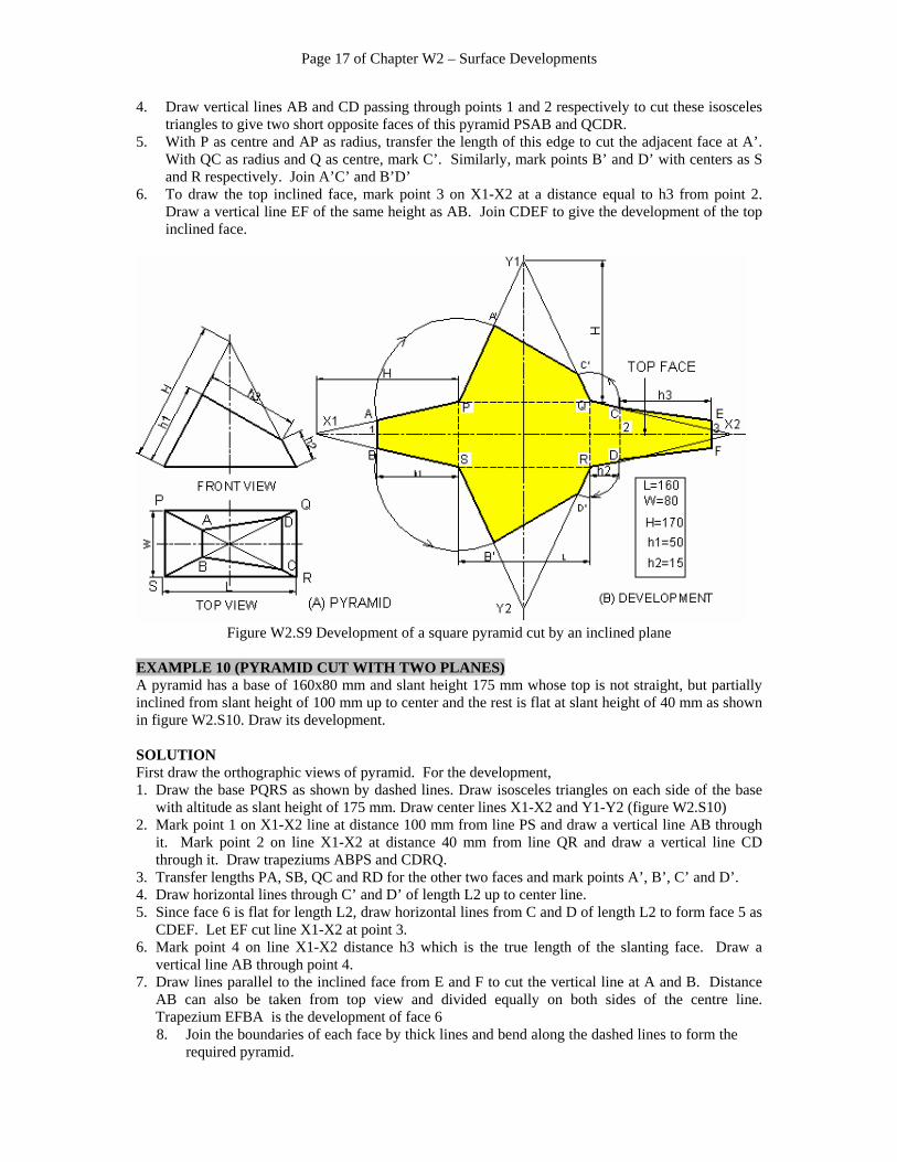
4. Draw vertical lines AB and CD passing through points 1 and 2 respectively to cut these isosceles triangles to give two short opposite faces of this pyramid PSAB and QCDR.
5. With P as centre and AP as radius, transfer the length of this edge to cut the adjacent face at A’. With QC as radius and Q as centre, mark C’. Similarly, mark points B’ and D’ with centers as S and R respectively. Join A’C’ and B’D’
6. To draw the top inclined face, mark point 3 on X1-X2 at a distance equal to h3 from point 2. Draw a vertical line EF of the same height as AB. Join CDEF to give the development of the top inclined face.
Figure W2.S9 Development of a square pyramid cut by an inclined plane
EXAMPLE 10 (PYRAMID CUT WITH TWO PLANES) A pyramid has a base of 160x80 mm and slant height 175 mm whose top is not straight, but partially inclined from slant height of 100 mm up to center and the rest is flat at slant height of 40 mm as shown in figure W2.S10. Draw its development. SOLUTION First draw the orthographic views of pyramid. For the development, 1. Draw the base PQRS as shown by dashed lines. Draw isosceles triangles on each side of the base
with altitude as slant height of 175 mm. Draw center lines X1-X2 and Y1-Y2 (figure W2.S10) 2. Mark point 1 on X1-X2 line at distance 100 mm from line PS and draw a vertical line AB through
it. Mark point 2 on line X1-X2 at distance 40 mm from line QR and draw a vertical line CD through it. Draw trapeziums ABPS and CDRQ.
3. Transfer lengths PA, SB, QC and RD for the other two faces and mark points A’, B’, C’ and D’. 4. Draw horizontal lines through C’ and D’ of length L2 up to center line. 5. Since face 6 is flat for length L2, draw horizontal lines from C and D of length L2 to form face 5 as
CDEF. Let EF cut line X1-X2 at point 3. 6. Mark point 4 on line X1-X2 distance h3 which is the true length of the slanting face. Draw a
vertical line AB through point 4. 7. Draw lines parallel to the inclined face from E and F to cut the vertical line at A and B. Distance
AB can also be taken from top view and divided equally on both sides of the centre line. Trapezium EFBA is the development of face 6 8. Join the boundaries of each face by thick lines and bend along the dashed lines to form the
required pyramid.

Page 18 of Chapter W2 – Surface Developments
(A) Pyramid (B) Development
Figure W2.S10 Square pyramid cut by two planes
EXAMPLE 11 (TRUNCATED PYRAMID) A hexagonal pyramid has a base of each side 60 mm and slant height of 210 mm at one edge. It is cut by an inclined plane at slant height of 120 mm at one edge and at 45 mm at diagonally opposite edge (figure W2.S11). Draw its development. SOLUTION If a pyramid is truncated by an inclined plane as shown in figure W2.S11, then the initial procedure is the same as that explained for pyramids in Examples 3 and 4. In front view line 01 and 04 are the only true lengths. The rest are not true because of the inclination of the faces. The top face has to be drawn by drawing the auxiliary view as discussed in chapter 9 of the book. Rest of the procedure is same as described earlier, except that the base is hexagonal instead of square or rectangular. Alternate method - Radial line method In this method, it is assumed that all the faces are integral at the inclined faces. Let O be the centre for development. 1. With O as centre and O1 as radius draw an arc. Mark 6 points on this sector, each of length L and
number them from 1 to 6 and 1 (figure W2.S11). 2. Join 1-2, 2-3, etc. to represent the base of development. Draw radial lines from centre O to join
these points 1, 2…6 etc. 3. Get the actual slant distances of the edges by drawing and transfer to development view marked as
point 2”and 3”. 4. Mark points 5’’ and 6’’ by symmetry on the radial lines. Join 1’’, 2’’…6’’ and 1’’ to give the
boundary of the top inclined face.

Page 19 of Chapter W2 – Surface Developments
Figure W2.S11 Development of a truncated pyramid
EXAMPLE 12 (CONE CUT BY INCLINED PLANE) A right circular cone of base diameter 120 mm and slant height 210 mm is cut by an inclined plane as shown in figure W2.S12. The plane cuts the cone at slant height of 125 mm and at 55 mm on the other side. Draw its development. SOLUTION Draw the orthographic views and divide the top view circle into 12 equal parts. Number these points as 1, 2…12. Project these points in the front view and number them from 1 to 7. Points 8 to 12 are on the backside and hence not visible in the front view. Join all these points with apex in the front view. These lines cut the inclined plane. Draw the development of full cone on the side of the front view by the method discussed earlier in section W2.6.2. Let one edge of the development be parallel to the slant height of the cone for the ease of transfer of the radial distances. The boundary of the development for the base may also be numbered as 1, 2 ,3 …12 and 1.

Page 20 of Chapter W2 – Surface Developments
To draw the development of the top inclined face, draw horizontal lines in front view from intersecting points to touch the slant edge. Transfer these true lengths for getting points of intersection of the arctual lines with the radial lines for the respective points. Join them by a smooth curve to give the boundary of the top inclined face. Alternately, if the numbers on the arc for the base are changed from 1-1 to 7 - 7 then the development shape is different. Although the area is the same, but while cutting many pieces from one sheet, one development may lead to lesser wastage than the other. Hence the best development is the one, which gives minimum wastage of material.
Figure W2.S12 Development of a right circular cone cut by an inclined plane
Page 21 of Chapter W2 – Surface Developments
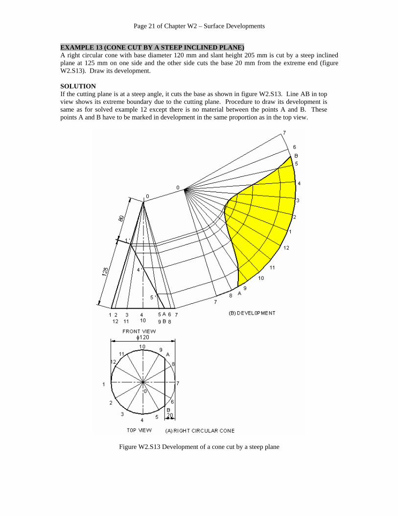
EXAMPLE 13 (CONE CUT BY A STEEP INCLINED PLANE) A right circular cone with base diameter 120 mm and slant height 205 mm is cut by a steep inclined plane at 125 mm on one side and the other side cuts the base 20 mm from the extreme end (figure W2.S13). Draw its development. SOLUTION If the cutting plane is at a steep angle, it cuts the base as shown in figure W2.S13. Line AB in top view shows its extreme boundary due to the cutting plane. Procedure to draw its development is same as for solved example 12 except there is no material between the points A and B. These points A and B have to be marked in development in the same proportion as in the top view.
Figure W2.S13 Development of a cone cut by a steep plane

Page 22 of Chapter W2 – Surface Developments
W2.8.3 CYLINDER CUT BY A PLANE EXAMPLE 14 (CYLINDER CUT BY AN INCLINED PLANE) A cylinder of diameter 110 mm is cut by an inclined plane at a height of 60 mm on one side and 130 mm on opposite side (figure W2.S13). Draw its development. SOLUTION 1. Draw a horizontal line 1-1 of length as the circumference of the cylinder and divide in 12
equal parts. Number them 1 to 12 and 1.Draw vertical lines on each point 2. Divide top view also into 12 equal parts and number them as 1 to 12 3. Draw vertical projections from the top view to the inclined plane to cut at points 1’, 2’, etc. 4. Draw horizontal projections from this inclined plane to cut the vertical lines of development at
1’’, 2’’, etc. Draw a smooth vertical curve joining all these numbers.
Figure W2.S14 Development of a cylinder cut by inclined plane
The bottom is exactly circular of radius R. The top elliptical end can be drawn as an auxiliary view by the method discussed in chapter 10. It is an ellipse of minor axis as D and major axis as the length of the inclined face. EXAMPLE 15 (CYLINDER CUT BY TWO PLANES) A cylinder of diameter 110 mm and height 95 mm is cut by two inclined planes. Both planes pass through center and one slopes down by 30 degrees while the other at 45° (figure W2.S15). It is desired to draw the development of the curved surface of cylinder. SOLUTION First draw the orthographic views. For the development, follow the following procedure. 1. Divide the top view into 12 equal parts and number them from 1 to 12. 2. Draw vertical projections from these points to cut the inclined faces at 1’, 2’, etc. 3. Draw the base line of length πD. Divide it into equal parts and mark them as 1, 2…12, 1 and
draw vertical lines over them. 4. Take horizontal projections from points 1’, 2’, etc. from the front view. Wherever these lines
cut the vertical lines of the development view, mark the intersections as 1’’, 2’’, etc. 5. Join all these points by a smooth curve to show the boundary of the top edge for the curved
face.

Page 23 of Chapter W2 – Surface Developments
Figure W2.S15 Development of a cylinder cut by two inclined planes W2.9 DEVELOPMENT OF TRANSITION PIECES Transition pieces are used to connect two openings of different shapes, say, rectangular, circular or elliptical to circular, rectangular or square etc. in the same axis or any inclined axis. Ends of these pieces can have typical shape and hence they are developed by method of triangulation. Figure W2.14 shows a transition piece whose top is a rectangle and bottom is a circle. The object can be divided into 8 inclined faces. Faces 1, 3, 5 and 7 are isosceles triangles while faces 2, 4, 6 and 8 are triangles with curved boundary at one edge. Before drawing the development, following facts may be noted: 1. Its total periphery at the top is 2L + 2W (L is length and W is width of rectangular opening). 2. Its total periphery at the bottom will be 2πR. (R is the radius of circular opening) 3. Height of faces 1 and 5 is the slant height Hs which is different than height of faces 3 and 7. To draw the development of the transition pieces, first draw the orthographic views. Divide the top view into 8 parts as shown in figure W2.14. Divide the top circle into 12 equal parts and number them. Find the true length of each point, as each point is inclined at a different angle. It is shown by the side of the front view. It is drawn by rotating each point up to line X1-X2 and then taking projections up to front view. Draw each face in its true shape with their sides as common sides in the same sequence. The top rectangular band of uniform height of P can be attached to the faces 1, 3, 5 and 7 as shown in the development.

Page 24 of Chapter W2 – Surface Developments
Figure W2.14 Development of a transition piece

Page 25 of Chapter W2 – Surface Developments
W2.10 SURFACES AND AUTOCAD AutoCAD has many commands to create surfaces, but there is no command to directly create the development of surfaces. This section is included here to appraise the students about the tools available to create different types of surfaces. However, the tools described in Chapter 2 can be helpful to draw developments easily and quicly. In CAD, flat surfaces are displayed by edge lines, while curved surfaces are displayed in the form of segments or a mesh. The number of lines in the mesh are set by SURFTAB1 and SURFTAB2 system variables. Commands for drawing surfaces can be given by any one of the following methods: • On the Menu bar, click Draw and from a pull‐down menu choose the option
Surfaces. A sub‐menu on the side of the pull‐down menu appears. Click on the required option.
• On the Surfaces toolbar, click on the desired icon (Figure W2.15). • On the command line, type a command and press Enter. W2.11 SURFACES TOOLBAR There are 16 icons on the surfaces toolbar (Figure W2.15) . The function of each is mentioned below. The first two icons are for creating only faces in space.
1 2 3 4 5 6 7 8 9 10 11 12 13 14 15 16
Figure W2.15 Surfaces toolbar
1. 2D SOLID Creates a flat three‐ or four‐sided face in a plane of the curent UCS. 2. 3DFACE Creates a three‐ or four‐sided flat face in the space. Predefined standard 3D surfaces can be drawn by clicking on the following icons (Figure W2.16): 3. BOX Draws a 3D box of six flat surfaces 4. WEDGE Draws surfaces of a right‐angled wedge, one face tapering along the X axis 5. PYRAMID Draws surfaces of a pyramid with a three‐ or four‐sided base and
sides with an apex, or a ridge or a four‐sided top

Page 26 of Chapter W2 – Surface Developments
6. CONE Draws surface of a cone or a tapered or plane cylinder of specified base and top radii and height
7. SPHERE Draws a spherical surface 8. DISH Draws the lower half surface of a sphere 9. DOME Draws the upper half surface of a sphere 10. TORUS Draws a surface like a tube of a car Non‐standard surfaces are generated by other methods. Select an icon according to the information available for the surface.
11. EDGE Does not draw any surface, but hides the edges on the rear side of object 12. 3DMESH Draws a surface from the specified vertices of the nodal points of the mesh 13. REVSURF Draws an axisymetric surface of by revolving a profile about an axis 14. RULESURF Draws a surface from two specified edges of the surface 15. TABSURF Draws a surface by moving a 2D object along a specified direction 16. EDGESURF Draws a surface from four specified edges of the surface W2.12 PREDEFINED SURFACES There are eight predefined surfaces which are shown below in Figure W2.16 below:
Box Wedge Pyramid Cone
Sphere Dome Dish Torus
Figure W2.16 Predefined surfaces in AutoCAD

Page 27 of Chapter W2 – Surface Developments
W2.12.1 BOX Click the box icon shown above. Specify a corner of the box followed by its length, width, height and a rotation angle. The prompt sequence to create a box with one corner at the origin and of 120‐mm length, 80‐mm width and 60‐mm height is shown below: Command:AI_BOX ↵ Type command or click the Box icon shown above. Specify corner point of box: 0, 0, 0 ↵ Specify coordinates of one corner. Specify length of box: 120 ↵ Specify length of the box along the X axis and press Enter. Specify width of box or [Cube]: 80 ↵ Specify width of the box along the Y axis
(default option) or type C for Cube option and press Enter.
Specify height of box: 60 ↵ Specify height of the box along the Z axis and press Enter. Specify rotation angle of box about Z axis or [Reference]: 0 ↵
If the box is to be rotated, type an angle otherwise type 0 and Enter
NOTE: The command for all surfaces are to be prefixed by AI_. For example, a BOX
command is to create a solid box and AI_BOX command is used to create only outer surface of a box.
W2.12.2 WEDGE AI_WEDGE command draws a right angled wedge with sloped face tapering along the X axis. Type the command at command line or click the Wedge icon shown above. The following is an example of prompt sequence for a wedge of 60‐mm length, 40‐mm width and 30‐mm height. The corner of the wedge is specified as (100,100,0). The length is aligned along the X axis and rotation angle is specified as zero. Command: AI_WEDGE ↵ Type command or click the Wedge icon shown above. Specify corner point of wedge: 100, 100, 0 ↵ Specify coordinates of the corner. Specify length of wedge: 60 ↵ Specify length of wedge along X axis and press Enter. Specify width of wedge: 40 ↵ Specify width of the wedge and press Enter.

Page 28 of Chapter W2 – Surface Developments
Specify height of wedge: 30 ↵ Specify height of the slanting face and press Enter. Specify rotation angle of wedge about Z axis <0>: 0 ↵ W2.12.3 PYRAMID A pyramid usually has 4 sides with an apex point above the base. AutoCAD offers 4 types of pyramids shown in Figure W2.17. Using AI_PYRAMID command or clicking on the Pyramid icon shown above can create four different types of pyramid surfaces mentioned below: `
a. Pyramid A four‐sided base with an apex at the top (Figure W2.17A). b. Tetrahedron A triangular base with an apex (Figure W2.17B) c. Ridged pyramid A four‐sided base with a ridge on the top (Figure W2.17C) d. Truncated Pyramid A four‐sided base with a four‐sided top (Figure W2.17D)
(A) Pyramid (B) Tetrahedron (C)Ridge pyramid (D)Truncated pyramid
Figure W2.17 Types of Pyramids Command: AI_PYRAMID ↵ Type command or Click the Pyramid icon Specify first corner point for base of pyramid: Specify coordinates of point 1 and
press Enter. Specify second corner point for base of pyramid: Specify coordinates of point 2 and press Enter. Specify third corner point for base of pyramid: Specify coordinates of point 3 and press Enter. Specify fourth corner point for base of pyramid or [Tetrahedron]:
Specify coordinates of point 4 and press Enter or type T and press Enter for Tetrahedron.
Specify apex point of pyramid or [Ridge/Top]: Type T for Top or R for Ridge option and press Enter.

Page 29 of Chapter W2 – Surface Developments
If T is typed for Top option (Points 5, 6, 7 and 8 are points on top surface) AutoCAD prompts: Specify first corner point for top of pyramid: Specify coordinates of point 5 and
press Enter Specify second corner point for top of pyramid: Specify coordinates of point 6 and press Enter. Specify third corner point for top of pyramid: Specify coordinates of point 7 and press Enter. Specify fourth corner point for top of pyramid: Specify coordinates of point 8 and press Enter. W2.12.4 CONE Type AI_CONE command or click the Cone icon shown above to create a cone with a circular base. (Figure W2.18). The curved surface is shown by a number of converging lines. The number of lines are specified by the number of segements at the last prompt of the command. If the top radius (R2) is given as zero, a cone is drawn (Figure W2.18A). If the top radius is specified, a frustrum of a cone is drawn (Figure W2.18B). If the top radius is same as the base radius (R1), it draws a cylinder (Figure W2.18C). Specifying the top radius greater than the base radius inverts the frustrum of a cone (Figure W2.18D).
R2= 0 R1 > R2 R1 = R2 R1 < R2 A. A cone B. A frustom of a cone C. A cylinder D. An inverted frustrum of a cone
Figure W2.18 A 3D cone with different options

Page 30 of Chapter W2 – Surface Developments
The following is the prompt sequence to draw a right circular frustrum of a cone with a height of 60 mm and the center point of its base at (0,0,0). Base and top radii are 30 mm and 10 mm respectively Command: AI_CONE ↵ Type command or click the cone icon. Specify center point for base of cone: 0, 0, 0 ↵ Specify coordinates of center of the
base. Specify radius for base of cone or [Diameter]: 30 ↵ Specify base radius (R1) and
press Enter. Specify radius for top of cone or [Diameter]: <0>: 10 ↵ Specify top radius (R2) and
press Enter. Specify height of cone: 60 ↵ Specify height of the top and press Enter. Enter number of segments for surface of cone<16>: ↵ Press Enter to accept 16
segments.
W2.12.5 SPHERE A spherical surface can be drawn by typing AI_SPHERE command at the command line or by clicking the Sphere icon shown above. The display is in the form of small segements. The number of these segements in longitudinal (joining north to south pole) and latitudinal (circumferential) directions are to be specified at the prompts. The following prompts appear. Command: AI_SPHERE ↵ Type command and press Enter or click sphere
icon. Specify center of sphere: Specify coordinates of center of the sphere. Specify radius of sphere or [Diameter]: Specify radius or and press Enter. Enter number of longitudinal segments for surface of sphere <16>: ↵
Press Enter or type a new value and press Enter. Enter number of latitudinal segments for surface of sphere <16>: ↵
Press Enter or type a new value and press Enter. .
Prompts for DOME and DISH command are similar to SPHERE command except that the latitude segments are half in number than the sphere. The Dome is the upper half of sphere while Dish is the lower half of the sphere.

Page 31 of Chapter W2 – Surface Developments
W2.12.6 TORUS Torus is a shape similar to that of a tube of a car. It is defined by two radii values; one for the radius of torus which is from the center of the torus to the outside of the tube and the other, as the radius of the tube (Figure W2.16). The prompt sequence for this command is: Command: AI_TORUS ↵ Type command and press Enter or click the Torus icon. Specify center of Torus: Specify coordinates of the center and press Enter. Specify radius of torus or [Diameter]: Enter value of radius of torus or type D to specify diameter. Specify radius of tube or [Diameter]: Enter value of radius of tube or type D to specify diameter. Enter number of segments around tube circumference <16>: ↵ Press Enter to accept the default number of segments. Enter number of segments around torus circumference <16>: ↵ Press Enter to accept default number of segments. W2.13 NON‐STANDARD SURFACES Surfaces other than predefined standard can be created by other commands as shown in Figure W2.19. The command to be used depends upon as to what data is available. The following sections describe such commands.
A. 3D MESH B. REVSURF C. RULESURF D. TABSURF E. EDGESURF
Figure W2.19 Non‐standard surfaces
W2.13.1 3DMESH With this command, irregular surfaces can be created which are open in both M and N directions (Figure W2.19A). . First, specify M and N values to determine the number of the vertices (M x N). The vertices are numbered in the matrix format from (0, 0) to (M‐1, N‐1). Then AutoCAD prompts the coordinates of each vertex as shown below. For M = 4 and N = 4 there are 16 vertices. Specify coordinates of each vertex in 3D format, i.e., X, Y, Z.
Page 32 of Chapter W2 – Surface Developments
Command: 3DMESH ↵ Type command and press Enter or click on the 3DMesh icon.
Enter size of Mesh in M direction: 4↵ Type a numerical value for M in the mesh. Enter size of Mesh in N direction: 4↵ Type a numerical value for N in the mesh. Specify location for vertex (0,0): Specify coordinates of the vertex, e.g. 0,0,5. ……… Specify coordinates of each vertex. ……… Go on specifying coordinates of vertices Specify location for vertex (3,3): Specify coordinates of the last vertex. A surface is generated passing through all the specified vertices. 13.13.2 AXIS‐SYMMETRIC REVOLVED SURFACE (REVSURF COMMAND) A revolved surface is created by first defining a path curve or a profile and then the same is rotated about an axis. The path curve is swept about the selected axis to create a surface (Figure W2.19B). Specifying a start angle begins the surface of the revolution at an offset from the generating path curve. The included angle is the distance through which the path curve is swept. Entering an included angle that is less than a full circle prevents the curve from closing. The point used to select the axis of revolution affects the direction of revolution. Selecting one end of the axis of rotation creates the surface in the clockwise direction while selecting at other end creates the surface in the anticlockwise direction. The command sequence is as under: Command: REVSURF ↵ Type command and Enter or click Revsurf icon Select object to revolve: Select a line, arc, circle, or 2D or 3D Polyline. Select object that defines axis of revolution: Select a line Specify start angle <0>: Type a value of the angle or press Enter. Specify included Angle (+=ccw, ‐+cw)<360>: Press Enter for revolving surface by 360 degrees NOTE: Specify a positive value of the angle from the start angle if the path curve is
to be rotated in a counterclockwise direction and negative value for the clockwise rotation direction.
W2.13.3 RULED SURFACE (RULESURF COMMAND) With RULESURF command, a surface is created between two specified edges. Pairs of the object to be used as edges must both be either open or closed. A point can be paired with either an open or a closed object.

Page 33 of Chapter W2 – Surface Developments
To create a ruled surface, first draw the two boundary edges (Figure W2.19C). Then click anywhere on each edge to create the surface. For open curves, AutoCAD starts construction of the ruled surface based on the locations of the points selected on the boundaries. For edges, as closed curves you can specify any two points. It may be noted that this command is to be used after drawing the two boundary edges. The prompt sequence is: Command: RULESURF ↵ Type command and press Enter or click Rulesurf icon Select first defining curve: Click at one of the edge at one end. Select second defining curve: Click at the other edge at same or opposite side.
W2.13.4 TABULATED SURFACE (TABSURF COMMAND) A tabulated surface is created by first defining a path curve and then a line called as direction vector showing the direction of movement of this curve ((Figure W2.19D). The path curve could be a line, an arc, a circle, an ellipse, or polyline. AutoCAD draws the surface starting from this base curve along the path defined by the direction vector line.
Command: TABSURF ↵ Type command and press Enter or click Tabsurf
icon. Select object for path curve: Click on Path curve. Select object for direction vector: Click on the direction vector.
W2.13.5 SURFACE CREATED FROM FOUR EDGES (EDGESURF COMMAND) The EDGESURF command constructs a three‐dimensional mesh from four adjoining edges. First draw four adjoining edges that define the surface patch. The edges can be lines, arcs or splines. The edges must touch at their endpoints to form a closed path. Selection of the four edges can be in any order. The prompt sequence is:
Command: EDGESURF ↵ Type command & press Enter or Click Edgesurf
icon Select object 1 for surfedge edge: Click anywhere on Edge 1. Select object 2 for surfedge edge: Click anywhere on Edge 2. Select object 3 for surfedge edge: Click anywhere on Edge 3. Select object 4 for surfedge edge: Click anywhere on Edge 4.

Page 34 of Chapter W2 – Surface Developments
W2.14 DRAWING AID COMMANDS The following commands help in constructions and give useful information. W2.14.1 MEASURE This command puts a point mark or a block (a set of entities) at a specified distance. Its prompt sequence is as under: Command: MEASURE ↵ Type the command and press Enter Select object to measure: Click on the object to put marks Specify length of segment or [Block]: Specify distance and press Enter W2.14.2 DIST This command provides information about the distance and angles between two specified points. The prompt sequence is as under: Command: DIST ↵ Type the command and press Enter Specify first point: Click on a point from where to measure Specify second point: Click on a point up to which to measure AutoCAD displays the information in the command area. For example, the display is as under: Distance = 107.2151, Angle in XY Plane = 41, Angle from XY Plane = 0 Delta X = 81.4691, Delta Y = 69.6984, Delta Z = 0.0000 Delta X and Delta Y are the distances in X and Y directions respectively. Note: If the information is not visible, bring mouse on the upper side of the
command area. When a double line marker appears, drag it upwards to increase this area.
W2.14.3 AREA AND PERIMETER AREA command calculates the area of a boundary and its perimeter. Its prompt sequence is as under: Command: AREA ↵ Type the command and press Enter Specify first corner point or [Object/Add/Subtract]: Click on a point Specify next corner point or press ENTER for total: Click on next point ………….. This prompt repeats Specify next corner point or press ENTER for total: ↵Press Enter when specify the last
point which is the same as the first point.

Page 35 of Chapter W2 – Surface Developments
AutoCAD displays as under: Area = 2998.8346, Perimeter = 269.4932 EXAMPLE 16 (PERIMETER AND AREA) AIM: Demonstrate the use of drafting tools and the method for surface development. Calculate area and perimeter of the sheet metal. A 90° elbow is to be made by joining two pipes cut at 45°. Using AutoCAD commands, draw development of cylinder with a diameter of 100 mm, and a height of 150 mm as shown in Figure W2.S16. SOLUTION An elbow is made by cutting 2 pipes at 45 degrees and then joining at their inclined edge. Development of both the pipes is shown in the figure below. A. Draw cross section of a pipe 1. Draw a circle using CIRCLE command. Click anywhere on the screen as center
and specify the radius as 50 mm. 2. Use DDPTYPE command to select a point style. Select cross type (third in top
line). Choose point size as 2 units and select radio button as Set size in Absolute units.
3. Use DIVIDE command to divide the circle in 12 parts. Select the circle as object to divide. Specify number of segements as 12. Crosses are marked on the circle.
4. Draw line 1‐7 as diameter using LINE command and complete the rest of the top view.
Page 36 of Chapter W2 – Surface Developments
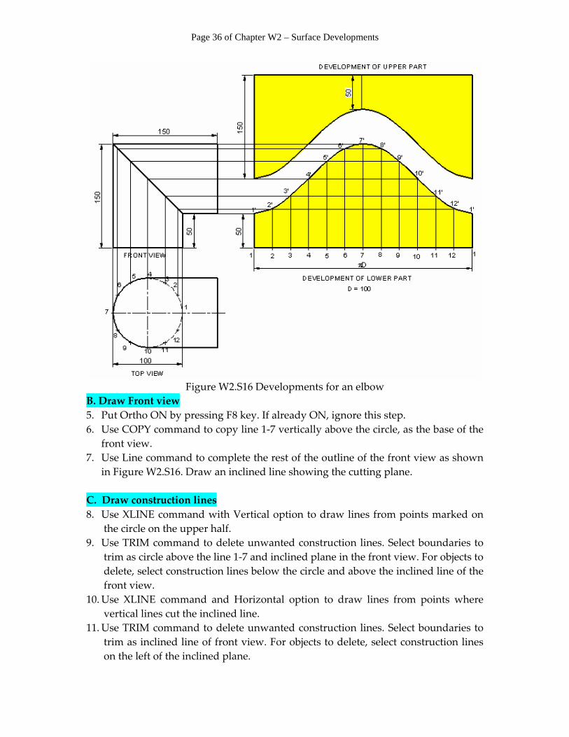
Figure W2.S16 Developments for an elbow
B. Draw Front view 5. Put Ortho ON by pressing F8 key. If already ON, ignore this step. 6. Use COPY command to copy line 1‐7 vertically above the circle, as the base of the
front view. 7. Use Line command to complete the rest of the outline of the front view as shown
in Figure W2.S16. Draw an inclined line showing the cutting plane. C. Draw construction lines 8. Use XLINE command with Vertical option to draw lines from points marked on
the circle on the upper half. 9. Use TRIM command to delete unwanted construction lines. Select boundaries to
trim as circle above the line 1‐7 and inclined plane in the front view. For objects to delete, select construction lines below the circle and above the inclined line of the front view.
10. Use XLINE command and Horizontal option to draw lines from points where vertical lines cut the inclined line.
11. Use TRIM command to delete unwanted construction lines. Select boundaries to trim as inclined line of front view. For objects to delete, select construction lines on the left of the inclined plane.

Page 37 of Chapter W2 – Surface Developments
D. Draw development 12. Draw a horizontal line as development of circumferential length (πD) 314.16 mm
just opposite to base of front view. 13. Use DIVIDE command to divide this in 12 parts. Select the line as object to divide.
Specify number of segements as 12. Crosses are marked on the line. 14. Use XLINE command and Vertical option to draw lines on all points on this base
horizontal line. 15. Use FILLET command with Radius zero, and fillet the respective horizontal and
vertical consturction lines to points 1’, 2’,…..12’ and 1’. 16. Use SPLINE command and select all the points 1’, 2’,…..12’ and 1’ to get the
development of top face of the lower pipe. 17. Use COPY command and copy the SPLINE slightly above the previous curve.
Complete the rest of the outline as shown in Figure W2.S16 for the upper part of the pipe.
E. Getting area and perimeter of development 18. Use AREA command and start selecting all the corner points and development
points in a cyclic order , e.g., 1 (Left)‐1’‐ 2’‐ 3’……….‐ 12’‐ 1’(right) ‐ 1(right) ‐ 1(left). The last point should be the startpoint. Press Enter. AutoCAD displays the information as:
Area = 31400.0000, Perimeter = 794.5275
Page 38 of Chapter W2 – Surface Developments
THEORY QUESTIONS Q 1. What is meant by development? Explain by giving examples. Q 2. What are joining allowances in sheet metal work? How do they affect the
development? Q 3. What is wiring and hemming? Why it is done? Q 4. Differentiate between developable and non‐ developable surfaces. Q 5. What are the different methods for development? Describe any one method. Q 6. Describe the method to draw the development of a hexagonal prism. Q 7. Differentiate between the shapes of development for a pyramid and prism. Q 8. How can you draw the development of a sphere? Describe any one method. Q 9. Explain the procedure to draw the development of a square pyramid cut by
an inclined plane. Q 10. A right circular cone is cut by an inclined plane. Give any two possible shapes
of its development. CAD Q 11. Name the pre‐defined surfaces in AutoCAD Q 12. What are the various commands to create surfaces other than pre‐defined? Q 13. How do you create a cylindrical surface in CAD? Q 14. What is a torus surface? Write the various data to be specified in creating it. Q 15. Describe the use of MEASURE, DIST, AREA and PERIMETER commands.
FILL UP THE BLANK QUESTIONS Fill up the blanks by appropriate word(s). 1. Development for a large sheet metal object is created of the ____________ size as
the object. 2. Putting a wire on the free edge of a sheet metal is called ___________. 3. Seaming is done to ___________ the free edge. 4. Allowances for joining and seaming are ___________ to the development. 5. A sphere has a ___________ surface. 6. The method for development of a cone is ___________ development. 7. Straight‐line method of development can be used for ___________. 8. A cylinder is developed by ___________ line projection method. 9. In zone method to develop a sphere, the surface is divided in zones of
___________ of cone. 10. In ___________ method surface of a sphere is divided in arctual shape. 11. A piece which joins opening of two different cross section is called ___________. CAD 12. Command to create surface of a cylinder is ___________. 13. Torus is a surface like ___________ of a car. 14. Symmetric surfaces can be generated by ___________ command.
Page 39 of Chapter W2 – Surface Developments
15. The command to create a surface from four defined edges is ___________. 16. TABSURF command creates a surface by moving a 2D object in specified
___________. 17. An object can be divided in specified number of segment by
___________command. 18. MEASURE command is used to mark an object at specified ___________. 19. The command to calculate the area of a closed boundary is ___________. 20. Surface commands are prefixed by___________ before their command name.
Page 40 of Chapter W2 – Surface Developments
MULTIPLE CHOICE QUESTIONS Q 1. Development of an object is done to
a. increase its size b. reduce its size c. get the shape of the surface area in one plane d. to calculate surface area
Q 2. For the development of objects made by joining sheet metal joints,
a. the type of the joint should be known b. the type of joint does not make any difference c. the tolerances should be known d. only shape is required
Q3. Number of pieces to make an open rectangular tank of sheet metal with minimum joints is
a. one b. two c. four d. five
Q 4. To make a square pyramid of thin plates, there is only one shape which will make a pyramid. Is this statement true?
a. Yes b. No c. Depends upon the method of manufacturing d. Depends upon the skill of the technician
Q 5. Development of a sphere can not be made by using
a. triangular elements b. trapezopidal elements c. circular elements d. hexagonal elements
Q 6. If a prism is cut by an inclined or curved plane near apex, its development will
a. not be affected b. change according to both position and angle c. change according to position only d. change according to angle only
Q 7. A box cannot be made by the given:
a. length, width, height and center b. base size and height

Page 41 of Chapter W2 – Surface Developments
c. surface area d. corner, length, width and height
Q 8. A tetrahedron is made by using
a. the PYRAMID command b. the RULESURF command c. the CONE command d. none of the above
Q 9. The slant face of the wedge with 0 degree rotation tapers along
a. the X axis b. the Y axis c. the Z axis d. can be along any axis
Q 10. Height of the wedge is
a. along the X axis b. along the Y axis c. along the Z axis d. automatic and proportional to the length
Q 11 Surftab1 system variable is used to
a. create surface models b. create only one surface model c. create tabulated surfaces d. define number of segements in one direction
Q 12. Tube diameter of a torus has to be
a. smaller than the torus diameter b. equal or more c. half of the torus diameter d. one third of the torus diameter
Q 13. A truncated pyramid is made
a. directly by the pyramid command b. by just making the pyramid and then by truncating it using another
command c. by defining a negative height of the pyramid d. by inclined heights and vertical heights
Q 14. A surface is made by selecting four edges by using the command
a. EDGE b. EDGESURF
Page 42 of Chapter W2 – Surface Developments
c. 3DMESH d. POLYFACE
Q 15. Axis symmetric objects are created by the command
a. TABSURF b. 3DMESH c. RULESURF d. REVSURF
Q16. Coordinates of the vertices are given in the command a. RULESURF b. EDGESURF c. 3DMESH d. TABSURF
Answers to Fill up the blank questions 1. same 2. wiring 3. strengthen 4. added 5. undevelopable 6. radial 7. prisms 8. parallel 9. frustom 10.Gore 11. transition piece 12. AI_CONE 13. tube 14. REVSURF 15. EDGESURF 16. direction 17. DIVIDE 18. distance 19. AREA 20. AI_ Answers to multiple choice questions: 1‐c 2‐a 3‐a 4‐b 5‐c 6‐b 7‐c 8‐a 9‐a 10‐c 11‐d 12‐a 13‐a 14‐b 15‐d 16‐c

Page 43 of Chapter W2 – Surface Developments
ASSIGNMENT ON SURFACE DEVELOPMENTS Q 1. Figure W2.P1A shows a prism having the top face inclined. Draw its
development. Q 2. Figure W2.P1B shows a cone with its bottom cut at an angle. Draw its
development. Q 3. Figure W2.P1C shows a pyramid having top face inclined. Draw its
development. Q 4. Figure W2.P1D shows a cylinder having top face inclined as shown. Draw its
development. Q 5. Figure W2.P1E shows a transition piece having top and bottom rectangular
coaxially. Draw its development.

Page 44 of Chapter W2 – Surface Developments
Figure W2.P1 Assignment on surface developments
Page 45 of Chapter W2 – Surface Developments
CAD ASSIGNMENT ON SURFACE DEVELOPMENTS Q 6. Figure W2.P2A shows a cone cut by two planes at the top. Draw its
development. Q 7. Figure W2.P2B shows a cylinder with its top cut in a semi‐circular shape of R
= 30. Draw its development. Q 8. Figure W2.P2C shows a pyramid having top face inclined at 30°. Draw its
development. Q 9. Figure W2.P2D shows a hexagonal prism having top face inclined as shown.
Draw its development. Q 10. Figure W2.P2E is of a transition piece having top and bottom rectangular
having only one edge in vertical axis as shown. Draw its development.

Page 46 of Chapter W2 – Surface Developments
Figure W2.P2 CAD assignment on surface developments

Page 47 of Chapter W2 – Surface Developments
HOME WROK ON SURFACE DEVELOPMENTS Q 11. Figure W2.P3A shows a cylinder cut by a curved plane on top. Sketch its
development. Q 12. Figure W2.P3B shows a cone with its bottom cut half as shown and top cut at
an angle. Sketch its development. Q 13. Figure W2.P3C shows a square pyramid having the top face inclined. Sketch
its development. Q 14. Figure W2.P3D shows a pentagonal prism having top face curved as shown.
Sketch its development. Q 15. Figure W2.P3E shows a transition piece having top inclined and elliptical
while its bottom is square. Center point of top lies vertically above a corner of the base. Sketch its development.

Page 48 of Chapter W2 – Surface Developments
Figure W2.P3 Homework on surface developments
Page 49 of Chapter W2 – Surface Developments
PROBLEMS FOR PRACTICE ON SURFACE DEVELOPMENTS Q16. Figure W2.P4A shows a triangular prism cut by an inclined plane on top.
Draw its development. Q17,18 Figures W2.P4B and W2.P4C show two cones. One has a hole and the other is
cut by 2 curved planes. Draw their developments. Q19,20. Figures W2.P4D and W2.P4E show two cylinders. One has a cut on one side
and the other has the top face inclined and the bottom face curved in half. Draw their developments.
Q21. Figure W2.P4F shows a hexagonal pyramid with the top inclined up to the center line and then in a flat position. Draw its development using radial‐line development method.

Page 50 of Chapter W2 – Surface Developments
Figure 16P4 Problems for practice on surface developments PROBLEMS FOR PRACTICE ON SURFACE DEVELOPMENTS
Q 22. Figure W2.P5A shows an object with a curved top and inclined side. Draw its
development. Q 23. Figure W2.P5B shows a cone with its top cut by a curved plane. Draw its
development. Q 24. Figure W2.P5C shows an oblique cone. Draw its development.
Page 51 of Chapter W2 – Surface Developments
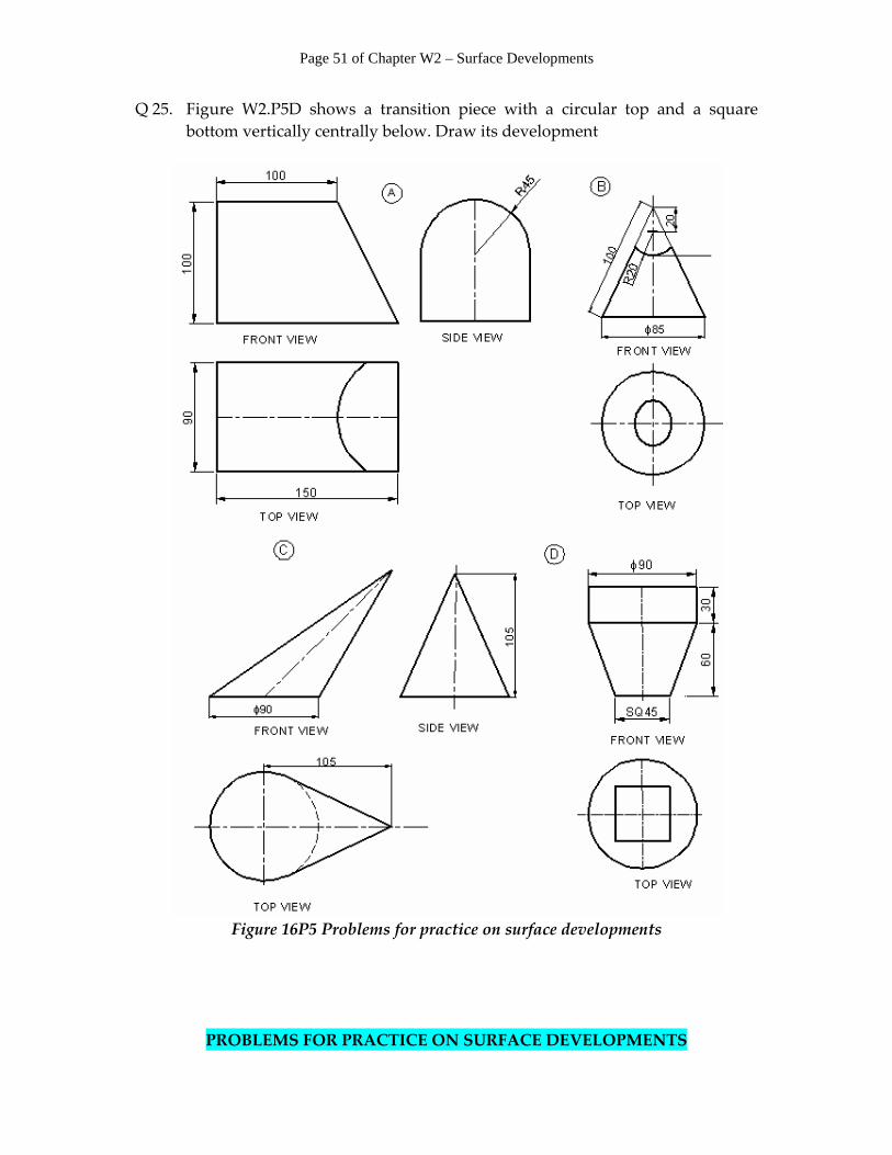
Q 25. Figure W2.P5D shows a transition piece with a circular top and a square bottom vertically centrally below. Draw its development
Figure 16P5 Problems for practice on surface developments
PROBLEMS FOR PRACTICE ON SURFACE DEVELOPMENTS
Page 52 of Chapter W2 – Surface Developments
Q 26. Figure W2.P6A shows a cone with top and faces cut as shown. Draw its
development. Q 27. Figure W2.P6B shows two cones, one over the other centrally above. Draw the
development. Q 28. Figure W2.P6C shows two cylinders, one over the other centrally above. Draw
the development. Q 29. Figure W2.P6D shows a transition piece with a circular top and bottom
eccentrically. Draw its development Q 30. Figure W2.P6E shows a funnel. Draw its development. Q 31. Figure W2.P6F shows a cylinder with a hole of 50‐mm diameter centrally.
Draw its development.

Page 53 of Chapter W2 – Surface Developments
Figure 16P6 Problems for practice on surface developments

Page 54 of Chapter W2 – Surface Developments
PROBLEMS FOR PRACTICE PRISMS Q 32. A triangular prism with bases of lengths equal to 60 mm, 75 mm and 85 mm and a height of 100 mm is to be made. Draw its development, if the top is to be kept open. Q 33. Draw the development of a rectangular prism with base of 120 mm x 80 mm and height of 120 mm. Show the top and bottom also. Q 34. A hut is to be made of thin sheets with width and depth = 200 mm, height in centre = 250 mm, height on sides = 175 mm. An opening of 100‐mm width and 150‐mm height is to be kept in the front side. Draw its development. PYRAMIDS Q 35. Draw the development of a rectangular pyramid with a base of 90 mm x 60 mm and a height of 120 mm. Q 36. A rectangular pyramid with base of 70 mm x 40 mm and a height of 100 mm
is cut by an inclined plane in the longer side passing at the mid‐height at an angle of 30 degrees. Draw its development.
CYLINDERS Q 37. A cylinder with diameter of 130 mm is cut by 2 planes in the centre. Both the
plane make angles of 30 degrees with the vertical at height of 120 mm such that the sides are smaller than the central height. Draw its development.
Q 38. A vertical cylinder with a diameter of 200 mm and a height of 150 mm has to
support another cylinder with a diameter of 150 mm at a height of 100 mm from the base by making a circular cut in the vertical cylinder. Draw the development for the vertical cylinder.
CONES Q 39. A cone with a base of 120 mm and a height of 150 mm is to have a solid horizontal cylinder with a diameter of 30 mm through its centre at its middle. Draw the development of the cone.
Q 40. A funnel is to be made by joining two pieces. Its top and bottom diameters are
100 mm and 20 mm respectively with a vertical height of 80 mm. Its bottom

Page 55 of Chapter W2 – Surface Developments
pipe is tapered from a 20‐mm to a 10‐mm diameter with a length of 100 mm. Draw the development of each part.
Q 41. Draw the development of a right circular cone with a base diameter of 80 mm and a height of 100 mm if it is cut by an inclined plane at a vertical height of 30 mm from the apex.
(a) The angle of the cutting plane is 20 degrees with the horizontal. (b) The angle of the cutting plane is 60 degrees with the horizontal. SPHERES Q 42. A spherical ball with a diameter of 150 mm is to be made by joining 12 arched
elements. Draw the shape of at least three elements. Q 43. A spherical ball with a diameter of 200 mm is to be made by theZone method.
Draw the development for the upper‐half portion only.