Embed Size (px)
Citation preview
MDT TUBE LEAK TEST FOR LARGE PRODUCTION
C. Capoccia, B. Esposito, B. Ponzio, V. Russo, M.C. Spitalieri
Laboratori Nazionali di Frascati
Abstract
A leak detection system, developed for the QA/QC of the MDT tubes during massproduction at LNF, is presented. A prototype of an automated station for three tubes,based on Helium mass spectrometer, has been realized. The preliminary results arereported. The test station for the mass production will have 64 tubes and will performin an integrated way the gas leak rate and the high voltage test. Only the gas leak testis described here.

1
1. Introduction
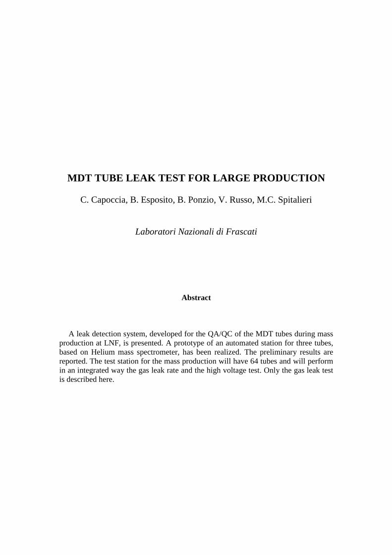
To ensure the mechanical and electrical quali ty of the tubes during production, thefollowing tests for each single tube are foreseen: gas leak rate, wire tension andcurrent leakage. An amount of ≈30000 tubes have to produced and tested at LNF. Asa consequence a computer-controlled system, which minimizes the operator presence,is required. An integrated station for the Quali ty Assurance and Quali ty Control of theMDT tubes during mass production at LNF has been designed to test 64 tubes. Aprototype of an automated station for three tubes has been realized (fig.1-2). Thepreliminary results concerning the leak rate test are reported. The Atlas MDT tubeassembly specifications [1] require a maximum gas leak rate for the single tube of1×10-8 barl/s, with the tube operated at an absolute pressure of 3 bar. A Helium massspectrometer to detect the leak has been used.
2. Leak detection system
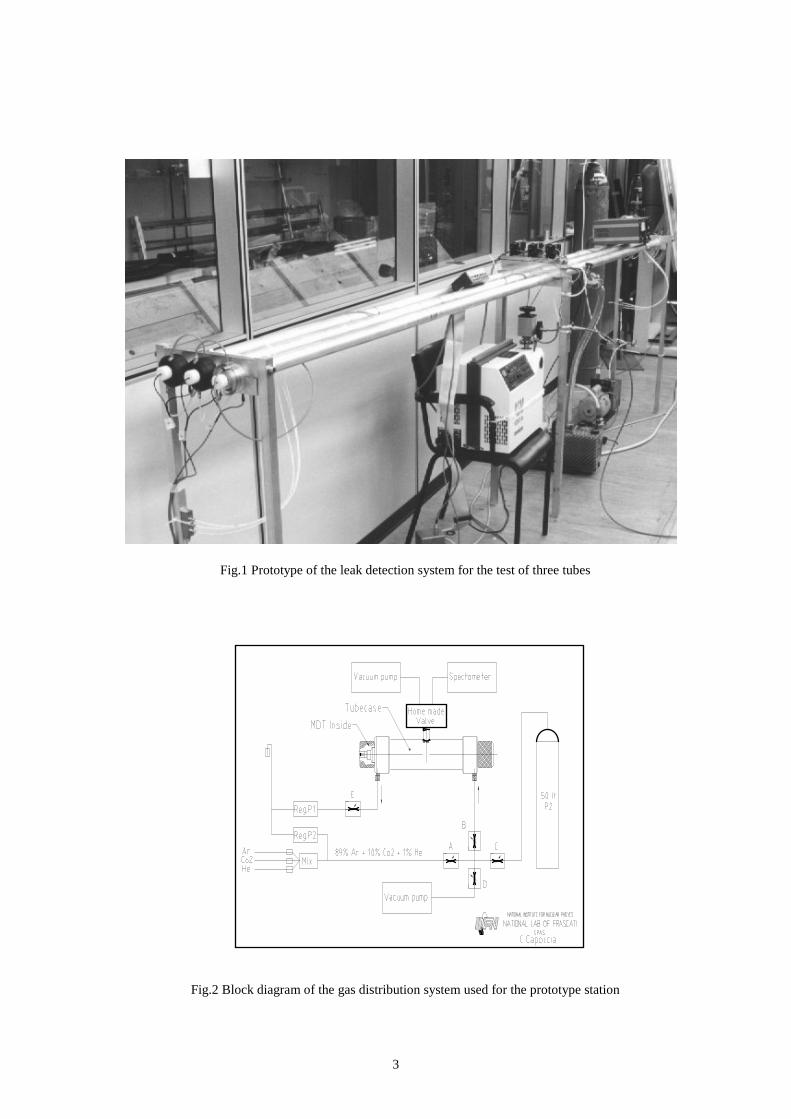
The general scheme of the leak detection system is shown in fig.3. The system hasbeen designed for the parallel test of 64 tubes, in order to follow the tube dailyproduction at LNF. The leak test will be performed on each single tube, analysingwith a mass spectrometer, the He content inside each individual cylindrical tube-casein which the tube is inserted and enclosed by two end-cups.
The main components of the system are:
• Cylindrical tube-cases used to house the tubes to be measured.• A Helium mass spectrometer to detect the gas leak rate.• A vacuum pump to empty the system before the measurement (Turbo-molecular
pump system).• A vacuum pump to empty the MDT tube before the gas filli ng (Dry vacuum
pump).• A valve system to control connection to the pump and to the He spectrometer.
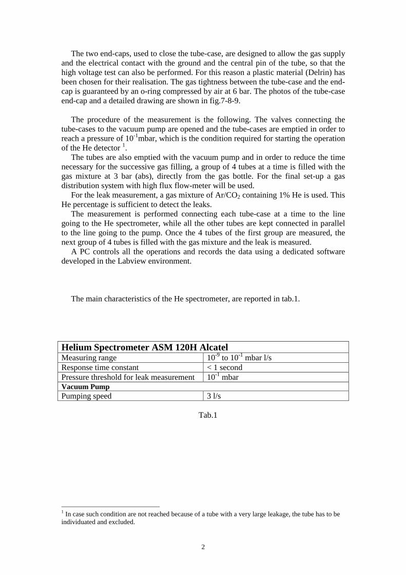
Each tube-case has been realised using a aluminium tube with inner and outerdiameters respectively of 36 and 40 mm. The length of the tube-cases was 4 m inorder to match the length of the tubes to be tested. In fig.1 a photo of the system isshown and fig.2 describes the gas distribution system. A detailed drawing of thesingle tube-case and his connection with the valve system is reported in fig.4.
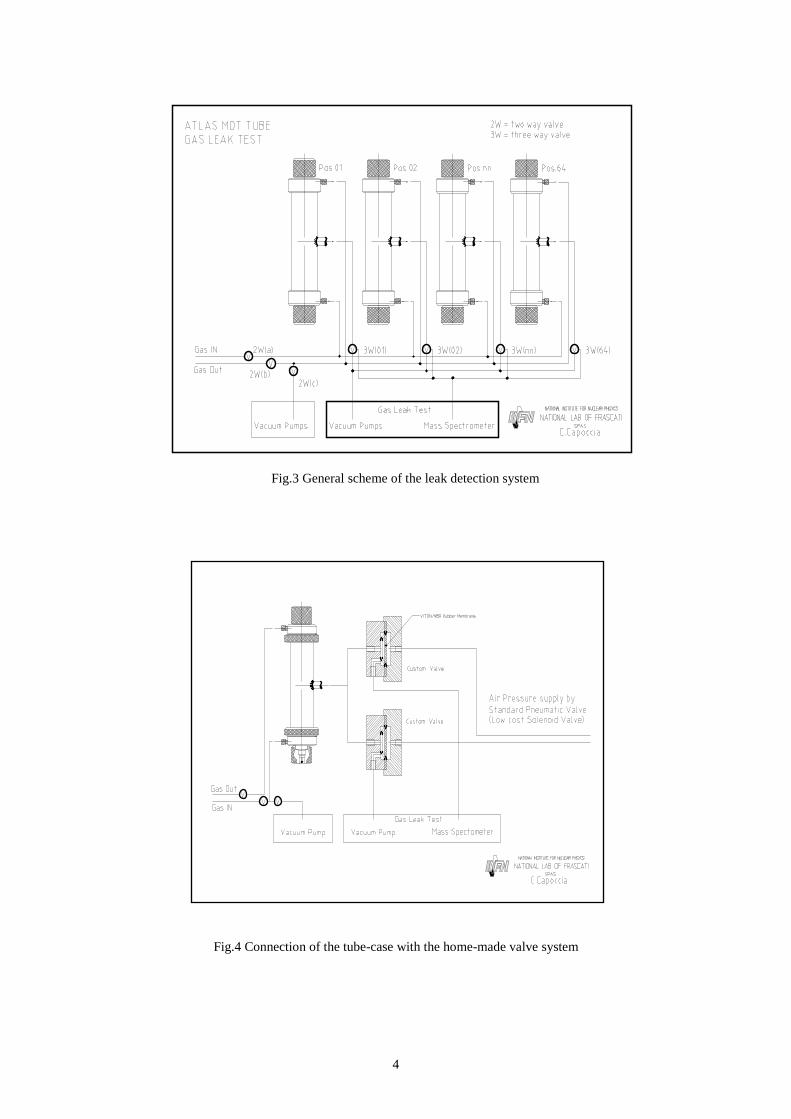
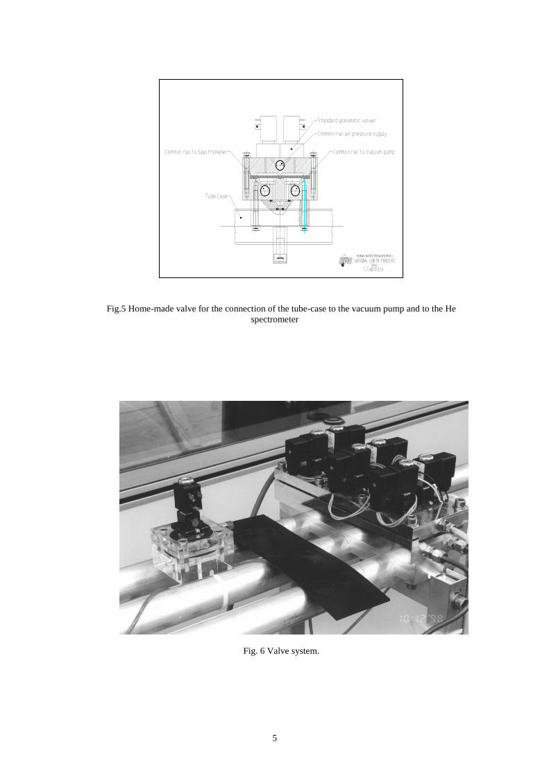
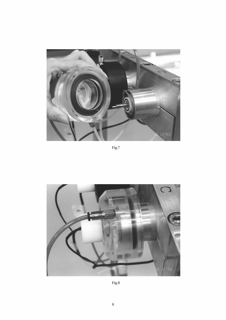
The valve system must have good vacuum characteristics. For cost reasons insteadof commercial vacuum valves, specially designed valves have been used. As shown infig.4, there are two independent valves for each tube-case, one for the connection tothe spectrometer and the other to the vacuum pump. The single valve has beenrealised using a pneumatic valve to control, by means of a neoprene membrane, theopening or closing of the connection. A detailed drawing of the single valve and thevalve system realised for the prototype station are shown in fig.5 and fig.6.
2
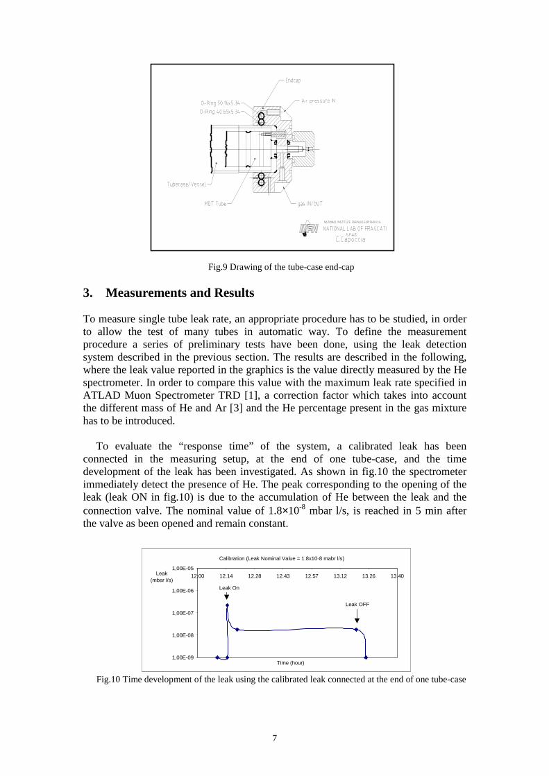
The two end-caps, used to close the tube-case, are designed to allow the gas supplyand the electrical contact with the ground and the central pin of the tube, so that thehigh voltage test can also be performed. For this reason a plastic material (Delrin) hasbeen chosen for their realisation. The gas tightness between the tube-case and the end-cap is guaranteed by an o-ring compressed by air at 6 bar. The photos of the tube-caseend-cap and a detailed drawing are shown in fig.7-8-9.
The procedure of the measurement is the following. The valves connecting thetube-cases to the vacuum pump are opened and the tube-cases are emptied in order toreach a pressure of 10-1mbar, which is the condition required for starting the operationof the He detector 1.
The tubes are also emptied with the vacuum pump and in order to reduce the timenecessary for the successive gas filli ng, a group of 4 tubes at a time is fill ed with thegas mixture at 3 bar (abs), directly from the gas bottle. For the final set-up a gasdistribution system with high flux flow-meter will be used.
For the leak measurement, a gas mixture of Ar/CO2 containing 1% He is used. ThisHe percentage is suff icient to detect the leaks.
The measurement is performed connecting each tube-case at a time to the linegoing to the He spectrometer, while all the other tubes are kept connected in parallelto the line going to the pump. Once the 4 tubes of the first group are measured, thenext group of 4 tubes is fill ed with the gas mixture and the leak is measured.
A PC controls all the operations and records the data using a dedicated softwaredeveloped in the Labview environment.
The main characteristics of the He spectrometer, are reported in tab.1.
Helium Spectrometer ASM 120H AlcatelMeasuring range 10-9 to 10-1 mbar l/sResponse time constant < 1 secondPressure threshold for leak measurement 10-1 mbarVacuum PumpPumping speed 3 l/s
Tab.1
1 In case such condition are not reached because of a tube with a very large leakage, the tube has to beindividuated and excluded.
3
Fig.1 Prototype of the leak detection system for the test of three tubes
Fig.2 Block diagram of the gas distribution system used for the prototype station
4
Fig.3 General scheme of the leak detection system
Fig.4 Connection of the tube-case with the home-made valve system
5
Fig.5 Home-made valve for the connection of the tube-case to the vacuum pump and to the Hespectrometer
Fig. 6 Valve system.
6
Fig.7
Fig.8
7
Fig.9 Drawing of the tube-case end-cap
3. Measurements and Results
To measure single tube leak rate, an appropriate procedure has to be studied, in orderto allow the test of many tubes in automatic way. To define the measurementprocedure a series of preliminary tests have been done, using the leak detectionsystem described in the previous section. The results are described in the following,where the leak value reported in the graphics is the value directly measured by the Hespectrometer. In order to compare this value with the maximum leak rate specified inATLAD Muon Spectrometer TRD [1], a correction factor which takes into accountthe different mass of He and Ar [3] and the He percentage present in the gas mixturehas to be introduced.
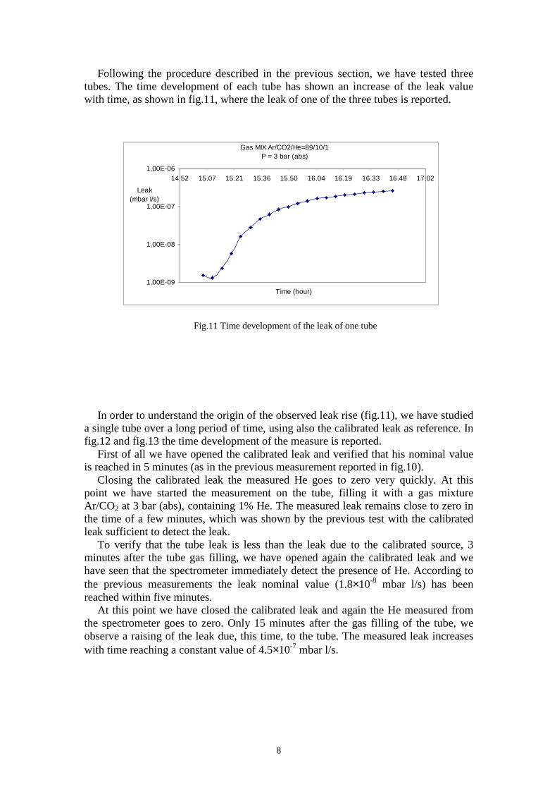
To evaluate the “response time” of the system, a calibrated leak has beenconnected in the measuring setup, at the end of one tube-case, and the timedevelopment of the leak has been investigated. As shown in fig.10 the spectrometerimmediately detect the presence of He. The peak corresponding to the opening of theleak (leak ON in fig.10) is due to the accumulation of He between the leak and theconnection valve. The nominal value of 1.8×10⁻⁸ mbar l/s, is reached in 5 min afterthe valve as been opened and remain constant.
Fig.10 Time development of the leak using the calibrated leak connected at the end of one tube-case
1,00E-09
1,00E-08
1,00E-07
1,00E-06
1,00E-05
12.00 12.14 12.28 12.43 12.57 13.12 13.26 13.40
Leak On
Leak OFF
Leak (mbar l/s)
Time (hour)
Calibration (Leak Nominal Value = 1.8x10⁻⁸ mabr l/s)
8
Following the procedure described in the previous section, we have tested threetubes. The time development of each tube has shown an increase of the leak valuewith time, as shown in fig.11, where the leak of one of the three tubes is reported.
Fig.11 Time development of the leak of one tube
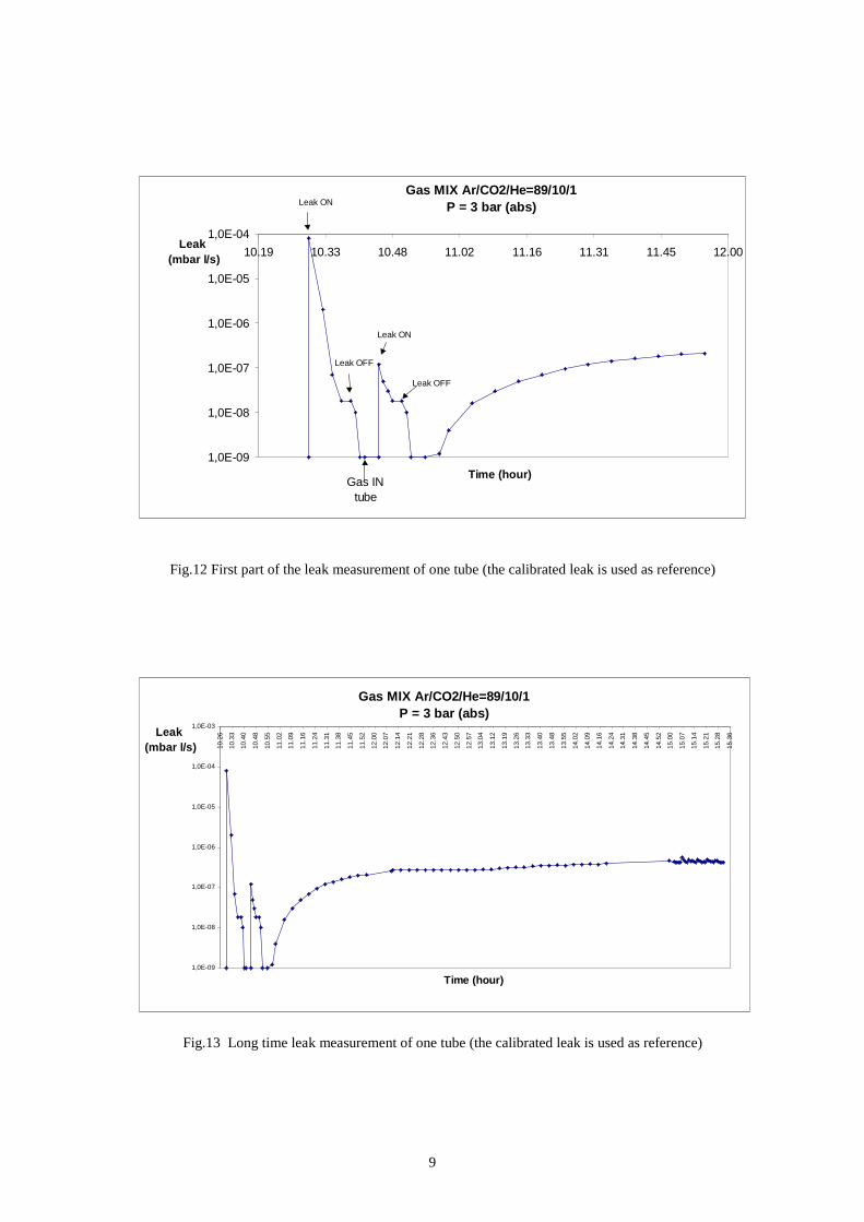
In order to understand the origin of the observed leak rise (fig.11), we have studieda single tube over a long period of time, using also the calibrated leak as reference. Infig.12 and fig.13 the time development of the measure is reported.
First of all we have opened the calibrated leak and verified that his nominal valueis reached in 5 minutes (as in the previous measurement reported in fig.10).
Closing the calibrated leak the measured He goes to zero very quickly. At thispoint we have started the measurement on the tube, filli ng it with a gas mixtureAr/CO2 at 3 bar (abs), containing 1% He. The measured leak remains close to zero inthe time of a few minutes, which was shown by the previous test with the calibratedleak suff icient to detect the leak.
To verify that the tube leak is less than the leak due to the calibrated source, 3minutes after the tube gas filli ng, we have opened again the calibrated leak and wehave seen that the spectrometer immediately detect the presence of He. According tothe previous measurements the leak nominal value (1.8×10⁻⁸ mbar l/s) has beenreached within five minutes.
At this point we have closed the calibrated leak and again the He measured fromthe spectrometer goes to zero. Only 15 minutes after the gas filli ng of the tube, weobserve a raising of the leak due, this time, to the tube. The measured leak increaseswith time reaching a constant value of 4.5×10⁻⁷ mbar l/s.
1,00E-09
1,00E-08
1,00E-07
1,00E-0614.52 15.07 15.21 15.36 15.50 16.04 16.19 16.33 16.48 17.02
Leak (mbar l/s)
Time (hour)
Gas MIX Ar/CO2/He=89/10/1P = 3 bar (abs)
9
Fig.12 First part of the leak measurement of one tube (the calibrated leak is used as reference)
Fig.13 Long time leak measurement of one tube (the calibrated leak is used as reference)
1,0E-09
1,0E-08
1,0E-07
1,0E-06
1,0E-05
1,0E-04
10.19 10.33 10.48 11.02 11.16 11.31 11.45 12.00
Leak ON
Leak ON
Leak OFF
Leak OFF
Gas INtube
Leak (mbar l/s)
Time (hour)
Gas MIX Ar/CO2/He=89/10/1P = 3 bar (abs)
Gas MIX Ar/CO2/He=89/10/1P = 3 bar (abs)
1,0E-09
1,0E-08
1,0E-07
1,0E-06
1,0E-05
1,0E-04
1,0E-03
10.2
6
10.3
3
10.4
0
10.4
8
10.5
5
11.0
2
11.0
9
11.1
6
11.2
4
11.3
1
11.3
8
11.4
5
11.5
2
12.0
0
12.0
7
12.1
4
12.2
1
12.2
8
12.3
6
12.4
3
12.5
0
12.5
7
13.0
4
13.1
2
13.1
9
13.2
6
13.3
3
13.4
0
13.4
8
13.5
5
14.0
2
14.0
9
14.1
6
14.2
4
14.3
1
14.3
8
14.4
5
14.5
2
15.0
0
15.0
7
15.1
4
15.2
1
15.2
8
15.3
6
Time (hour)
Leak (mbar l/s)
10
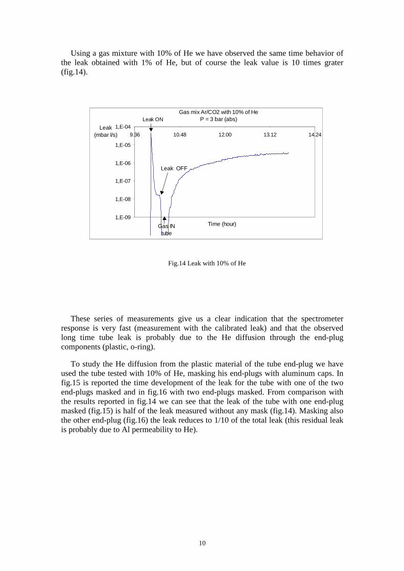
Using a gas mixture with 10% of He we have observed the same time behavior ofthe leak obtained with 1% of He, but of course the leak value is 10 times grater(fig.14).
Fig.14 Leak with 10% of He
These series of measurements give us a clear indication that the spectrometerresponse is very fast (measurement with the calibrated leak) and that the observedlong time tube leak is probably due to the He diffusion through the end-plugcomponents (plastic, o-ring).
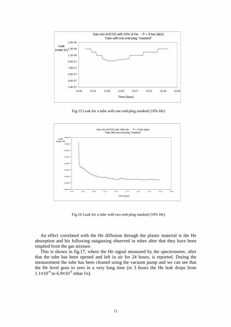
To study the He diffusion from the plastic material of the tube end-plug we haveused the tube tested with 10% of He, masking his end-plugs with aluminum caps. Infig.15 is reported the time development of the leak for the tube with one of the twoend-plugs masked and in fig.16 with two end-plugs masked. From comparison withthe results reported in fig.14 we can see that the leak of the tube with one end-plugmasked (fig.15) is half of the leak measured without any mask (fig.14). Masking alsothe other end-plug (fig.16) the leak reduces to 1/10 of the total leak (this residual leakis probably due to Al permeabili ty to He).
1,E-09
1,E-08
1,E-07
1,E-06
1,E-05
1,E-04
9.36 10.48 12.00 13.12 14.24
Leak ONGas mix Ar/CO2 with 10% of He
P = 3 bar (abs)
Leak OFF
Time (hour)
Leak (mbar l/s)
Gas INtube
11
Fig.15 Leak for a tube with one end-plug masked (10% He)
Fig.16 Leak for a tube with two end-plug masked (10% He)
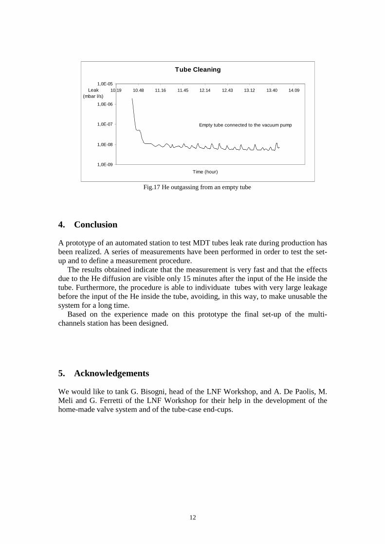
An effect correlated with the He diffusion through the plastic material is the Heabsorption and his following outgassing observed in tubes after that they have beenemptied from the gas mixture.
This is shown in fig.17, where the He signal measured by the spectrometer, afterthat the tube has been opened and left in air for 24 hours, is reported. During themeasurement the tube has been cleaned using the vacuum pump and we can see thatthe He level goes to zero in a very long time (in 3 hours the He leak drops from1.1×10-8 to 6.9×10⁻⁹ mbar l/s).
1,0E-07
3,0E-07
5,0E-07
7,0E-07
9,0E-07
1,1E-06
1,3E-06
1,5E-06
14.09 14.24 14.38 14.52 15.07 15.21 15.36 15.50
Leak (mbar l/s)
Time (hour)
Gas mix Ar/CO2 with 10% of He - P = 3 bar (abs)Tube with one end-plug "masked"
0,000E+00
1,000E-07
2,000E-07
3,000E-07
4,000E-07
5,000E-07
6,000E-07
7,000E-07
8,000E-07
9.50 10.19 10.48 11.16 11.45 12.14 12.43 13.12 13.40 14.09
Time (hour)
Leak (mbar l/s)
Gas mix Ar/CO2 with 10% He - P = 3 bar (abs) Tube with two end-plug "masked"
12
Fig.17 He outgassing from an empty tube
4. Conclusion
A prototype of an automated station to test MDT tubes leak rate during production hasbeen realized. A series of measurements have been performed in order to test the set-up and to define a measurement procedure.
The results obtained indicate that the measurement is very fast and that the effectsdue to the He diffusion are visible only 15 minutes after the input of the He inside thetube. Furthermore, the procedure is able to individuate tubes with very large leakagebefore the input of the He inside the tube, avoiding, in this way, to make unusable thesystem for a long time.
Based on the experience made on this prototype the final set-up of the multi -channels station has been designed.
5. Acknowledgements
We would like to tank G. Bisogni, head of the LNF Workshop, and A. De Paolis, M.Meli and G. Ferretti of the LNF Workshop for their help in the development of thehome-made valve system and of the tube-case end-cups.
Tube Cleaning
1,0E-09
1,0E-08
1,0E-07
1,0E-06
1,0E-05
10.19 10.48 11.16 11.45 12.14 12.43 13.12 13.40 14.09Leak (mbar l/s)
Time (hour)
Empty tube connected to the vacuum pump
13
6. References
[1] ATLAS Collaboration, ATLAS Muon Spectrometer Technical Design Report,CERN/LHC/97- 22 ATLAS TDR 10
[2] A.Balla et al., MDT Wire Tension Measurement using an electrostatic method,ATLAS MUON Note NO-98-264
[3] V.T.Braic et al., Leak Detection System for Mass productin of DT Detectors,ATLAS MUON Note NO-98-225