Embed Size (px)
Citation preview

MDT technologies GmbH • 51766 Engelskirchen • Papiermühle 1 Tel.: +49-2263-880 • Fax: +49-2263-4588 • [email protected] • www.mdt.de
1/2014
Technical Manual
MDT Weather station
SCN-WS3HW.01
Technisches Manual Weather station SCN‐WS3HW.01
MDT technologies GmbH • 51766 Engelskirchen • Papiermühle 1 Tel.: +49-2263-880 • Fax: +49-2263-4588 • [email protected] • www.mdt.de
2
1 Content 1 Content ................................................................................................................................................. 2
2 Overview ............................................................................................................................................... 3
2.1 Overview ........................................................................................................................................ 3
2.2. Usage & Areas of use .................................................................................................................... 3
2.3 Exemplary circuit diagram ............................................................................................................. 4
2.4 Sezup & Installation instructure .................................................................................................... 4
2.5 Functions ....................................................................................................................................... 5
2.5.1 Overview functions ................................................................................................................. 6
2.6 Settings at the ETS‐Software ......................................................................................................... 7
2.7 Starting Up ..................................................................................................................................... 7
3 Communication objects ........................................................................................................................ 8
3.1 Overview ........................................................................................................................................ 8
3.2 Default settings of the communication objects ............................................................................ 9
4 Reference ETS‐Parameter .................................................................................................................. 10
4.1 General ........................................................................................................................................ 10
4.2 Brightness sensors ....................................................................................................................... 12
4.2.1 Treshold value .......................................................................................................................... 14
4.2.2 Facade control ...................................................................................................................... 18
Data type and moving function ................................................................................................. 20
Teach‐In Funktion ...................................................................................................................... 23
Temperature‐/Blockfunction ..................................................................................................... 24
4.3 Dusk sensor ................................................................................................................................. 26
4.4 Wind sensor ................................................................................................................................. 28
4.5 Temperature sensor .................................................................................................................... 30
5 Index ................................................................................................................................................... 33
5.1 List of illustrations ....................................................................................................................... 33
5.2 List of tables................................................................................................................................. 34
6.1 Statutory requirements ............................................................................................................... 35
6.2 Routine disposal .......................................................................................................................... 35
6.3 Assemblage .................................................................................................................................. 35
6.4 Datasheet .................................................................................................................................... 36
Technisches Manual Weather station SCN‐WS3HW.01
MDT technologies GmbH • 51766 Engelskirchen • Papiermühle 1 Tel.: +49-2263-880 • Fax: +49-2263-4588 • [email protected] • www.mdt.de
3
2Overview
2.1Overview The manual refers to the following device (Order Code respectively printed in bold type):
SCN‐WS3HW.01 Weather station Home for outdoor instatllation, IP o Sun protection up to 3 facsades with extensive fassad controlling; Brigthness values
for East, South, West and twilight; Detection of the wind speed and the temperature; Power supply via bus
The following additional devices for weather detection are located in our assortment at the moment and complete the package for complete weather detection.
SCN‐RS1R1.01 Rain sensor
SCN‐SS1H.01 Sun sensor for the indoor inastallation on windwows with vacuum cup
2.2.Usage&Areasofuse The MDT Weather station Home is made for the weather detection for private use. The installation is made in the outdoor area and should be made on a pole. Alternative, the weather station can be installed on a wall at the southern side. The connection to the bus is made via a 5m long bus cable, which is included in the delivery contents. Three brightness sensors are included in the weather station, which are faced to the sky directions East, West and South (Have a look at the mounting direction – south). These can be controlled via two threshold values and an extensive facade controlling unit for shutter and blinds. Additional a twilight sensor is integrated. Via an individually adjustable wind sensor, the wind speed can be captured and actions can be performed. The temperature sensor, which can be adjusted with threshold values, complete the service portfolio of the weather station.
Technisches Manual Weather station SCN‐WS3HW.01
MDT technologies GmbH • 51766 Engelskirchen • Papiermühle 1 Tel.: +49-2263-880 • Fax: +49-2263-4588 • [email protected] • www.mdt.de
4
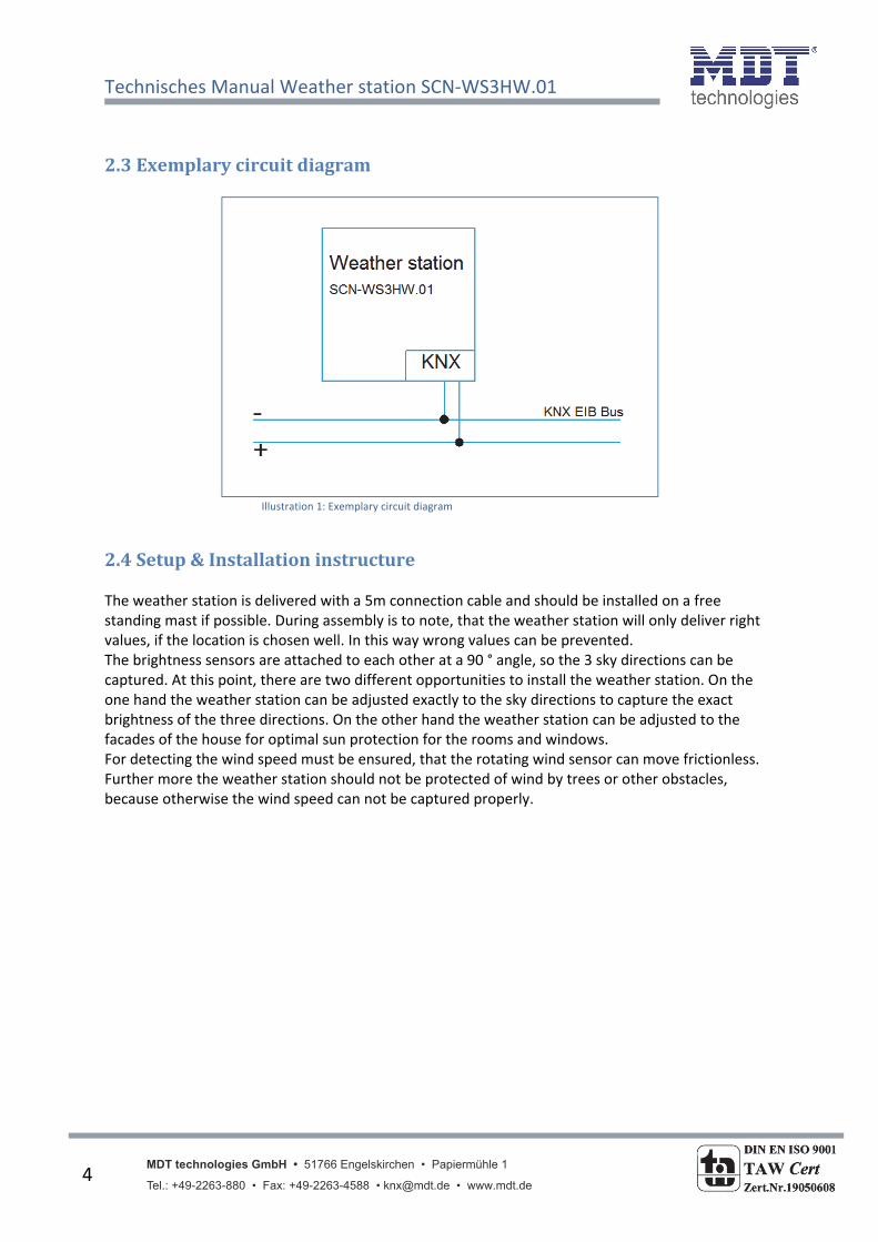
2.3Exemplarycircuitdiagram
Illustration 1: Exemplary circuit diagram
2.4Setup&Installationinstructure The weather station is delivered with a 5m connection cable and should be installed on a free standing mast if possible. During assembly is to note, that the weather station will only deliver right values, if the location is chosen well. In this way wrong values can be prevented. The brightness sensors are attached to each other at a 90 ° angle, so the 3 sky directions can be captured. At this point, there are two different opportunities to install the weather station. On the one hand the weather station can be adjusted exactly to the sky directions to capture the exact brightness of the three directions. On the other hand the weather station can be adjusted to the facades of the house for optimal sun protection for the rooms and windows. For detecting the wind speed must be ensured, that the rotating wind sensor can move frictionless. Further more the weather station should not be protected of wind by trees or other obstacles, because otherwise the wind speed can not be captured properly.
Technisches Manual Weather station SCN‐WS3HW.01
MDT technologies GmbH • 51766 Engelskirchen • Papiermühle 1 Tel.: +49-2263-880 • Fax: +49-2263-4588 • [email protected] • www.mdt.de
5
2.5Functions The functions of the weather station are divided into general settings and the 6 sensors. Every sensor must be activated at the general settings for further parameterization. The following submenus can be shown and parameterized further:
General setting The general settings are alsways visible. Changes, which are done at this submenu, are valid for the whole device. The single sensors can be activated or deactivated at this submenu.
Brightness sensor east The brightness sensor for the east direction can be parameterized at this submenu. Two thresholds can be activated and parameterized further. Further more an extensive façade control is available as soon as at least one threshold is active.
Brightness sensor south The brightness sensor for the south direction with the same functions as described above can be parameterized at this submenu.
Brightness sensor west The brightness sensor for the west direction with the same functions as described above can be parameterized at this submenu.
Dusk sensor The dusk sensor is calculated from the maximum of the three brightness sensors. The calculated dusk value can be sent and a day/night recognization can be activated.
Wind sensor The wind sensor can capture the current wind speed and cause actions according to adjusted tresholds. So alarms, e.g. for shutter actuators, can be created.
Temperature sensor The temperature sensor can be parameterized with up to two tresholds and send telegrams according to the adjusted thresholds.

Technisches Manual Weather station SCN‐WS3HW.01
MDT technologies GmbH • 51766 Engelskirchen • Papiermühle 1 Tel.: +49-2263-880 • Fax: +49-2263-4588 • [email protected] • www.mdt.de
6
2.5.1OverviewfunctionsGeneral settings general Startup time
Limitation of telegrams
cyclic operating acknowledge
Behavior after programming
Brightness sensor East active/not active
Brightness sensor South active/not active
Brightness sensor West active/not active
Dusk sensor active/not active
Wind sensor active/not active
Temperature sensor active/not active
Brightness sensor East/South/West
general Sending condition
Threshold 1 und 2 activatable
Facade control activatable
Threshold 1 Thresholds adjustable
Detection time adjsutable
Behavior at going below/above limits adjustable
Cyclic sending
Blocking object
Threshold adjustment via object
Treshold 2 Thresholds adjustable
Detection time adjsutable
Behavior at going below/above limits adjustable
Cyclic sending
Blocking object
Facade control Data object for moving adjustable
Reaction to treshold 1
Reaction to treshold 2
Cyclic sending
Blocking object
Option with temperature influence
Dusk sensor allgemein Sending condition
Day/Night object
Wind sensor allgemein Sending condition
Schwellwert Limits adjustable
Detection time adjustable
Reaction to treshold
Cyclic sending
Temperature sensor allgemein Sending condition
Schwellwert 1 und 2 Temperature values adjustable
Behavior at going below/above limits adjustable
Cyclic sending Chart 1: Overview functions
Technisches Manual Weather station SCN‐WS3HW.01
MDT technologies GmbH • 51766 Engelskirchen • Papiermühle 1 Tel.: +49-2263-880 • Fax: +49-2263-4588 • [email protected] • www.mdt.de
7
2.6SettingsattheETS‐Software Selection at the product database: Manufacturer: MDT Technologies Product family: Actuators Product type: Weather detection Medium Type: Twisted Pair (TP) Product name: addicted to the used type, e.g.: SCN‐WS3HW.01 Wetterstation Home Order number: addicted to the used type, e.g.: SCN‐WS3HW.01
2.7StartingUp After wiring the allocation of the physical address and the parameterization of every channel follow:
(1) Connect the interface with the bus, e.g. MDT USB interface (2) set bus power up (3) Activate the programming mode by closing the reed contact with the provided magnet
red programming LED lights (4) Loading of the physical address out of the ETS‐Software by using the interface(red LED goes
out, as well this process was completed successful) (5) Loading of the application, with requested parameterization (6) Switch the power supply on (7) If the device is enabled you can test the requested functions(also possible by using the ETS‐
Software)
Technisches Manual Weather station SCN‐WS3HW.01
MDT technologies GmbH • 51766 Engelskirchen • Papiermühle 1 Tel.: +49-2263-880 • Fax: +49-2263-4588 • [email protected] • www.mdt.de
8
3Communicationobjects
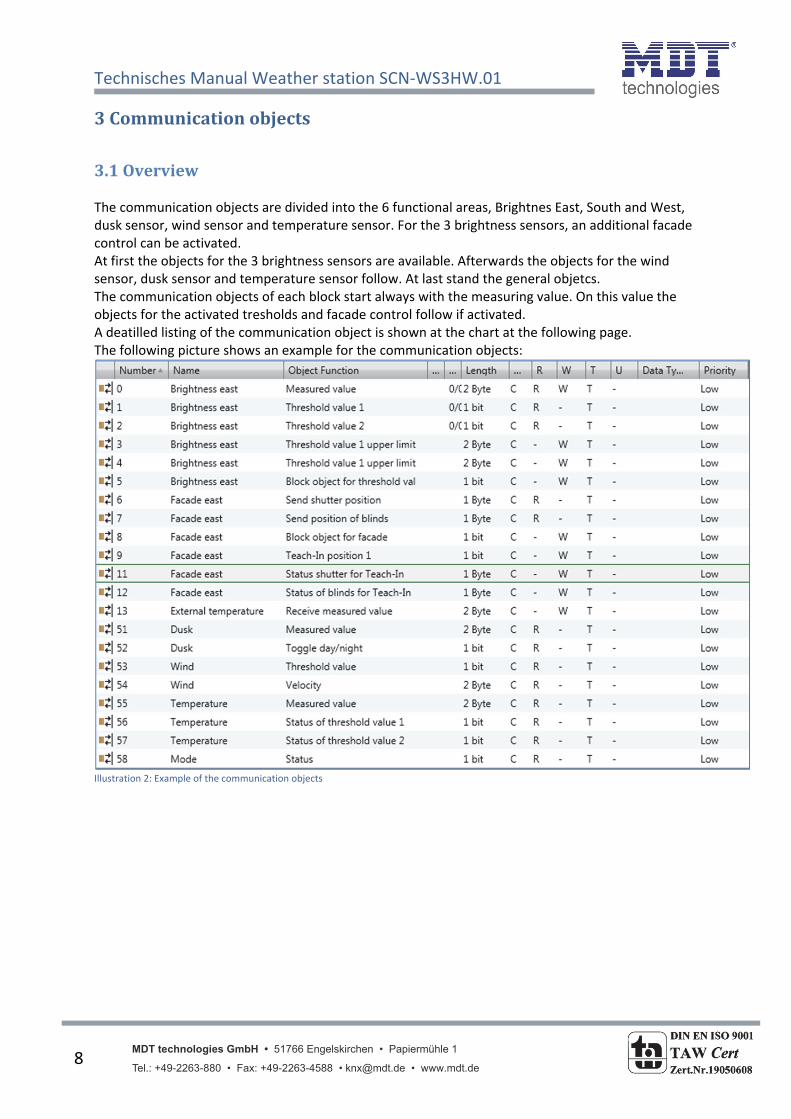
3.1Overview The communication objects are divided into the 6 functional areas, Brightnes East, South and West, dusk sensor, wind sensor and temperature sensor. For the 3 brightness sensors, an additional facade control can be activated. At first the objects for the 3 brightness sensors are available. Afterwards the objects for the wind sensor, dusk sensor and temperature sensor follow. At last stand the general objetcs. The communication objects of each block start always with the measuring value. On this value the objects for the activated tresholds and facade control follow if activated. A deatilled listing of the communication object is shown at the chart at the following page. The following picture shows an example for the communication objects:
Illustration 2: Example of the communication objects

Technisches Manual Weather station SCN‐WS3HW.01
MDT technologies GmbH • 51766 Engelskirchen • Papiermühle 1 Tel.: +49-2263-880 • Fax: +49-2263-4588 • [email protected] • www.mdt.de
9
3.2DefaultsettingsofthecommunicationobjectsThe following chart shows the default settings of the communication objects:
Default setttingsNr. Channel/Input Function Length Priority C R W T U
0 Brightness East Measured value 2 Byte Low X X X X
1 Brightness East Treshold value 1 1 Bit Low X X X
2 Brightness East Treshold value 2 1 Bit Low X X X
3 Brightness East Treshold value 1 upper limit 1 Bit Low X X X
4 Brightness East Treshold value 1 lower limit 1 Bit Low X X X
5 Brightness East Block object for threshold value
1 Bit Low X X X
6 Facade East Send position of blinds 1 Byte Low X X X
6 Facade East Scene 1 Byte Low X X X
6 Facade East Send shutter position 1 Byte Low X X X
7 Facade East Send position of slats 1 Byte Low X X X
8 Facade East Block object for facade 1 Bit Low X X X
9 Facade East Teach‐In position 1 1 Bit Low X X X
10 Facade East Teach‐In position 2 1 Bit Low X X X
11 Facade East Status blinds for Teach‐In 1 Byte Low X X X
11 Facade East Status shutter for Teach‐In 1 Byte Low X X X
12 Facade East Status slats for Teach‐In 1 Byte Low X X X
13 Facade East Receive measured value 2 Byte Low X X X
+17 Brightness South/Facade South
+34 Brightness West/Facade West
51 Dusk Measured value 2 Byte Low X X X
52 Dusk Toogle day/night 1 Bit Low X X X
53 Wind Treshold value 1 Bit Low X X X
54 Wind Velocity 2 Byte Low X X X
55 Temperature Measured value 2 Byte Low X X X
56 Temperature Status of threshold value 1 1 Bit Low X X X
57 Temperature Status of threshold value 2 1 Bit Low X X X
58 Mode Status 1 Bit Low X X X
59 Dusk Shutter move up/down 1 Bit Low X X X
60 Dusk Block object shutter up/dwn 1 Bit Low X X XChart 2: Default settings of the communication objects
You can see the default values for the communication objects from the upper chart. According to
requirements the priority of the particular communication objects as well as the flags can be
adjusted by the user. The flags allocates the function of the objects in the programming thereby
stands C for communication, R for Read, W for write, T for transmit and U for update.
Technisches Manual Weather station SCN‐WS3HW.01
MDT technologies GmbH • 51766 Engelskirchen • Papiermühle 1 Tel.: +49-2263-880 • Fax: +49-2263-4588 • [email protected] • www.mdt.de
10
4ReferenceETS‐Parameter
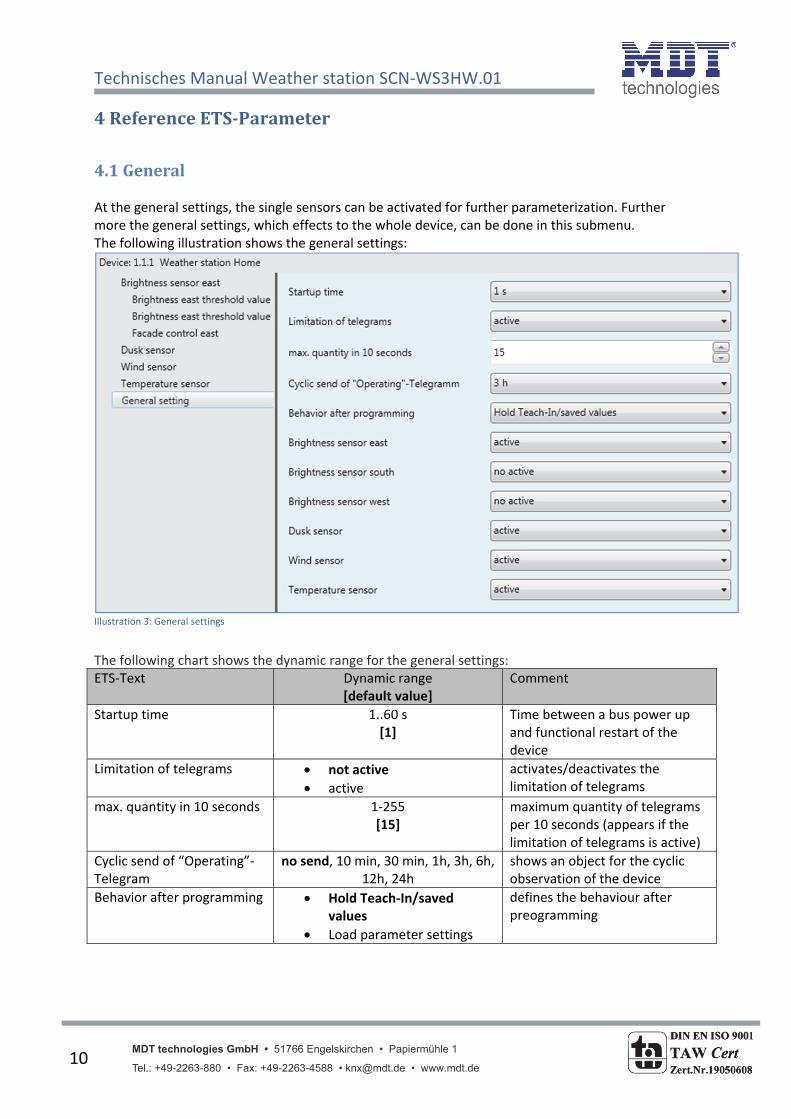
4.1General At the general settings, the single sensors can be activated for further parameterization. Further more the general settings, which effects to the whole device, can be done in this submenu. The following illustration shows the general settings:
Illustration 3: General settings
The following chart shows the dynamic range for the general settings: ETS‐Text Dynamic range
[default value] Comment
Startup time 1..60 s [1]
Time between a bus power up and functional restart of the device
Limitation of telegrams not active
active
activates/deactivates the limitation of telegrams
max. quantity in 10 seconds 1‐255 [15]
maximum quantity of telegrams per 10 seconds (appears if the limitation of telegrams is active)
Cyclic send of “Operating”‐Telegram
no send, 10 min, 30 min, 1h, 3h, 6h, 12h, 24h
shows an object for the cyclic observation of the device
Behavior after programming Hold Teach‐In/saved values
Load parameter settings
defines the behaviour after preogramming
Technisches Manual Weather station SCN‐WS3HW.01
MDT technologies GmbH • 51766 Engelskirchen • Papiermühle 1 Tel.: +49-2263-880 • Fax: +49-2263-4588 • [email protected] • www.mdt.de
11
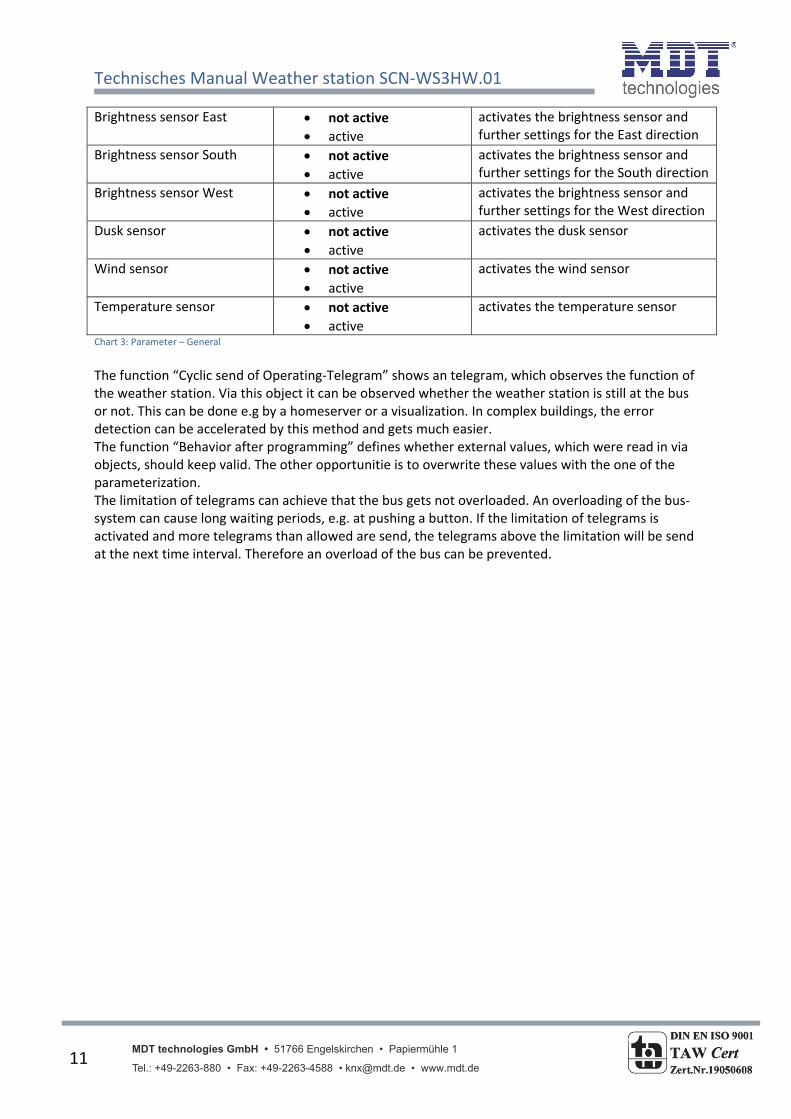
Brightness sensor East not active
active
activates the brightness sensor and further settings for the East direction
Brightness sensor South not active
active
activates the brightness sensor and further settings for the South direction
Brightness sensor West not active
active
activates the brightness sensor and further settings for the West direction
Dusk sensor not active
active
activates the dusk sensor
Wind sensor not active
active
activates the wind sensor
Temperature sensor not active
active
activates the temperature sensor
Chart 3: Parameter – General
The function “Cyclic send of Operating‐Telegram” shows an telegram, which observes the function of the weather station. Via this object it can be observed whether the weather station is still at the bus or not. This can be done e.g by a homeserver or a visualization. In complex buildings, the error detection can be accelerated by this method and gets much easier. The function “Behavior after programming” defines whether external values, which were read in via objects, should keep valid. The other opportunitie is to overwrite these values with the one of the parameterization. The limitation of telegrams can achieve that the bus gets not overloaded. An overloading of the bus‐system can cause long waiting periods, e.g. at pushing a button. If the limitation of telegrams is activated and more telegrams than allowed are send, the telegrams above the limitation will be send at the next time interval. Therefore an overload of the bus can be prevented.
Technisches Manual Weather station SCN‐WS3HW.01
MDT technologies GmbH • 51766 Engelskirchen • Papiermühle 1 Tel.: +49-2263-880 • Fax: +49-2263-4588 • [email protected] • www.mdt.de
12
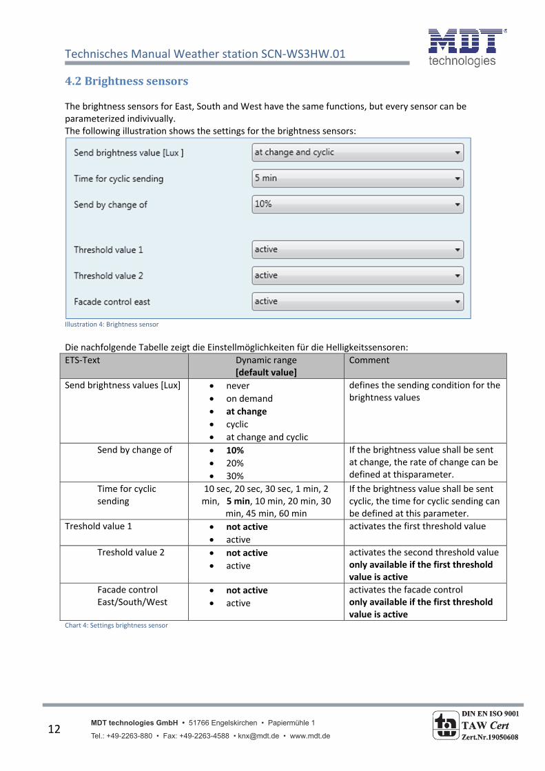
4.2Brightnesssensors The brightness sensors for East, South and West have the same functions, but every sensor can be parameterized indivivually. The following illustration shows the settings for the brightness sensors:
Illustration 4: Brightness sensor
Die nachfolgende Tabelle zeigt die Einstellmöglichkeiten für die Helligkeitssensoren:
ETS‐Text Dynamic range [default value]
Comment
Send brightness values [Lux] never
on demand
at change
cyclic
at change and cyclic
defines the sending condition for the brightness values
Send by change of 10%
20%
30%
If the brightness value shall be sent at change, the rate of change can be defined at thisparameter.
Time for cyclic sending
10 sec, 20 sec, 30 sec, 1 min, 2 min, 5 min, 10 min, 20 min, 30
min, 45 min, 60 min
If the brightness value shall be sent cyclic, the time for cyclic sending can be defined at this parameter.
Treshold value 1 not active
active
activates the first threshold value
Treshold value 2 not active
active
activates the second threshold value only available if the first threshold value is active
Facade control East/South/West
not active
active
activates the facade control only available if the first threshold value is active
Chart 4: Settings brightness sensor

Technisches Manual Weather station SCN‐WS3HW.01
MDT technologies GmbH • 51766 Engelskirchen • Papiermühle 1 Tel.: +49-2263-880 • Fax: +49-2263-4588 • [email protected] • www.mdt.de
13
The brightness sensors have their area of application at the control of clouding units and the facade control. Therefore two tresholds can be parameterized and a faceade control can be activated. For activating the second threshold and the facade control, the first threshold must be activated. For parameterizing the brightness values, it is useful to know some popular brightness values. These are shown at the cart below. Attention should be paid to that the measured values depend to the place of installation:
Surfaces illuminated by Approximated illuminance
Bright day of sun 100.000 lx
Clouded summer day 20.000 lx
In the shadow at a summer day 10.000 lx
Clouded winter day 3.500 lx
Office/Room building lights 500 lx
Overhead lightning 100 lx
Street lightning 10 lx
Full moon night 0,25 lx
Starlit night (new moon) 0,001 lx
Clouded night without moon and other extraneous lights
0,00013 lx
Chart 5: Intensity of illumination
The following chart shows the relevant communication objects for the brightness sensors:
Number Name Function Length Usage0 Brightness East Measured value 2 Byte Display of the measured value
17 Brightness South Measured value 2 Byte Display of the measured value
34 Brightness West Measured value 2 Byte Display of the measured value Chart 6: Communication objects brightness sensor
Technisches Manual Weather station SCN‐WS3HW.01
MDT technologies GmbH • 51766 Engelskirchen • Papiermühle 1 Tel.: +49-2263-880 • Fax: +49-2263-4588 • [email protected] • www.mdt.de
14
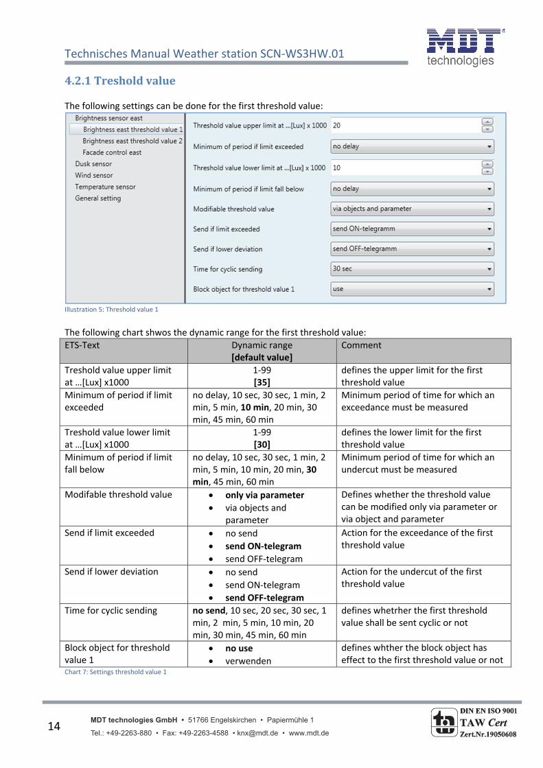
4.2.1Tresholdvalue The following settings can be done for the first threshold value:
Illustration 5: Threshold value 1
The following chart shwos the dynamic range for the first threshold value:
ETS‐Text Dynamic range [default value]
Comment
Treshold value upper limit at …[Lux] x1000
1‐99 [35]
defines the upper limit for the first threshold value
Minimum of period if limit exceeded
no delay, 10 sec, 30 sec, 1 min, 2 min, 5 min, 10 min, 20 min, 30 min, 45 min, 60 min
Minimum period of time for which an exceedance must be measured
Treshold value lower limit at …[Lux] x1000
1‐99 [30]
defines the lower limit for the first threshold value
Minimum of period if limit fall below
no delay, 10 sec, 30 sec, 1 min, 2 min, 5 min, 10 min, 20 min, 30 min, 45 min, 60 min
Minimum period of time for which an undercut must be measured
Modifable threshold value only via parameter
via objects and parameter
Defines whether the threshold value can be modified only via parameter or via object and parameter
Send if limit exceeded no send
send ON‐telegram
send OFF‐telegram
Action for the exceedance of the first threshold value
Send if lower deviation no send
send ON‐telegram
send OFF‐telegram
Action for the undercut of the first threshold value
Time for cyclic sending no send, 10 sec, 20 sec, 30 sec, 1 min, 2 min, 5 min, 10 min, 20 min, 30 min, 45 min, 60 min
defines whetrher the first threshold value shall be sent cyclic or not
Block object for threshold value 1
no use
verwenden
defines whther the block object has effect to the first threshold value or not
Chart 7: Settings threshold value 1

Technisches Manual Weather station SCN‐WS3HW.01
MDT technologies GmbH • 51766 Engelskirchen • Papiermühle 1 Tel.: +49-2263-880 • Fax: +49-2263-4588 • [email protected] • www.mdt.de
15
The following settings can be done for the second threshold value:
Illustration 6: Threshold value 2
The following chart shows the dynamic range for the second threshold value:
ETS‐Text Dynamic range [default value]
Comment
Treshold value upper limit at …[Lux] x1000
1‐99 [40]
defines the upper limit for the second threshold value
Minimum of period if limit exceeded
no delay, 10 sec, 30 sec, 1 min, 2 min, 5 min, 10 min, 20 min, 30 min, 45 min, 60 min
Minimum period of time for which an exceedance must be measured
Treshold value lower limit at …[Lux] x1000
1‐99 [35]
defines the lower limit for the second threshold value
Minimum of period if limit fall below
no delay, 10 sec, 30 sec, 1 min, 2 min, 5 min, 10 min, 20 min, 30 min, 45 min, 60 min
Minimum period of time for which an undercut must be measured
Send if limit exceeded no send
send ON‐telegram
send OFF‐telegram
Action for the exceedance of the second treshold
Send if lower deviation no send
send ON‐telegram
send OFF‐telegram
Action for the undercut of the second threshold value
Time for cyclic sending no send, 10 sec, 20 sec, 30 sec, 1 min, 2 min, 5 min, 10 min, 20 min, 30 min, 45 min, 60 min
defines whetrher the second threshold value shall be sent cyclic or not
Block object for threshold value 2
no use
verwenden
defines whther the block object has effect to the second threshold value or not
Chart 8: Settings threshold value 2

Technisches Manual Weather station SCN‐WS3HW.01
MDT technologies GmbH • 51766 Engelskirchen • Papiermühle 1 Tel.: +49-2263-880 • Fax: +49-2263-4588 • [email protected] • www.mdt.de
16
Attention should be paid to, that a stepping of the threshold value is necessary. That means that the limits of the threshold value 2 must be higher than the ones of the threshold value 1. The following chart shows the stepping of the threshold values 1 and 2:
Illustration7: Stepping of the threshold values 1 & 2
It is also possible to program a crossover of the both threshold values insofar as the upper limt of threshold value 2 is higher than the one of threshold value 1 and the lower limit of threshold value 2 is higher than the one of threshold value 1:
Illustration 8: Overstepping of the threshold values 1&2

Technisches Manual Weather station SCN‐WS3HW.01
MDT technologies GmbH • 51766 Engelskirchen • Papiermühle 1 Tel.: +49-2263-880 • Fax: +49-2263-4588 • [email protected] • www.mdt.de
17
As well for the understepping as for the exceedance of the threshold values a delay can be parameterize. This delay indicates how long the measured brightness value must exceed or underrun the adjusted threshold value. In order that a short darkening, e.g. caused by the passing of clouds, causes a permanent driving of the blinds/shutter, a sufficiently long value should be adjusted here. So the treshold value 1 or 2 is only active if an exceedance or an undercut is measured for the adjusted period of time. Via the corresponding communication object, every threshold value can send its current state. So you get a steady feedback if the trshold value is active or not. The polarity and the sending behaviour of this object can be parameterized individually. There is a common block object available for both threshold values. In the submenu for each threshold value can be defined whether the block object should be used for this threshold value or not. If the object is in us e for this threshold, the threshold value will be blocked with a logical “1”. The unblocking process can be done with a logical “0”. Additional the threshold value can be modified via an object. If the function “Modifable threshold value” is adjusted as “via objects”, two additional obejcts will appear, one for the upper limit and one for the lower limit of the threshold value. Via theses both objects a new value can be assigned to the the first threshold value. The chart shows the relevant communication objects for the threshold values:
Number Name Function Length Usage1 Brightness East Treshold value 1 1 Bit indicates if threshold value1 is active
2 Brightness East Treshold value 2 1 Bit indicates if threshold value2 is active
3 Brightness East Treshold value 1 upper limit
2 Byte Writing a new upper limit for threshold value 1
4 Brightness East Treshold value 1 lower limit
2 Byte Writing a new lower limit for threshold value 1
5 Brightness East Block object for threshold value
1 Bit Blocking the threshold values
18 Brightness South Treshold value 1 1 Bit indicates if threshold value1 is active
19 Brightness South Treshold value 2 1 Bit indicates if threshold value2 is active
20 Brightness South Treshold value 1 upper limit
2 Byte Writing a new upper limit for threshold value 1
21 Brightness South Treshold value 1 lower limit
2 Byte Writing a new lower limit for threshold value 1
21 Brightness South Block object for threshold value
1 Bit Blocking the threshold values
35 Brightness West Treshold value 1 1 Bit indicates if threshold value1 is active
36 Brightness West Treshold value 2 1 Bit indicates if threshold value2 is active
37 Brightness West Treshold value 1 upper limit
2 Byte Writing a new upper limit for threshold value 1
38 Brightness West Treshold value 1 lower limit
2 Byte Writing a new lower limit for threshold value 1
39 Brightness West Block object for threshold value
1 Bit Blocking the threshold values
Chart 9: Communication objekts threshold values
Technisches Manual Weather station SCN‐WS3HW.01
MDT technologies GmbH • 51766 Engelskirchen • Papiermühle 1 Tel.: +49-2263-880 • Fax: +49-2263-4588 • [email protected] • www.mdt.de
18
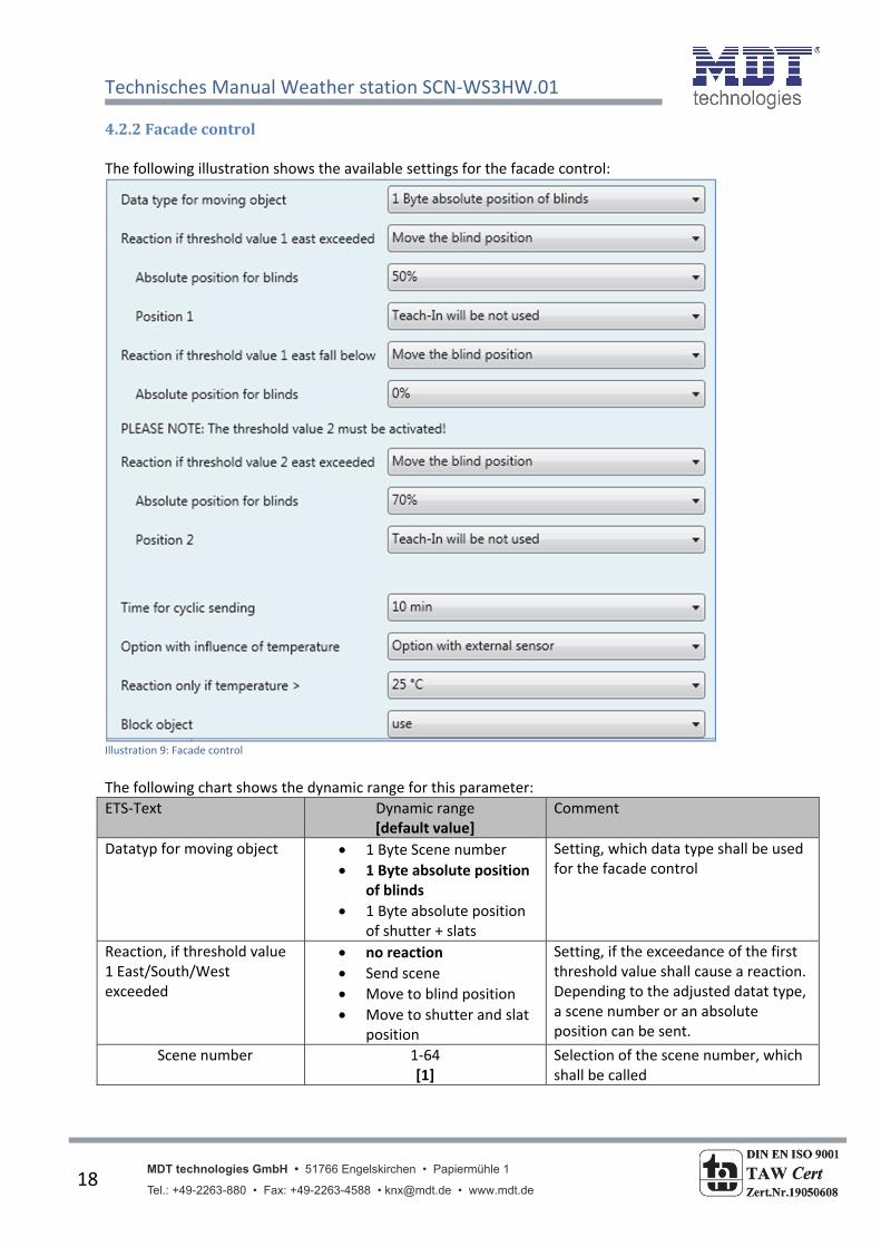
4.2.2Facadecontrol The following illustration shows the available settings for the facade control:
Illustration 9: Facade control
The following chart shows the dynamic range for this parameter:
ETS‐Text Dynamic range [default value]
Comment
Datatyp for moving object 1 Byte Scene number
1 Byte absolute position of blinds
1 Byte absolute position of shutter + slats
Setting, which data type shall be used for the facade control
Reaction, if threshold value 1 East/South/West exceeded
no reaction
Send scene
Move to blind position
Move to shutter and slat position
Setting, if the exceedance of the first threshold value shall cause a reaction. Depending to the adjusted datat type, a scene number or an absolute position can be sent.
Scene number 1‐64 [1]
Selection of the scene number, which shall be called
Technisches Manual Weather station SCN‐WS3HW.01
MDT technologies GmbH • 51766 Engelskirchen • Papiermühle 1 Tel.: +49-2263-880 • Fax: +49-2263-4588 • [email protected] • www.mdt.de
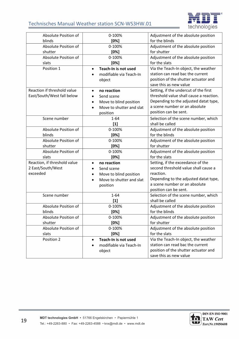
19
Absolute Position of blinds
0‐100% [0%]
Adjustment of the absolute position for the blinds
Absolute Position of shutter
0‐100% [0%]
Adjustment of the absolute position for shutter
Absolute Position of slats
0‐100% [0%]
Adjustment of the absolute position for the slats
Position 1 Teach‐In is not used
modifiable via Teach‐In object
Via the Teach‐In object, the weather station can read bac the current position of the shutter actuator and save this as new value
Reaction if threshold value East/South/West fall below
no reaction
Send scene
Move to blind position
Move to shutter and slat position
Setting, if the undercut of the first threshold value shall cause a reaction. Depending to the adjusted datat type, a scene number or an absolute position can be sent.
Scene number 1‐64 [1]
Selection of the scene number, which shall be called
Absolute Position of blinds
0‐100% [0%]
Adjustment of the absolute position for the blinds
Absolute Position of shutter
0‐100% [0%]
Adjustment of the absolute position for shutter
Absolute Position of slats
0‐100% [0%]
Adjustment of the absolute position for the slats
Reaction, if threshold value 2 East/South/West exceeded
no reaction
Send scene
Move to blind position
Move to shutter and slat position
Setting, if the exceedance of the second threshold value shall cause a reaction. Depending to the adjusted datat type, a scene number or an absolute position can be sent.
Scene number 1‐64 [1]
Selection of the scene number, which shall be called
Absolute Position of blinds
0‐100% [0%]
Adjustment of the absolute position for the blinds
Absolute Position of shutter
0‐100% [0%]
Adjustment of the absolute position for shutter
Absolute Position of slats
0‐100% [0%]
Adjustment of the absolute position for the slats
Position 2 Teach‐In is not used
modifiable via Teach‐In object
Via the Teach‐In object, the weather station can read bac the current position of the shutter actuator and save this as new value
Technisches Manual Weather station SCN‐WS3HW.01
MDT technologies GmbH • 51766 Engelskirchen • Papiermühle 1 Tel.: +49-2263-880 • Fax: +49-2263-4588 • [email protected] • www.mdt.de
20
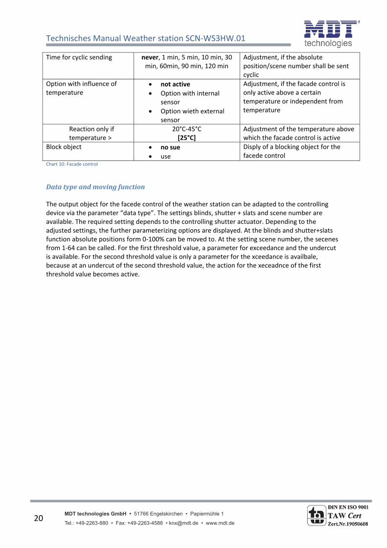
Time for cyclic sending never, 1 min, 5 min, 10 min, 30 min, 60min, 90 min, 120 min
Adjustment, if the absolute position/scene number shall be sent cyclic
Option with influence of temperature
not active
Option with internal sensor
Option wieth external sensor
Adjustment, if the facade control is only active above a certain temperature or independent from temperature
Reaction only if temperature >
20°C‐45°C [25°C]
Adjustment of the temperature above which the facade control is active
Block object no sue
use
Disply of a blocking object for the facede control
Chart 10: Facade control
Datatypeandmovingfunction The output object for the facede control of the weather station can be adapted to the controlling device via the parameter “data type”. The settings blinds, shutter + slats and scene number are available. The required setting depends to the controlling shutter actuator. Depending to the adjusted settings, the further parameterizing options are displayed. At the blinds and shutter+slats function absolute positions form 0‐100% can be moved to. At the setting scene number, the secenes from 1‐64 can be called. For the first threshold value, a parameter for exceedance and the undercut is available. For the second threshold value is only a parameter for the xceedance is availbale, because at an undercut of the second threshold value, the action for the xeceadnce of the first threshold value becomes active.
Technisches Manual Weather station SCN‐WS3HW.01
MDT technologies GmbH • 51766 Engelskirchen • Papiermühle 1 Tel.: +49-2263-880 • Fax: +49-2263-4588 • [email protected] • www.mdt.de
21
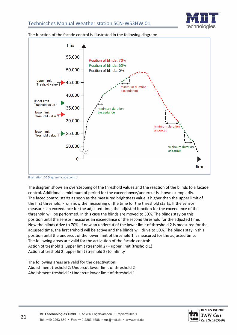
The function of the facade control is illustrated in the following diagram:
Illustration: 10 Diagram facade control
The diagram shows an overstepping of the threshold values and the reaction of the blinds to a facade control. Additional a minimum of period for the exceedanvce/undercut is shown exemplarily. The faced control starts as soon as the measured brightness value is higher than the upper limit of the first threshold. From now the measuring of the time for the threshold starts. If the sensor measures an exceedance for the adjusted time, the adjusted function for the exceedance of the threshold will be performed. In this case the blinds are moved to 50%. The blinds stay on this position until the sensor measures an exceedance of the second threshold for the adjusted time. Now the blinds drive to 70%. If now an undercut of the lower limit of threshold 2 is measured for the adjusted time, the first trehold will be active and the blinds will drive to 50%. The blinds stay in this position until the undercut of the lower limit of threshold 1 is measured for the adjusted time. The following areas are valid for the activation of the facade control: Action of treshold 1: upper limit (treshold 2) – upper limit (treshold 1) Action of treshold 2: upper limit (treshold 2) to infinity The following areas are valid for the deactivation: Abolishment treshold 2: Undercut lower limit of threshold 2 Abolishment treshold 1: Undercut lower limit of threshold 1

Technisches Manual Weather station SCN‐WS3HW.01
MDT technologies GmbH • 51766 Engelskirchen • Papiermühle 1 Tel.: +49-2263-880 • Fax: +49-2263-4588 • [email protected] • www.mdt.de
22
The chart shows the relevant communication objects of the facade control:
Number Name Function Length Usage6 Facade East Send position of blinds 1 Byte Call of the parameterized blind
position
6 Facade East Scene 1 Byte Call of the parameterized scene number
6 Facade East Send shutter position 1 Byte Call of the parametreized shutter position
7 Facade East Send position of slats 1 Byte Call of the parametrized slat position
23 Facade South Send position of blinds 1 Byte Call of the parameterized blind position
23 Facade South Scene 1 Byte Call of the parameterized scene number
23 Facade South Send shutter position 1 Byte Call of the parametreized shutter position
24 Facade South Send position of slats 1 Byte Call of the parametrized slat position
40 Facade West Send position of blinds 1 Byte Call of the parameterized blind position
40 Facade West Scene 1 Byte Call of the parameterized scene number
40 Facade West Send shutter position 1 Byte Call of the parametreized shutter position
41 Facade West Send position of slats 1 Byte Call of the parametrized slat position
Chart 11: Communication objects facade control

Technisches Manual Weather station SCN‐WS3HW.01
MDT technologies GmbH • 51766 Engelskirchen • Papiermühle 1 Tel.: +49-2263-880 • Fax: +49-2263-4588 • [email protected] • www.mdt.de
23
Teach‐InFunktion The Teach‐In function enables the weather station to read the current position of the shutter actuator back. Three objects at the blind function and four objects at the shutter function are available for this function. The objects are shown at the following chart:
Number Name Usage Length Usage9 Facade East Teach‐In position 1 1 Bit Activation of the Teach‐In function
for the first threshold value
10 Facade East Teach‐In position 2 1 Bit Activation of the Teach‐In function for the second threshold value
11 Facade East Status blinds for Teach‐In
1 Byte reads the current value of the blinds from the shutter actuator back
11 Facade East Status shutter for Teach‐In
1 Byte reads the current value of the shutter from the shutter actuator back
12 Facade East Status slats for Teach‐In
1 Byte reads the current value of the slats from the shutter actuator back
26 Facade South Teach‐In position 1 1 Bit Activation of the Teach‐In function for the first threshold value
27 Facade South Teach‐In position 2 1 Bit Activation of the Teach‐In function for the second threshold value
28 Facade South Status blinds for Teach‐In
1 Byte reads the current value of the blinds from the shutter actuator back
28 Facade South Status shutter for Teach‐In
1 Byte reads the current value of the shutter from the shutter actuator back
29 Facade South Status slats for Teach‐In
1 Byte reads the current value of the slats from the shutter actuator back
43 Facade West Teach‐In position 1 1 Bit Activation of the Teach‐In function for the first threshold value
44 Facade West Teach‐In position 2 1 Bit Activation of the Teach‐In function for the second threshold value
45 Facade West Status blinds for Teach‐In
1 Byte reads the current value of the blinds from the shutter actuator back
45 Facade West Status shutter for Teach‐In
1 Byte reads the current value of the shutter from the shutter actuator back
46 Facade West Status slats for Teach‐In
1 Byte reads the current value of the slats from the shutter actuator back
Chart 12: Communication objects Teach‐In
The 1 bit object, Teach‐In position 1/2, is used for the activation of the Teach‐In function and the depending state object is used for reading the current position back. The state object must be connected with the state object of the shutter actuator to read the current position. The following illustration shows an exemplary programming of the Teach‐In function for the shutter and slats:

Technisches Manual Weather station SCN‐WS3HW.01
MDT technologies GmbH • 51766 Engelskirchen • Papiermühle 1 Tel.: +49-2263-880 • Fax: +49-2263-4588 • [email protected] • www.mdt.de
24
Illustration 11: Programming Teach‐In function
The illustration shows the fragmentation of the Teach‐In objects into four different group addresses. The state objects for the Teach‐In function are connected with the state objects of the channel, which is to be controlled, of the shutter actuator. At this example, the 1 bit activation objects, Teach‐In position 1 & 2, are connected with a push‐Button. It is also possible to connect them with a display or anything else. As soon as the push‐button sends a logical “1”, e.g. the button 1 to the Teach‐In position 1, the weather station reads the current position of the shutter actuator from the state objects and overwrites the values for the facade controlling with these values. At a new activation of the facade control, the weather station sends the new values and the shutter/slats drive to this position. There is an additional parameter at the general settings, have a look at page 10, which defines whether the Teach‐In values shall be kept after a new programming or the weather station shall overwrite them with the parameterized one.
Temperature‐/Blockfunction The facade control can also be parameterized with the influence of temperature. This enables that the facade control gets only active if the temperature is higher than a certain value. The temperature can be read from the internal temperature sensor or from any external. An additional communication object appears if the weather station shall receive an external temperature. The connection to the internal sensor occurs automatically if activated. By activation this function, the faced control is only active above the parameterized temperature. If the temperature falls below the adjusted function, the facade control is deactivated. The blocking object for the facade control allows blocking the facade control with a logical “1”. The following chart shows the relevant communication objects:

Technisches Manual Weather station SCN‐WS3HW.01
MDT technologies GmbH • 51766 Engelskirchen • Papiermühle 1 Tel.: +49-2263-880 • Fax: +49-2263-4588 • [email protected] • www.mdt.de
25
Number Name Function Length Usage8 Facade East Block object for facade 1 Bit Blocks the facade control
13 Facade East External temperature 1 Bit Input for an external temperature
25 Facade South Block object for facade 1 Bit Blocks the facade control
30 Facade South External temperature 1 Bit Input for an external temperature
42 Facade West Block object for facade 1 Bit Blocks the facade control
47 Facade West External temperature 1 Bit Input for an external temperature Chart 13: Communication objects temperature‐/block function

Technisches Manual Weather station SCN‐WS3HW.01
MDT technologies GmbH • 51766 Engelskirchen • Papiermühle 1 Tel.: +49-2263-880 • Fax: +49-2263-4588 • [email protected] • www.mdt.de
26
4.3Dusksensor The following illustration shows the setting option for the dusk sensor:
Illustration 12: Dusk sensor
The following chart shows the dynamic range for this parameter:
ETS‐Text Dynamic range [default value]
Comment
Send dusk value [Lux] never
on demand
at change
cyclic
at change and cyclic
defines the sending condition for the dusk sensor
Send dusk value by change of
10%
20%
30%
if the dusk value is sent at change, the minimum rate of change can be defined here
Send dusk value in interval of
10 sec, 20 sec, 30 sec, 1 min, 2 min, 5 min, 10 min, 20 min, 30
min, 45 min, 60 min
if the dusk value is sent cyclic, the timebase for sending can be defined here
Day/Night object not active
day=1 night=0
day=0 night=1
activates the Day/Night object Adjustment of the polarity
Day at Lux value > …Lux
0‐850 [25]
defines the threshold above which day is
Night at Lux value < …Lux
0‐260 [10]
defines the threshold below which night is
Time for cyclic sending
no send, 10 sec, 20 sec, 30 sec, 1 min, 2 min, 5 min, 10 min, 20 min, 30 min, 45 min, 60 min
activates cyclic sending of the Day/Night object and defines the time for cyclic sending
Technisches Manual Weather station SCN‐WS3HW.01
MDT technologies GmbH • 51766 Engelskirchen • Papiermühle 1 Tel.: +49-2263-880 • Fax: +49-2263-4588 • [email protected] • www.mdt.de
27
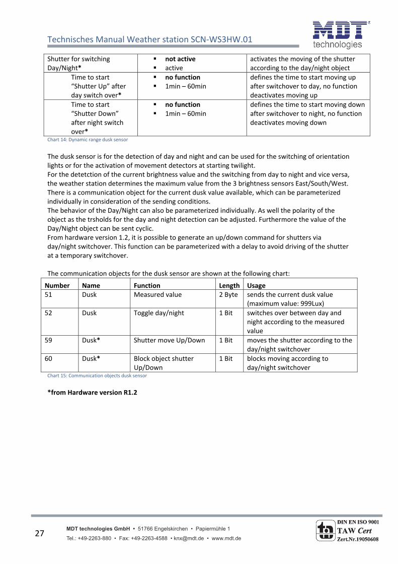
Shutter for switching Day/Night*
not active active
activates the moving of the shutter according to the day/night object
Time to start “Shutter Up” after day switch over*
no function 1min – 60min
defines the time to start moving up after switchover to day, no function deactivates moving up
Time to start “Shutter Down” after night switch over*
no function 1min – 60min
defines the time to start moving down after switchover to night, no function deactivates moving down
Chart 14: Dynamic range dusk sensor
The dusk sensor is for the detection of day and night and can be used for the switching of orientation lights or for the activation of movement detectors at starting twilight. For the detetction of the current brightness value and the switching from day to night and vice versa, the weather station determines the maximum value from the 3 brightness sensors East/South/West. There is a communication object for the current dusk value available, which can be parameterized individually in consideration of the sending conditions. The behavior of the Day/Night can also be parameterized individually. As well the polarity of the object as the trsholds for the day and night detection can be adjusted. Furthermore the value of the Day/Night object can be sent cyclic. From hardware version 1.2, it is possible to generate an up/down command for shutters via day/night switchover. This function can be parameterized with a delay to avoid driving of the shutter at a temporary switchover. The communication objects for the dusk sensor are shown at the following chart:
Number Name Function Length Usage51 Dusk Measured value 2 Byte sends the current dusk value
(maximum value: 999Lux)
52 Dusk Toggle day/night 1 Bit switches over between day and night according to the measured value
59 Dusk* Shutter move Up/Down 1 Bit moves the shutter according to the day/night switchover
60 Dusk* Block object shutter Up/Down
1 Bit blocks moving according to day/night switchover
Chart 15: Communication objects dusk sensor
*from Hardware version R1.2

Technisches Manual Weather station SCN‐WS3HW.01
MDT technologies GmbH • 51766 Engelskirchen • Papiermühle 1 Tel.: +49-2263-880 • Fax: +49-2263-4588 • [email protected] • www.mdt.de
28
4.4Windsensor The following illustration shows the setting options for the wind sensor:
Illustration 13: Wind sensor
The following chart shows the dynamic range of the wind sensor:
ETS‐Text Dynamic range [default value]
Comment
Send wind speed [m/s] never
on demand
at change
cyclic
at change and cyclic
defines the sending condition for the wind sensor
Send by change of 10%
20%
30%
if the wind speed is sent at change, the minimum rate of change can be defined here
Time for cyclic sending
10 sec, 20 sec, 30 sec, 1 min, 2 min, 5 min, 10 min, 20 min, 30
min, 45 min, 60 min
if the wind speed is sent cyclic, the timebase for sending can be defined here
Technisches Manual Weather station SCN‐WS3HW.01
MDT technologies GmbH • 51766 Engelskirchen • Papiermühle 1 Tel.: +49-2263-880 • Fax: +49-2263-4588 • [email protected] • www.mdt.de
29
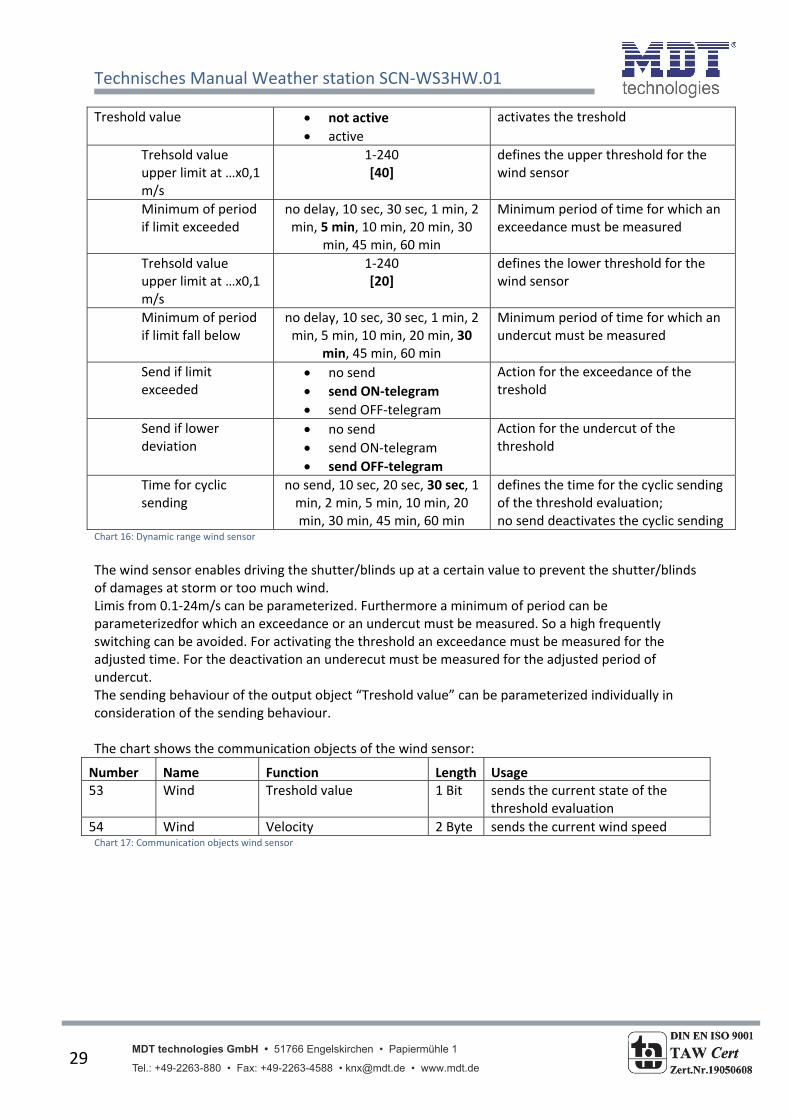
Treshold value not active
active
activates the treshold
Trehsold value upper limit at …x0,1 m/s
1‐240 [40]
defines the upper threshold for the wind sensor
Minimum of period if limit exceeded
no delay, 10 sec, 30 sec, 1 min, 2 min, 5 min, 10 min, 20 min, 30
min, 45 min, 60 min
Minimum period of time for which an exceedance must be measured
Trehsold value upper limit at …x0,1 m/s
1‐240 [20]
defines the lower threshold for the wind sensor
Minimum of period if limit fall below
no delay, 10 sec, 30 sec, 1 min, 2 min, 5 min, 10 min, 20 min, 30
min, 45 min, 60 min
Minimum period of time for which an undercut must be measured
Send if limit exceeded
no send
send ON‐telegram
send OFF‐telegram
Action for the exceedance of the treshold
Send if lower deviation
no send
send ON‐telegram
send OFF‐telegram
Action for the undercut of the threshold
Time for cyclic sending
no send, 10 sec, 20 sec, 30 sec, 1 min, 2 min, 5 min, 10 min, 20 min, 30 min, 45 min, 60 min
defines the time for the cyclic sending of the threshold evaluation; no send deactivates the cyclic sending
Chart 16: Dynamic range wind sensor
The wind sensor enables driving the shutter/blinds up at a certain value to prevent the shutter/blinds of damages at storm or too much wind. Limis from 0.1‐24m/s can be parameterized. Furthermore a minimum of period can be parameterizedfor which an exceedance or an undercut must be measured. So a high frequently switching can be avoided. For activating the threshold an exceedance must be measured for the adjusted time. For the deactivation an underecut must be measured for the adjusted period of undercut. The sending behaviour of the output object “Treshold value” can be parameterized individually in consideration of the sending behaviour. The chart shows the communication objects of the wind sensor:
Number Name Function Length Usage53 Wind Treshold value 1 Bit sends the current state of the
threshold evaluation
54 Wind Velocity 2 Byte sends the current wind speed Chart 17: Communication objects wind sensor
Technisches Manual Weather station SCN‐WS3HW.01
MDT technologies GmbH • 51766 Engelskirchen • Papiermühle 1 Tel.: +49-2263-880 • Fax: +49-2263-4588 • [email protected] • www.mdt.de
30
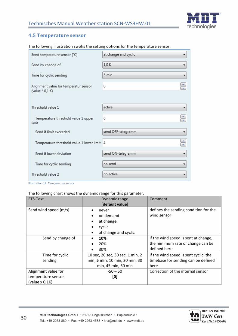
4.5Temperaturesensor The following illustration swohs the setting options for the temperature sensor:
Illustration 14: Temperature sensor
The following chart shows the dynamic range for this parameter:
ETS‐Text Dynamic range [default value]
Comment
Send wind speed [m/s] never
on demand
at change
cyclic
at change and cyclic
defines the sending condition for the wind sensor
Send by change of 10%
20%
30%
if the wind speed is sent at change, the minimum rate of change can be defined here
Time for cyclic sending
10 sec, 20 sec, 30 sec, 1 min, 2 min, 5 min, 10 min, 20 min, 30
min, 45 min, 60 min
if the wind speed is sent cyclic, the timebase for sending can be defined here
Alignment value for temperature sensor (value x 0,1K)
‐50 – 50 [0]
Correction of the internal sensor
Technisches Manual Weather station SCN‐WS3HW.01
MDT technologies GmbH • 51766 Engelskirchen • Papiermühle 1 Tel.: +49-2263-880 • Fax: +49-2263-4588 • [email protected] • www.mdt.de
31
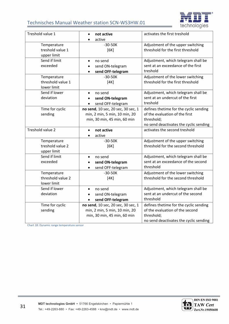
Treshold value 1 not active
active
activates the first treshold
Temperature treshold value 1 upper limit
‐30‐50K [6K]
Adjustment of the upper switching threshold for the first threshold
Send if limit exceeded
no send
send ON‐telegram
send OFF‐telegram
Adjustment, which telegram shall be sent at an exceedance of the first treshold
Temperature threshold value 1 lower limit
‐30‐50K [4K]
Adjustment of the lower switching threshold for the first threshold
Send if lower deviation
no send
send ON‐telegram
send OFF‐telegram
Adjustment, which telegram shall be sent at an undercut of the first treshold
Time for cyclic sending
no send, 10 sec, 20 sec, 30 sec, 1 min, 2 min, 5 min, 10 min, 20 min, 30 min, 45 min, 60 min
defines thetime for the cyclic sending of the evaluation of the first threshold; no send deactivates the cyclic sending
Treshold value 2 not active
active
activates the second treshold
Temperature treshold value 2 upper limit
‐30‐50K [6K]
Adjustment of the upper switching threshold for the second threshold
Send if limit exceeded
no send
send ON‐telegram
send OFF‐telegram
Adjustment, which telegram shall be sent at an exceedance of the second threshold
Temperature threshold value 2 lower limit
‐30‐50K [4K]
Adjustment of the lower switching threshold for the second threshold
Send if lower deviation
no send
send ON‐telegram
send OFF‐telegram
Adjustment, which telegram shall be sent at an undercut of the second threshold
Time for cyclic sending
no send, 10 sec, 20 sec, 30 sec, 1 min, 2 min, 5 min, 10 min, 20 min, 30 min, 45 min, 60 min
defines thetime for the cyclic sending of the evaluation of the second threshold; no send deactivates the cyclic sending
Chart 18: Dynamic range temperature sensor

Technisches Manual Weather station SCN‐WS3HW.01
MDT technologies GmbH • 51766 Engelskirchen • Papiermühle 1 Tel.: +49-2263-880 • Fax: +49-2263-4588 • [email protected] • www.mdt.de
32
The temperature sensor enables the observation of the temperature to switch according to the measured temperature the communication objects. So it is possible to switch heatings or air ventilatins on/off according to the temperature. The measured temperature value can be corrected by this setting “alignment value for temperature sensor”. By choosing a negative value for this parameter, the measured value will be lowered and by choosing a positive value, the measured value will be lifted. The value is multiplied by 0,1K, so the current value can be lowered or lifted up to 5K. This setting is useful, when the sensor measures wrong values. When this function is activated, the temperature controller will also send the corrected values. All sensors are matched in‐plant to 0,1K. Two tresholds are availbale for the parameterization of the temperature sensor, which can send as well for the execeedance as for the undercut switching telegrams. These are done by the communication objects “Status of threshold value 1” and “Status of threshold value 2”. The evaluation of the tresholds can also be done cyclic. The communication objetcs of the temperature sensor are shown at the following chart:
Number Name Function Length Usage55 Temperature Measured value 2 Byte sends the measured value
56 Temperature Status of threshold value 1
1 Bit sends the current state of the first threshold
57 Temperature Status of threshold value 2
1 Bit sends the current state of the second threshold
Chart 19: Communication objects temperature sensor
Technisches Manual Weather station SCN‐WS3HW.01
MDT technologies GmbH • 51766 Engelskirchen • Papiermühle 1 Tel.: +49-2263-880 • Fax: +49-2263-4588 • [email protected] • www.mdt.de
33
5Index
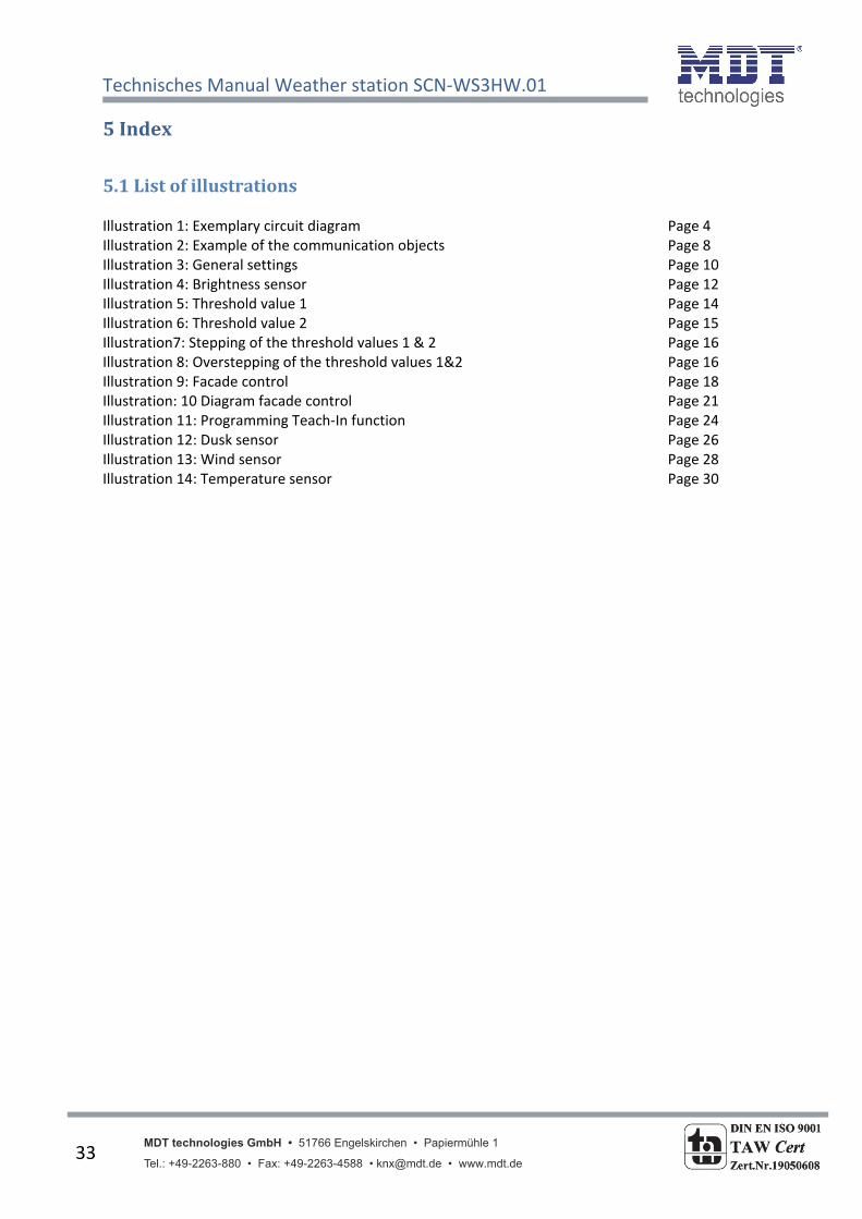
5.1Listofillustrations Illustration 1: Exemplary circuit diagram Page 4 Illustration 2: Example of the communication objects Page 8 Illustration 3: General settings Page 10 Illustration 4: Brightness sensor Page 12 Illustration 5: Threshold value 1 Page 14 Illustration 6: Threshold value 2 Page 15 Illustration7: Stepping of the threshold values 1 & 2 Page 16 Illustration 8: Overstepping of the threshold values 1&2 Page 16 Illustration 9: Facade control Page 18 Illustration: 10 Diagram facade control Page 21 Illustration 11: Programming Teach‐In function Page 24 Illustration 12: Dusk sensor Page 26 Illustration 13: Wind sensor Page 28 Illustration 14: Temperature sensor Page 30

Technisches Manual Weather station SCN‐WS3HW.01
MDT technologies GmbH • 51766 Engelskirchen • Papiermühle 1 Tel.: +49-2263-880 • Fax: +49-2263-4588 • [email protected] • www.mdt.de
34
5.2Listoftables Chart 1: Overview functions Page 6 Chart 2: Default settings of the communication objects Page 9 Chart 3: Parameter – General Page 10 Chart 4: Settings brightness sensor Page 12 Chart 5: Intensity of illumination Page 13 Chart 6: Communication objects brightness sensor Page 13 Chart 7: Settings threshold value 1 Page 14 Chart 8: Settings threshold value 2 Page 15 Chart 9: Communication objects threshold values Page 17 Chart 10: Facade control Page 18 Chart 11: Communication objects facade control Page 22 Chart 12: Communication objects Teach‐In Page 23 Chart 13: Communication objects temperature‐/block function Page 25 Chart 14: Dynamic range dusk sensor Page 26 Chart 15: Communication objects dusk sensor Page 27 Chart 16: Dynamic range wind sensor Page 28 Chart 17: Communication objects wind sensor Page 29 Chart 18: Dynamic range temperature sensor Page 30 Chart 19: Communication objects temperature sensor Page 32
Technisches Manual Weather station SCN‐WS3HW.01
MDT technologies GmbH • 51766 Engelskirchen • Papiermühle 1 Tel.: +49-2263-880 • Fax: +49-2263-4588 • [email protected] • www.mdt.de
35
6.1 Statutory requirements
The above‐described devices must not be used with devices, which serve directly or indirectly the
purpose of human, health‐ or lifesaving. Further the devices must not be used if their usage can
occur danger for humans, animals or material assets.
Do not let the packaging lying around careless, plastic foil/ ‐bags etc. can be a dangerous toy for kids.
6.2 Routine disposal
Do not throw the waste equipment in the household rubbish. The device contains electrical devices,
which must be disposed as electronic scrap. The casing contains of recyclable synthetic material.
6.3 Assemblage
Risk for life of electrical power!
All activities on the device should only be done by an electrical specialist. The county specific
regulations and the applicable EIB‐directives have to be observed.

SCN-SS1H.01
SCN-RS1R.01
MDT Brightness-/Weather devices
Version
SCN-WS3HW.01 Weather Station Home Outdoor installation on wall or pole, flush mounted control unit
SCN-SS1H.01 Sun Sensor Indoor installation with vacuum cup, flush mounted control unit
SCN-RS1R.01 Rain Sensor Outdoor installation, Surface mounted
MDT technologies offers three Brightness / Weather devices:
Wetter Station Home: • 3 channels for sun protection to control blind/shutter • Sun protection up to 3 facades • Offers wide functions to control facades (2 switching treshold, teach in function) • Central shutter control for Up/Down via brightness value (with time delay)
• Brightness value for east, south, west, twilight• Wind speed value, alarm if wind speed exceeds limit, temperature value• Suited to control facades at home• Installation on wall or pole, 5m connection cable• No additional power supply required• Integrated bus coupling unit • 3 years warranty
Sun Sensor: Rain Sensor: • Brightness sensor with vacuum for window installation • Integrated, automatically heating
• 2 inputs to connect push button for blind control • Heating operation by choke free output STV-640 • Hysteresis and time delay programmable or external 24VDC power supply• 2m connection cable • Current consumption of heating is <100mA• Flush mounted control unit • 5m bus connection cable• Operation mode 1: Installation on window without blinds • Stainless fastening angle included in delivery • Operation mode 2: Installation on window with blinds • Dimensions (W x H x D): 67mm x 67mm x 29mm• No additional power supply required • Integrated bus coupling unit• Integrated bus coupling unit in control unit • 3 years warranty• 3 years warranty For project design and commissioning of the Brightness/Weather devices it is recommended to use the ETS3f/ETS4 or later. Please download the application software at www.mdt.de/Downloads.html
• Integrated bus coupling unit • 3 years warranty
• Production in Germany, certified according to ISO 9001• Modern design• Fully compatible to all KNX/EIB devices
MDT Brightness/Weather
SCN-WS3HW.01
MDT technologies GmbH • 51766 Engelskirchen • Papiermühle 1
Tel.: + 49 - 2263 - 880 • Fax: + 49 - 2263 - 4588 • [email protected] • www.mdt.de
Stand: 0713
DIN EN ISO 9001
TAW Cert Zert.Nr.1905606
N

MDT Brightness/Weather
Technical Data SCN-SS1H.01 SCN-WS3HW.01 SCN-RS1R.01
Measured data BrightnessBrightness, Wind,
Twilight, TemperatureRain
Twilight range 0 - 1000 lux 0 - 1000 lux --
Daylight range 0- 100000 lux 0- 100000 lux --
Temperature range* -- -30°C to + 70°C --
Windspeed range -- 0 - 32 m/s --
Permitted wire gauge
KNX busconnection 0,8mm Ø, solid core 0,8mm Ø, solid core 0,8mm Ø, solid core
Power supply KNX Bus KNX Bus KNX Bus
Power consumption via KNX bus typ. < 0,3W < 0,3W < 0,3W**
Operation temperature range 0 to + 45°C -20 to + 70°C 0 to + 45°C
Enclosure IP 20 IP 44 IP 45
Dimensions control unit (W x H x D) 41mm x 41mm x 12mm -- 67mm x 67mm x 29mm
Examplary circuit diagram SCN-xSxxx.01
* Depending on mounting position the measured temperature value can be different from real temperature value.** Without heating. Heating operation by choke free output STV 640 or external 24VDC power supply. Current consumption of heating is <100mA
Examplary circuit diagram SCN-RS001.01
MDT technologies GmbH • 51766 Engelskirchen • Papiermühle 1
Tel.: + 49 - 2263 - 880 • Fax: + 49 - 2263 - 4588 • [email protected] • www.mdt.de
Stand: 0713
DIN EN ISO 9001
TAW Cert Zert.Nr.1905606
N