Embed Size (px)
Citation preview
Check Point MDSM with VSX
Infrastructure Architecture Recommendations
and
Configuration Guide
PREPARED FOR
Piggy Bank
1 | P a g e V l a d i m i r Y a k o v l e v
Contents Creating and configuring MDSM infrastructure ..................................................................................................................... 2
Assets .................................................................................................................................................................................. 2
Intermediate and final phases of building Check Point security infrastructure ................................................................. 2
Security of the MDSMs and MDSLs..................................................................................................................................... 3
Assuring availability of MDSM and VSX management connections ................................................................................... 4
Segmentation of the Check Point management infrastructure .......................................................................................... 5
Logging structure ................................................................................................................................................................ 6
Logging to external SIEM (Security Information and Event Management) solutions......................................................... 8
Policy sources and fetching order ..................................................................................................................................... 10
Configuring Gaia parameters of MDSM and VSX Infrastructure components ..................................................................... 11
Common Gaia Configuration parameters ......................................................................................................................... 11
Configuring Multi-Domain Servers and Multi-Domain Log Servers .................................................................................. 15
Configuring Primary Multi-Domain Server .................................................................................................................... 15
Configuring Secondary Multi-Domain Server(s) ............................................................................................................ 18
Configuring Multi-Domain Log Server(s) ....................................................................................................................... 19
Configuring VSX cluster members ..................................................................................................................................... 20
Completing Common Gaia Configuration ......................................................................................................................... 22
VSX WebUI Window of Opportunity ................................................................................................................................. 24
Installing Check Point Management Console(s) and connecting to MDS’ ............................................................................ 25
Defining GUI Clients for MDSM infrastructure ................................................................................................................. 30
Adding MDSM components to Multi-Domain Security Management infrastructure .......................................................... 32
Creating Domains .................................................................................................................................................................. 36
Connecting to Domain Management Server .................................................................................................................... 40
Configuring Domain Management High Availability ......................................................................................................... 44
Configuring Domain Log Servers ....................................................................................................................................... 46
Enabling SmartLog in the domain contents ................................................................................................................... 50
Configuring VSX HA Clusters ................................................................................................................................................. 52
Configuring Virtual Systems .................................................................................................................................................. 62
Restoring Domain Management Server content .................................................................................................................. 67
Sanitizing exported DMS data for new environments ...................................................................................................... 68
Configuring SNMP monitoring for MDSM infrastructure components ................................................................................ 69
2 | P a g e V l a d i m i r Y a k o v l e v
Creating and configuring MDSM infrastructure
Since you are in the early stages of migration to your new MDSM infrastructure, it is imperative to take maximum
advantage of opportunity to set it up in the way that will address all three major concerns of security conscious design:
confidentiality, integrity, and availability.
To that end, let’s analyze the components that comprise your entire MDSM and VSX infrastructure, its physical
connectivity, protection, accessibility, redundancy, and the flow of data between its components.
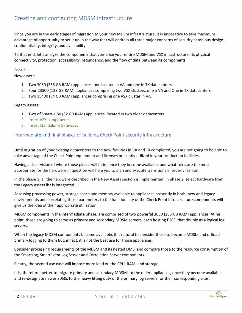
Assets New assets:
1. Two 3050 (256 GB RAM) appliances, one located in VA and one in TX datacenters.
2. Four 23500 (128 GB RAM) appliances comprising two VSX clusters, one n VA and One in TX datacenters.
3. Two 15400 (64 GB RAM) appliances comprising one VSX cluster in VA.
Legacy assets:
1. Two of Smart-1 50 (32 GB RAM) appliances, located in two older datacenters.
2. Insert VSX components
3. Insert Standalone Gateways
Intermediate and final phases of building Check Point security infrastructure
Until migration of your existing datacenters to the new facilities in VA and TX completed, you are not going to be able to
take advantage of the Check Point equipment and licenses presently utilized in your production facilities.
Having a clear vision of where those pieces will fit in, once they become available, and what roles are the most
appropriate for the hardware in question will help you to plan and execute transitions in orderly fashion.
In the phase 1, all the hardware described in the New Assets section is implemented. In phase 2, select hardware from
the Legacy assets list is integrated.
Assessing processing power, storage space and memory available to appliances presently in both, new and legacy
environments and correlating those parameters to the functionality of the Check Point infrastructure components will
give us the idea of their appropriate utilization.
MDSM components in the intermediate phase, are comprised of two powerful 3050 (256 GB RAM) appliances. At his
point, those are going to serve as primary and secondary MDSM servers, each hosting DMS’ that double as a logical log
servers.
When the legacy MDSM components become available, it is natural to consider those to become MDSLs and offload
primary logging to them but, in fact, it is not the best use for those appliances.
Consider processing requirements of the MDSM and its nested DMS’ and compare those to the resource consumption of
the SmartLog, SmartEvent Log Server and Correlation Server components.
Clearly, the second use case will impose more load on the CPU, RAM, and storage.
It is, therefore, better to migrate primary and secondary MDSMs to the older appliances, once they become available
and re-designate newer 3050s to the heavy lifting duty of the primary log servers for their corresponding sites.
3 | P a g e V l a d i m i r Y a k o v l e v
Security of the MDSMs and MDSLs
While it may not be immediately apparent, your MDS and MDLS servers themselves are not secured. Besides
rudimentary access control of Gaia configuration, there are no firewalls that protect the MDSM components. Even if
both of your management networks, in VA and TX are behind firewalls, these statements are still true:
1. You do not have the ability to protect MDS and MDLS with more complex security applications, such IPS, AV, etc.
from lateral threats within your management network(s).
2. You do not have the logging capability to be even aware of the security events taking place inside your
management network, (such as port scans, protocol fuzzing MAC and ARP poisoning, etc.)
MDSM components themselves contain Audit Logs that will indicate successful and unsuccessful logon attempts and
management events, but this is the extent of their own logging capabilities.
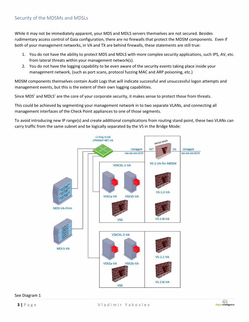
Since MDS’ and MDLS’ are the core of your corporate security, it makes sense to protect those from threats.
This could be achieved by segmenting your management network in to two separate VLANs, and connecting all
management interfaces of the Check Point appliances to one of those segments.
To avoid introducing new IP range(s) and create additional complications from routing stand point, these two VLANs can
carry traffic from the same subnet and be logically separated by the VS in the Bridge Mode:
See Diagram 1

4 | P a g e V l a d i m i r Y a k o v l e v
Assuring availability of MDSM and VSX management connections
You are obviously concerned about redundancy of the components of your Check Point security infrastructure, which is
apparent from the presence of VSX clusters.
Same approach should be taken to the availability of the connectivity to the management interfaces of the components
of this infrastructure.
Since you have already started deploying VSX clusters and underlying VS’ it may be difficult to accomplish at this point,
but it is important for you to understand the implication of NOT having it in place:
Presently, you only have a single management interface from each appliance connected to the same switch in their
corresponding racks. This may be suitable for the LOM ports of the appliances, but it also creates a single point of
failure.
If you are to lose the switch that provides connectivity to the management interfaces, for the duration of the switches’
downtime following will take place:
1. If the failure of the switch that the management interfaces are connected to happen in the rack containing
3050*:
a. VSX members will failover to the units in the other rack.
b. Presently, VSXs and underlying VS’ will begin forwarding logs to the other site.
c. You’ll have to make DMS’ in the other site “active” to perform policy modifications.
d. You’ll have to make MDS “active” to perform Global operations.
*This will work only if both switches used for management network have an independent egress to the rest
of your routing infrastructure.
2. If the failure of the switch that the management interfaces are connected to happen in the rack NOT containing
3050:
a. If the devices in that rack were designated as “standby” no complications will transpire.
b. If the devices in that rack were designated as “active”, they will failover to the devices in other rack.
In the 1st case, you will not be able to:
a. Manage MDS, MDLS, DMS’, VSXs and VS’ in the rack the outage has occurred in.
b. Receive, forward and analyze log events generated by those appliances and virtual systems they contain.
…using 3050 that is still running normally, but have lost its’ single management connection.
Creating a bond of the Mgmt and one of the 1GBE interfaces, designating that bond as a Management interface and
connecting secondary ports to another switch in the same rack containing management VLAN for all Check Point
appliances, should allow your infrastructure to function uninterrupted and avoid loss of connectivity and real-time
logging capability at the same site.
Note: You may still be able to perform these operations once the legacy appliances will be ready for deployment in
production environment if: you perform a sequential failover to HA members, remove IPs from existing management
interfaces, create new bonds, define them as new management interfaces with same IPs, and updating topology of the
objects in the MDS’ and DMS’ and defining proper anti-spoofing parameters on new bonded interfaces.
!!!You can only perform these operations if either LOM or the Console Server connectivity are in place!!!

5 | P a g e V l a d i m i r Y a k o v l e v
Segmentation of the Check Point management infrastructure
Since your infrastructure contains multiple segments and is managed by multiple security administrators, certain
precautions should be taken to assure that the accidental or intentional adverse management events will not happen.
In addition to defining administrator’s roles in the MDSM that will limit their ability to introduce unwanted configuration
changes, it is also a good practice, licensing permitting, to segregate management functions protecting core MDSM and
VSX components.
By doing it, you will not only limit segment administrators’ rites to perform actions, but will be able to conceal the
underlying topology of your core infrastructure from the people that may have no Need to Know about its’ inner
working.
Added benefit of this approach is the limitation of log events generated by the components comprising these segregated
domains: everything these logs contain will be pertinent to the core functionality of the Check Point infrastructure.
Therefore, analysis and troubleshooting of it will not require sifting through the busy logs of the production execution
segments.
Following architecture is based on the information received from Client Representative’s Name, specifying that the
single domain structure will be utilized for overall management. Proposed solution is intended to take advantage of
licenses already purchased with appliances.
See Diagram 2
If, later, you will consolidate your existing licenses and have one more DMS HA, you can split the VA and TX VS’ in two
different domains with local “active” DMS with the “standby” located at the other site to improve latency.
(active) (standby)
(standby) (active)
(active) (standby)
(standby) (active)
(active) (standby)
VS-N-XX
These elements comprise the rest of the
execution domain and contain its
Management Servers and the rest of the
Virtual SystemsVS-1.3-TX
VS-1.4-TX
These elements are
protecting your core security
infrastructure
VSXCXL-1-VA
VSXCXL-2-VA
VS-1-TX-for-MDSM
VS-2.2-VA
VS-2.3-VA
VS2.4-VA
VSXCXL-1-TX
VS-1.2-VA
VS-1.3-VA
VS-1.4-VA
VS-1.2-TX
Check Point MDSM Architecture
MDS-VA
Primary
MDS-TX
DMS-4-VA DMS-4-TX
DMS-2-VA
DMS-1-TX
DMS-2-TX
DMS-1-VA
Secondary
DMS-5-VA DMS-5-TX
DMS-3-VA DMS-3-TX
VS-1-VA-for-MDSM
6 | P a g e V l a d i m i r Y a k o v l e v
Logging structure
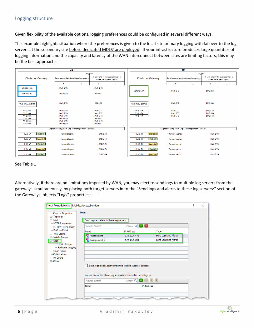
Given flexibility of the available options, logging preferences could be configured in several different ways.
This example highlights situation where the preferences is given to the local site primary logging with failover to the log
servers at the secondary site before dedicated MDLS’ are deployed. If your infrastructure produces large quantities of
logging information and the capacity and latency of the WAN interconnect between sites are limiting factors, this may
be the best approach:
See Table 1
Alternatively, if there are no limitations imposed by WAN, you may elect to send logs to multiple log servers from the
gateways simultaneously, by placing both target servers in to the “Send logs and alerts to these log servers:” section of
the Gateways’ objects “Logs” properties:
7 | P a g e V l a d i m i r Y a k o v l e v
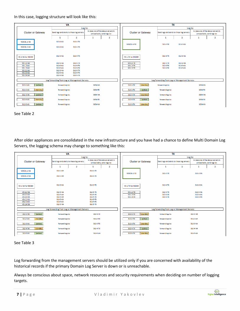
In this case, logging structure will look like this:
See Table 2
After older appliances are consolidated in the new infrastructure and you have had a chance to define Multi Domain Log
Servers, the logging schema may change to something like this:
See Table 3
Log forwarding from the management servers should be utilized only if you are concerned with availability of the
historical records if the primary Domain Log Server is down or is unreachable.
Always be conscious about space, network resources and security requirements when deciding on number of logging
targets.

8 | P a g e V l a d i m i r Y a k o v l e v
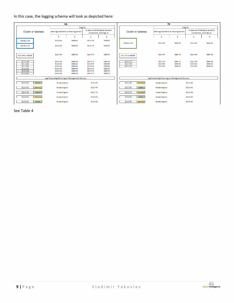
Logging to external SIEM (Security Information and Event Management) solutions
If you are employing SIEM solutions other than Check Point SmartEvent and depending on its capabilities, you may have
to forward firewall logs to those not in the native Check Point format, but as a standard Syslog. As of 77.30 you have an
opportunity to do so by creating a normal host object with syslog’s IP assigned to it and then creating a Syslog Server
Object in the Servers and OPSEC section of the Objects window.
In the Syslog Properties, assign the host created in the previous step, specify port you are using for communication to
SIEM and chose Version of the Protocol.
Once the steps described above are completed, your newly created Syslog Server appears in the list of possible targets
for log forwarding in the Check Point Gateway’s properties:
See Check Point sk87560 for references.
9 | P a g e V l a d i m i r Y a k o v l e v
In this case, the logging schema will look as depicted here:
See Table 4
10 | P a g e V l a d i m i r Y a k o v l e v
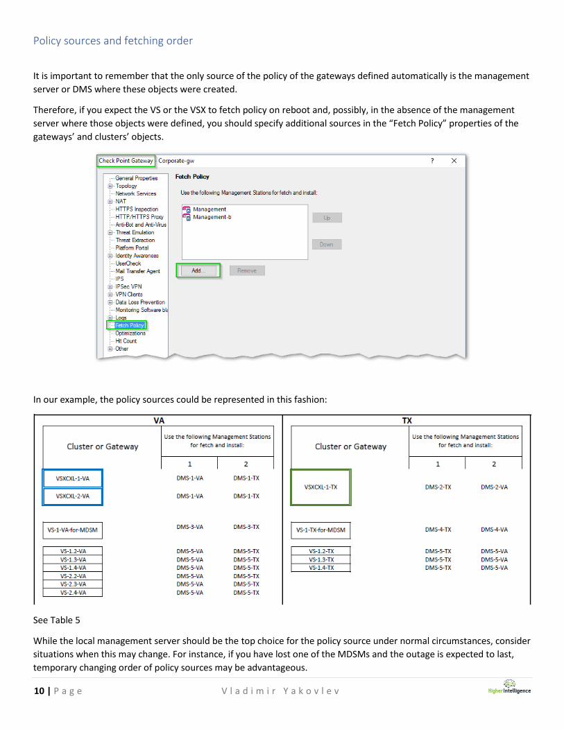
Policy sources and fetching order
It is important to remember that the only source of the policy of the gateways defined automatically is the management
server or DMS where these objects were created.
Therefore, if you expect the VS or the VSX to fetch policy on reboot and, possibly, in the absence of the management
server where those objects were defined, you should specify additional sources in the “Fetch Policy” properties of the
gateways’ and clusters’ objects.
In our example, the policy sources could be represented in this fashion:
See Table 5
While the local management server should be the top choice for the policy source under normal circumstances, consider
situations when this may change. For instance, if you have lost one of the MDSMs and the outage is expected to last,
temporary changing order of policy sources may be advantageous.

11 | P a g e V l a d i m i r Y a k o v l e v
Configuring Gaia parameters of MDSM and VSX Infrastructure components
Common Gaia Configuration parameters
1. Depending on whether your installation is happening on a physical platform or a virtual one, you may have to go
through the Gaia ISO image installation. You may also encounter this situation if you are re-installing the OS on
the appliances from the USB drive.
If you are prompted with the series of the VGA configuration choices, define language, input, network
parameters for the initial configuration and password for the first-time access of WebUI.
Note that all of these parameters defined by this point could be changed via WebUI, once it is accessible.
Complete installation, noting the assigned IP address and reboot the appliance.
2. Using web browser, logon to the appliance for the first time via URL https://<IP_address_assigned_earlier> or
specified in the appliance’s documentation, accepting notification about invalid certificate.
3. If this is a new management appliance, it is likely configured with R80 version of the Check Point pre-configured
as primary boot image. You have an option to select “Revert to R77.30”. Choose that and confirm to revert.
After boot image reverts to R77.30, appliance will reboot. Wait for reboot to complete and proceed to the next
step. Note that it takes approximately 10 minutes for the appliance to revert to a different boot image.

12 | P a g e V l a d i m i r Y a k o v l e v
4. Enter administrative credentials using same password you have assigned earlier, or default password “admin”,
using “admin” as a user name:
5. You are prompted with the “Welcome screen” of the “First-Time Configuration Wizard”, click “Next” to
continue:

13 | P a g e V l a d i m i r Y a k o v l e v
6. Make appropriate selection for your deployment option and click next:
7. Confirm or change the IP address and the subnet mask assigned to the interface you are connected to:
Note, that should you decide to change the IP address at this point, an alias, or secondary IP will be assigned by Gaia
to the same management interface. You can delete the original IP address, once you have reconnected to the
appliance using the new one.
14 | P a g e V l a d i m i r Y a k o v l e v
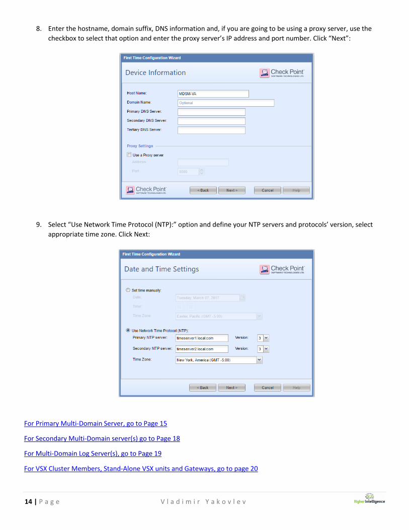
8. Enter the hostname, domain suffix, DNS information and, if you are going to be using a proxy server, use the
checkbox to select that option and enter the proxy server’s IP address and port number. Click “Next”:
9. Select “Use Network Time Protocol (NTP):” option and define your NTP servers and protocols’ version, select
appropriate time zone. Click Next:
For Primary Multi-Domain Server, go to Page 15
For Secondary Multi-Domain server(s) go to Page 18
For Multi-Domain Log Server(s), go to Page 19
For VSX Cluster Members, Stand-Alone VSX units and Gateways, go to page 20

15 | P a g e V l a d i m i r Y a k o v l e v
Configuring Multi-Domain Servers and Multi-Domain Log Servers
Configuring Primary Multi-Domain Server
10. Select “Multi-Domain Server” and click “Next”:
11. Confirm that the Primary Multi-Domain Server option is selected and that the option of “Automatically
Download Blade Contracts and other important data” checkbox is filled per your requirements. Click “Next”:

16 | P a g e V l a d i m i r Y a k o v l e v
12. In the “Leading VIP Interface Configuration” window, chose the interface you are designating as your first
Leading VIP. Normally, it will be a “Mgmt” interface on the hardware appliances. Click “Next”:
13. Make an initial selection of the GUI clients permitted to access your host. These parameters could be later
adjusted in WebUI. Unless warranted, leave selection at “Any host” and click “Next”:

17 | P a g e V l a d i m i r Y a k o v l e v
14. Create a Security Management Administrator’s account and assign strong complex password to it. Click “Next”:
15. Unless permitted by your security policy, uncheck the “Improve product experience by sending data to Check
Point” and click “Finish”:
16. When prompted for the confirmation of the beginning of the configuration process, click “Yes”:
To continue, go to Page 22

18 | P a g e V l a d i m i r Y a k o v l e v
Configuring Secondary Multi-Domain Server(s)
1. When prompted with “Installation Type”, select “Secondary Multi-Domain Server” and click “Next”:
2. Make appropriate choices for “Leading VIP Interface Configuration” and click “Next.
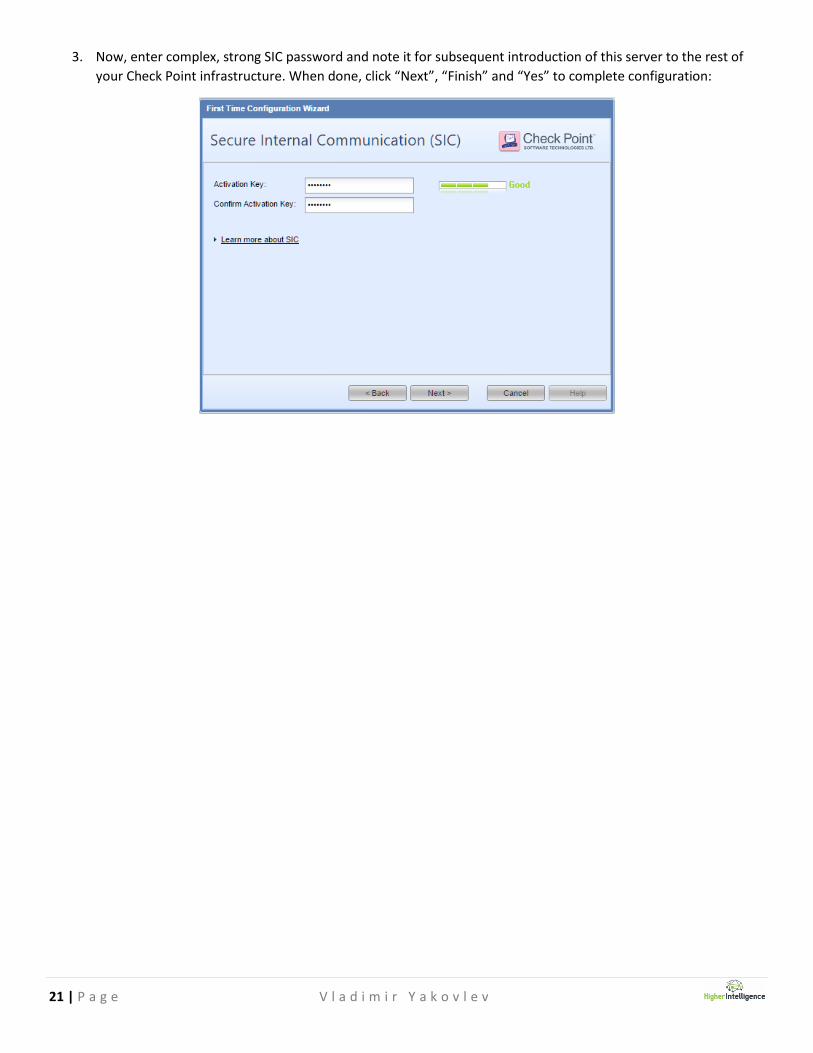
3. Now, enter complex, strong SIC password and note it for subsequent introduction of this server to the rest of
your Check Point infrastructure. When done, click “Next”, “Finish” and “Yes” to complete configuration:
To continue, go to Page 22
19 | P a g e V l a d i m i r Y a k o v l e v
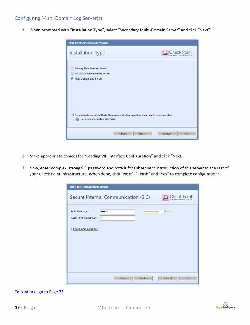
Configuring Multi-Domain Log Server(s)
1. When prompted with “Installation Type”, select “Secondary Multi-Domain Server” and click “Next”:
2. Make appropriate choices for “Leading VIP Interface Configuration” and click “Next.
3. Now, enter complex, strong SIC password and note it for subsequent introduction of this server to the rest of
your Check Point infrastructure. When done, click “Next”, “Finish” and “Yes” to complete configuration:
To continue, go to Page 22
20 | P a g e V l a d i m i r Y a k o v l e v
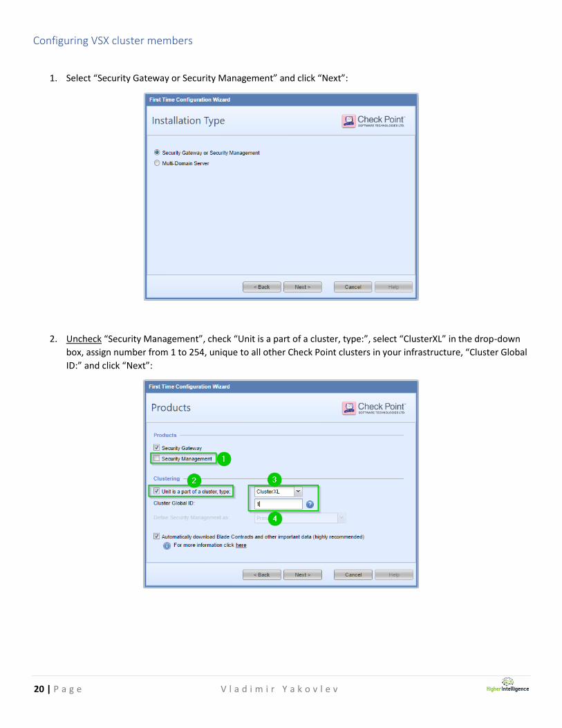
Configuring VSX cluster members
1. Select “Security Gateway or Security Management” and click “Next”:
2. Uncheck “Security Management”, check “Unit is a part of a cluster, type:”, select “ClusterXL” in the drop-down
box, assign number from 1 to 254, unique to all other Check Point clusters in your infrastructure, “Cluster Global
ID:” and click “Next”:
21 | P a g e V l a d i m i r Y a k o v l e v
3. Now, enter complex, strong SIC password and note it for subsequent introduction of this server to the rest of
your Check Point infrastructure. When done, click “Next”, “Finish” and “Yes” to complete configuration:
22 | P a g e V l a d i m i r Y a k o v l e v
Completing Common Gaia Configuration
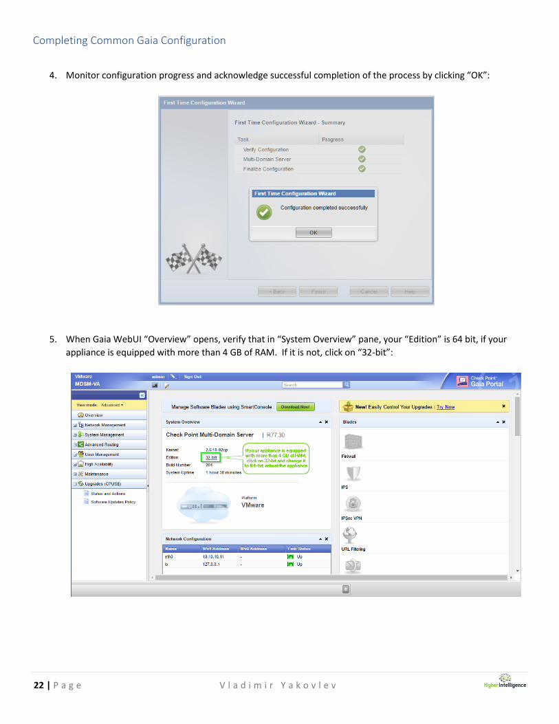
4. Monitor configuration progress and acknowledge successful completion of the process by clicking “OK”:
5. When Gaia WebUI “Overview” opens, verify that in “System Overview” pane, your “Edition” is 64 bit, if your
appliance is equipped with more than 4 GB of RAM. If it is not, click on “32-bit”:

23 | P a g e V l a d i m i r Y a k o v l e v
6. In resultant window, chose “64-bit” option and click “Apply”. Note that the reboot will be required:
7. Confirm reboot when prompted by clicking “Yes”:
8. Logon to the appliance once it is rebooted and verify that the “Edition” value is now “64-bit”:

24 | P a g e V l a d i m i r Y a k o v l e v
9. If you have a desired HFA version or a specific or custom patch, that all your appliances should have installed
prior to deployment in production, perform installation now. If the appliance does not have the Internet access
at this point, perform an offline installation and updates. Some of the HFAs or patches may require higher
version of the Deployment Agent than presently installed on the appliance. If this is the case, perform the
update of the Deployment Agent prior to installation of HFAs or patches.
10. If at any time your session times out and after logon you will see the small lock icon between administrator’s
name and “Sign Out” option closer to the top-left of the blue edge of the screen:
Click on it to acquire session lock. Click “Yes” to confirm:
The lock icon will turn in to a pen icon indicating successful lock acquisition.
VSX WebUI Window of Opportunity
At this point in your initial configuration, you have an opportunity to utilize WebUI for future VSX cluster members to
configure additional parameters, such as networking (including bonded interfaces and VLAN sub-interfaces), SNMP,
roles for administration, routing etc...
Once cluster candidates are added to the cluster object, your ability for further configuration adjustments will be limited
strictly to a combination of command line interface and the manipulation of the cluster object via SmartDashboard.
If you prefer visual feedback for this phase of deployment, having configuration of cluster members pre-planned will
help you maximize the utilization of the WebUI functionality.
Consider also the possibility of using WebUI to generate complex settings and then export, modify and import those via
CLISH to the systems that are already are cluster members.

25 | P a g e V l a d i m i r Y a k o v l e v
Installing Check Point Management Console(s) and connecting to MDS’
Your Check Point administrators must install SmartConsole applications on their Windows PCs to administer either
MDSM infrastructure or its components. While each Check Point appliance’s WebUI offers an option to download
SmartConsole application directly from it, the recommended option is to download installation package from Check
Point User center.
The reason for this is that the package downloaded from appliances contains dependencies to C++ and .Net runtime
environments, whereas package downloaded from User Center has those embedded.
Current version of SmartConsole for Windows 10, sk110892 could be found at:
https://supportcenter.checkpoint.com/supportcenter/portal?eventSubmit_doGoviewsolutiondetails=&solutionid=sk110
892&partition=General&product=SmartConsole
The name of the file is: Check_Point_SmartConsole_and_SmartDomain_Manager_R77.30_Win10.exe
For older version of Windows, sk104859 could be found at:
https://supportcenter.checkpoint.com/supportcenter/portal/role/supportcenterUser/page/default.psml/media-
type/html?action=portlets.DCFileAction&eventSubmit_doGetdcdetails=&fileid=41356
The name of the file is: Check_Point_SmartConsole_and_SmartDomain_Manager_R77.30_T204_Windows.exe
1. Once installation package is downloaded, double-click the executable and click “Run”:
2. When prompted with the question “Do you want to allow this app to make changes to your device?”, click “Yes”.

26 | P a g e V l a d i m i r Y a k o v l e v
3. When prompted with Check Point SmartConsole R77.30 “Welcome to the Check Point Installation Wizard”, click
“Next”:
4. Click in the checkbox accepting Software License Agreement and click “Next”:
27 | P a g e V l a d i m i r Y a k o v l e v
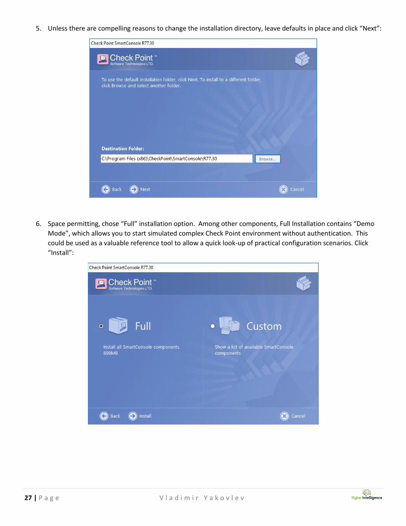
5. Unless there are compelling reasons to change the installation directory, leave defaults in place and click “Next”:
6. Space permitting, chose “Full” installation option. Among other components, Full Installation contains “Demo
Mode”, which allows you to start simulated complex Check Point environment without authentication. This
could be used as a valuable reference tool to allow a quick look-up of practical configuration scenarios. Click
“Install”:

28 | P a g e V l a d i m i r Y a k o v l e v
7. Observe installation progress and, once completed click “Finish”.
8. Select “Demo Mode” and click “Login” to verify successful installation and functionality of the SmartConsole
components:

29 | P a g e V l a d i m i r Y a k o v l e v
9. If you are seeing SmartDashboard screen similar to one shown below, your SmartConsole is working normally.
10. Exit “Demo Mode” by closing the application.
30 | P a g e V l a d i m i r Y a k o v l e v
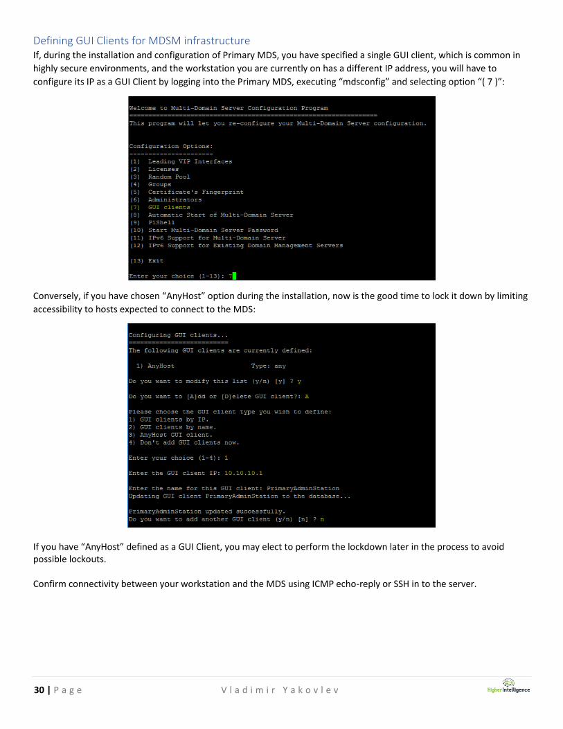
Defining GUI Clients for MDSM infrastructure If, during the installation and configuration of Primary MDS, you have specified a single GUI client, which is common in
highly secure environments, and the workstation you are currently on has a different IP address, you will have to
configure its IP as a GUI Client by logging into the Primary MDS, executing “mdsconfig” and selecting option “( 7 )”:
Conversely, if you have chosen “AnyHost” option during the installation, now is the good time to lock it down by limiting
accessibility to hosts expected to connect to the MDS:
If you have “AnyHost” defined as a GUI Client, you may elect to perform the lockdown later in the process to avoid possible lockouts. Confirm connectivity between your workstation and the MDS using ICMP echo-reply or SSH in to the server.

31 | P a g e V l a d i m i r Y a k o v l e v
Once routing and connectivity are verified, start “SmartDomain Manager R77.30” from “Check Point SmartConsole R77.30” application group. Once logon window opens, enter user name and password you have configured for the administrator during initial installation and configuration process, IP address of the Primary MDS and, if required, a session description and click “Login”:
1. 2. At this point you should verify the validity of the MDS Certificate’s fingerprint. To do so open parallel SSH session, logon to the MDS and execute “mdsconfig”. When prompted with menu options, chose “( 5 ) Certificate’s Fingerprint” and you shall see it displayed:
Verify that the fingerprints are matching, click “Approve” in the SmartDomain Manager window and chose “n” in the mdsconfig prompt, unless you would like to save the fingerprint to a file for future references. You are now logged on the SmartDomain Manager:
32 | P a g e V l a d i m i r Y a k o v l e v
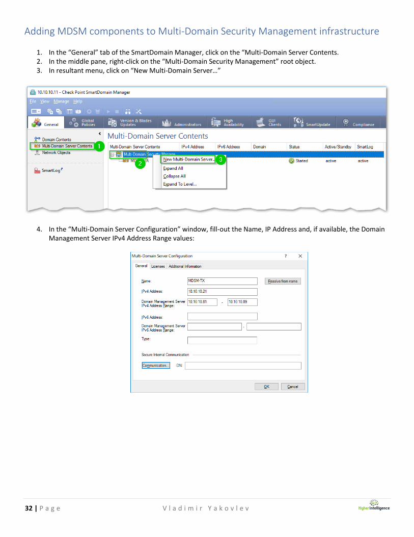
Adding MDSM components to Multi-Domain Security Management infrastructure
1. In the “General” tab of the SmartDomain Manager, click on the “Multi-Domain Server Contents. 2. In the middle pane, right-click on the “Multi-Domain Security Management” root object. 3. In resultant menu, click on “New Multi-Domain Server…”
4. In the “Multi-Domain Server Configuration” window, fill-out the Name, IP Address and, if available, the Domain Management Server IPv4 Address Range values:
33 | P a g e V l a d i m i r Y a k o v l e v
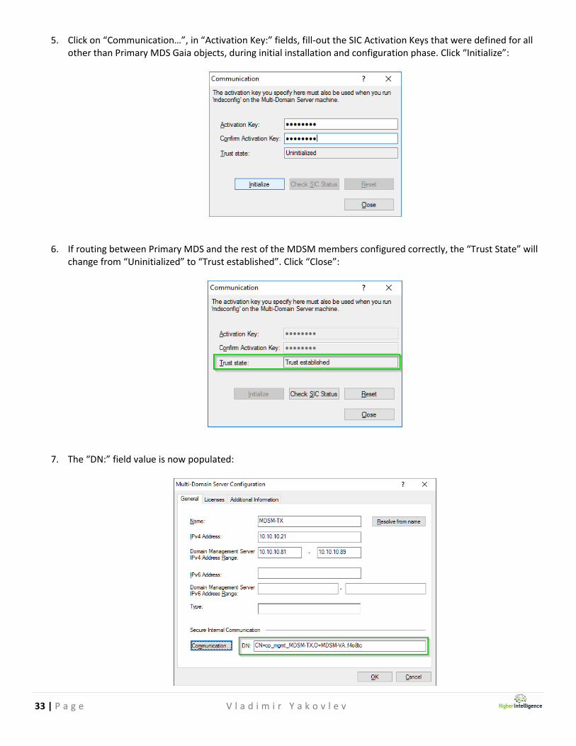
5. Click on “Communication…”, in “Activation Key:” fields, fill-out the SIC Activation Keys that were defined for all other than Primary MDS Gaia objects, during initial installation and configuration phase. Click “Initialize”:
6. If routing between Primary MDS and the rest of the MDSM members configured correctly, the “Trust State” will change from “Uninitialized” to “Trust established”. Click “Close”:
7. The “DN:” field value is now populated:
34 | P a g e V l a d i m i r Y a k o v l e v
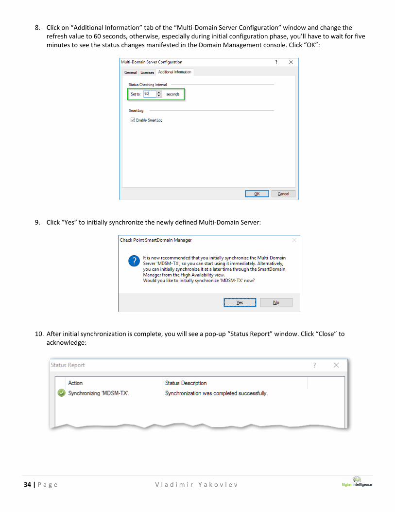
8. Click on “Additional Information” tab of the “Multi-Domain Server Configuration” window and change the refresh value to 60 seconds, otherwise, especially during initial configuration phase, you’ll have to wait for five minutes to see the status changes manifested in the Domain Management console. Click “OK”:
9. Click “Yes” to initially synchronize the newly defined Multi-Domain Server:
10. After initial synchronization is complete, you will see a pop-up “Status Report” window. Click “Close” to acknowledge:

35 | P a g e V l a d i m i r Y a k o v l e v
11. Your Smart Domain Management console now displays two Domain Management servers as “Started” and “active”:
12. Repeat steps from [1] to [11] adding the rest of the Multi-Domain Servers and Multi-Domain Log Servers to your topology.
13. Repeat steps [7] and [8] for you Primary MDS and the rest of the servers you have added to your topology to improve status monitoring refresh rate. Keep at it until all your Multi-Domain members are “Started” and “active”:
Note that the Multi-Domain Log Servers will be recognized as such and are represented by different icons.

36 | P a g e V l a d i m i r Y a k o v l e v
Creating Domains Note: If you are building new domain from a scratch, continue reading this page. If you are importing objects and rules exported from existing domain, go to Page # 67
1. In the SmartDomain Manager’s “General” tab, click on the “Domain Contents” 2. Right-click on “Multi-Domain Security Management”. 3. Click on “New Domain…”.
4. Leave the “Simplified Domain Creation (recommended) radio-button selection in pace and click “Next”:

37 | P a g e V l a d i m i r Y a k o v l e v
5. Enter your new domain’s name and click “Next”:
6. In the “Domain Assigned GUI Clients” window, select either “AnyHost” object or create a “New GUI Client”, select it in the “Not Assigned:” section on the left and click “Add >” to move it into “Assigned:” section on the right. Click “Next”:
38 | P a g e V l a d i m i r Y a k o v l e v
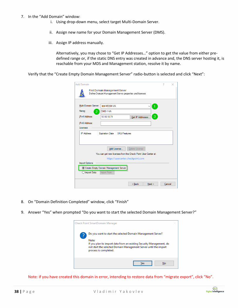
7. In the “Add Domain” window: i. Using drop-down menu, select target Multi-Domain Server.
ii. Assign new name for your Domain Management Server (DMS).
iii. Assign IP address manually.
Alternatively, you may chose to “Get IP Addresses…” option to get the value from either pre-defined range or, if the static DNS entry was created in advance and, the DNS server hosting it, is reachable from your MDS and Management station, resolve it by name.
Verify that the “Create Empty Domain Management Server” radio-button is selected and click “Next”:
8. On “Domain Definition Completed” window, click “Finish” 9. Answer “Yes” when prompted “Do you want to start the selected Domain Management Server?”
Note: if you have created this domain in error, intending to restore data from “migrate export”, click “No”.

39 | P a g e V l a d i m i r Y a k o v l e v
10. After a brief pause, your new domain is created. Click [+] to the left of the new domain name and in expanded view see the newly created Doman Management Server. After a while, the hour glass icon in the “Status” of new DMS will change to the green “Started” indicator:

40 | P a g e V l a d i m i r Y a k o v l e v
Connecting to Domain Management Server
1. From SmartDomain Manager’s “General/Domain Contents” view, expand the domain by clicking on [+]. 2. Right-click on the DMS object. 3. Click on “Launch Application”. 4. Click on “Smart Dashboard”.
5. During first time logon, you will be prompted with verification of MDS’ certificate’s fingerprint. Since this connection is being launched from the parent MDS window, it is safe to click “Approve”.
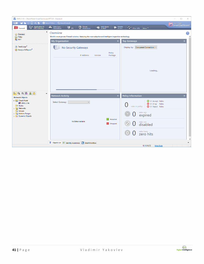
6. Smart Dashboard opens. Expand the “Check Point” folder in the “Network Objects” to see the DMS object:
41 | P a g e V l a d i m i r Y a k o v l e v

42 | P a g e V l a d i m i r Y a k o v l e v
7. Double click the DMS object to open its properties. Click on “Get” next to “Unknown OS”:
8. When you see the notification that the OS version was changed to Gaia, click “Yes”:

43 | P a g e V l a d i m i r Y a k o v l e v
9. Click “OK”:
10. Now save the configuration by either clicking on “Save” icon at the top-left section of the menu bar, or by pressing “Ctrl + S”. If you attempt to exit a dashboard without saving configuration changes, you will see following prompt. Click “Yes” to save changes and exit SmartDashboard.

44 | P a g e V l a d i m i r Y a k o v l e v
Configuring Domain Management High Availability
1. In SmartDomain Manager, click to select domain. 2. Right-click on selected domain. 3. Click on “Add Domain Management Server…”
4. Select target MDS, enter the name of the DMS you are creating and either assign the IP address manually, or
chose to “Get IP Addresses…” option if you have range or static DNS entry already defined. Click “OK”:
45 | P a g e V l a d i m i r Y a k o v l e v
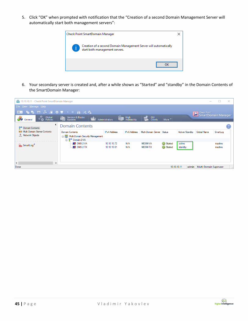
5. Click “OK” when prompted with notification that the “Creation of a second Domain Management Server will automatically start both management servers”:
6. Your secondary server is created and, after a while shown as “Started” and “standby” in the Domain Contents of the SmartDomain Manager:

46 | P a g e V l a d i m i r Y a k o v l e v
Configuring Domain Log Servers
1. In the SmartDomain Manager’s “Domain Contents” window pane, right click the domain object and click “Add Domain Log Server…”:
2. Select Multi-Domain Log Server where your Domain Log Server will reside from the drop-down box. Assign name to the Domain Log Server and either assign IP address manually, or chose “Get IP Addresses…” option to get IP from the pre-assigned range or pre-defined static DNS entry:

47 | P a g e V l a d i m i r Y a k o v l e v
3. Note the instructions for the installation of the database requirements. We will have to follow those after all of our Domain Log Servers are defined:
4. Proceed with creation of the additional Domain Log Servers by repeating previously described procedures:
5. Same notification about the installation of database requirements will be displayed after each new log server object is defined:

48 | P a g e V l a d i m i r Y a k o v l e v
6. Select primary DMS for this domain, right-click and click on “Launch SmartDashboard”.
7. Once SmartDashboard opens, expand “Check Point” object folder.
8. Double-click on each newly created object and perform “Get” to update OS version from Unknown to Gaia and
close object’s properties window.
9. Click on the icon located in the top-left corner, click on “Policy” and “Install Database”:
49 | P a g e V l a d i m i r Y a k o v l e v
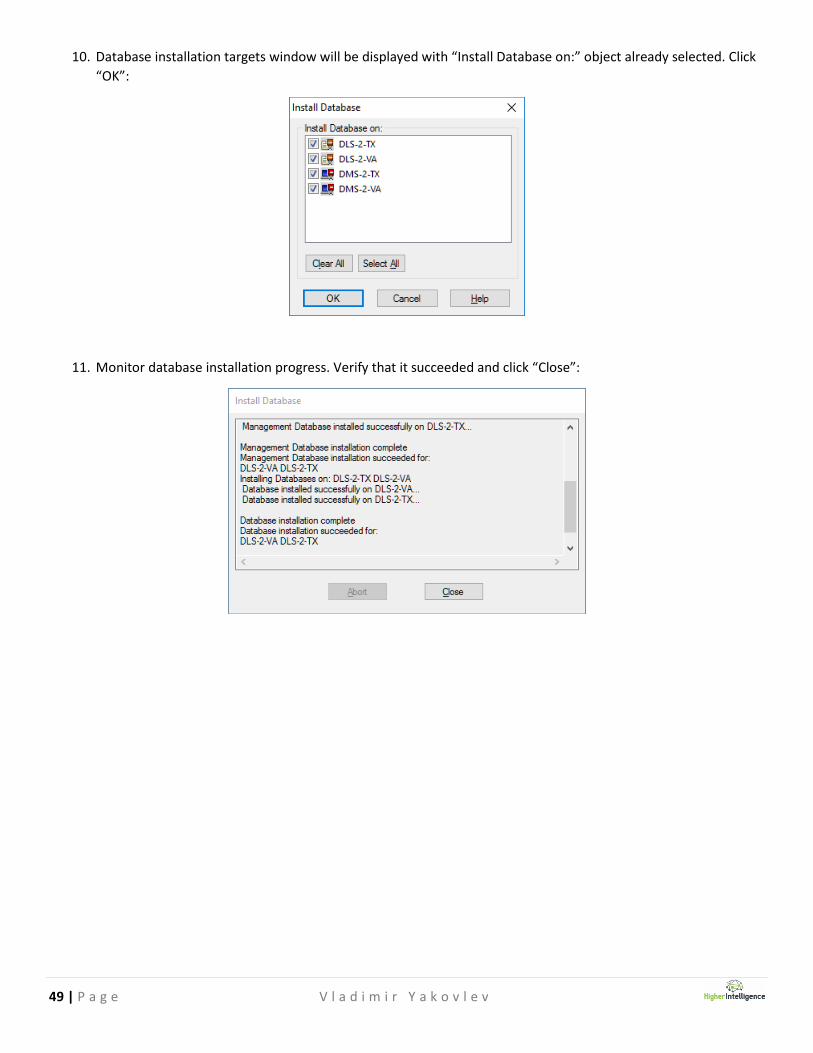
10. Database installation targets window will be displayed with “Install Database on:” object already selected. Click
“OK”:
11. Monitor database installation progress. Verify that it succeeded and click “Close”:

50 | P a g e V l a d i m i r Y a k o v l e v
Enabling SmartLog in the domain contents
1. In the SmartDashboard, expand Check Point object folder and double-click on one of the previously defined log
servers:
2. In the Check Point Host window, click on “Logs” item in the properties tree on the left and check the box “Enable SmartLog”. Click “OK”:

51 | P a g e V l a d i m i r Y a k o v l e v
3. Go to SmartDomain, see SmartLog being shown as “active”:
4. Repeat the same procedure for other log server object that you would like to enable the SmartLog on.
5. Install database.
Now, both Domain Log Servers have SmartLog activated.

52 | P a g e V l a d i m i r Y a k o v l e v
Configuring VSX HA Clusters
1. Open SmartDashboard for the Domain Management Server that will be managing your VSX Cluster(s).
2. In the “Network Objects”, right-click on “Check Point” folder, click on “VSX” and click on “Cluster…”:
3. If you are prompted with request to save current configuration before proceeding, click “Yes”:

53 | P a g e V l a d i m i r Y a k o v l e v
4. Enter the new cluster’s name, virtual IP address of the cluster object, and, in the drop-down menu, chose “Check Point SecurePlatform (ClusterXL)” option and click “Next”:
5. Unless you have a compelling reason to do otherwise, choose the “Custom Configuration” option on the bottom, as it allows for maximum flexibility and click “Next”:

54 | P a g e V l a d i m i r Y a k o v l e v
6. Click “Add” to populate “VSX Cluster Members” table:
7. Fill-out name of the node, its’ management interface IP address, enter and verify SIC “Activation Key” that was defined during original installation and configuration of the VSX Cluster Candidate appliance and click “Initialize”:
55 | P a g e V l a d i m i r Y a k o v l e v
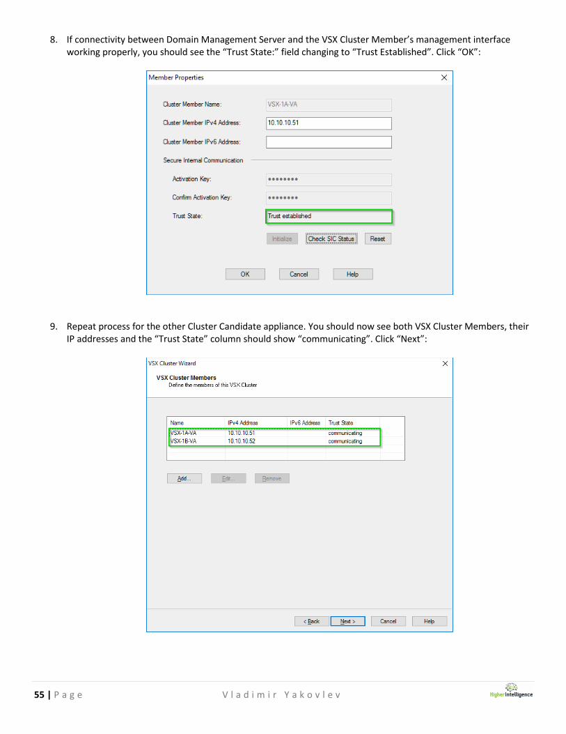
8. If connectivity between Domain Management Server and the VSX Cluster Member’s management interface working properly, you should see the “Trust State:” field changing to “Trust Established”. Click “OK”:
9. Repeat process for the other Cluster Candidate appliance. You should now see both VSX Cluster Members, their IP addresses and the “Trust State” column should show “communicating”. Click “Next”:

56 | P a g e V l a d i m i r Y a k o v l e v
10. Choose the interfaces that are going to carry multi-VLAN traffic and become trunk members. Unless there are compelling reasons to do so, leave Management and Sync interfaces as dedicated hardware or bonds. Click “Next”:
11. From the drop-down menu, chose interface for the Sync Network. Assign IPs and subnet masks. Click “Next”:

57 | P a g e V l a d i m i r Y a k o v l e v
12. Note the warning about making a management interface to be shared. If you have elected to keep it dedicated, skip this window by clicking “Next”:
13. Now is the good time to define the default security policy for the management access to the VSX Cluster object
itself. Note that this policy will not be applied to any of the virtual systems hosted by this cluster. Best practice,
at this point, is to use “ New Source Object…“ to define Management Hosts and/or networks that should be
permitted to access the cluster object with protocols listed, create a simple group object, add management
hosts and networks to it and select it in via drop-down menu in each rule. Do not forget to enable select rules
by selecting check-box options on the left. Click “Next” when you are done:

58 | P a g e V l a d i m i r Y a k o v l e v
14. If you are getting a warning about Service(s) with sources set to ‘Any’, verify that you rpolicy configured
correctly- as you can see, even if the rules with ‘Any’ in sources are not enabled, you are still being prompted
with the warning. If the policy is correctly defined, click “Yes”.
Click “Finish” to finalize VSX Cluster Configuration.
15. Finalization process takes some time and, when completed, you should see the Cluster Creation Summary:

59 | P a g e V l a d i m i r Y a k o v l e v
16. Click “Close”. You should now see the VSX Cluster object in the Check Point folder of the Network Objects list:
17. Double click the newly created VSX Cluster object and click on the “Cluster Members” item on the left. Examine
the “internal communication network properties. Do not change its value unless warranted:

60 | P a g e V l a d i m i r Y a k o v l e v
18. Press “Ctrl + S” to save changed settings on your SmartDashboard. Install Database by pressing “Alt + P”, “d” and
clicking “OK” o the popup window with database Installation targets:
19. Verify successful installation by scrolling through the report and click “Close”:
20. Open “SmartView Monitor” by pressing “Ctrl + Shift + m” and verify normal cluster members’ operation:

61 | P a g e V l a d i m i r Y a k o v l e v
21. If you need to see the policy applied to the VSX Cluster, return to the SmartDashboard and press “Alt + F” and
“O”. In the Open Policy Package window, you will see the policy with the name in the format:
<VSX Cluster Name>_VSX”. Select it and click “Open”:
22. You should see and can modify and Install VSX Cluster policy from here:

62 | P a g e V l a d i m i r Y a k o v l e v
Configuring Virtual Systems
1. From SmartDashboard, Network Objects tree, right click “Check Point”, click on “VSX” and click on “Virtual
System…”
2. Assign new Virtual System its name and choose the VSX Gateway / Cluster it will reside on:

63 | P a g e V l a d i m i r Y a k o v l e v
3. Click “Add” under the “Interfaces” section:
4. Select physical interfaces or bonds, specify VLANs, if present, assign IP addresses and select checkbox
“Propagate route to adjacent Virtual Devices” if required:

64 | P a g e V l a d i m i r Y a k o v l e v
5. Once interfaces are defined, “Routes” section will be automatically populated with the connected networks:
6. Click on “Add”, to create Static Route entries. Click on “Add Default Route…” to define its default gateway.
65 | P a g e V l a d i m i r Y a k o v l e v
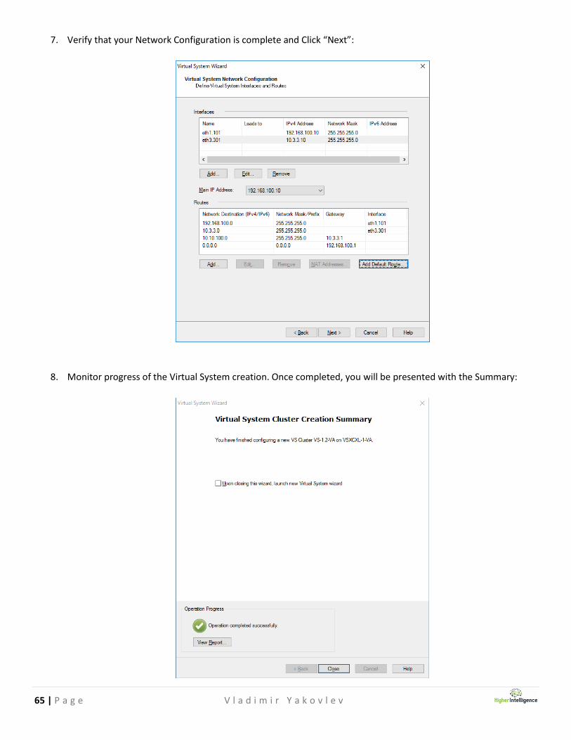
7. Verify that your Network Configuration is complete and Click “Next”:
8. Monitor progress of the Virtual System creation. Once completed, you will be presented with the Summary:

66 | P a g e V l a d i m i r Y a k o v l e v
9. View report to verify and click “Close” twice. You should now see the created VS gateway in Network Objects:
Repeat as necessary to create Virtual Systems nested in their corresponding domains.
67 | P a g e V l a d i m i r Y a k o v l e v
Restoring Domain Management Server content
If the backup, or “migrate export” is performed within same infrastructure, use “migrate import” command to recover
Domain Management Server’s content.
Please note that if any of the Global Objects in MDS were renamed in the interim, the restore may fail. See sk105861 :
https://supportcenter.checkpoint.com/supportcenter/portal?eventSubmit_doGoviewsolutiondetails=&solutionid=sk105
861
You may have to contact Check Point directly to obtain a hotfix referenced in sk105861 to circumvent this issue.
Also, note, that same behavior will manifest itself if you are trying to perform “migrate import” for transferring domains
from old to new infrastructure. If you would like this process to succeed, you must re-create all Global Objects in the
new MDSM infrastructure BEFORE attempting to perform “migrate import”.
Same hotfix, referenced in the sk105861 may be able to alleviate this problem.
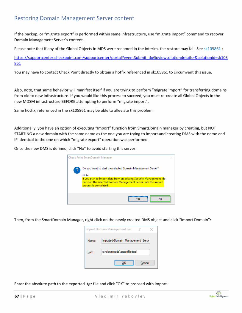
Additionally, you have an option of executing “Import” function from SmartDomain manager by creating, but NOT
STARTING a new domain with the same name as the one you are trying to import and creating DMS with the name and
IP identical to the one on which “migrate export” operation was performed.
Once the new DMS is defined, click “No” to avoid starting this server:
Then, from the SmartDomain Manager, right click on the newly created DMS object and click “Import Domain”:
Enter the absolute path to the exported .tgz file and click “OK” to proceed with import.

68 | P a g e V l a d i m i r Y a k o v l e v
Sanitizing exported DMS data for new environments
A possible intermediate solution for successful import of the objects and, possibly, rules in to the new environment is to:
1. Create a production MDS backup.
2. Import it in to a virtualized instance with the same name, IP address and ample storage space.
3. Start nested DMS instances.
4. Open Global SmartDashboard.
5. Take a note of the Global Policies and un-assign them from domains.
6. Take a note of Globally Defined objects.
7. Delete all globally defined objects, tracing dependencies, when prompted, and sanitizing the rules by either
removing them, or replacing the global objects with the local objects.
8. If the imported DMS will be targeting Virtual Systems that have different IP Schema, make the changes to VS’.
9. If the concern is primarily recreation of the objects, delete all rules from the DMS’ policies and blades.
10. Install the database.
11. Perform “migrate export” of the sanitized DMS.
12. Transfer resultant file to the target DMS for import.

69 | P a g e V l a d i m i r Y a k o v l e v
Configuring SNMP monitoring for MDSM infrastructure components
Depending on your requirements and the desired security state of your infrastructure, you may choose to use SNMP v2
or v3. SNMP v3 is much preferable as it, when used with some products allows for per-VS queries.
To facilitate mass-deployment of SNMP on all your Check Point devices for monitoring: hardware, link state changes,
authorization errors reboots and configuration changes, use following script, modifying highlighted entries with those of
your own:
Note: there is presently an issue with Solar Winds products preventing monitoring of individual VS’, see sk111653:
https://supportcenter.checkpoint.com/supportcenter/portal?eventSubmit_doGoviewsolutiondetails=&solutionid=sk111
653
set snmp mode default
set snmp agent on
set snmp community piggybank read-only
set snmp agent-version v3-Only
add snmp traps receiver 10.10.10.1 community piggybank version v2
add snmp usm user piggybank security-level authPriv auth-pass-phrase Snmpp@ssw0rd privacy-pass-phrase Snmpp@ssw0rd privacy-protocol AES
set snmp traps trap authorizationError enable
set snmp traps trap coldStart enable
set snmp traps trap configurationChange enable
set snmp traps trap configurationSave enable
set snmp traps trap fanFailure enable
set snmp traps trap highVoltage enable
set snmp traps trap linkUpLinkDown enable
set snmp traps trap lowDiskSpace enable
set snmp traps trap lowVoltage enable
set snmp traps trap overTemperature enable
set snmp traps trap powerSupplyFailure enable
set snmp traps trap raidVolumeState enable
set snmp traps polling-frequency 20
set snmp traps trap-user piggybank
set snmp contact "the Dude(s)"
set snmp location "VA Datacenter, Rack 3.10"
set snmp agent off
set snmp agent on
save config
70 | P a g e V l a d i m i r Y a k o v l e v
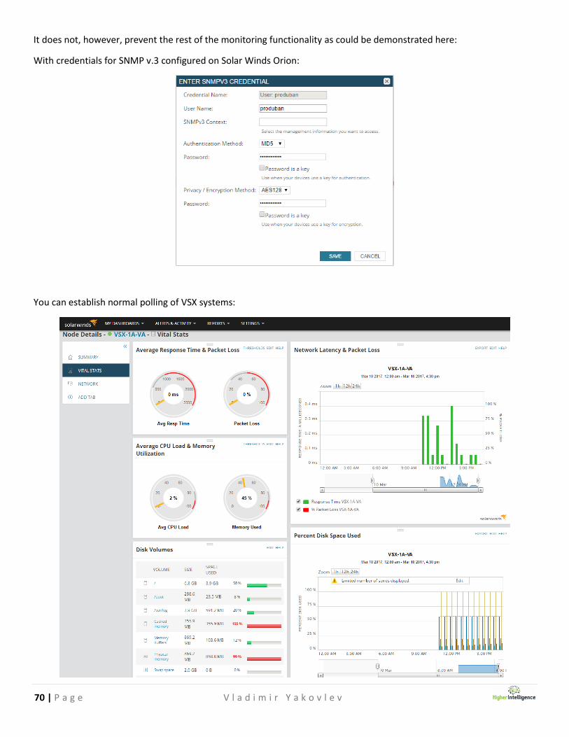
It does not, however, prevent the rest of the monitoring functionality as could be demonstrated here:
With credentials for SNMP v.3 configured on Solar Winds Orion:
You can establish normal polling of VSX systems:
71 | P a g e V l a d i m i r Y a k o v l e v
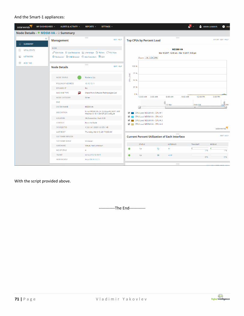
And the Smart-1 appliances:
With the script provided above.
------------The End------------

72 | P a g e V l a d i m i r Y a k o v l e v
Notes