Embed Size (px)
Citation preview
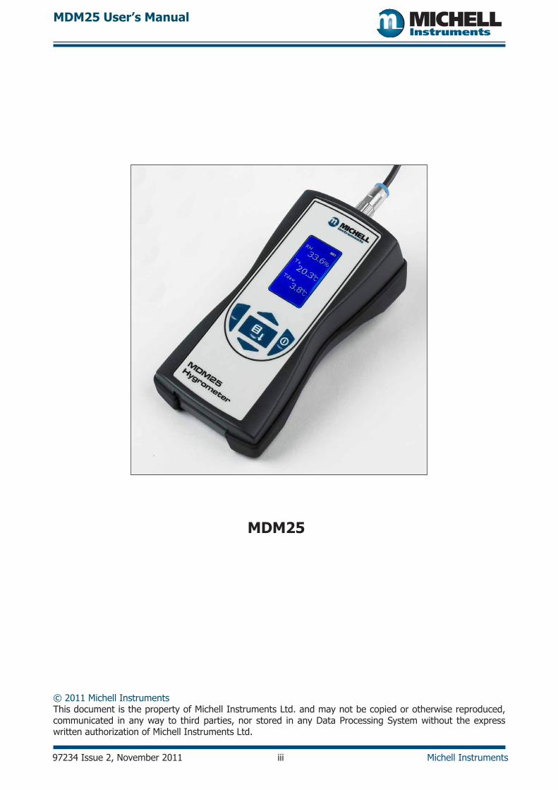
MDM25Hygrometer
User’s Manual
97234 Issue 2, November 2011 Michell Instruments
RH
Ta
Abs H
53.1%
21.0°C
9.7g:M
3
MDM25Hygrometer

Inside front cover (blank)
MDM25 User’s Manual
97234 Issue 2, November 2011 iii Michell Instruments
© 2011 Michell Instruments This document is the property of Michell Instruments Ltd. and may not be copied or otherwise reproduced, communicated in any way to third parties, nor stored in any Data Processing System without the express written authorization of Michell Instruments Ltd.
MDM25
MDM25 User’s Manual
97234 Issue 2, November 2011 iv Michell Instruments
Contents
Safety .............................................................................................................................................. vElectrical Safety ......................................................................................................................... vPressure Safety ......................................................................................................................... vToxic Materials .......................................................................................................................... vRepair and Maintenance............................................................................................................. vCalibration ................................................................................................................................ vSafety Conformity ...................................................................................................................... v
Abbreviations ....................................................................................................................................viWarnings ..........................................................................................................................................viRecycling Policy .................................................................................................................................viWEEE And RoHS Compliance .............................................................................................................viiCalibration Facilities ..........................................................................................................................viiManufacturing Quality .......................................................................................................................viiWarranty ........................................................................................................................................ viiiReturn Policy ................................................................................................................................... viii
1 INTRoduCTIoN ........................................................................................................................ 1
2 dESCRIPTIoN ........................................................................................................................... 22.1 Controls and Indicators ................................................................................................... 22.2 Instrument display ......................................................................................................... 32.3 display units .................................................................................................................. 42.4 display Settings .............................................................................................................. 42.5 device Settings ............................................................................................................... 42.6 About ............................................................................................................................ 4
3 SET-uP ..................................................................................................................................... 53.1 unpacking the Instrument ............................................................................................... 53.2 MdM25 Accessories ........................................................................................................ 53.3 Battery Requirements ...................................................................................................... 63.4 Fitting the Batteries ........................................................................................................ 63.5 Mounting and Connecting the Probe ................................................................................. 7
4 oPERATIoN .............................................................................................................................. 84.1 Preparation for operation ................................................................................................ 84.2 overall Menu Structure .................................................................................................... 84.2.1 display Settings .......................................................................................................... 94.2.2 device Settings ..........................................................................................................104.2.3 About........................................................................................................................11
5 gENERAl oPERATIoNAl guIdElINES ......................................................................................125.1 Probe Calibration ...........................................................................................................125.2 Maintenance ..................................................................................................................125.2.1 Cleaning ....................................................................................................................125.2.2 Probe Replacement ....................................................................................................125.2.3 Batteries ...................................................................................................................12
MDM25 User’s Manual
Michell Instruments v 97234 Issue 2, November 2011
Appendices
Appendix A Technical Specifications ......................................................................................... 14
Appendix B List of Worldwide Michell Instruments’ Offices ......................................................... 16
Figures
Figure 2.1 Controls and Indicators ..........................................................................................2Figure 2.2 display ..................................................................................................................3
Figure 3.1 Battery Compartment location ................................................................................6Figure 3.2 Probe Connections .................................................................................................7
Figure 4.1 Main Menu Structure ..............................................................................................8Figure 4.2 display Settings Menu ............................................................................................9Figure 4.3 device Settings Menu ...........................................................................................10Figure 4.4 About Menu .........................................................................................................11
Tables
Table 2.1 Function Keys .........................................................................................................2Table 2.2 display Elements ....................................................................................................3Table 2.3 unit descriptions.....................................................................................................4
MDM25 User’s Manual
97234 Issue 2, November 2011 vi Michell Instruments
Safety
The manufacturer has designed this equipment to be safe when operated using the procedures detailed in this manual. The user must not use this equipment for any other purpose than that stated. do not apply values greater than the maximum value stated.
This manual contains operating and safety instructions, which must be followed to ensure the safe operation and to maintain the equipment in a safe condition. The safety instructions are either warnings or cautions issued to protect the user and the equipment from injury or damage. use competent personnel using good engineering practice for all procedures in this Manual.
Electrical Safety
The instrument is designed to be completely safe when used with options and accessories supplied by the manufacturer for use with the instrument.
Pressure Safety
This product is not suitable for use at pressures greater than atmospheric.
Toxic Materials
The use of hazardous materials in the construction of this instrument has been minimized. during normal operation it is not possible for the user to come into contact with any hazardous substance which might be employed in the construction of the instrument. Care should, however, be exercised during maintenance and the disposal of certain parts.
Repair and Maintenance
The instrument must be maintained either by the manufacturer or an accredited service agent. Refer to Appendix B for details of Michell Instruments’ worldwide offices contact information.
Calibration
An annual calibration is recommended for the RH probe. This should be returned to the manufacturer, Michell Instruments, or one of their accredited service agents for re-calibration.
Safety Conformity
This product meets the essential protection requirements of the relevant Eu directives. Further details of applied standards may be found in the product specification.
MDM25 User’s Manual
Michell Instruments vii 97234 Issue 2, November 2011
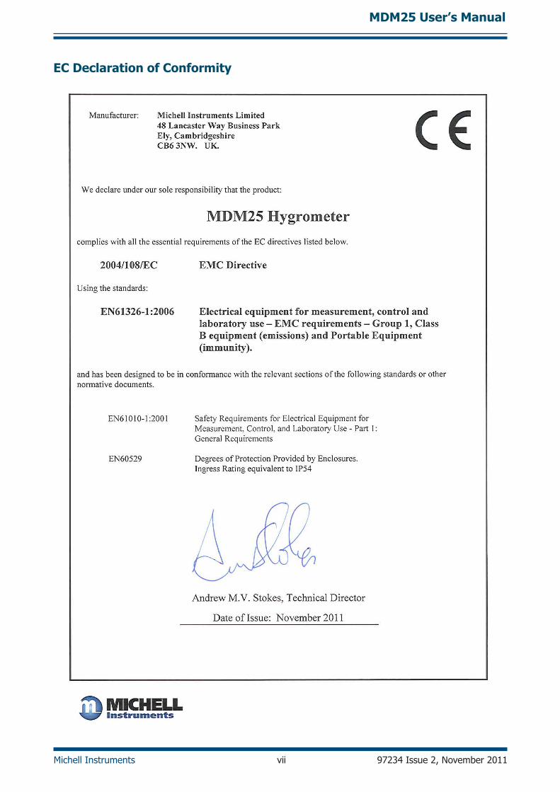
EC Declaration of Conformity
MDM25 User’s Manual
97234 Issue 2, November 2011 viii Michell Instruments
Abbreviations
The following abbreviations are used in this Manual:
Abs H absolute humidity
ºC degrees Celsius
ºF degrees Fahrenheit
lCd liquid crystal display
g grams
g/m3 grams per cubic meter
lb pound
mm millimeters
oz ounce
RH relative humidity
sec second(s)
T temperature
Ta ambient temperature
Td dew point
Tw wet bulb temperature
V Volts
% percentage
Warnings
The following general warnings listed below are applicable to this instrument. They are repeated in the text in the appropriate locations.
Where this hazard warning symbol appears in the following sections it is used to indicate areas where potentially
hazardous operations need to be carried out.
Recycling Policy Michell Instruments is concerned with the protection of the environment. It is our commitment to reduce and eliminate from our operations, wherever possible, the use of substances which may be harmful to the environment. Similarly, we are increasingly using recyclable and/or recycled material in our business and products wherever it is practical to do so.
The product that you have purchased may contain recyclable and/or recycled parts and we will be happy to provide you with information on these components if required.
MDM25 User’s Manual
Michell Instruments ix 97234 Issue 2, November 2011
WEEE And RoHS Compliance
The Waste Electronic and Electrical Equipment (WEEE) directive, and the Restriction of Hazardous Substances (RoHS) directive place rules upon European manufacturers of electrical and electronic equipment. The directives’ aim is to reduce the impact that electronic devices have on the environment.
Michell products are currently exempt from the RoHS directive, however all future products will be developed entirely using compliant materials. Furthermore, Michell is taking active steps to remove non-compliant materials and components from existing products wherever possible.
Michell is in full compliance with the WEEE directive (Registration No. WEE/JB0235YW). Customers may be required to return certain instruments for treatment at the end of their working life.
June 2010
Calibration Facilities
Michell Instruments’ calibration facilities are among the most sophisticated in the world and have been recognized for their excellence.
Traceability to the National Physical laboratory (NPl) uK is achieved through our uKAS Accreditation (Number 0179). This covers dew point over the range -90 to +90ºC (-130 to +194ºF) and also Relative Humidity.
dew-point calibrations are also traceable to the National Institute for Standards & Technology (NIST) uSA over the range -75 to +20ºC (-103 to +68ºF).
NOTE: Standard traceable calibration certificates for instruments and sensors are not issued under our UKAS accreditation. UKAS certificates are usually to special order and are clearly identified.
Manufacturing Quality
Michell Instruments is registered with the British Standards Institute for Quality Assurance to:
BS EN ISo 9001: 2008
Rigorous procedures are performed at every stage of production to ensure that the materials of construction, manufacturing, calibration and final test procedures meet the requirements laid down by our BSI approved Quality System.
Please contact Michell Instruments if the product does not arrive in perfect working order.
MDM25 User’s Manual
97234 Issue 2, November 2011 x Michell Instruments
Warranty
unless otherwise agreed, the Supplier warrants that, as from the date of delivery for a period of 12 months the goods and all their component parts, where applicable, are free from any defects in design, workmanship, construction or materials.
The Supplier warrants that the services undertaken shall be performed using reasonable skill and care, and of a quality conforming to generally accepted industry standards and practices.
Except as expressly stated, all warranties, whether express or implied, by operation of law or otherwise, are hereby excluded in relation to the goods and services to be provided by the Supplier.
All warranty services are provided on a return to base basis. Any transportation costs for the return of a warranty claim shall reside with the Customer.
Return Policy
If a Michell Instruments’ product malfunctions within the warranty period, the following procedure must be completed:
1. Notify a Michell Instruments’ distributor, giving full details of the problem, the model variant and the serial number of the product.
2. If the nature of the problem indicates the need for factory service then the instrument should be returned to Michell Instruments, carriage prepaid, preferably in the original packaging, with a full description of the fault and the customer contact information.
3. upon receipt, Michell Instruments will evaluate the product to determine the cause of the malfunction. Then, one of the following courses of action will be taken:
• If the fault is covered under the terms of the warranty, the instrument will be repaired at no cost to the owner and returned.
• If Michell Instruments determines that the fault is not covered under the terms of the warranty, or if the warranty has expired, an estimate for the cost of the repairs, at standard rates, will be provided. upon receipt of the owner’s approval to proceed, the product will be repaired and returned.
MDM25 User’s Manual
Michell Instruments 1 97234 Issue 2, November 2011
1 InTRoDUCTIon
The MdM25 is a battery operated, hand-held hygrometer.
Available with a number of different probe configurations and the ability to display relative humidity, temperature, absolute humidity (g/m3), dew point and wet bulb temperature, the MdM25 is suitable for spot-checking humidity in a wide variety of applications.
The hygrometer is contained within a molded ABS housing with a rubber surround for drop protection - sealed to IP54 standards. The rubber surround allows for comfortable hand-held operation and safe transportation of the unit.
It is powered by 3 alkaline ‘AA’ size cells, which are designed to last a minimum of 80 continuous hours between replacement. Continuous battery charge status indication is provided by a battery indicator icon.
A graphical display presents the RH and temperature readings, in addition to a selectable third value, in large format characters.
MDM25 User’s Manual
97234 Issue 2, November 2011 2 Michell Instruments
2 DESCRIPTIon
2.1 Controls and Indicators
The controls and indicators associated with the MdM25 hygrometer are located on the front panel.
The probe connection to the MdM25 hygrometer is made to the top panel, and the battery charger cover is located on the rear of the instrument.
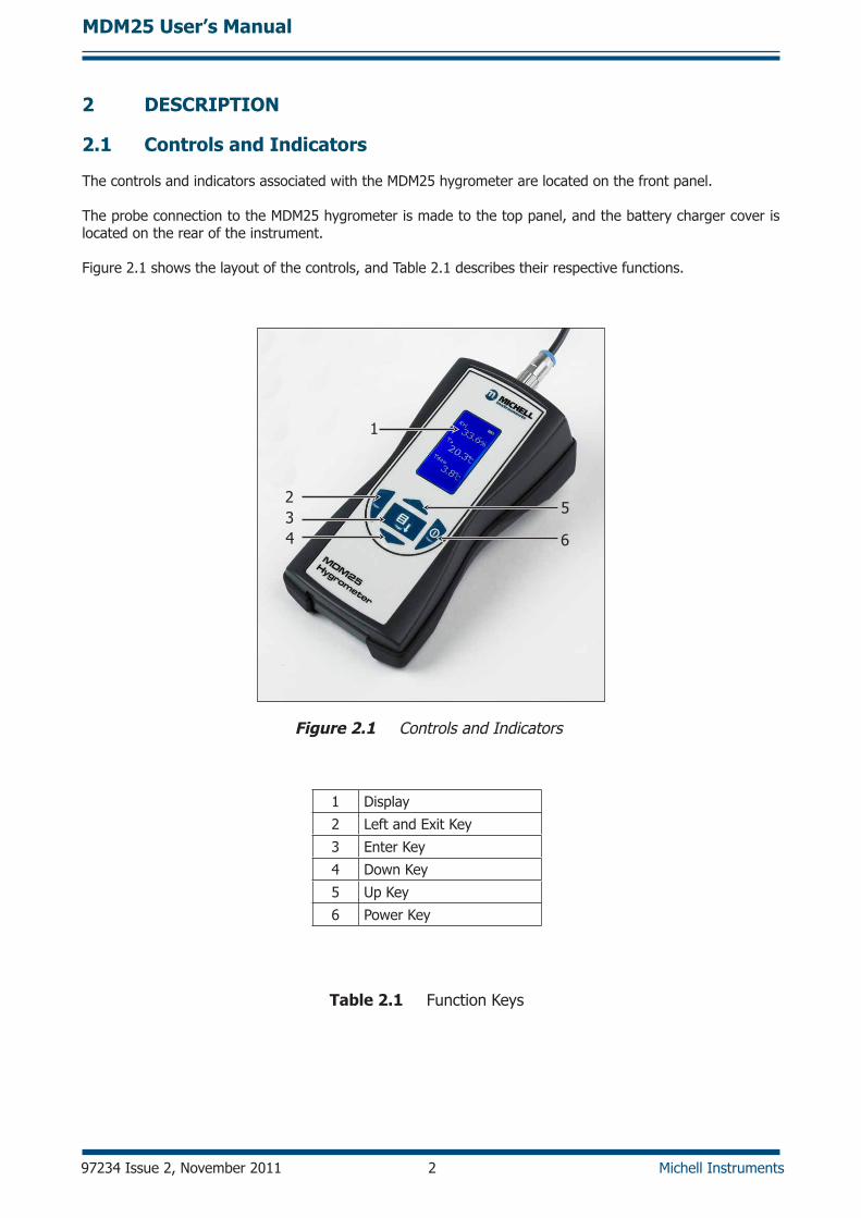
Figure 2.1 shows the layout of the controls, and Table 2.1 describes their respective functions.
1
234
5
6
Figure 2.1 Controls and Indicators
1 display
2 left and Exit Key
3 Enter Key
4 down Key
5 up Key
6 Power Key
Table 2.1 Function Keys
MDM25 User’s Manual
Michell Instruments 3 97234 Issue 2, November 2011
2.2 Instrument Display
RH
Ta
Abs H
53.1%
21.0°C
9.7g:M
3
21
3
4
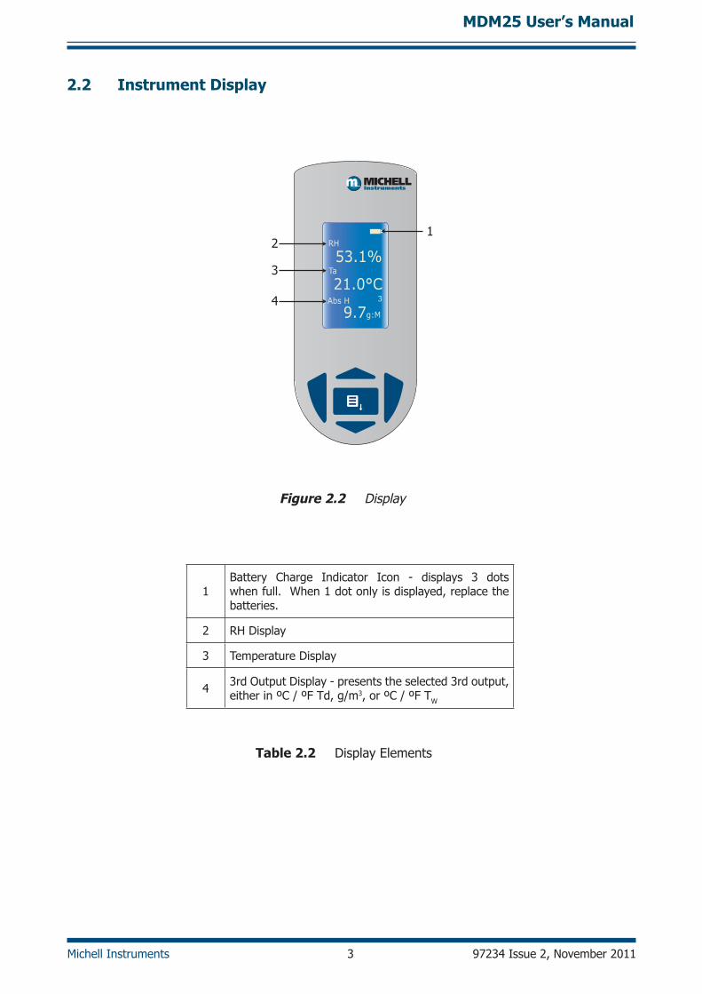
Figure 2.2 display
1Battery Charge Indicator Icon - displays 3 dots when full. When 1 dot only is displayed, replace the batteries.
2 RH display
3 Temperature display
4 3rd output display - presents the selected 3rd output, either in ºC / ºF Td, g/m3, or ºC / ºF TW
Table 2.2 display Elements
MDM25 User’s Manual
97234 Issue 2, November 2011 4 Michell Instruments
2.3 Display Units
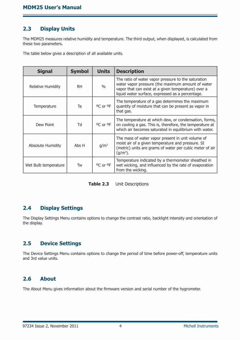
The MdM25 measures relative humidity and temperature. The third output, when displayed, is calculated from these two parameters.
The table below gives a description of all available units.
Signal Symbol Units Description
Relative Humidity RH %
The ratio of water vapor pressure to the saturation water vapor pressure (the maximum amount of water vapor that can exist at a given temperature) over a liquid water surface, expressed as a percentage.
Temperature Ta ºC or ºFThe temperature of a gas determines the maximum quantity of moisture that can be present as vapor in that gas.
dew Point Td ºC or ºFThe temperature at which dew, or condensation, forms, on cooling a gas. This is, therefore, the temperature at which air becomes saturated in equilibrium with water.
Absolute Humidity Abs H g/m3
The mass of water vapor present in unit volume of moist air of a given temperature and pressure. SI (metric) units are grams of water per cubic meter of air (g/m3).
Wet Bulb temperature Tw ºC or ºFTemperature indicated by a thermometer sheathed in wet wicking, and influenced by the rate of evaporation from the wicking.
Table 2.3 unit descriptions
2.4 Display Settings
The display Settings Menu contains options to change the contrast ratio, backlight intensity and orientation of the display.
2.5 Device Settings
The device Settings Menu contains options to change the period of time before power-off, temperature units and 3rd value units.
2.6 About
The About Menu gives information about the firmware version and serial number of the hygrometer.
MDM25 User’s Manual
Michell Instruments 5 97234 Issue 2, November 2011
3 SET-UP
3.1 Unpacking the Instrument
open the box carefully and unpack the contents. Check that the following items are included. Report any shortages immediately.
• MdM25 Hygrometer
• 3 off Alkaline ‘AA’ cells
• user Manual
• RH & Temp Probe (options available)
• Calibration certificate (optional)
3.2 MDM25 Accessories
Filters and Protection Caps (available to fit 12mm (0.47”) or 19mm (0.75”) probes)
• Slotted protection cap, black
• PVDF filter
• Mesh filter
• Flat SS sintered dust filter
• Arrow SS sintered filter 10μm
• Arrow SS sintered filter 20μm
Probes
• Fixed probe
• Standard probe
• Sword type probe
• Remote high temperature probe, 300mm (18”)
• Remote high temperature probe, 500mm (19.6”)
other
• Carrying case
• Batteries (3 ‘AA’ Alkaline cells)
• Control Kit of calibration salts
MDM25 User’s Manual
97234 Issue 2, November 2011 6 Michell Instruments
3.3 Battery Requirements
The MdM25 is supplied with 3 Alkaline ‘AA’ size cells. These non-rechargeable Alkaline cells have a high energy density and long shelf-life.
Do not mix different type of batteries. All three batteries must be of the same type.
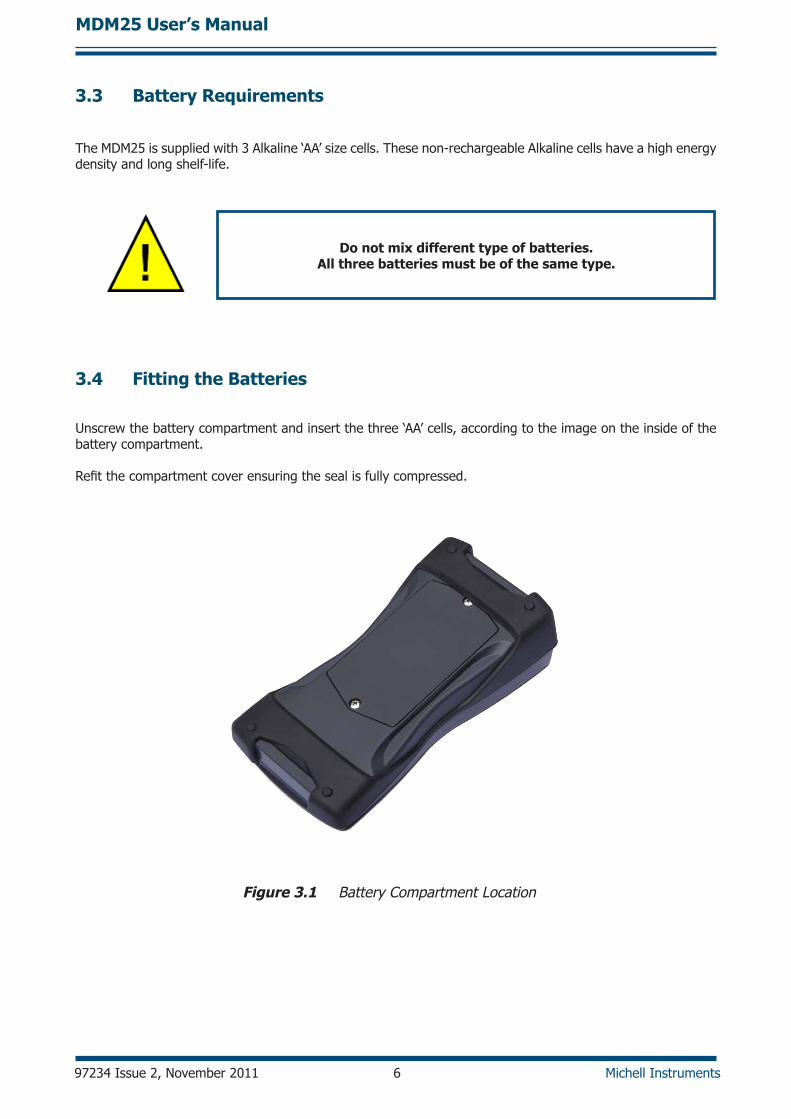
3.4 Fitting the Batteries
unscrew the battery compartment and insert the three ‘AA’ cells, according to the image on the inside of the battery compartment.
Refit the compartment cover ensuring the seal is fully compressed.
Figure 3.1 Battery Compartment location
MDM25 User’s Manual
Michell Instruments 7 97234 Issue 2, November 2011
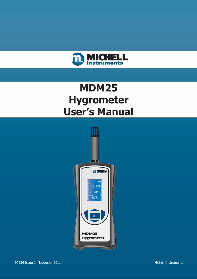
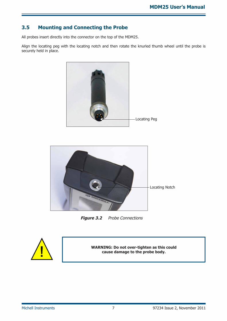
3.5 Mounting and Connecting the Probe
All probes insert directly into the connector on the top of the MdM25.
Align the locating peg with the locating notch and then rotate the knurled thumb wheel until the probe is securely held in place.
locating Peg
locating Notch
Figure 3.2 Probe Connections
WARnInG: Do not over-tighten as this could cause damage to the probe body.
MDM25 User’s Manual
97234 Issue 2, November 2011 8 Michell Instruments
4 oPERATIon
4.1 Preparation for operation
Press the power-on button and observe the readings on the lCd. Some 3rd values may take a few seconds to generate, depending upon the %RH and ambient temperature (Ta).
If using the MdM25 alongside the S503 RH calibrator, adjust the display orientation to allow for the product to be read correctly when upside down.
If there is there is no reading on the screen check the battery orientation. Replace with new batteries if required.
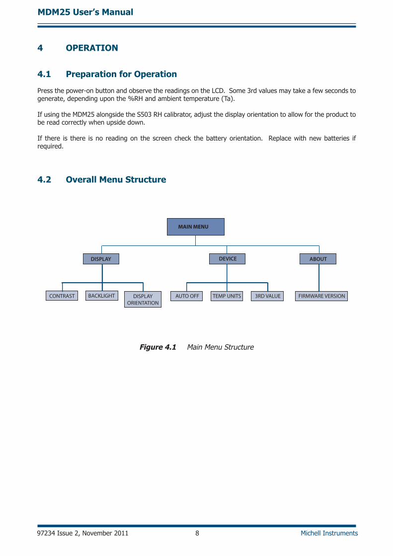
4.2 overall Menu Structure
DISPLAY DEVICE ABOUT
CONTRAST AUTO OFF TEMP UNITS 3RD VALUE FIRMWARE VERSIONBACKLIGHT DISPLAYORIENTATION
MAIN MENU
Figure 4.1 Main Menu Structure
MDM25 User’s Manual
Michell Instruments 9 97234 Issue 2, November 2011
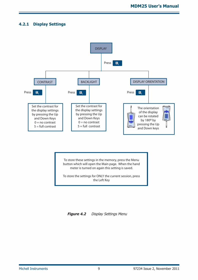
4.2.1 Display Settings
DISPLAY
CONTRAST
Set the contrast for the display settings by pressing the Up
and Down Keys 0 = no contrast5 = full contrast
BACKLIGHT
Set the contrast for the display settings by pressing the Up
and Down Keys0 = no contrast5 = full contrast
DISPLAY ORIENTATION
Press
Press Press Press
Special feature:The display
turns automaticallywhen hand meter
is positionedupside-down
To store these settings in the memory, press the Menu button which will open the Main page. When the hand
meter is turned on again this setting is saved.
To store the settings for ONLY the current session, press the Left Key
The orientation of the display
can be rotated by 180º by
pressing the Up and Down keys
Figure 4.2 display Settings Menu
MDM25 User’s Manual
97234 Issue 2, November 2011 10 Michell Instruments
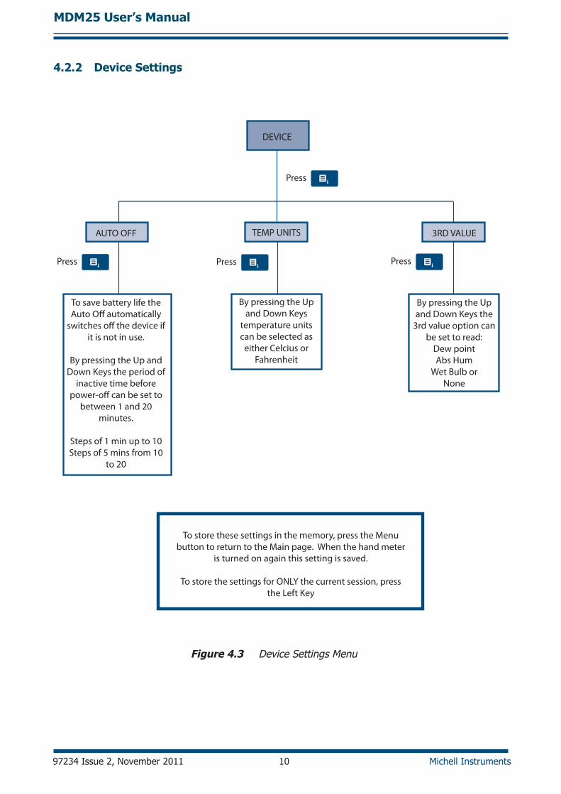
4.2.2 Device Settings
DEVICE
AUTO OFF
To save battery life the Auto O� automatically
switches o� the device if it is not in use.
By pressing the Up and Down Keys the period of
inactive time before power-o� can be set to
between 1 and 20 minutes.
Steps of 1 min up to 10Steps of 5 mins from 10
to 20
TEMP UNITS
By pressing the Up and Down Keys
temperature units can be selected as
either Celcius or Fahrenheit
3RD VALUE
By pressing the Up and Down Keys the
3rd value option can be set to read:
Dew pointAbs Hum
Wet Bulb or None
Press
Press Press Press
To store these settings in the memory, press the Menu button to return to the Main page. When the hand meter
is turned on again this setting is saved.
To store the settings for ONLY the current session, press the Left Key
Figure 4.3 device Settings Menu
MDM25 User’s Manual
Michell Instruments 11 97234 Issue 2, November 2011
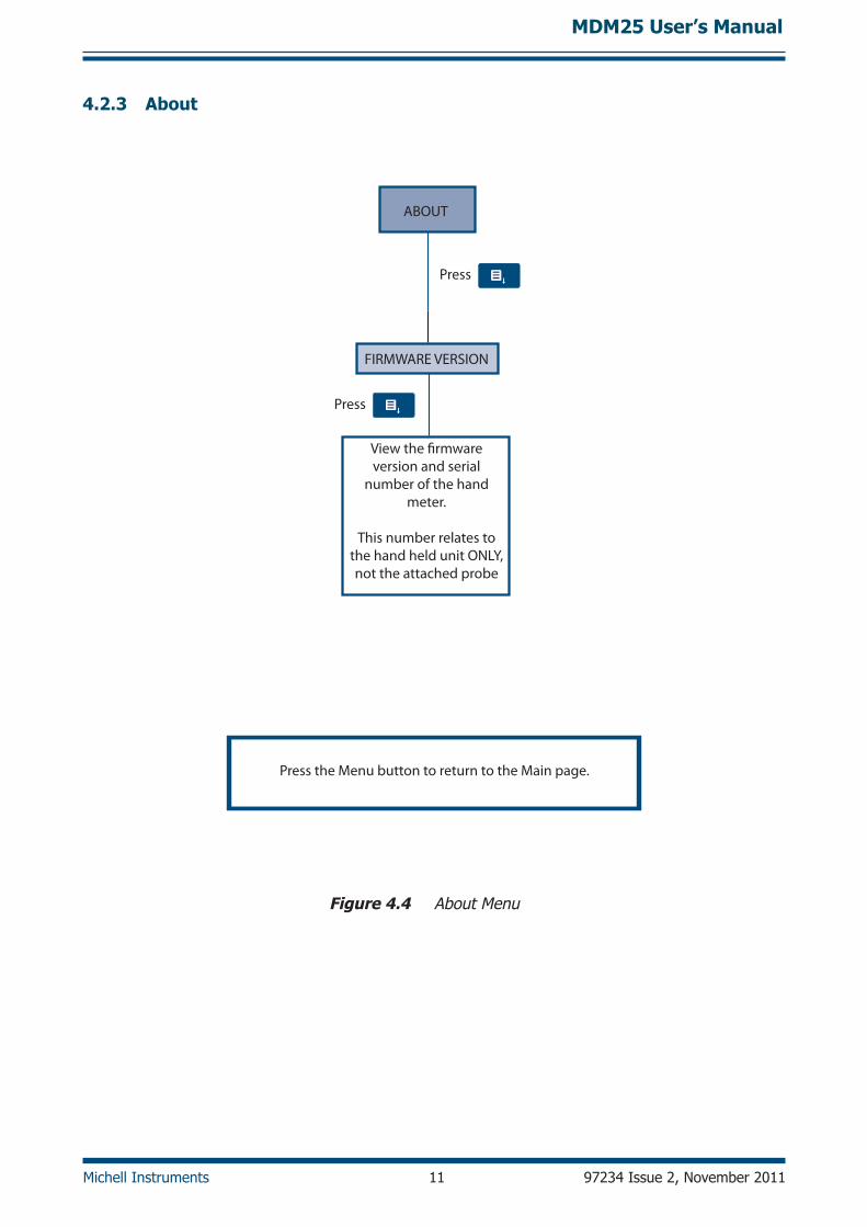
4.2.3 About
ABOUT
FIRMWARE VERSION
View the �rmware version and serial
number of the hand meter.
This number relates to the hand held unit ONLY, not the attached probe
Press
Press
Press the Menu button to return to the Main page.
Figure 4.4 About Menu
MDM25 User’s Manual
97234 Issue 2, November 2011 12 Michell Instruments
5 GEnERAl oPERATIonAl GUIDElInES
The MDM25 is designed to operate either in static ambient conditions, or in a flowing gas stream.
The sensors are designed to have excellent performance in ambient conditions. Therefore, a flow is not necessary to ensure that the probe is reacting rapidly to changes in measured conditions.
If the sensor is installed in a flowing sample, then it is not crucial to regulate the flow rate in order to ensure consistent performance, although it is preferable to avoid excessive flow rates past the sensor during operation.
The use of appropriate filtering for the sample conditions is always recommended – so, where the sample or ambient conditions may contain dust, steam or liquid water, a suitable mesh or sintered filter should be fitted. Protection caps are also available to defend against the possibility of handling damage.
Care should be taken to avoid mechanical shock (impact) or thermal shock (sudden temperature changes).
5.1 Probe Calibration
Salt solutions are commonly used for the calibration of RH sensors. Michell Instruments’ calibration Control Kit is available to provide a traceable reference to verify the accuracy of the probe. The Control Kit can be purchased from Michell Instruments (see contact information in Appendix B).
5.2 Maintenance
5.2.1 Cleaning
The enclosure can be cleaned using a mild household detergent and a damp soft cloth or absorbent paper. Remove the connector before cleaning and dry off any moisture before reassembly. noTE: Do not use any abrasives - this may cause the lCD display to become obscured.
5.2.2 Probe Replacement
The probe should be returned to Michell Instruments annually for recalibration. This will ensure continued traceability, and will verify that they are still performing within their specified accuracy.
5.2.3 Batteries
When the battery charge indicator icon on the display indicates only 1 dot, the batteries should be replaced (see Section 3.4). Always install 3 new batteries of the same type.
MDM25 User’s Manual
Michell Instruments 13 97234 Issue 2, November 2011
Appendix A
Technical Specifications
MDM25 User’s Manual
97234 Issue 2, November 2011 14 Michell Instruments
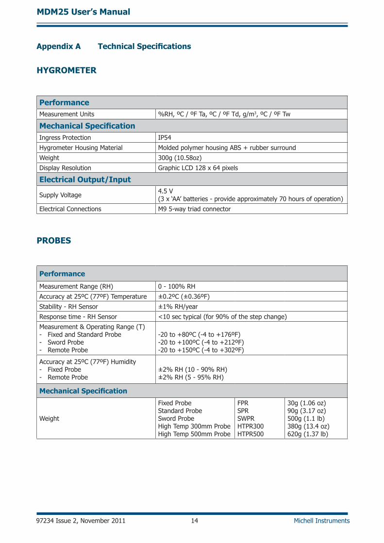
HyGRoMETER
PerformanceMeasurement units %RH, ºC / ºF Ta, ºC / ºF Td, g/m3, ºC / ºF Tw
Mechanical SpecificationIngress Protection IP54
Hygrometer Housing Material Molded polymer housing ABS + rubber surround
Weight 300g (10.58oz)
display Resolution graphic lCd 128 x 64 pixels
Electrical output/Input
Supply Voltage 4.5 V (3 x ‘AA’ batteries - provide approximately 70 hours of operation)
Electrical Connections M9 5-way triad connector
PRoBES
Performance
Measurement Range (RH) 0 - 100% RH
Accuracy at 25ºC (77ºF) Temperature ±0.2ºC (±0.36ºF)
Stability - RH Sensor ±1% RH/year
Response time - RH Sensor <10 sec typical (for 90% of the step change)
Measurement & operating Range (T)- Fixed and Standard Probe- Sword Probe- Remote Probe
-20 to +80ºC (-4 to +176ºF)-20 to +100ºC (-4 to +212ºF)-20 to +150ºC (-4 to +302ºF)
Accuracy at 25ºC (77ºF) Humidity - Fixed Probe- Remote Probe
±2% RH (10 - 90% RH)±2% RH (5 - 95% RH)
Mechanical Specification
Weight
Fixed Probe Standard Probe Sword Probe High Temp 300mm ProbeHigh Temp 500mm Probe
FPRSPRSWPRHTPR300HTPR500
30g (1.06 oz)90g (3.17 oz)500g (1.1 lb)380g (13.4 oz)620g (1.37 lb)
Appendix A Technical Specifications
MDM25 User’s Manual
Michell Instruments 15 97234 Issue 2, November 2011
Appendix B
list of Worldwide Michell Instruments’ Offices
MDM25 User’s Manual
97234 Issue 2, November 2011 16 Michell Instruments
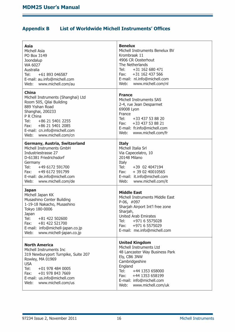
Appendix B List of Worldwide Michell Instruments’ Offices
Asia Michell AsiaPo Box 3149JoondalupWA 6027 AustraliaTel: +61 893 046587E-mail: [email protected]: www.michell.com/au
BeneluxMichell Instruments Benelux BVKrombraak 114906 CR oosterhoutThe NetherlandsTel: +31 162 680 471Fax: +31 162 437 566E-mail: [email protected]: www.michell.com/nl
ChinaMichell Instruments (Shanghai) ltdRoom 505, Qilai Building 889 Yishan Road Shanghai, 200233 P R ChinaTel: +86 21 5401 2255 Fax: +86 21 5401 2085E-mail: [email protected]: www.michell.com/cn
FranceMichell Instruments SAS2-4, rue Jean desparmet 69008 lyon FranceTel: +33 437 53 88 20Fax: +33 437 53 88 21E-mail: [email protected]: www.michell.com/fr
Germany, Austria, SwitzerlandMichell Instruments gmbHIndustriestrasse 27 d-61381 Friedrichsdorf germanyTel: +49 6172 591700 Fax: +49 6172 591799E-mail: [email protected]: www.michell.com/de
ItalyMichell Italia SrlVia Capecelatro, 10 20148 Milano ItalyTel: +39 02 4047194 Fax: + 39 02 40010565E-mail: [email protected]: www.michell.com/it
JapanMichell Japan KKMusashino Center Building 1-19-18 Nakacho, Musashino Tokyo 180-0006 JapanTel: +81 422 502600 Fax: +81 422 521700E-mail: [email protected]: www.michell-japan.co.jp
Middle EastMichell Instruments Middle EastP-06, #097Sharjah Airport Int’l free zoneSharjah, united Arab EmiratesTel: +971 6 5575028Fax: +971 6 5575029E-mail: [email protected]
north AmericaMichell Instruments Inc319 Newburyport Turnpike, Suite 207Rowley, MA 01969uSATel: +01 978 484 0005 Fax: +01 978 843 7669E-mail: [email protected] Web: www.michell.com/us
United KingdomMichell Instruments ltd48 lancaster Way Business ParkEly, CB6 3NW CambridgeshireEngland Tel: +44 1353 658000Fax: +44 1353 658199E-mail: [email protected] Web: www.michell.com/uk
MDM25 User’s Manual
Michell Instruments 17 97234 Issue 2, November 2011
noTES:

http://www.michell.com