Embed Size (px)
Citation preview

OWNER'SMANUAL
MD 35B2
JETSupplement
��������������

Copyright © 2010 Tohatsu Corporation. All rights reserved. No part of this manual may be reproduced or transmitted in any form or by any means without the express written permission of Tohatsu Corporation.

GENERAL INFORMATION ......................................................................2Before Operating Your Outboard ...................................................................................................... .2
Specifications ..................................................................................................................................... .3
Components ........................................................................................................................................4
OPERATION .............................................................................................5How the Jet Drive Operates .................................................................................................................5
Stopping the Boat in an Emergency .................................................................................................. .6
Steering the Boat ................................................................................................................................ .6
Mooring The Boat ...............................................................................................................................7
Water Intake Blockage ...................................................................................................................... .8
Clearing A Lodged Impeller .............................................................................................................. .8
Lubricating the Driveshaft Bearing .....................................................................................................9
Operating In Freezing Temperatures ...................................................................................................9
Pre-Starting Check List .......................................................................................................................9
Operating In Salt Water Or Polluted Water ......................................................................................10
Operating In Shallow Water ..............................................................................................................10
MAINTENANCE ...................................................................................... 11Impeller Removal and Installation ................................................................................................... .11
Worn/Dull Impeller ..........................................................................................................................13
Steering Pull Adjustment ...................................................................................................................13
Impeller Clearance Adjustment .........................................................................................................13
Replaceable Jet Drive Shear Key ........................................................................................................14
Shift Cable Adjustment .................................................................................................................... .15
Corrosion Control Anode ................................................................................................................. .17
Lubricating the Driveshaft Bearing .................................................................................................. .17
TROUBLESHOOTING ............................................................................19Engine Over-Speed (Excessive RPM) ............................................................................................... .19
Performance Loss .............................................................................................................................. .19
ENGINE INSTALLATION .......................................................................20Transom height of the boat .............................................................................................................. .20
Locate center line of the outboard ................................................................................................... .20
Determining the Mounting Height of the Outboard ........................................................................21
Water Testing ................................................................................................................................... .22
Index

GENERAL INFORMATION
Before Operating Your OutboardRead this manual carefully. Learn the difference in handling characteristics between a jet drive
boat and a propeller driven boat. If you have any questions, contact your dealer.
STEERING AT LOW SPEEDS
Unlike propeller driven boats, the jet drive boat tends to lose steering control as less water is drawn
in and expelled. Increase speed slightly to regain steering.
MANEUVERABILITY
The jet drive is highly maneuverable at higher speeds, more so, than propeller driven boats. Use
caution when turning to prevent spin - outs.
IN NEUTRAL
The impeller will continue to rotate while the engine is in neutral. Although the approximate
balancing of forward and reverse thrust will minimize boat movement, the boat may tend to
move slowly forward or backward. This is normal for a direct - drive jet driven boat. The operator
should be aware of this and use caution whenever the engine is running.
Safety and operating information that is practiced, along with using good common sense, can
help prevent personal injury and product damage.
This manual as well as safety labels posted on the outboard use the following safety alerts1. to
draw your attention to special safety instructions that should be followed.
������
Indicates a hazardous situation which, if not avoided, will result in death or serious injury.
�������
Indicates a hazardous situation which, if not avoided, could result in death or serious injury.
2

333
Watch for boat movement in neutral. When the jet drive is in neutral, the drive impeller
continues to rotate. Although the approximate balancing of forward and reverse thrust will
minimize boat movement, the boat may tend to move slowly forward or backward. This is normal
for a direct - drive jet driven boat. The operator should be aware of this and use caution whenever
the engine is running.
SpecificationsOwner’s manual requires the correction. Please replace specification with below specification.
MODEL MD 35B2 JET
Overall Lengh, in/mm 24.8/630
Overall Width, in/mm 13.6/345
Overall Height, in/mm 42.2/1,072
Recommended Transom Height, in/mm
20.5/521
Weight, lbs/kg 196.2/89
OutputJet power, HP/kW 35/26.1
Horsepower, HP/kW 50/36.8
Max, Operating Range 5,150 - 5,850
Number of Cylinders 3
Piston Displacement, Cu in/cc 42.5/697
Bore × Stroke, in/mm 2.68×2.52/68×64
Exhaust System Jet Exhaust
Lubrication System Oil injection
Cooling System Water cooling
Starting System Electric starter motor
Ignition Inductive Ignition
Spark Plugs NGK IZFR6Q
Alternator V . W 12V - 280W 23A
Trim Stages 4
Grease Driveshaft Bearing 3HT-65319-0
Gear Reduction Ratio 1 : 1
M25 Jet Drive

444
Components
a b
c
d
e
f gh
ij
k l
m
no
p
a
dfg
hi j
kl
n
M25 Jet Drive
a Top Cowl
b Throttle Grip
c Stop Switch Lanyard
d Reverse Lock lever
e Shift Cable
f Drive Shaft Housing
g Thrust Rod
h Water Outlet
i Jet Drive Housing
j Battery Cable
k Reverse Gate
l Water Intake Housing
m Shift Lever
n Fuel Connecter
o Stop Switch
p Main Switch

555
How the Jet Drive OperatesA jet driven boat has substantially different handling characteristics compared to a propeller
driven boat. It is recommended that the operator adjusts to these characteristics by experimenting
in open water at both high and low speeds. The driveshaft driven impeller draws water up through
the water intake and then redirects it at a high pressure through the water outlet nozzle to create
forward thrust. To obtain reverse, the reverse gate moves over the outlet nozzle to direct the water
in the opposite direction.
ac
b
a - Water intake
b - Water outlet nozzle
c - Reverse gate
When the jet drive is in neutral, the impeller continues to rotate. However, the reverse gate is
positioned so that some of the forward thrust is diverted to create reverse thrust. This approximate
balancing of forward and reverse thrust will minimize any boat movement. Because the impeller is
always rotating and creating thrust when the engine is running, the boat may tend to move slowly
forward or backward. This is normal for a direct-drive jet driven boat. The operator should be
aware of this and use caution whenever the engine is running.
OPERATIONM25 Jet Drive

666
�������Avoid injury resulting from contacting the rotating impeller or having hair, clothing, or loose objects drawn into the water intake and wrapping around the impeller shaft. Stay away from the water intake and never insert an object into the water intake or water outlet nozzle when the engine is running. The jet drive is always drawing water into the housing when the engine is running. Do not operate the jet drive with the grate removed from the water intake. Keep hands, feet, hair, loose clothing, life jackets, etc., away from the water intake. Never insert an object into the water intake or water outlet nozzle when the engine is running.
Stopping the Boat in an EmergencyA jet powered boat has emergency stopping capability unique to this form of propulsion.
�������Using the emergency stopping capability of a jet drive unit will slow down the boat in an emergency. However, sudden stopping may cause the occupants of the boat to be thrown forward or out of the boat resulting in serious injury or death. Use caution when performing the emergency stopping procedure, and be sure to practice in a safe area. In an emergency, putting the jet outboard into reverse and applying reverse throttle can rapidly slow down the boat and reduce stopping distance. However, such a maneuver may cause occupants in the boat to be thrown forward or possibly out of the boat.
Steering the BoatThe jet drive is dependent on water jet thrust for steering the boat. If the water jet thrust should
ever stop (water blockage, engine stops, etc.), the boat will slow to a stop. However, while slowing
there will be a reduced ability to steer the boat.
M25 Jet Drive

777
�������Steering the vessel in a tight turn can result in loss of boat control. In some cases, the boat can spin out or roll over, causing serious injury or death. Avoid steering beyond the capabilities of the vessel, especially at high speeds.
�������
A loss or reduction in water jet thrust will directly affect boat directional control, and may result in property damage, personal injury, or death. Boat directional control can also be substantially reduced or lost altogether by a sudden loss of power such as running out of gas, quickly backing off the throttle, turning off the ignition switch, activating the lanyard stop switch, or plugging the water intake to the jet pump. Use caution when maneuvering at high speeds in areas where debris (weeds, logs, gravel, etc.) could be picked up into the jet drive. The ability to take evasive action is dependent on sufficient water jet thrust to control the boat.While steering the boat at engine speeds above idle, the boat will respond quickly; but, due to the relatively flat-bottom hulls and lack of a gearcase in the water, the boat will tend to skid on turns. Turns must be started early and use sufficient power to maintain steeringcontrol.
Mooring The BoatBe sure to tilt the jet drive out of the water when the boat is pulled onto a beach or tied to a dock
in shallow water. Failure to do this may cause the water intake housing to fill with sand or debris
and could prevent the outboard from cranking over for starting.
M25 Jet Drive

888
Water Intake Blockage
�������A rotating impeller could cause injury if contact is made with hands, clothing, or tools. To avoid injury, keep hands and clothing away from the inlet or outlet of the jetdrive, regardless of whether the boat is in the water. Secure tools and loose items to avoid being struck by projectiles as a result of contact with the rotating impeller, and to prevent damage to the impeller.A large amount of debris being drawn into the water intake may result in a loss of power. Intake suction holding debris against the grate will result in restricted water flow. Shutting the engine off may allow the debris to fall off the intake grate allowing full power to be restored. If debris does not fall off the intake grate, the engine must be shut off and debris physically removed from the grate.
Clearing A Lodged Impeller
�������Rotating the flywheel to free a lodged impeller can accidentally start the engine, resulting in serious injury or death. Always turn the ignition key or lanyard stop switch to the “OFF” position and remove all spark plug leads from the spark plugs.It is possible for debris to lodge between the impeller and jet housing wall, especially after the engine has been stopped. This will lock the driveshaft and will prevent the engine from being able to crank over for starting. Following are steps for dislodging the impeller.
1. Position lanyard stop switch to the “OFF” position.
2. Remove spark plug leads to prevent the engine from accidentally starting.
3. Remove flywheel or rewind cover and rotate the engine flywheel
counterclockwise.
If this does not dislodge the impeller, it will be necessary to remove the six screws and water intake
housing.
M25 Jet Drive

999
Lubricating the Driveshaft BearingBefore each use, lubricate the driveshaft bearing. Refer to Maintenance - Lubricating the
Driveshaft Bearing.
Operating In Freezing TemperaturesIf there is a chance of ice forming on the water, the jet drive should be raised out of the water and
drained completely of water. If ice should form at the water level inside the outboard driveshaft
housing, it will block water flow to the engine causing possible damage. Do not start the engine
until the ice is clear.
Pre-Starting Check List• Operator knows safe navigation, boating, and operating procedures.
• An approved personal flotation device of suitable size for each person aboard and readily
accessible (it is the law).
• A ring type life buoy or buoyant cushion designed to be thrown to a person in the water.
• Know your boats maximum load capacity. Look at the boat capacity plate.
• Fuel supply OK.
• Ensure the boat drain plug is installed.
• Arrange passengers and load in the boat so the weight is distributed evenly and everyone is
seated in a proper seat.
• Tell someone where you are going and when you expect to return.
M25 Jet Drive

101010
• Know the waters and area you will be boating; tides, currents, sand bars, rocks, and other
hazards.
• Check steering for free operation.
• Check for debris around the rudder and reverse gate which may jam or hinder operation.
• Before launching, examine the jet drive water intake for obstructions which may prevent
pumping of water.
• Ensure the driveshaft bearing on the jet drive is lubricated.
Operating In Salt Water Or Polluted WaterIf the boat is kept moored in the water, always tilt the outboard so the water intake is completely
out of water when not in use.
Wash down the outboard exterior and flush out the exhaust outlet of the jet drive with fresh water
after each use.
When used in salt water more than in fresh water, remove mounting hardware, grease, and
reassemble once a year. Failure to do this may result in hardware that is difficult if not impossible
to remove at a later date.
Operating In Shallow WaterThe life of the impeller and water intake can be greatly increased by avoiding the intake of sand
and gravel. The intake suction will act like a dredge when the water intake comes close to the
bottom. It is better to stop the engine and drift up to shore when landing, and to shove off with
an oar when leaving. The engine can idle through areas of water less than 61 cm (2 ft.) deep, but
there should be more than 61 cm (2 ft.) of water under the boat when increasing speed to reach
full plane.
Once the boat is on plane, the boat speed will prevent the ingestion of gravel and other debris
from the bottom. The suction is still present, but the water intake passes too quickly over the
bottom to allow debris to be drawn into the water intake.
When boating through shallow water areas, choose a course of travel that avoids sharp rocks and
other underwater obstacles that could damage the boat. Running the boat through these areas on
full plane may be helpful as the boat will be riding higher in the water. If the boat gets stuck on
the bottom, immediately stop the engine and move the boat to deeper water.
M25 Jet Drive

111111
Impeller Removal and Installation
�������Rotating the driveshaft may cause the engine to crank over and start. To prevent this type of accidental engine starting and possible serious injury caused from being struck by a rotating impeller, always turn the ignition key or lanyard stop switch to the “OFF” position and remove the spark plug leads from the spark plugs while servicing the impeller.
1. Position the key switch or lanyard stop switch to the “OFF” position.
2. Remove the spark plug leads to prevent the engine from starting.
3. Remove the six screws securing the water intake housing, and remove the
water intake housing.
MAINTENANCEM25 Jet Drive

121212
4. Straighten the bent tabs on the impeller nut retainer and remove the impeller
nut.
a - Tabs b - Impeller nut
5 . Pull the impeller straight off the shaft.
If the impeller is tight, use a hammer and a block of wood to rotate the impeller clockwise on the
shaft until the keyway is directly above the flat on the shaft. This will free the jammed key and
allow removal.
b a
M25 Jet Drive

131313
Worn/Dull ImpellerThe intake of gravel through the pump can round off and wear the leading edges of the impeller.
Some conditions that could be experienced from a worn/dull impeller are as follows:
• Noticeable performance loss, especially on acceleration
• Difficulty getting the boat on plane
• An increase in engine RPM at wide open throttle
IMPORTANT : Do not sharpen or alter the top side lifting angle. Check the impeller
blades occasionally for damage. Use a flat file to resharpen the leading
edges. Sharpen to a 0.8 mm (1/32 in.) radius by removing material from
bottom side only.
Steering Pull AdjustmentThe steering on some boats will have the tendency to pull
towards starboard. This pulling condition can be corrected by
using a pliers and bending the ends of the exhaust fins 1/16 in.
(1.5mm) toward the starboard side of the outboard.
Impeller Clearance AdjustmentThe impeller should be adjusted so there is approximately 0.8 mm (0.031 in.) clearance between
the impeller edge and liner. Operating the jet drive in waters that contain sand and gravel can
cause wear to the impeller blades, and the clearance will start to exceed 0.8 mm (0.031 in.).
a - Exhaust fin
b
aa - Leading edge b - Top side lifting angle
M25 Jet Drive

141414
As the blades wear, shims located in the stack outside of the impeller can be transferred behind
the impeller. This will move the impeller further down into the tapered liner to reduce the
clearance.
a - Shims
b - Clearance between impeller edge and liner
Check the impeller clearance by sliding a feeler gauge through the intake grate and measure
the clearance between the impeller edge and liner. If adjustment is required, refer to Impeller
Removal and Installation.
Replaceable Jet Drive Shear KeyThe jet drive is equipped with a shear key to protect it in the event of a lodged impeller. The shear
key can be reached by removing the water intake housing and impeller. Grease the drive shaft,
shear key, and impeller bore when replace these parts. Refer to Maintenance-Impeller Removal
and Installation.
a
b
M25 Jet Drive

151515
Shift Cable Adjustment
�������Pressurized water hitting the reverse gate may cause it to engage, causing sudden and unexpected slowing of the boat. This can cause serious injury or death from occupants being thrown within or out of the boat. Adjust the shift link rod to lock the reverse gate, preventing it from interfering with water flow.
CHECKING SHIFT LINK ROD ADJUSTMENT
Check the shift link rod adjustment in forward shift position. The correct adjustment will position the
shift cam far enough on the roller in order to lock the reverse gate into forward position. The reverse
gate should not be able to be forced up towards neutral. Pull on the reverse gate by hand to verify.
a
b
c
d
e a
b
cd
d
F type P type
a - Shift cableb - Shift cam
c - Rollerd - Reverse gate e - Ball end
M25 Jet Drive

161616
1. Place roller at bottom of shift cam groove as shown.
Correct Incorrect
2. Place the shift lever and shift cam into full forward position.
3. Bring groove A to position B and secure the part.
B
A
M25 Jet Drive

171717
4. Attach ball end to shift cable, align the hole as shown, and secure the part.
5. The reverse gate should not be able to be forced up towards neutral.
Pull on the reverse gate by hand to verify.
M25 Jet Drive

181818
Corrosion Control AnodeAn anode helps protect the outboard against galvanic corrosion by sacrificing its metal to be
slowly corroded instead of the outboard metals.
An anode is located on the water intake housing. An anode requires periodic inspection, especially
in salt water which will accelerate the erosion. To maintain this corrosion protection, always
replace the anode before it is completely eroded. Never paint or apply a protective coating on the
anode as this will reduce effectiveness of the anode.
a - Water intake housing anode
Lubricating the Driveshaft BearingLubricate the driveshaft bearing before each use.
Description Where to used Part No.
Grease Drive shaft bearing 3HT-72309-0
Grease Gun Drive shaft bearing 3HT-65324-0
IMPORTANT : It is important not to use a general all purpose grease for this bearing.
The lubricant recommended is a water resistant grease of the proper
consistency for this application. If a substitute is used, be sure that it is
water resistant and of the same consistency.
a
M25 Jet Drive

191919
1. Pull the vent hose off of the grease fitting.
2. Pump in grease through the grease fitting, using the grease gun provided,
until excess grease starts to exit the vent hose.
3. Reconnect the vent hose onto the grease fitting after greasing.
a - Grease fitting b - Vent hose
NOTE : After 30 hours of operation, pump in extra grease to purge out any moisture.
Visually inspecting the purged grease at this time will give an indication of
conditions inside the bearing housing. A gradual increase in moisture content
indicates seal wear. If the grease begins to turn dark or dirty gray, the driveshaft
bearing and seals should be inspected and replaced if necessary. Some discoloration
of the grease is normal during the break-in period on a new set of seals.
a
b
M25 Jet Drive

202020
Engine Over-Speed (Excessive RPM)
POSSIBLE CAUSES
• Outboard mounted too high on the transom.
• Worn jet pump impeller or liner.
• Incorrect jet pump impeller clearance adjustment.
• Tilting the outboard out beyond a vertical position.
• Cavitation of the impeller due to rough water or obstruction in the boat hull.
• Blockage of the water intake.
Performance Loss
POSSIBLE CAUSES
• Throttle not fully open.
• Damaged impeller.
• Incorrect engine timing, adjustments, or setup.
• Boat overloaded or load improperly distributed.
• Excessive water in bilge.
• Boat bottom is dirty or damaged.
TROUBLESHOOTINGM25 Jet Drive

212121
Transom height of the boatOutboards with jet drives will be mounted approximately 7 inches higher on the transom than
propeller driven outboards. This requires outboards than have a 15 in. shaft length to be installed
on boats having a 22 in. transom height.
If the boat transom is of insufficient height, and the outboard cannot be installed to the
recommended height, cantact the boat manufacturer for recommended procedure to build up
the boat transom.
Locate center line of the outboardLocate (and mark with pencil) the vertical centerline (a) of boat transom.
a
C D
A B
a - Centerline of transom
C
C = 521 mm / 20.5 in
ENGINE INSTALLATIONM25 Jet Drive

222222
Determining the Mounting Height of the OutboardThe following outboard mounting height settings will work good for most applications, however,
because of different boat/hull designs, the setting should be rechecked by test running the boat.
Refer to Water Testing.
• Installing the outboard too high on the transom will allow the water intake to suck in air and
cause cavitation. Cavitation causes the engine to overspeed in spurts and reduce thrust. This
condition should be avoided by proper height setting.
• Installing the outboard too low on the transom will allow excessive drag.
BOATS WITH A “V” BOTTOM HULL
1. Measure the width of the leading edge on the water intake housing.
Make a horizontal line on the transom up from the “V” bottom the same length as the width of
the water intake housing.
a
b
a - Horizontal line
b - Width of the leading edge on the water intake housing
2. Place (center) the outboard on the boat transom.
Set the height of the outboard on the boat transom so that the front edge of the water intake
housing is in line with the horizontal line made in step 1. Fasten the outboard to the transom at
this height.
232323
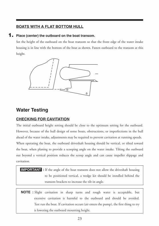
BOATS WITH A FLAT BOTTOM HULL
1. Place (center) the outboard on the boat transom.
Set the height of the outboard on the boat transom so that the front edge of the water intake
housing is in line with the bottom of the boat as shown. Fasten outboard to the transom at this
height.
Water Testing
CHECKING FOR CAVITATION
The initial outboard height setting should be close to the optimum setting for the outboard.
However, because of the hull design of some boats, obstructions, or imperfections in the hull
ahead of the water intake, adjustments may be required to prevent cavitation at running speeds.
When operating the boat, the outboard driveshaft housing should be vertical, or tilted toward
the boat, when planing to provide a scooping angle on the water intake. Tilting the outboard
out beyond a vertical position reduces the scoop angle and can cause impeller slippage and
cavitation.
IMPORTANT : If the angle of the boat transom does not allow the driveshaft housing
to be positioned vertical, a wedge kit should be installed behind the
transom brackets to increase the tilt-in angle.
NOTE : Slight cavitation in sharp turns and rough water is acceptable, but
excessive cavitation is harmful to the outboard and should be avoided.
Test run the boat. If cavitation occurs (air enters the pump), the first thing to try
is lowering the outboard mounting height.
M25 Jet Drive

24
If cavitation still exists after lowering the outboard, it may be helpful to seek advice from the boat
manufacturer.
Another option to further reduce cavitation is a rough water plate. A rough water plate may be
helpful in reducing cavitation when running in windy, rough water conditions where air is sucked
into the water intake when jumping waves. Install a 0.8 mm (1/32 in.) metal plate that extends
from the hull bottom to the top of the water intake housing. This plate tends to reduce air intake
as well as reduce spray.
a
a - Rough water plate
M25 Jet Drive

2525

TOHATSU CORPORATIONAddress : 5-4, 3-chome, Azusawa, Itabashi-ku, TOKYO, 174-0051 JAPANPhone : TOKYO (03)3966-3117FAX : TOKYO (03)3966-2951URL : www.tohatsu.co.jp
Supplement
003-11095-01003-NB0050
Printed in Japan
OWNER'S MANUAL
MD 35B2
JET