Embed Size (px)
Citation preview
MD RECORDER
B60-4261-00
KENWOOD CORPORATION
INSTRUCTION MANUAL
DM-VH7
Before installation, read the section entitled “Installation” for correctinstallation. 0
EN
2DM-VH7 (EN)
Before applying powerUnits are designed for operation as follows.
U.S.A. ................................................................... AC 120 V onlyEurope & U.K. ..................................................... AC 230 V only
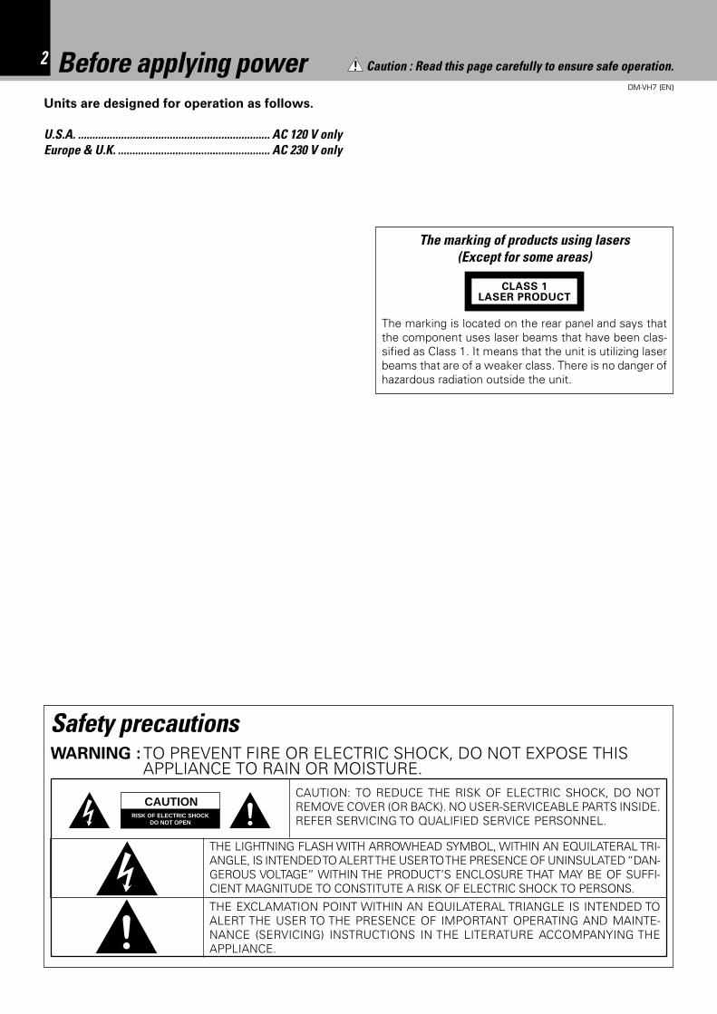
The marking is located on the rear panel and says thatthe component uses laser beams that have been clas-sified as Class 1. It means that the unit is utilizing laserbeams that are of a weaker class. There is no danger ofhazardous radiation outside the unit.
CLASS 1LASER PRODUCT
The marking of products using lasers(Except for some areas)
Caution : Read this page carefully to ensure safe operation.
Safety precautionsWARNING : TO PREVENT FIRE OR ELECTRIC SHOCK, DO NOT EXPOSE THIS
APPLIANCE TO RAIN OR MOISTURE.CAUTION: TO REDUCE THE RISK OF ELECTRIC SHOCK, DO NOTREMOVE COVER (OR BACK). NO USER-SERVICEABLE PARTS INSIDE.REFER SERVICING TO QUALIFIED SERVICE PERSONNEL.
RISK OF ELECTRIC SHOCKDO NOT OPEN
THE LIGHTNING FLASH WITH ARROWHEAD SYMBOL, WITHIN AN EQUILATERAL TRI-ANGLE, IS INTENDED TO ALERT THE USER TO THE PRESENCE OF UNINSULATED “DAN-GEROUS VOLTAGE” WITHIN THE PRODUCT’S ENCLOSURE THAT MAY BE OF SUFFI-CIENT MAGNITUDE TO CONSTITUTE A RISK OF ELECTRIC SHOCK TO PERSONS.
THE EXCLAMATION POINT WITHIN AN EQUILATERAL TRIANGLE IS INTENDED TOALERT THE USER TO THE PRESENCE OF IMPORTANT OPERATING AND MAINTE-NANCE (SERVICING) INSTRUCTIONS IN THE LITERATURE ACCOMPANYING THEAPPLIANCE.
CAUTION
3DM-VH7 (EN)
Contents Caution : Read the pages marked carefully to ensure safe operation.
Before applying power .........................................................................................................2
Safety precautions ..............................................................................................................2IMPORTANT SAFEGUARDS.................................................................................................4
Before operation ...................................................................................................................6
Accessories ........................................................................................................................6Special feature ....................................................................................................................7Safety Precautions .............................................................................................................8Maintenance .......................................................................................................................9
Installation ...........................................................................................................................10
Changing the installation method.....................................................................................10How to replace the front feet ...........................................................................................11
System connections ...........................................................................................................12
System operation features ...............................................................................................13Names and functions of parts ...........................................................................................14
Display/Main unit ..............................................................................................................14Remote control unit ..........................................................................................................15
Operation of remote control unit ......................................................................................16
Playback of Mini Disc..........................................................................................................17
Playing tracks in order from track No. 1 ........................................................................... 17Playback from desired track .............................................................................................18Listening in random order (RANDOM playback) ..............................................................18Searching a desired track by its title (TITLE SEARCH) .....................................................20
Programming ......................................................................................................................21
Programming tracks in a desired order ............................................................................21Repeated playback ...........................................................................................................23
Systematized recording features ......................................................................................24
Recording a single CD track (O.T.E.) ................................................................................24Recording all tracks on a CD (O.T.E.) ...............................................................................24Synchro recording with CD player ....................................................................................25
Recording .............................................................................................................................26
General recording .............................................................................................................26Starting recording from the sound before the current sound (MEMORY REC) ............... 28REC MODE key ................................................................................................................28
Changing the displayed contents .....................................................................................30
TIME DISP. key ................................................................................................................30MONITOR key ..................................................................................................................30REC INPUT switching.......................................................................................................30
Editing ..................................................................................................................................31
Selecting the editing function type ..................................................................................31Moving the order of the track being played in a disc (MOVE) .........................................32Reordering several tracks at a time (QUICK MOVE) ........................................................34Dividing a track during playback (DIVIDE) ........................................................................36Combining tracks during playback (COMBINE) ................................................................38Erasing several tracks at a time (QUICK ERASE) ............................................................. 40Erasing a single track during playback (ERASE) ...............................................................42How to edit titles ..............................................................................................................43
In case of difficulty ..............................................................................................................47
Specifications ......................................................................................................................50
Before applying power
4DM-VH7 (EN)
IMPORTANT SAFEGUARDS
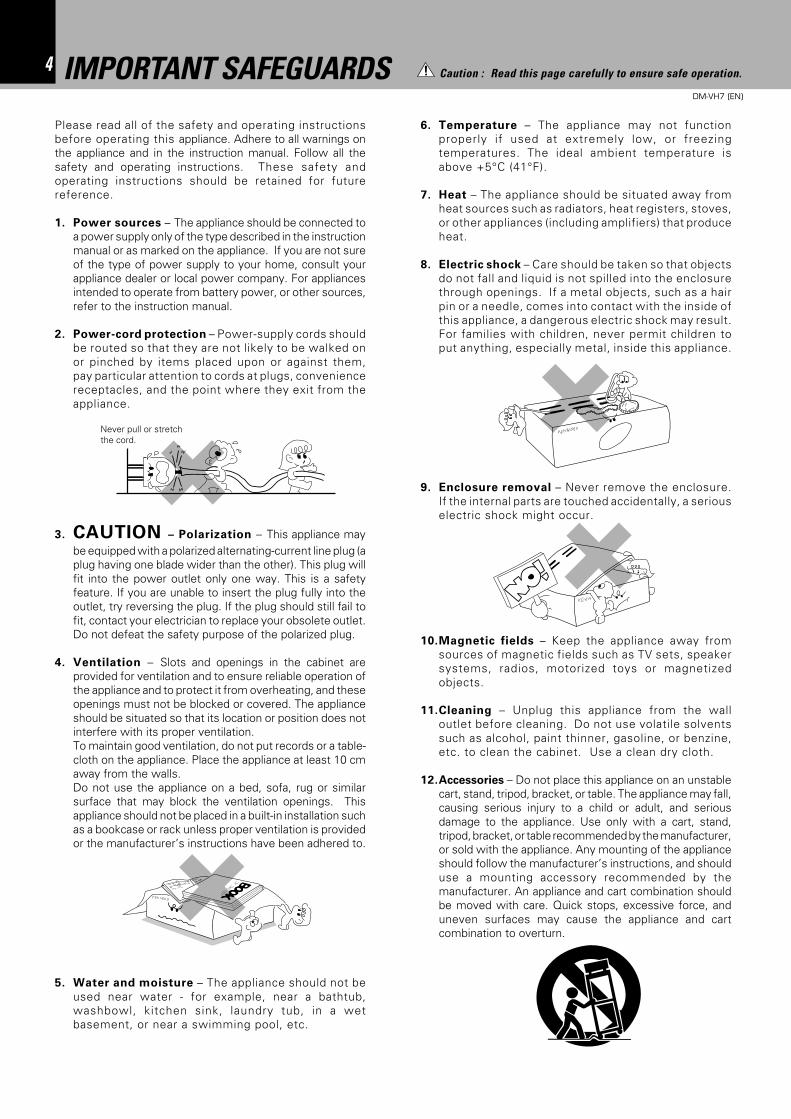
6. Temperature – The appliance may not functionproperly if used at extremely low, or freezingtemperatures. The ideal ambient temperature isabove +5°C (41°F).
7. Heat – The appliance should be situated away fromheat sources such as radiators, heat registers, stoves,or other appliances (including amplifiers) that produceheat.
8. Electric shock – Care should be taken so that objectsdo not fall and liquid is not spilled into the enclosurethrough openings. If a metal objects, such as a hairpin or a needle, comes into contact with the inside ofthis appliance, a dangerous electric shock may result.For families with children, never permit children toput anything, especially metal, inside this appliance.
9. Enclosure removal – Never remove the enclosure.If the internal parts are touched accidentally, a seriouselectric shock might occur.
10.Magnetic fields – Keep the appliance away fromsources of magnetic fields such as TV sets, speakersystems, radios, motorized toys or magnetizedobjects.
11.Cleaning – Unplug this appliance from the walloutlet before cleaning. Do not use volatile solventssuch as alcohol, paint thinner, gasoline, or benzine,etc. to clean the cabinet. Use a clean dry cloth.
12.Accessories – Do not place this appliance on an unstablecart, stand, tripod, bracket, or table. The appliance may fall,causing serious injury to a child or adult, and seriousdamage to the appliance. Use only with a cart, stand,tripod, bracket, or table recommended by the manufacturer,or sold with the appliance. Any mounting of the applianceshould follow the manufacturer’s instructions, and shoulduse a mounting accessory recommended by themanufacturer. An appliance and cart combination shouldbe moved with care. Quick stops, excessive force, anduneven surfaces may cause the appliance and cartcombination to overturn.
Please read all of the safety and operating instructionsbefore operating this appliance. Adhere to all warnings onthe appliance and in the instruction manual. Follow all thesafety and operating instructions. These safety andoperating instructions should be retained for futurereference.
1. Power sources – The appliance should be connected toa power supply only of the type described in the instructionmanual or as marked on the appliance. If you are not sureof the type of power supply to your home, consult yourappliance dealer or local power company. For appliancesintended to operate from battery power, or other sources,refer to the instruction manual.
2. Power-cord protection – Power-supply cords shouldbe routed so that they are not likely to be walked onor pinched by items placed upon or against them,pay particular attention to cords at plugs, conveniencereceptacles, and the point where they exit from theappliance.
3. CAUTION – Polarization – This appliance maybe equipped with a polarized alternating-current line plug (aplug having one blade wider than the other). This plug willfit into the power outlet only one way. This is a safetyfeature. If you are unable to insert the plug fully into theoutlet, try reversing the plug. If the plug should still fail tofit, contact your electrician to replace your obsolete outlet.Do not defeat the safety purpose of the polarized plug.
4. Ventilation – Slots and openings in the cabinet areprovided for ventilation and to ensure reliable operation ofthe appliance and to protect it from overheating, and theseopenings must not be blocked or covered. The applianceshould be situated so that its location or position does notinterfere with its proper ventilation.To maintain good ventilation, do not put records or a table-cloth on the appliance. Place the appliance at least 10 cmaway from the walls.Do not use the appliance on a bed, sofa, rug or similarsurface that may block the ventilation openings. Thisappliance should not be placed in a built-in installation suchas a bookcase or rack unless proper ventilation is providedor the manufacturer’s instructions have been adhered to.
5. Water and moisture – The appliance should not beused near water - for example, near a bathtub,washbowl, kitchen sink, laundry tub, in a wetbasement, or near a swimming pool, etc.
Never pull or stretchthe cord.
Caution : Read this page carefully to ensure safe operation.
5DM-VH7 (EN)
13.Lightning – For added protection for this appliance duringa lightning storm, or when it is left unattended and unusedfor long periods of time, unplug it from the wall outlet anddisconnect the antenna or cable system. This will preventdamage to the appliance due to lightning and power-linesurges.
14.Abnormal smell – If an abnormal smell or smoke isdetected, immediately turn the power OFF and unplugthe appliance from the wall outlet. Contact your dealer ornearest service center.
15.Damage requiring service – The appliance shouldbe serviced by qualified service personnel when:A. The power-supply cord or the plug has beendamaged.B. Objects have fallen, or liquid has been spilled intothe appliance.C. The appliance has been exposed to rain or water.D. The appliance does not appear to operate normallyby following the instruction manual. Adjust only thosecontrols that are covered by the instruction manual as animproper adjustment of other controls may result in damageand will often require extensive work by a qualifiedtechnician to restore the appliance to its normal operation.E. The appliance has been dropped, or the enclosuredamaged.F. The appliance exhibits a marked change in performance.
16.Servicing – The user should not attempt to servicethe appliance beyond that described in the instructionmanual. All other servicing should be referred toqualified service personnel.
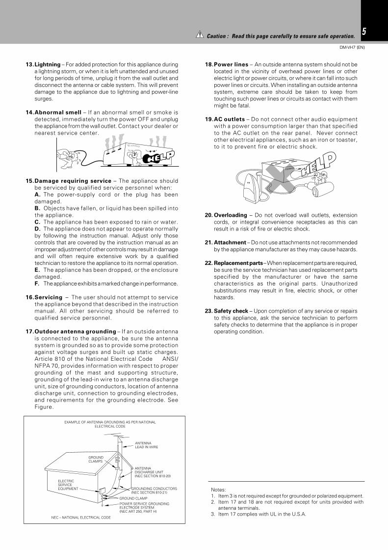
17.Outdoor antenna grounding – If an outside antennais connected to the appliance, be sure the antennasystem is grounded so as to provide some protectionagainst voltage surges and built up static charges.Article 810 of the National Electrical Code ANSI/NFPA 70, provides information with respect to propergrounding of the mast and supporting structure,grounding of the lead-in wire to an antenna dischargeunit, size of grounding conductors, location of antennadischarge unit, connection to grounding electrodes,and requirements for the grounding electrode. SeeFigure.
18.Power lines – An outside antenna system should not belocated in the vicinity of overhead power lines or otherelectric light or power circuits, or where it can fall into suchpower lines or circuits. When installing an outside antennasystem, extreme care should be taken to keep fromtouching such power lines or circuits as contact with themmight be fatal.
19.AC outlets – Do not connect other audio equipmentwith a power consumption larger than that specifiedto the AC outlet on the rear panel. Never connectother electrical appliances, such as an iron or toaster,to it to prevent fire or electric shock.
20. Overloading – Do not overload wall outlets, extensioncords, or integral convenience receptacles as this canresult in a risk of fire or electric shock.
21. Attachment – Do not use attachments not recommendedby the appliance manufacturer as they may cause hazards.
22. Replacement parts – When replacement parts are required,be sure the service technician has used replacement partsspecified by the manufacturer or have the samecharacteristics as the original parts. Unauthorizedsubstitutions may result in fire, electric shock, or otherhazards.
23. Safety check – Upon completion of any service or repairsto this appliance, ask the service technician to performsafety checks to determine that the appliance is in properoperating condition.
Notes:1. Item 3 is not required except for grounded or polarized equipment.2. Item 17 and 18 are not required except for units provided with
antenna terminals.3. Item 17 complies with UL in the U.S.A.
EXAMPLE OF ANTENNA GROUNDING AS PER NATIONALELECTRICAL CODE
POWER SERVICE GROUNDINGELECTRODE SYSTEM(NEC ART 250, PART H)
NEC – NATIONAL ELECTRICAL CODE
GROUNDING CONDUCTORS(NEC SECTION 810-21)
ANTENNALEAD IN WIRE
ANTENNADISCHARGE UNIT(NEC SECTION 810-20)
GROUND CLAMP
ELECTRICSERVICEEQUIPMENT
GROUNDCLAMPS
Caution : Read this page carefully to ensure safe operation.
6 Before operation
DM-VH7 (EN)
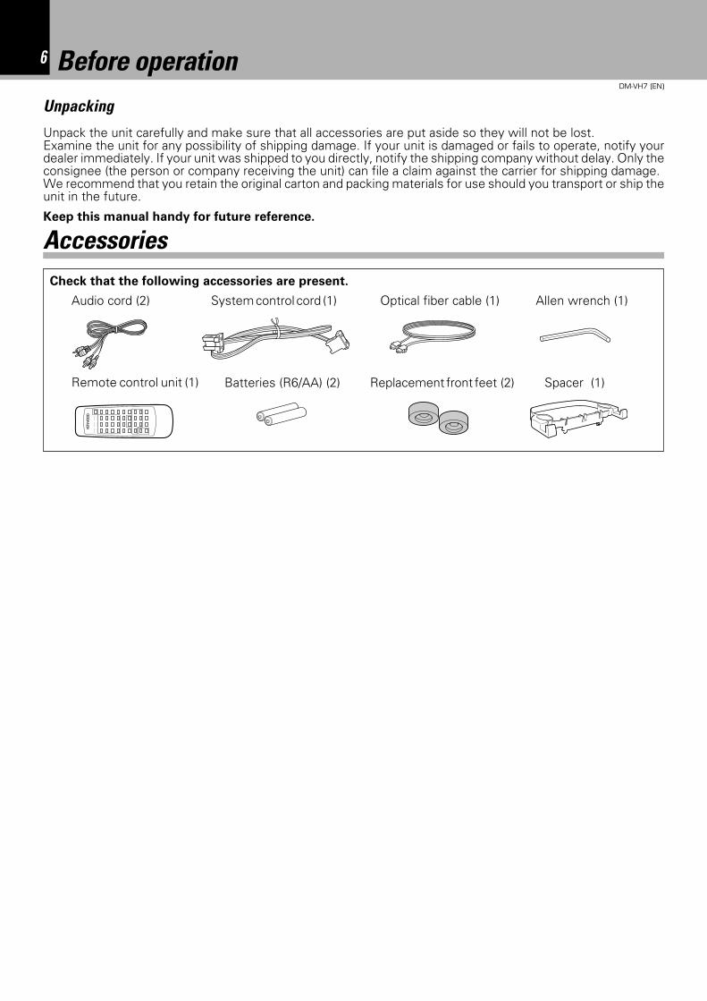
Before operationUnpacking
Unpack the unit carefully and make sure that all accessories are put aside so they will not be lost.Examine the unit for any possibility of shipping damage. If your unit is damaged or fails to operate, notify yourdealer immediately. If your unit was shipped to you directly, notify the shipping company without delay. Only theconsignee (the person or company receiving the unit) can file a claim against the carrier for shipping damage.We recommend that you retain the original carton and packing materials for use should you transport or ship theunit in the future.
Audio cord (2) System control cord (1) Optical fiber cable (1)
Remote control unit (1) Batteries (R6/AA) (2)
Check that the following accessories are present.
Keep this manual handy for future reference.
Accessories
Spacer (1)Replacement front feet (2)
Allen wrench (1)
7Before operation
DM-VH7 (EN)
This unit is audio equipment based on the Mini Disc format. The Mini Disc (MD) is an application of the opticaland magneto-optical technology and has the capability to record signals on discs.The operability of the MD isequivalent to the Compact Disc (CD). The MD uses optional non-contact system so the recordings are notdegraded by eternal factors and the discs are never scratched or damaged in playback.
Special feature
In addition to usual editing modes (MOVE, DIVIDE, COMBINE
and ERASE), this unit incorporates versatile editing features
such as QUICK MOVE for reordering the tracks in an MD
simultaneously and QUICK ERASE for erasing desired tracks.
Various editing features
The titles of tracks recorded onto an MD can be assigned and
stored in the MD. The title search facility allows you to search
desired tracks by their titles.
Title input & title search
The unit can be installed vertically on the side as well as the
conventional, horizontal installation. Much freer system set-
ting than before is now possible.
Free layout
The recording level adjustment which used to be possible
only with analog input signals is now available with digital
input signals.
Digital recording volume control
When the unit is used in combination with the CD receiver
(RD-VH7), the desired track in a CD can be recorded onto sn
MD with a single operation (O.T.E.: One Touch Edit).
Simplified CD recording (O.T.E.)
Even when the unit is off (STANDBY mode of power), play-
back can be started easily by simply pressing the play key on
the front panel.
Simplified playback with a one-touch operation
The unit incorporates a sampling rate converter to handle
different kinds of digital sources (32kHz, 44.1kHz, 48kHz).
Sampling rate converter
8 Before operation
DM-VH7 (EN)
Installation positionThe MD recorder is very sensitive to vibrations. It shouldbe installed in a position subject to as small vibration aspossible.
Memory backupThe memory storage is held for about a day after thepower cord has been unplugged from the power outlet.In case the power supply has stopped or the power cordhas been left unplugged for an extended period of time,the information related to recording and editing (re-corded at the moment a Mini Disc is ejected) may becleared or destroyed before it is recorded on the disc.The lost information cannot be recovered later.To ensure the recording of the recording and editing-related information on the Mini Disc, be sure to eject theMini Disc after every recording or editing operation.
US and foreign patents licensed from Dolby Laborato-ries.
Safety Precautions
Caution on condensationCondensation (of dew) may occur inside the unit whenthere is a great difference in temperature between thisunit and the outside.This unit may not function properly if condensationoccurs. In this case, leave the unit for a few hours withthe power left ON, and restart the operation after thecondensation has dride up.
Be specially cautious against condensatin in a followingcircumsatance:
When this unit is carried from a place to another acrossa large difference in temperature, when the humidityin the room where this unit is installed increases, etc.
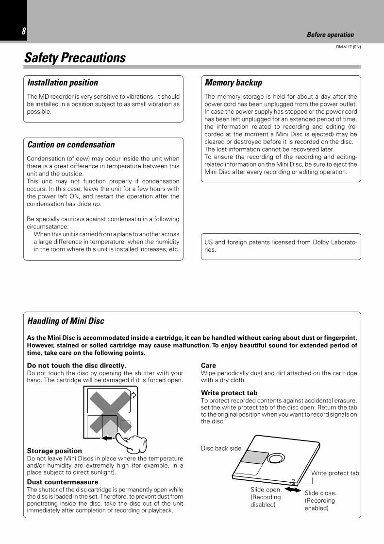
Write protect tabTo protect recorded contents against accidental erasure,set the write protect tab of the disc open. Return the tabto the original position when you want to record signals onthe disc.
CareWipe periodically dust and dirt attached on the cartridgewith a dry cloth.
Write protect tab
Slide close.(Recordingenabled)
Disc back side
Do not touch the disc directly.Do not touch the disc by opening the shutter with yourhand. The cartridge will be damaged if it is forced open.
Storage positionDo not leave Mini Discs in place where the temperatureand/or humidity are extremely high (for example, in aplace subject to direct sunlight).
Handling of Mini Disc
As the Mini Disc is accommodated inside a cartridge, it can be handled without caring about dust or fingerprint.
However, stained or soiled cartridge may cause malfunction. To enjoy beautiful sound for extended period of
time, take care on the following points.
Slide open.(Recordingdisabled)
Dust countermeasureThe shutter of the disc cartridge is permanently open whilethe disc is loaded in the set. Therefore, to prevent dust frompenetrating inside the disc, take the disc out of the unitimmediately after completion of recording or playback.
9Before operation
DM-VH7 (EN)
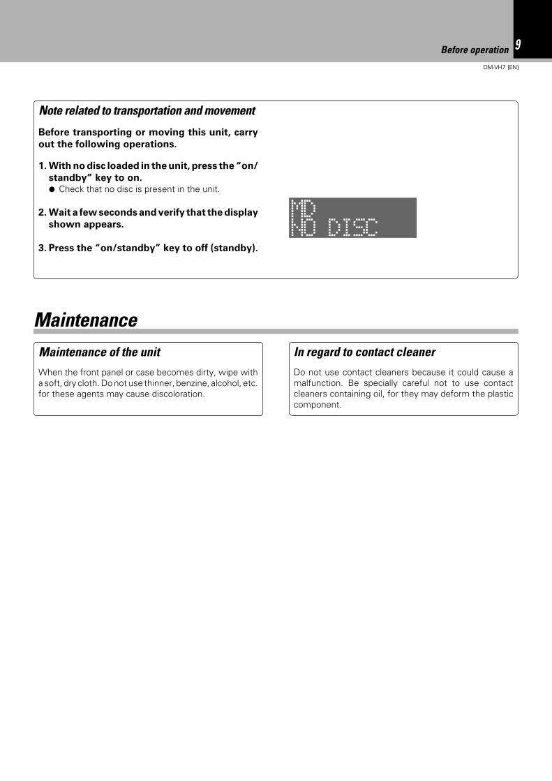
Note related to transportation and movement
Before transporting or moving this unit, carry
out the following operations.
1. With no disc loaded in the unit, press the “on/
standby” key to on.¶ Check that no disc is present in the unit.
2. Wait a few seconds and verify that the display
shown appears.
3. Press the “on/standby” key to off (standby).
Maintenance of the unitWhen the front panel or case becomes dirty, wipe witha soft, dry cloth. Do not use thinner, benzine, alcohol, etc.for these agents may cause discoloration.
In regard to contact cleanerDo not use contact cleaners because it could cause amalfunction. Be specially careful not to use contactcleaners containing oil, for they may deform the plasticcomponent.
Maintenance
NO DISCMD
10DM-VH7 (EN)
InstallationThe front feet attached at the factory can be replaced with the provided replacement feet.
When you want to stack the RD-VH7 (optional) above this unit, installed this unit horizontally by using
the provided horizontal installation spacer.
÷ Remove the MD and unplug the power cord be-fore proceeding to the following operation.
÷ Only the front feet can be replaced.÷ When attaching replacement front feet, use only
the screws which have been used with the re-moved feet. (Using other screws may result in afire or malfunction.)
÷ If this unit is fell down by mistake after installationand if an MD is left inside the unit, the MD may bedamaged.
Check the following accessoriesReplacement front feet .................................... 2
Spacer for horizontal installation.................... 1
Allen wrench ..................................................... 1
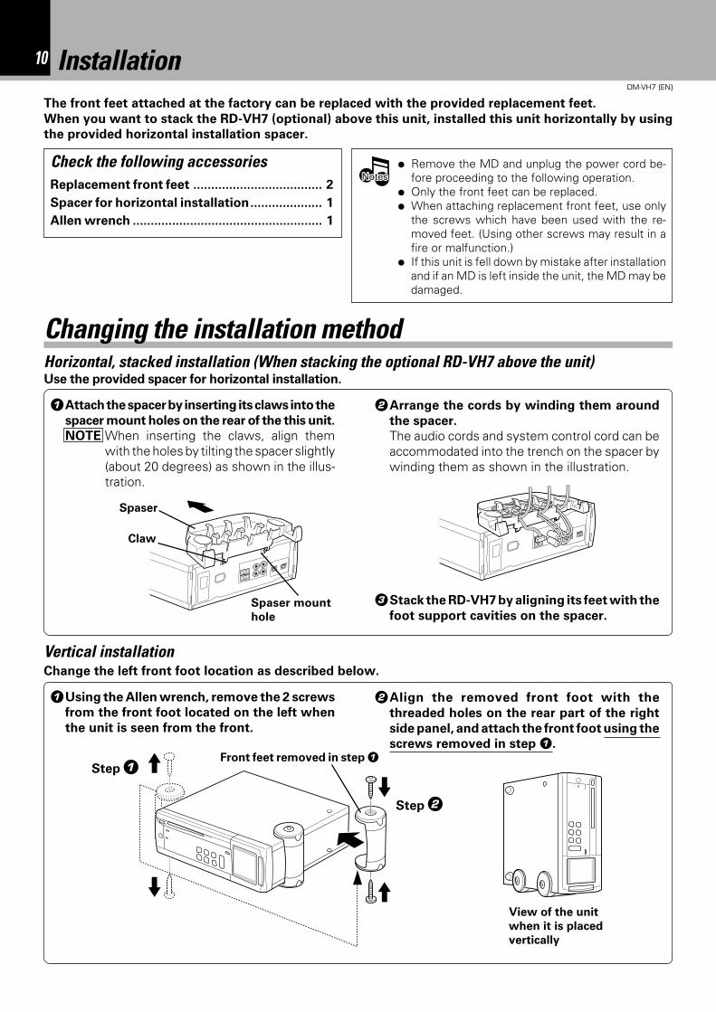
1Using the Allen wrench, remove the 2 screws
from the front foot located on the left when
the unit is seen from the front.
View of the unit
when it is placed
vertically
1Attach the spacer by inserting its claws into the
spacer mount holes on the rear of the this unit.
NOTE When inserting the claws, align themwith the holes by tilting the spacer slightly(about 20 degrees) as shown in the illus-tration.
2Arrange the cords by winding them around
the spacer.
The audio cords and system control cord can beaccommodated into the trench on the spacer bywinding them as shown in the illustration.
Horizontal, stacked installation (When stacking the optional RD-VH7 above the unit)
Vertical installation
NotesNotesNotes
Step 1
Step 2
Front feet removed in step 1
Use the provided spacer for horizontal installation.
Spaser
Claw
Change the left front foot location as described below.
2Align the removed front foot with the
threaded holes on the rear part of the right
side panel, and attach the front foot using the
screws removed in step 1.
Changing the installation method
3Stack the RD-VH7 by aligning its feet with the
foot support cavities on the spacer.Spaser mount
hole
11System connections
DM-VH7 (EN)
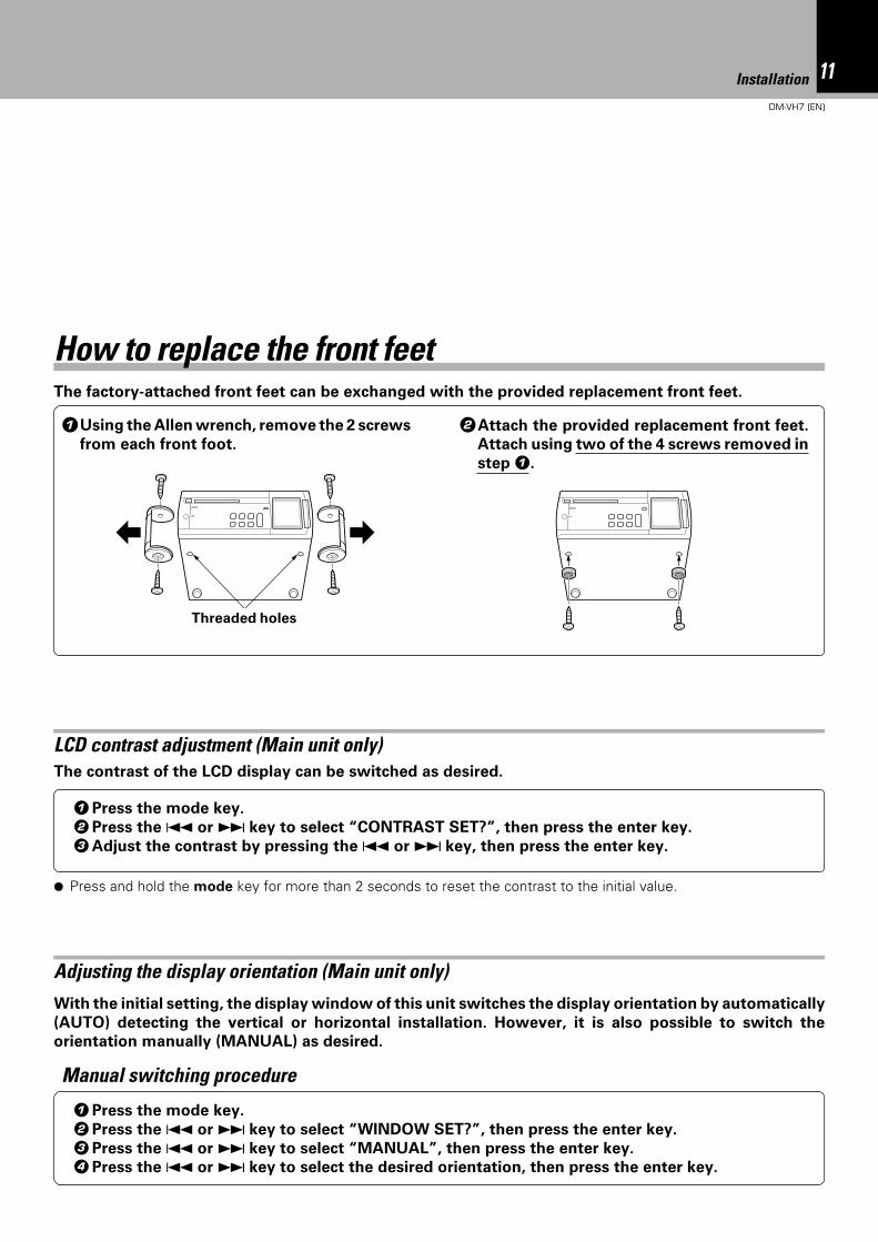
The factory-attached front feet can be exchanged with the provided replacement front feet.
Threaded holes
1Using the Allen wrench, remove the 2 screws
from each front foot.
2Attach the provided replacement front feet.
Attach using two of the 4 screws removed in
step 1.
With the initial setting, the display window of this unit switches the display orientation by automatically
(AUTO) detecting the vertical or horizontal installation. However, it is also possible to switch the
orientation manually (MANUAL) as desired.
Adjusting the display orientation (Main unit only)
1Press the mode key.
2Press the 4 or ¢ key to select “WINDOW SET?”, then press the enter key.
3Press the 4 or ¢ key to select “MANUAL”, then press the enter key.
4Press the 4 or ¢ key to select the desired orientation, then press the enter key.
Manual switching procedure
The contrast of the LCD display can be switched as desired.
LCD contrast adjustment (Main unit only)
1Press the mode key.
2Press the 4 or ¢ key to select “CONTRAST SET?”, then press the enter key.
3Adjust the contrast by pressing the 4 or ¢ key, then press the enter key.
¶ Press and hold the mode key for more than 2 seconds to reset the contrast to the initial value.
Installation
How to replace the front feet
12DM-VH7 (EN)
DIGITAL INOPTICAL
SYSTEMCONTROL
L
R
RECIN
PLAYOUT
1 2
DIGITAL INOPTICAL
1
DIGITALOUTOPT ICAL
SYSTEMCONTROL
MD
L
REC OUT
PLAY IN
R
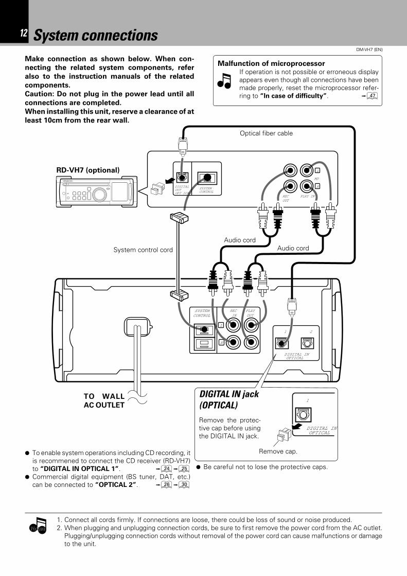
System connectionsMake connection as shown below. When con-
necting the related system components, refer
also to the instruction manuals of the related
components.
Caution: Do not plug in the power lead until all
connections are completed.
When installing this unit, reserve a clearance of at
least 10cm from the rear wall.
1. Connect all cords firmly. If connections are loose, there could be loss of sound or noise produced.2. When plugging and unplugging connection cords, be sure to first remove the power cord from the AC outlet.
Plugging/unplugging connection cords without removal of the power cord can cause malfunctions or damageto the unit.
Malfunction of microprocessorIf operation is not possible or erroneous displayappears even though all connections have beenmade properly, reset the microprocessor refer-ring to “In case of difficulty”. u
¶ To enable system operations including CD recording, itis recommened to connect the CD receiver (RD-VH7)to “DIGITAL IN OPTICAL 1”. ¢∞
¶ Commercial digital equipment (BS tuner, DAT, etc.)can be connected to “OPTICAL 2”. §º
TO WALL
AC OUTLET
System control cord
Optical fiber cable
DIGITAL IN jack(OPTICAL)Remove the protec-tive cap before usingthe DIGITAL IN jack.
Audio cord
RD-VH7 (optional)
Remove cap.
NotesNotes
Audio cord
¶ Be careful not to lose the protective caps.
13System connections
DM-VH7 (EN)
Note on connection of optical-fiber cable
The optical-fiber cable is used in the connection of
the CD receiver (optional RD-VH7). The digital
signal transmission makes it possible to record
the high-quality sound of CDs without degrada-
tion.
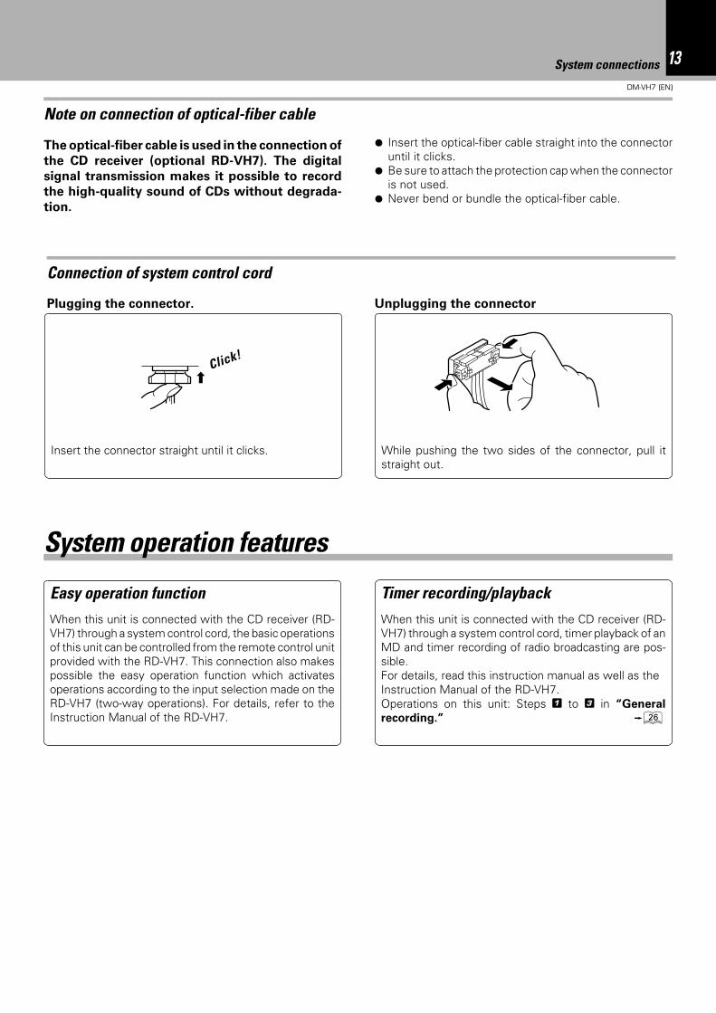
¶ Insert the optical-fiber cable straight into the connectoruntil it clicks.
¶ Be sure to attach the protection cap when the connectoris not used.
¶ Never bend or bundle the optical-fiber cable.
Easy operation functionWhen this unit is connected with the CD receiver (RD-VH7) through a system control cord, the basic operationsof this unit can be controlled from the remote control unitprovided with the RD-VH7. This connection also makespossible the easy operation function which activatesoperations according to the input selection made on theRD-VH7 (two-way operations). For details, refer to theInstruction Manual of the RD-VH7.
Timer recording/playbackWhen this unit is connected with the CD receiver (RD-VH7) through a system control cord, timer playback of anMD and timer recording of radio broadcasting are pos-sible.For details, read this instruction manual as well as theInstruction Manual of the RD-VH7.Operations on this unit: Steps 1 to 3 in “General
recording.” §
System operation features
Insert the connector straight until it clicks.
Plugging the connector. Unplugging the connector
Connection of system control cord
While pushing the two sides of the connector, pull itstraight out.
Click!
14 Names and functions of parts
DM-VH7 (EN)
rec level
recording
eject
standby
enter
stopre
c
o.t.e
.
on
/sta
nd
by
mode
disc loading mechanism
minidisc recorder DM-VH7
20bit A/D&D/A converter
3
#!
021 45 7
@
6 8 9
$
Names and functions of parts
Display/Main unit
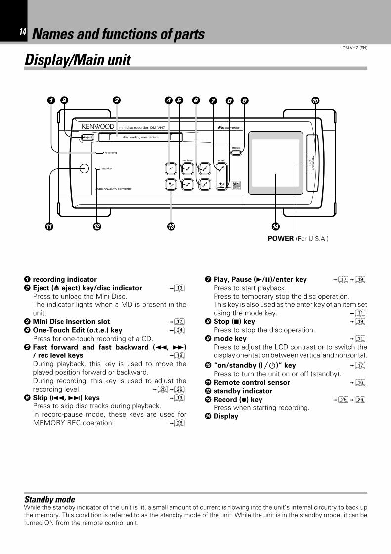
1 recording indicator
2 Eject (0 eject) key/disc indicator (Press to unload the Mini Disc.The indicator lights when a MD is present in theunit.
3 Mini Disc insertion slot &4 One-Touch Edit (o.t.e.) key ¢
Press for one-touch recording of a CD.5 Fast forward and fast backward (1, ¡)
/ rec level keys (During playback, this key is used to move theplayed position forward or backward.During recording, this key is used to adjust therecording level. ∞§
6 Skip (4, ¢) keys (Press to skip disc tracks during playback.In record-pause mode, these keys are used forMEMORY REC operation. •
7 Play, Pause (3/8)/enter key &(Press to start playback.Press to temporary stop the disc operation.This key is also used as the enter key of an item setusing the mode key. !
8 Stop (7) key (Press to stop the disc operation.
9 mode key !Press to adjust the LCD contrast or to switch thedisplay orientation between vertical and horizontal.
0 “on/standby ( )” key &Press to turn the unit on or off (standby).
! Remote control sensor ^@ standby indicator
# Record (¶) key ∞§Press when starting recording.
$ Display
Standby modeWhile the standby indicator of the unit is lit, a small amount of current is flowing into the unit’s internal circuitry to back upthe memory. This condition is referred to as the standby mode of the unit. While the unit is in the standby mode, it can beturned ON from the remote control unit.
POWER (For U.S.A.)
15Names and functions of parts
DM-VH7 (EN)
Remote control unit
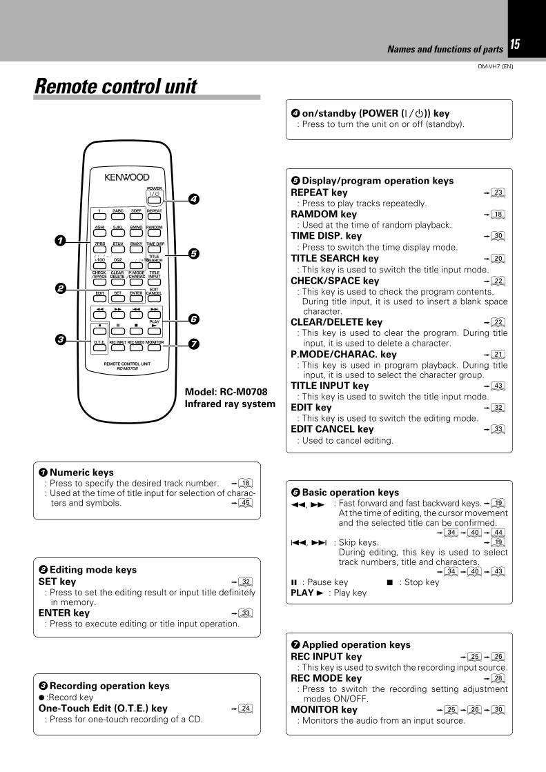
1Numeric keys: Press to specify the desired track number. *: Used at the time of title input for selection of charac-
ters and symbols. t
4on/standby (POWER ( )) key: Press to turn the unit on or off (standby).
2Editing mode keys
SET key ¤: Press to set the editing result or input title definitely
in memory.ENTER key ‹
: Press to execute editing or title input operation.
Model: RC-M0708
Infrared ray system
5Display/program operation keys
REPEAT key £: Press to play tracks repeatedly.
RAMDOM key *: Used at the time of random playback.
TIME DISP. key º: Press to switch the time display mode.
TITLE SEARCH key ): This key is used to switch the title input mode.
CHECK/SPACE key ™: This key is used to check the program contents.
During title input, it is used to insert a blank spacecharacter.
CLEAR/DELETE key ™: This key is used to clear the program. During title
input, it is used to delete a character.P.MODE/CHARAC. key ¡
: This key is used in program playback. During titleinput, it is used to select the character group.
TITLE INPUT key e: This key is used to switch the title input mode.
EDIT key ¤: This key is used to switch the editing mode.
EDIT CANCEL key ‹: Used to cancel editing.
6Basic operation keys
1, ¡ : Fast forward and fast backward keys.(At the time of editing, the cursor movementand the selected title can be confirmed.
›‚r4, ¢ : Skip keys. (
During editing, this key is used to selecttrack numbers, title and characters.
›‚e8 : Pause key 7 : Stop keyPLAY 3 : Play key
2ABC1 3DEF
5JKL 6MNO4GHI
8TUV 9WXY7PRS
EDITCANCEL
0QZ , , : ? +10& ( ) - /+100
RANDOM
REPEAT
CHECK/SPACE
P.MODE/CHARAC.
CLEARDELETE
EDIT SET ENTER
8 7
¡ 1 4 ¢
REC MODE
TIME DISP.
TITLE SEARCH
MONITOR
REMOTE CONTROL UNITRC-M0708
O.T.E.
÷ PLAY£
4
2
5
3
6
7
1
TITLEINPUT
REC INPUT
POWER
3Recording operation keys¶ :Record keyOne-Touch Edit (O.T.E.) key ¢
: Press for one-touch recording of a CD.
7Applied operation keys
REC INPUT key ∞§: This key is used to switch the recording input source.
REC MODE key •: Press to switch the recording setting adjustment
modes ON/OFF.MONITOR key ∞§º
: Monitors the audio from an input source.
16DM-VH7 (EN)
Operation of remote control unit
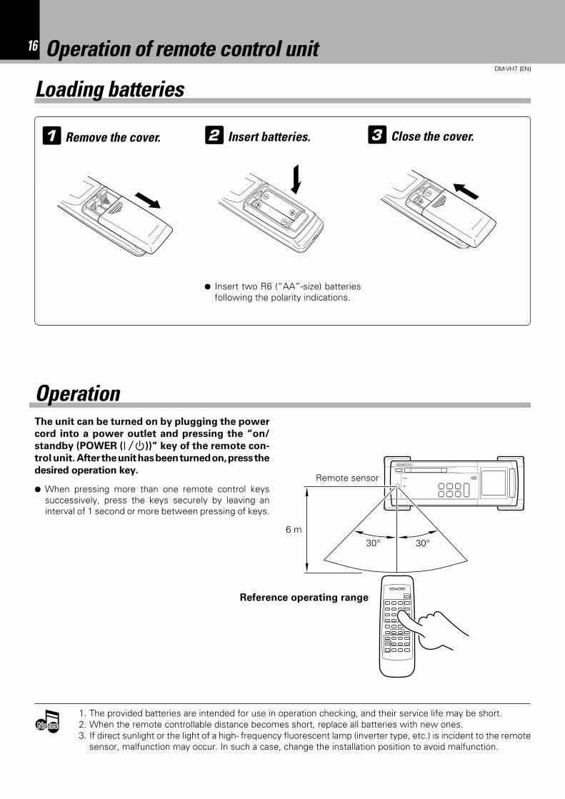
1 Remove the cover. Insert batteries.2 3 Close the cover.
¶ Insert two R6 (“AA”-size) batteriesfollowing the polarity indications.
The unit can be turned on by plugging the power
cord into a power outlet and pressing the “on/
standby (POWER ( ))” key of the remote con-
trol unit. After the unit has been turned on, press the
desired operation key.
Operation
1. The provided batteries are intended for use in operation checking, and their service life may be short.2. When the remote controllable distance becomes short, replace all batteries with new ones.3. If direct sunlight or the light of a high- frequency fluorescent lamp (inverter type, etc.) is incident to the remote
sensor, malfunction may occur. In such a case, change the installation position to avoid malfunction.
NotesNotesNotes
Remote sensor
6 m30° 30°
Reference operating range
¶ When pressing more than one remote control keyssuccessively, press the keys securely by leaving aninterval of 1 second or more between pressing of keys.
Loading batteries
17Playback of Mini Disc
DM-VH7 (EN)
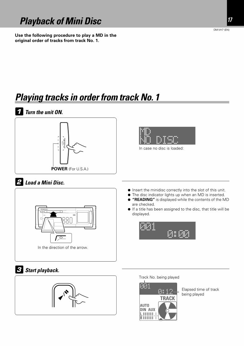
Use the following procedure to play a MD in the
original order of tracks from track No. 1.
1 Turn the unit ON.
Playback of Mini Disc
Playing tracks in order from track No. 1
3 Start playback.
2 Load a Mini Disc.¶ Insert the minidisc correctly into the slot of this unit.¶ The disc indicator lights up when an MD is inserted.¶ “READING” is displayed while the contents of the MD
are checked.¶ If a title has been assigned to the disc, that title will be
displayed.
Elapsed time of trackbeing played
In the direction of the arrow.
In case no disc is loaded:
POWER (For U.S.A.)
on
/sta
nd
by
Track No. being played
NO DISCMD
0:00001
0:12001
TITLER
AUTODINoAUXLR
TRACK
18 Playback of Mini Disc
DM-VH7 (EN)
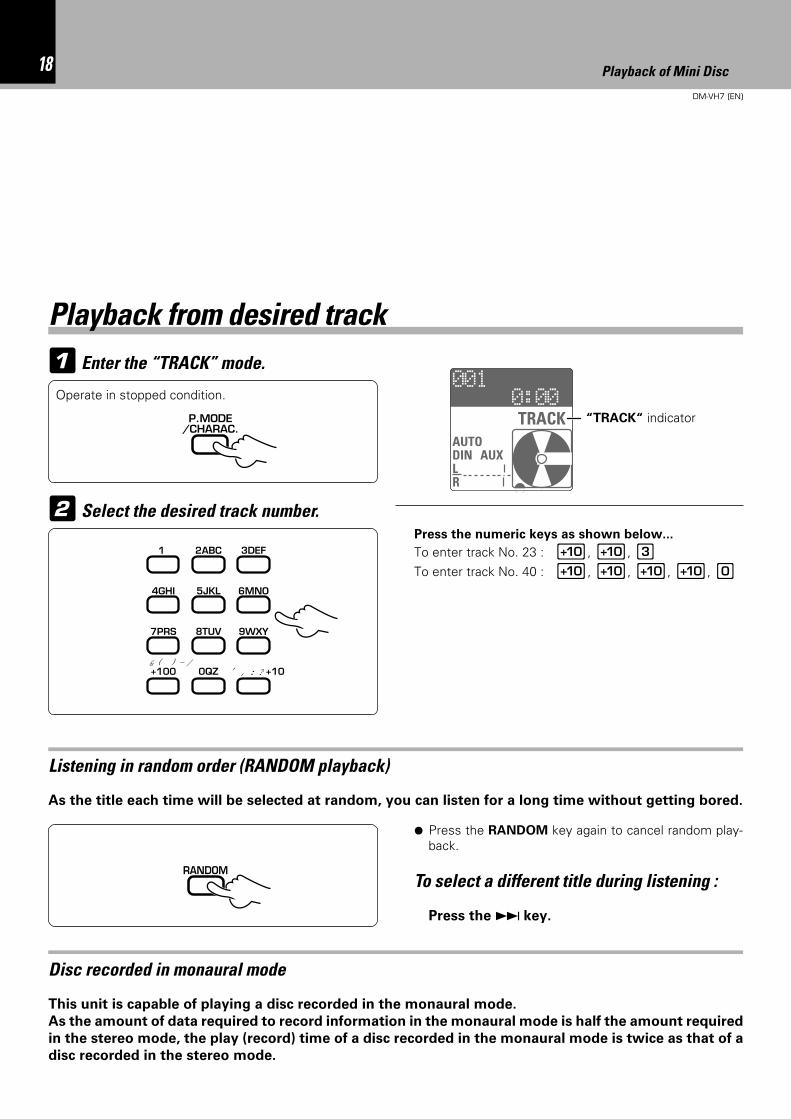
1 Enter the “TRACK” mode.
Playback from desired track
2 Select the desired track number.Press the numeric keys as shown below...
To enter track No. 23 : 0, 0, 3To enter track No. 40 : 0, 0, 0, 0, )
“TRACK“ indicator
Disc recorded in monaural mode
This unit is capable of playing a disc recorded in the monaural mode.
As the amount of data required to record information in the monaural mode is half the amount required
in the stereo mode, the play (record) time of a disc recorded in the monaural mode is twice as that of a
disc recorded in the stereo mode.
Operate in stopped condition.
Listening in random order (RANDOM playback)
As the title each time will be selected at random, you can listen for a long time without getting bored.
To select a different title during listening :
Press the ¢ key.
P.MODE/CHARAC.
2ABC1 3DEF
5JKL 6MNO4GHI
8TUV 9WXY7PRS
0QZ ,, : ? +10
& ( ) - /+100
RANDOM
¶ Press the RANDOM key again to cancel random play-back.
0:00001
TITLER
AUTODINOAUXLR
TRACK
19Playback of Mini Disc
DM-VH7 (EN)
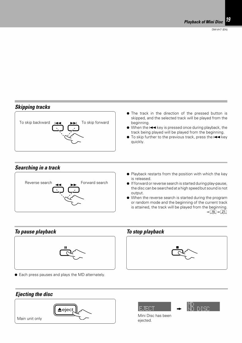
Searching in a track
Skipping tracks
Ejecting the disc
¶ Playback restarts from the position with which the keyis released.
¶ If forward or reverse search is started during play-pause,the disc can be searched at a high speed but sound is notoutput.
¶ When the reverse search is started during the programor random mode and the beginning of the current trackis attained, the track will be played from the beginning.
*¡
¶ The track in the direction of the pressed button isskipped, and the selected track will be played from thebeginning.
¶ When the 4 key is pressed once during playback, thetrack being played will be played from the beginning.
¶ To skip further to the previous track, press the 4 keyquickly.
To pause playback
¶ Each press pauses and plays the MD alternately.
To stop playback
Main unit only
Forward searchReverse search
To skip forwardTo skip backward
Mini Disc has beenejected.
4 ¢
¡ 1
8 7
eject EJECT NO DISCMD
20 Playback of Mini Disc
DM-VH7 (EN)
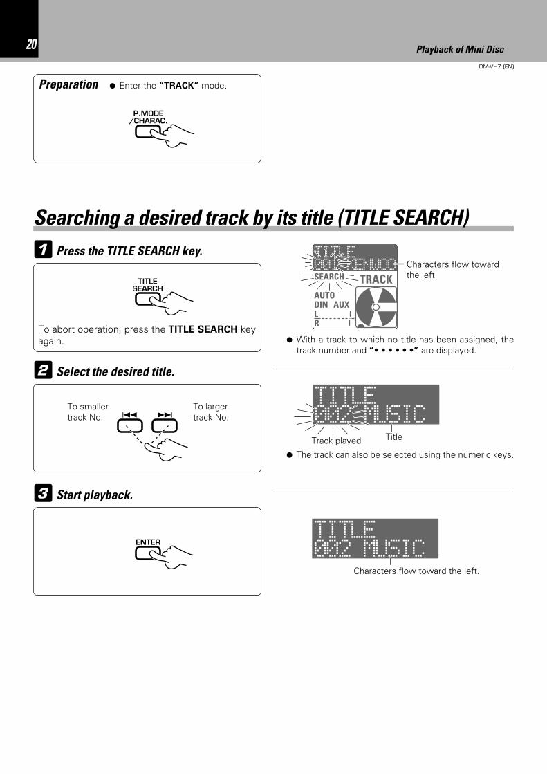
1 Press the TITLE SEARCH key.
2 Select the desired title.
3 Start playback.
¶ With a track to which no title has been assigned, thetrack number and “• • • • • •” are displayed.
Preparation
To smallertrack No.
To largertrack No.
To abort operation, press the TITLE SEARCH keyagain.
Characters flow towardthe left.
Characters flow toward the left.
Track played
¶ Enter the “TRACK” mode.
Title
Searching a desired track by its title (TITLE SEARCH)
P.MODE/CHARAC.
TITLESEARCH
4 ¢
¶ The track can also be selected using the numeric keys.
ENTER
TITLE
SEARCH
AUTODINOAUXLR
TRACK001 KENWOO
TITLE002 MUSIC
TITLE002 MUSIC
21Programming
DM-VH7 (EN)
Programming
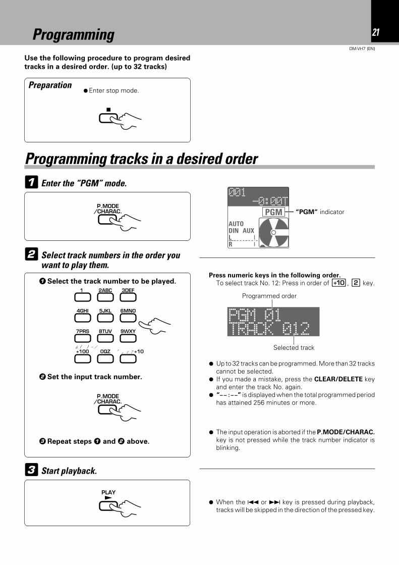
1 Enter the “PGM” mode.
Use the following procedure to program desired
tracks in a desired order. (up to 32 tracks)
Preparation¶Enter stop mode.
¶ Up to 32 tracks can be programmed. More than 32 trackscannot be selected.
¶ If you made a mistake, press the CLEAR/DELETE keyand enter the track No. again.
¶ “– – : – –” is displayed when the total programmed periodhas attained 256 minutes or more.
Programming tracks in a desired order
3 Start playback.
¶ When the 4 or ¢ key is pressed during playback,tracks will be skipped in the direction of the pressed key.
¶ The input operation is aborted if the P.MODE/CHARAC.
key is not pressed while the track number indicator isblinking.
Press numeric keys in the following order.
To select track No. 12: Press in order of 0, 2 key.1Select the track number to be played.
“PGM” indicator
2Set the input track number.
Selected track
Programmed order
2 Select track numbers in the order youwant to play them.
3Repeat steps 1 and 2 above.
7
P.MODE/CHARAC.
2ABC1 3DEF
5JKL 6MNO4GHI
8TUV 9WXY7PRS
0QZ ,, : ? +10
& ( ) - /+100
P.MODE/CHARAC.
PLAY£
-0:00T001
TITLER
AUTODINOAUXLR
PGM
TRACK 012PGM 01
22 Programming
DM-VH7 (EN)
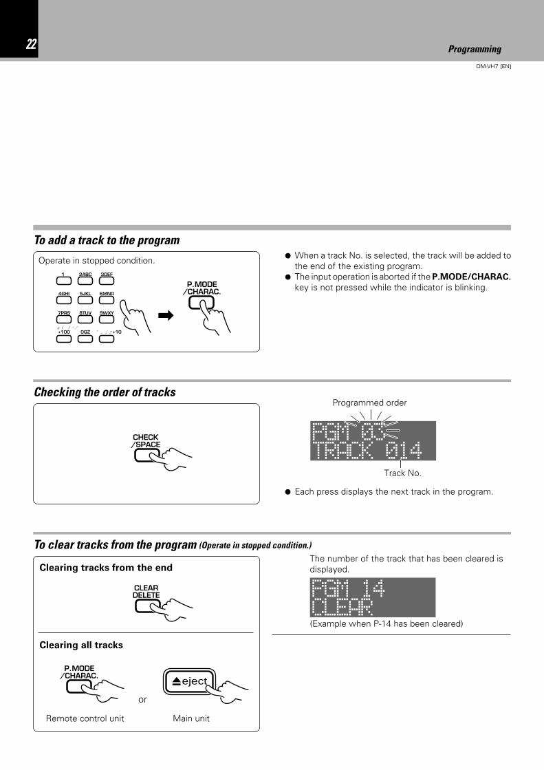
To add a track to the program¶ When a track No. is selected, the track will be added to
the end of the existing program.¶ The input operation is aborted if the P.MODE/CHARAC.
key is not pressed while the indicator is blinking.
To clear tracks from the program (Operate in stopped condition.)
Clearing all tracks
Clearing tracks from the end
Checking the order of tracks
¶ Each press displays the next track in the program.
or
Main unitRemote control unit
(Example when P-14 has been cleared)
Programmed order
Track No.
Operate in stopped condition.
P.MODE/CHARAC.
2ABC1 3DEF
5JKL 6MNO4GHI
8TUV 9WXY7PRS
0QZ ,, : ? +10
& ( ) - /+100
\
CHECK/SPACE
CLEARDELETE
P.MODE/CHARAC.
eject
The number of the track that has been cleared isdisplayed.
PGM 03TRACK 014
PGM 14CLEAR
23Programming
DM-VH7 (EN)
To repeat only the programmed tracks
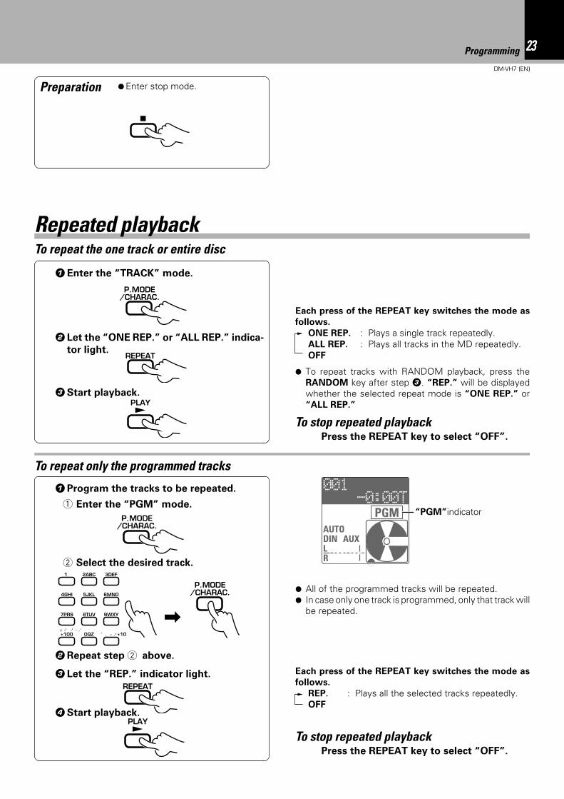
To repeat the one track or entire disc
1Program the tracks to be repeated.
1 Enter the “PGM” mode.
4Start playback.
2 Select the desired track.
3 Let the “REP.” indicator light.
To stop repeated playbackPress the REPEAT key to select “OFF”.
Repeated playback
1Enter the “TRACK” mode.
2 Let the “ONE REP.” or “ALL REP.” indica-
tor light.
3Start playback.
To stop repeated playbackPress the REPEAT key to select “OFF”.
Preparation ¶Enter stop mode.
¶ All of the programmed tracks will be repeated.¶ In case only one track is programmed, only that track will
be repeated.
“PGM”indicator
2Repeat step 2 above.
7
P.MODE/CHARAC.
P.MODE/CHARAC.
2ABC1 3DEF
5JKL 6MNO4GHI
8TUV 9WXY7PRS
0QZ ,, : ? +10
& ( ) - /+100
\
REPEAT
PLAY£
P.MODE/CHARAC.
REPEAT
PLAY£
Each press of the REPEAT key switches the mode as
follows.
REP. : Plays all the selected tracks repeatedly.OFF
Each press of the REPEAT key switches the mode as
follows.
ONE REP. : Plays a single track repeatedly.ALL REP. : Plays all tracks in the MD repeatedly.OFF
¶ To repeat tracks with RANDOM playback, press theRANDOM key after step 3. “REP.” will be displayedwhether the selected repeat mode is “ONE REP.” or“ALL REP.”
-0:00T001
AUTODIN AUXLR
PGM
24DM-VH7 (EN)
When this unit is connected with the CD receiver (RD-VH7) through a system control cord, desired tracks
can be selected while playing a CD and recorded automatically onto an MD. This function is referred to
as O.T.E. (One Touch Edit). The synchronized recording with CD also possible in this configuration.
2
Press the stop (7) key to stop recording in the middle.
Press the O.T.E. key.
Stop CD playback.
Press the O.T.E. key.
Preparation
Play the track to be recorded.
¶ When the O.T.E. key is pressed during CD playback, thetrack being played will be replayed from the beginningand only this track will be recorded.
¶ After the track has been recorded, the MD recorderstops and the CD player enters pause mode.
¶ With O.T.E. recording, the recording input is automati-cally set to DIN CD (digital) and the recording level isautomatically set to 0 dB.
¶ It is not possible to change the recording input orrecording level during O.T.E. recording.
÷ Connect the digital output of the CD receiver toDIGITAL 1 input of the MD recorder. @
÷ Select the CD input on the CD receiver.÷ Load a recordable MD in the MD recorder. 8
Recording all tracks on a CD (O.T.E.)
Recording a single CD track (O.T.E.)
O.T.E.
O.T.E.
Systematized recording features
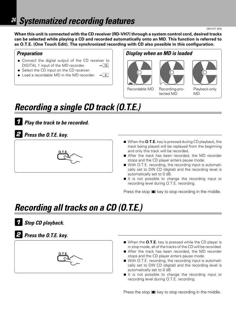
Display when an MD is loaded
Recordable MD Recording-pro-tected MD
Playback-onlyMD
1
2
Press the stop (7) key to stop recording in the middle.
¶ When the O.T.E. key is pressed while the CD player isin stop mode, all of the tracks of the CD will be recorded.
¶ After the track has been recorded, the MD recorderstops and the CD player enters pause mode.
¶ With O.T.E. recording, the recording input is automati-cally set to DIN CD (digital) and the recording level isautomatically set to 0 dB.
¶ It is not possible to change the recording input orrecording level during O.T.E. recording.
1
25DM-VH7 (EN)
When this unit is connected with the CD receiver (RD-VH7) through a system control cord, recording (MD)
and playback (CD) can be started simultaneously so that playback sound can be recorded without the loss
of any part.
1 Select the REC INPUT.
REC INPUT
¶ Select “DIN CD” for recording a digital input or “ANA-
LOG” for recording an analog input.
Put the MD recorder in record-pause mode.4
÷
Play the CD player.5
Preparation
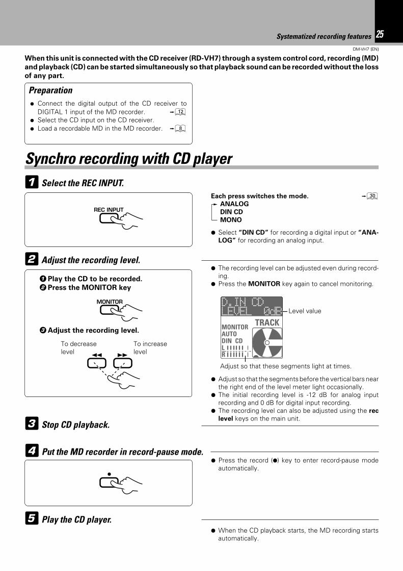
Adjust the recording level.21Play the CD to be recorded.
2Press the MONITOR key
To decreaselevel
To increaselevel
3Adjust the recording level.
MONITOR
¡ 1
¶ The recording level can be adjusted even during record-ing.
¶ Press the MONITOR key again to cancel monitoring.
Level value
¶ Adjust so that the segments before the vertical bars nearthe right end of the level meter light occasionally.
¶ The initial recording level is -12 dB for analog inputrecording and 0 dB for digital input recording.
¶ The recording level can also be adjusted using the rec
level keys on the main unit.
Adjust so that these segments light at times.
Stop CD playback.3
¶ When the CD playback starts, the MD recording startsautomatically.
¶ Press the record (¶) key to enter record-pause modeautomatically.
Systematized recording features
Synchro recording with CD player
Each press switches the mode. ºANALOG
DIN CD
MONO
÷ Connect the digital output of the CD receiver toDIGITAL 1 input of the MD recorder. @
÷ Select the CD input on the CD receiver.÷ Load a recordable MD in the MD recorder. 8
LEVEL 0dBD.IN CD
MONITORAUTODIN CDLR
TRACK
26DM-VH7 (EN)
The input jacks connected with audio cords accept analog signals. This unit records the analog signal from the
REC IN jacks by converting it into digital signal. (This recording is simply referred to as analog recording.)
When this unit and CD player are connected with an optical fiber cable, the digital signal input through
the DIGITAL IN (OPTICAL) jack can be recorded in a digital form (this recording is hereinafter referred to
as digital recording). Enjoy high sound quality of digital recording.
Preparation
General recording
÷ Open the write protect tab of theMini Disc to make it recordable.
8÷ Check the remaining recording time.
º
Select the REC INPUT.2
Adjust the recording level.31Play the source to be recorded.
(This operation is not required when re-
cording radio broadcasting.)
2Press the MONITOR key
REC INPUT
To decreaselevel
To increaselevel
3Adjust the recording level.
MONITOR
¡ 1
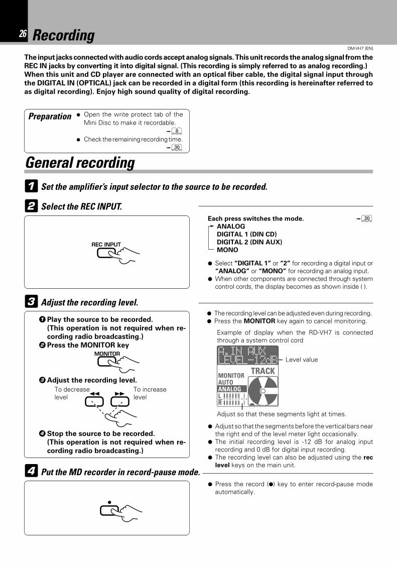
¶ The recording level can be adjusted even during recording.¶ Press the MONITOR key again to cancel monitoring.
Level value
¶ Adjust so that the segments before the vertical bars nearthe right end of the level meter light occasionally.
¶ The initial recording level is -12 dB for analog inputrecording and 0 dB for digital input recording.
¶ The recording level can also be adjusted using the rec
level keys on the main unit.
Adjust so that these segments light at times.
¶ Press the record (¶) key to enter record-pause modeautomatically.
Put the MD recorder in record-pause mode.4
÷
Recording
Set the amplifier’s input selector to the source to be recorded.1
Each press switches the mode. ºANALOG
DIGITAL 1 (DIN CD)
DIGITAL 2 (DIN AUX)
MONO
¶ Select “DIGITAL 1” or “2” for recording a digital input or“ANALOG” or “MONO” for recording an analog input.
¶ When other components are connected through systemcontrol cords, the display becomes as shown inside ( ).
Example of display when the RD-VH7 is connectedthrough a system control cord
4Stop the source to be recorded.
(This operation is not required when re-
cording radio broadcasting.)
LEVEL-12dBA.IN AUX
MONITORAUTOANALOGLR
TRACK
27DM-VH7 (EN)
Recording is not possible if the following characters aredisplayed.“DISC FULL” : Disc is full
\Erase undesired tracks. ‚“PROTECTED” : The accidental erasure protect tab is open.
\ Close it. 8“PLAY ONLY” : A playback-only Mini Disc is loaded.
\ Load a recordable Mini Disc.
Digital recording is not possible if the following charactersare displayed.“UNLOCK” : The sampling frequency is not 32 kHz, 44.1
kHz, 48kHz. ª\Use analog recording. ∞§
: The optical fiber cable is unplugged or loos-ened. (The connector is not connected.)\Connect the optical fiber cable correctly.
@#“SCMS” : Digital recording is prohibited by SCMS.
ª\Use analog recording. ∞§
“NOT AUDIO” : The input digital signal is not an audiosignal.
Start recording.
¶ When the EDIT key is pressed during recording, a tracknumber is inserted in that position.
¶ Recording can also be started by pressing the 8 or 6key.
5
Play the source to be recorded.(This operation is not required when recording radio broadcasting.)
6
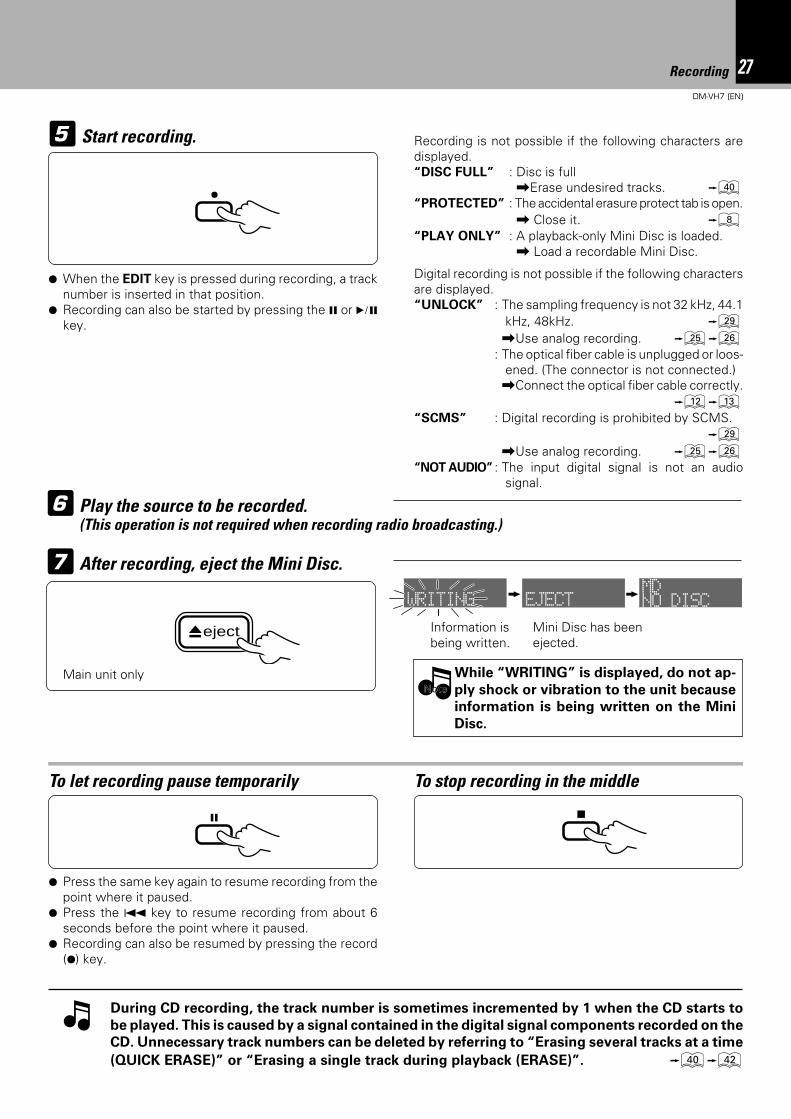
After recording, eject the Mini Disc.7
eject Mini Disc has beenejected.
Information isbeing written.
Main unit only
To stop recording in the middleTo let recording pause temporarily
78
¶ Press the same key again to resume recording from thepoint where it paused.
¶ Press the 4 key to resume recording from about 6seconds before the point where it paused.
¶ Recording can also be resumed by pressing the record(¶) key.
During CD recording, the track number is sometimes incremented by 1 when the CD starts to
be played. This is caused by a signal contained in the digital signal components recorded on the
CD. Unnecessary track numbers can be deleted by referring to “Erasing several tracks at a time
(QUICK ERASE)” or “Erasing a single track during playback (ERASE)”. ‚w
Recording
While “WRITING” is displayed, do not ap-
ply shock or vibration to the unit because
information is being written on the Mini
Disc.
NoteNote
÷
WRITING EJECT NO DISCMD
28DM-VH7 (EN)
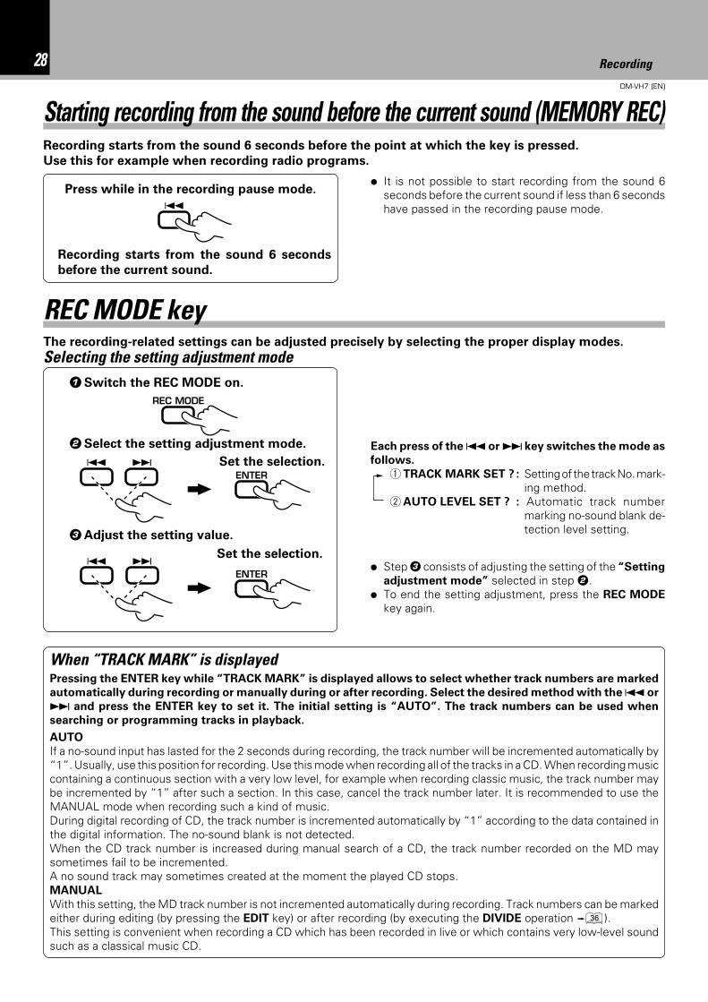
Starting recording from the sound before the current sound (MEMORY REC)Recording starts from the sound 6 seconds before the point at which the key is pressed.
Use this for example when recording radio programs.
Press while in the recording pause mode.
Recording starts from the sound 6 seconds
before the current sound.
÷ It is not possible to start recording from the sound 6seconds before the current sound if less than 6 secondshave passed in the recording pause mode.4
Each press of the 4 or ¢ key switches the mode as
follows.
1 TRACK MARK SET ? : Setting of the track No. mark-ing method.
2 AUTO LEVEL SET ? : Automatic track numbermarking no-sound blank de-tection level setting.
1Switch the REC MODE on.
2Select the setting adjustment mode.
3Adjust the setting value.
The recording-related settings can be adjusted precisely by selecting the proper display modes.
÷ Step 3 consists of adjusting the setting of the “Setting
adjustment mode” selected in step 2.÷ To end the setting adjustment, press the REC MODE
key again.
Selecting the setting adjustment mode
REC MODE key
Set the selection.
Set the selection.
REC MODE
4 ¢ ENTER
4 ¢ ENTER
Recording
When “TRACK MARK” is displayedPressing the ENTER key while “TRACK MARK” is displayed allows to select whether track numbers are marked
automatically during recording or manually during or after recording. Select the desired method with the 4 or
¢ and press the ENTER key to set it. The initial setting is “AUTO”. The track numbers can be used when
searching or programming tracks in playback.
AUTO
If a no-sound input has lasted for the 2 seconds during recording, the track number will be incremented automatically by“1”. Usually, use this position for recording. Use this mode when recording all of the tracks in a CD. When recording musiccontaining a continuous section with a very low level, for example when recording classic music, the track number maybe incremented by “1” after such a section. In this case, cancel the track number later. It is recommended to use theMANUAL mode when recording such a kind of music.During digital recording of CD, the track number is incremented automatically by “1” according to the data contained inthe digital information. The no-sound blank is not detected.When the CD track number is increased during manual search of a CD, the track number recorded on the MD maysometimes fail to be incremented.A no sound track may sometimes created at the moment the played CD stops.MANUAL
With this setting, the MD track number is not incremented automatically during recording. Track numbers can be markedeither during editing (by pressing the EDIT key) or after recording (by executing the DIVIDE operation fl).This setting is convenient when recording a CD which has been recorded in live or which contains very low-level soundsuch as a classical music CD.
29DM-VH7 (EN)
Recording
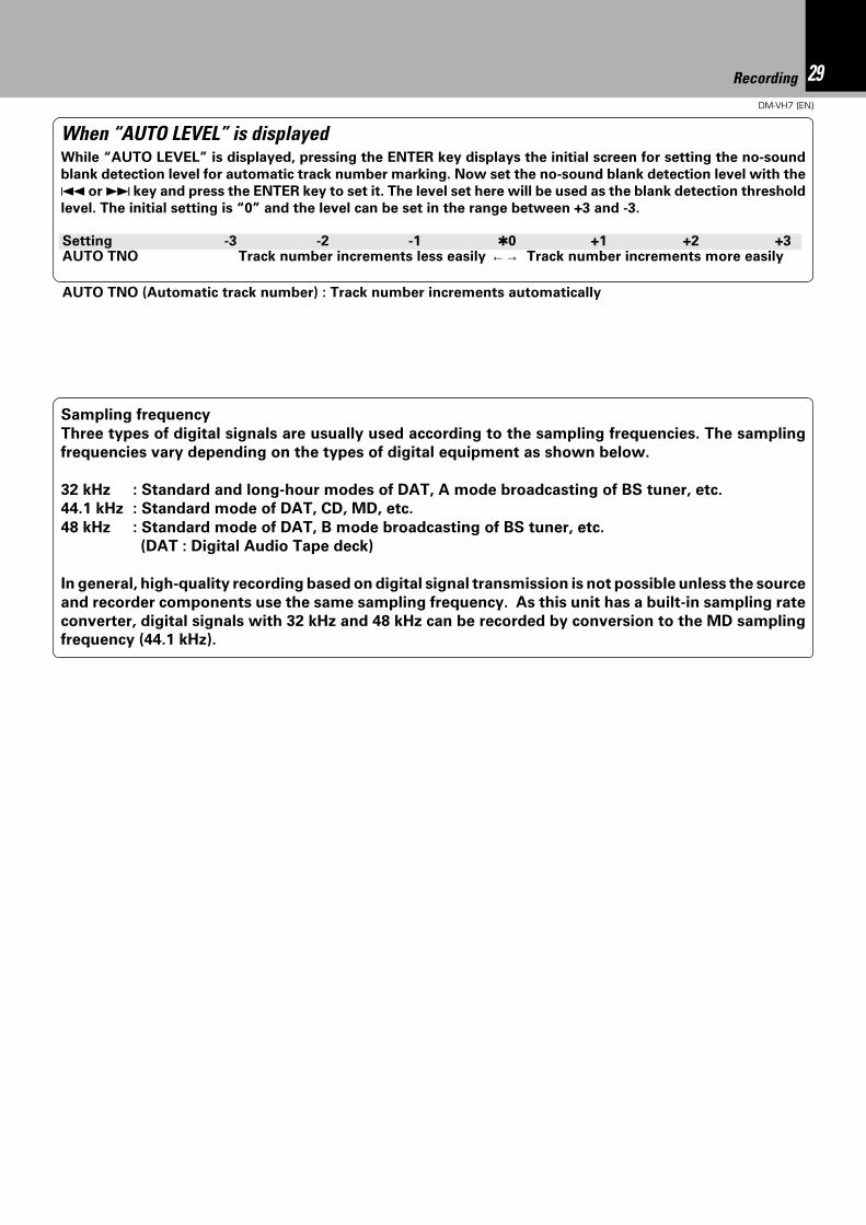
Sampling frequency
Three types of digital signals are usually used according to the sampling frequencies. The sampling
frequencies vary depending on the types of digital equipment as shown below.
32 kHz : Standard and long-hour modes of DAT, A mode broadcasting of BS tuner, etc.
44.1 kHz : Standard mode of DAT, CD, MD, etc.
48 kHz : Standard mode of DAT, B mode broadcasting of BS tuner, etc.
(DAT : Digital Audio Tape deck)
In general, high-quality recording based on digital signal transmission is not possible unless the source
and recorder components use the same sampling frequency. As this unit has a built-in sampling rate
converter, digital signals with 32 kHz and 48 kHz can be recorded by conversion to the MD sampling
frequency (44.1 kHz).
When “AUTO LEVEL” is displayedWhile “AUTO LEVEL” is displayed, pressing the ENTER key displays the initial screen for setting the no-sound
blank detection level for automatic track number marking. Now set the no-sound blank detection level with the
4 or ¢ key and press the ENTER key to set it. The level set here will be used as the blank detection threshold
level. The initial setting is “0” and the level can be set in the range between +3 and -3.
AUTO TNO (Automatic track number) : Track number increments automatically
Setting -3 -2 -1 0 +1 +2 +3AUTO TNO Track number increments less easily ←→ Track number increments more easily
30DM-VH7 (EN)
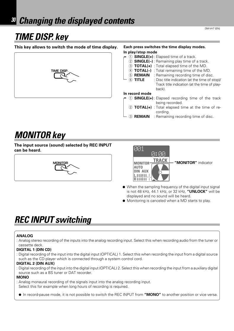
TIME DISP. keyIn play/stop mode
1 SINGLE(+) : Elapsed time of a track.2 SINGLE(–) : Remaining play time of a track.3 TOTAL(+) : Total elapsed time of the MD.4 TOTAL(–) : Total remaining time of the MD.5 REMAIN : Remaining recording time of disc.6 TITLE : Disc title indication (at the time of stop)/
Track title indication (at the time of play-back).
In record mode
1 SINGLE(+) : Elapsed recording time of the trackbeing recorded.
2 TOTAL(+) : Total elapsed time at the time of re-cording.
3 REMAIN : Remaining recording time of disc.
Each press switches the time display modes.This key allows to switch the mode of time display.
TIME DISP.
MONITOR key
¶ When the sampling frequency of the digital input signalis not 48 kHz, 44.1 kHz, or 32 kHz, “UNLOCK” will bedisplayed and no sound will be heard.
¶ Monitoring is canceled when a MD starts to play.
“MONITOR” indicator
The input source (sound) selected by REC INPUT
can be heard.
MONITOR
Changing the displayed contents
ANALOG
: Analog stereo recording of the inputs into the analog recording input. Select this when recording audio from the tuner orcassette deck.
DIGITAL 1 (DIN CD)
: Digital recording of the input into the digital input (OPTICAL) 1. Select this when recording the input from a digital sourcesuch as the CD player which is connected through a system control cord.
DIGITAL 2 (DIN AUX)
: Digital recording of the input into the digital input (OPTICAL) 2. Select this when recording the input from a auxiliary digitalsource such as a BS tuner or DAT recorder.
MONO
: Analog monaural recording of the signals input into the analog recording input.Select this for example when long hours of recording is required.
REC INPUT switching
¶ In record-pause mode, it is not possible to switch the REC INPUT from “MONO” to another position or vice versa.
0:00001
MONITORAUTODIN AUXLR
TRACK
31Editing
DM-VH7 (EN)
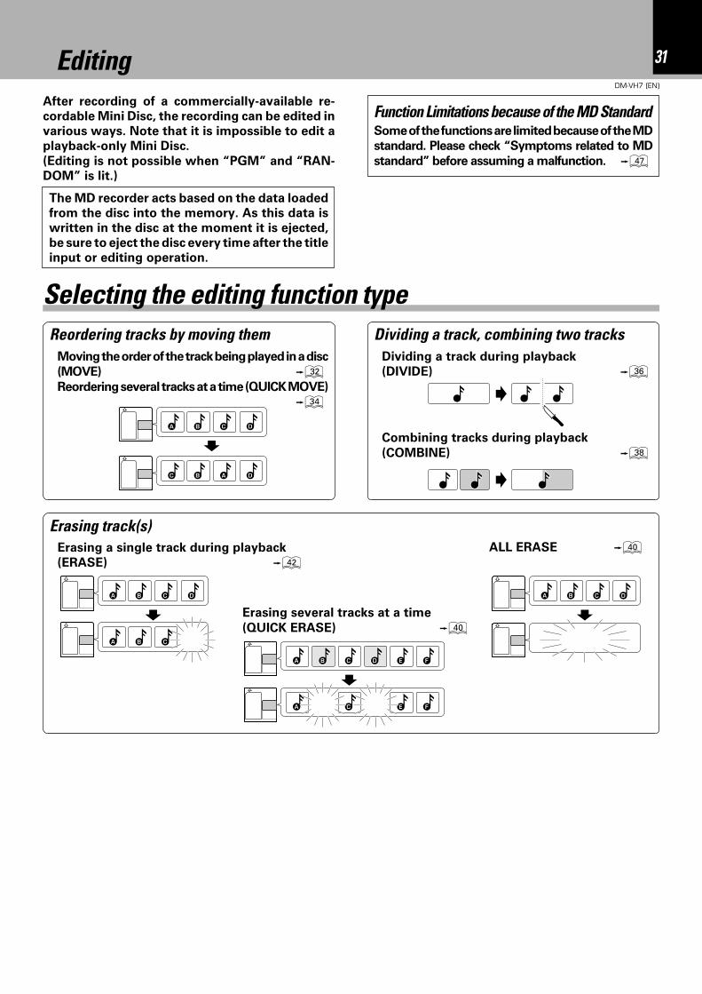
EditingAfter recording of a commercially-available re-
cordable Mini Disc, the recording can be edited in
various ways. Note that it is impossible to edit a
playback-only Mini Disc.
(Editing is not possible when “PGM” and “RAN-
DOM” is lit.)
Selecting the editing function typeReordering tracks by moving them Dividing a track, combining two tracks
Moving the order of the track being played in a disc
(MOVE) ¤Reordering several tracks at a time (QUICK MOVE)
›
DCBA
DABC
Dividing a track during playback
(DIVIDE) fl
Erasing track(s)Erasing a single track during playback
(ERASE) wALL ERASE ‚
DCBA
CBA
Combining tracks during playback
(COMBINE) °
Some of the functions are limited because of the MD
standard. Please check “Symptoms related to MD
standard” before assuming a malfunction. u
Function Limitations because of the MD Standard
DCBA
CBA ED F
E FCA
Erasing several tracks at a time
(QUICK ERASE) ‚
The MD recorder acts based on the data loaded
from the disc into the memory. As this data is
written in the disc at the moment it is ejected,
be sure to eject the disc every time after the title
input or editing operation.
32 Editing
DM-VH7 (EN)
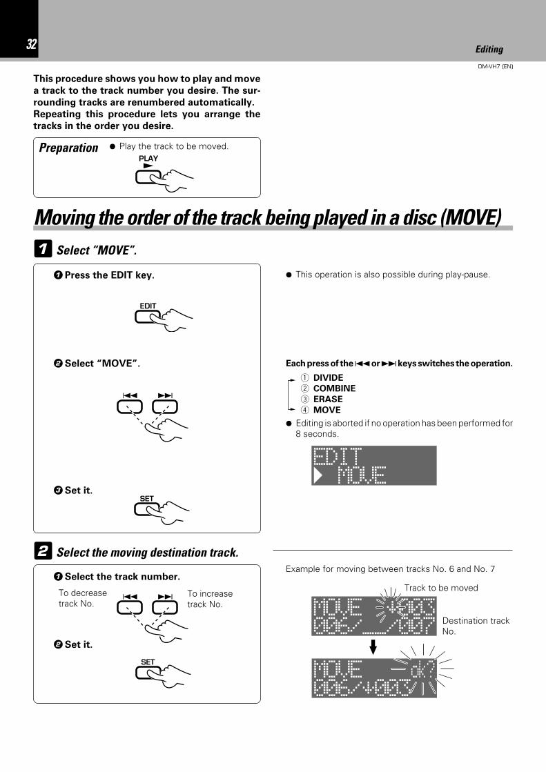
1 Select “MOVE”.
This procedure shows you how to play and move
a track to the track number you desire. The sur-
rounding tracks are renumbered automatically.
Repeating this procedure lets you arrange the
tracks in the order you desire.
2 Select the moving destination track.
1Select the track number.
2Set it.
1Press the EDIT key.
3Set it.
To increasetrack No.
To decreasetrack No.
Destination trackNo.
Track to be moved
¶ Editing is aborted if no operation has been performed for8 seconds.
Each press of the 4 or ¢ keys switches the operation.
1 DIVIDE
2 COMBINE
3 ERASE
4 MOVE
Preparation ¶ Play the track to be moved.
Moving the order of the track being played in a disc (MOVE)
2Select “MOVE”.
PLAY£
EDIT
4 ¢
SET
4 ¢
SET
Example for moving between tracks No. 6 and No. 7
¶ This operation is also possible during play-pause.
MOVEEDIT
006/__/007MOVE –003
006/–003MOVE ok?
33Editing
DM-VH7 (EN)
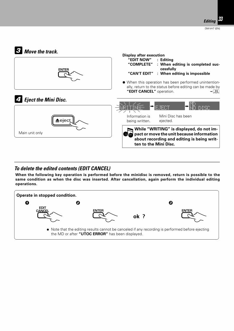
3Move the track.
Eject the Mini Disc.
While “WRITING” is displayed, do not im-
pact or move the unit because information
about recording and editing is being writ-
ten to the Mini Disc.
Information isbeing written.
Mini Disc has beenejected.
4
Display after execution
“EDIT NOW” : Editing
“COMPLETE” : When editing is completed suc-
cessfully
“CAN'T EDIT” : When editing is impossible
NoteNote
¶ When this operation has been performed unintention-ally, return to the status before editing can be made by“EDIT CANCEL” operation. ‹
To delete the edited contents (EDIT CANCEL)When the following key operation is performed before the minidisc is removed, return is possible to the
same condition as when the disc was inserted. After cancellation, again perform the individual editing
operations.
1
Operate in stopped condition.
2 3
ok ?
ENTER
EDITCANCEL ENTER ENTER
Main unit only
÷ Note that the editing results cannot be canceled if any recording is performed before ejectingthe MD or after “UTOC ERROR” has been displayed.
eject
WRITING EJECT NO DISCMD
34 Editing
DM-VH7 (EN)
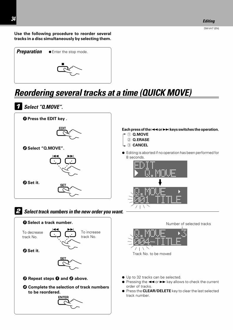
1 Select “Q.MOVE”.
Reordering several tracks at a time (QUICK MOVE)
Use the following procedure to reorder several
tracks in a disc simultaneously by selecting them.
Preparation ¶Enter the stop mode.
2 Select track numbers in the new order you want.
1Select a track number.
2Set it.
To decreasetrack No.
To increasetrack No.
3 Repeat steps 1 and 2 above. ¶ Up to 32 tracks can be selected.¶ Pressing the 1 or ¡ key allows to check the current
order of tracks.¶ Press the CLEAR/DELETE key to clear the last selected
track number.
Track No. to be moved
Number of selected tracks
2Select “Q.MOVE”.
3Set it.
1Press the EDIT key .
¶ Editing is aborted if no operation has been performed for8 seconds.
Each press of the 4 or ¢ keys switches the operation.
1 Q.MOVE
2 Q.ERASE
3 CANCEL
4 Complete the selection of track numbers
to be reordered.
7
EDIT
4 ¢
SET
4 ¢
SET
ENTER
Q.MOVEEDIT
001 TITLEQ.MOVE
004 TITLEQ.MOVE 3
35Editing
DM-VH7 (EN)
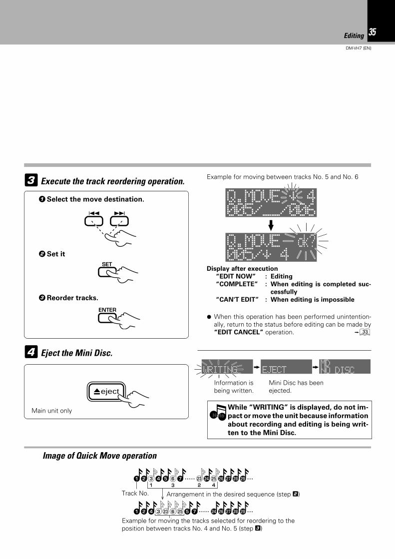
3 Execute the track reordering operation.
11 3 2 4
2 3 4 5 6 7 25 26 27 28 2923 24
1 2 4 3 23 6 24 26 27 28 295 725
Image of Quick Move operation
Track No. Arrangement in the desired sequence (step 2)
Display after execution
“EDIT NOW” : Editing
“COMPLETE” : When editing is completed suc-
cessfully
“CAN'T EDIT” : When editing is impossible
Eject the Mini Disc.
While “WRITING” is displayed, do not im-
pact or move the unit because information
about recording and editing is being writ-
ten to the Mini Disc.
Information isbeing written.
Mini Disc has beenejected.
4
NoteNote
1Select the move destination.
3Reorder tracks.
2Set it
¶ When this operation has been performed unintention-ally, return to the status before editing can be made by“EDIT CANCEL” operation. ‹
Example for moving between tracks No. 5 and No. 6
Example for moving the tracks selected for reordering to theposition between tracks No. 4 and No. 5 (step 3)
4 ¢
SET
ENTER
Main unit only
eject
005/__/006Q.MOVE – 4
005/– 4Q.MOVE ok?
WRITING EJECT NO DISCMD
36 Editing
DM-VH7 (EN)
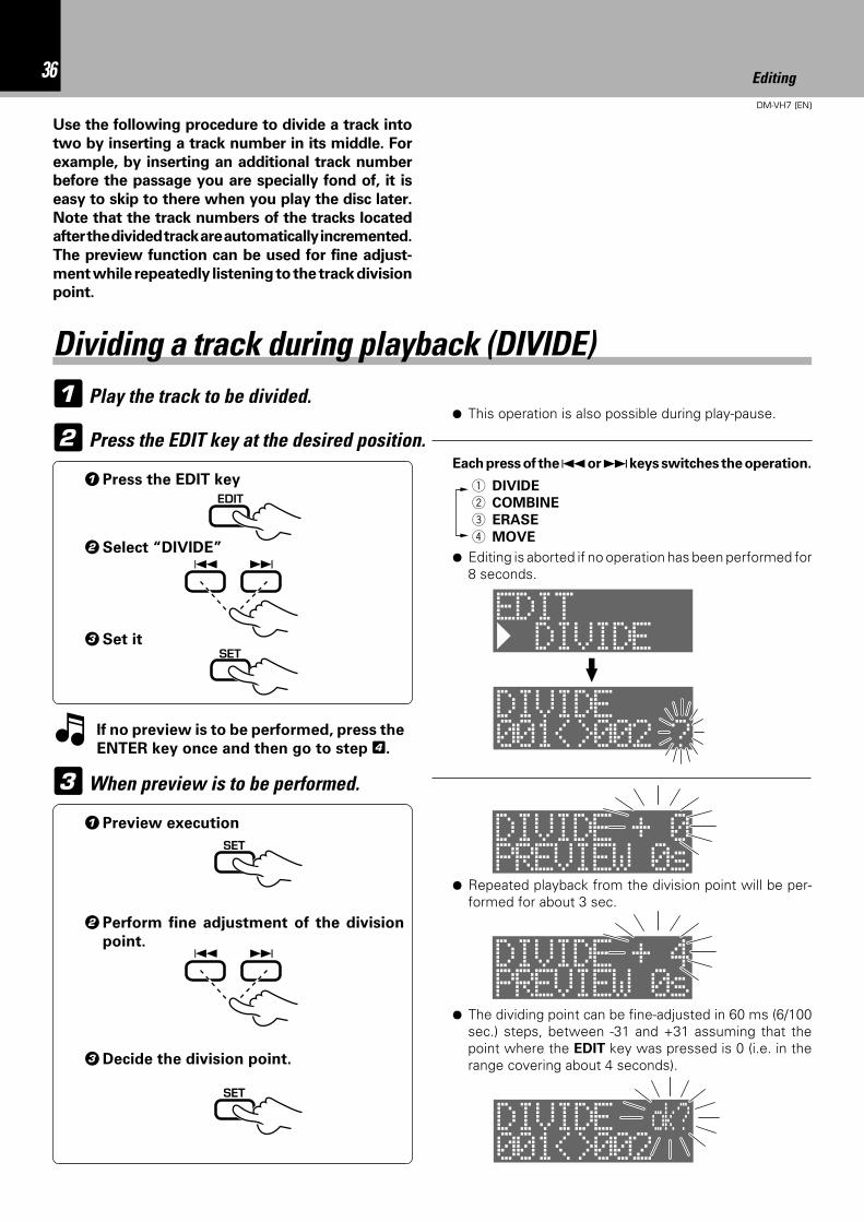
1 Play the track to be divided.
Use the following procedure to divide a track into
two by inserting a track number in its middle. For
example, by inserting an additional track number
before the passage you are specially fond of, it is
easy to skip to there when you play the disc later.
Note that the track numbers of the tracks located
after the divided track are automatically incremented.
The preview function can be used for fine adjust-
ment while repeatedly listening to the track division
point.
3When preview is to be performed.
2 Press the EDIT key at the desired position.Each press of the 4 or ¢ keys switches the operation.
¶ Editing is aborted if no operation has been performed for8 seconds.
1 DIVIDE
2 COMBINE
3 ERASE
4 MOVE
¶ This operation is also possible during play-pause.
Dividing a track during playback (DIVIDE)
1Press the EDIT key
If no preview is to be performed, press the
ENTER key once and then go to step 4.
1Preview execution
2Perform fine adjustment of the division
point.
3Decide the division point.
¶ Repeated playback from the division point will be per-formed for about 3 sec.
¶ The dividing point can be fine-adjusted in 60 ms (6/100sec.) steps, between -31 and +31 assuming that thepoint where the EDIT key was pressed is 0 (i.e. in therange covering about 4 seconds).
2Select “DIVIDE”
3Set it
EDIT
4 ¢
SET
SET
4 ¢
SET
DIVIDEEDIT
001<>002 ?DIVIDE
PREVIEW 0sDIVIDE + 0
PREVIEW 0sDIVIDE + 4
001<>002DIVIDE ok?
37Editing
DM-VH7 (EN)
Eject the Mini Disc.
While “WRITING” is displayed, do not im-
pact or move the unit because information
about recording and editing is being writ-
ten to the Mini Disc.
Information isbeing written.
Mini Disc has beenejected.
5
NoteNote
¶ When this operation has been performed unintention-ally, return to the status before editing can be made by“EDIT CANCEL” operation. ‹
¶ There is no blank space left between the two tracks.¶ Track division may sometimes be impossible due to the
limitations of the MD standard.
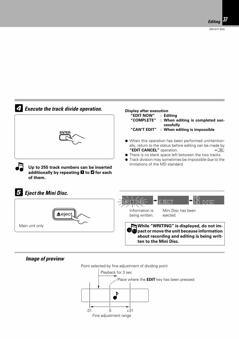
4 Execute the track divide operation.
Up to 255 track numbers can be inserted
additionally by repeating 1 to 4 for each
of them.
Image of preview
Place where the EDIT key has been pressed
Fine adjustment range
Display after execution
“EDIT NOW” : Editing
“COMPLETE” : When editing is completed suc-
cessfully
“CAN'T EDIT” : When editing is impossibleENTER
Main unit only
Playback for 3 sec
eject
Point selected by fine adjustment of dividing point
-31 0 +31
WRITING EJECT NO DISCMD
38 Editing
DM-VH7 (EN)
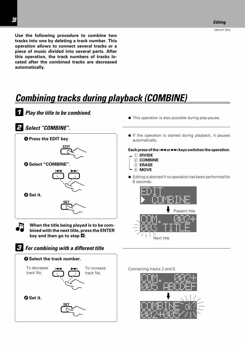
1 Play the title to be combined.
Use the following procedure to combine two
tracks into one by deleting a track number. This
operation allows to connect several tracks or a
piece of music divided into several parts. After
this operation, the track numbers of tracks lo-
cated after the combined tracks are decreased
automatically.
3 For combining with a different title
1Select the track number.
2Set it.
Combining tracks during playback (COMBINE)
When the title being played is to be com-
bined with the next title, press the ENTER
key and then go to step 4.
2Select “COMBINE”.
3Set it.
To decreasetrack No.
To increasetrack No.
Connecting tracks 2 and 5.
¶ Editing is aborted if no operation has been performed for8 seconds.
1 DIVIDE
2 COMBINE
3 ERASE
4 MOVE
2 Select “COMBINE”.
1Press the EDIT key¶ If the operation is started during playback, it pauses
automatically.
Each press of the 4 or ¢ keys switches the operation.
Present title
Next title
EDIT
4 ¢
SET
4 ¢
SET
¶ This operation is also possible during play-pause.
COMBINEEDIT
003 TITLECOM. 002+
005 ABCDEFCOM. 002+
002+005COMBINE ok?
39Editing
DM-VH7 (EN)
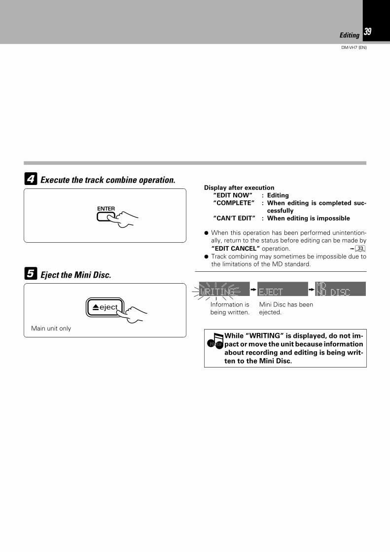
Execute the track combine operation.
¶ When this operation has been performed unintention-ally, return to the status before editing can be made by“EDIT CANCEL” operation. ‹
¶ Track combining may sometimes be impossible due tothe limitations of the MD standard.
4
Eject the Mini Disc.
While “WRITING” is displayed, do not im-
pact or move the unit because information
about recording and editing is being writ-
ten to the Mini Disc.
Information isbeing written.
Mini Disc has beenejected.
5
NoteNote
Display after execution
“EDIT NOW” : Editing
“COMPLETE” : When editing is completed suc-
cessfully
“CAN'T EDIT” : When editing is impossible
ENTER
Main unit only
eject
WRITING EJECT NO DISCMD
40 Editing
DM-VH7 (EN)
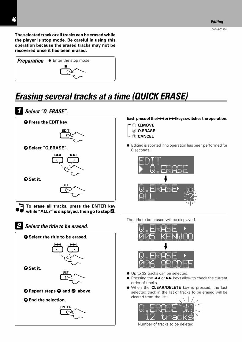
The selected track or all tracks can be erased while
the player is stop mode. Be careful in using this
operation because the erased tracks may not be
recovered once it has been erased.
Select “Q. ERASE”.1
Select the title to be erased.2
Each press of the 4 or ¢ keys switches the operation.
1 Q.MOVE
2 Q.ERASE
3 CANCEL
¶ Editing is aborted if no operation has been performed for8 seconds.
Preparation
1Press the EDIT key.
2Select “Q.ERASE”.
Erasing several tracks at a time (QUICK ERASE)
¶ Enter the stop mode.
To erase all tracks, press the ENTER key
while “ALL?” is displayed, then go to step 3.
3Set it.
1Select the title to be erased.
2Set it.
3Repeat steps 1 and 2 above.
4End the selection.
The title to be erased will be displayed.
¶ Up to 32 tracks can be selected.¶ Pressing the 1 or ¡ keys allow to check the current
order of tracks.¶ When the CLEAR/DELETE key is pressed, the last
selected track in the list of tracks to be erased will becleared from the list.
7
EDIT
4 ¢
SET
4 ¢
SET
ENTER
Number of tracks to be deleted
Q.ERASEEDIT
ALL ?Q.ERASE
005 KENWOOQ.ERASE
006 ABCDEFQ.ERASE
12 tracksQ.ERASE ok?
41Editing
DM-VH7 (EN)
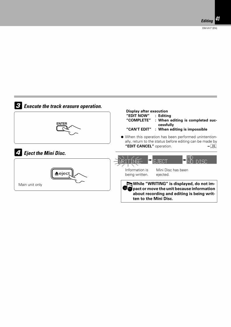
Execute the track erasure operation.3
¶ When this operation has been performed unintention-ally, return to the status before editing can be made by“EDIT CANCEL” operation. ‹
Eject the Mini Disc.
While “WRITING” is displayed, do not im-
pact or move the unit because information
about recording and editing is being writ-
ten to the Mini Disc.
Information isbeing written.
Mini Disc has beenejected.
4
NoteNote
Display after execution
“EDIT NOW” : Editing
“COMPLETE” : When editing is completed suc-
cessfully
“CAN'T EDIT” : When editing is impossible
ENTER
Main unit only
eject
WRITING EJECT NO DISCMD
42 Editing
DM-VH7 (EN)
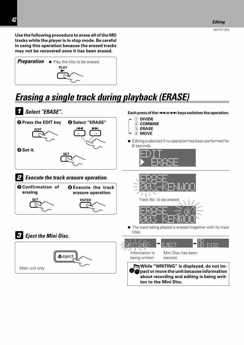
Use the following procedure to erase all of the MD
tracks while the player is in stop mode. Be careful
in using this operation because the erased tracks
may not be recovered once it has been erased.
Preparation ¶ Play the title to be erased.
Select “ERASE”.1
Execute the track erasure operation.2
1Press the EDIT key
3Set it.
Erasing a single track during playback (ERASE)
Eject the Mini Disc.
While “WRITING” is displayed, do not im-
pact or move the unit because information
about recording and editing is being writ-
ten to the Mini Disc.
Information isbeing written.
Mini Disc has beenejected.
3
NoteNote
2Select “ERASE”
Each press of the 4 or ¢ keys switches the operation.
1 DIVIDE
2 COMBINE
3 ERASE
4 MOVE
¶ Editing is aborted if no operation has been performed for8 seconds.
¶ The track being played is erased (together with its tracktitle).
Track No. to be erased
1Confirmation of
erasing2Execute the track
erasure operation.
PLAY£
EDIT 4 ¢
SET
SET ENTER
Main unit only
eject
ERASEEDIT
003 KENWOOERASE
003 KENWOOERASE ok?
WRITING EJECT NO DISCMD
43Editing
DM-VH7 (EN)
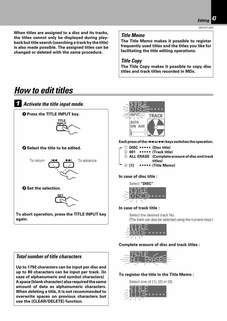
1 Activate the title input mode.
When titles are assigned to a disc and its tracks,
the titles cannot only be displayed during play-
back but title search (searching a track by the title)
is also made possible. The assigned titles can be
changed or deleted with the same procedure.
1Press the TITLE INPUT key.
To abort operation, press the TITLE INPUT key
again.
3Set the selection.
2Select the title to be edited.
Select “DISC”.
Total number of title characters
Up to 1792 characters can be input per disc and
up to 80 characters can be input per track. (In
case of alphanumeric and symbol characters)
A space (blank character) also required the same
amount of data as alphanumeric characters.
When deleting a title, it is not recommended to
overwrite spaces on previous characters but
use the (CLEAR/DELETE) function.
To advanceTo return
In case of disc title :
In case of track title :
Select the desired track No.(The track can also be selected using the numeric keys.)
How to edit titles
Each press of the 4 or ¢ keys switches the operation.
1 DISC • • • • • (Disc title)
2 001 • • • • • (Track title)
3 ALL ERASE (Complete erasure of disc and track
titles)
4 [1] • • • • • (Title Memo)
To register the title in the Title Memo :
Complete erasure of disc and track titles :
Select one of [1], [2] or [3].
TITLEINPUT
4 ¢
SET
Title MemoThe Title Memo makes it possible to register
frequently used titles and the titles you like for
facilitating the title editing operations.
Title CopyThe Title Copy makes it possible to copy disc
titles and track titles recorded in MDs.
TITLE
INPUT
AUTODINOAUXLR
TRACKDISC ÷÷÷÷÷
TITLEDISC ÷÷÷÷÷
TITLE001 ÷÷÷÷÷÷
TITLEALL ERASE
TITLE[1] ÷÷÷÷÷÷
44 Editing
DM-VH7 (EN)
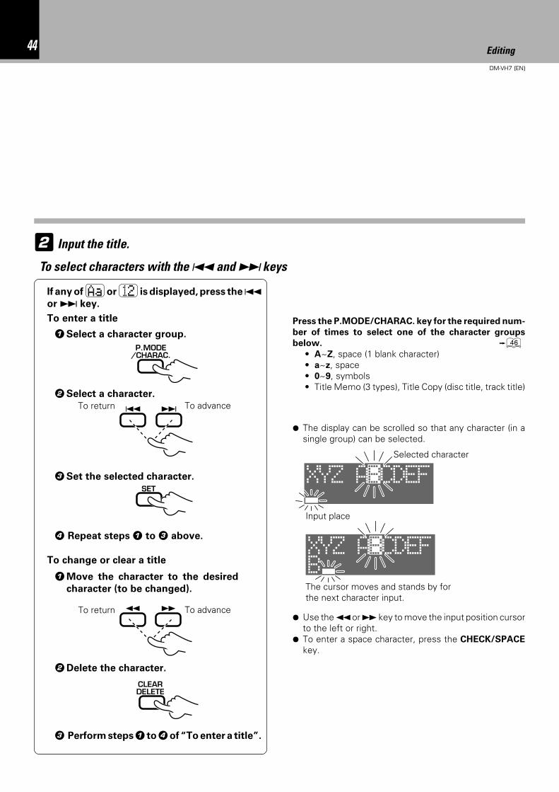
2 Input the title.
1Select a character group.
2Select a character.
4 Repeat steps 1 to 3 above.
3Set the selected character.
P.MODE/CHARAC.
Input place
Selected character
¶ The display can be scrolled so that any character (in asingle group) can be selected.
The cursor moves and stands by forthe next character input.
To advanceTo return 4 ¢
Press the P.MODE/CHARAC. key for the required num-
ber of times to select one of the character groups
below. y• A~Z, space (1 blank character)• a~z, space• 0~9, symbols• Title Memo (3 types), Title Copy (disc title, track title)
¶ Use the 1 or ¡ key to move the input position cursorto the left or right.
¶ To enter a space character, press the CHECK/SPACE
key.
SET
To select characters with the 4 and ¢ keys
If any of Aa or 12 is displayed, press the 4or ¢ key.
1Move the character to the desired
character (to be changed).
2Delete the character.
CLEARDELETE
¡ 1
To change or clear a title
To advanceTo return
To enter a title
3 Perform steps 1 to 4 of “To enter a title”.
XYZ ABCDEF
BXYZ ABCDEF
45Editing
DM-VH7 (EN)
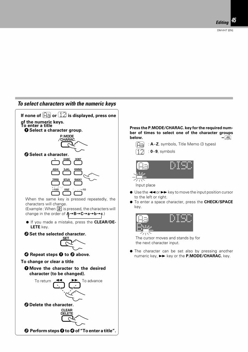
1Select a character group.
2Select a character.
3Set the selected character.
P.MODE/CHARAC.
Input place
The cursor moves and stands by forthe next character input.
Press the P.MODE/CHARAC. key for the required num-
ber of times to select one of the character groups
below. y
Aa : A~Z, symbols, Title Memo (3 types)
12 : 0~9, symbols
¶ Use the 1 or ¡ key to move the input position cursorto the left or right.
¶ To enter a space character, press the CHECK/SPACE
key.
To select characters with the numeric keys
If none of Aa or 12 is displayed, press one
of the numeric keys.
When the same key is pressed repeatedly, thecharacters will change.(Example : When 2 is pressed, the characters willchange in the order of A=B=C=a=b=c.)
2ABC1 3DEF
5JKL 6MNO4GHI
8TUV 9WXY7PRS
0QZ ,, : ? +10
& ( ) - /+100
¶ The character can be set also by pressing anothernumeric key, ¡ key or the P.MODE/CHARAC. key.
To enter a title
¶ If you made a mistake, press the CLEAR/DE-
LETE key.
SET
1Move the character to the desired
character (to be changed).
2Delete the character.
CLEARDELETE
¡ 1
To change or clear a title
To advanceTo return
3 Perform steps 1 to 4 of “To enter a title”.
4 Repeat steps 1 to 3 above.
±
Aa DISC
Aa DISCB
46 Editing
DM-VH7 (EN)
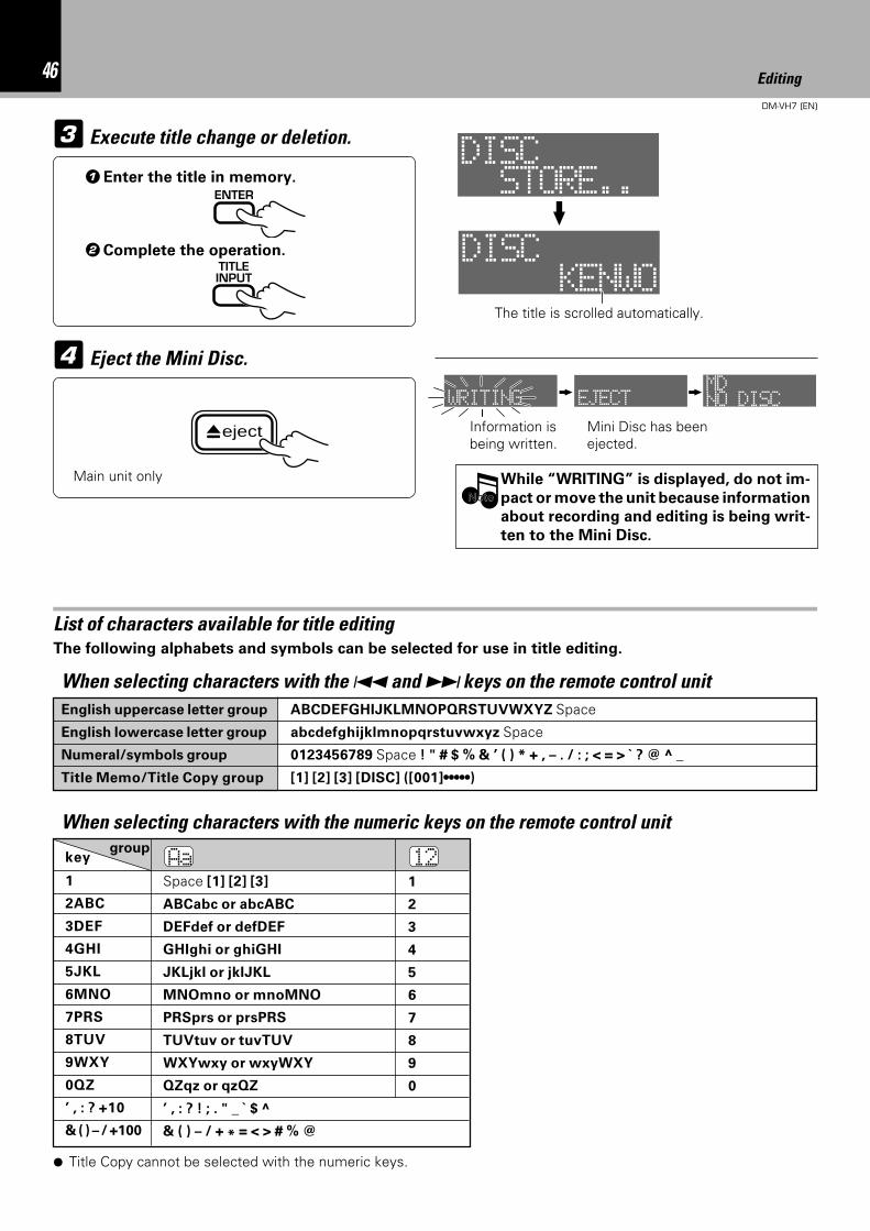
3 Execute title change or deletion.
1Enter the title in memory.ENTER
2Complete the operation.TITLEINPUT
The title is scrolled automatically.
4 Eject the Mini Disc.
English uppercase letter group ABCDEFGHIJKLMNOPQRSTUVWXYZ Space
English lowercase letter group abcdefghijklmnopqrstuvwxyz Space
Numeral/symbols group 0123456789 Space ! " # $ % & , ( ) * + , – . / : ; < = > ? @ _
Title Memo/Title Copy group [1] [2] [3] [DISC] ([001]•••••)
List of characters available for title editing
1
2ABC
3DEF
4GHI
5JKL
6MNO
7PRS
8TUV
9WXY
0QZ, , : ? +10
& ( ) – / +100
AaSpace [1] [2] [3]
ABCabc or abcABC
DEFdef or defDEF
GHIghi or ghiGHI
JKLjkl or jklJKL
MNOmno or mnoMNO
PRSprs or prsPRS
TUVtuv or tuvTUV
WXYwxy or wxyWXY
QZqz or qzQZ, , : ? ! ; . " _ $
& ( ) – / + * = < > # % @
121
2
3
4
5
6
7
8
9
0
When selecting characters with the numeric keys on the remote control unit
The following alphabets and symbols can be selected for use in title editing.
Main unit only
Information isbeing written.
Mini Disc has beenejected.
While “WRITING” is displayed, do not im-
pact or move the unit because information
about recording and editing is being writ-
ten to the Mini Disc.
NoteNote
When selecting characters with the 4 and ¢ keys on the remote control unit
keygroup
¶ Title Copy cannot be selected with the numeric keys.
eject
TOTAL
DISC
STORE..
DISC
KENWO
WRITING EJECT NO DISCMD
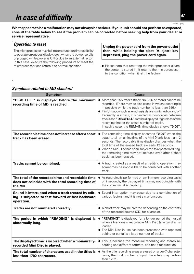
47In case of difficulty
DM-VH7 (EN)
In case of difficultyWhat appears to be a malfunction may not always be serious. If your unit should not perform as expected,
consult the table below to see if the problem can be corrected before seeking help from your dealer or
service representative.
Operation to resetThe microprocessor may fall into malfunction (impossibilityto operate erroneous display, etc.) when the power cord isunplugged while power is ON or due to an external factor.In this case, execute the following procedure to reset themicroprocessor and return it to normal condition.
Unplug the power cord from the power outlet
then, while holding the eject (0 eject) key
depressed, plug the power cord again.
Symptoms related to MD standardSymptom
¶ More than 255 tracks (track No. 256 or more) cannot berecorded. (There may be also cases in which recording isimpossible while the track number is less than 256.)
¶ If information such as emphasis data is switched on and offfrequently in a track, it is handled as boundaries betweentracks and “DISC FULL” may be displayed regardless of therecording time or the actual number of tracks.In such a case, the REMAIN time display shows “0:00”.
Cause
“DISC FULL” is displayed before the maximum
recording time of MD is reached.
¶ Please note that resetting the microprocessor clearsthe contents stored in, it returns the microprocessorto the condition when it left the factory.
¶ The remaining time display becomes “0:00” when theactual total remaining time of the Mini Disc is less than 12seconds. The recordable time display changes when thetotal time of the erased track exceeds 12 seconds.
¶ When a Mini Disc has been subjected to repeated editing,the remaining time may not increase even after a shorttrack has been erased.
The recordable time does not increase after a short
track has been erased.
Tracks cannot be combined. ¶ A track created as a result of an editing operation maysometimes be impossible to be combined with anothertrack.
The total of the recorded time and recordable time
does not coincide with the total recording time of
the MD.
¶ As recording is performed on a minimum recording basisof 2 seconds, the displayed time may not coincide withthe consumed disc capacity.
Sound is interrupted when a track created by edit-
ing is subjected to fast forward or fast backward
operation.
¶ Sound interruption may occur due to a combination ofvarious factors, and it is not a malfunction.
Tracks are not numbered correctly. ¶ A short track may be created depending on the contentsof the recorded source (CD, for example).
The period in which “READING” is displayed is
abnormally long.
¶ “READING” is displayed for a longer period than usualwhen a brand-new recordable Mini Disc (a virgin disc) isloaded.
¶ The Mini Disc in use has been processed with repeatedediting or contains a large number of tracks.
The displayed time is incorrect when a monaurally-
recorded Mini Disc is played.
¶ This is because the monaural recording and stereo re-cording use different formats, and not a malfunction.
The total number of characters used in the titles is
less than 1792 characters.
¶ As the title recording areas are used on a per-7-characterbasis, the total number of input characters may be lessthan 1792.
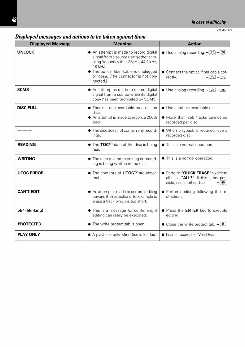
48 In case of difficulty
DM-VH7 (EN)
ActionMeaningDisplayed Message
¶ An attempt is made to record digitalsignal from a source using other sam-pling frequency than 38kHz, 44.1 kHz,48 kHz.
¶ The optical fiber cable is unpluggedor loose. (The connector is not con-nected.)
¶ Use analog recording.∞§
¶ Connect the optical fiber cable cor-rectly. @#
UNLOCK
Displayed messages and actions to be taken against them
SCMS ¶ An attempt is made to record digitalsignal from a source while its digitalcopy has been prohibited by SCMS.
¶ Use analog recording.∞§
¶ There is no recordable area on thedisc.
¶ An attempt is made to record a 256thtrack.
¶ Use another recordable disc.
¶ More than 255 tracks cannot berecorded per disc.
DISC FULL
¶ The disc does not contain any record-ings.
¶ When playback is required, use arecorded disc.
–– –– ––
¶ This is a normal operation.¶ The TOC*1 data of the disc is beingread.
READING
¶ This is a normal operation.¶ The data related to editing or record-ing is being written in the disc.
WRITING
¶ Perform “QUICK ERASE” to deleteall titles “ALL?”. If this is not pos-sible, use another disc. ‚
¶ The contents of UTOC*2 are abnor-mal.
UTOC ERROR
¶ Perform editing following the re-strictions.
¶ An attempt is made to perform editingbeyond the restrictions, for example toerase a track which is too short.
CAN'T EDIT
¶ Press the ENTER key to executeediting.
¶ This is a message for confirming ifediting can really be executed.
ok? (blinking)
¶ Close the write protect tab. 8¶ The write protect tab is open.
¶ Load a recordable Mini Disc.¶ A playback-only Mini Disc is loaded.
PROTECTED
PLAY ONLY
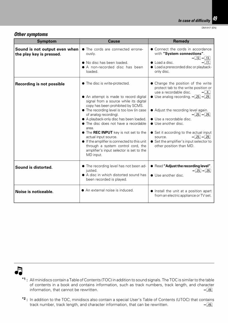
49In case of difficulty
DM-VH7 (EN)
Other symptomsRemedyCauseSymptom
¶ The cords are connected errone-ously.
¶ No disc has been loaded.¶ A non-recorded disc has been
loaded.
Sound is not output even when
the play key is pressed.
¶ Connect the cords in accordancewith “System connections”.
@#¶ Load a disc. &¶ Load a prerecorded disc or playback-
only disc.
Recording is not possible ¶ The disc is write-protected.
¶ An attempt is made to record digitalsignal from a source while its digitalcopy has been prohibited by SCMS.
¶ The recording level is too low (in caseof analog recording).
¶ A playback-only disc has been loaded.¶ The disc does not have a recordable
area.¶ The REC INPUT key is not set to the
actual input source.¶ If the amplifier is connected to this unit
through a system control cord, theamplifier’s input selector is set to theMD input.
¶ Change the position of the writeprotect tab to the write position oruse a recordable disc. 8
¶ Use analog recording.∞§
¶ Adjust the recording level again.∞§
¶ Use a recordable disc.¶ Use another disc.
¶ Set it according to the actual inputsource. ∞§
¶ Set the amplifier’s input selector toother position than MD.
Sound is distorted. ¶ The recording level has not been ad-justed.
¶ A disc in which distorted sound hasbeen recorded is played.
¶ Read “Adjust the recording level”.∞§
¶ Use another disc.
¶ An external noise is induced. ¶ Install the unit at a position apartfrom an electric appliance or TV set.
Noise is noticeable.
*1 : All minidiscs contain a Table of Contents (TOC) in addition to sound signals. The TOC is similar to the tableof contents in a book and contains information, such as track numbers, track length, and characterinformation, that cannot be rewritten. i
*2 : In addition to the TOC, minidiscs also contain a special User’s Table of Contents (UTOC) that containstrack number, track length, and character information, that can be rewritten. i
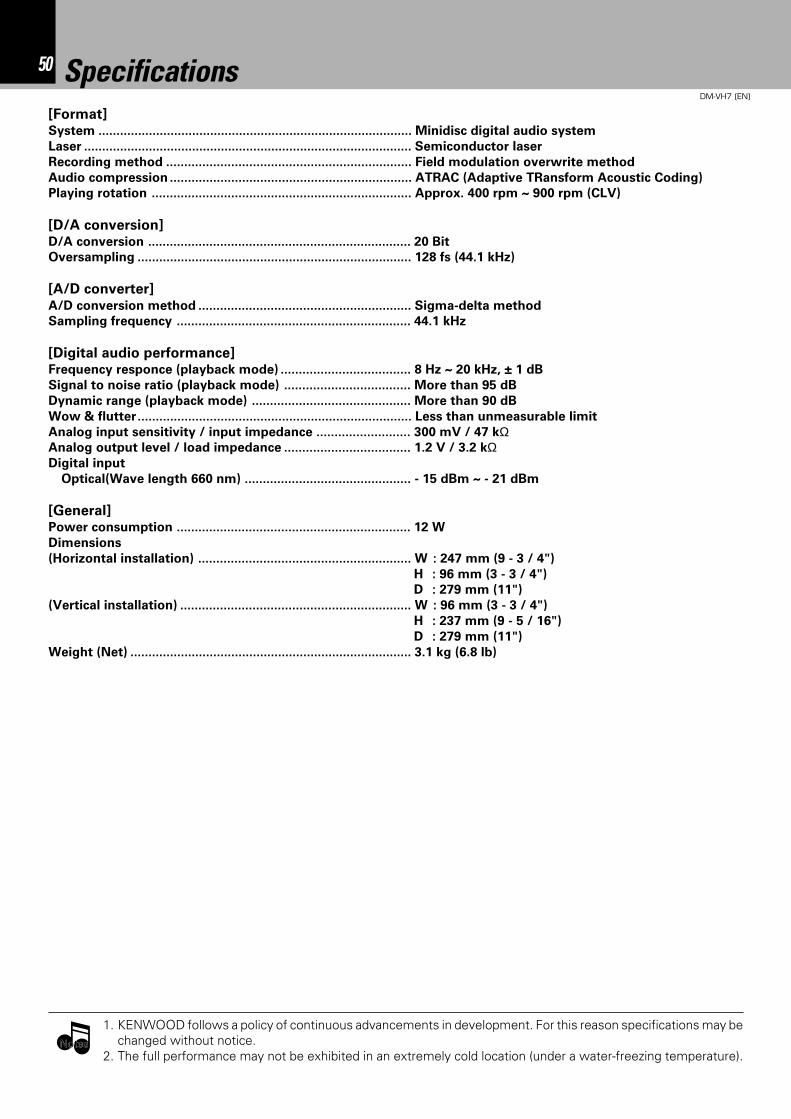
50 In case of difficulty
DM-VH7 (EN)
Specifications[Format]System ....................................................................................... Minidisc digital audio system
Laser ........................................................................................... Semiconductor laser
Recording method .................................................................... Field modulation overwrite method
Audio compression ................................................................... ATRAC (Adaptive TRansform Acoustic Coding)
Playing rotation ........................................................................ Approx. 400 rpm ~ 900 rpm (CLV)
[D/A conversion]D/A conversion ......................................................................... 20 Bit
Oversampling ............................................................................ 128 fs (44.1 kHz)
[A/D converter]
A/D conversion method ........................................................... Sigma-delta method
Sampling frequency ................................................................. 44.1 kHz
[Digital audio performance]Frequency responce (playback mode) .................................... 8 Hz ~ 20 kHz, ± 1 dB
Signal to noise ratio (playback mode) ................................... More than 95 dB
Dynamic range (playback mode) ............................................ More than 90 dB
Wow & flutter............................................................................ Less than unmeasurable limit
Analog input sensitivity / input impedance .......................... 300 mV / 47 kΩAnalog output level / load impedance ................................... 1.2 V / 3.2 kΩDigital input
Optical(Wave length 660 nm) .............................................. - 15 dBm ~ - 21 dBm
[General]Power consumption ................................................................. 12 W
Dimensions
(Horizontal installation) ........................................................... W : 247 mm (9 - 3 / 4")
H : 96 mm (3 - 3 / 4")
D : 279 mm (11")
(Vertical installation) ................................................................ W : 96 mm (3 - 3 / 4")
H : 237 mm (9 - 5 / 16")
D : 279 mm (11")
Weight (Net) .............................................................................. 3.1 kg (6.8 lb)
1. KENWOOD follows a policy of continuous advancements in development. For this reason specifications may bechanged without notice.
2. The full performance may not be exhibited in an extremely cold location (under a water-freezing temperature).NotesNotes

51In case of difficulty
DM-VH7 (EN)

For your recordsRecord the serial number, found on the back of theunit, in the spaces designated on the warranty card,and in the space provided below. Refer to the modeland serial numbers whenever you call upon yourdealer for information or service on this product.
Model Serial Number


![No Model VIN 1 (DM) SANTAFE [DM] KMHSU81BSCU000212 2 … Engine YF and D… · 37 (dm) santafe [dm] kmhst81bsdu023920 38 (dm) santafe [dm] kmhst81bsdu023926 39 (dm) santafe [dm] kmhst81bsdu023930](https://img.pdfslide.us/doc/110x75/6017564e29e54a6dde7ebe6b/no-model-vin-1-dm-santafe-dm-kmhsu81bscu000212-2-engine-yf-and-d-37-dm-santafe.jpg)