Embed Size (px)
Citation preview
1
TM 55-1945-205-24-3-1TECHNICAL MANUAL
UNIT, DIRECT SUPPORT AND GENERAL SUPPORT MAINTENANCE MANUAL
FOR
MODULAR CAUSEWAY SYSTEM (MCS)WARPING TUG (WT)
WT-1NSN 1945-01-473-2285
This manual supersedes TM 55-1945-205-24-1 dated 29 August 1997, including all changes.
DISTRIBUTION STATEMENT A - Approved for public release; distribution is unlimited.
HEADQUARTERS, DEPARTMENT OF THE ARMY 30 AUGUST 2003
FLOATING CAUSEWAY
WARPING TUG CAUSEWAY FERRY
ROLL-ON/ROLL-OFFDISCHARGE FACILITY
LCU-2000
LSV
TM 55-1945-205-24-3-1
HEADQUARTERSDEPARTMENT OF THE ARMY
WASHINGTON, D.C. 30 AUGUST 2003
TECHNICAL MANUAL
UNIT, DIRECT SUPPORT AND GENERAL SUPPORT MAINTENANCE MANUALFOR
MODULAR CAUSEWAY SYSTEM (MCS) WARPING TUG (WT)
WT-1NSN 1945-01-473-2285
This manual supersedes TM 55-1945-205-24-1 dated 29 August 1997, including all changes.
TABLE OF CONTENTS WP Sequence No.
WARNING SUMMARY
HOW TO USE THIS MANUAL
General Information .............................................................................................................. 0001 00
CHAPTER 1 - DESCRIPTION AND THEORY OF OPERATIONDescription and Data, Equipment Characteristics, Capabilities and Features ...................... 0002 00Description and Data, Location and Description of Major Components .............................. 0003 00Description and Data, Equipment Data ................................................................................. 0004 00Theory of Operation .............................................................................................................. 0005 00
CHAPTER 2 - UNIT, DIRECT SUPPORT AND GENERAL SUPPORT TROUBLESHOOTING PROCEDURESTroubleshooting Procedures Index ........................................................................................ 0006 00Exhaust Plenum Ventilation Fan Will Not Operate .............................................................. 0007 00Vent Fan Operating Status Light Does Not Illuminate ......................................................... 0008 00
DISTRIBUTION STATEMENT A - Approved for public release; distribution is unlimited.
REPORTING ERRORS AND RECOMMENDING IMPROVEMENTS
You can help improve this publication. If you find any mistakes or if you know of a way to improve theprocedures, please let us know. Submit your DA Form 2028 (Recommended Changes to EquipmentTechnical Publications), through the Internet, on the Army Electronic Product Support (AEPS) website.The Internet address is http://aeps.ria.army.mil. If you need a password, scroll down and click on“ACCESS REQUEST FORM”. The DA Form 2028 is located in the ONLINE FORMS PROCESSINGsection of the AEPS. Fill out the form and click on SUBMIT. Using this form on the AEPS will enable us torespond quicker to your comments and better manage the DA Form 2028 program. You may also mail,fax or email your letter or DA Form 2028 direct to: AMSTA-LC-CI / TECH PUBS, TACOM-RI, 1 RockIsland Arsenal, Rock Island, IL 61299-7630. The email address is [email protected] fax number is DSN 793-0726 or Commercial (309) 782-0726.
i Change 1
TM 55-1945-205-24-3-1
TABLE OF CONTENTS (CONT’D)
WP Sequence No.
CHAPTER 2 - UNIT, DIRECT SUPPORT AND GENERAL SUPPORT TROUBLESHOOTING PROCEDURES (CONT’D)
Flood Alarm Beeper Does Not Operate ................................................................................ 0009 00Flood Alarm Light 3A2DS2 Does Not Illuminate in Alarm Mode ....................................... 0010 00Exhaust Plenum Ventilation Fan Does Not Work ................................................................. 0011 00Diesel Engine, Propulsion Module Becomes Hotter Than Normal Operating Temperature 0012 00Drive Train Does Not Operate Freely and Smoothly, Excessive Vibration Is
Experienced During Operation ............................................................................... 0013 00Diesel Engine Malfunctions .................................................................................................. 0014 00Diesel Engine Smoke Is Consistently White In Nature ......................................................... 0015 00Diesel Engine Has No Exhaust Smoke ................................................................................. 0016 00Diesel Engine Does Not Run Properly .................................................................................. 0017 00Diesel Engine Speed Control, Improper Speed Control From Operators Cab ...................... 0018 00Diesel Engine Fuel System Not Receiving Fuel From Tank ................................................ 0019 00Diesel Engine Is Misfiring Caused By Clogged or Damaged Injectors ................................ 0020 00Diesel Engine Governor, Electronic Governor Junction Box A4 Is Completely Dead,
Actuator Lever Stays At Miminum Position When Power Is Applied To Governor ............................................................................................. 0021 00
Diesel Engine Governor Is Not Operating, Electronic Governor Actuator Goes To Full Stroke When DC Power Is Applied ........................................................................ 0022 00
Diesel Engine Exhaust System Has Developed Water Leaks ............................................... 0023 00Transfer Case Cooling System, Water Is Not Expelling Out Of Exhaust Outlet Port
and/or Transfer Case Cooling System Port ............................................................. 0024 00Diesel Engine Exhaust System Has Developed Exhaust Leaks ............................................ 0025 00Diesel Engine Starting System, Does Not Start In Cold Temperatures ................................ 0026 00Diesel Engine Lubrication System, Low Engine Oil Pressure (Audible Alarm and
Warning Light On) (Normal Operation) ................................................................. 0027 00Diesel Engine Overheating (Audible Alarm and Warning Light On) ................................... 0028 00Marine Gear Malfunctions .................................................................................................... 0029 00Marine Gear, Clutch Will Not Engage In Engage/Backflush Directions .............................. 0030 00Transfer Case Malfunctions .................................................................................................. 0031 00Hydraulic System Has High Pressure .................................................................................... 0032 00Hydraulic System Has No Pressure ....................................................................................... 0033 00Pump-Jet Steering, No Steering From Operators Cab, Low Hydraulic System Pressure ..... 0034 00Pump-Jet, No Propulsion ....................................................................................................... 0035 00Pump-Jet Develops Only A Small Amount of Thrust (Not Enough Water Is
Being Delivered) ..................................................................................................... 0036 00Steering System, No Steering Control ................................................................................... 0037 00Operators Cab, No Steering Control Indication for the Pump-Jet ......................................... 0038 00Operators Cab, Steering Reacts Sluggishly ........................................................................... 0039 00Steering System, No Steering From Operators Cab .............................................................. 0040 00Diesel Engine Charging System, Alternator Is Not Charging the Batteries .......................... 0041 00Operators Cab, Ammeter Indicates Discharging of System .................................................. 0042 00Bilge Pumps Do Not Function .............................................................................................. 0043 00Bilge Pumps Will Not Function In Test Mode (From Bilge Junction Boxes A5 and A7) .... 0044 00Bilge Pumps Will Not Function In Remote Mode From the Operators Cab ........................ 0045 00Bilge Pump Output Has Reduced Flow ................................................................................. 0046 00Bilge Pump Will Not Shut Off .............................................................................................. 0047 00
Change 1 ii
TM 55-1945-205-24-3-1
TABLE OF CONTENTS (CONT’D)
WP Sequence No.
CHAPTER 2 - UNIT, DIRECT SUPPORT AND GENERAL SUPPORT TROUBLESHOOTING PROCEDURES (CONT’D)
Bilge Pump Status Lights Are Not Functional ...................................................................... 0048 00Bilge Pump, Water Entering Bilge Pump Discharge Line When Pump Is Not Operating ... 0049 00Fire Suppression System, Thermal Detector Does Not Trip Fire Alarm .............................. 0050 00Fire Alarm Horn 3A4LS2 Does Not Operate ........................................................................ 0051 00Fire Alarm Light 3A2DS3 (Stbd) or 3A2DS1 (Port) Does Not Illuminate In Alarm Mode . 0052 00Interconnect Cable Not Working Between Modules ............................................................. 0053 00Operators Cab Control Panels, No Power ............................................................................. 0054 00Marine Gear Clutch Status Light, Not Operational ............................................................... 0055 00Operators Cab Gauge Lights Will Not Operate or Vary in Brightness ................................. 0056 00Operators Cab Accessories Do Not Function, Troubleshooting Procedures ........................ 0057 00Operators Cab Circuit Breaker Panel, Circuits Controlled By 3A3CB1-3A3CB10 Are
Not Functioning ...................................................................................................... 0058 00Operators Cab Circuit Breaker Panel, A Circuit Controlled By 3A3CB1-3A3CB10 Is
Not Functioning ...................................................................................................... 0059 00Operators Cab Circuit Breaker Panel, No Voltage at Test Jacks When Using Built In
Test Switch 3A3S1 In Any Position ....................................................................... 0060 00Operators Cab Circuit Breaker Panel, No Voltage at Test Jacks When Using Built In
Test Switch 3A3S1 .................................................................................................. 0061 00Spotlight Not Functioning, Troubleshooting Procedures ...................................................... 0062 00Operators Cab Fan Control Does Not Work On Low (DELETED) ..................................... 0063 00Operators Cab Heater Does Not Operate .............................................................................. 0063 10Operators Cab, Only Fan B1B Operates Wiith Heater Fan Control In High (DELETED) .. 0064 00Operators Cab, Heater Fan B1B Does Not Operate With Fan
Control in High (DELETED) .................................................................................. 0065 00Operators Cab, Defroster Fan Does Not Operate .................................................................. 0066 00Public Address Set (Loudhailer) Has No Power ................................................................... 0067 00Public Address Set (Loudhailer) Will Not Transmit Voice To Hailer Horn (Loudhailer
External Speaker) .................................................................................................... 0068 00Public Address Set (Loudhailer) Will Not Transmit Fog Signal To Hailer Horn
(Loudhailer External Speaker) ................................................................................ 0069 00Public Address Set (Loudhailer) Will Not Transmit VHF/FM DSC Transceiver Audio to
Hailer Horn (Loudhailer External Speaker) ............................................................ 0070 00VHF/FM DSC Transceiver Has No Power ........................................................................... 0071 00VHF/FM DSC Transceiver Will Not Receive ....................................................................... 0072 00VHF/FM DSC Transceiver Will Not Transmit ..................................................................... 0073 00VHF/FM DSC Transceiver Does Not Display A Valid Position .......................................... 0074 00Precision Lightweight Global Positioning Receiver (PLGR) Has No Power ....................... 0075 00Precision Lightweight Global Positioning Receiver (PLGR) Does Not Display
A Valid Position ...................................................................................................... 0076 00Navigation Lights, Audible Pulse Beeper Sounds ................................................................ 0077 00Mast Assembly Lamp Fixture On Main or Stub Mast Not Working .................................... 0078 00Main Mast, Loss of Power ..................................................................................................... 0079 00Mast Enclosure Lamp Indicator Light On Junction Box Not Working ................................ 0080 00Navigation Lights Will Not Function .................................................................................... 0081 00Navigation Lights, One or More Are Not Functioning ......................................................... 0082 00Stub Mast Stern Light Not Functioning ................................................................................ 0083 00
iii Change 1
TM 55-1945-205-24-3-1
TABLE OF CONTENTS (CONT’D)
WP Sequence No.
CHAPTER 2 - UNIT, DIRECT SUPPORT AND GENERAL SUPPORT TROUBLESHOOTING PROCEDURES (CONT’D)
Alternator, Operation Checkout and Troubleshooting Procedure ......................................... 0083 10Voltage Regulator, Operation Checkout and Troubleshooting Procedure ............................ 0083 20Main Mast Deck Floodlight(s) Will Not Function ................................................................ 0083 30
CHAPTER 3 - UNIT, DIRECT SUPPORT AND GENERAL SUPPORT MAINTENANCE INSTRUCTIONSService Upon Receipt of Materiel ......................................................................................... 0084 00Preventive Maintenance Checks and Services (PMCS) Procedures, Introduction ............... 0085 00Preventive Maintenance Checks and Services (PMCS) and Lubrication Procedures ........... 0086 00Propulsion Module, Vent ....................................................................................................... 0086 10Powered Section Intake Plenum Assembly, Removal and Installation ................................. 0087 00Powered Section Intake Plenum Air Intake Louver, Replacement ....................................... 0088 00Powered Section Intake Plenum Wire Rope, Replacement ................................................... 0089 00Powered Section Intake Plenum Interconnect Cover, Removal and Installation .................. 0090 00Powered Section Intake Plenum Interconnect Cover Gasket, Replacement ......................... 0091 00Powered Section Intake Plenum Flocs Remote Access Cover, Removal and Installation ... 0091 10Powered Section Intake Plenum Flocs Remote Access Cover Gasket, Replacement ........... 0091 20Powered Section Exhaust Plenum, Removal and Installation ............................................... 0092 00Powered Section Exhaust Plenum Cover, Replacement ....................................................... 0093 00Powered Section Exhaust Plenum Door, Replacement ......................................................... 0094 00Powered Section Exhaust Plenum Locking Handle, Removal and Installation .................... 0095 00Powered Section Exhaust Plenum Vent Fan, Replacement .................................................. 0096 00Powered Section Operators Cab Side Access Panel, Removal and Installation ................... 0097 00Powered Section Operators Cab, Removal and Installation .................................................. 0098 00Jumper Cables, Installation and Removal ............................................................................. 0098 10Powered Section Engine Hatch, Removal and Installation ................................................... 0099 00Powered Section Thruster Hatch, Removal and Installation ................................................. 0100 00Raw Water Cooling System Butterfly (Sea Chest) Valve, Replacement .............................. 0101 00Raw Water Cooling System Sea Chest Zinc Anodes, Replacement ..................................... 0102 00Raw Water Cooling System Strainer Basket, Removal, Cleaning and Installation .............. 0103 00Raw Water Cooling System Duplex Strainer, Replacement and Adjustment ....................... 0104 00Raw Water Cooling System Duplex Strainer, Repair ........................................................... 0105 00Raw Water Cooling System Butterfly (Sea Chest) Valve To Duplex Strainer
Water Hose, Replacement ....................................................................................... 0106 00Raw Water Cooling System Duplex Strainer To Raw Water Pump Hose, Replacement ..... 0107 00Raw Water Cooling System Exhaust Shutoff Ball Valve, Replacement .............................. 0108 00Raw Water Cooling System Shutoff Ball Valve To Marine Gear Heat Exchanger
Water Hose, Replacement ....................................................................................... 0109 00Raw Water Cooling System Shutoff Ball Valve To Exhaust Crossover Tee Water
Hose, Replacement .................................................................................................. 0110 00Raw Water Cooling System Shutoff Ball Valve To Transfer Case Heat Exchanger
Water Hose, Replacement ....................................................................................... 0111 00Raw Water Cooling System Transfer Case Heat Exchanger To Overboard Discharge
Water Hose, Replacement ....................................................................................... 0112 00Raw Water Cooling System Marine Gear Heat Exchanger To Engine Heat Exchanger
Water Hose, Replacement ....................................................................................... 0113 00Raw Water Cooling System Pump To Engine Fuel Cooler Water Hose, Replacement ....... 0114 00Drive Train Transfer Case To Pump-Jet Machinery Guards, Removal and Installation ...... 0115 00
Change 1 iv
TM 55-1945-205-24-3-1
TABLE OF CONTENTS (CONT’D)
WP Sequence No.
CHAPTER 3 - UNIT, DIRECT SUPPORT AND GENERAL SUPPORT MAINTENANCE INSTRUCTIONS (CONT’D)
Drive Train Marine Gear To Transfer Case Machinery Guards, Removal and Installation . 0116 00Drive Train Drive Shafts, Inspection and Servicing ............................................................. 0117 00Drive Train Drive Shafts, Removal and Installation ............................................................. 0118 00Drive Train, Alignment ......................................................................................................... 0119 00Drive Train Main Engine Oil Filter, Replacement ................................................................ 0120 00Drive Train Fast Lube System Hoses, Replacement ............................................................. 0121 00Drive Train Engine Oil Filter Inlet Hose, Replacement ........................................................ 0122 00Drive Train Engine Oil Filter Outlet Hose, Replacement ..................................................... 0123 00Drive Train Engine Oil Filter Adaptor, Replacement ........................................................... 0124 00Drive Train Engine Heater Hose, Replacement (DELETED)................................................ 0125 00Drive Train Heater Hose Female Quick Disconnect, Replacement (DELETED) ................. 0126 00Pump-Jet Braking Valve, Replacement ................................................................................. 0127 00Pump-Jet Gearcase, Servicing ............................................................................................... 0128 00Pump-Jet Primary Planetary Gearbox, Servicing .................................................................. 0129 00Pump-Jet Primary Planetary Gearing, Replacement ............................................................. 0130 00Pump-Jet Auxiliary Planetary Gearbox, Servicing ............................................................... 0131 00Pump-Jet Auxiliary Planetary Gearing, Replacement ........................................................... 0132 00Pump-Jet Hydro-Motor, Removal and Installation ............................................................... 0133 00Pump-Jet Expansion Tank, Cleaning .................................................................................... 0134 00Pump-Jet Expansion Tank, Replacement .............................................................................. 0135 00Hydraulic System, Vent Air .................................................................................................. 0136 00Hydraulic System, Vent Pressure .......................................................................................... 0136 10Hydraulic System, Adjustment .............................................................................................. 0137 00Hydraulic System Flow, Adjustment .................................................................................... 0138 00Hydraulic Steering System, Adjustment ............................................................................... 0139 00Hydraulic System Reservoir Fluid Level Subassembly, Removal, Testing and Installation 0140 00Hydraulic System Reservoir Tank Strainer, Removal, Cleaning and Installation ................ 0141 00Hydraulic System Reservoir, Draining and Cleaning ........................................................... 0142 00Hydraulic System Reservoir, Servicing ................................................................................ 0143 00Hydraulic System Filter Elements, Replacement .................................................................. 0144 00Hydraulic System Reservoir, Replacement ........................................................................... 0145 00Hydraulic System Return Filter, Replacement ...................................................................... 0146 00Hydraulic System Reservoir Breather/Filler, Replacement .................................................. 0147 00Hydraulic System Reservoir Sight Gauge, Replacement ...................................................... 0148 00Hydraulic System Reservoir To Hydraulic Pump Suction Hose, Replacement .................... 0149 00Hydraulic System Pump To Pressure Filter Tube, Replacement .......................................... 0150 00Hydraulic System Way-Valve Port M To Pump-Jet Manifold Port H Hydraulic
Line, Replacement .................................................................................................. 0151 00Hydraulic System Way-Valve Port N To Pump-Jet Manifold Port J Hydraulic
Line, Replacement .................................................................................................. 0152 00Hydraulic System Pump-Jet Manifold To 3/2 Ball Valve Line, Replacement ..................... 0153 00Hydraulic System 3/2 Ball Valve To Hand Pump Hydraulic Line, Replacement ................ 0154 00Hydraulic System 3/2 Ball Valve Line To Pump-Jet Brake, Replacement ........................... 0155 00Hydraulic System Pump-Jet Hydraulic Motor To Reservoir Return Line, Replacement ..... 0156 00Hydraulic System Way-Valve To Reservoir Return Line, Replacement .............................. 0157 00Hydraulic System Pump To Reservoir Return Line, Replacement ....................................... 0158 00Hydraulic System Way-Valve To Hydraulic Pump Line, Replacement ............................... 0159 00
v Change 1
TM 55-1945-205-24-3-1
TABLE OF CONTENTS (CONT’D)
WP Sequence No.
CHAPTER 3 - UNIT, DIRECT SUPPORT AND GENERAL SUPPORT MAINTENANCE INSTRUCTIONS (CONT’D)
Hydraulic System Pressure Filter to Way-Valve Line, Replacement ................................... 0160 00Hydraulic System Needle Valve To Jet-Pump Motor Hydraulic Line, Replacement ........... 0161 00Hydraulic System Reservoir To Return Line Filter Hose, Replacement .............................. 0162 00Hydraulic Pump, Replacement .............................................................................................. 0163 00Hydraulic Pump, Repair ........................................................................................................ 0164 00Hydraulic Hand Pump, Servicing .......................................................................................... 0165 00Hydraulic Hand Pump, Replacement .................................................................................... 0166 00Hydraulic Hand Pump, Bleeding ........................................................................................... 0167 00Hydraulic Way-Valve, Replacement ..................................................................................... 0168 00Hydraulic Way-Valve, Repair .............................................................................................. 0169 00Hydraulic System 3/2 Ball Valve, Replacement ................................................................... 0170 00Pump-Jet Planetary Gearing Feedback Unit, Replacement ................................................... 0171 00Alternator Belt Guard, Removal and Installation .................................................................. 0172 00Alternator Drive Belts, Replacement .................................................................................... 0173 00Alternator, Replacement ........................................................................................................ 0174 00Alternator Drive Belts, Adjustment ....................................................................................... 0175 00Electrical System Alternator Temperature Sensor, Replacement ......................................... 0175 10Engine Exhaust System, Removal, Inspection and Installation ............................................ 0176 00Engine Exhaust Muffler, Replacement .................................................................................. 0177 00Bilge Pump Float Switch, Cleaning and Testing ................................................................... 0178 00Bilge Pump Check Valve, Removal, Cleaning, Inspection and Installation ......................... 0179 00Bilge Float Switch With Guard, Replacement ...................................................................... 0180 00Bilge Check Valve, Replacement .......................................................................................... 0181 00Bilge Pump, Replacement ..................................................................................................... 0182 00Fuel System Filler Neck Strainer, Removal, Cleaning and Installation ................................ 0183 00Fuel System Tank, Inspection For Water .............................................................................. 0184 00Fuel System Tank, Draining .................................................................................................. 0185 00Fuel System Access Covers, Removal and Installation ........................................................ 0186 00Fuel System Tank, Inspection, Internal ................................................................................. 0187 00Fuel System Tank, Cleaning .................................................................................................. 0188 00Fuel System Filler Neck Check Valve, Replacement ........................................................... 0189 00Fuel System Ball Valve, Replacement .................................................................................. 0190 00Fuel System Tank Sight Level, Replacement ........................................................................ 0191 00Fuel System Tank Sight Level Shutoff Cock, Replacement ................................................. 0192 00Fuel System Rubber Hoses, Replacement ............................................................................. 0193 00Fuel System Tank Rigid Fuel Line, Replacement ................................................................. 0194 00Fuel System Fuel Water Separator, Draining ........................................................................ 0195 00Fuel System Fuel Water Separator Filter Element, Replacement ......................................... 0196 00Fuel System Fuel Water Separator Assembly, Replacement ................................................ 0197 00Powered Section Main Batteries Negative Lead Terminals, Removal and Installation ........ 0198 00Electrical System Batteries, Testing and Servicing ............................................................... 0199 00Electrical System Batteries, Replacement ............................................................................. 0200 00Electrical System Battery Box, Replacement ........................................................................ 0201 00Electrical System Battery Temperature Sensor, Replacement .............................................. 0201 10Electrical System Junction Box JB1 Fuse, Replacement ...................................................... 0202 00Electrical System Module Interconnect Assembly, Removal, Inspection and Installation ... 0203 00Electrical System Module Interconnect Cable, Repair .......................................................... 0204 00
Change 1 vi
TM 55-1945-205-24-3-1
TABLE OF CONTENTS (CONT’D)
WP Sequence No.
CHAPTER 3 - UNIT, DIRECT SUPPORT AND GENERAL SUPPORT MAINTENANCE INSTRUCTIONS (CONT’D)
Electrical System Pump-Jet Junction Box A2jb2, Removal and Installation ....................... 0205 00Electrical System Pump-Jet Thruster Junction Box A2jb2, Repair ...................................... 0206 00Electrical System Propulsion Module Junction Box A3, Removal and Installation ............. 0207 00Electrical System Propulsion Module Junction Box A3, Repair .......................................... 0208 00Electrical System Engine Junction Box A4, Removal and Installation ................................ 0209 00Electrical System Engine Junction Box Assembly A4, Repair ............................................. 0210 00Electrical System Bilge Pump Control Assembly A5, Removal and Installation ................. 0211 00Electrical System Bilge Pump Control Panel Assembly A5, Repair .................................... 0212 00Electrical System Propulsion Module Circuit Breaker Panel A6, Removal and Installation 0213 00Electrical System Propulsion Module Circuit Breaker Panel A6, Repair ............................. 0214 00Electrical System Single Bilge Pump Control Assembly A7, Removal and Installation ..... 0215 00Electrical System Single Bilge Pump Control Assembly A7, Repair ................................... 0216 00Electrical System Vent Fan Relay Enclosure Assembly A8, Removal and Installation ....... 0217 00Electrical System Vent Fan Relay Enclosure Assembly A8, Repair .................................... 0218 00Electrical System Pump-Jet Direction/Auxiliary Battery Junction Box A9, Removal
and Installation ........................................................................................................ 0219 00Electrical System Pump-Jet Direction/Auxiliary Battery Junction Box Assembly
A9, Repair ............................................................................................................... 0220 00Electrical System A10 Panel Battery Selector Switch, Replacement ................................... 0220 10Electrical System A10 Panel Battery Isolator (Control Module), Replacement ................... 0220 20Electrical System A10 Panel Voltage Regulator, Replacement ............................................ 0220 30Electrical System A10 Panel Voltage Regulator, Programming ........................................... 0220 40Electrical System A10 Panel 50 Amp Circuit Breaker, Replacement ................................... 0220 50Electrical System A10 Panel In-Line Fuse, Replacement ..................................................... 0220 60Electrical System A10 Panel Battery Isolator, Replacement ................................................ 0220 70Electrical System Starboard Receptacle A5/Port Receptacle A6 Assemblies,
Removal and Installation ........................................................................................ 0221 00Electrical System Starboard Receptacle A5/Port Receptacle A6 Assembly Receptacle
3A5J1/3A6J1, Replacement .................................................................................... 0222 00Electrical System Starboard Receptacle A5/Port Receptacle A6 Assembly Receptacle
3A5J4/3A6J4, Replacement .................................................................................... 0223 00Electrical System Starboard Receptacle A5/Port Receptacle A6 Assembly Receptacle
3A5J2/3A6J2, Replacement .................................................................................... 0224 00Electrical System Starboard Receptacle A5/Port Receptacle A6 Assembly Receptacle
3A5J3/3A6J3, Replacement .................................................................................... 0225 00Emergency Steering Unit, Repair .......................................................................................... 0226 00Emergency Steering Adaptor, Removal and Installation ...................................................... 0227 00Powered Module, Marine Growth Removal ......................................................................... 0228 00Powered Module, Cleaning and Painting .............................................................................. 0229 00Powered Module Male and Female Guillotine Connectors, Inspection, Repair,
Lubrication and Adjustment .................................................................................... 0230 00Propulsion Module Fuel/Oil Compartment Gasket, Replacement ........................................ 0231 00Non-Powered Module, Marine Growth Removal ................................................................. 0232 00Non-Powered Module, Cleaning and Painting ...................................................................... 0233 00Non-Powered Module, Inspection ......................................................................................... 0234 00Non-Powered Module, Testing ............................................................................................. 0235 00
vii Change 1
TM 55-1945-205-24-3-1
TABLE OF CONTENTS (CONT’D)
WP Sequence No.
CHAPTER 3 - UNIT, DIRECT SUPPORT AND GENERAL SUPPORT MAINTENANCE INSTRUCTIONS (CONT’D)
Non-Powered Module Male and Female Guillotine Connectors, Inspection, Repair, Lubrication and Adjustment .................................................................................... 0236 00
Guillotine Pocket Anodes, Replacement ............................................................................... 0236 10Operators Cab Access Panel, Removal and Installation ....................................................... 0237 00Operators Cab Air Intake Plenum, Replacement .................................................................. 0238 00Operators Cab Defroster Valves, Replacement (DELETED) ............................................... 0239 00Operators Cab Heater Valves, Replacement (DELETED) .................................................... 0240 00Operators Cab Defroster Water Hoses, Replacement (DELETED) ...................................... 0241 00Operators Cab Heater Water Hoses, Replacement (DELETED) .......................................... 0242 00Operators Cab Heater Hose Male Quick Disconnect, Replacement (DELETED) ............... 0243 00Operators Cab Window, Replacement .................................................................................. 0244 00Middle Control Panel A1, Removal and Installation ............................................................ 0245 00Middle Control Panel A1 Indicator Light Bulb, Replacement .............................................. 0246 00Middle Control Panel A1 Tachometer Gauge, Replacement ................................................ 0247 00Middle Control Panel A1 Oil Pressure Gauge, Replacement ................................................ 0248 00Middle Control Panel A1 Ammeter Kit, Replacement ......................................................... 0249 00Middle Control Panel A1 Water Temperature Gauge, Replacement .................................... 0250 00Middle Control Panel A1 Oil Temperature Gauge, Replacement ......................................... 0251 00Middle Control Panel A1 Engine Alarm Indicator, Replacement ......................................... 0252 00Middle Control Panel A1 Engine Start Push Button, Replacement ...................................... 0253 00Middle Control Panel A1 Toggle Switch, Replacement ....................................................... 0254 00Middle Control Panel A1 Thrust Indicating Device, Replacement ....................................... 0255 00Middle Control Panel A1 Thrust Indicating Device Light Bulb, Removal and Installation . 0256 00Middle Control Panel A1 Thrust Indicating Device Servo Unit, Repair .............................. 0257 00Middle Control Panel A1 Engine Alarm Indicator Light Bulb, Replacement ...................... 0258 00Middle Control Panel A1 Emergency Stop Pushbutton Cover, Replacement ...................... 0258 10Middle Control Panel A1 Emergency Stop Push Button, Replacement ............................... 0259 00Middle Control Panel A1 Engine Stop Push Button, Replacement ...................................... 0260 00Middle Control Panel A1 Navigation Horn Push Button, Replacement ............................... 0261 00Lower Control Panel A2, Removal and Installation ............................................................. 0262 00Lower Control Panel A2 Throttle Control, Replacement ...................................................... 0263 00Lower Control Panel A2 Toggle Switch, Replacement ........................................................ 0264 00Lower Control Panel A2 Steering Control Joystick Lever, Replacement ............................. 0265 00Lower Control Panel A2 Dimmer Switch, Replacement ...................................................... 0266 00Lower Control Panel A2 Indicator, Replacement ................................................................. 0267 00Lower Control Panel A2 Indicator Light Bulb, Replacement ............................................... 0268 00Lower Control Panel A2 Sonalert Beeper Indicator, Replacement ....................................... 0269 00Lower Control Panel A2 Bilge Pump System Indicator Light, Replacement ....................... 0270 00Lower Control Panel A2 Bilge Pump System Indicator Light Bulb, Replacement .............. 0271 00Operators Cab Circuit Breaker Panel A3, Removal and Installation .................................... 0272 00Operators Cab Circuit Breaker Panel A3, Rotary Switch, Removal and Installation ........... 0273 00Operators Cab Circuit Breaker Panel A3, Testing ................................................................ 0274 00Operators Cab Circuit Breaker Panel A3 Circuit Breaker, Replacement .............................. 0275 00Terminal Strip A4, Repair ..................................................................................................... 0276 00Terminal Strip A4, Removal and Installation ........................................................................ 0277 00Spotlight, Cleaning and Adjustment ...................................................................................... 0278 00Spotlight Bulb, Replacement ................................................................................................. 0279 00
Change 1 viii
TM 55-1945-205-24-3-1
TABLE OF CONTENTS (CONT’D)
WP Sequence No.
CHAPTER 3 - UNIT, DIRECT SUPPORT AND GENERAL SUPPORT MAINTENANCE INSTRUCTIONS (CONT’D)
Spotlight, Replacement .......................................................................................................... 0280 00Spotlight Push-Rod Packing, Replacement ........................................................................... 0281 00Spotlight Mounting Gasket, Replacement ............................................................................. 0282 00Operators Cab Defroster, Replacement ................................................................................. 0283 00Operators Cab Enclosure Heater, Replacement .................................................................... 0284 00Operators Cab Enclosure Heater Toggle Switch, Replacement ............................................ 0284 10Operators Cab, Enclosure Heater Thermostat, Replacement ................................................ 0284 20Windshield Wiper Blade, Replacement ................................................................................ 0285 00Windshield Wiper Arm, Replacement .................................................................................. 0286 00Windshield Wiper Motor, Replacement................................................................................ 0287 00VHF/FM Handheld Transceiver Antenna, Replacement ...................................................... 0288 00VHF/FM Handheld Transceiver Control Knobs, Replacement ............................................ 0289 00VHF/FM Handheld Transceiver Rechargeable Battery Pack, Replacement ......................... 0290 00VHF/FM Handheld Transceiver Alkaline Battery Pack, Replacement ................................. 0291 00VHF/FM Handheld Transceiver Battery Charger, Replacement .......................................... 0292 00Interface and Switchbox, Replacement ................................................................................. 0293 00Interface and Switchbox Mount, Replacement ..................................................................... 0294 00Public Address Set (Loudhailer) Microphone, Replacement ................................................ 0295 00Public Address Set (Loudhailer), Replacement ..................................................................... 0296 00Public Address Set (Loudhailer) Mount, Replacement ......................................................... 0297 00Hailer Horn (Loudhailer External Speaker), Replacement ................................................... 0298 00SINCGARS Radio, Removal and Installation ....................................................................... 0299 00SINCGARS Radio, Remote and Microphone, Removal and Installation ............................. 0300 00SINCGARS Radio Antenna, Removal and Installation ........................................................ 0301 00VHF/FM DSC Transceiver Microphone, Replacement ........................................................ 0302 00VHF/FM DSC Transceiver, Replacement ............................................................................. 0303 00VHF/FM DSC Transceiver Mount, Replacement ................................................................. 0304 00VHF/FM DSC Transceiver Antenna, Replacement .............................................................. 0305 00VHF/FM DSC Transceiver Antenna Mount, Replacement .................................................. 0306 00VHF/FM DSC Transceiver Antenna Cable, Replacement .................................................... 0307 00Compass, Replacement .......................................................................................................... 0308 00Precision Lightweight Global Positioning Receiver (PLGR) Memory
Battery, Replacement .............................................................................................. 0309 00Precision Lightweight Global Positioning Receiver (PLGR) Battery, Removal
and Installation ........................................................................................................ 0310 00Precision Lightweight Global Positioning Receiver (PLGR) Interface Cable, Replacement 0311 00Precision Lightweight Global Positioning Receiver (PLGR), Replacement ......................... 0312 00Precision Lightweight Global Positioning Receiver (PLGR) Mounting Base, Replacement 0313 00Precision Lightweight Global Positioning Receiver (PLGR) Pivot Mount, Replacement ... 0314 00Precision Lightweight Global Positioning Receiver (PLGR) Pivot Base, Replacement ...... 0315 00Global Positioning System (GPS) Antenna, Replacement .................................................... 0316 00Global Positioning System (GPS) Antenna Mount Plate, Replacement ............................... 0317 00Global Positioning System (GPS) Antenna Mount, Replacement ........................................ 0318 00Global Positioning System (GPS) Antenna Cable, Replacement ......................................... 0319 00Navigational Horn, Replacement .......................................................................................... 0320 00Mast Enclosure A7 Fuses, Replacement ............................................................................... 0321 00Mast Enclosure A7 Toggle Switch, Replacement ................................................................. 0322 00
ix Change 1
TM 55-1945-205-24-3-1
TABLE OF CONTENTS (CONT’D)
WP Sequence No.
CHAPTER 3 - UNIT, DIRECT SUPPORT AND GENERAL SUPPORT MAINTENANCE INSTRUCTIONS (CONT’D)
Mast Enclosure A7 Sonalert Beeper, Replacement ............................................................... 0323 00Mast Enclosure A7 Reed Switch Assembly, Replacement ................................................... 0324 00Mast Enclosure A7 Terminal Block, Replacement ............................................................... 0325 00Mast Enclosure A7 Indicator Light, Replacement ................................................................ 0326 00Mast Enclosure A7, Removal, Inspection and Installation ................................................... 0327 00Main Mast Navigation Assembly, Removal, Inspection, Repair and Installation ................ 0328 00Main Mast Yardarms, Removal, Inspection, Repair and Installation ................................... 0329 00Main Mast Flux Gate, Replacement ...................................................................................... 0329 10Main Mast Sheave, Replacement .......................................................................................... 0329 20Main Mast Winch, Replacement ........................................................................................... 0329 30Main Mast Winch Cable, Replacement ................................................................................. 0329 40Main Mast Navigation Light Bulbs, Replacement ................................................................ 0330 00Main Mast Navigation Lights, Removal, Inspection, Repair and Installation ...................... 0331 00Main Mast Navigation Light Junction Box, Removal and Installation ................................. 0332 00Main Mast Navigation Assembly Terminal Box, Removal and Installation ........................ 0333 00Main Mast Navigation Assembly Terminal Box Terminal Block, Removal and Installation 0334 00Main Mast Deck Floodlight Light Bulb, Replacement ......................................................... 0334 10Stub Mast Light Bulb, Replacement ..................................................................................... 0335 00Stub Mast Light Batteries, Replacement ............................................................................... 0335 10Stub Navigation Mast Light, Replacement ........................................................................... 0335 20Stub Mast Enclosure Assembly, Removal, Inspection, Repair and Installation (DELETED)0336 00Operators Cab Electrical System Junction Box Assembly JB1,
Removal and Installation ....................................................................................... 0337 00Operators Cab Electrical System Junction Box Assembly JB1 Terminal
Board, Replacement ................................................................................................ 0338 00Operators Cab Electrical System Junction Box Assembly JB1, Receptacle, Replacement .. 0339 00Operators Cab Chart Light Fixture (Map Light), Replacement ............................................ 0339 10Operators Cab Folding Steps, Replacement .......................................................................... 0339 20Operators Cab Electrical System VHF/FM DSC Voltage Converter, Replacement ............ 0340 00Operators Cab Electrical System Battery Selector Switch, Replacement ............................. 0340 10Operators Cab Electrical System DC to DC Converter, Replacement .................................. 0341 00Operators Cab Electrical System DC to DC Converter Junction Box, Replacement ........... 0342 00Operators Cab Electrical System VHF/FM Handheld Transceiver Terminal
Block, Replacement ................................................................................................ 0343 00Stern Anchor, Repair ............................................................................................................. 0344 00Stern Anchor Roller Assembly, Replacement ....................................................................... 0344 10A-Frame, Repair .................................................................................................................... 0345 00Bow Fenders, Removal, Repair and Installation ................................................................... 0345 10Propulsion Module Side Fendering System, Removal, Repair and Installation ................... 0345 20Corner Fender, Repair ........................................................................................................... 0345 30Hand Lantern Incandescent Bulb, Replacement ................................................................... 0346 00Hand Lantern Batteries, Replacement ................................................................................... 0347 00Hand Lantern Mounting Bracket, Replacement .................................................................... 0348 00Weight Lifting Devices, Inspection ....................................................................................... 0349 00Weight Lifting Devices, Testing ........................................................................................... 0350 00Diodes, Replacement ............................................................................................................. 0351 00Electrical Wiring, Repair ....................................................................................................... 0352 00
Change 1 x
TM 55-1945-205-24-3-1
TABLE OF CONTENTS (CONT’D)
WP Sequence No.
CHAPTER 3 - UNIT, DIRECT SUPPORT AND GENERAL SUPPORT MAINTENANCE INSTRUCTIONS (CONT’D)
Pipe Thread Nipples, Elbows, Tees and Reducers, Replacement ......................................... 0353 00Illustrated List of Manufactured Items .................................................................................. 0354 00Fuel Hose PN E11488, Manufacture ..................................................................................... 0355 00Fuel Hose PN E11508-1, E11-508-2, E11508-3, Manufacture ............................................. 0356 00Fuel Hose PN E11518-1, E11-518-2, E11518-3, E11518-4 Manufacture ............................ 0357 00Hose Assembly PN E27778-1, E27778-2, Manufacture ....................................................... 0358 00Hose PN E19108-1, Manufacture .......................................................................................... 0359 00Hose PN E13208-1, E13208-2, E13208-3, E13208-4, E13208-5, E13208-6,
E13208-7, Manufacture .......................................................................................... 0360 00Hose PN E27328, Manufacture ............................................................................................. 0361 00Tube PN 0007211, Manufacture ........................................................................................... 0362 00Tube PN 0007212, Manufacture ........................................................................................... 0363 00Tube PN 0007213, Manufacture ........................................................................................... 0364 00Tube PN 0007214, Manufacture ........................................................................................... 0365 00Battery Cushion, Manufacture ............................................................................................... 0366 00Battery Pad, Manufacture ...................................................................................................... 0367 00Torque Limits Work Package ................................................................................................ 0368 00Wiring Diagrams ................................................................................................................... 0369 00
CHAPTER 4 - SUPPORTING INFORMATIONReferences ............................................................................................................................. 0370 00Maintenance Allocation Chart (MAC), Introduction ............................................................ 0371 00Maintenance Allocation Chart (MAC) .................................................................................. 0372 00Expendable and Durable Items List (EDIL) .......................................................................... 0373 00Tool Identification List (TIL) ................................................................................................ 0374 00
INDEXAlphabetical Index ...............................................................................................................INDEX-1Wiring Diagram Foldouts............................................................................................................FO-1
xi Change 1
TM 55-1945-205-24-3-1
HOW TO USE THIS MANUAL
This manual contains certain features to improve the convenience of using this manual and increase the user’sefficiency. These features include:
a. Accessing Information
Information is accessed by referring to the Table of Contents, located in the front of this manual, or by looking in theAlphabetical Index, located in the back of this manual.
b. Illustrations
Various methods are used to locate and repair components. Locator illustrations in Controls and Indicator tables,PMCS tables, exploded views and cut-away diagrams make the information in the manual easier to understandand follow.
c. Using This Manual
When using this manual, read and understand the entire maintenance action before performing the task. Also, readand understand all warnings, cautions and notes as well as general safety precautions that apply to the task to beperformed. The warning summary will inform personnel of hazards associated with the equipment to be worked on.However, the summary is not all inclusive and personnel should be aware at all times of hazardous conditions thatmay arise.
Prior to starting the procedures in this manual, the initial setup requirements are located directly above eachprocedure. The information is given to ensure all materials, expendables, tools and any other equipment necessary arereadily available for use. The initial setup will be accomplished prior to starting the actual steps of eachmaintenance procedure.
Locating Major Components
Obtain the manual for the system to be worked on. Open to the Table of Contents located in the front of this manual.Find Chapter 1, Description and Theory of Operation. Under the chapter title you will find the work package titledLocation and Description of Major Components. Turn to the work package indicated. This work package will give abrief description of the major components, and show an illustration of what the component looks like and its location.
The Alphabetical Index, located in the back of this manual, contains an alphabetical list of all sections of this manual.Location and Description of Major Components is found in section L. The work package is found on the right side ofthe title where the Location and Description of Major Components is located. Turn to the work package indicated tofind the description and location of each component.
Troubleshooting Procedures
The Table of Contents or Alphabetical Index may be used to locate sections within this manual. To locate a particulartroubleshooting procedure, open the manual to the Table of Contents located in the front of this manual. FindChapter 2, Troubleshooting Procedures. Under this section, find a work package titled Troubleshooting Index. Turn tothe work package indicated, which lists all of the troubleshooting procedures. Look down the list until you find theappropriate work package for the problem you are trying to solve. To the right side of the procedure will be a workpackage number. Turn to the work package indicated and follow the steps to complete the troubleshooting procedure.The procedures list the malfunction, symptom and the corrective action. The corrective action will indicate whichmaintenance procedure to go to for the repair of the symptom or what level of maintenance is capable of repair ofthe problem. Follow the procedures indicated to complete the task. At the top of the task you will have a sectioncalled INITIAL SETUP. There are five basic headings listed under INITIAL SETUP.
Test Equipment: Lists all test equipment (standard or special) required to troubleshoot, test and inspect theequipment covered in this manual. The test equipment is identified with an item number and work packagenumber from the Tool Identification List located in Chapter 4, Supporting Information.
xii
TM 55-1945-205-24-3-1
Tools: Lists all tools (standard or special) required to perform the task. Tools are identified with an item numberand work package number from the Tool Identification List located in Chapter 4, Supporting Information.
Personnel Required: Lists all personnel necessary to perform the task.
Equipment Condition: Notes the conditions that must exist before starting the task. The equipment conditionwill also include any prerequisite maintenance tasks to be performed with reference to the work package numberor to the TM number.
References: Includes any other manuals necessary to complete the task. When there are no references listed, allsteps necessary to complete the task are contained within this manual. A listing of reference materials iscontained in the work package References in Chapter 4, Supporting Information.
Maintenance Instructions
To locate a maintenance procedure, open the manual to the Table of Contents located in the front of this manual. FindChapter 3, Maintenance Instructions. Look down the list and find the maintenance procedure to be accomplished. Onthe right side of the maintenance procedure will be a work package number. Turn to the work package indicated.Before beginning the maintenance task, look through the procedure to familiarize yourself with the entiremaintenance procedure. At the top of the task you will have a section called INITIAL SETUP. There are five basicheadings listed under INITIAL SETUP.
Tools: Lists all tools (standard or special) required to perform the task. Tools are identified with an item numberand work package number from the Tool Identification List located in Chapter 4, Supporting Information.
Materials/Parts: Lists all parts or materials necessary to perform the task. Expendable and durables areidentified with an item number from the applicable work package located in Chapter 4, Supporting Information.
Personnel Required: Lists all personnel necessary to perform the task.
References: Includes any other manuals necessary to complete the task. When there are no references listed, allsteps necessary to complete the task are contained within this manual. A listing of reference materials iscontained in the work package References in Chapter 4, Supporting Information.
Equipment Condition: Notes the conditions that must exist before starting the task. The equipment conditionwill also include any prerequisite maintenance tasks to be performed with reference to the work package numberor to the TM number.
Test Equipment: Lists all test equipment (standard or special) required to troubleshoot, test and inspect theequipment covered in this manual. The test equipment is identified with an item number and work packagenumber from the Tool Identification List located in Chapter 4, Supporting Information.
Repair Parts and Special Tools List
Refer to TM 55-1945-205-24P-3 when requisitioning parts, special tools and equipment.
Identify the mandatory repair parts required to perform this task listed at the top of the work package in the INITIALSET-UP. Using the part number provided, refer to the part number index work package in TM 55-1945-205-24P-3.Look up the part number in the part number column and identify the figure and item number where the part is located.Turn to the figure and locate the item number listed. Verify that the item is correct.
xiii/ivx blank
TM 55-1945-205-24-3-1
0001 00 1 Change 1
0001 00
UNIT, DIRECT SUPPORT AND GENERAL SUPPORT MAINTENANCEWARPING TUG
GENERAL INFORMATION
SCOPE
This manual contains descriptions and instructions for the Warping Tug (WT).
Type of Manual: Unit, Direct Support and General Support Maintenance.
Purpose of Equipment: The purpose of the WT is for Logistics-Over-The-Shore (LOTS) deployment and handling ofModular Causeway System (MCS). MCS sections, including two powered sections, are assembled to form a WT.
MAINTENANCE FORMS, RECORDS AND REPORTS
Department of the Army forms and procedures used for equipment maintenance will be those prescribed byDA PAM 738-750, The Army Maintenance Management System (TAMMS); and AR 700-138, Army LogisticsReadiness and Sustainability.
REPORTING EQUIPMENT IMPROVEMENT RECOMMENDATIONS (EIR)
If any component in your system needs improvement, let us know. Send us an EIR. You, the user, are the only onewho can tell us what you don't like about your equipment. Let us know why you don't like the design or performance.Put it on an SF 368, Product Quality Deficiency Report. Mail it to the address specified in DA PAM 738-750, or asspecified by the contracting activity. We will send you a reply.
CORROSION PREVENTION AND CONTROL (CPC)
CPC of Army materiel is a continuing concern. It is important that any corrosion problems with this item be reportedso that the problem can be corrected and improvements can be made to prevent the problem in future items.
While corrosion is typically associated with rusting of metals, it can also include deterioration of other materials, suchas rubber and plastic. Unusual cracking, softening, swelling or breaking of the materials may be a corrosion problem.If a corrosion problem is identified, it can be reported using an SF 368, Product Quality Deficiency Report. Use ofkey words, such as “corrosion”, “rust”, “deterioration” or “cracking”, will ensure that the information is identified asa CPC problem. The form should be submitted to the address specified in DA PAM 738-750, Functional UsersManual for The Army Maintenance Management System (TAMMS).
OZONE DEPLETING SUBSTANCES (ODS)
The continued use of ODS has been prohibited by Executive Order 12856 of 3 August 1993.
DESTRUCTION OF ARMY MATERIEL TO PREVENT ENEMY USE
The procedures for destruction of Army materiel to prevent enemy use are contained in TM 750-244-6.
PREPARATION FOR STORAGE AND SHIPMENT REFERENCE
Reference TM 55-1945-205-10-3 for preparation for storage or shipment of the WT.
TM 55-1945-205-24-3-1
CHAPTER 1
DESCRIPTION AND THEORY OF OPERATIONFOR
MODULAR CAUSEWAY SYSTEM (MCS)WARPING TUG (WT)
TM 55-1945-205-24-3-1
0002 00 1/2 blank Change 1
0002 00
UNIT, DIRECT SUPPORT AND GENERAL SUPPORT MAINTENANCEWARPING TUG
DESCRIPTION AND DATA
EQUIPMENT CHARACTERISTICS, CAPABILITIES AND FEATURES
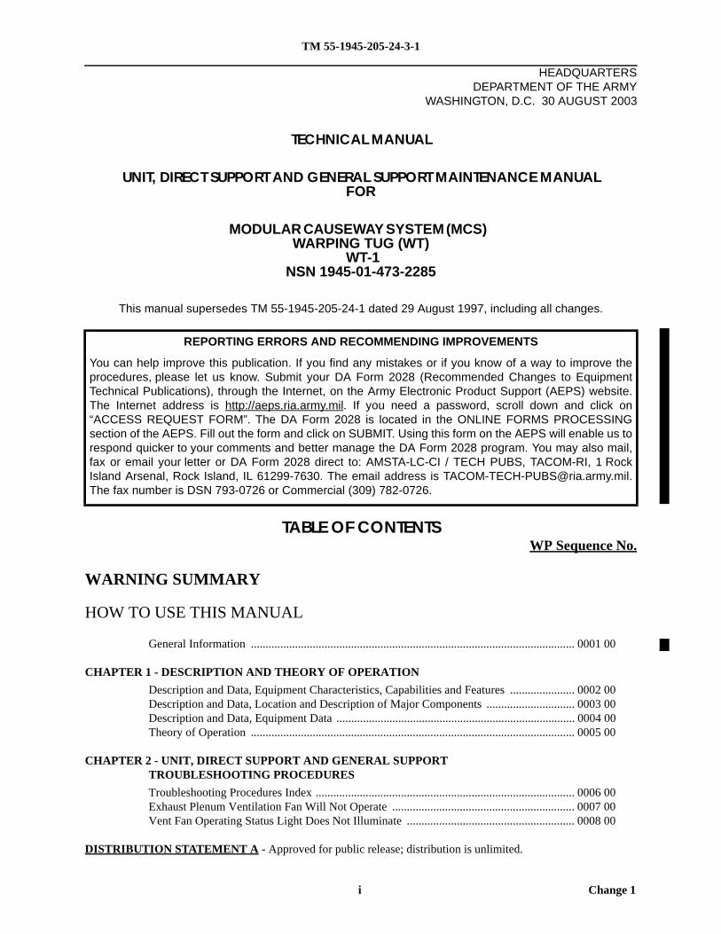
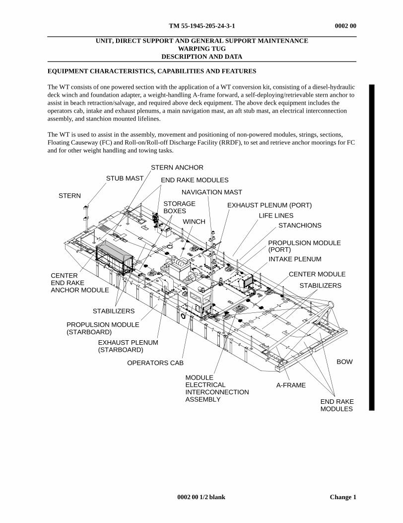
The WT consists of one powered section with the application of a WT conversion kit, consisting of a diesel-hydraulicdeck winch and foundation adapter, a weight-handling A-frame forward, a self-deploying/retrievable stern anchor toassist in beach retraction/salvage, and required above deck equipment. The above deck equipment includes theoperators cab, intake and exhaust plenums, a main navigation mast, an aft stub mast, an electrical interconnectionassembly, and stanchion mounted lifelines.
The WT is used to assist in the assembly, movement and positioning of non-powered modules, strings, sections,Floating Causeway (FC) and Roll-on/Roll-off Discharge Facility (RRDF), to set and retrieve anchor moorings for FCand for other weight handling and towing tasks.
STORAGEBOXES
PROPULSION MODULE
CENTER MODULE
STUB MAST
STERN
END RAKE MODULES
NAVIGATION MAST
LIFE LINES
(PORT)
OPERATORS CAB
EXHAUST PLENUM(STARBOARD)
PROPULSION MODULE(STARBOARD)
STERN ANCHOR
WINCH
A-FRAME
STABILIZERS
EXHAUST PLENUM (PORT)
STANCHIONS
INTAKE PLENUM
STABILIZERS
END RAKEMODULES
MODULEELECTRICALINTERCONNECTIONASSEMBLY
BOW
CENTEREND RAKEANCHOR MODULE
TM 55-1945-205-24-3-1
0003 00 1 Change 1
0003 00
OPERATOR MAINTENANCEWARPING TUG
DESCRIPTION AND DATA
LOCATION AND DESCRIPTION OF MAJOR COMPONENTS
WARPING TUG SYSTEM
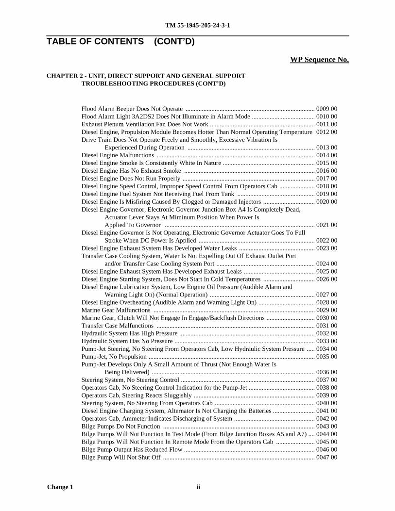
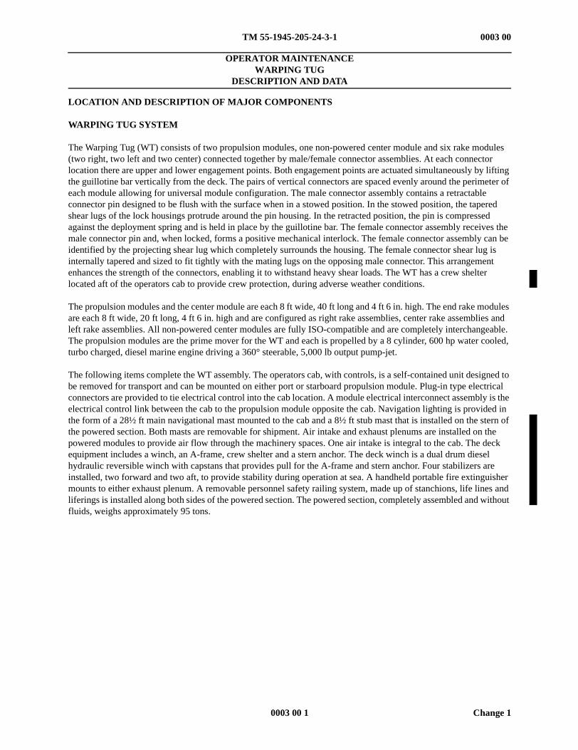
The Warping Tug (WT) consists of two propulsion modules, one non-powered center module and six rake modules(two right, two left and two center) connected together by male/female connector assemblies. At each connectorlocation there are upper and lower engagement points. Both engagement points are actuated simultaneously by liftingthe guillotine bar vertically from the deck. The pairs of vertical connectors are spaced evenly around the perimeter ofeach module allowing for universal module configuration. The male connector assembly contains a retractableconnector pin designed to be flush with the surface when in a stowed position. In the stowed position, the taperedshear lugs of the lock housings protrude around the pin housing. In the retracted position, the pin is compressedagainst the deployment spring and is held in place by the guillotine bar. The female connector assembly receives themale connector pin and, when locked, forms a positive mechanical interlock. The female connector assembly can beidentified by the projecting shear lug which completely surrounds the housing. The female connector shear lug isinternally tapered and sized to fit tightly with the mating lugs on the opposing male connector. This arrangementenhances the strength of the connectors, enabling it to withstand heavy shear loads. The WT has a crew shelterlocated aft of the operators cab to provide crew protection, during adverse weather conditions.
The propulsion modules and the center module are each 8 ft wide, 40 ft long and 4 ft 6 in. high. The end rake modulesare each 8 ft wide, 20 ft long, 4 ft 6 in. high and are configured as right rake assemblies, center rake assemblies andleft rake assemblies. All non-powered center modules are fully ISO-compatible and are completely interchangeable.The propulsion modules are the prime mover for the WT and each is propelled by a 8 cylinder, 600 hp water cooled,turbo charged, diesel marine engine driving a 360° steerable, 5,000 lb output pump-jet.
The following items complete the WT assembly. The operators cab, with controls, is a self-contained unit designed tobe removed for transport and can be mounted on either port or starboard propulsion module. Plug-in type electricalconnectors are provided to tie electrical control into the cab location. A module electrical interconnect assembly is theelectrical control link between the cab to the propulsion module opposite the cab. Navigation lighting is provided inthe form of a 28½ ft main navigational mast mounted to the cab and a 8½ ft stub mast that is installed on the stern ofthe powered section. Both masts are removable for shipment. Air intake and exhaust plenums are installed on thepowered modules to provide air flow through the machinery spaces. One air intake is integral to the cab. The deckequipment includes a winch, an A-frame, crew shelter and a stern anchor. The deck winch is a dual drum dieselhydraulic reversible winch with capstans that provides pull for the A-frame and stern anchor. Four stabilizers areinstalled, two forward and two aft, to provide stability during operation at sea. A handheld portable fire extinguishermounts to either exhaust plenum. A removable personnel safety railing system, made up of stanchions, life lines andliferings is installed along both sides of the powered section. The powered section, completely assembled and withoutfluids, weighs approximately 95 tons.
TM 55-1945-205-24-3-1
Change 1 0003 00 2
0003 00
PROPULSION MODULE
The propulsion module is the prime module in the WT and is divided into three compartments separated by watertightbulkheads with hatches. The center (machinery) compartment is the largest and contains engine cooling and exhaustcomponents, the drive train, hydraulic system and all electrical components with the exception of one bilge pump, asingle bilge pump control panel and a pressure operated switch that are located in the lazaret end compartment.
The drive train consists of a diesel engine, marine gear, transfer case and pump-jet. Guarded drive shafts connect themarine gear to the transfer case and the transfer case to the pump-jet.
The engine cooling and exhaust system consists of a sea chest (raw water inlet integral with the structure of themodule), a butterfly valve, a duplex strainer, engine raw water pump, fuel cooler, engine cooler heat exchanger,marine gear oil cooler, exhaust water shut-off valve, transfer case oil cooler, transfer case shut-off ball valve, watercooled muffler and exhaust flappers.
The hydraulic system consists of a hydraulic pump driven by the marine gear, a hydraulic motor that drives theprimary steering planetary gearbox mounted on the pump-jet, a hydraulic brake which is integral to the auxiliarysteering planetary gearbox mounted on the pump-jet, an electrically actuated way-valve with auxiliary manualcontrol, manually operated ball valve, needle valve, braking valve unit, pressure filter and a hydraulic reservoir withreturn line filter. A manual hydraulic hand pump is also provided for manual release of the hydraulic brake in case ofsystem malfunction.
PROPULSION MODULE
CENTER MODULE
STUB MAST
STERN
END RAKE MODULESNAVIGATION MAST
LIFE LINES
(PORT)
OPERATORS CAB
EXHAUST PLENUM(STARBOARD)
PROPULSION MODULE(STARBOARD)
STERN ANCHOR
WINCH
A-FRAME
STABILIZERS
EXHAUST PLENUM (PORT)
STANCHIONS
INTAKE PLENUM
STABILIZERS
END RAKEMODULES
INTERCONNECTIONASSEMBLY
MODULEELECTRICAL
BOW
ANCHORMODULE
CENTEREND RAKE
CREWSHELTER
STORAGEBOXES
TM 55-1945-205-24-3-1
0003 00 3 Change 1
0003 00
The propulsion module electrical system consists of an engine mounted alternator, six lead-acid storage batteries,propulsion module circuit breaker panel A6, battery selector switch, high current multi-battery solenoid and operatorscab 50 amp circuit breaker all located on the A10 panel, bilge pump control panel A5, single bilge pump controlpanel A7, engine junction box with emergency stop control A4, emergency stop push button, propulsion modulejunction box A3, pump-jet thruster junction box A2JB2, vent fan relay enclosure A8, pump-jet thrusterdirection/auxiliary battery junction box A9, fire detection system consisting of two thermal detectors and a thermalswitch electrically tied into the cab controls. This compartment is also equipped with five electrically operatedbilge pumps.
The aft (fuel) compartment contains the fuel tank, fuel/water separator and fuel system shutoff valves. Thiscompartment is also protected by the fire detection system. It is important to note that there are no electricalconnections, controls or operating devices in this compartment. A bilge pump is not provided in this compartment.Fire detection is accomplished by means of a probe extending through the bulkhead that separates the fuel andmachinery compartments with all electrical terminations made on the machinery compartment side. In the event offire, this compartment is flooded with CO2 upon activation of the fire suppression system.
The forward compartment (lazaret) contains the fire suppression system control and agent storage components andprovides stowage for the emergency steering assembly when not in use. This compartment is equipped with a bilgepump and is not protected by the fire suppression system.
Each propulsion module has six 3,700 gph, submersible bilge pumps; five in the machinery compartment and one inthe lazaret. The pumps are locally controlled from control stations mounted in the machinery compartment andlazaret or remotely controlled from the operators cab. The pump-jet is driven by an eight cylinder, marine dieselengine delivering 600 hp at 2,100 RPM on the output shaft. Weight of the propulsion module is approximately41,100 lb dry or 45,000 lb fully loaded. Listed below are detailed descriptions of the major components found in eachpropulsion module.
TM 55-1945-205-24-3-1
Change 1 0003 00 4
0003 00
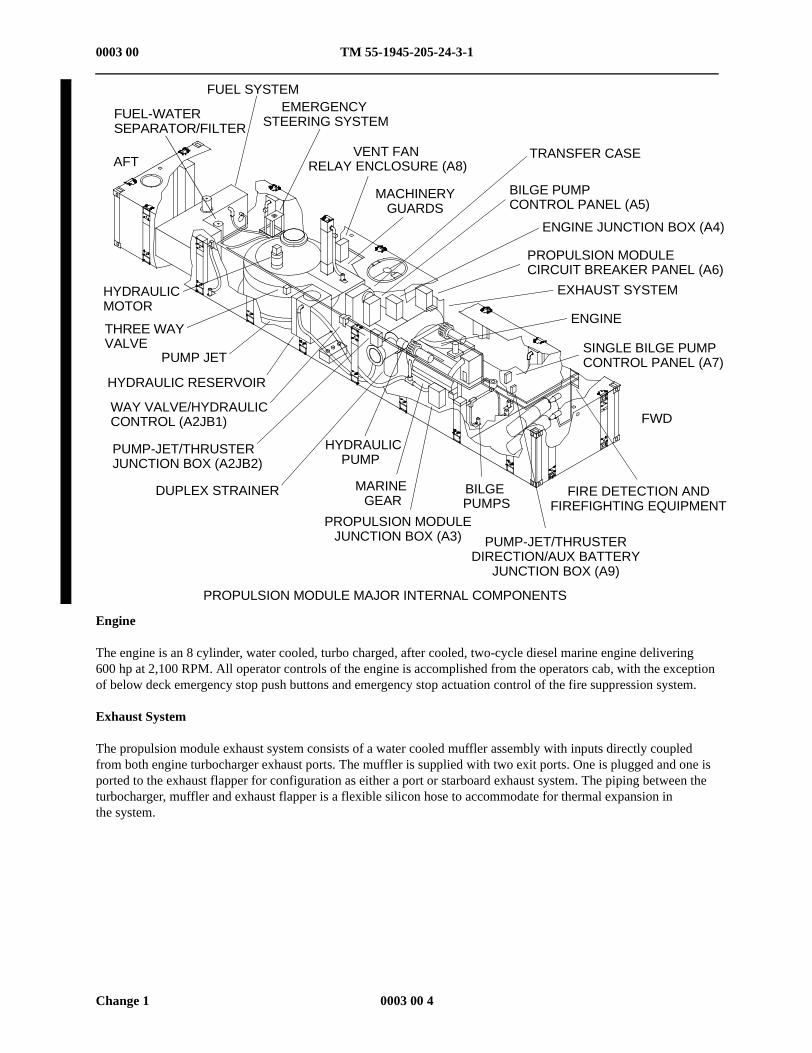
Engine
The engine is an 8 cylinder, water cooled, turbo charged, after cooled, two-cycle diesel marine engine delivering600 hp at 2,100 RPM. All operator controls of the engine is accomplished from the operators cab, with the exceptionof below deck emergency stop push buttons and emergency stop actuation control of the fire suppression system.
Exhaust System
The propulsion module exhaust system consists of a water cooled muffler assembly with inputs directly coupledfrom both engine turbocharger exhaust ports. The muffler is supplied with two exit ports. One is plugged and one isported to the exhaust flapper for configuration as either a port or starboard exhaust system. The piping between theturbocharger, muffler and exhaust flapper is a flexible silicon hose to accommodate for thermal expansion inthe system.
PROPULSION MODULE MAJOR INTERNAL COMPONENTS
FUEL-WATERSEPARATOR/FILTER
FUEL SYSTEMEMERGENCY
STEERING SYSTEM
VENT FANRELAY ENCLOSURE (A8)
MACHINERYGUARDS
ENGINE
SINGLE BILGE PUMPCONTROL PANEL (A7)
EXHAUST SYSTEM
TRANSFER CASE
BILGE PUMPCONTROL PANEL (A5)
ENGINE JUNCTION BOX (A4)
PROPULSION MODULECIRCUIT BREAKER PANEL (A6)
FIRE DETECTION ANDFIREFIGHTING EQUIPMENT
PUMP-JET/THRUSTERDIRECTION/AUX BATTERY
JUNCTION BOX (A9)
BILGEPUMPS
PROPULSION MODULEJUNCTION BOX (A3)
MARINEGEAR
DUPLEX STRAINER
PUMP-JET/THRUSTERJUNCTION BOX (A2JB2)
HYDRAULICMOTOR
THREE WAYVALVE
PUMP JET
WAY VALVE/HYDRAULICCONTROL (A2JB1)
HYDRAULIC RESERVOIR
AFT
FWD
HYDRAULICPUMP
TM 55-1945-205-24-3-1
0003 00 5 Change 1
0003 00
Fuel System
Each propulsion module is equipped with a 400 gallon stainless steel fuel tank permanently welded inside the fuelcompartment. Fuel suction and return lines are fitted with shut-off ball valves to isolate fuel to the tank when not inuse or during repairs to the fuel system. A filler neck/strainer basket, located on top of the fuel tank, is accessiblethrough a deck hatch from outside the fuel compartment. A dual purpose fuel-water separator and filter is locatednear the fuel tank in the fuel tank compartment at the rear of the module to remove water and contaminants from thediesel fuel.
Fuel-Water Separator/Filter
A dual purpose fuel-water separator and filter is located near the fuel tank in the fuel tank compartment at the rear ofthe module. Its main function is to remove water and contaminants from the diesel fuel.
Marine Gear
The marine gear provides the capability to reverse the directional rotation of the other drive train components makingit possible to backflush the pump-jet. It is mounted directly to the flywheel housing of the diesel engine. Thetransmission is equipped with an integral hydraulic system consisting of a pump, shifting valve and internal hydrauliccylinders. The pump utilizes the transmission lubricating oil to operate hydraulic cylinders, which shifts the gears tothe backflush, neutral or engaged configurations. The shifting valve is solenoid actuated from a toggle control switchin the operators cab. In addition to powering the shifting cylinders, the pump also circulates case oil through an oilcooler that is plumbed into the engine raw water cooling system. In the event of electrical power loss to the marinegear shifting solenoids, an emergency engagement capability is provided for the marine gear by replacing a shiftingvalve solenoid with an emergency lock-up plug that locks the marine gear transmission gearing. The lock-up plugis used to provide independent forward or backflush capabilities and is mounted externally to the shifting valvesolenoid housing.
Transfer Case
The transfer case compensates for offset alignment between the output flange of the marine gear and the input flangeof the pump-jet. It has a 1:1 gear ratio, utilizing spur gears throughout, and is equipped with an oil pump thatcirculates lubricating oil from its gear case through an oil cooler plumbed off of the engine raw water cooling systemand back to the top of the transfer case to lubricate the upper gearing. The transfer case is connected to the marinegear and the pump-jet via drive shafts.
Machinery Guards
Removable metal machinery guards cover the drive shafts, engine flywheel and alternator belt to protect personnelfrom contact with rotating parts.
Pump-Jet
Each propulsion module is equipped with a 360° steerable pump-jet propulsion unit capable of delivering 5,000 lb ofthrust. The pump-jet works on the principal of a rotary pump and consists of a drive shaft that drives an uppergearbox assembly which drives an impeller. Water is sucked into the pump-jet through a feeding funnel on the bottomof the module and fed into the enclosed pressure casing, whose bottom plate is provided with three systematicallyarranged outlet nozzles from which water is ejected at a 13° angle. A hydraulic steering motor drives a spur gearthrough a planetary gearbox to rotate the pressure casing and steering nozzles, located on the bottom, in both sensesof rotation without limitation. A second planetary gearbox is provided to facilitate emergency steering. Theemergency steering control stand is mounted above deck and interfaces with the through shaft of the planetarygearbox. The emergency steering gearbox contains a spring set, hydraulically released disc brake. The brakemaintains the position of the steering nozzle until rotation is called for by the operator. In the event of hydraulicsystem failure, the brake can be released via the hydraulic hand pump to facilitate emergency steering.