Embed Size (px)
Citation preview
MCS 2000
TM
Mobile FM RadioModels I, II, and III
Detailed User Reference Guide
Computer Software Copyrights
The Motorola products described in this instruction manual include copyrighted Motorola computer programs stored in semiconductor memories or other mediums. Laws in the United States and other countries preserve for Motorola certain exclusive rights for copyrighted computer programs, including the exclusive right to copy or reproduce in any form a copyrighted computer program. Accordingly, any copyrighted Motorola computer programs contained in the Motorola products described in this instruction manual may not be copied or reproduced in any manner without the express written permission of Motorola. Furthermore, the purchase of Motorola products shall not be deemed to grant either directly or by implication, estopped or otherwise, any license under the copyrights, patents, or patent applications of Motorola, except for the normal non-exclusive, royalty fee license to use that arises by operation of law in the sale of a product.
,
Motorola, MDC-1200, MCS 2000, Spectra, FLASHport, SMARTNET,
Single Tone, StartSite, Private-Line, Digital Private-Line, Call Alert, Private
Conversation, SmartZone, and ASTRO are trademarks of Motorola, Inc.
IBM, AT, PC XT, Personal Computer AT, Personal Computer XT, and Personal System/
2 are trademarks of International Business Machines, Inc.
© 1996 by Motorola, Inc.Radio Products Group8000 West Sunrise Blvd.Ft. Lauderdale, FL 33322
Printed in U.S.A. Part NumberAll Rights Reserved. 6881080C35-O
Important Notes
Radio Programming Notes
Native Language Display
Any one of the following six languages can be programmed for your radio displays via Radio Service Software:
- English - French- Spanish - German- Italian - Portuguese
When a specific language has been programmed, all of your radio displays will be shown in the selected language.
All mobile radios are shipped with English as the default display language. This manual uses the English displays for all references. For a cross-reference to other language displays, refer to Appendix A.
Menu Items
Menu items are programmed by Radio Service Software (RSS). Some of the menu items referred to in this user guide may not appear in your list of menu items, and others may use different words from those referred to here. See your Radio System Manager for information on what menu items are programmed into your radio.
Programmable Buttons
Every mode can be programmed by RSS with a unique set of features. If a feature is not programmed on your current mode, a “bad key” tone will sound when you press the feature button. See your Radio System Manager for information on functions programmed for each programmable button.
Buttons may be programmed via RSS for features different from those listed in this manual. Contact your Radio System Manager for more information.
Continued on next page
Important Notes
Accessory Connector Notes
The accessory connector plug must be inserted into the accessory connector socket on the bottom of your radio to prevent inadvertent emergency operation. Refer to the information on the Accessory Connector on page 10 for additional information.
Always turn off the radio before removing any accessories; otherwise, damage to the radio may occur.
!C a u t i o n
v
Contents
Contents . . . . . . . . . . . . . . . . . . . . . . . . . . . . . . . . . . . . . . . . . . . . . . . . . . . . . . v
Feature Finder . . . . . . . . . . . . . . . . . . . . . . . . . . . . . . . . . . . . . . . . . . . . . . . . . 1
About This User Guide . . . . . . . . . . . . . . . . . . . . . . . . . . . . . . . . . . . . . . . . . . 3
How To Use This Guide. . . . . . . . . . . . . . . . . . . . . . . . . . . . . . . . . . . . . . . . . . . . . . . .3Notational Conventions . . . . . . . . . . . . . . . . . . . . . . . . . . . . . . . . . . . . . . . . . . . . . . .3Notes, Cautions, Warnings, Dangers . . . . . . . . . . . . . . . . . . . . . . . . . . . . . . . . . . . . .4
1 - MCS 2000 Overview . . . . . . . . . . . . . . . . . . . . . . . . . . . . . . . . . . . . . . . . . . . 5
Product Features . . . . . . . . . . . . . . . . . . . . . . . . . . . . . . . . . . . . . . . . . . . . . . . . . . . . .6Model Differences . . . . . . . . . . . . . . . . . . . . . . . . . . . . . . . . . . . . . . . . . . . . . . . . . . . .7Mounting Options. . . . . . . . . . . . . . . . . . . . . . . . . . . . . . . . . . . . . . . . . . . . . . . . . . . .8Feature Programming . . . . . . . . . . . . . . . . . . . . . . . . . . . . . . . . . . . . . . . . . . . . . . . . .8Accessories . . . . . . . . . . . . . . . . . . . . . . . . . . . . . . . . . . . . . . . . . . . . . . . . . . . . . . . . . .8
Standard Accessories. . . . . . . . . . . . . . . . . . . . . . . . . . . . . . . . . . . . . . . . . . . . . . . .8Microphone Accessories . . . . . . . . . . . . . . . . . . . . . . . . . . . . . . . . . . . . . . . . . . . . .9Accessory Connector . . . . . . . . . . . . . . . . . . . . . . . . . . . . . . . . . . . . . . . . . . . . . .10
2 - Radio Controls. . . . . . . . . . . . . . . . . . . . . . . . . . . . . . . . . . . . . . . . . . . . . . 11
MCS 2000 Controls . . . . . . . . . . . . . . . . . . . . . . . . . . . . . . . . . . . . . . . . . . . . . . . . . .12Control Buttons. . . . . . . . . . . . . . . . . . . . . . . . . . . . . . . . . . . . . . . . . . . . . . . . . . . . .14Display. . . . . . . . . . . . . . . . . . . . . . . . . . . . . . . . . . . . . . . . . . . . . . . . . . . . . . . . . . . .16Display Annunciators . . . . . . . . . . . . . . . . . . . . . . . . . . . . . . . . . . . . . . . . . . . . . . . .17
3 - Basic Radio Operation . . . . . . . . . . . . . . . . . . . . . . . . . . . . . . . . . . . . . . . 19
Turning the Radio On and Off . . . . . . . . . . . . . . . . . . . . . . . . . . . . . . . . . . . . . . . . .20Test Mode . . . . . . . . . . . . . . . . . . . . . . . . . . . . . . . . . . . . . . . . . . . . . . . . . . . . . . .21
Setting Receiver Volume . . . . . . . . . . . . . . . . . . . . . . . . . . . . . . . . . . . . . . . . . . . . . .21Selecting Radio Features . . . . . . . . . . . . . . . . . . . . . . . . . . . . . . . . . . . . . . . . . . . . . .22
Button Selection . . . . . . . . . . . . . . . . . . . . . . . . . . . . . . . . . . . . . . . . . . . . . . . . . .22Menu Selection. . . . . . . . . . . . . . . . . . . . . . . . . . . . . . . . . . . . . . . . . . . . . . . . . . .23Radio Modes . . . . . . . . . . . . . . . . . . . . . . . . . . . . . . . . . . . . . . . . . . . . . . . . . . . . .23
Zone/Channel Assignment . . . . . . . . . . . . . . . . . . . . . . . . . . . . . . . . . . . . . . . . . . . .24Selecting Zones . . . . . . . . . . . . . . . . . . . . . . . . . . . . . . . . . . . . . . . . . . . . . . . . . . .25Selecting Channels . . . . . . . . . . . . . . . . . . . . . . . . . . . . . . . . . . . . . . . . . . . . . . . .25Rotary Selector . . . . . . . . . . . . . . . . . . . . . . . . . . . . . . . . . . . . . . . . . . . . . . . . . . .26
Selecting the Home Mode . . . . . . . . . . . . . . . . . . . . . . . . . . . . . . . . . . . . . . . . . . . . .26
Contents
vi
Adjusting Display Brightness . . . . . . . . . . . . . . . . . . . . . . . . . . . . . . . . . . . . . . . . . .26Setting Transmitter Power Level . . . . . . . . . . . . . . . . . . . . . . . . . . . . . . . . . . . . . . . .27External Alarm . . . . . . . . . . . . . . . . . . . . . . . . . . . . . . . . . . . . . . . . . . . . . . . . . . . . .28
User Enabled External Alarm . . . . . . . . . . . . . . . . . . . . . . . . . . . . . . . . . . . . . . . .28Automatically Activated External Alarm . . . . . . . . . . . . . . . . . . . . . . . . . . . . . . .28
Using the Time-out Timer. . . . . . . . . . . . . . . . . . . . . . . . . . . . . . . . . . . . . . . . . . . . .29Alert Tones . . . . . . . . . . . . . . . . . . . . . . . . . . . . . . . . . . . . . . . . . . . . . . . . . . . . . . . .29
Keypad Tone Muting . . . . . . . . . . . . . . . . . . . . . . . . . . . . . . . . . . . . . . . . . . . . . .29
4 - Conventional Operation . . . . . . . . . . . . . . . . . . . . . . . . . . . . . . . . . . . . . .31
Monitor . . . . . . . . . . . . . . . . . . . . . . . . . . . . . . . . . . . . . . . . . . . . . . . . . . . . . . . . . . .32Transmitting . . . . . . . . . . . . . . . . . . . . . . . . . . . . . . . . . . . . . . . . . . . . . . . . . . . . . . .32
Private Line Codes . . . . . . . . . . . . . . . . . . . . . . . . . . . . . . . . . . . . . . . . . . . . . . . .33Smart Push-to-Talk. . . . . . . . . . . . . . . . . . . . . . . . . . . . . . . . . . . . . . . . . . . . . . . .33Quick-Key Override . . . . . . . . . . . . . . . . . . . . . . . . . . . . . . . . . . . . . . . . . . . . . . .34
Talkaround . . . . . . . . . . . . . . . . . . . . . . . . . . . . . . . . . . . . . . . . . . . . . . . . . . . . . . . .34Selective Call . . . . . . . . . . . . . . . . . . . . . . . . . . . . . . . . . . . . . . . . . . . . . . . . . . . . . . .35
Transmitting a Selective Call . . . . . . . . . . . . . . . . . . . . . . . . . . . . . . . . . . . . . . . .35Receiving a Selective Call . . . . . . . . . . . . . . . . . . . . . . . . . . . . . . . . . . . . . . . . . . .36
Call Alert/Page. . . . . . . . . . . . . . . . . . . . . . . . . . . . . . . . . . . . . . . . . . . . . . . . . . . . . .37Transmitting a Call Alert/Page. . . . . . . . . . . . . . . . . . . . . . . . . . . . . . . . . . . . . . .37Receiving a Call Alert Page. . . . . . . . . . . . . . . . . . . . . . . . . . . . . . . . . . . . . . . . . .38
Quick Call II . . . . . . . . . . . . . . . . . . . . . . . . . . . . . . . . . . . . . . . . . . . . . . . . . . . . . . .38GE Star. . . . . . . . . . . . . . . . . . . . . . . . . . . . . . . . . . . . . . . . . . . . . . . . . . . . . . . . . . . .38Singletone Repeater Access . . . . . . . . . . . . . . . . . . . . . . . . . . . . . . . . . . . . . . . . . . . .39Telephone Interconnect . . . . . . . . . . . . . . . . . . . . . . . . . . . . . . . . . . . . . . . . . . . . . .39
5 - Trunking Operation. . . . . . . . . . . . . . . . . . . . . . . . . . . . . . . . . . . . . . . . . .41
Transmitting . . . . . . . . . . . . . . . . . . . . . . . . . . . . . . . . . . . . . . . . . . . . . . . . . . . . . . .42Out of Range . . . . . . . . . . . . . . . . . . . . . . . . . . . . . . . . . . . . . . . . . . . . . . . . . . . .43
Private Call . . . . . . . . . . . . . . . . . . . . . . . . . . . . . . . . . . . . . . . . . . . . . . . . . . . . . . . .43Private Call I and II . . . . . . . . . . . . . . . . . . . . . . . . . . . . . . . . . . . . . . . . . . . . . . .43Enhanced Private Call . . . . . . . . . . . . . . . . . . . . . . . . . . . . . . . . . . . . . . . . . . . . .43Transmitting a Private Call . . . . . . . . . . . . . . . . . . . . . . . . . . . . . . . . . . . . . . . . .44Receiving a Private Call . . . . . . . . . . . . . . . . . . . . . . . . . . . . . . . . . . . . . . . . . . . .45
Call Alert/Page. . . . . . . . . . . . . . . . . . . . . . . . . . . . . . . . . . . . . . . . . . . . . . . . . . . . . .47Transmitting a Call Alert/Page. . . . . . . . . . . . . . . . . . . . . . . . . . . . . . . . . . . . . . .47Receiving a Call Alert/Page . . . . . . . . . . . . . . . . . . . . . . . . . . . . . . . . . . . . . . . . .48
One-Touch Button . . . . . . . . . . . . . . . . . . . . . . . . . . . . . . . . . . . . . . . . . . . . . . . . . .48Dynamic Regrouping . . . . . . . . . . . . . . . . . . . . . . . . . . . . . . . . . . . . . . . . . . . . . . . .49
Receiving a Dynamic Regrouping Assignment . . . . . . . . . . . . . . . . . . . . . . . . . .49Select Enabled and Disabled . . . . . . . . . . . . . . . . . . . . . . . . . . . . . . . . . . . . . . . .49
Contents
vii
Selecting an Unprogrammed Dynamic Mode . . . . . . . . . . . . . . . . . . . . . . . . . . .50Requesting Dynamic Regrouping. . . . . . . . . . . . . . . . . . . . . . . . . . . . . . . . . . . . .50
Automatic Multiple-Site Switching . . . . . . . . . . . . . . . . . . . . . . . . . . . . . . . . . . . . . .51Manually Changing Sites . . . . . . . . . . . . . . . . . . . . . . . . . . . . . . . . . . . . . . . . . . .51RSSI Text Display . . . . . . . . . . . . . . . . . . . . . . . . . . . . . . . . . . . . . . . . . . . . . . . . .51Inhibiting Automatic Site Switching . . . . . . . . . . . . . . . . . . . . . . . . . . . . . . . . . .52
SmartZone Features . . . . . . . . . . . . . . . . . . . . . . . . . . . . . . . . . . . . . . . . . . . . . . . . . .53Busy Override In a SmartZone System. . . . . . . . . . . . . . . . . . . . . . . . . . . . . . . . .53Site Trunking . . . . . . . . . . . . . . . . . . . . . . . . . . . . . . . . . . . . . . . . . . . . . . . . . . . .54Full Spectrum Scan . . . . . . . . . . . . . . . . . . . . . . . . . . . . . . . . . . . . . . . . . . . . . . . .54
Voice On Control Operation. . . . . . . . . . . . . . . . . . . . . . . . . . . . . . . . . . . . . . . . . . .54Trunked Type II Announcement. . . . . . . . . . . . . . . . . . . . . . . . . . . . . . . . . . . . . . . .54Failsoft . . . . . . . . . . . . . . . . . . . . . . . . . . . . . . . . . . . . . . . . . . . . . . . . . . . . . . . . . . . .55Telephone Interconnect . . . . . . . . . . . . . . . . . . . . . . . . . . . . . . . . . . . . . . . . . . . . . .56
Receiving a Telephone Call . . . . . . . . . . . . . . . . . . . . . . . . . . . . . . . . . . . . . . . . .56Calling the Last Sent Number . . . . . . . . . . . . . . . . . . . . . . . . . . . . . . . . . . . . . . .57Calling via a Phone List . . . . . . . . . . . . . . . . . . . . . . . . . . . . . . . . . . . . . . . . . . . .57Calling via Direct Keypad Entry. . . . . . . . . . . . . . . . . . . . . . . . . . . . . . . . . . . . . .58Correcting Numbers . . . . . . . . . . . . . . . . . . . . . . . . . . . . . . . . . . . . . . . . . . . . . . .58Editing the Phone List . . . . . . . . . . . . . . . . . . . . . . . . . . . . . . . . . . . . . . . . . . . . .58Phone Not Available. . . . . . . . . . . . . . . . . . . . . . . . . . . . . . . . . . . . . . . . . . . . . . .58Phone Busy Tone . . . . . . . . . . . . . . . . . . . . . . . . . . . . . . . . . . . . . . . . . . . . . . . . .59Exiting Phone Mode. . . . . . . . . . . . . . . . . . . . . . . . . . . . . . . . . . . . . . . . . . . . . . .59
6 - Features Common to Conventional and Trunked Operation. . . . . . . . 61
Emergency . . . . . . . . . . . . . . . . . . . . . . . . . . . . . . . . . . . . . . . . . . . . . . . . . . . . . . . . .62Emergency Alarm . . . . . . . . . . . . . . . . . . . . . . . . . . . . . . . . . . . . . . . . . . . . . . . . .62Emergency Call. . . . . . . . . . . . . . . . . . . . . . . . . . . . . . . . . . . . . . . . . . . . . . . . . . .63Canceling Emergency Calls . . . . . . . . . . . . . . . . . . . . . . . . . . . . . . . . . . . . . . . . .63Silent Emergency Alarm . . . . . . . . . . . . . . . . . . . . . . . . . . . . . . . . . . . . . . . . . . . .63Special Emergency Considerations . . . . . . . . . . . . . . . . . . . . . . . . . . . . . . . . . . .64Emergency Call Received Operation . . . . . . . . . . . . . . . . . . . . . . . . . . . . . . . . . .65Emergency With Voice to Follow . . . . . . . . . . . . . . . . . . . . . . . . . . . . . . . . . . . .65
Transmission Received - Acknowledge/No Acknowledge. . . . . . . . . . . . . . . . . . . . .66Scanning . . . . . . . . . . . . . . . . . . . . . . . . . . . . . . . . . . . . . . . . . . . . . . . . . . . . . . . . . .67
Types of Scan Lists . . . . . . . . . . . . . . . . . . . . . . . . . . . . . . . . . . . . . . . . . . . . . . . .67Scan Indicators . . . . . . . . . . . . . . . . . . . . . . . . . . . . . . . . . . . . . . . . . . . . . . . . . . .68Turning Scan On and Off. . . . . . . . . . . . . . . . . . . . . . . . . . . . . . . . . . . . . . . . . . .69Auto-Scan . . . . . . . . . . . . . . . . . . . . . . . . . . . . . . . . . . . . . . . . . . . . . . . . . . . . . . .69Scan Hang-Time . . . . . . . . . . . . . . . . . . . . . . . . . . . . . . . . . . . . . . . . . . . . . . . . . .70Nuisance Delete . . . . . . . . . . . . . . . . . . . . . . . . . . . . . . . . . . . . . . . . . . . . . . . . . .70Recall . . . . . . . . . . . . . . . . . . . . . . . . . . . . . . . . . . . . . . . . . . . . . . . . . . . . . . . . . .70
Contents
viii
Viewing a Scan List . . . . . . . . . . . . . . . . . . . . . . . . . . . . . . . . . . . . . . . . . . . . . . .71Hang-up Box . . . . . . . . . . . . . . . . . . . . . . . . . . . . . . . . . . . . . . . . . . . . . . . . . . . .71
Editing Radio Lists. . . . . . . . . . . . . . . . . . . . . . . . . . . . . . . . . . . . . . . . . . . . . . . . . . .72Editing the Scan List . . . . . . . . . . . . . . . . . . . . . . . . . . . . . . . . . . . . . . . . . . . . . .72Editing the Call List . . . . . . . . . . . . . . . . . . . . . . . . . . . . . . . . . . . . . . . . . . . . . . .73Editing the Phone List . . . . . . . . . . . . . . . . . . . . . . . . . . . . . . . . . . . . . . . . . . . . .74
Status/Message Transmission . . . . . . . . . . . . . . . . . . . . . . . . . . . . . . . . . . . . . . . . . .75Handset Operation . . . . . . . . . . . . . . . . . . . . . . . . . . . . . . . . . . . . . . . . . . . . . . . . . .76
7 - Secure Operation . . . . . . . . . . . . . . . . . . . . . . . . . . . . . . . . . . . . . . . . . . . .77
Introduction . . . . . . . . . . . . . . . . . . . . . . . . . . . . . . . . . . . . . . . . . . . . . . . . . . . . . . .78Quick Reference . . . . . . . . . . . . . . . . . . . . . . . . . . . . . . . . . . . . . . . . . . . . . . . . . . . .78Tones . . . . . . . . . . . . . . . . . . . . . . . . . . . . . . . . . . . . . . . . . . . . . . . . . . . . . . . . . . . . .79Basic SECURENET Operation . . . . . . . . . . . . . . . . . . . . . . . . . . . . . . . . . . . . . . . . . .80
Radio On/Off . . . . . . . . . . . . . . . . . . . . . . . . . . . . . . . . . . . . . . . . . . . . . . . . . . . .80Monitoring . . . . . . . . . . . . . . . . . . . . . . . . . . . . . . . . . . . . . . . . . . . . . . . . . . . . . .80Receiving . . . . . . . . . . . . . . . . . . . . . . . . . . . . . . . . . . . . . . . . . . . . . . . . . . . . . . .80Transmitting. . . . . . . . . . . . . . . . . . . . . . . . . . . . . . . . . . . . . . . . . . . . . . . . . . . . .80
SECURENET Keyloading and Key Erase . . . . . . . . . . . . . . . . . . . . . . . . . . . . . . . . . .82Secure Operation with Other Radio Features . . . . . . . . . . . . . . . . . . . . . . . . . . . . . .84
Smart PTT . . . . . . . . . . . . . . . . . . . . . . . . . . . . . . . . . . . . . . . . . . . . . . . . . . . . . . .84Trunked Emergency Operation . . . . . . . . . . . . . . . . . . . . . . . . . . . . . . . . . . . . . .84Trunked Private Conversation II . . . . . . . . . . . . . . . . . . . . . . . . . . . . . . . . . . . . .84Trunked Enhanced Private Conversation . . . . . . . . . . . . . . . . . . . . . . . . . . . . . .84Trunked Telephone Operation . . . . . . . . . . . . . . . . . . . . . . . . . . . . . . . . . . . . . .84Dynamic Regrouping . . . . . . . . . . . . . . . . . . . . . . . . . . . . . . . . . . . . . . . . . . . . . .85Failsoft Operation. . . . . . . . . . . . . . . . . . . . . . . . . . . . . . . . . . . . . . . . . . . . . . . . .85
8 - Operator Troubleshooting. . . . . . . . . . . . . . . . . . . . . . . . . . . . . . . . . . . . .87
9 - Safety Information. . . . . . . . . . . . . . . . . . . . . . . . . . . . . . . . . . . . . . . . . . .89
General Safety Information . . . . . . . . . . . . . . . . . . . . . . . . . . . . . . . . . . . . . . . . . . .90Radio Installation Safety . . . . . . . . . . . . . . . . . . . . . . . . . . . . . . . . . . . . . . . . . . . . . .91
Installation Location . . . . . . . . . . . . . . . . . . . . . . . . . . . . . . . . . . . . . . . . . . . . . .91Installation Connections . . . . . . . . . . . . . . . . . . . . . . . . . . . . . . . . . . . . . . . . . . .91
Important Electromagnetic Emission Information . . . . . . . . . . . . . . . . . . . . . . . . .92Control Station Operation . . . . . . . . . . . . . . . . . . . . . . . . . . . . . . . . . . . . . . . . . .92
Operational Safety. . . . . . . . . . . . . . . . . . . . . . . . . . . . . . . . . . . . . . . . . . . . . . . . . . .93Converted Mobile Equipment . . . . . . . . . . . . . . . . . . . . . . . . . . . . . . . . . . . . . . . . .94Airbag Warning . . . . . . . . . . . . . . . . . . . . . . . . . . . . . . . . . . . . . . . . . . . . . . . . . . . . .94
A - Native Languages . . . . . . . . . . . . . . . . . . . . . . . . . . . . . . . . . . . . . . . . . . . .95
Contents
ix
B - Operational Flowcharts . . . . . . . . . . . . . . . . . . . . . . . . . . . . . . . . . . . . . 101
B1.1 - PHONE: Direct Entry . . . . . . . . . . . . . . . . . . . . . . . . . . . . . . . . . . . . . . . .102B1.2 - PHONE: List Scrolling . . . . . . . . . . . . . . . . . . . . . . . . . . . . . . . . . . . . . . .103B1.3 - PHONE: List Editing. . . . . . . . . . . . . . . . . . . . . . . . . . . . . . . . . . . . . . . . .104B2.1 - MDC SELECTIVE CALL/PAGE: Direct Entry . . . . . . . . . . . . . . . . . . . . . .105B2.2 - MDC SELECTIVE CALL/PAGE: List Scrolling . . . . . . . . . . . . . . . . . . . . .106B2.3 - MDC SELECTIVE CALL/PAGE: List Editing. . . . . . . . . . . . . . . . . . . . . . .107B3.1 - TRUNKING PRIVATE CALL/PAGE: Direct Entry . . . . . . . . . . . . . . . . . . .108B3.2 - TRUNKING PRIVATE CALL/PAGE: List Scrolling . . . . . . . . . . . . . . . . . .109B3.3 - TRUNKING PRIVATE CALL/PAGE: List Editing . . . . . . . . . . . . . . . . . . .110B4.1 - SCAN: List Editing . . . . . . . . . . . . . . . . . . . . . . . . . . . . . . . . . . . . . . . . . .111

Contents
x
1
Feature Finder
Use this alphabetized list of radio features to quickly find the operating instructions you need.
Feature Page
Alert Tones . . . . . . . . . . . . . . . . . . . . . . . . . . . . . . . . . . . . . . . . . . . . . . . . . . . . . 29Announcement, Type II, Trunked . . . . . . . . . . . . . . . . . . . . . . . . . . . . . . . . . . . 54Automatic Multiple Site Switching . . . . . . . . . . . . . . . . . . . . . . . . . . . . . . . . . . 51Autoscan . . . . . . . . . . . . . . . . . . . . . . . . . . . . . . . . . . . . . . . . . . . . . . . . . . . . . . 69Busy Override (SmartZone) . . . . . . . . . . . . . . . . . . . . . . . . . . . . . . . . . . . . . . . . 53Call Alert Page, Conventional . . . . . . . . . . . . . . . . . . . . . . . . . . . . . . . . . . . . . . 38Call Alert Page, Trunking. . . . . . . . . . . . . . . . . . . . . . . . . . . . . . . . . . . . . . . . . . 47Call List . . . . . . . . . . . . . . . . . . . . . . . . . . . . . . . . . . . . . . . . . . . . . . . . . . . . . . . 73Display Brightness Adjustment . . . . . . . . . . . . . . . . . . . . . . . . . . . . . . . . . . . . . 26Dynamic Regrouping, Secure. . . . . . . . . . . . . . . . . . . . . . . . . . . . . . . . . . . . . . . 85Dynamic Regrouping, Trunked . . . . . . . . . . . . . . . . . . . . . . . . . . . . . . . . . . . . . 49Emergency Alarm. . . . . . . . . . . . . . . . . . . . . . . . . . . . . . . . . . . . . . . . . . . . . . . . 62Emergency Alarm, Silent . . . . . . . . . . . . . . . . . . . . . . . . . . . . . . . . . . . . . . . . . . 63Emergency Call Received. . . . . . . . . . . . . . . . . . . . . . . . . . . . . . . . . . . . . . . . . . 65Emergency Call, Canceling . . . . . . . . . . . . . . . . . . . . . . . . . . . . . . . . . . . . . . . . 63Emergency, SECURENET, Trunked. . . . . . . . . . . . . . . . . . . . . . . . . . . . . . . . . . . 84Emergency With Voice to Follow . . . . . . . . . . . . . . . . . . . . . . . . . . . . . . . . . . . 65External Alarm . . . . . . . . . . . . . . . . . . . . . . . . . . . . . . . . . . . . . . . . . . . . . . . . . . 28Failsoft, Trunking. . . . . . . . . . . . . . . . . . . . . . . . . . . . . . . . . . . . . . . . . . . . . . . . 55Failsoft, SECURENET . . . . . . . . . . . . . . . . . . . . . . . . . . . . . . . . . . . . . . . . . . . . . 85GE Star . . . . . . . . . . . . . . . . . . . . . . . . . . . . . . . . . . . . . . . . . . . . . . . . . . . . . . . . 38Handset . . . . . . . . . . . . . . . . . . . . . . . . . . . . . . . . . . . . . . . . . . . . . . . . . . . . . . . 76Hang-Up Box . . . . . . . . . . . . . . . . . . . . . . . . . . . . . . . . . . . . . . . . . . . . . . . . . . . 71Home Mode Selection . . . . . . . . . . . . . . . . . . . . . . . . . . . . . . . . . . . . . . . . . . . . 26Keypad Tone Mute . . . . . . . . . . . . . . . . . . . . . . . . . . . . . . . . . . . . . . . . . . . . . . . 29Keyloading and Key Erase (SECURENET) . . . . . . . . . . . . . . . . . . . . . . . . . . . . . 82Last Called Number Recall. . . . . . . . . . . . . . . . . . . . . . . . . . . . . . . . . . . . . . . . . 57Monitor . . . . . . . . . . . . . . . . . . . . . . . . . . . . . . . . . . . . . . . . . . . . . . . . . . . . . . . 32Multiple-Site Switching, Automatic. . . . . . . . . . . . . . . . . . . . . . . . . . . . . . . . . . 51Nuisance Delete . . . . . . . . . . . . . . . . . . . . . . . . . . . . . . . . . . . . . . . . . . . . . . . . . 70One-Touch Button . . . . . . . . . . . . . . . . . . . . . . . . . . . . . . . . . . . . . . . . . . . . . . . 48Out of Range . . . . . . . . . . . . . . . . . . . . . . . . . . . . . . . . . . . . . . . . . . . . . . . . . . . 43
Feature Finder
2
Page, Call Alert, Conventional . . . . . . . . . . . . . . . . . . . . . . . . . . . . . . . . . . . . . 37Page, Call Alert, Trunking . . . . . . . . . . . . . . . . . . . . . . . . . . . . . . . . . . . . . . . . . 47Phone List Editing . . . . . . . . . . . . . . . . . . . . . . . . . . . . . . . . . . . . . . . . . . . . . . . 74Phone Out of Range Tone . . . . . . . . . . . . . . . . . . . . . . . . . . . . . . . . . . . . . . . . . 58Pre-Stored Number Calling . . . . . . . . . . . . . . . . . . . . . . . . . . . . . . . . . . . . . . . . 57Private Call. . . . . . . . . . . . . . . . . . . . . . . . . . . . . . . . . . . . . . . . . . . . . . . . . . . . . 43Private Conversation, Enhanced, Trunked . . . . . . . . . . . . . . . . . . . . . . . . . . . . 43Private Conversation I and II, Trunked . . . . . . . . . . . . . . . . . . . . . . . . . . . . . . . 43Private Line Codes . . . . . . . . . . . . . . . . . . . . . . . . . . . . . . . . . . . . . . . . . . . . . . . 33Quick Call II. . . . . . . . . . . . . . . . . . . . . . . . . . . . . . . . . . . . . . . . . . . . . . . . . . . . 38Quick-Key Override . . . . . . . . . . . . . . . . . . . . . . . . . . . . . . . . . . . . . . . . . . . . . . 34Recall . . . . . . . . . . . . . . . . . . . . . . . . . . . . . . . . . . . . . . . . . . . . . . . . . . . . . . . . . 70Recall Last Called Number. . . . . . . . . . . . . . . . . . . . . . . . . . . . . . . . . . . . . . . . . 57Repeater Access, Singletone. . . . . . . . . . . . . . . . . . . . . . . . . . . . . . . . . . . . . . . . 39RSSI Text Display . . . . . . . . . . . . . . . . . . . . . . . . . . . . . . . . . . . . . . . . . . . . . . . . 51Scanning . . . . . . . . . . . . . . . . . . . . . . . . . . . . . . . . . . . . . . . . . . . . . . . . . . . . . . 67Scan List Editing . . . . . . . . . . . . . . . . . . . . . . . . . . . . . . . . . . . . . . . . . . . . . . . . 72Scan List Viewing. . . . . . . . . . . . . . . . . . . . . . . . . . . . . . . . . . . . . . . . . . . . . . . . 71Scan, Full Spectrum . . . . . . . . . . . . . . . . . . . . . . . . . . . . . . . . . . . . . . . . . . . . . . 54Secure Operation . . . . . . . . . . . . . . . . . . . . . . . . . . . . . . . . . . . . . . . . . . . . . . . . 80Selective Call, Conventional . . . . . . . . . . . . . . . . . . . . . . . . . . . . . . . . . . . . . . . 35Singletone Repeater Access . . . . . . . . . . . . . . . . . . . . . . . . . . . . . . . . . . . . . . . . 39Site Locked/Unlocked . . . . . . . . . . . . . . . . . . . . . . . . . . . . . . . . . . . . . . . . . . . . 52Site Trunking . . . . . . . . . . . . . . . . . . . . . . . . . . . . . . . . . . . . . . . . . . . . . . . . . . . 54Smart Push-To-Talk, Conventional . . . . . . . . . . . . . . . . . . . . . . . . . . . . . . . . . . 33Smart Push-To-Talk, SECURENET . . . . . . . . . . . . . . . . . . . . . . . . . . . . . . . . . . . 84SmartZone . . . . . . . . . . . . . . . . . . . . . . . . . . . . . . . . . . . . . . . . . . . . . . . . . . . . . 53Talkaround. . . . . . . . . . . . . . . . . . . . . . . . . . . . . . . . . . . . . . . . . . . . . . . . . . . . . 34Talkgroup Scan. . . . . . . . . . . . . . . . . . . . . . . . . . . . . . . . . . . . . . . . . . . . . . . . . . 68Telephone Interconnect, Conventional . . . . . . . . . . . . . . . . . . . . . . . . . . . . . . 39Telephone Interconnect, Trunked . . . . . . . . . . . . . . . . . . . . . . . . . . . . . . . . . . . 56Telephone Operation, Trunked . . . . . . . . . . . . . . . . . . . . . . . . . . . . . . . . . . . . . 56Time-Out Timer . . . . . . . . . . . . . . . . . . . . . . . . . . . . . . . . . . . . . . . . . . . . . . . . . 29Type II Announcement, Trunked . . . . . . . . . . . . . . . . . . . . . . . . . . . . . . . . . . . 54Voice On Control. . . . . . . . . . . . . . . . . . . . . . . . . . . . . . . . . . . . . . . . . . . . . . . . 54
3
About This User Guide
This user guide provides detailed operating procedures for all models of the Motorola MCS 2000™ Mobile FM Radio, referred to in this manual as “the radio”.
This guide describes and provides operating instructions for all standard and optional radio features, for both trunked and conventional operation. If you are not sure which of the optional features have been programmed into your particular radio, consult your Motorola service shop or radio system manager.
How To Use This Guide
■
Use the Table of Contents, starting on page iii to locate topics.
■
Use the Feature Finder, starting on page 1, to find features.
Notational Conventions
■
Information that appears on the radio display is shown in text as follows:
DISPLAY INFO
. The Model I radio has a one-line display with 8 characters; the Model II radio has a one-line display with 14 characters; and the Model III radio has a two-line display with 28 characters (14 characters per line).
■
Buttons are referred to in text as they appear on the radio: !
, M
, 4
, etc.
■
Most buttons have an English and an international version. For example, Z
and 4
perform the same function. In this manual, when buttons that perform the same function are referred to in text, they are separated by a slash, as follows: Z
/4
. This indicates that pressing either version of the button will have the same effect.
About This User Guide
4
Notes, Cautions, Warnings, Dangers
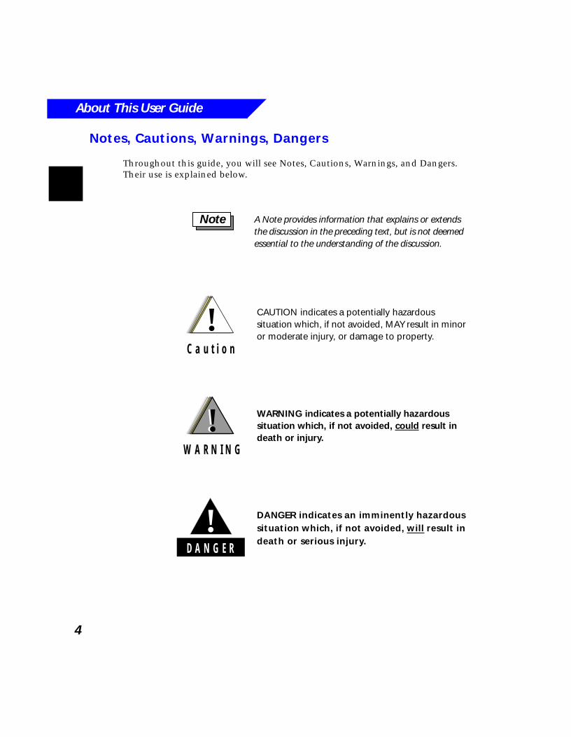
Throughout this guide, you will see Notes, Cautions, Warnings, and Dangers. Their use is explained below.
A Note provides information that explains or extends the discussion in the preceding text, but is not deemed essential to the understanding of the discussion.
Note
!C a u t i o n
CAUTION indicates a potentially hazardous situation which, if not avoided, MAY result in minor or moderate injury, or damage to property.
WARNING indicates a potentially hazardous situation which, if not avoided, could result in death or injury.
!W A R N I N G
!
DANGER indicates an imminently hazardous situation which, if not avoided, will result in death or serious injury.D A N G E R
!

5
1
MCS 2000 Overview
What’s In This Chapter?■ Product features - highlights product features and benefits (page 6)
■ Model differences - describes differences among the three radio models (page 7)
■ Mounting options - describes the three mounting options (page 8)
■ Feature programming - describes feature programming using Radio Service Software (RSS) (page 8)
■ Accessories - describes standard and optional radio accessories (page 8)
MCS 2000 Overview
6
Product Features
The MCS 2000 mobile radio family offers highly flexible radios that incorporate new features and capabilities, while providing the standard features available in previous Motorola mobile radios. In addition, as with all Motorola products, the MCS 2000 mobile family is designed to work reliably and maintain its durability under adverse conditions. The MCS 2000 family offers the following benefits:
■
Companion product to the MTS 2000 portable
The MCS 2000 mobile radio and the MTS 2000 portable radio share the same technology platform, user interface, and design. For users operating both radio types, consistency between radios means reduced training and ease of use when switching between the portable and mobile radios. Once users are familiar with one radio, they can quickly adapt to the companion product.
■
Field upgradeable and configurable
You can easily upgrade your radio in the field using the FLASHport™ feature, and can change its configuration using RSS (Radio Service Software). This permits easy migration as your radio needs grow and technology advances. New features can be added to the current system, or the radio can be reprogrammed for new system operation (within the original frequency range).
■
Wide range of frequencies
The MCS 2000 mobile radios can be ordered for the VHF, UHF, 800 MHz, or 900 MHz frequency bands.
■
Configurable for multiple trunking systems
The radio can be configured to operate on Privacy Plus, StartSite, SMARTNET, SMARTNET Type I, SmartZone, SECURENET, Automatic Multiple Site Select, MPT1327, and Select 5 systems. This provides a unique ability for your radios to be backwards compatible with other private system types, as well as offering your users the ability to operate on Specialized Mobile Radio (SMR) systems. Mobile range can be extended and back-up system operation can be facilitated with the ability to operate on SMR systems.
■
Software-configurable channel spacing
The MCS 2000 radios can be programmed to either 12.5 kHz or 25 kHz channel spacing. With 12.5 kHz channel spacing becoming a requirement in many countries, the MCS 2000 allows you to proactively meet future changes without having to purchase a new radio. The ability to program 25 kHz or 12.5 kHz channel spacing within one radio allows you to efficiently use frequency spectrum.
MCS 2000 Overview
7
Model Differences
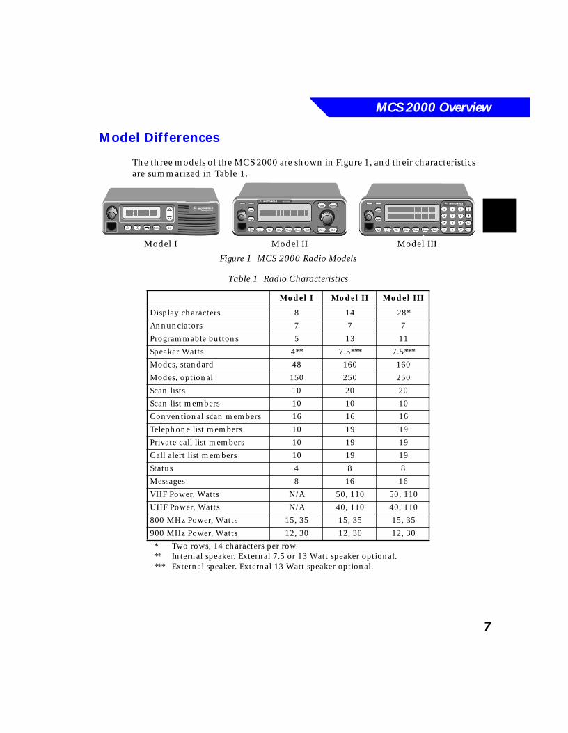
The three models of the MCS 2000 are shown in Figure 1, and their characteristics are summarized in Table 1.
Figure 1 MCS 2000 Radio Models
* Two rows, 14 characters per row.** Internal speaker. External 7.5 or 13 Watt speaker optional.*** External speaker. External 13 Watt speaker optional.
Table 1 Radio Characteristics
Model I Model II Model III
Display characters 8 14 28*
Annunciators 7 7 7
Programmable buttons 5 13 11
Speaker Watts 4** 7.5*** 7.5***
Modes, standard 48 160 160
Modes, optional 150 250 250
Scan lists 10 20 20
Scan list members 10 10 10
Conventional scan members 16 16 16
Telephone list members 10 19 19
Private call list members 10 19 19
Call alert list members 10 19 19
Status 4 8 8
Messages 8 16 16
VHF Power, Watts N/A 50, 110 50, 110
UHF Power, Watts N/A 40, 110 40, 110
800 MHz Power, Watts 15, 35 15, 35 15, 35
900 MHz Power, Watts 12, 30 12, 30 12, 30
Radiu MCS 2000
Menu SelScan Call
Zone
Page
HomeOpt
SelMenu
MCS 2000
H/L Phon
321
654
987
0
MCS 2000
H/LOpt Phon Scan Call
Sel
Menu
Zone
Page
Model I Model II Model III
MCS 2000 Overview
8
Mounting Options
The radio can be either dash-mounted or remote-mounted to permit optimal use of limited vehicle space. Remote mount cables are offered in various lengths to accommodate different vehicle sizes. Refer to Radio Installation Safety on page 91 and Airbag Warning on page 94 before installing your radio.
Feature Programming
The radio uses an electrically erasable, programmable read-only memory (EEPROM) device to store software and configuration information. The radio can be programmed in the field using an IBM-compatible personal computer equipped with the appropriate Motorola Radio Service Software (RSS).
Accessories
Standard Accessories
The MCS 2000 offers a complete range of radio accessories to meet your needs. In an effort to minimize customer costs, the MCS 2000 is backwards compatible with many existing mobile accessories.
The standard accessories shipped with your MCS 2000 radio are:
■ Microphone
■ Speaker (Models II and III only; Model I has a built-in speaker)
■ Trunnion mounting bracket
■ Power cable
■ Quick start user guide
The high-power (110 Watt) radio must be remote mounted.
Note
MCS 2000 Overview
9
Microphone Accessories■ Second microphone option. An additional microphone can be connected to
the accessory connector. A microphone adapter cable and a second microphone are required.
■ Hands-free operation. The radio can be operated hands-free by using a visor microphone and PTT footswitch. The visor microphone is also used for the Emergency With Voice to Follow feature. See page 65 for more information.
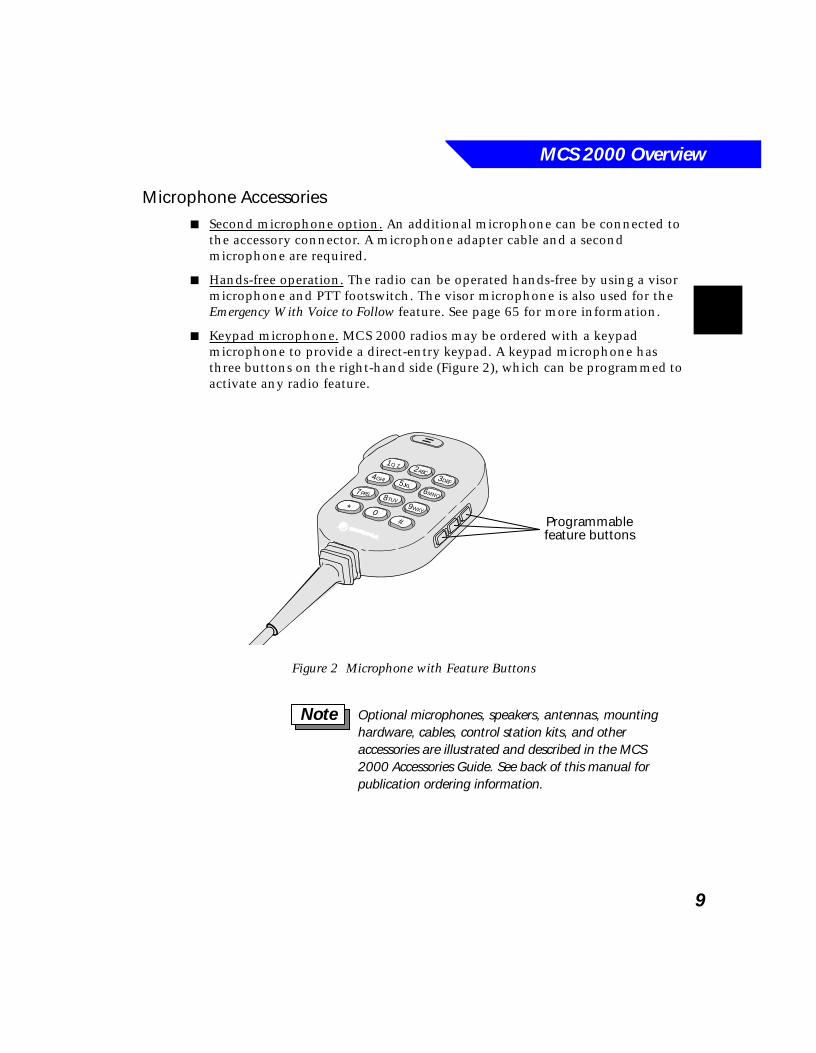
■ Keypad microphone. MCS 2000 radios may be ordered with a keypad microphone to provide a direct-entry keypad. A keypad microphone has three buttons on the right-hand side (Figure 2), which can be programmed to activate any radio feature.
Figure 2 Microphone with Feature Buttons
2ABC3DEF
4GHI
6MNO7PRS 8TUV
9WXY0*#
1Q Z
5JKL
Programmablefeature buttons
Optional microphones, speakers, antennas, mounting hardware, cables, control station kits, and other accessories are illustrated and described in the MCS 2000 Accessories Guide. See back of this manual for publication ordering information.
Note
MCS 2000 Overview
10
Accessory Connector
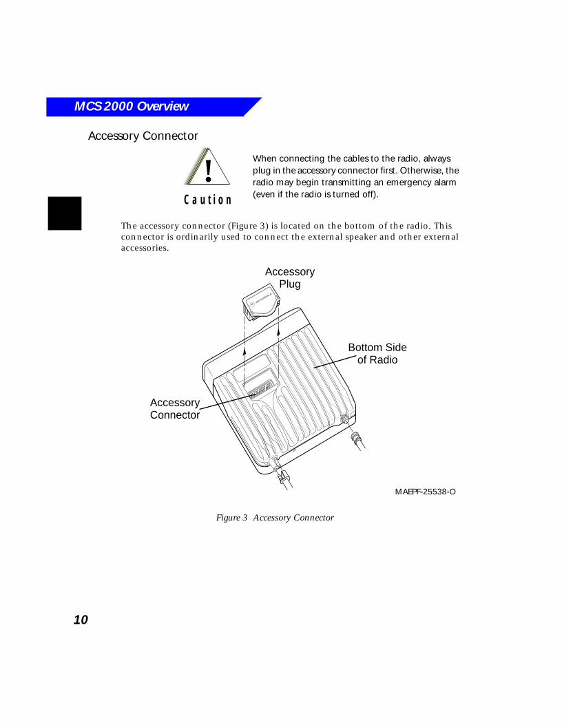
The accessory connector (Figure 3) is located on the bottom of the radio. This connector is ordinarily used to connect the external speaker and other external accessories.
Figure 3 Accessory Connector
!C a u t i o n
When connecting the cables to the radio, always plug in the accessory connector first. Otherwise, the radio may begin transmitting an emergency alarm (even if the radio is turned off).
AccessoryConnector
Bottom Sideof Radio
ControlHead
RadioChassis
PowerCable
AntennaCable
MicrophoneCord
AccessoryPlug
MAEPF-25538-O
11
2Radio Controls
What’s In This Chapter?■ MCS 2000 controls - shows and describes Model I, II, and III controls
(page 12)
■ Control buttons - lists and describes the radio’s control buttons, which are common across all three models (page 14)
■ Display - shows and describes the Model I, II, and III display (page 16)
■ Display annunciators - lists and describes the annunciators (icons) appearing in the display (page 17)
Radio Controls
12
MCS 2000 Controls
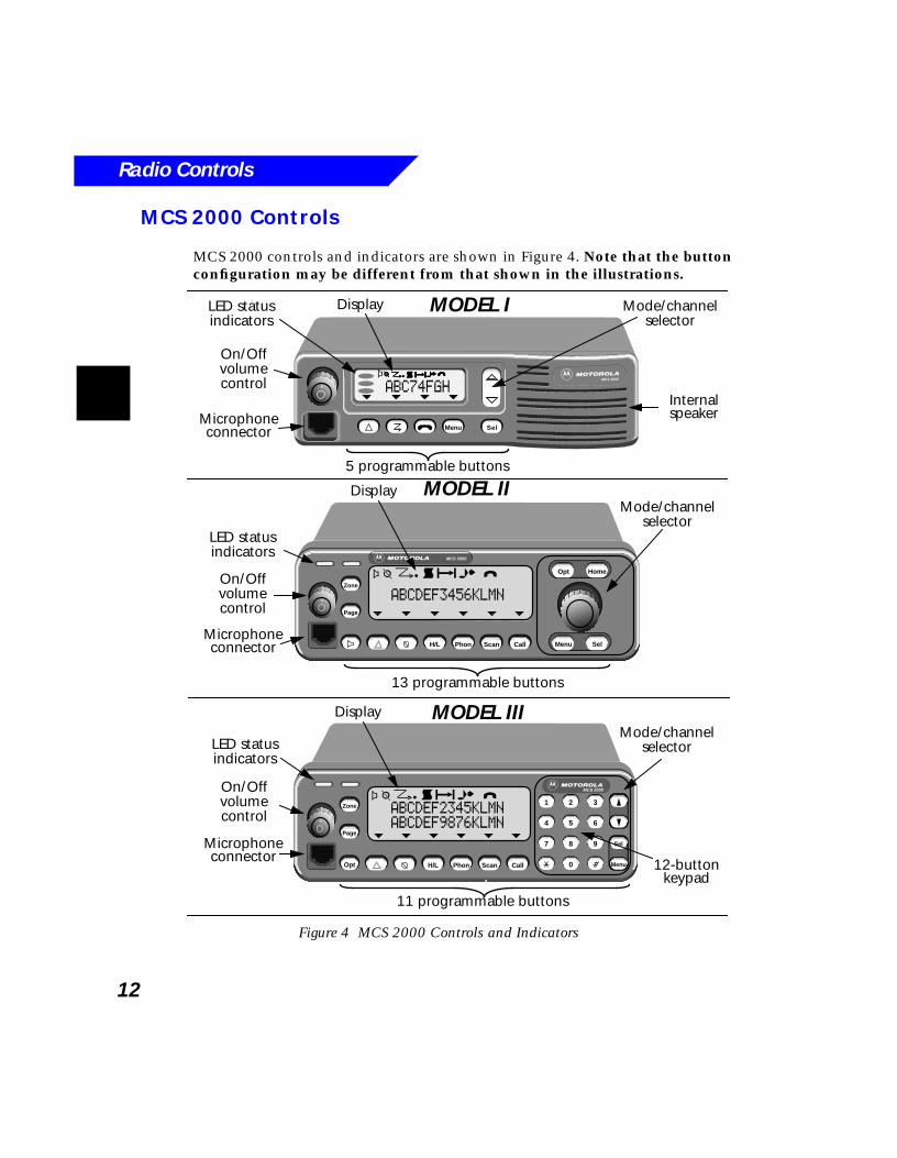
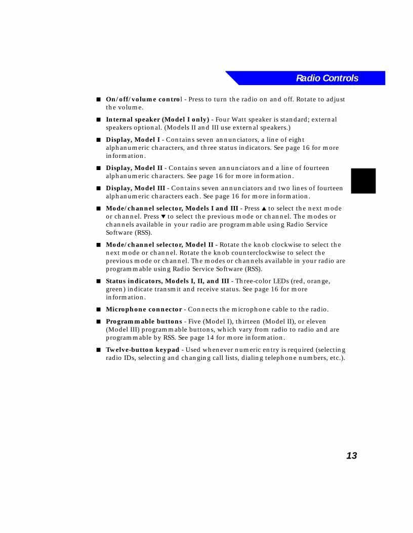
MCS 2000 controls and indicators are shown in Figure 4. Note that the button configuration may be different from that shown in the illustrations.
Figure 4 MCS 2000 Controls and Indicators
MCS 2000
Menu Sel
5 programmable buttons
Microphoneconnector
Internalspeaker
On/Offvolumecontrol
LED statusindicators
ABC74FGH
Mode/channelselector
Scan Call
Zone
Page
HomeOpt
SelMenu
MCS 2000
H/L Phon
Mode/channelselector
On/Offvolumecontrol
LED statusindicators
Microphoneconnector
13 programmable buttons
MODEL I
MODEL II
321
654
987
0
MCS 2000
H/LOpt Phon Scan Call
Sel
Menu
Zone
Page
Microphoneconnector
On/Offvolumecontrol
LED statusindicators
11 programmable buttons
12-buttonkeypad
Mode/channelselector
MODEL III
ABCDEF3456KLMN
a bbbbccccddddjjjjeeeeiiii
Display
ABCDEF2345KLMNABCDEF9876KLMN
Display
Display
a bc djei
a bc djei
Radio Controls
13
■ On/off/volume control - Press to turn the radio on and off. Rotate to adjust the volume.
■ Internal speaker (Model I only) - Four Watt speaker is standard; external speakers optional. (Models II and III use external speakers.)
■ Display, Model I - Contains seven annunciators, a line of eight alphanumeric characters, and three status indicators. See page 16 for more information.
■ Display, Model II - Contains seven annunciators and a line of fourteen alphanumeric characters. See page 16 for more information.
■ Display, Model III - Contains seven annunciators and two lines of fourteen alphanumeric characters each. See page 16 for more information.
■ Mode/channel selector, Models I and III - Press ▲ to select the next mode or channel. Press ▼ to select the previous mode or channel. The modes or channels available in your radio are programmable using Radio Service Software (RSS).
■ Mode/channel selector, Model II - Rotate the knob clockwise to select the next mode or channel. Rotate the knob counterclockwise to select the previous mode or channel. The modes or channels available in your radio are programmable using Radio Service Software (RSS).
■ Status indicators, Models I, II, and III - Three-color LEDs (red, orange, green) indicate transmit and receive status. See page 16 for more information.
■ Microphone connector - Connects the microphone cable to the radio.
■ Programmable buttons - Five (Model I), thirteen (Model II), or eleven (Model III) programmable buttons, which vary from radio to radio and are programmable by RSS. See page 14 for more information.
■ Twelve-button keypad - Used whenever numeric entry is required (selecting radio IDs, selecting and changing call lists, dialing telephone numbers, etc.).
Radio Controls
14
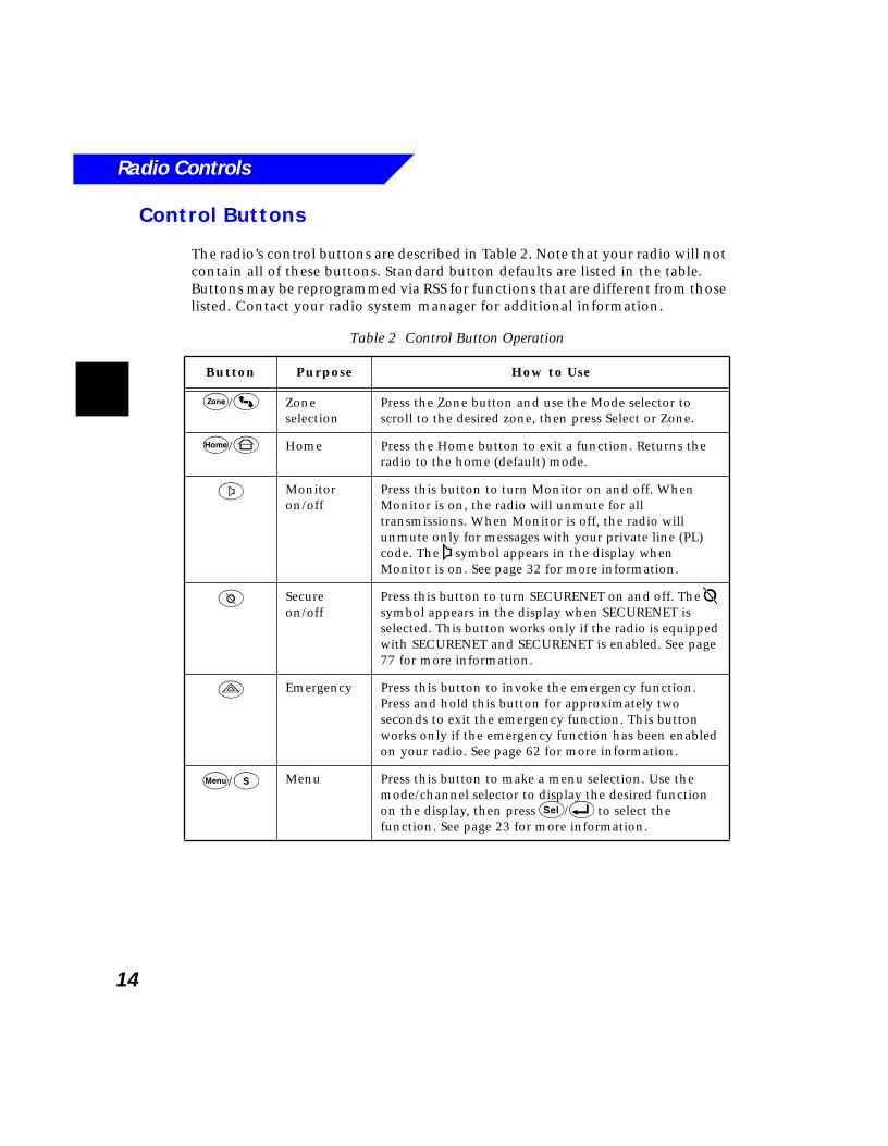
Control Buttons
The radio’s control buttons are described in Table 2. Note that your radio will not contain all of these buttons. Standard button defaults are listed in the table. Buttons may be reprogrammed via RSS for functions that are different from those listed. Contact your radio system manager for additional information.
Table 2 Control Button Operation
Button Purpose How to Use
Z/4 Zone selection
Press the Zone button and use the Mode selector to scroll to the desired zone, then press Select or Zone.
h/6 Home Press the Home button to exit a function. Returns the radio to the home (default) mode.
2 Monitoron/off
Press this button to turn Monitor on and off. When Monitor is on, the radio will unmute for all transmissions. When Monitor is off, the radio will unmute only for messages with your private line (PL) code. The a symbol appears in the display when Monitor is on. See page 32 for more information.
3 Secureon/off
Press this button to turn SECURENET on and off. The b symbol appears in the display when SECURENET is selected. This button works only if the radio is equipped with SECURENET and SECURENET is enabled. See page 77 for more information.
1 Emergency Press this button to invoke the emergency function. Press and hold this button for approximately two seconds to exit the emergency function. This button works only if the emergency function has been enabled on your radio. See page 62 for more information.
M/t Menu Press this button to make a menu selection. Use the mode/channel selector to display the desired function on the display, then press s/8 to select the function. See page 23 for more information.
Radio Controls
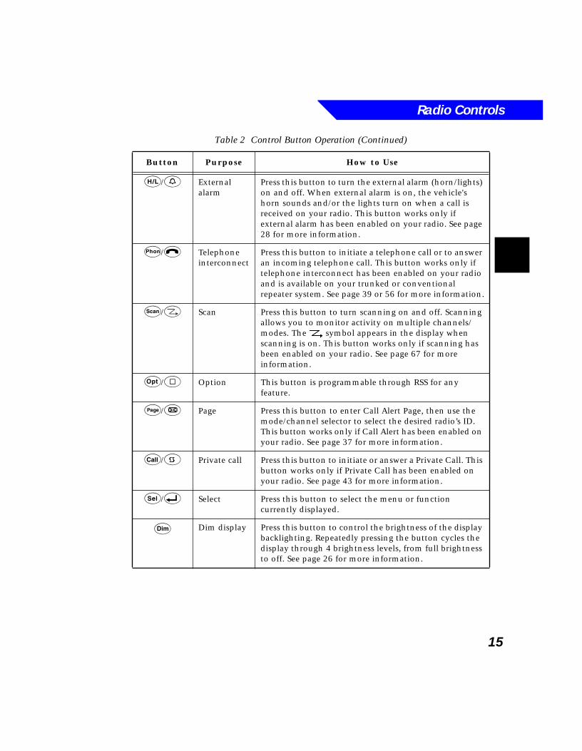
15
H/0 External alarm
Press this button to turn the external alarm (horn/lights) on and off. When external alarm is on, the vehicle's horn sounds and/or the lights turn on when a call is received on your radio. This button works only if external alarm has been enabled on your radio. See page 28 for more information.
p/$ Telephone interconnect
Press this button to initiate a telephone call or to answer an incoming telephone call. This button works only if telephone interconnect has been enabled on your radio and is available on your trunked or conventional repeater system. See page 39 or 56 for more information.
S/: Scan Press this button to turn scanning on and off. Scanning allows you to monitor activity on multiple channels/modes. The symbol appears in the display when scanning is on. This button works only if scanning has been enabled on your radio. See page 67 for more information.
O/7 Option This button is programmable through RSS for any feature.
P/& Page Press this button to enter Call Alert Page, then use the mode/channel selector to select the desired radio’s ID. This button works only if Call Alert has been enabled on your radio. See page 37 for more information.
C/9 Private call Press this button to initiate or answer a Private Call. This button works only if Private Call has been enabled on your radio. See page 43 for more information.
s/8 Select Press this button to select the menu or function currently displayed.
D Dim display Press this button to control the brightness of the display backlighting. Repeatedly pressing the button cycles the display through 4 brightness levels, from full brightness to off. See page 26 for more information.
Table 2 Control Button Operation (Continued)
Button Purpose How to Use
Radio Controls
16
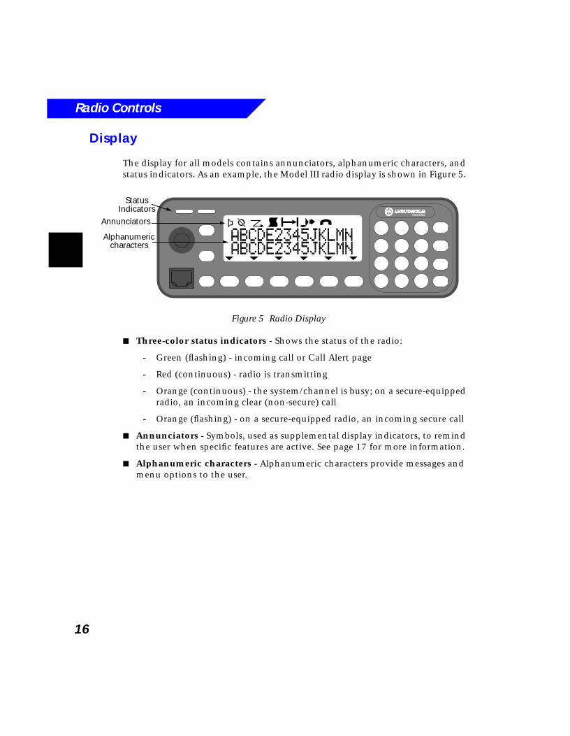
Display
The display for all models contains annunciators, alphanumeric characters, and status indicators. As an example, the Model III radio display is shown in Figure 5.
Figure 5 Radio Display
■ Three-color status indicators - Shows the status of the radio:
- Green (flashing) - incoming call or Call Alert page
- Red (continuous) - radio is transmitting
- Orange (continuous) - the system/channel is busy; on a secure-equipped radio, an incoming clear (non-secure) call
- Orange (flashing) - on a secure-equipped radio, an incoming secure call
■ Annunciators - Symbols, used as supplemental display indicators, to remind the user when specific features are active. See page 17 for more information.
■ Alphanumeric characters - Alphanumeric characters provide messages and menu options to the user.
MCS 2000
a b djei
ABCDE2345JKLMNABCDE2345JKLMN
StatusIndicators
Annunciators
Alphanumericcharacters
Radio Controls
17
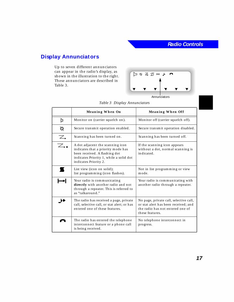
Display Annunciators
Up to seven different annunciators can appear in the radio’s display, as shown in the illustration to the right. These annunciators are described in Table 3.
Table 3 Display Annunciators
Meaning When On Meaning When Off
a Monitor on (carrier squelch on). Monitor off (carrier squelch off).
b Secure transmit operation enabled. Secure transmit operation disabled.
Scanning has been turned on. Scanning has been turned off.
A dot adjacent the scanning icon indicates that a priority mode has been received. A flashing dot indicates Priority 1, while a solid dot indicates Priority 2.
If the scanning icon appears without a dot, normal scanning is indicated.
d List view (icon on solid);list programming (icon flashes).
Not in list programming or view mode.
j Your radio is communicating directly with another radio and not through a repeater. This is referred to as “talkaround.”
Your radio is communicating with another radio through a repeater.
e The radio has received a page, private call, selective call, or stat alert; or has entered one of these features.
No page, private call, selective call, or stat alert has been received; and the radio has not entered one of these features.
i The radio has entered the telephone interconnect feature or a phone call is being received.
No telephone interconnect in progress.
Annunciators
i

Radio Controls
18
19
3Basic Radio Operation
What’s In This Chapter?■ Turning the radio on and off - describes how to turn the radio on and
off, and also covers the optional ignition sense function (page 20)
■ Setting receiver volume - describes how to set the receiver’s volume level (page 21)
■ Selecting radio features - describes how to select the radio’s features using either buttons or the menu (page 22)
■ Zone/Channel Assignment - describes the relationship between zones and channels and describes how to select zones and channels; also covers the rotary alert feature (page 24)
■ Selecting the home mode - describes how to return to the home mode from any other mode (page 26)
■ Adjusting display brightness - describes how to adjust the display’s brightness and how to turn the backlight off (page 26)
■ Setting transmitter power level - describes how to select either high or low power transmitter operation (page 27)
■ External alarm - describes how to enable the optional external alarm feature, which notifies you of incoming calls when you are out of your vehicle (page 28)
■ Using the time-out timer - describes the time-out timer, which prevents locking up a repeater or channel by prolonged keying of the radio's transmitter (page 29)
■ Alert tones - describes the tones emitted from the radio to alert the operator of certain functions; includes a graphic table (page 29)
Basic Radio Operation
20
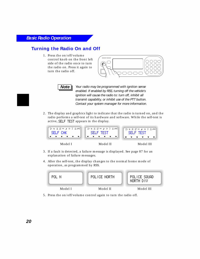
Turning the Radio On and Off1. Press the on/off/volume
control knob on the front left side of the radio once to turn the radio on. Press it again to turn the radio off.
2. The display and graphics light to indicate that the radio is turned on, and the radio performs a self-test of its hardware and software. While the self-test is active, SELF TEST appears in the display.
3. If a fault is detected, a failure message is displayed. See page 87 for an explanation of failure messages.
4. After the self-test, the display changes to the normal home mode of operation, as programmed by RSS.
5. Press the on/off/volume control again to turn the radio off.
Your radio may be programmed with ignition sense enabled. If enabled by RSS, turning off the vehicle’s ignition will cause the radio to: turn off, inhibit all transmit capability, or inhibit use of the PTT button.Contact your system manager for more information.
Note
Model I Model II Model III
SELF TESTSELF CHK SELF TEST
Model I Model II Model III
POLICE SQUAD
NORTH DIV
POLICE NORTHPOL N
Basic Radio Operation
21
Test Mode
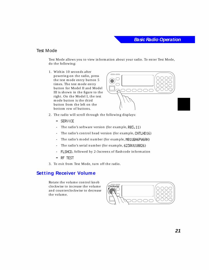
Test Mode allows you to view information about your radio. To enter Test Mode, do the following:
1. Within 10 seconds after powering-on the radio, press the test mode entry button 5 times. The test mode entry button for Model II and Model III is shown in the figure to the right. On the Model I, the test mode button is the third button from the left on the bottom row of buttons.
2. The radio will scroll through the following displays:
---- SERVICE
- The radio’s software version (for example, R03.11)
- The radio’s control head version (for example, CNTLHD16)
- The radio’s model number (for example, M01UGN6PW6AN)
- The radio’s serial number (for example, 623AVU10026)
- FLSHCD, followed by 2-3screens of flashcode information
---- RF TEST
3. To exit from Test Mode, turn off the radio.
Setting Receiver Volume
Rotate the volume control knob clockwise to increase the volume and counterclockwise to decrease the volume.
Clockwise
Basic Radio Operation
22
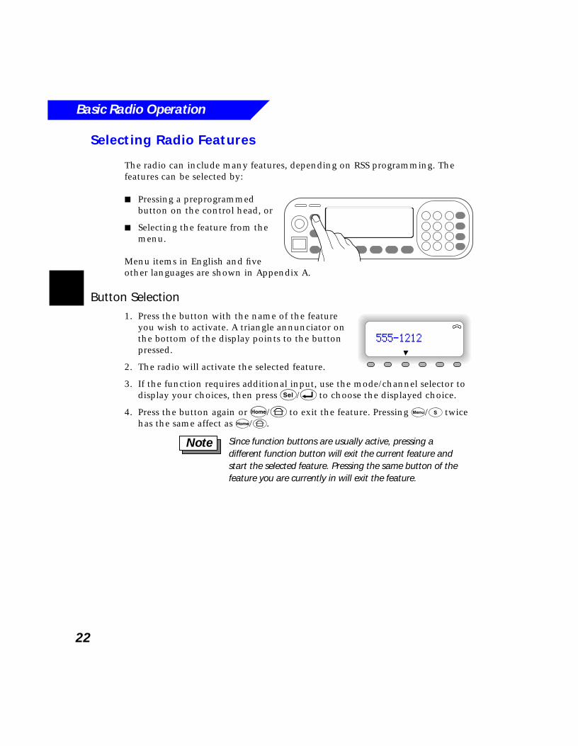
Selecting Radio Features
The radio can include many features, depending on RSS programming. The features can be selected by:
■ Pressing a preprogrammed button on the control head, or
■ Selecting the feature from the menu.
Menu items in English and five other languages are shown in Appendix A.
Button Selection1. Press the button with the name of the feature
you wish to activate. A triangle annunciator on the bottom of the display points to the button pressed.
2. The radio will activate the selected feature.
3. If the function requires additional input, use the mode/channel selector to display your choices, then press s/8 to choose the displayed choice.
4. Press the button again or h/6 to exit the feature. Pressing M/t twice has the same affect as h/6.
555-1212
Since function buttons are usually active, pressing a different function button will exit the current feature and start the selected feature. Pressing the same button of the feature you are currently in will exit the feature.
Note
Basic Radio Operation
23
Menu Selection
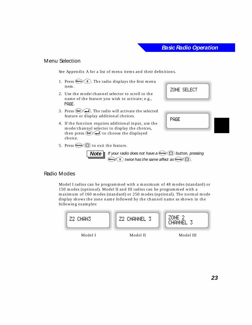
See Appendix A for a list of menu items and their definitions.
1. Press M/t. The radio displays the first menu item.
2. Use the mode/channel selector to scroll to the name of the feature you wish to activate; e.g., PAGE.
3. Press s/8. The radio will activate the selected feature or display additional choices.
4. If the function requires additional input, use the mode/channel selector to display the choices, then press s/8 to choose the displayed choice.
5. Press h/6 to exit the feature.
Radio Modes
Model I radios can be programmed with a maximum of 48 modes (standard) or 150 modes (optional). Model II and III radios can be programmed with a maximum of 160 modes (standard) or 250 modes (optional). The normal mode display shows the zone name followed by the channel name as shown in the following examples:
ZONE SELECT
PAGE
If your radio does not have a h/6 button, pressing
M/t twice has the same affect as h/6.Note
Model I Model II Model III
Z2 CHAN3 Z2 CHANNEL 3 ZONE 2CHANNEL 3
Basic Radio Operation
24
Zone/Channel Assignment
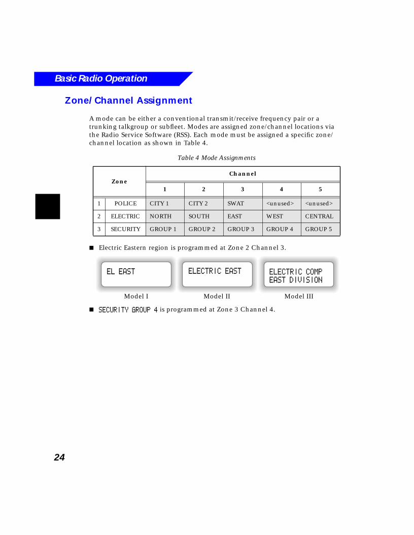
A mode can be either a conventional transmit/receive frequency pair or a trunking talkgroup or subfleet. Modes are assigned zone/channel locations via the Radio Service Software (RSS). Each mode must be assigned a specific zone/channel location as shown in Table 4.
■ Electric Eastern region is programmed at Zone 2 Channel 3.
■ SECURITY GROUP 4 is programmed at Zone 3 Channel 4.
Table 4 Mode Assignments
ZoneChannel
1 2 3 4 5
1 POLICE CITY 1 CITY 2 SWAT <unused> <unused>
2 ELECTRIC NORTH SOUTH EAST WEST CENTRAL
3 SECURITY GROUP 1 GROUP 2 GROUP 3 GROUP 4 GROUP 5
Model I Model II Model III
ELECTRIC COMP
EAST DIVISION
ELECTRIC EASTEL EAST
Basic Radio Operation
25
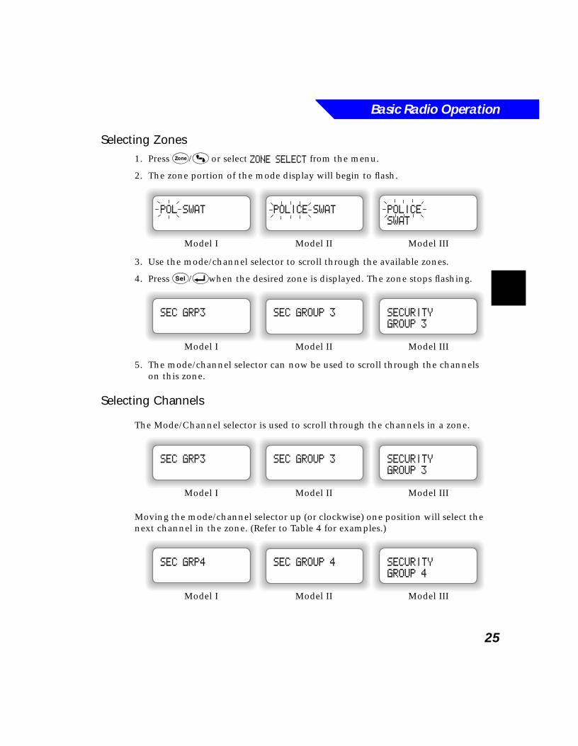
Selecting Zones1. Press Z/4 or select ZONE SELECT from the menu.
2. The zone portion of the mode display will begin to flash.
3. Use the mode/channel selector to scroll through the available zones.
4. Press s/8when the desired zone is displayed. The zone stops flashing.
5. The mode/channel selector can now be used to scroll through the channels on this zone.
Selecting Channels
The Mode/Channel selector is used to scroll through the channels in a zone.
Moving the mode/channel selector up (or clockwise) one position will select the next channel in the zone. (Refer to Table 4 for examples.)
Model I Model II Model III
POLICE
SWAT
POLICE SWATPOL SWAT
Model I Model II Model III
SECURITY
GROUP 3
SEC GROUP 3SEC GRP3
Model I Model II Model III
SECURITY
GROUP 3
SEC GROUP 3SEC GRP3
Model I Model II Model III
SECURITY
GROUP 4
SEC GROUP 4SEC GRP4
Basic Radio Operation
26
Rotary Selector
Channels are selected on the Model II radio by turning the rotary selector clockwise or counterclockwise. The knob can be programmed by RSS to do one of the following:
■ Rollover: Wrap around from the last channel to the first channel when turning clockwise or from the first channel to the last channel when turning counterclockwise.
■ Rollover Alert: Generate an audible alert tone when wrapping around from the last channel to the first channel when turning clockwise or from the first channel to the last channel when turning counterclockwise.
■ Electronic Stop: Stop at the last channel when turning clockwise or stop at the first channel when turning counterclockwise.
Selecting the Home Mode
Press h/6 (if so equipped) to select the home mode from any other mode in the radio, regardless of which zone is currently selected. The home mode is enabled or disabled by the RSS.
Adjusting Display Brightness
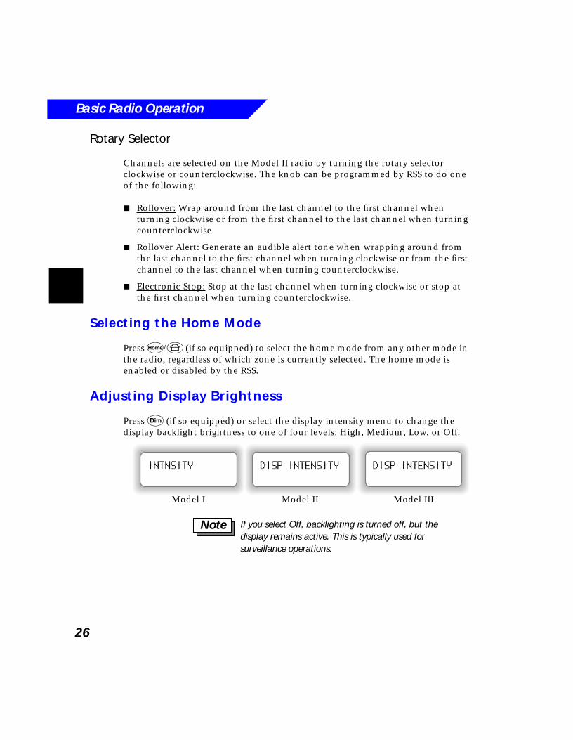
Press D (if so equipped) or select the display intensity menu to change the display backlight brightness to one of four levels: High, Medium, Low, or Off.
Model I Model II Model III
DISP INTENSITYDISP INTENSITYINTNSITY
If you select Off, backlighting is turned off, but the display remains active. This is typically used for surveillance operations.
Note
Basic Radio Operation
27
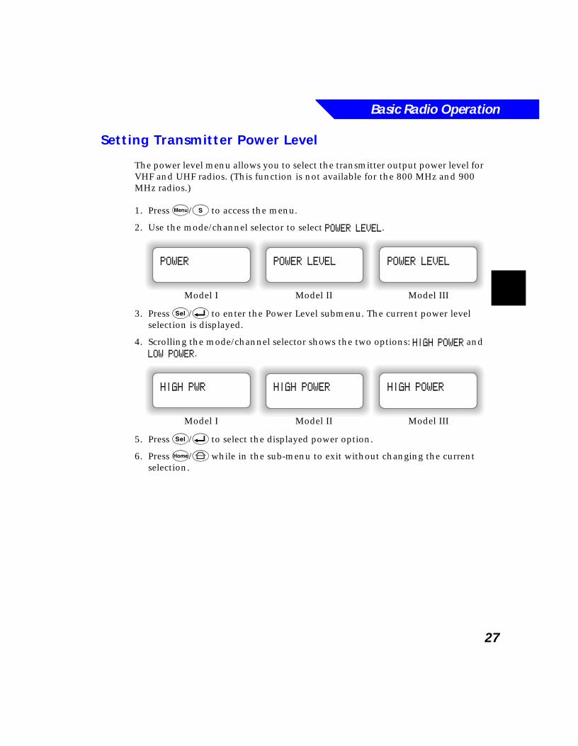
Setting Transmitter Power Level
The power level menu allows you to select the transmitter output power level for VHF and UHF radios. (This function is not available for the 800 MHz and 900 MHz radios.)
1. Press M/t to access the menu.
2. Use the mode/channel selector to select POWER LEVEL.
3. Press s/8 to enter the Power Level submenu. The current power level selection is displayed.
4. Scrolling the mode/channel selector shows the two options: HIGH POWER and LOW POWER.
5. Press s/8 to select the displayed power option.
6. Press h/6 while in the sub-menu to exit without changing the current selection.
Model I Model II Model III
POWER LEVELPOWER LEVELPOWER
Model I Model II Model III
HIGH POWERHIGH POWERHIGH PWR
Basic Radio Operation
28
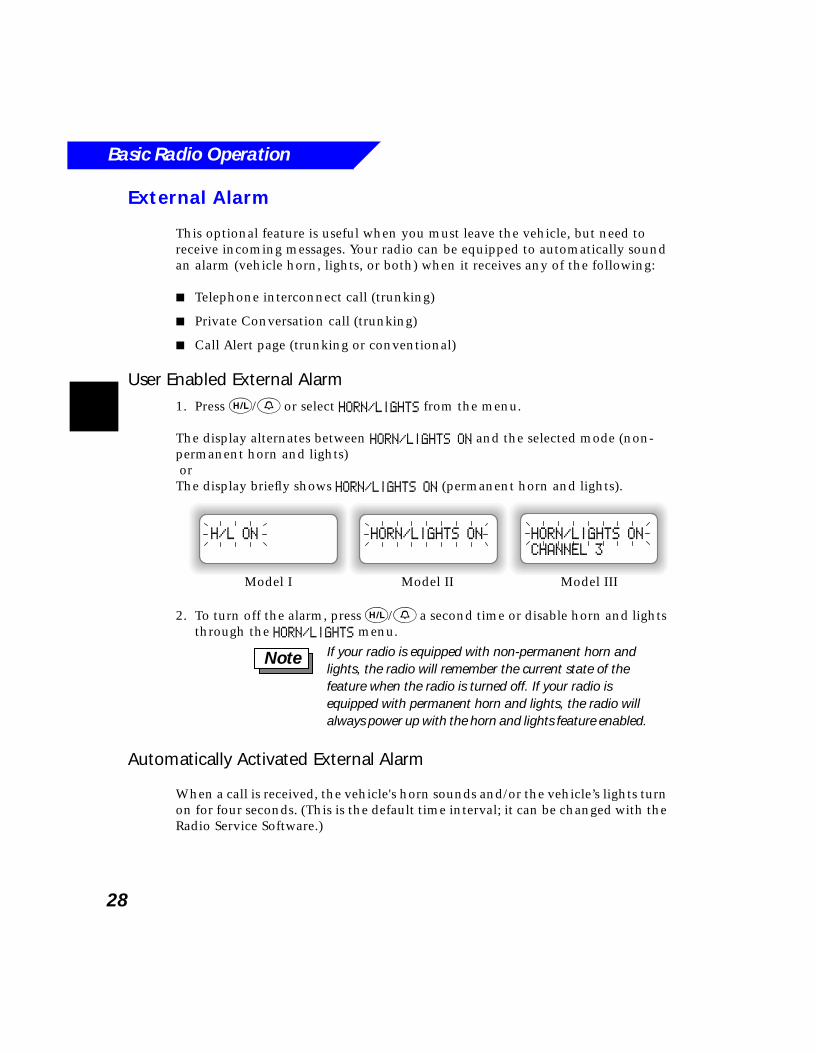
External Alarm
This optional feature is useful when you must leave the vehicle, but need to receive incoming messages. Your radio can be equipped to automatically sound an alarm (vehicle horn, lights, or both) when it receives any of the following:
■ Telephone interconnect call (trunking)
■ Private Conversation call (trunking)
■ Call Alert page (trunking or conventional)
User Enabled External Alarm1. Press H/0 or select HORN/LIGHTS from the menu.
The display alternates between HORN/LIGHTS ON and the selected mode (non-permanent horn and lights) orThe display briefly shows HORN/LIGHTS ON (permanent horn and lights).
2. To turn off the alarm, press H/0 a second time or disable horn and lights through the HORN/LIGHTS menu.
Automatically Activated External Alarm
When a call is received, the vehicle's horn sounds and/or the vehicle’s lights turn on for four seconds. (This is the default time interval; it can be changed with the Radio Service Software.)
Model I Model II Model III
HORN/LIGHTS ON
CHANNEL 3
HORN/LIGHTS ONH/L ON
If your radio is equipped with non-permanent horn and lights, the radio will remember the current state of the feature when the radio is turned off. If your radio is equipped with permanent horn and lights, the radio will always power up with the horn and lights feature enabled.
Note
Basic Radio Operation
29
Two external alarm options are available:
■ Non-rearmable alarm (the external alarm shuts off after acknowledge):
1. To acknowledge and turn off the external alarm, press the PTT or any control head button except D.
2. The external alarm automatically turns off, and the feature is exited.
3. To re-activate the feature, press H/0 or select HORN/LIGHTS from the menu; the alarm will then be re-armed.
■ Rearmable alarm (the external alarm is automatically re-armed after acknowledge):
1. To acknowledge and turn off the external alarm, press the PTT or any control head button except D.
2. When the external alarm is acknowledged, it is automatically re-armed.
Using the Time-out TimerYour radio provides a Time-out Timer function to prevent locking up a repeater or channel by prolonged keying of the radio's transmitter. You may not transmit longer than the preset timer setting. If you attempt to do so, the radio stops your transmission automatically, and you will hear a talk-prohibit tone.
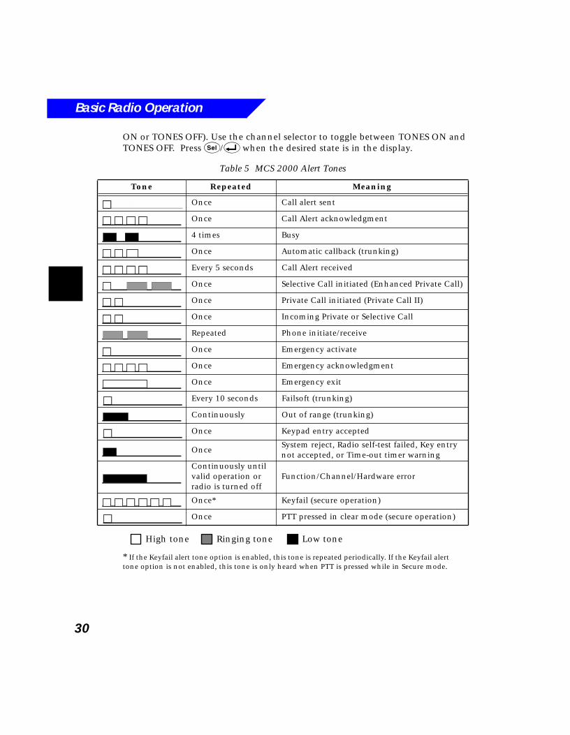
Alert Tones
Alert tones for the MCS 2000 are listed in Table 5. Note the definitions of tones at the end of the table.
Keypad Tone Muting
The tones heard whenever a key is pressed my be turned on or off by selecting TONES from the menu. The current status of keypad tones is displayed (TONES
Re-armable alarm only: Pressing H/0 will turn off the external alarm and exit the horn and lights feature. The horn and lights feature can be re-activated by pressing H/0 to re-arm the alarm.
Note
You will hear a low-pitched, brief warning tone four seconds before the transmission times out.
Note
Basic Radio Operation
30
ON or TONES OFF). Use the channel selector to toggle between TONES ON and TONES OFF. Press s/8 when the desired state is in the display.
* If the Keyfail alert tone option is enabled, this tone is repeated periodically. If the Keyfail alert tone option is not enabled, this tone is only heard when PTT is pressed while in Secure mode.
Table 5 MCS 2000 Alert Tones
Tone Repeated Meaning
Once Call alert sent
Once Call Alert acknowledgment
4 times Busy
Once Automatic callback (trunking)
Every 5 seconds Call Alert received
Once Selective Call initiated (Enhanced Private Call)
Once Private Call initiated (Private Call II)
Once Incoming Private or Selective Call
Repeated Phone initiate/receive
Once Emergency activate
Once Emergency acknowledgment
Once Emergency exit
Every 10 seconds Failsoft (trunking)
Continuously Out of range (trunking)
Once Keypad entry accepted
OnceSystem reject, Radio self-test failed, Key entry not accepted, or Time-out timer warning
Continuously until valid operation or radio is turned off
Function/Channel/Hardware error
Once* Keyfail (secure operation)
Once PTT pressed in clear mode (secure operation)
High tone Ringing tone Low tone
31
4Conventional Operation
What’s In This Chapter?■ Monitor - describes how to unmute the radio’s squelch control to
monitor voice traffic on a channel (page 32)
■ Transmitting - describes how to transmit on a selected channel and how to use the Smart Push-to-Talk, Quick-Key Override, and Private Line Code features (page 32)
■ Talkaround - describes how to bypass the repeater and talk directly with other radios (page 34)
■ Selective Call - describes how to receive and respond to a Selective Call (page 35)
■ Call Alert Page - describes how to page another radio (page 37)
■ Quick call II - describes how to set the radio to decode calls (page 38)
■ GE Star - describes the automatic identification system and emergency alarm without acknowledgment (page 38)
■ Singletone Repeater Access - describes a method of choosing a specific repeater to use (page 39)
■ Telephone Interconnect - describes how to use the telephone feature on a conventional system (page 39)
Conventional Operation
32
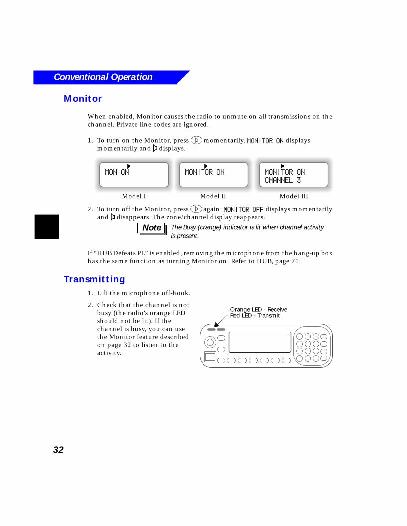
Monitor
When enabled, Monitor causes the radio to unmute on all transmissions on the channel. Private line codes are ignored.
1. To turn on the Monitor, press 2 momentarily. MONITOR ON displays momentarily and a displays.
2. To turn off the Monitor, press 2 again. MONITOR OFF displays momentarily and a disappears. The zone/channel display reappears.
If “HUB Defeats PL” is enabled, removing the microphone from the hang-up box has the same function as turning Monitor on. Refer to HUB, page 71.
Transmitting1. Lift the microphone off-hook.
2. Check that the channel is not busy (the radio's orange LED should not be lit). If the channel is busy, you can use the Monitor feature described on page 32 to listen to the activity.
Model I Model II Model III
MONITOR ON
CHANNEL 3
MONITOR ONMON ON
The Busy (orange) indicator is lit when channel activity is present.
Note
Orange LED - ReceiveRed LED - Transmit
Conventional Operation
33
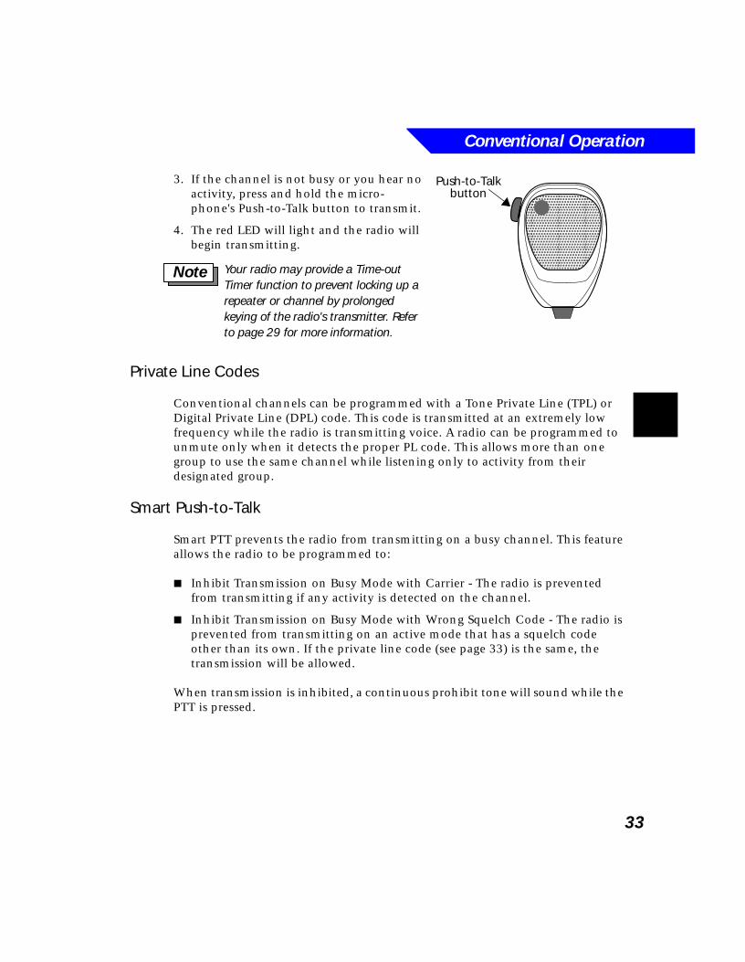
3. If the channel is not busy or you hear no activity, press and hold the micro-phone's Push-to-Talk button to transmit.
4. The red LED will light and the radio will begin transmitting.
Private Line Codes
Conventional channels can be programmed with a Tone Private Line (TPL) or Digital Private Line (DPL) code. This code is transmitted at an extremely low frequency while the radio is transmitting voice. A radio can be programmed to unmute only when it detects the proper PL code. This allows more than one group to use the same channel while listening only to activity from their designated group.
Smart Push-to-Talk
Smart PTT prevents the radio from transmitting on a busy channel. This feature allows the radio to be programmed to:
■ Inhibit Transmission on Busy Mode with Carrier - The radio is prevented from transmitting if any activity is detected on the channel.
■ Inhibit Transmission on Busy Mode with Wrong Squelch Code - The radio is prevented from transmitting on an active mode that has a squelch code other than its own. If the private line code (see page 33) is the same, the transmission will be allowed.
When transmission is inhibited, a continuous prohibit tone will sound while the PTT is pressed.
����������������������������
Push-to-Talkbutton
Your radio may provide a Time-out Timer function to prevent locking up a repeater or channel by prolonged keying of the radio's transmitter. Refer to page 29 for more information.
Note
Conventional Operation
34
Quick-Key Override
Quick-Key Override can be used in conjunction with either of the two Smart PTT variations. With this feature enabled, you can override the transmit-inhibit state by quick-keying the radio (de-keying and re-keying the PTT within one second).
Talkaround
This feature allows you to bypass the repeater and talk directly with other radios using the same transmit and receive frequencies. This is useful when radios are within close proximity to each other, or are outside the range of the repeater system.
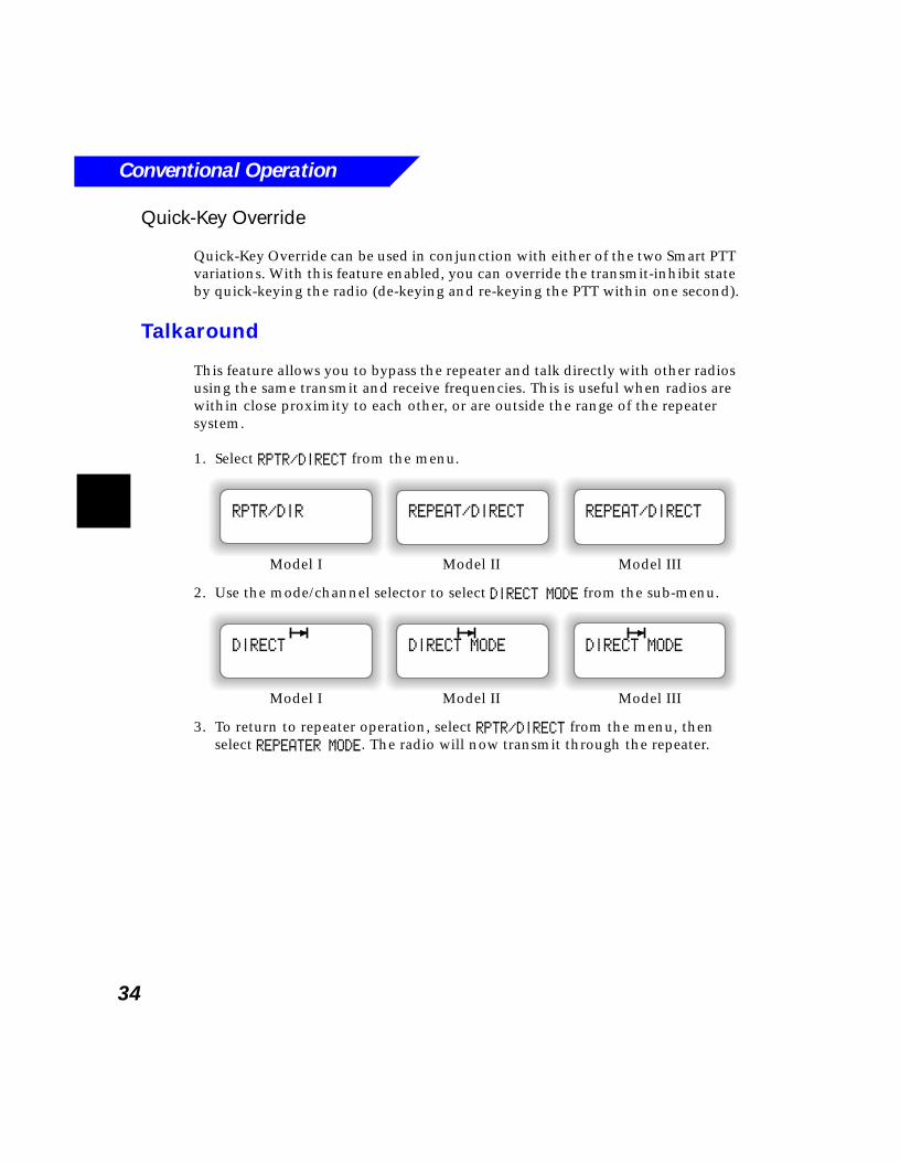
1. Select RPTR/DIRECT from the menu.
2. Use the mode/channel selector to select DIRECT MODE from the sub-menu.
3. To return to repeater operation, select RPTR/DIRECT from the menu, then select REPEATER MODE. The radio will now transmit through the repeater.
Model I Model II Model III
REPEAT/DIRECTREPEAT/DIRECTRPTR/DIR
Model I Model II Model III
DIRECT MODEDIRECT MODEDIRECT
Conventional Operation
35
Selective Call
Selective Call is a special method of unmuting a radio by means other than PL codes. Radios may be programmed to unmute on receiving proper PL code or a Selective Call (OR muting option), or they may need to receive both PL code and Selective Call to unmute (AND muting option).
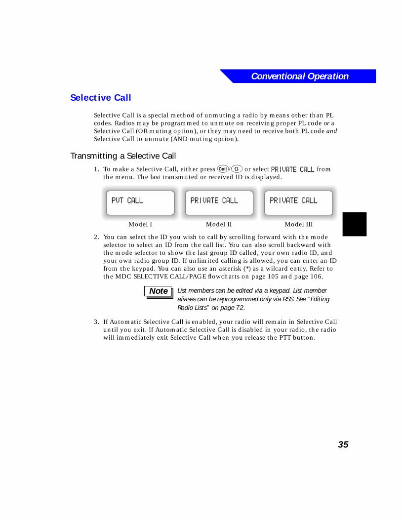
Transmitting a Selective Call1. To make a Selective Call, either press C/9 or select PRIVATE CALL from
the menu. The last transmitted or received ID is displayed.
2. You can select the ID you wish to call by scrolling forward with the mode selector to select an ID from the call list. You can also scroll backward with the mode selector to show the last group ID called, your own radio ID, and your own radio group ID. If unlimited calling is allowed, you can enter an ID from the keypad. You can also use an asterisk (*) as a wilcard entry. Refer to the MDC SELECTIVE CALL/PAGE flowcharts on page 105 and page 106.
3. If Automatic Selective Call is enabled, your radio will remain in Selective Call until you exit. If Automatic Selective Call is disabled in your radio, the radio will immediately exit Selective Call when you release the PTT button.
Model I Model II Model III
PRIVATE CALLPRIVATE CALLPVT CALL
List members can be edited via a keypad. List member aliases can be reprogrammed only via RSS. See “Editing Radio Lists” on page 72.
Note
Conventional Operation
36
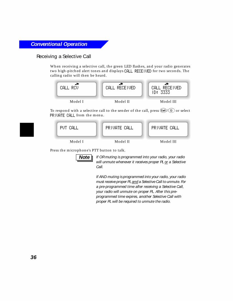
Receiving a Selective Call
When receiving a selective call, the green LED flashes, and your radio generates two high-pitched alert tones and displays CALL RECEIVED for two seconds. The calling radio will then be heard.
To respond with a selective call to the sender of the call, press C/9 or select PRIVATE CALL from the menu.
Press the microphone's PTT button to talk.
Model I Model II Model III
CALL RECEIVED
ID: 3333
CALL RECEIVEDCALL RCV
Model I Model II Model III
PRIVATE CALLPRIVATE CALLPVT CALL
If OR muting is programmed into your radio, your radio will unmute whenever it receives proper PL or a Selective Call.
If AND muting is programmed into your radio, your radio must receive proper PL and a Selective Call to unmute. For a pre-programmed time after receiving a Selective Call, your radio will unmute on proper PL. After this pre-programmed time expires, another Selective Call with proper PL will be required to unmute the radio.
Note
Conventional Operation
37
Call Alert/Page
This feature allows a radio to page another radio or group of radios with its ID.
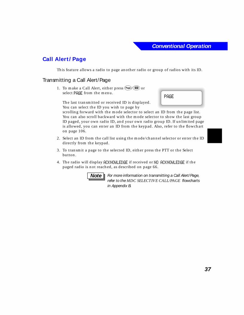
Transmitting a Call Alert/Page1. To make a Call Alert, either press P/& or
select PAGE from the menu.
The last transmitted or received ID is displayed. You can select the ID you wish to page by scrolling forward with the mode selector to select an ID from the page list. You can also scroll backward with the mode selector to show the last group ID paged, your own radio ID, and your own radio group ID. If unlimited page is allowed, you can enter an ID from the keypad. Also, refer to the flowchart on page 106.
2. Select an ID from the call list using the mode/channel selector or enter the ID directly from the keypad.
3. To transmit a page to the selected ID, either press the PTT or the Select button.
4. The radio will display ACKNOWLEDGE if received or NO ACKNOWLEDGE if the paged radio is not reached, as described on page 66.
PAGE
For more information on transmitting a Call Alert/Page, refer to the MDC SELECTIVE CALL/PAGE flowcharts in Appendix B.
Note
Conventional Operation
38
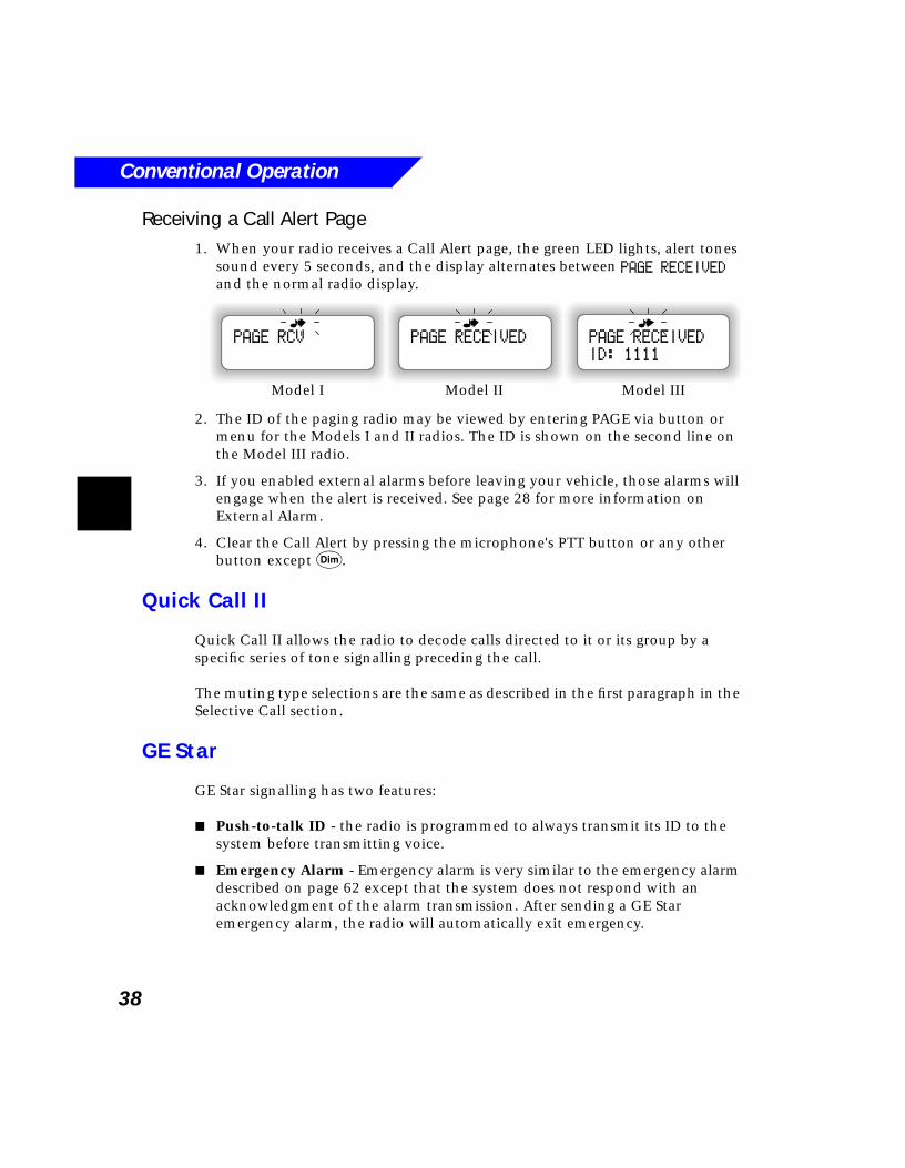
Receiving a Call Alert Page 1. When your radio receives a Call Alert page, the green LED lights, alert tones
sound every 5 seconds, and the display alternates between PAGE RECEIVED and the normal radio display.
2. The ID of the paging radio may be viewed by entering PAGE via button or menu for the Models I and II radios. The ID is shown on the second line on the Model III radio.
3. If you enabled external alarms before leaving your vehicle, those alarms will engage when the alert is received. See page 28 for more information on External Alarm.
4. Clear the Call Alert by pressing the microphone's PTT button or any other button except D.
Quick Call II
Quick Call II allows the radio to decode calls directed to it or its group by a specific series of tone signalling preceding the call.
The muting type selections are the same as described in the first paragraph in the Selective Call section.
GE Star
GE Star signalling has two features:
■ Push-to-talk ID - the radio is programmed to always transmit its ID to the system before transmitting voice.
■ Emergency Alarm - Emergency alarm is very similar to the emergency alarm described on page 62 except that the system does not respond with an acknowledgment of the alarm transmission. After sending a GE Star emergency alarm, the radio will automatically exit emergency.
Model I Model II Model III
PAGE RECEIVED
ID: 1111
PAGE RECEIVEDPAGE RCV
Conventional Operation
39
Singletone Repeater Access
Either a manual button press or automatic transmission of a specific tone will identify the repeater to which the radio desires to transmit. This feature is used when two repeaters in close proximity on the same frequency are used to process transmissions. The radio will select which repeater will broadcast its transmission.
If manual repeater access is enabled, you must press the repeater access button prior to voice transmission to specify the repeater on which you wish to transmit. All non-voice transmission (such as status, message, or call alert) will automatically send the repeater access; a button press is not needed.
If automatic repeater access is enabled, the radio will automatically send a repeater access tone prior to all transmissions.
Telephone Interconnect
Your radio may be equipped with Telephone Interconnect, which allows you to make calls to landline telephones through the repeater.
1. Press p/$to activate Telephone Interconnect.
2. When initiating a phone call on a conventional system, you will usually need a special code to gain access to the repeater’s telephone interconnect function. This access code is transmitted in one of four ways, depending on how your radio is programmed:
- Immediate - The radio automatically sends a pre-stored access code as soon as you press p/$.
1. The mobile operator can either talk or listen at one time, whereas the landline user has duplex (talk and listen) operation. This means a mobile operator who is speaking will not hear an interruption from the landline user. Therefore, the landline user should be advised to listen for the beep before speaking.
2. Both parties will hear a high-pitched alert tone fifteen seconds before the call times out; you will then have fifteen seconds to complete your conversation.
Notes
Conventional Operation
40
- Manual - You must enter the access code, using the keypad, then press s/8 or the PTT button to transmit the code.
- Manual Live - You must enter the access code, using the keypad. Each digit of the code will be transmitted as it is entered.
- Delayed - You must press s/8 or the PTT button and the radio sends the stored access code.
3. The radio supports three dialing options:
- Last Dialed Number - The last dialed number is shown on the display. Press s/8 or the PTT to call this number. If your radio is equipped with buffered dialing, you can replace the number in the display by entering a new number. To insert a pause into the dialing stream, press #, then *. A PPPP will be displayed to indicate the pause.
- Dialing List - To select a number from the dialing list, use the mode/channel selector to scroll to the number you wish to call. The display will show the name, alternating with the phone number.
- Direct Entry - With a keypad (either Model III keypad or keypad microphone) and unlimited phone operation enabled, you can directly enter the number you wish to dial. You can enter a new number only while the last dialed number is displayed. If you are in the call list, press the zero (0) key to return to the last dialed number display.
For more information on dialing options, refer to the flowcharts on page 102 (Phone List Direct Entry),page 103 (Phone List Scrolling), and page 104 (Phone List Editing).
4. Press s/8 or the PTT to call the displayed number (unless Live Dialing is enabled).
5. When the call is completed, press h/6 or p/$ to de-access the phone and return to normal operation.
If no dial tone sounds after transmitting the access code, telephone interconnect might not be functioning. Press h/6 or p/$ to hang up.
Note
41
5Trunking Operation
What’s In This Chapter?■ Transmitting - describes how to transmit on a selected trunked mode
and how to handle a busy or out-of-range condition (page 42)
■ Private Call - describes how to carry on a conversation that is heard only by the two radios involved (page 43)
■ Call Alert Page - describes how to send an alert to another radio with an acknowledgment if the alert was successful (page 47)
■ One-Touch Button - describes how to access and automatically transmit a specific feature by pressing only one button (page 48)
■ Dynamic Regrouping - describes how the dispatcher can temporarily reassign selected individual radios to a new group (page 49)
■ Automatic Multiple-Site Switching - describes how AMSS extends communications beyond the reach of a single trunked site (page 51)
■ SmartZone - describes the extended trunking features available with SmartZone (page 53)
■ Voice on Control Operation - describes the feature that allows the control channel to be used for voice operation (page 54)
■ Trunked Type II Announcement - describes how to make announcements to the entire talkgroup and monitor calls (page 54)
■ Failsoft - describes what happens if a central controller fails (page 55)
■ Telephone interconnect - describes how to use the Telephone feature on a trunked system (page 56)
Trunking Operation
42
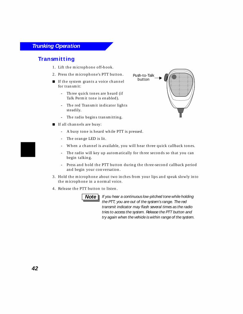
Transmitting 1. Lift the microphone off-hook.
2. Press the microphone's PTT button.
■ If the system grants a voice channel for transmit:
- Three quick tones are heard (if Talk Permit tone is enabled).
- The red Transmit indicator lights steadily.
- The radio begins transmitting.
■ If all channels are busy:
- A busy tone is heard while PTT is pressed.
- The orange LED is lit.
- When a channel is available, you will hear three quick callback tones.
- The radio will key up automatically for three seconds so that you can begin talking.
- Press and hold the PTT button during the three-second callback period and begin your conversation.
3. Hold the microphone about two inches from your lips and speak slowly into the microphone in a normal voice.
4. Release the PTT button to listen.
Push-to-Talkbutton
����������������������������
If you hear a continuous low-pitched tone while holding the PTT, you are out of the system's range. The red transmit indicator may flash several times as the radio tries to access the system. Release the PTT button and try again when the vehicle is within range of the system.
Note
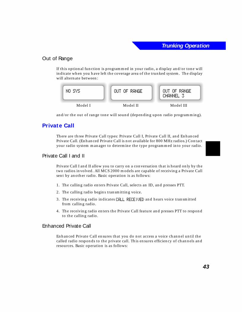
Trunking Operation
43
Out of Range
If this optional function is programmed in your radio, a display and/or tone will indicate when you have left the coverage area of the trunked system. The display will alternate between:
and/or the out of range tone will sound (depending upon radio programming).
Private Call
There are three Private Call types: Private Call I, Private Call II, and Enhanced Private Call. (Enhanced Private Call is not available for 800 MHz radios.) Contact your radio system manager to determine the type programmed into your radio.
Private Call I and II
Private Call I and II allow you to carry on a conversation that is heard only by the two radios involved. All MCS 2000 models are capable of receiving a Private Call sent by another radio. Basic operation is as follows:
1. The calling radio enters Private Call, selects an ID, and presses PTT.
2. The calling radio begins transmitting voice.
3. The receiving radio indicates CALL RECEIVED and hears voice transmitted from calling radio.
4. The receiving radio enters the Private Call feature and presses PTT to respond to the calling radio.
Enhanced Private Call
Enhanced Private Call ensures that you do not access a voice channel until the called radio responds to the private call. This ensures efficiency of channels and resources. Basic operation is as follows:
OUT OF RANGE
CHANNEL 3
OUT OF RANGENO SYS
Model I Model II Model III
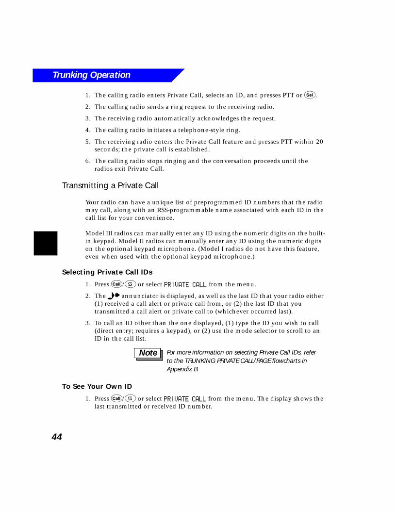
Trunking Operation
44
1. The calling radio enters Private Call, selects an ID, and presses PTT or s.
2. The calling radio sends a ring request to the receiving radio.
3. The receiving radio automatically acknowledges the request.
4. The calling radio initiates a telephone-style ring.
5. The receiving radio enters the Private Call feature and presses PTT within 20 seconds; the private call is established.
6. The calling radio stops ringing and the conversation proceeds until the radios exit Private Call.
Transmitting a Private Call
Your radio can have a unique list of preprogrammed ID numbers that the radio may call, along with an RSS-programmable name associated with each ID in the call list for your convenience.
Model III radios can manually enter any ID using the numeric digits on the built-in keypad. Model II radios can manually enter any ID using the numeric digits on the optional keypad microphone. (Model I radios do not have this feature, even when used with the optional keypad microphone.)
Selecting Private Call IDs
1. Press C/9 or select PRIVATE CALL from the menu.
2. The e annunciator is displayed, as well as the last ID that your radio either (1) received a call alert or private call from, or (2) the last ID that you transmitted a call alert or private call to (whichever occurred last).
3. To call an ID other than the one displayed, (1) type the ID you wish to call (direct entry; requires a keypad), or (2) use the mode selector to scroll to an ID in the call list.
To See Your Own ID
1. Press C/9 or select PRIVATE CALL from the menu. The display shows the last transmitted or received ID number.
For more information on selecting Private Call IDs, refer to the TRUNKING PRIVATE CALL/PAGE flowcharts in Appendix B.
Note
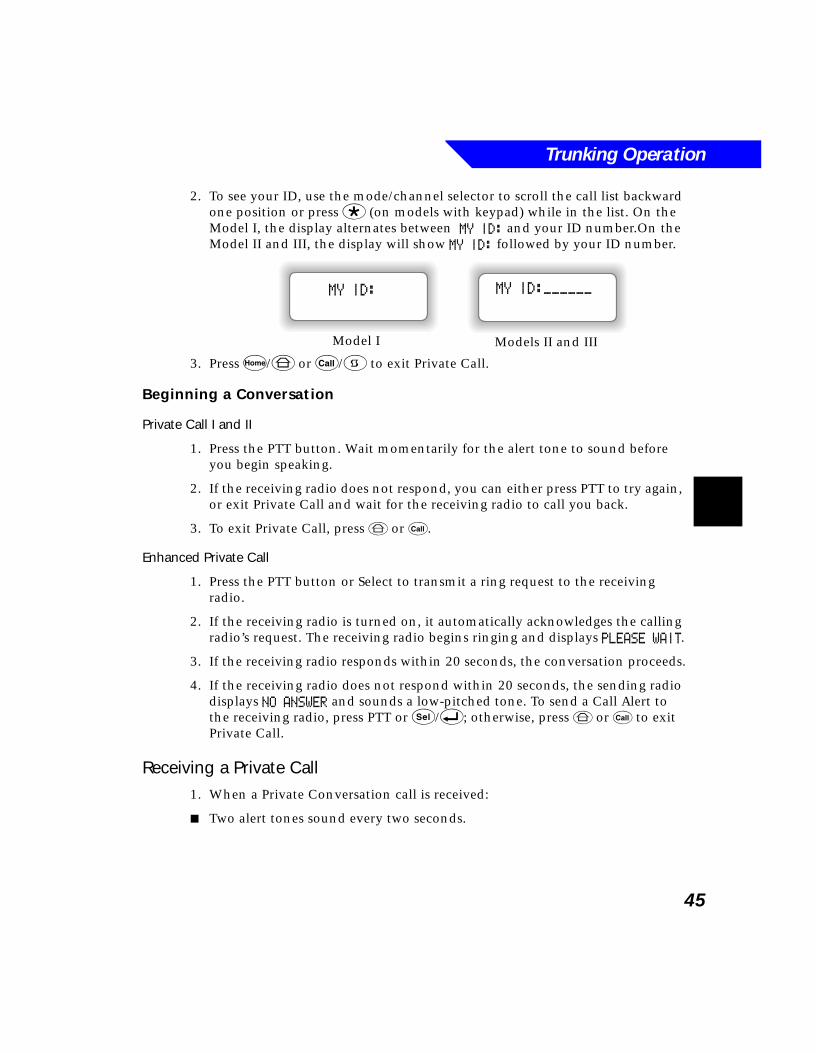
Trunking Operation
45
2. To see your ID, use the mode/channel selector to scroll the call list backward one position or press * (on models with keypad) while in the list. On the Model I, the display alternates between MY ID: and your ID number.On the Model II and III, the display will show MY ID: followed by your ID number.
3. Press h/6 or C/9 to exit Private Call.
Beginning a Conversation
Private Call I and II
1. Press the PTT button. Wait momentarily for the alert tone to sound before you begin speaking.
2. If the receiving radio does not respond, you can either press PTT to try again, or exit Private Call and wait for the receiving radio to call you back.
3. To exit Private Call, press 6 or C.
Enhanced Private Call
1. Press the PTT button or Select to transmit a ring request to the receiving radio.
2. If the receiving radio is turned on, it automatically acknowledges the calling radio’s request. The receiving radio begins ringing and displays PLEASE WAIT.
3. If the receiving radio responds within 20 seconds, the conversation proceeds.
4. If the receiving radio does not respond within 20 seconds, the sending radio displays NO ANSWER and sounds a low-pitched tone. To send a Call Alert to the receiving radio, press PTT or s/8; otherwise, press 6 or C to exit Private Call.
Receiving a Private Call1. When a Private Conversation call is received:
■ Two alert tones sound every two seconds.
MY ID:
Model I Models II and III
MY ID:______
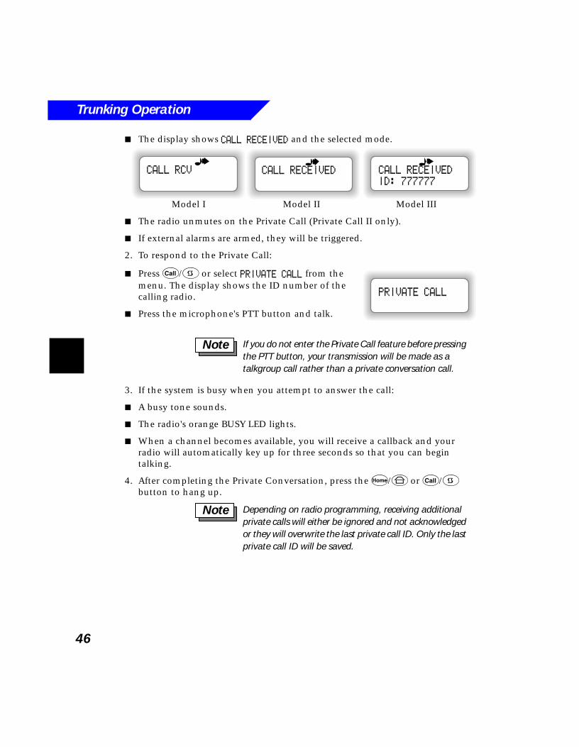
Trunking Operation
46
■ The display shows CALL RECEIVED and the selected mode.
■ The radio unmutes on the Private Call (Private Call II only).
■ If external alarms are armed, they will be triggered.
2. To respond to the Private Call:
■ Press C/9 or select PRIVATE CALL from the menu. The display shows the ID number of the calling radio.
■ Press the microphone's PTT button and talk.
3. If the system is busy when you attempt to answer the call:
■ A busy tone sounds.
■ The radio's orange BUSY LED lights.
■ When a channel becomes available, you will receive a callback and your radio will automatically key up for three seconds so that you can begin talking.
4. After completing the Private Conversation, press the h/6 or C/9 button to hang up.
CALL RECEIVED
ID: 777777
CALL RECEIVEDCALL RCV
Model I Model II Model III
PRIVATE CALL
If you do not enter the Private Call feature before pressing the PTT button, your transmission will be made as a talkgroup call rather than a private conversation call.
Note
Depending on radio programming, receiving additional private calls will either be ignored and not acknowledged or they will overwrite the last private call ID. Only the last private call ID will be saved.
Note
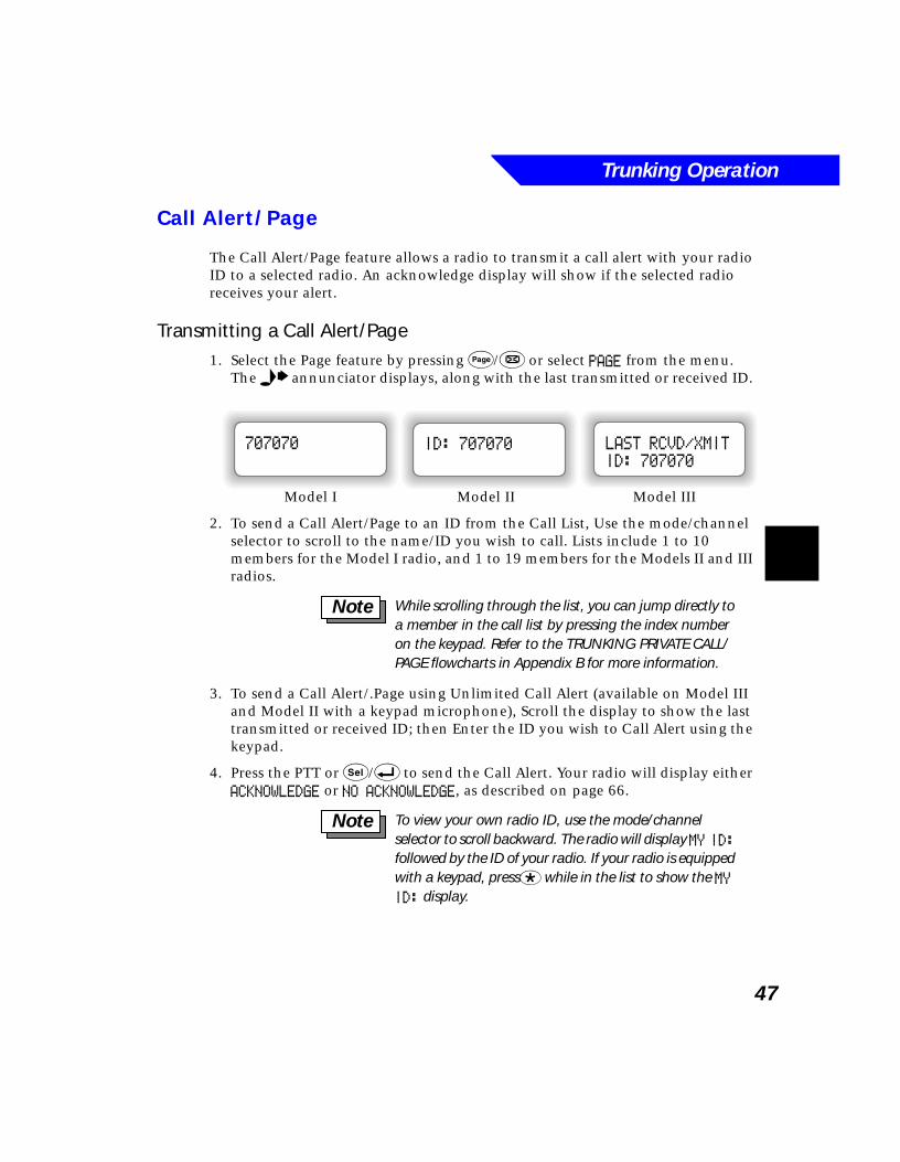
Trunking Operation
47
Call Alert/Page
The Call Alert/Page feature allows a radio to transmit a call alert with your radio ID to a selected radio. An acknowledge display will show if the selected radio receives your alert.
Transmitting a Call Alert/Page1. Select the Page feature by pressing P/& or select PAGE from the menu.
The e annunciator displays, along with the last transmitted or received ID.
2. To send a Call Alert/Page to an ID from the Call List, Use the mode/channel selector to scroll to the name/ID you wish to call. Lists include 1 to 10 members for the Model I radio, and 1 to 19 members for the Models II and III radios.
3. To send a Call Alert/.Page using Unlimited Call Alert (available on Model III and Model II with a keypad microphone), Scroll the display to show the last transmitted or received ID; then Enter the ID you wish to Call Alert using the keypad.
4. Press the PTT or s/8 to send the Call Alert. Your radio will display either ACKNOWLEDGE or NO ACKNOWLEDGE, as described on page 66.
LAST RCVD/XMIT
ID: 707070
ID: 707070707070
Model I Model II Model III
While scrolling through the list, you can jump directly to a member in the call list by pressing the index number on the keypad. Refer to the TRUNKING PRIVATE CALL/PAGE flowcharts in Appendix B for more information.
Note
To view your own radio ID, use the mode/channel selector to scroll backward. The radio will display MY ID: followed by the ID of your radio. If your radio is equipped with a keypad, press* while in the list to show the MY ID: display.
Note
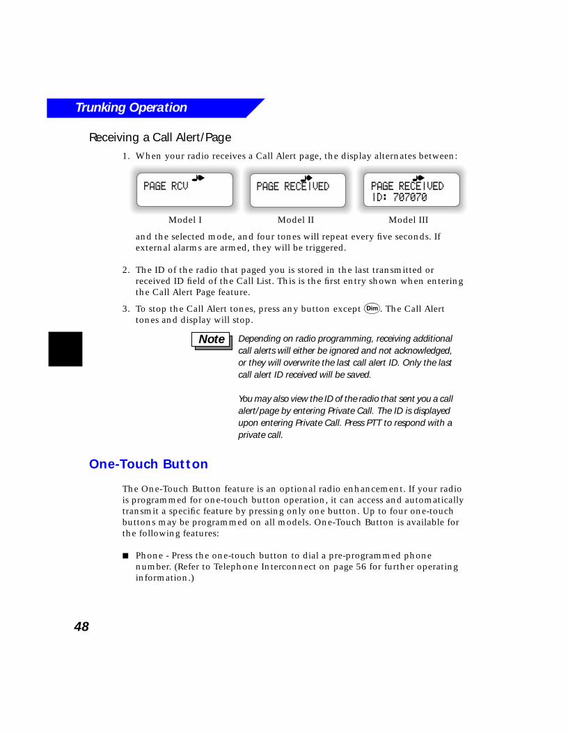
Trunking Operation
48
Receiving a Call Alert/Page1. When your radio receives a Call Alert page, the display alternates between:
and the selected mode, and four tones will repeat every five seconds. If external alarms are armed, they will be triggered.
2. The ID of the radio that paged you is stored in the last transmitted or received ID field of the Call List. This is the first entry shown when entering the Call Alert Page feature.
3. To stop the Call Alert tones, press any button except D. The Call Alert tones and display will stop.
One-Touch Button
The One-Touch Button feature is an optional radio enhancement. If your radio is programmed for one-touch button operation, it can access and automatically transmit a specific feature by pressing only one button. Up to four one-touch buttons may be programmed on all models. One-Touch Button is available for the following features:
■ Phone - Press the one-touch button to dial a pre-programmed phone number. (Refer to Telephone Interconnect on page 56 for further operating information.)
PAGE RECEIVED
ID: 707070
PAGE RECEIVEDPAGE RCV
Model I Model II Model III
Depending on radio programming, receiving additional call alerts will either be ignored and not acknowledged, or they will overwrite the last call alert ID. Only the last call alert ID received will be saved.
You may also view the ID of the radio that sent you a call alert/page by entering Private Call. The ID is displayed upon entering Private Call. Press PTT to respond with a private call.
Note
Trunking Operation
49
■ Call Alert Page - Press the one-touch button to send a Call Alert Page to a pre-programmed radio ID. (Refer to Call Alert/Page on page 47 for further operating information.)
■ Status or Message - Press the one-touch button to send a pre-programmed status or message. (Refer to Status/Message Transmission on page 75 for further operating information.)
■ Private Call - Press the one-touch button to initiate a Private Call to a pre-programmed radio ID. For Private Call II, you must also press the PTT to begin the Private Call. (Refer to Private Call on page 43 for further operating information.)
Dynamic Regrouping
The dynamic regrouping feature allows the dispatcher to temporarily reassign selected individual radios to a new group.
Receiving a Dynamic Regrouping Assignment
The following occurs when your radio receives a dynamic regrouping assignment:
1. A unique series of tones sounds to alert you that your radio has been dynamically regrouped.
2. The display shows the new dynamic mode name assignment and your radio now operates on this new group.
3. After the dispatcher releases your radio from the dynamic assignment, your radio returns to the mode you were on before being dynamically regrouped.
Select Enabled and Disabled
Two types of dynamic regrouping are possible:
Select Enabled - After being dynamically regrouped, a select-enabled radio may make mode changes using the mode/channel selector to any mode in the radio, including the dynamic group.
Select Disabled - A select-disabled radio is forced to remain on the dynamic group and cannot change modes. The channel selector will not function.
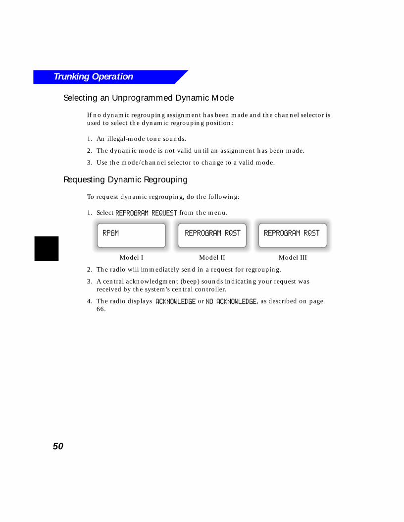
Trunking Operation
50
Selecting an Unprogrammed Dynamic Mode
If no dynamic regrouping assignment has been made and the channel selector is used to select the dynamic regrouping position:
1. An illegal-mode tone sounds.
2. The dynamic mode is not valid until an assignment has been made.
3. Use the mode/channel selector to change to a valid mode.
Requesting Dynamic Regrouping
To request dynamic regrouping, do the following:
1. Select REPROGRAM REQUEST from the menu.
2. The radio will immediately send in a request for regrouping.
3. A central acknowledgment (beep) sounds indicating your request was received by the system's central controller.
4. The radio displays ACKNOWLEDGE or NO ACKNOWLEDGE, as described on page 66.
REPROGRAM RQST
Model III
REPROGRAM RQSTRPGM
Model IIModel I
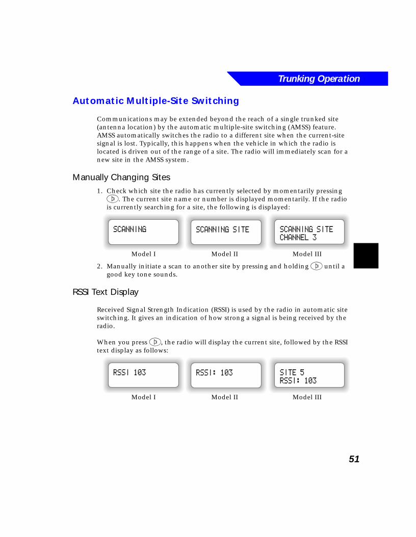
Trunking Operation
51
Automatic Multiple-Site Switching
Communications may be extended beyond the reach of a single trunked site (antenna location) by the automatic multiple-site switching (AMSS) feature. AMSS automatically switches the radio to a different site when the current-site signal is lost. Typically, this happens when the vehicle in which the radio is located is driven out of the range of a site. The radio will immediately scan for a new site in the AMSS system.
Manually Changing Sites1. Check which site the radio has currently selected by momentarily pressing 2. The current site name or number is displayed momentarily. If the radio is currently searching for a site, the following is displayed:
2. Manually initiate a scan to another site by pressing and holding 2 until a good key tone sounds.
RSSI Text Display
Received Signal Strength Indication (RSSI) is used by the radio in automatic site switching. It gives an indication of how strong a signal is being received by the radio.
When you press 2, the radio will display the current site, followed by the RSSI text display as follows:
SCANNING SITE
CHANNEL 3
SCANNING SITESCANNING
Model I Model II Model III
SITE 5
RSSI: 103
RSSI: 103RSSI 103
Model I Model II Model III
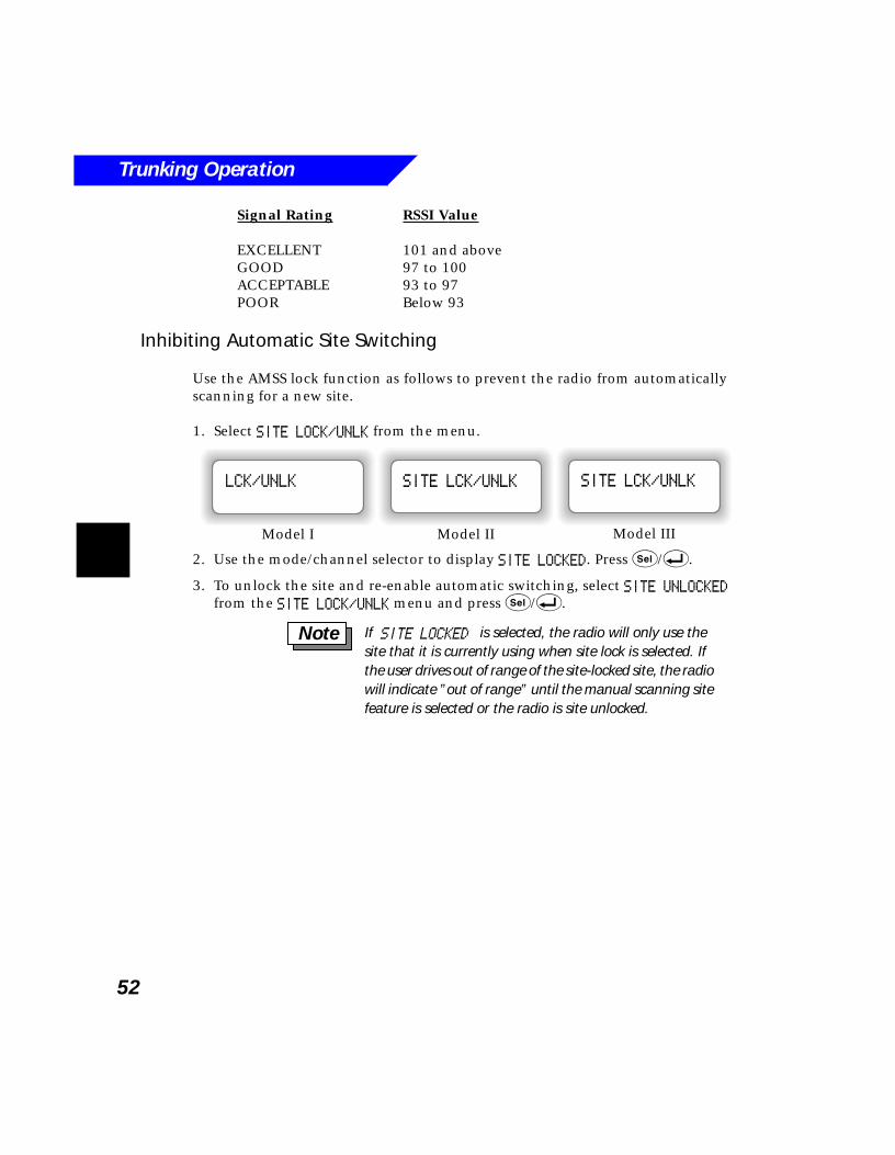
Trunking Operation
52
Signal Rating RSSI Value
EXCELLENT 101 and aboveGOOD 97 to 100ACCEPTABLE 93 to 97POOR Below 93
Inhibiting Automatic Site Switching
Use the AMSS lock function as follows to prevent the radio from automatically scanning for a new site.
1. Select SITE LOCK/UNLK from the menu.
2. Use the mode/channel selector to display SITE LOCKED. Press s/8.
3. To unlock the site and re-enable automatic switching, select SITE UNLOCKED from the SITE LOCK/UNLK menu and press s/8.
SITE LCK/UNLKLCK/UNLK
Model I Model II
SITE LCK/UNLK
Model III
If SITE LOCKED is selected, the radio will only use the site that it is currently using when site lock is selected. If the user drives out of range of the site-locked site, the radio will indicate ”out of range” until the manual scanning site feature is selected or the radio is site unlocked.
Note
Trunking Operation
53
SmartZone Features
SmartZone provides the following features:
■ SmartZone enhances AMSS operations by allowing more sites in the trunked system and only allocating channels at sites where users are affiliated. All SmartZone radios will automatically affiliate upon switching sites and will de-affiliate from the system when they are powered down.
■ SmartZone improves site switching by automatically switching the radio to a different site whenever a significantly better site is found based on site preferences and signal strengths. SmartZone radios are constantly looking for better sites for operation.
■ SmartZone automatic site switching keeps the radio in good communication range at all times when the radio is in range of the system. AMSS manual site switching functions are available in SmartZone; however, their use is discouraged as they can adversely affect SmartZone automatic switching operation.
Busy Override In a SmartZone System
It is possible for one or more sites to have all available repeaters in use. If a radio user tries to make a call and members of his talkgroup are present at a busy site, the radio initiating the call will receive a system busy signal. The initiating radio can override the busy signal to immediately talk to talkgroup members at all available sites, with those at busy sites being brought into the conversation when repeaters at the busy sites become available.
To send a busy override:
1. Upon receiving the system busy tone, release the PTT and then immediately press the PTT again.
2. The busy tones will be heard for a few seconds and then a good-key-chirp tone will be heard.
3. The busy override is sent to the system.
4. The system will place the call or another system busy will be sent if the busy cannot be overridden.
Using busy-override means that not everyone in your group will hear the call.
Note
Trunking Operation
54
Site Trunking
In a SmartZone system, if a site is operating in local mode where transmissions are between users at a single site only, the radio will display SITE TRUNKING alternating with the selected mode. When operating in site trunking, the radio will be allowed to send and receive normal trunking calls; however, the radio will only be able to communicate with other radios operating on this site.
Full Spectrum Scan
Because SmartZone systems can have many sites, and future sites may be added to existing SmartZone systems, the radio needs to be able to find sites that are not programmed into its memory. If full spectrum scan is enabled, and if the radio cannot find a site from its memory on power-up, it can search the current channel band looking for a site.
Note that SmartZone radios also receive information about sites over-the-air, and all site information is stored upon power-down. Full spectrum scan is only used when the radio cannot find a site in its memory on power-up.
Voice On Control Operation
Voice on control (VOC) is a system feature that allows a control channel to become a voice channel when all other repeaters are being used. If the system has sites that operate in VOC mode, the radio must be programmed for VOC operation to operate properly.
Trunked Type II Announcement
The announcement capability allows a user to make announcements to the entire user group, as well as to monitor talkgroup calls and other announcements.
To initiate an announcement, do the following:
1. If your radio has been programmed to allow announcement calls, use the mode/channel selector to scroll to the announcement-group mode.
2. Press the microphone's PTT button to initiate the announcement.
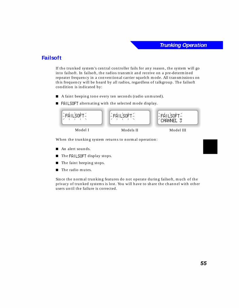
Trunking Operation
55
Failsoft
If the trunked system's central controller fails for any reason, the system will go into failsoft. In failsoft, the radios transmit and receive on a pre-determined repeater frequency in a conventional carrier squelch mode. All transmissions on this frequency will be heard by all radios, regardless of talkgroup. The failsoft condition is indicated by:
■ A faint beeping tone every ten seconds (radio unmuted).
■ FAILSOFT alternating with the selected mode display.
When the trunking system returns to normal operation:
■ An alert sounds.
■ The FAILSOFT display stops.
■ The faint beeping stops.
■ The radio mutes.
Since the normal trunking features do not operate during failsoft, much of the privacy of trunked systems is lost. You will have to share the channel with other users until the failure is corrected.
FAILSOFT
CHANNEL 3
FAILSOFT
Models II Model III
FAILSOFT
Model I
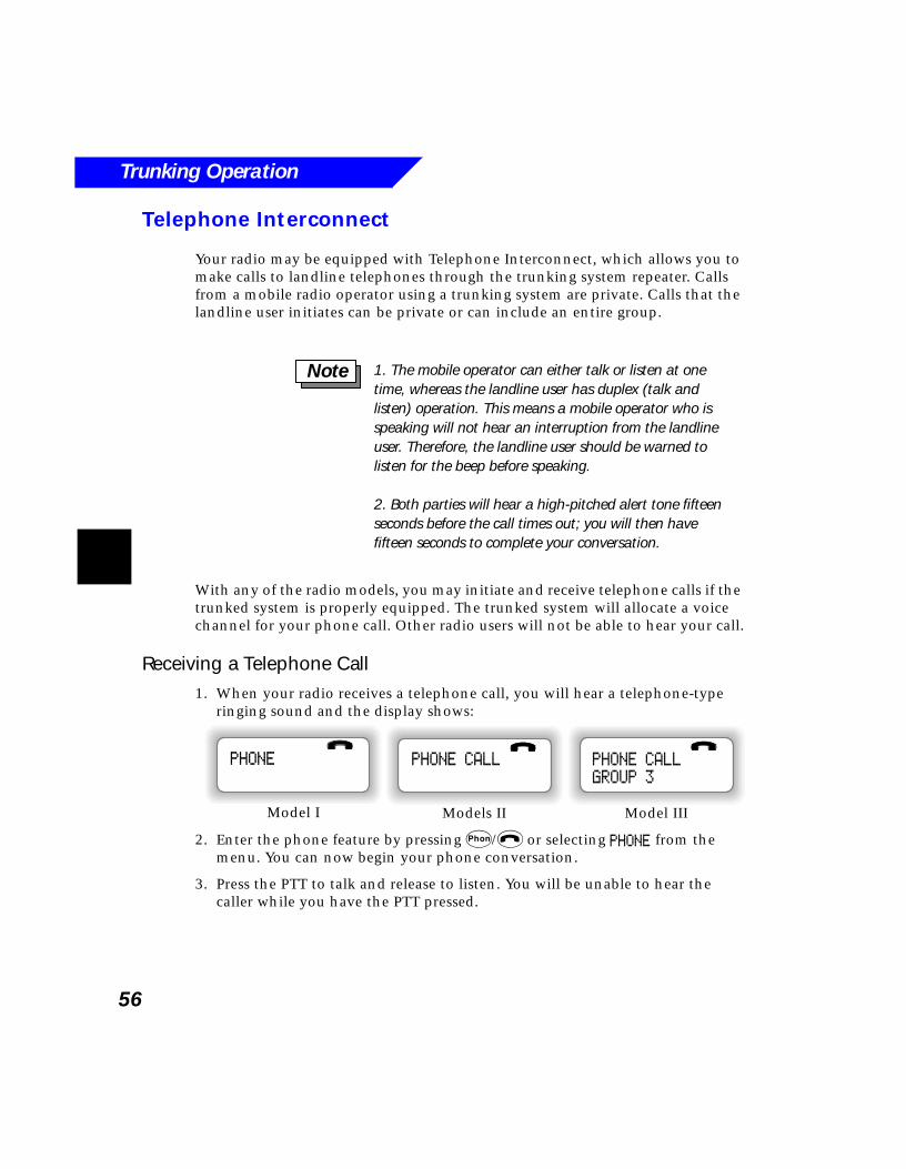
Trunking Operation
56
Telephone Interconnect
Your radio may be equipped with Telephone Interconnect, which allows you to make calls to landline telephones through the trunking system repeater. Calls from a mobile radio operator using a trunking system are private. Calls that the landline user initiates can be private or can include an entire group.
With any of the radio models, you may initiate and receive telephone calls if the trunked system is properly equipped. The trunked system will allocate a voice channel for your phone call. Other radio users will not be able to hear your call.
Receiving a Telephone Call1. When your radio receives a telephone call, you will hear a telephone-type
ringing sound and the display shows:
2. Enter the phone feature by pressing p/$ or selecting PHONE from the menu. You can now begin your phone conversation.
3. Press the PTT to talk and release to listen. You will be unable to hear the caller while you have the PTT pressed.
1. The mobile operator can either talk or listen at one time, whereas the landline user has duplex (talk and listen) operation. This means a mobile operator who is speaking will not hear an interruption from the landline user. Therefore, the landline user should be warned to listen for the beep before speaking.
2. Both parties will hear a high-pitched alert tone fifteen seconds before the call times out; you will then have fifteen seconds to complete your conversation.
Note
PHONE CALL
GROUP 3
PHONE CALL
Models II Model III
PHONE
Model I
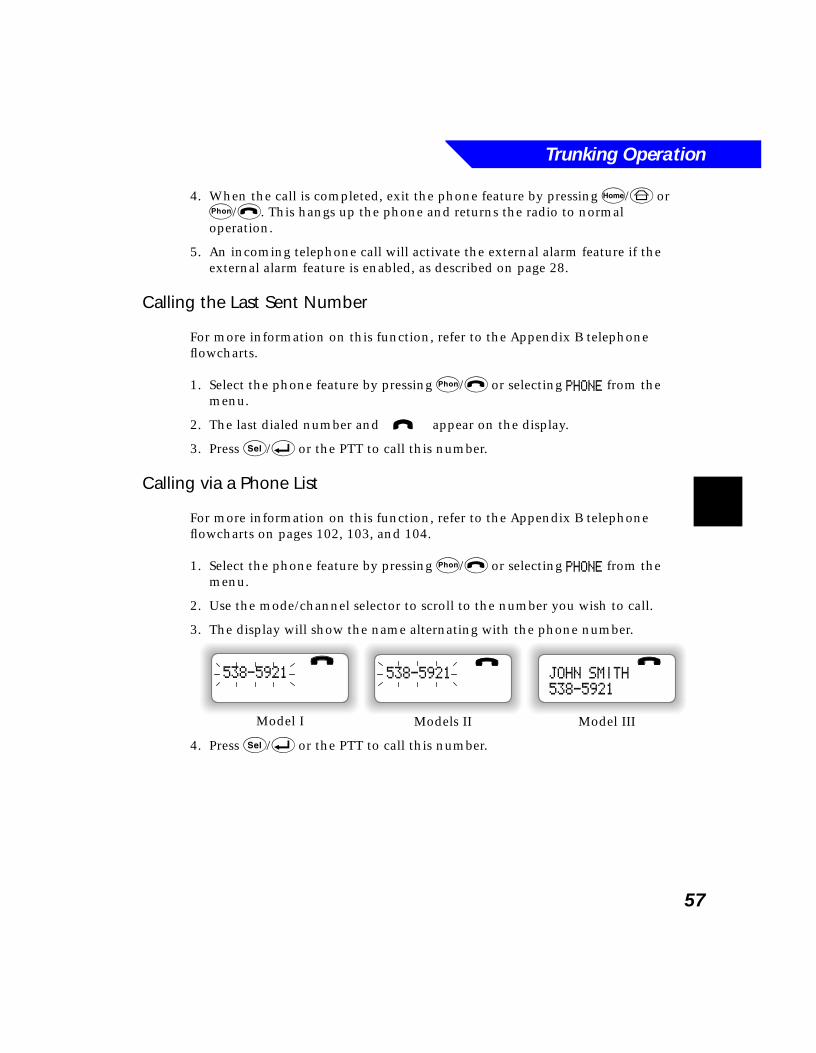
Trunking Operation
57
4. When the call is completed, exit the phone feature by pressing h/6 or p/$. This hangs up the phone and returns the radio to normal operation.
5. An incoming telephone call will activate the external alarm feature if the external alarm feature is enabled, as described on page 28.
Calling the Last Sent Number
For more information on this function, refer to the Appendix B telephone flowcharts.
1. Select the phone feature by pressing p/$ or selecting PHONE from the menu.
2. The last dialed number and i appear on the display.
3. Press s/8 or the PTT to call this number.
Calling via a Phone List
For more information on this function, refer to the Appendix B telephone flowcharts on pages 102, 103, and 104.
1. Select the phone feature by pressing p/$ or selecting PHONE from the menu.
2. Use the mode/channel selector to scroll to the number you wish to call.
3. The display will show the name alternating with the phone number.
4. Press s/8 or the PTT to call this number.
JOHN SMITH
538-5921
538-5921
Models II Model III
538-5921
Model I
Trunking Operation
58
Calling via Direct Keypad Entry
Direct keypad entry is available on a Model III (the Model I and Model II require an optional keypad microphone). For more information on this function, refer to the Appendix B telephone flowcharts on pages 102, 103, and 104.
1. Select the phone feature by pressing p/$ or selecting PHONE from the menu.
2. The last dialed number and i appear on the display.
3. Enter the number you wish to call.
Correcting Numbers
When direct dialing via keypad, you can make corrections to a number as follows if you have buffered dialing.
For models equipped with Buffered Dialing, Scroll backward with the mode/channel selector or press # twice to delete the previously entered digit. For models equipped with Live Dialing only, you must exit and re-enter the Phone feature to start dialing again.
Editing the Phone List
Refer to page 74 for information on editing the phone list.
Phone Not Available1. If you are out of range of the trunked system, or phone features are not
available, the radio displays NO PHONE and sounds a continuous low-pitched tone.
2. Press h/6 or p/$ to exit Telephone Interconnect and resume normal radio operation.
You may enter a new number only while the last sent number is displayed. If you are in the call list, press the zero (0) key to return to the last sent number display.
Note
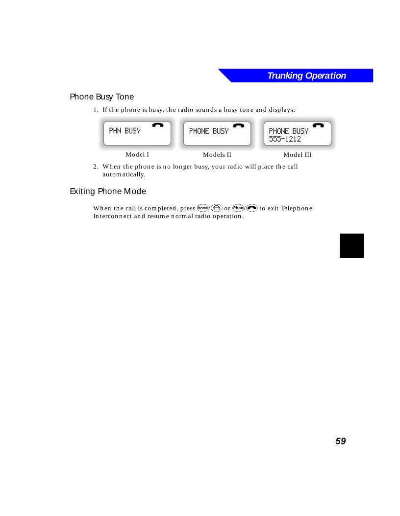
Trunking Operation
59
Phone Busy Tone1. If the phone is busy, the radio sounds a busy tone and displays:
2. When the phone is no longer busy, your radio will place the call automatically.
Exiting Phone Mode
When the call is completed, press h/6 or p/$ to exit Telephone Interconnect and resume normal radio operation.
PHONE BUSY
555-1212
PHONE BUSY
Models II Model III
PHN BUSY
Model I

Trunking Operation
60
61
6Features Common to
Conventional and TrunkedOperation
What’s In This Chapter?■ Emergency - describes how to send and receive emergency alarms and
emergency calls (page 62)
■ Transmission Received - Acknowledge/No Acknowledge - describes how the central system responds to a request from a radio (page 66)
■ Scanning - describes how to turn the scan function on and off, the differences between priority and non-priority modes, the operation of talkgroup scan and auto-scan, and how to edit a Scan List (page 67)
■ Editing the Call List - describes how to edit your radio’s call list (page 73)
■ Editing the Phone List - describes how to edit your radio’s telephone list (page 74)
■ Status/Message Transmission - describes how to send status and messages to the dispatcher over the trunking control channel (page 75)
■ Handset Operation - describes how to use the radio’s optional handset (page 76)
Common Features
62
EmergencyEmergency may be programmed to send an alarm, a call, or both an alarm and a call. There are three different types of emergency activation available for your radio:
■ A built-in emergency button (1) on the radio’s control head.
■ An optional footswitch.
■ An optional external emergency push-button.
Refer to the MCS 2000 Accessories Guide for more information on the emergency footswitch and emergency push-button. See back pages of this manual for publication ordering information.
Emergency Alarm
The emergency alarm feature sends a data transmission on the trunked control channel to alert the dispatcher of your emergency condition and identify your radio ID. If emergency alarm only is enabled, the radio will return to normal operation after sending the emergency alarm transmission.
1. Press the emergency button 1.
2. The red LED lights and the emergency is transmitted.
3. A central acknowledgment (beep) indicates that the alarm was received by the trunked system's central controller.
4. A dispatcher acknowledgment (four beeps) and an ACK RECEIVED display indicate that the alarm was received by the dispatcher. Refer to page 66 for more information.
!C a u t i o n
The Emergency button may be programmed by RSS to require an extended press to activate Emergency. Contact your radio system manager for programming information.
If both Emergency Alarm and Call are enabled, the radio will enter Emergency Call mode after sending the Emergency Alarm transmission.
Note
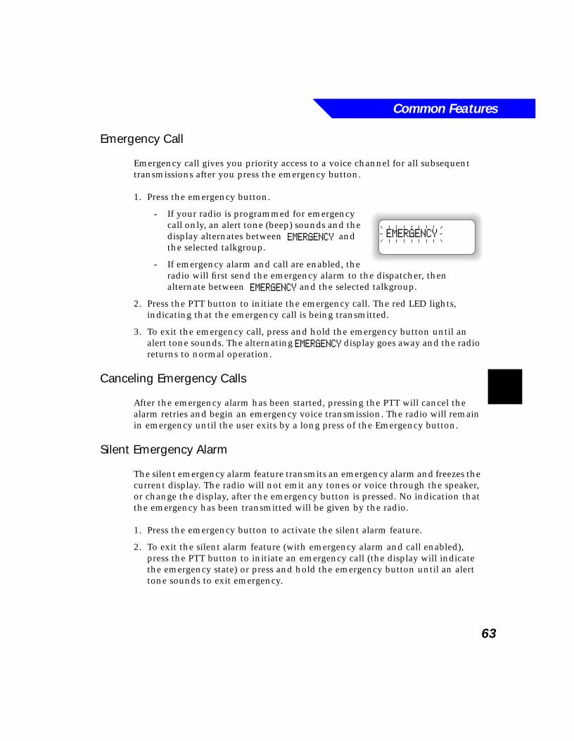
Common Features
63
Emergency Call
Emergency call gives you priority access to a voice channel for all subsequent transmissions after you press the emergency button.
1. Press the emergency button.
- If your radio is programmed for emergency call only, an alert tone (beep) sounds and the display alternates between EMERGENCY and the selected talkgroup.
- If emergency alarm and call are enabled, the radio will first send the emergency alarm to the dispatcher, then alternate between EMERGENCY and the selected talkgroup.
2. Press the PTT button to initiate the emergency call. The red LED lights, indicating that the emergency call is being transmitted.
3. To exit the emergency call, press and hold the emergency button until an alert tone sounds. The alternating EMERGENCY display goes away and the radio returns to normal operation.
Canceling Emergency Calls
After the emergency alarm has been started, pressing the PTT will cancel the alarm retries and begin an emergency voice transmission. The radio will remain in emergency until the user exits by a long press of the Emergency button.
Silent Emergency Alarm
The silent emergency alarm feature transmits an emergency alarm and freezes the current display. The radio will not emit any tones or voice through the speaker, or change the display, after the emergency button is pressed. No indication that the emergency has been transmitted will be given by the radio.
1. Press the emergency button to activate the silent alarm feature.
2. To exit the silent alarm feature (with emergency alarm and call enabled), press the PTT button to initiate an emergency call (the display will indicate the emergency state) or press and hold the emergency button until an alert tone sounds to exit emergency.
EMERGENCY
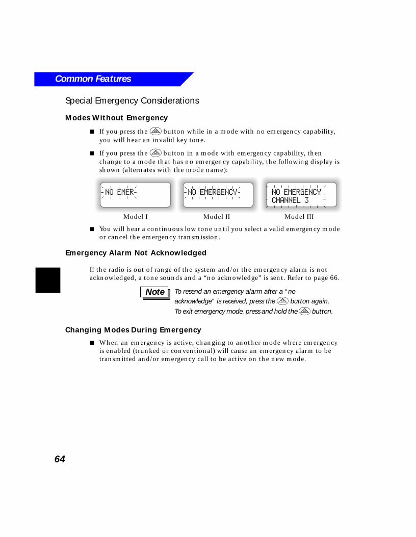
Common Features
64
Special Emergency Considerations
Modes Without Emergency
■ If you press the 1 button while in a mode with no emergency capability, you will hear an invalid key tone.
■ If you press the 1 button in a mode with emergency capability, then change to a mode that has no emergency capability, the following display is shown (alternates with the mode name):
■ You will hear a continuous low tone until you select a valid emergency mode or cancel the emergency transmission.
Emergency Alarm Not Acknowledged
If the radio is out of range of the system and/or the emergency alarm is not acknowledged, a tone sounds and a “no acknowledge” is sent. Refer to page 66.
Changing Modes During Emergency
■ When an emergency is active, changing to another mode where emergency is enabled (trunked or conventional) will cause an emergency alarm to be transmitted and/or emergency call to be active on the new mode.
NO EMERGENCY
CHANNEL 3
NO EMERGENCYNO EMER
Model I Model II Model III
To resend an emergency alarm after a “no acknowledge” is received, press the 1 button again.
To exit emergency mode, press and hold the 1 button.
Note
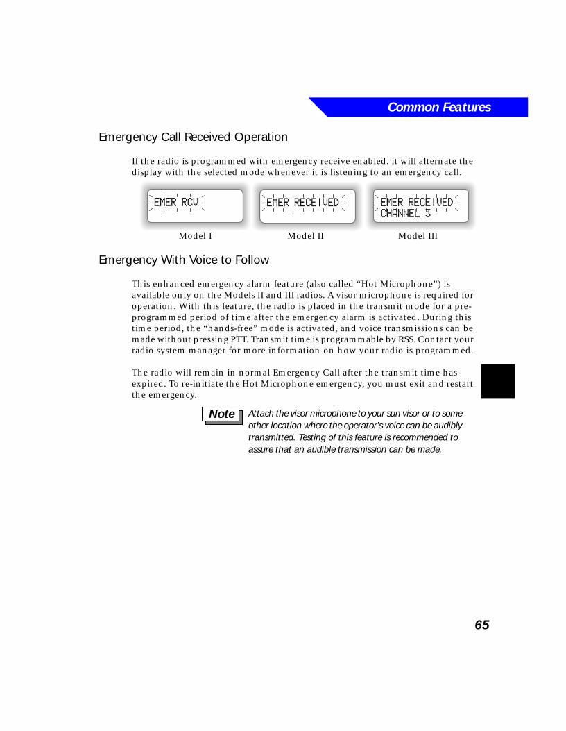
Common Features
65
Emergency Call Received Operation
If the radio is programmed with emergency receive enabled, it will alternate the display with the selected mode whenever it is listening to an emergency call.
Emergency With Voice to Follow
This enhanced emergency alarm feature (also called “Hot Microphone”) is available only on the Models II and III radios. A visor microphone is required for operation. With this feature, the radio is placed in the transmit mode for a pre-programmed period of time after the emergency alarm is activated. During this time period, the “hands-free” mode is activated, and voice transmissions can be made without pressing PTT. Transmit time is programmable by RSS. Contact your radio system manager for more information on how your radio is programmed.
The radio will remain in normal Emergency Call after the transmit time has expired. To re-initiate the Hot Microphone emergency, you must exit and restart the emergency.
EMER RECEIVED
CHANNEL 3
EMER RECEIVEDEMER RCV
Model I Model II Model III
Attach the visor microphone to your sun visor or to some other location where the operator’s voice can be audibly transmitted. Testing of this feature is recommended to assure that an audible transmission can be made.
Note
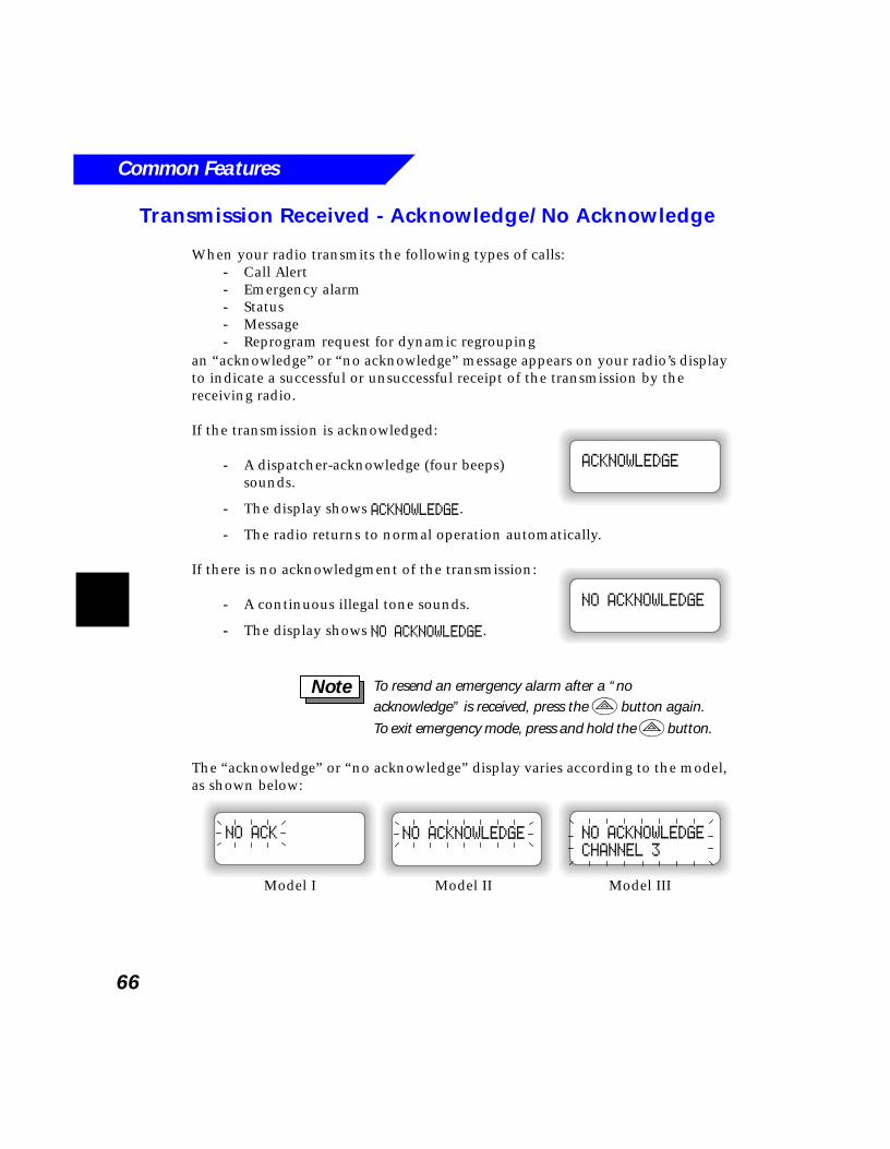
Common Features
66
Transmission Received - Acknowledge/No Acknowledge
When your radio transmits the following types of calls:- Call Alert- Emergency alarm- Status- Message- Reprogram request for dynamic regrouping
an “acknowledge” or “no acknowledge” message appears on your radio’s display to indicate a successful or unsuccessful receipt of the transmission by the receiving radio.
If the transmission is acknowledged:
- A dispatcher-acknowledge (four beeps) sounds.
- The display shows ACKNOWLEDGE.
- The radio returns to normal operation automatically.
If there is no acknowledgment of the transmission:
- A continuous illegal tone sounds.
- The display shows NO ACKNOWLEDGE.
The “acknowledge” or “no acknowledge” display varies according to the model, as shown below:
ACKNOWLEDGE
NO ACKNOWLEDGE
To resend an emergency alarm after a “no acknowledge” is received, press the 1 button again.
To exit emergency mode, press and hold the 1 button.
Note
NO ACKNOWLEDGE
CHANNEL 3
NO ACKNOWLEDGENO ACK
Model I Model II Model III
Common Features
67
Scanning
The scan feature allows you to monitor activity on multiple modes and channels. When a call is detected on a scan mode, the radio will unmute on the call until the call ends (and hang-time expires, as described on page 70) or until a higher priority call is detected.
The modes to be scanned are programmed by RSS, or you can program the modes if operator-selectable scan has been enabled, as described on page 72.
Types of Scan Lists
Two types of scan lists are available, depending on your radio’s programming: priority scan and talkgroup scan. Contact your system administrator to determine the type of scan programmed into your radio.
Priority Scan List(Trunked or Conventional)
Advantage: Allows users to designate two modes within the scan list as having higher priority or importance than other scan list members.
Disadvantage: Modes in the scan list can either be all conventional modes or all trunked modes from the same trunking system.
Scan List Members:
- Priority 1 - A call occuring on this scan list member will immediately interrupt any other calls you may be listening to. Only one scan list member may be designated as Priority 1.
- Priority 2 - A call occuring on this scan list member will immediately interrupt any other calls you may be listening to, but will not interrupt calls on the Priority 1 scan list member. Only one scan list member may be designated Priority 2.
- Non-Priority - A call occuring on these scan list members will never interrupt calls from a priority scan list member. Non-priority members all have equal importance. Multiple non-priority members are allowed.
You may miss activity on your selected mode while you are listening to a call on a scanned mode.
Note
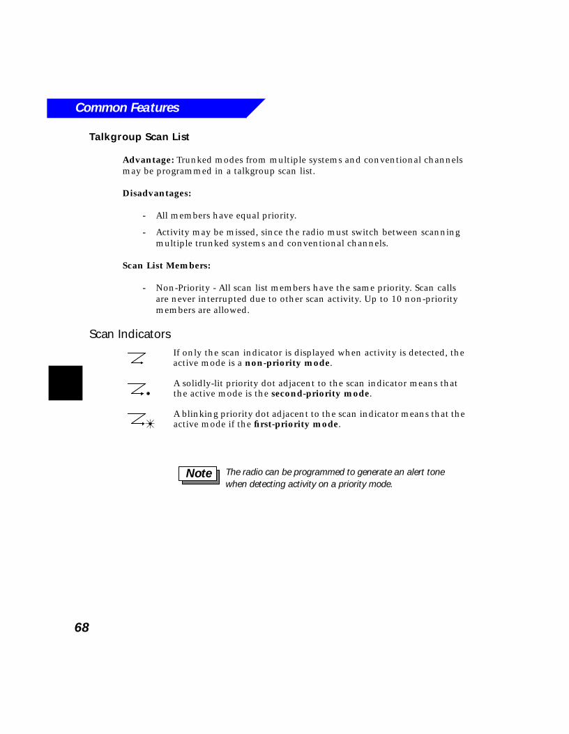
Common Features
68
Talkgroup Scan List
Advantage: Trunked modes from multiple systems and conventional channels may be programmed in a talkgroup scan list.
Disadvantages:
- All members have equal priority.
- Activity may be missed, since the radio must switch between scanning multiple trunked systems and conventional channels.
Scan List Members:
- Non-Priority - All scan list members have the same priority. Scan calls are never interrupted due to other scan activity. Up to 10 non-priority members are allowed.
Scan IndicatorsIf only the scan indicator is displayed when activity is detected, the active mode is a non-priority mode.
A solidly-lit priority dot adjacent to the scan indicator means that the active mode is the second-priority mode.
A blinking priority dot adjacent to the scan indicator means that the active mode if the first-priority mode.
The radio can be programmed to generate an alert tone when detecting activity on a priority mode.
Note
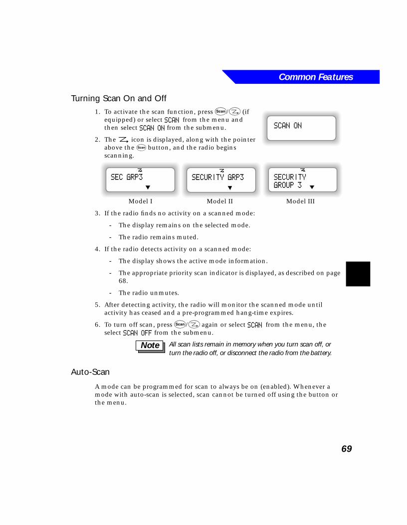
Common Features
69
Turning Scan On and Off1. To activate the scan function, press S/: (if
equipped) or select SCAN from the menu and then select SCAN ON from the submenu.
2. The icon is displayed, along with the pointer above the S button, and the radio begins scanning.
3. If the radio finds no activity on a scanned mode:
- The display remains on the selected mode.
- The radio remains muted.
4. If the radio detects activity on a scanned mode:
- The display shows the active mode information.
- The appropriate priority scan indicator is displayed, as described on page 68.
- The radio unmutes.
5. After detecting activity, the radio will monitor the scanned mode until activity has ceased and a pre-programmed hang-time expires.
6. To turn off scan, press S/: again or select SCAN from the menu, the select SCAN OFF from the submenu.
Auto-Scan
A mode can be programmed for scan to always be on (enabled). Whenever a mode with auto-scan is selected, scan cannot be turned off using the button or the menu.
SCAN ON
SECURITY
GROUP 3
SECURITY GRP3SEC GRP3
Model I Model II Model III
All scan lists remain in memory when you turn scan off, or turn the radio off, or disconnect the radio from the battery.
Note
Common Features
70
Scan Hang-Time
Scan hang-time is the amount of time the radio will continue monitoring the scanned mode after activity has ceased. This is done in case the conversation continues after a momentary pause. The radio will not resume scan until both the scanned mode’s activity and hang-time have expired. The amount of hang-time is programmable.
Nuisance Delete
To temporarily disable scanning of specific modes, you can use the nuisance delete feature. If the nuisance delete feature is enabled, non-priority scan modes can be temporarily deleted from scanning by doing the following:
1. While the radio is scanning a mode you wish to delete:
- Press the Delete button, or
- Press # (on Model III or Models I and II with optional keypad microphone).
2. The mode is deleted from the scan. Activity on that mode will no longer cause the radio to unmute.
3. The nuisance deleted modes will be restored when scan is re-started by:
- Changing mode.
- Turning scan off, then back on.
- Turning the radio off, then back on.
- Activating recall.
Recall
Recall causes all nuisance deleted members to be restored to the scan. Recall is activated by pressing the Recall button or by pressing * (on Model III or Models I and II with optional keypad microphone).
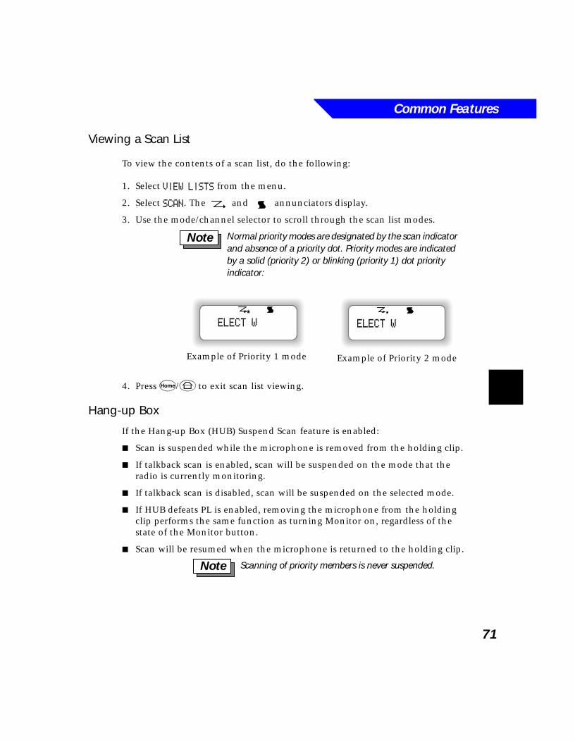
Common Features
71
Viewing a Scan List
To view the contents of a scan list, do the following:
1. Select VIEW LISTS from the menu.
2. Select SCAN. The and annunciators display.
3. Use the mode/channel selector to scroll through the scan list modes.
4. Press h/6 to exit scan list viewing.
Hang-up Box
If the Hang-up Box (HUB) Suspend Scan feature is enabled:
■ Scan is suspended while the microphone is removed from the holding clip.
■ If talkback scan is enabled, scan will be suspended on the mode that the radio is currently monitoring.
■ If talkback scan is disabled, scan will be suspended on the selected mode.
■ If HUB defeats PL is enabled, removing the microphone from the holding clip performs the same function as turning Monitor on, regardless of the state of the Monitor button.
■ Scan will be resumed when the microphone is returned to the holding clip.
Normal priority modes are designated by the scan indicator and absence of a priority dot. Priority modes are indicated by a solid (priority 2) or blinking (priority 1) dot priority indicator:
Note
ELECT W
Example of Priority 1 mode
ELECT W
Example of Priority 2 mode
Scanning of priority members is never suspended. Note
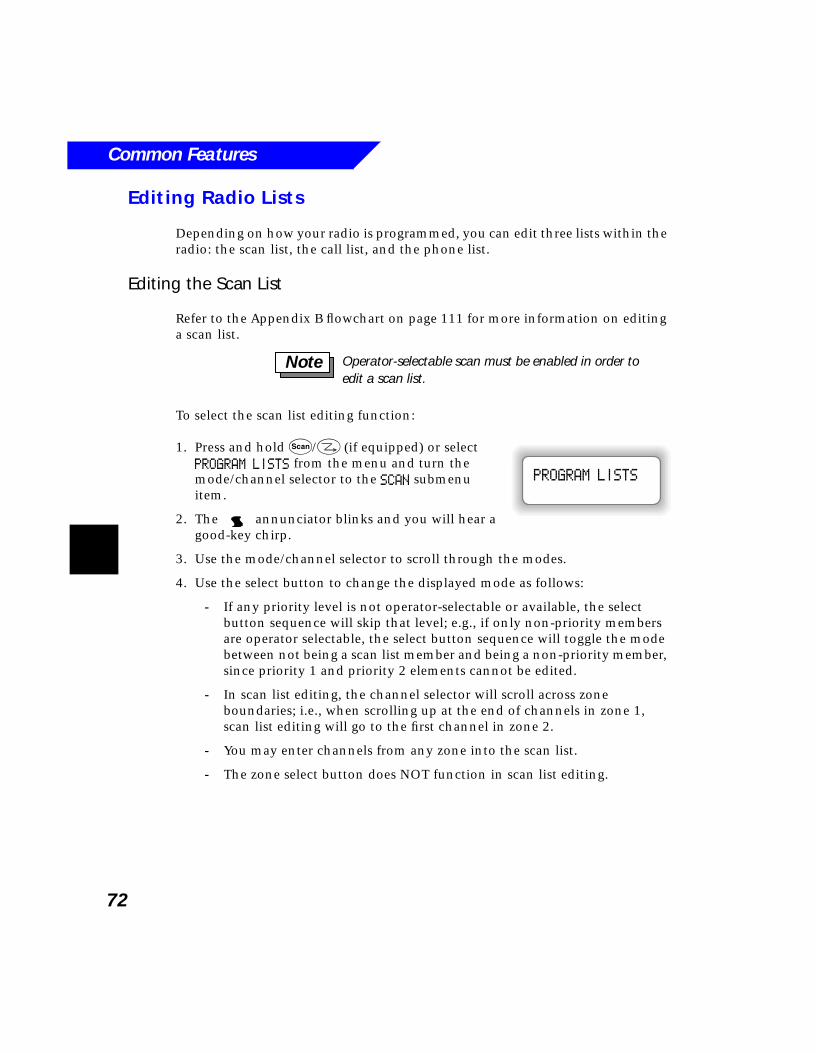
Common Features
72
Editing Radio Lists
Depending on how your radio is programmed, you can edit three lists within the radio: the scan list, the call list, and the phone list.
Editing the Scan List
Refer to the Appendix B flowchart on page 111 for more information on editing a scan list.
To select the scan list editing function:
1. Press and hold S/: (if equipped) or select PROGRAM LISTS from the menu and turn the mode/channel selector to the SCAN submenu item.
2. The annunciator blinks and you will hear a good-key chirp.
3. Use the mode/channel selector to scroll through the modes.
4. Use the select button to change the displayed mode as follows:
- If any priority level is not operator-selectable or available, the select button sequence will skip that level; e.g., if only non-priority members are operator selectable, the select button sequence will toggle the mode between not being a scan list member and being a non-priority member, since priority 1 and priority 2 elements cannot be edited.
- In scan list editing, the channel selector will scroll across zone boundaries; i.e., when scrolling up at the end of channels in zone 1, scan list editing will go to the first channel in zone 2.
- You may enter channels from any zone into the scan list.
- The zone select button does NOT function in scan list editing.
Operator-selectable scan must be enabled in order to edit a scan list.
Note
PROGRAM LISTS
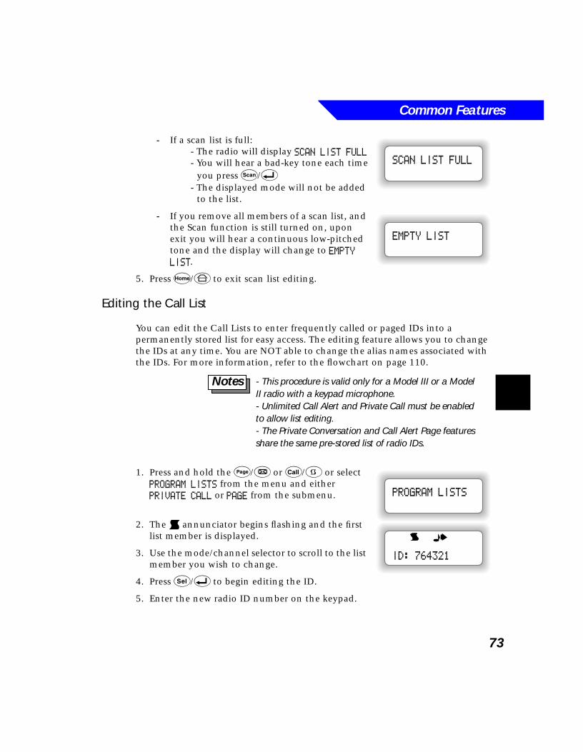
Common Features
73
- If a scan list is full:- The radio will display SCAN LIST FULL- You will hear a bad-key tone each time
you press S/8- The displayed mode will not be added
to the list.
- If you remove all members of a scan list, and the Scan function is still turned on, upon exit you will hear a continuous low-pitched tone and the display will change to EMPTY LIST.
5. Press h/6 to exit scan list editing.
Editing the Call List
You can edit the Call Lists to enter frequently called or paged IDs into a permanently stored list for easy access. The editing feature allows you to change the IDs at any time. You are NOT able to change the alias names associated with the IDs. For more information, refer to the flowchart on page 110.
1. Press and hold the P/& or C/9 or select PROGRAM LISTS from the menu and either PRIVATE CALL or PAGE from the submenu.
2. The d annunciator begins flashing and the first list member is displayed.
3. Use the mode/channel selector to scroll to the list member you wish to change.
4. Press s/8 to begin editing the ID.
5. Enter the new radio ID number on the keypad.
SCAN LIST FULL
EMPTY LIST
- This procedure is valid only for a Model III or a Model II radio with a keypad microphone. - Unlimited Call Alert and Private Call must be enabled to allow list editing. - The Private Conversation and Call Alert Page features share the same pre-stored list of radio IDs.
Notes
PROGRAM LISTS
ID: 764321
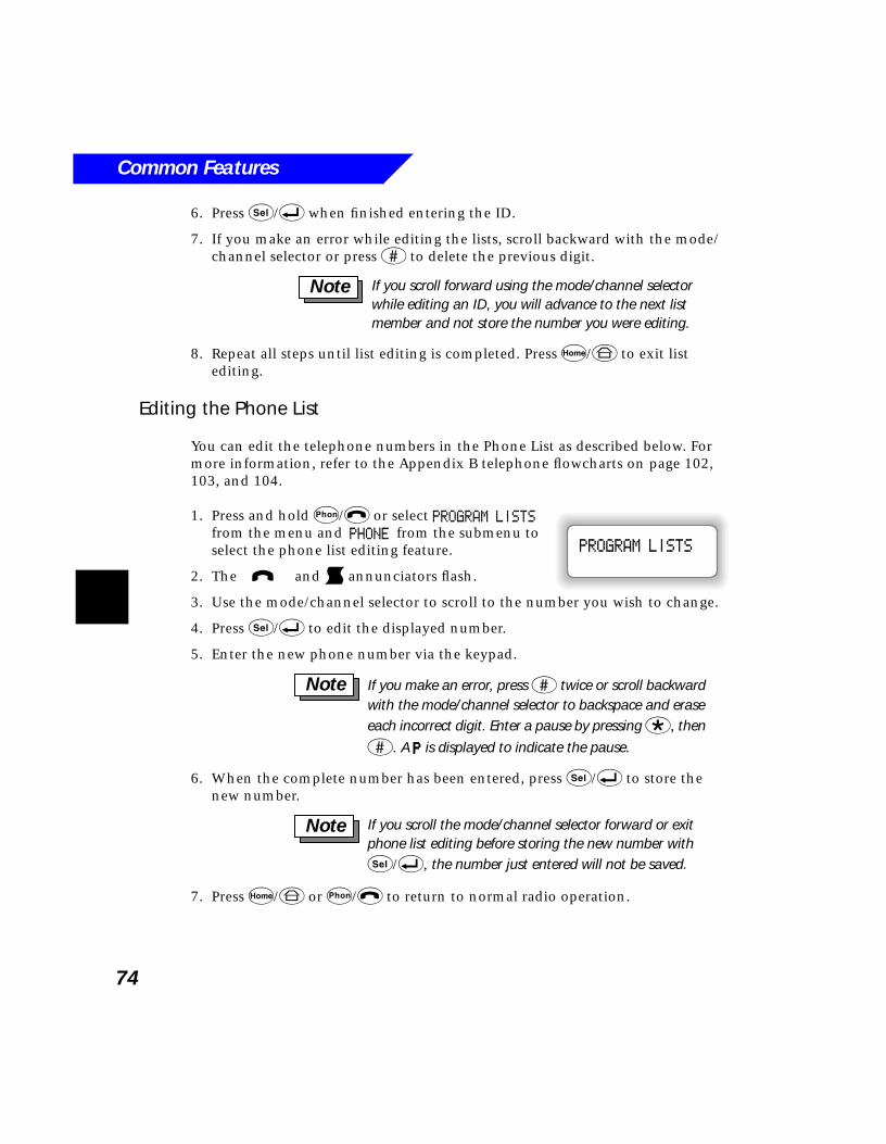
Common Features
74
6. Press s/8 when finished entering the ID.
7. If you make an error while editing the lists, scroll backward with the mode/channel selector or press # to delete the previous digit.
8. Repeat all steps until list editing is completed. Press h/6 to exit list editing.
Editing the Phone List
You can edit the telephone numbers in the Phone List as described below. For more information, refer to the Appendix B telephone flowcharts on page 102, 103, and 104.
1. Press and hold p/$ or select PROGRAM LISTS from the menu and PHONE from the submenu to select the phone list editing feature.
2. The i and d annunciators flash.
3. Use the mode/channel selector to scroll to the number you wish to change.
4. Press s/8 to edit the displayed number.
5. Enter the new phone number via the keypad.
6. When the complete number has been entered, press s/8 to store the new number.
7. Press h/6 or p/$ to return to normal radio operation.
If you scroll forward using the mode/channel selector while editing an ID, you will advance to the next list member and not store the number you were editing.
Note
PROGRAM LISTS
If you make an error, press # twice or scroll backward with the mode/channel selector to backspace and erase each incorrect digit. Enter a pause by pressing *, then
#. A PPPP is displayed to indicate the pause.
Note
If you scroll the mode/channel selector forward or exit phone list editing before storing the new number with s/8, the number just entered will not be saved.
Note
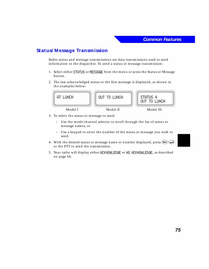
Common Features
75
Status/Message Transmission
Radio status and message transmissions are data transmissions used to send information to the dispatcher. To send a status or message transmission:
1. Select either STATUS or MESSAGE from the menu or press the Status or Message button.
2. The last acknowledged status or the first message is displayed, as shown in the examples below:
3. To select the status or message to send:
- Use the mode/channel selector to scroll through the list of status or message names, or
- Use a keypad to enter the number of the status or message you wish to send.
4. With the desired status or message name or number displayed, press s/8 or the PTT to send the transmission.
5. Your radio will display either ACKNOWLEDGE or NO ACKNOWLEDGE, as described on page 66.
STATUS 4
OUT TO LUNCH
OUT TO LUNCHAT LUNCH
Model I Model II Model III
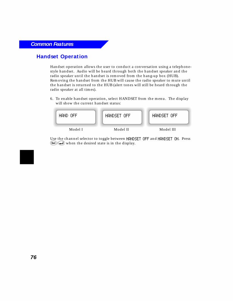
Common Features
76
Handset Operation
Handset operation allows the user to conduct a conversation using a telephone-style handset. Audio will be heard through both the handset speaker and the radio speaker until the handset is removed from the hang-up box (HUB). Removing the handset from the HUB will cause the radio speaker to mute until the handset is returned to the HUB (alert tones will still be heard through the radio speaker at all times).
6. To enable handset operation, select HANDSET from the menu. The display will show the current handset status:
Use the channel selector to toggle between HANDSET OFF and HANDSET ON. Press s/8 when the desired state is in the display.
HANDSET OFFHANDSET OFFHAND OFF
Model I Model II Model III
77
7Secure Operation
What’s In This Chapter?■ Introduction - describes the purpose of SECURENET (page 78)
■ Quick Reference - describes the Quick Reference feature of SECURENET (page 78)
■ Tones - describes the tones used in secure operation (page 79)
■ Basic SECURENET Operation - describes basic secure operation in both conventional and trunked modes (page 80)
■ SECURENET Keyloading and Key Erase - describes how to load and erase security keys (page 82)
■ Secure Operation With Other Radio Features - describes how SECURENET works with other radio features, such as Smart PTT, Emergency Operation, Telephone Operation, and Private Conversation (page 84)
Secure Operation
78
Introduction
SECURENET allows you to keep radio communications private and protected. It uses sophisticated digital encryption techniques to prevent unintended listeners from overhearing your voice traffic.
The flexibility to operate in both encrypted (secure) and clear (non-secure) modes means that SECURENET radios are easily integrated into existing systems and can remain in touch with non-secure radios in the system.
Quick Reference
To use the Quick Reference feature, simply switch your SECURENET-enhanced radio to the coded mode; there is no need to change frequencies. The secure button (3) selects clear or secure transmit operation, if the selected mode is not already strapped as secure-only or clear-only.
The secure annunciator (b) indicates the mode of operation:
b = SECURENET voice transmissionOff = clear voice transmissionb flashing = SECURENET call is being received
The messages listed in Table 6 can be displayed during secure operation.
SECURENET operation is available in Conventional, SMARTNET Type II, and SmartZone systems, but is not supported by StartSite systems, SMARTNET Type I, or 900 MHz radios.
Note
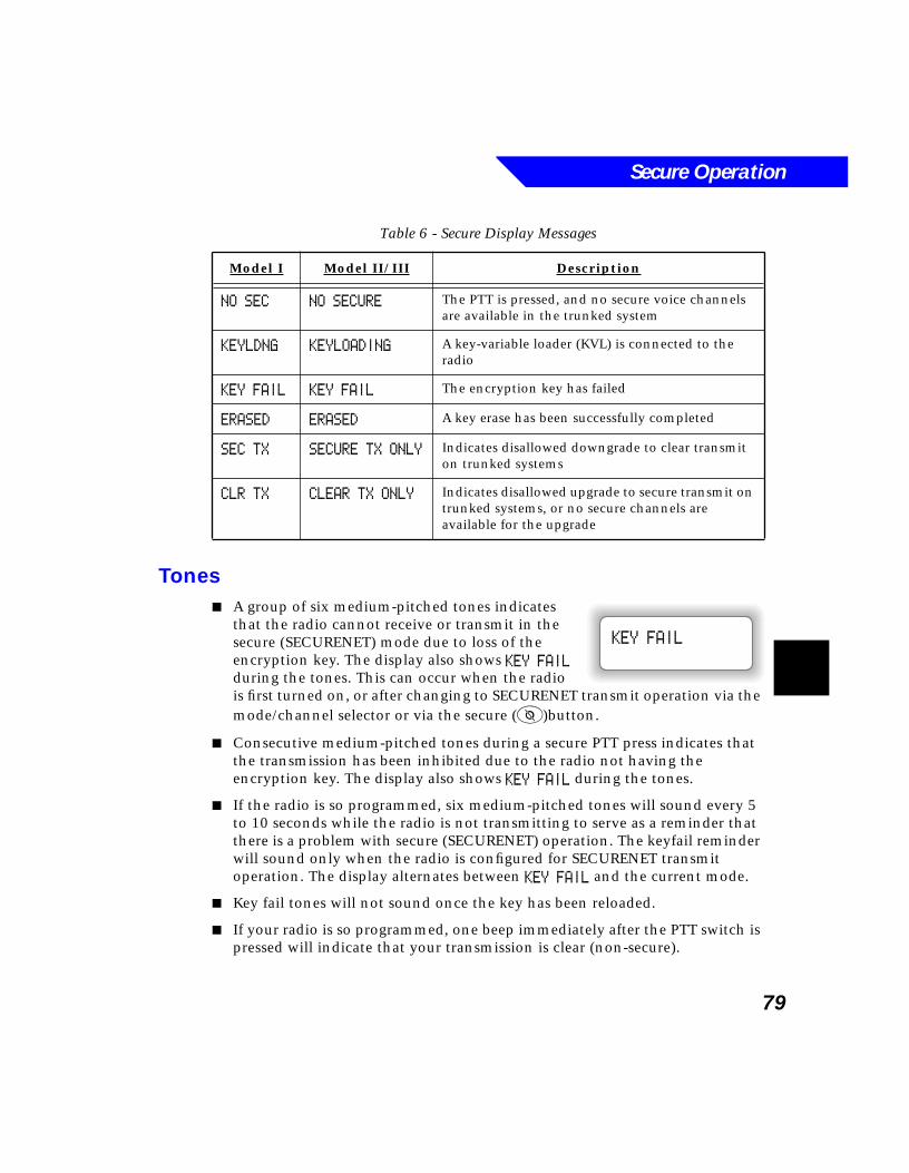
Secure Operation
79
Tones■ A group of six medium-pitched tones indicates
that the radio cannot receive or transmit in the secure (SECURENET) mode due to loss of the encryption key. The display also shows KEY FAIL during the tones. This can occur when the radio is first turned on, or after changing to SECURENET transmit operation via the mode/channel selector or via the secure (3)button.
■ Consecutive medium-pitched tones during a secure PTT press indicates that the transmission has been inhibited due to the radio not having the encryption key. The display also shows KEY FAIL during the tones.
■ If the radio is so programmed, six medium-pitched tones will sound every 5 to 10 seconds while the radio is not transmitting to serve as a reminder that there is a problem with secure (SECURENET) operation. The keyfail reminder will sound only when the radio is configured for SECURENET transmit operation. The display alternates between KEY FAIL and the current mode.
■ Key fail tones will not sound once the key has been reloaded.
■ If your radio is so programmed, one beep immediately after the PTT switch is pressed will indicate that your transmission is clear (non-secure).
Table 6 - Secure Display Messages
Model I Model II/III Description
NO SEC NO SECURE The PTT is pressed, and no secure voice channels are available in the trunked system
KEYLDNG KEYLOADING A key-variable loader (KVL) is connected to the radio
KEY FAIL KEY FAIL The encryption key has failed
ERASED ERASED A key erase has been successfully completed
SEC TX SECURE TX ONLY Indicates disallowed downgrade to clear transmit on trunked systems
CLR TX CLEAR TX ONLY Indicates disallowed upgrade to secure transmit on trunked systems, or no secure channels are available for the upgrade
KEY FAIL
Secure Operation
80
Basic SECURENET Operation
Radio On/Off
If the encryption key has failed or has not been loaded, the display will momentarily show KEY FAIL, accompanied by a six-beep keyfail tone. For SECURENET operation to function, reload the encryption key from a key-variable loader (KVL).
Monitoring
SECURENET transmissions from a radio that has the same key as the monitoring radio will be heard clearly. If the monitoring radio has no encryption key or is using a different key, the SECURENET transmission is heard as noise which is nearly indistinguishable from channel noise.
Receiving
Conventional Modes
SECURENET-equipped radios automatically determine whether a SECURENET or clear voice message is being received. The orange LED status indicator will turn on continuously when receiving a clear call, and the LED and the b icon will blink while receiving a SECURENET call.
Trunked Systems
SECURENET-equipped radios automatically determine whether a SECURENET or clear voice message is being received. The secure annunciator (b) blinks while a SECURENET call is being received.
Transmitting
Conventional Modes
If the selected mode is not strapped as either secure-only or clear-only, pressing the secure button (3) chooses secure or clear transmit operation. The secure annunciator will indicate the transmit operation:
■ b = SECURENET voice transmission
Secure Operation
81
■ Off = clear voice transmission
The radio can also be programmed so that one beep sounds immediately after the PTT switch is pressed for a clear (non-secure) transmission.
Trunked Systems
If the selected mode is not strapped as either secure-only or clear-only, pressing the secure button (3) chooses secure or clear transmit operation. The secure annunciator will indicate the transmit operation:
■ b = SECURENET voice transmission
■ Off = clear voice transmission
The radio can also be programmed so that one beep sounds immediately after the PTT switch is pressed for a clear (non-secure) transmission.
■ If the secure button (3) is pressed during a transmission (PTT active), the transmission is aborted, and an alert tone will sound until PTT is released. The transmit operation change will be effective with the next PTT press.
■ Calls on modes (talkgroups) that are programmed as neither secure-only nor clear-only can be upgraded from clear to SECURENET during the call by releasing the PTT button, pressing the secure button (3), and pressing the PTT switch again.
If the secure button is pressed during a transmission (PTT active), the transmission is aborted, and an alert tone sounds until PTT is released. The transmit operation change will be effective with the next PTT press.
Note
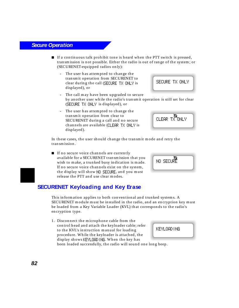
Secure Operation
82
■ If a continuous talk prohibit tone is heard when the PTT switch is pressed, transmission is not possible. Either the radio is out of range of the system; or (SECURENET-equipped radios only):
- The user has attempted to change the transmit operation from SECURENET to clear during the call (SECURE TX ONLY is displayed), or
- The call may have been upgraded to secure by another user while the radio's transmit operation is still set for clear (SECURE TX ONLY is displayed), or
- The user has attempted to change the transmit operation from clear to SECURENET during a call and no secure channels are available (CLEAR TX ONLY is displayed).
In these cases, the user should change the transmit mode and retry the transmission.
■ If no secure voice channels are currently available for a SECURENET transmission that you wish to make, a trunked busy indication is made. If no secure voice channels exist on the system, the display will show NO SECURE, and you must release the PTT and use clear modes.
SECURENET Keyloading and Key Erase
This information applies to both conventional and trunked systems. A SECURENET module must be installed in the radio, and an encryption key must be loaded from a Key Variable Loader (KVL) that corresponds to the radio's encryption type.
1. Disconnect the microphone cable from the control head and attach the keyloader cable; refer to the KVL's instruction manual for loading procedure. While the keyloader is attached, the display shows KEYLOADING. When the key has been loaded successfully, the radio will sound one long beep.
SECURE TX ONLY
CLEAR TX ONLY
NO SECURE
KEYLOADING
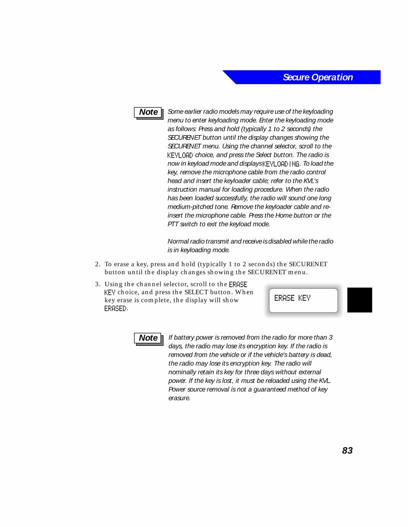
Secure Operation
83
2. To erase a key, press and hold (typically 1 to 2 seconds) the SECURENET button until the display changes showing the SECURENET menu.
3. Using the channel selector, scroll to the ERASE KEY choice, and press the SELECT button. When key erase is complete, the display will show ERASED.
Some earlier radio models may require use of the keyloading menu to enter keyloading mode. Enter the keyloading mode as follows: Press and hold (typically 1 to 2 seconds) the SECURENET button until the display changes showing the SECURENET menu. Using the channel selector, scroll to the KEYLOAD choice, and press the Select button. The radio is now in keyload mode and displays KEYLOADING. To load the key, remove the microphone cable from the radio control head and insert the keyloader cable; refer to the KVL's instruction manual for loading procedure. When the radio has been loaded successfully, the radio will sound one long medium-pitched tone. Remove the keyloader cable and re-insert the microphone cable. Press the Home button or the PTT switch to exit the keyload mode.
Normal radio transmit and receive is disabled while the radio is in keyloading mode.
Note
ERASE KEY
If battery power is removed from the radio for more than 3 days, the radio may lose its encryption key. If the radio is removed from the vehicle or if the vehicle's battery is dead, the radio may lose its encryption key. The radio will nominally retain its key for three days without external power. If the key is lost, it must be reloaded using the KVL. Power source removal is not a guaranteed method of key erasure.
Note
Secure Operation
84
Secure Operation with Other Radio Features
Smart PTT
Transmit Inhibit on Busy Mode with Wrong Squelch Code - With this feature enabled, you will be inhibited from transmitting on an active mode with an encryption key other than your own. If the encryption key is the same as yours, the transmission will not be inhibited.
Trunked Emergency Operation
When you are participating in a call, selection of secure or clear transmit operation will be controlled by the secure button (3) unless the selected mode (talkgroup) or default emergency mode has been preprogrammed as secure-only or clear-only. You will not be able to change from SECURENET operation to clear operation, or from clear to SECURENET, during a call.
Trunked Private Conversation II
When you are participating in a Trunked Private Conversation II call, selection of secure or clear transmit operation is controlled by the secure button (3). You can change from clear operation to SECURENET operation, but not from SECURENET to clear, during a call.
Trunked Enhanced Private Conversation
When you are participating in a call, selection of secure or clear transmit operation is controlled by the secure button (3). You can change from clear operation to SECURENET operation, but not from SECURENET to clear, during a call.
Trunked Telephone Operation
When you are making a call, selection of secure or clear transmit operation is controlled by the secure button (3). You can change from clear operation to SECURENET operation, or from SECURENET to clear, during a call.
The Proper Code feature must be programmed in the radio to determine if the encryption key is the same.
Note
Secure Operation
85
Dynamic Regrouping
SECURENET-equipped radios are assigned (by the dispatcher for the dynamic-regrouping mode) to be secure-/clear-selectable by the secure button.
Failsoft Operation
When you are participating in a call, selection of secure or clear transmit operation is controlled by the secure button (3) unless the selected mode (talkgroup) has been preprogrammed as secure-only or clear-only. You can change from SECURENET operation to clear operation, or from clear to SECURENET, during a call.

Secure Operation
86
87
8Operator Troubleshooting
If a FAIL ##/## message is displayed shortly after the radio is turned on, it is an indication that a serious fault exists in the radio. The radio should be serviced by a qualified Motorola service center.
If an ERROR ##/## message is displayed shortly after the radio is turned on, it is an indication that some non-critical data has changed in the radio since the radio was operated last.
If either the FAIL ##/## or ERROR ##/## message is displayed, if the display goes blank, or if the radio appears to be locked up, refer to the following suggestions. They will assist you in making proper electrical connections to your radio and troubleshooting possible operating problems.
!C a u t i o n
The cables that connect to the rear of the radio may have live voltage on some of their pins. Be careful not to short the pins to a grounded surface during installation. A blown fuse could result.
When connecting the cables to the radio, always plug in the large multi-pin accessory connector first. Otherwise, the radio may begin transmitting an emergency alarm (even if the radio is turned off).
Operator Troubleshooting
88
■ If your radio is locked up or the display shows FL 01/90 (Type I) or FAIL 01/90 (Types II and III), turn the radio off and then back on. If this does not correct the condition, check both power line fuses, then turn the radio off and carefully remove and reconnect the cables at the rear of the radio, remembering to plug in the large multi-pin connector first.
■ If radio operation is intermittent, check with others using the system for similar problems before taking the radio in for service. Similar problems would indicate a system malfunction rather than a radio failure. If symptoms persist or if your radio exhibits other problems, contact service personnel.
89
9Safety Information
What’s In This Chapter?■ General Safety Information - provides general radio safety information
(page 90)
■ Installation Safety Warning - provides safety information to consider when installing the radio (page 91)
■ Important Electromagnetic Emission Information - provides FCC-required information on electromagnetic emission (page 92)
■ Operational Safety Warning - provides safety information to consider when operating the radio (page 93)
■ Converted Mobile Equipment - provides precautions about converting mobile equipment for portable use (page 94)
■ Airbag Warning Statement - provides precautions about using mobile radios in vehicles equipped with airbags (page 94)
Safety Information
90
General Safety Information
DO NOT operate the transmitter of any radio unless all RF connectors are secure and any open connectors are properly terminated.
DO NOT operate the equipment near electrical blasting caps or in an explosive atmosphere. When you are in the vicinity of construction work, look for, and observe, signs cautioning against radio transmissions. If radio transmission is prohibited, you must not transmit until you are out of the area.
ALL equipment must be properly grounded according to Motorola installation instructions for safe operation.
ALL equipment should be serviced only by a qualified technician.
Refer to the appropriate section of the product service manual for additional pertinent safety information.
Safety Information
91
Radio Installation Safety
Installation Location
To prevent possible personal injury, consider the occupants' safety when you choose a location for the radio. Do not mount the radio overhead or on a sidewall unless you take special precautions.
If someone were to remove the radio and fail to replace it properly, road shock could bump the radio loose, and the
falling radio could, in some circumstances, cause serious injury to the driver or a passenger. In a crash, even when properly installed, the radio could break loose and become a dangerous projectile.
If you must mount the radio overhead or on a sidewall, give it the added protection of a retaining strap.
Installation Connections
The cables that connect to the rear of the radio may have live voltage on some of their pins. Be careful not to short the pins to a grounded surface during installation. A blown fuse could result.
When connecting the cables to the radio, always plug in the large multi-pin accessory connector first. Otherwise, the radio may begin transmitting an emergency alarm (even if the radio is turned off).
!W A R N I N G
!
!C a u t i o n
Safety Information
92
Important Electromagnetic Emission Information
The Federal Communications Commission (FCC), with its action in General Docket 79144, March 13, 1985, has adopted a safety standard for human exposure to radio frequency electromagnetic energy emitted by FCC regulated equipment. Motorola subscribes to this safety standard for the use of its products, and the design of your Motorola radio complies with this standard. Proper use of this radio will result in exposure levels below specified limits.
In keeping with sound installation practice and to maximize radiation efficiency, a one-quarter (1/4 ) wave length antenna should be installed at the center of the vehicle roof. If it is necessary to mount the antenna on the vehicle's trunk lid, an appropriate 3db gain antenna should be used. This installation procedure will assure that vehicle occupants will be exposed to radio frequency energy levels lower than the limits specified in the standard adopted by the FCC in General Docket 79144.
To assure that radio frequency (RF) energy exposure to bystanders external to a vehicle is lower than that recommended by FCC adopted standard, transmit with any mobile radio only when bystanders are at least two (2) feet away from a properly installed externally mounted antenna for radios with less than 50 watts of output power, or three (3) feet away for radios with 50 watts or greater power.
Control Station Operation
In the event of Control Station operation, to assure operators and bystanders are exposed to radio frequency (RF) energy levels lower than the limits specified in the FCC adopted standard, the antenna should be installed outside of any building, but in no instance shall the antenna be within two feet (less than 50 watts power output) or within three feet (50 watts or higher power output) of station operators or bystanders.
Safety Information
93
Operational Safety
For vehicles equipped with electronic anti-skid systems, see “ANTI-SKID BRAKING PRECAUTIONS” Publication, Motorola Number 68P81109E34.
For vehicles equipped with electronic ignition systems, check the service manual for warnings about the use of two-way radio equipment in the vehicle.
To prevent possible personal injury, it is mandatory that radio installations in vehicles fueled by liquefied petroleum gas conform to the following standard:
National Fire Protection Association standard NFPA 58 applies to radio installations in vehicles fueled by liquefied petroleum (LP) gas with LP gas container in the trunk or
other sealed-off space within the interior of the vehicles. This standard requires that:
■ Any space containing radio equipment shall be isolated by a seal from the space in which the LP gas container and its fittings are located.
■ Remote (outside) fitting connections shall be used.
■ The container space shall be vented to the outside.
!W A R N I N G
!
!W A R N I N G
!
Safety Information
94
Converted Mobile Equipment
CAUTION - Motorola two-way radio products which have been designed for mobile operation should not be used as battery operated portable units. In such use there is the danger that the user or other persons will be exposed to excessive radio frequency energy levels. This warning applies to all two-way radio equipment radiating in excess of seven watts RF power. Motorola strongly recommends
that any product which converts high power equipment for portable operation not be used.
Airbag Warning
An air bag inflates with great force. DO NOT place objects, including communication equipment, in the area over the air bag or in the air bag deployment area. If the communication equipment is improperly installed and the air bag inflates, this could cause serious injury.
Installation of vehicle communication equipment should be performed by a professional installer/technician
qualified in the requirements for such installations. An air bag’s size, shape, and deployment area can vary by vehicle make, model, and front compartment configuration (e.g., bench seat vs. bucket seats).
Contact the vehicle manufacturer’s corporate headquarters, if necessary, for specific air bag information for the vehicle make, model, and front compartment configuration involved in your communication equipment installation.
!C a u t i o n
!W A R N I N G
!
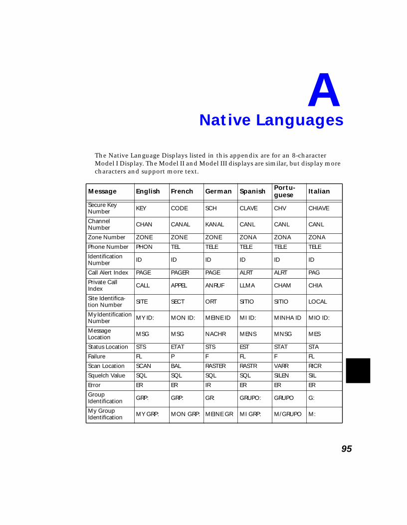
95
ANative Languages
The Native Language Displays listed in this appendix are for an 8-character Model I Display. The Model II and Model III displays are similar, but display more characters and support more text.
Message English French German Spanish Portu-guese Italian
Secure Key Number KEY CODE SCH CLAVE CHV CHIAVE
Channel Number CHAN CANAL KANAL CANL CANL CANL
Zone Number ZONE ZONE ZONE ZONA ZONA ZONA
Phone Number PHON TEL TELE TELE TELE TELE
Identification Number ID ID ID ID ID ID
Call Alert Index PAGE PAGER PAGE ALRT ALRT PAG
Private Call Index CALL APPEL ANRUF LLMA CHAM CHIA
Site Identifica-tion Number SITE SECT ORT SITIO SITIO LOCAL
My Identification Number MY ID: MON ID: MEINE ID MI ID: MINHA ID MIO ID:
Message Location MSG MSG NACHR MENS MNSG MES
Status Location STS ETAT STS EST STAT STA
Failure FL P F FL F FL
Scan Location SCAN BAL RASTER RASTR VARR RICR
Squelch Value SQL SQL SQL SQL SILEN SIL
Error ER ER IR ER ER ER
Group Identification GRP: GRP: GR: GRUPO: GRUPO G:
My Group Identification MY GRP: MON GRP: MEINE GR MI GRP: M/GRUPO M:
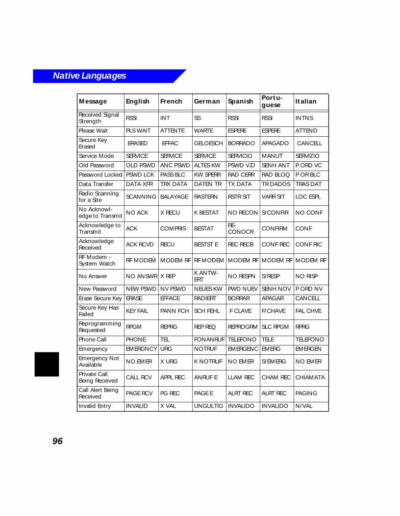
Native Languages
96
Received Signal Strength RSSI INT SS RSSI RSSI INTNS
Please Wait PLS WAIT ATTENTE WARTE ESPERE ESPERE ATTEND
Secure Key Erased ERASED EFFAC GELOESCH BORRADO APAGADO CANCELL
Service Mode SERVICE SERVICE SERVICE SERVICIO MANUT SERVIZIO
Old Password OLD PSWD ANC PSWD ALTES KW PSWD VJO SENH ANT P ORD VC
Password Locked PSWD LCK PASS BLC KW SPERR RAD CERR RAD BLOQ P OR BLC
Data Transfer DATA XFR TRX DATA DATEN TR TX DATA TR DADOS TRAS DAT
Radio Scanning for a Site SCANNING BALAYAGE RASTERN RSTR SIT VARR SIT LOC ESPL
No Acknowl-edge to Transmit NO ACK X RECU K BESTAT NO RECON S/CONFIR NO CONF
Acknowledge to Transmit ACK COMPRIS BESTAT RE-
CONOCR CONFIRM CONF
Acknowledge Received ACK RCVD RECU BESTST E REC RECB CONF REC CONF RIC
RF Modem - System Watch RF MODEM MODEM RF RF MODEM MODEM RF MODEM RF MODEM RF
No Answer NO ANSWR X REP K ANTW-ERT NO RESPN S/RESP NO RISP
New Password NEW PSWD NV PSWD NEUES KW PWD NUEV SENH NOV P ORD NV
Erase Secure Key ERASE EFFACE RADIERT BORRAR APAGAR CANCELL
Secure Key Has Failed KEY FAIL PANN FCH SCH FEHL F CLAVE F/CHAVE FAL CHVE
Reprogramming Requested RPGM REPRG REP REQ REPROGRM SLC RPGM RPRG
Phone Call PHONE TEL FONANRUF TELEFONO TELE TELEFONO
Emergency EMERGNCY URG NOTRUF EMERGENC EMERG EMERGEN
Emergency Not Available NO EMER X URG K NOTRUF NO EMER S/EMERG NO EMER
Private Call Being Received CALL RCV APPL REC ANRUF E LLAM REC CHAM REC CHIAMATA
Call Alert Being Received PAGE RCV PG REC PAGE E ALRT REC ALRT REC PAGING
Invalid Entry INVALID X VAL UNGULTIG INVALIDO INVALIDO N/VAL
Message English French German Spanish Portu-guese Italian
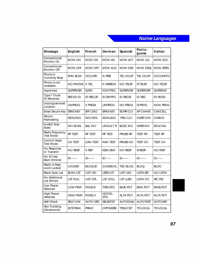
Native Languages
97
Conventional Monitor On MON ON MON ON MON AN MON ACT MON LIG MON ACC
Conventional Monitor Off MON OFF MON OFF MON AUS MON DES MON DESL MON SPEN
Phone is Currently Busy PHN BUSY OCCUPE N FREI TEL OCUP TEL OCUP OCCUPATO
Phone is not Available NO PHONE X TEL K VERBDG NO TELEF S/TELEF NO TELEF
Supervisor SUPERVSR SURV KONTROL SUPERVSR SUPERVSR SUPERVIS
Type I Trunk ID Received RECVD ID ID RECUE ID EMPFG ID RECIB ID REC ID RICEV
Unprogrammed Location UNPROG X PRGM UNPROG NO PROG S/PROG NON PROG
Erase Secure Key ERAS KEY EFF CMD ERAS KEY BORR CLV AP CHAVE CANCELL
Secure Keyloading KEYLDNG INS CMD SCHLADG PRG CLV CARR CHV CARICA
Invalid Scan State INV SCAN BAL INV UNGULT R BUSC INV VARR INV ES N/VAL
Radio Frequency Test Mode RF TEST RF TEST RF TEST PRUEB RF TEST FR TEST RF
Control Head Test Mode CH TEST CAN TEST KAN TEST PRUEB CH TEST CH TEST CH
No Response to Transmit NO RESP X REP KEIN EMF NO RESP S/RESP NO RISP
No ID Has Been Entered ID------ ID------ ID:----- ID------ ID------ ID------
Radio is Pass-word Locked LOCKED BLOQUE ZUGESCHL TEC BLOQ BLOQ BLOC
Blank Scan List BLNK LST LIST VID LEER LST LIST VAC LISTA BR NO LISTA
No Additional List Entries LST FULL LIST CPL LST VOLL LST LLEN LISTA CH RIC PIE
Low Power Selected LOW PWR PUISS B TIEFLSTG BAJA POT BAIX POT BASS POT
High Power Selected HIGH PWR PUISS H HOCHL-
STG ALTA POT ALTA POT ALTA POT
Self Check SELF CHK AUTO VER SELBSTST AUTODIAG AUTOTEST AUTOVER
Site Trunking (Smartzone) SITETRNK PRINC ORTSVERB TRNC/SIT TR LOCAL TR LOCAL
Message English French German Spanish Portu-guese Italian

Native Languages
98
Contrast CONTRAST CONTRAST CONTRAST CONTRAST CONTRAST
Horn and Lights On H/L ON AV LUM H/L AN C/L PREN B/L LIG L/SEG AC
Horn and Lights Off H/L OFF X AVLUM H/L AUS C/L APAG B/L DESL L/SEG SP
Secure Transmit Only SEC TX TX SEC SICHER S TX ENCRP TX SEG TX SIC
Clear Transmit Only CLR TX TX CLR KLARE S TX CLARA TX CLR TX CHIAR
No Secure Transmit NO SEC X SEC N SICHER NO SEGUR SEM SEG N/SICURO
Secure Failure SEC FAIL PANN SEC SICHER F SEG FALL FALH SEG FALL SIC
Secure Key Not Erased NOT ERSD X EFF N RADIER NO BORRO N/APAG NON CANC
Select Erase Secure Key ERASE KY EFF CDS SCH RAD BORR LLV AP CHAVE CANCELL
Select Secure Keyloading KEYLOAD TFR CDS SCHLADG CARG LLV CARR CHV CARICA
Transmit Attempt Denied DENIED REFUSE VERNEINT NEGADO NEGADO NEGATO
Site Unlocked UNLOCKED DEBLOQUE K ORTUNG NO CERAD SIT DSBL SBLO
Site Locked LOCKED BLOQUE ORTUNG CERRADO SIT BLOQ BLOC
Failsoft Trunked Operation FAILSOFT PANN PSG KON VERL FAILSOFT FALHA SV FAL LEGG
Password En-tered Too Short TOO SHRT TROP CRT ZU KURZ CORTO SENH CRT P OR COR
Talkaround Mode DIRECT DIRECT DIREKT MOD DIR DIRETO MOD DIR
Repeater Mode REPEATER REPETN VERSTARK MOD REP REPETIDO MOD RIP
Keypad Tones Off TONE OFF X SON TON AUS TONO APA TOM DESL TONO DIS
Keypad Tones On TONE ON SON TON AN TONO PRE TOM LIG TONO ATT
Scanning Off SCAN OFF X BAL RAST AUS RSTR APA VARR DSL RIC DIS
Scanning On SCAN ON BAL RAST AN RSTR PRE VARR LIG RIC ATT
Transmit Inhibit Off TXIN OFF X TXBLOC TXIN AUS TXIN APA TX DSIN TXIN DIS
Message English French German Spanish Portu-guese Italian
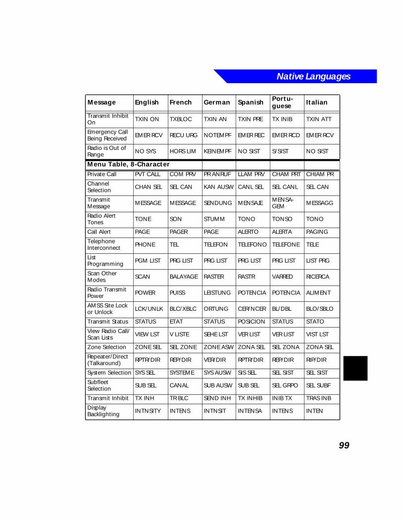
Native Languages
99
Transmit Inhibit On TXIN ON TXBLOC TXIN AN TXIN PRE TX INIB TXIN ATT
Emergency Call Being Received EMER RCV RECU URG NOTEMPF EMER REC EMER RCD EMER RCV
Radio is Out of Range NO SYS HORS LIM KEINEMPF NO SIST S/SIST NO SIST
Menu Table, 8-CharacterPrivate Call PVT CALL COM PRV PR ANRUF LLAM PRV CHAM PRT CHIAM PR
Channel Selection CHAN SEL SEL CAN KAN AUSW CANL SEL SEL CANL SEL CAN
Transmit Message MESSAGE MESSAGE SENDUNG MENSAJE MENSA-
GEM MESSAGG
Radio Alert Tones TONE SON STUMM TONO TONSO TONO
Call Alert PAGE PAGER PAGE ALERTO ALERTA PAGING
Telephone Interconnect PHONE TEL TELEFON TELEFONO TELEFONE TELE
List Programming PGM LIST PRG LIST PRG LIST PRG LIST PRG LIST LIST PRG
Scan Other Modes SCAN BALAYAGE RASTER RASTR VARRED RICERCA
Radio Transmit Power POWER PUISS LEISTUNG POTENCIA POTENCIA ALIMENT
AMSS Site Lock or Unlock LCK/UNLK BLC/XBLC ORTUNG CER/NCER BL/DBL BLO/SBLO
Transmit Status STATUS ETAT STATUS POSICION STATUS STATO
View Radio Call/Scan Lists VIEW LST V LISTE SEHE LST VER LIST VER LIST VIST LST
Zone Selection ZONE SEL SEL ZONE ZONE ASW ZONA SEL SEL ZONA ZONA SEL
Repeater/Direct (Talkaround) RPTR/DIR REP/DIR VER/DIR RPTR/DIR REP/DIR RIP/DIR
System Selection SYS SEL SYSTEME SYS AUSW SIS SEL SEL SIST SEL SIST
Subfleet Selection SUB SEL CANAL SUB AUSW SUB SEL SEL GRPO SEL SUBF
Transmit Inhibit TX INH TR BLC SEND INH TX INHIB INIB TX TRAS INB
Display Backlighting INTNSITY INTENS INTNSIT INTENSA INTENS INTEN
Message English French German Spanish Portu-guese Italian

Native Languages
100
101
BOperational Flowcharts
What’s In This Chapter?■ B1.1 - PHONE: Direct Entry - describes in a flowchart how to directly
enter a telephone number (page 102)
■ B1.2 - PHONE: List Scrolling - describes in a flowchart how to scroll through your radio’s phone list (page 103)
■ B1.3 - PHONE: List Editing - describes in a flowchart how to edit your radio’s phone list (page 104)
■ B2.1 - MDC SELECTIVE CALL/PAGE: Direct Entry - describes in a flowchart how to directly enter a selective call/page number (page 105)
■ B2.2 - MDC SELECTIVE CALL/PAGE: List Scrolling - describes in a flowchart how to scroll through your radio’s selective call/page list (page 106)
■ B2.3 - MDC SELECTIVE CALL/PAGE: List Editing - describes in a flowchart how to edit your radio’s selective call/paging list (page 107)
■ B3.1 - TRUNKING PRIVATE CALL/PAGE: Direct Entry - describes in a flowchart how to directly enter a private call/page number (page 108)
■ B3.2 - TRUNKING PRIVATE CALL/PAGE: List Scrolling - describes in a flowchart how to scroll through your radio’s call list (page 109)
■ B3.3 - TRUNKING PRIVATE CALL/PAGE: List Editing - describes in a flowchart how to edit your radio’s call list (page 110)
■ B4.1 - SCAN: List Editing - describes in a flowchart how to edit your radio’s scan list (page 111)
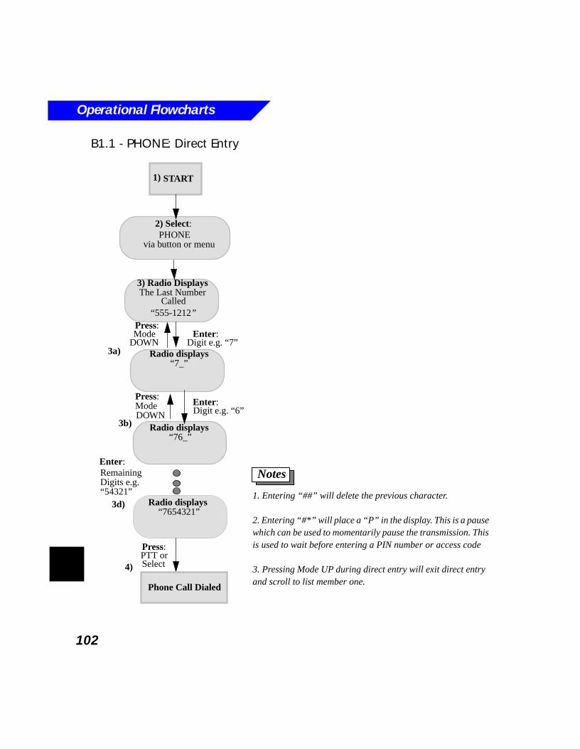
Operational Flowcharts
102
B1.1 - PHONE: Direct Entry
3) Radio Displays
Radio displays
2) Select: PHONE
1. Entering “##” will delete the previous character.
2. Entering “#*” will place a “P” in the display. This is a pause which can be used to momentarily pause the transmission. This is used to wait before entering a PIN number or access code
3. Pressing Mode UP during direct entry will exit direct entry and scroll to list member one.
Notes
START
The Last Number
“7_”
Called
via button or menu
3a)
3b)
1)
Radio displays “76_”
Radio displays “7654321”
“555-1212”
Press:ModeDOWN
Enter:Digit e.g. “6”
3d)
Enter:RemainingDigits e.g.
Press:PTT or
Phone Call Dialed
4)
Press:Mode
DOWNEnter:
Digit e.g. “7”
“54321”
Select
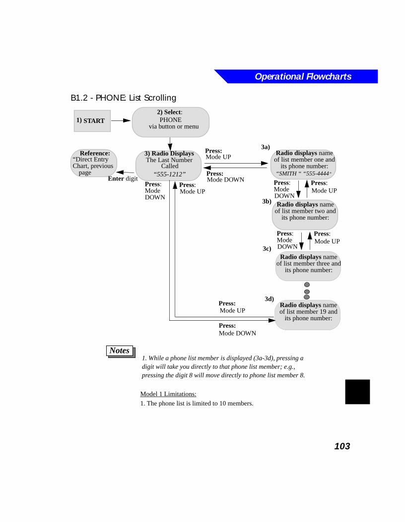
Operational Flowcharts
103
B1.2 - PHONE: List Scrolling
3) Radio Displays Radio displays name
2) Select: PHONE
1. While a phone list member is displayed (3a-3d), pressing a digit will take you directly to that phone list member; e.g., pressing the digit 8 will move directly to phone list member 8.
Notes
START
The Last Number of list member one andits phone number:Called
Model 1 Limitations:
1. The phone list is limited to 10 members.
via button or menu
3a)
3b)
3c)
1)
“SMITH “ “555-4444”
Radio displays nameof list member two and
its phone number:
Radio displays nameof list member three and
its phone number:
Radio displays nameof list member 19 and
its phone number:
Press:Mode DOWN
Press:Mode UP
Enter digit
“Direct EntryReference:
Chart, previous
page “555-1212”
Press:Mode UP
Press:ModeDOWN
Press:Mode DOWN
Press:Mode UP
Press:ModeDOWN
Press:Mode UP
Press:ModeDOWN
Press:Mode UP
3d)
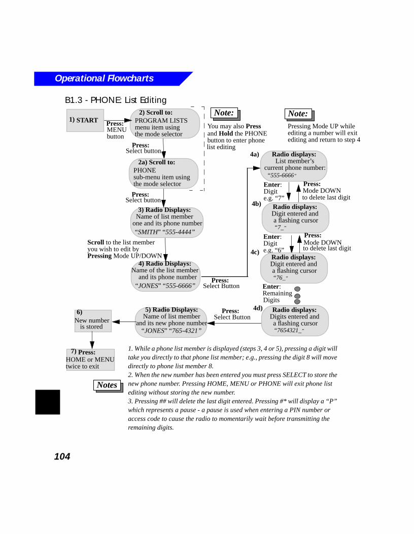
Operational Flowcharts
104
B1.3 - PHONE: List Editing
3) Radio Displays:
Radio displays:
2) Scroll to:
1. While a phone list member is displayed (steps 3, 4 or 5), pressing a digit will take you directly to that phone list member; e.g., pressing the digit 8 will move directly to phone list member 8.2. When the new number has been entered you must press SELECT to store the new phone number. Pressing HOME, MENU or PHONE will exit phone list editing without storing the new number.3. Pressing ## will delete the last digit entered. Pressing #* will display a “P” which represents a pause - a pause is used when entering a PIN number or access code to cause the radio to momentarily wait before transmitting the remaining digits.
Notes
START
Name of list member
List member’scurrent phone number:
4a)
4b)
4c)
1)
“555-6666”
Radio displays: Digit entered and a flashing cursor
“SMITH” “555-4444”
Enter:
4d)
You may also Press and Hold the PHONE button to enter phone
one and its phone number
Digite.g. “7”
“7_”
Enter:Digite.g. “6”
Radio displays: Digit entered and a flashing cursor “76_”
Enter:RemainingDigits
Radio displays: Digits entered and a flashing cursor “7654321_”
Press:Select Button
5) Radio Displays:Name of list member
“SMITH” “555-4444”
and its new phone number“JONES” “765-4321”
Press:Mode DOWN to delete last digit
Press:
Note:
4) Radio Displays:Name of the list member
and its phone number“JONES” “555-6666”
Scroll to the list member
Press:Select Button
you wish to edit by Pressing Mode UP/DOWN
6)
is stored New number
Press:MENU button
PROGRAM LISTSmenu item using
2a) Scroll to:
PHONE sub-menu item using
Press:Select button
list editing
7)HOME or MENU
Press:
twice to exit
Mode DOWN to delete last digit
the mode selector
the mode selector
Press:Select button
Note:Pressing Mode UP while editing a number will exitediting and return to step 4
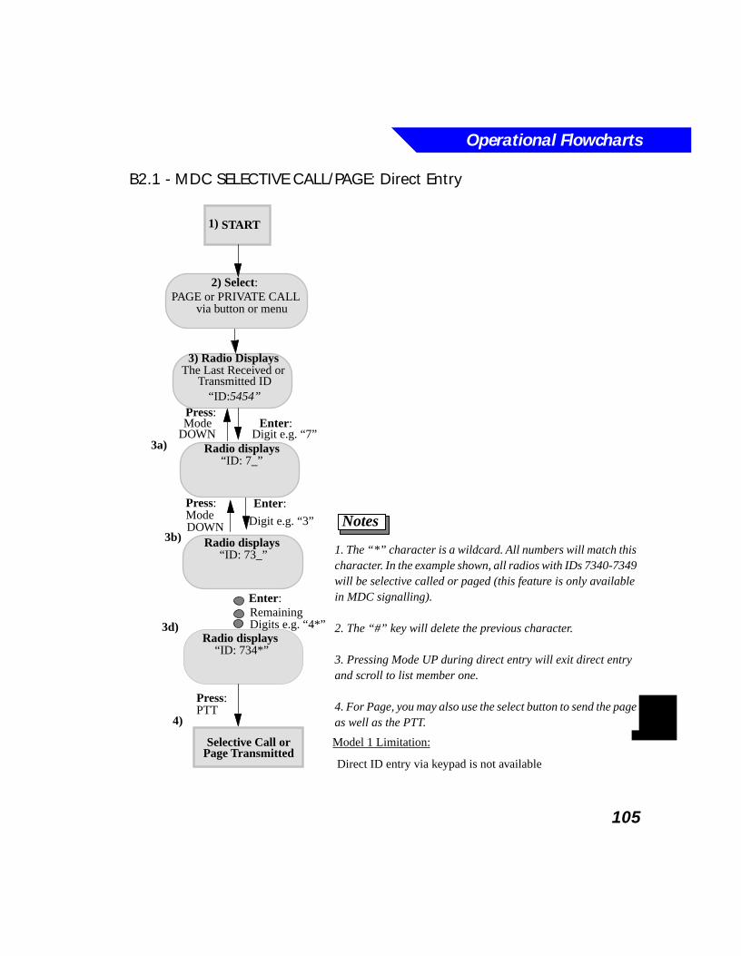
Operational Flowcharts
105
B2.1 - MDC SELECTIVE CALL/PAGE: Direct Entry
3) Radio Displays
Radio displays
2) Select: PAGE or PRIVATE CALL
1. The “*” character is a wildcard. All numbers will match this character. In the example shown, all radios with IDs 7340-7349 will be selective called or paged (this feature is only available in MDC signalling).
2. The “#” key will delete the previous character.
3. Pressing Mode UP during direct entry will exit direct entry and scroll to list member one.
4. For Page, you may also use the select button to send the page as well as the PTT.
Notes
START
The Last Received or
“ID: 7_”
Transmitted ID
Model 1 Limitation:
Direct ID entry via keypad is not available
via button or menu
3a)
3b)
1)
Radio displays “ID: 73_”
Radio displays “ID: 734*”
“ID:5454”
Press:ModeDOWN
Enter:
Digit e.g. “3”
3d)
Enter:RemainingDigits e.g. “4*”
Press:PTT
Selective Call or
4)
Page Transmitted
Press:Mode
DOWNEnter:
Digit e.g. “7”
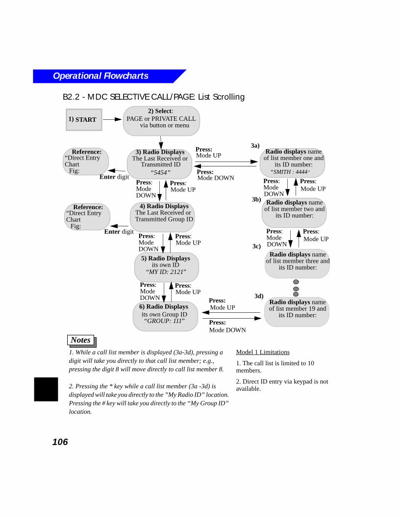
Operational Flowcharts
106
B2.2 - MDC SELECTIVE CALL/PAGE: List Scrolling
5) Radio Displays
3) Radio Displays Radio displays name
2) Select: PAGE or PRIVATE CALL
4) Radio Displays
6) Radio Displays its own Group ID
1. While a call list member is displayed (3a-3d), pressing a digit will take you directly to that call list member; e.g., pressing the digit 8 will move directly to call list member 8.
2. Pressing the * key while a call list member (3a -3d) is displayed will take you directly to the ”My Radio ID” location. Pressing the # key will take you directly to the “My Group ID” location.
Notes
START
The Last Received or
The Last Received or Transmitted Group ID
of list member one andits ID number:
its own ID
Transmitted ID
via button or menu
3a)
3b)
3c)
1)
“SMITH : 4444”
Radio displays nameof list member two and
its ID number:
Radio displays nameof list member three and
its ID number:
Radio displays nameof list member 19 and
its ID number:
Press:Mode DOWN
Press:Mode UP
Enter digit
“Direct EntryReference:
Chart
Fig: “5454”
“Direct EntryReference:
Chart Fig:
Enter digit
Press:Mode UP
Press:ModeDOWN
“MY ID: 2121”
Press:ModeDOWN
Press:ModeDOWN
Press:Mode UP
Press:Mode UP
“GROUP: 111” Press:Mode DOWN
Press:Mode UP
Press:ModeDOWN
Press:Mode UP
Press:ModeDOWN
Press:Mode UP
3d)
Model 1 Limitations
1. The call list is limited to 10 members.
2. Direct ID entry via keypad is not available.
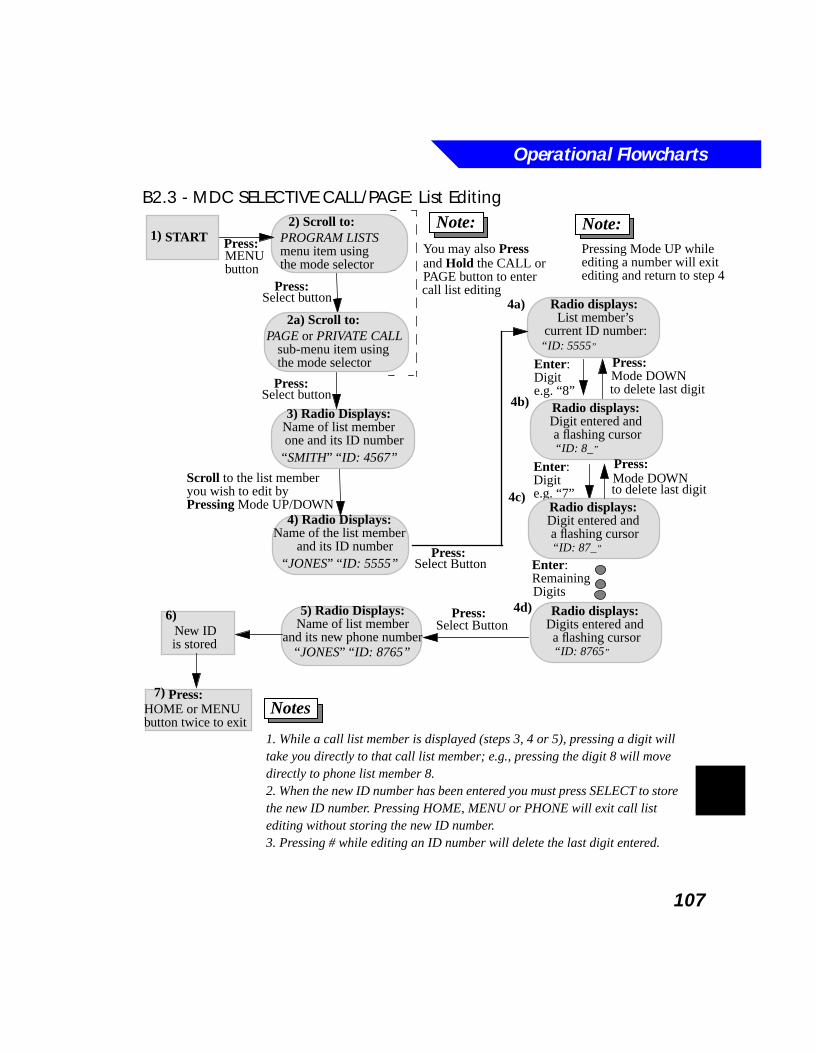
Operational Flowcharts
107
B2.3 - MDC SELECTIVE CALL/PAGE: List Editing
3) Radio Displays:
Radio displays:
2) Scroll to:
1. While a call list member is displayed (steps 3, 4 or 5), pressing a digit will take you directly to that call list member; e.g., pressing the digit 8 will move directly to phone list member 8.2. When the new ID number has been entered you must press SELECT to store the new ID number. Pressing HOME, MENU or PHONE will exit call list editing without storing the new ID number.3. Pressing # while editing an ID number will delete the last digit entered.
Notes
START
Name of list member
List member’scurrent ID number:
4a)
4b)
4c)
1)
“ID: 5555”
Radio displays: Digit entered and a flashing cursor
“SMITH” “555-4444”
Enter:
4d)
You may also Press and Hold the CALL orPAGE button to enter
one and its ID number
Digite.g. “8”
“ID: 8_”
Enter:Digite.g. “7”
Radio displays: Digit entered and a flashing cursor “ID: 87_”
Enter:RemainingDigits
Radio displays: Digits entered and a flashing cursor “ID: 8765”
Press:Select Button
5) Radio Displays:Name of list member
“SMITH” “ID: 4567”
and its new phone number“JONES” “ID: 8765”
Press:Mode DOWN to delete last digit
Press:
Note:
4) Radio Displays:Name of the list member
and its ID number“JONES” “ID: 5555”
Scroll to the list member
Press:Select Button
you wish to edit by Pressing Mode UP/DOWN
6)
is stored New ID
Press:MENU button
PROGRAM LISTSmenu item using
2a) Scroll to:
PAGE or PRIVATE CALLsub-menu item using
Press:Select button
call list editing
7)HOME or MENU
Press:
button twice to exit
Mode DOWN to delete last digit
the mode selector
the mode selector
Press:Select button
Note:Pressing Mode UP while editing a number will exitediting and return to step 4
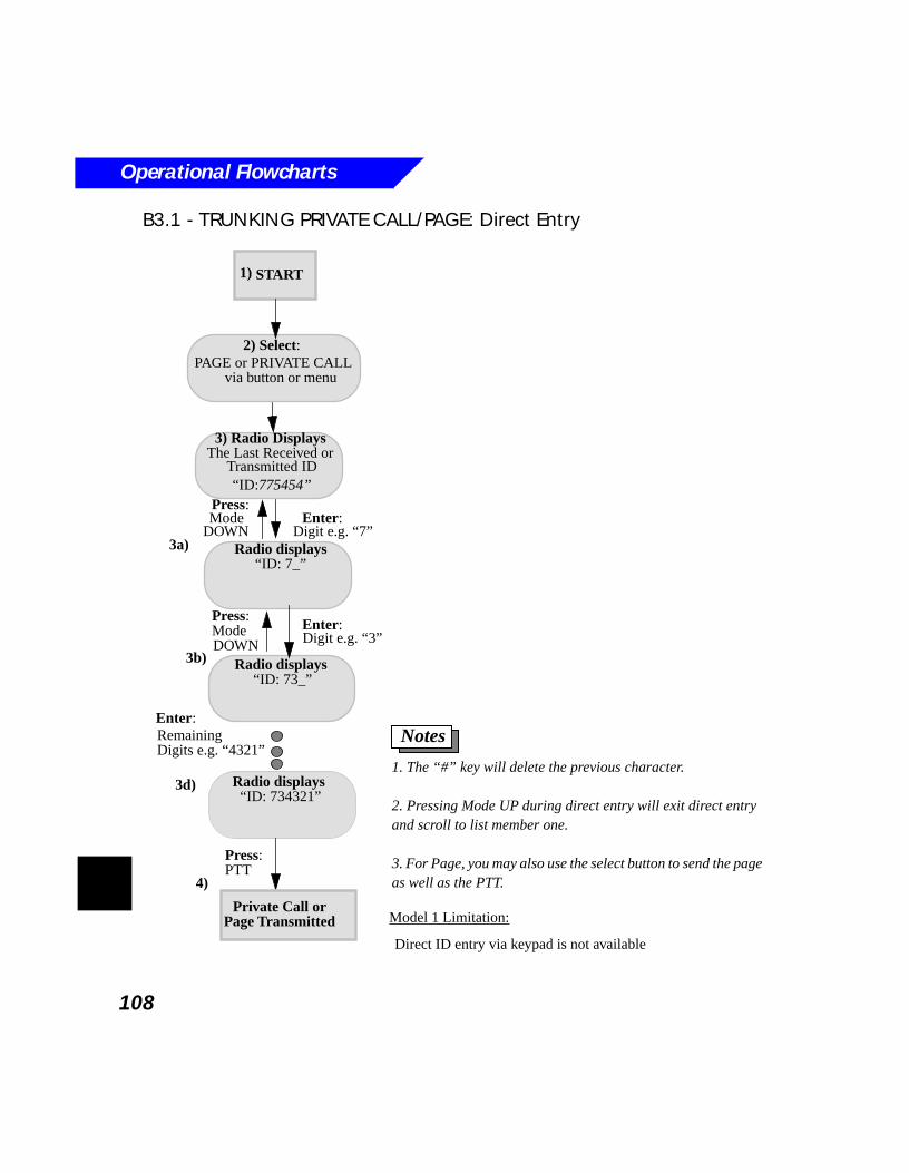
Operational Flowcharts
108
B3.1 - TRUNKING PRIVATE CALL/PAGE: Direct Entry
3) Radio Displays
Radio displays
2) Select: PAGE or PRIVATE CALL
1. The “#” key will delete the previous character.
2. Pressing Mode UP during direct entry will exit direct entry and scroll to list member one.
3. For Page, you may also use the select button to send the page as well as the PTT.
Notes
START
The Last Received or
“ID: 7_”
Transmitted ID
Model 1 Limitation:
Direct ID entry via keypad is not available
via button or menu
3a)
3b)
1)
Radio displays “ID: 73_”
Radio displays “ID: 734321”
“ID:775454”
Press:ModeDOWN
Enter:Digit e.g. “3”
3d)
Enter:RemainingDigits e.g. “4321”
Press:PTT
Private Call or
4)
Page Transmitted
Press:Mode
DOWNEnter:
Digit e.g. “7”
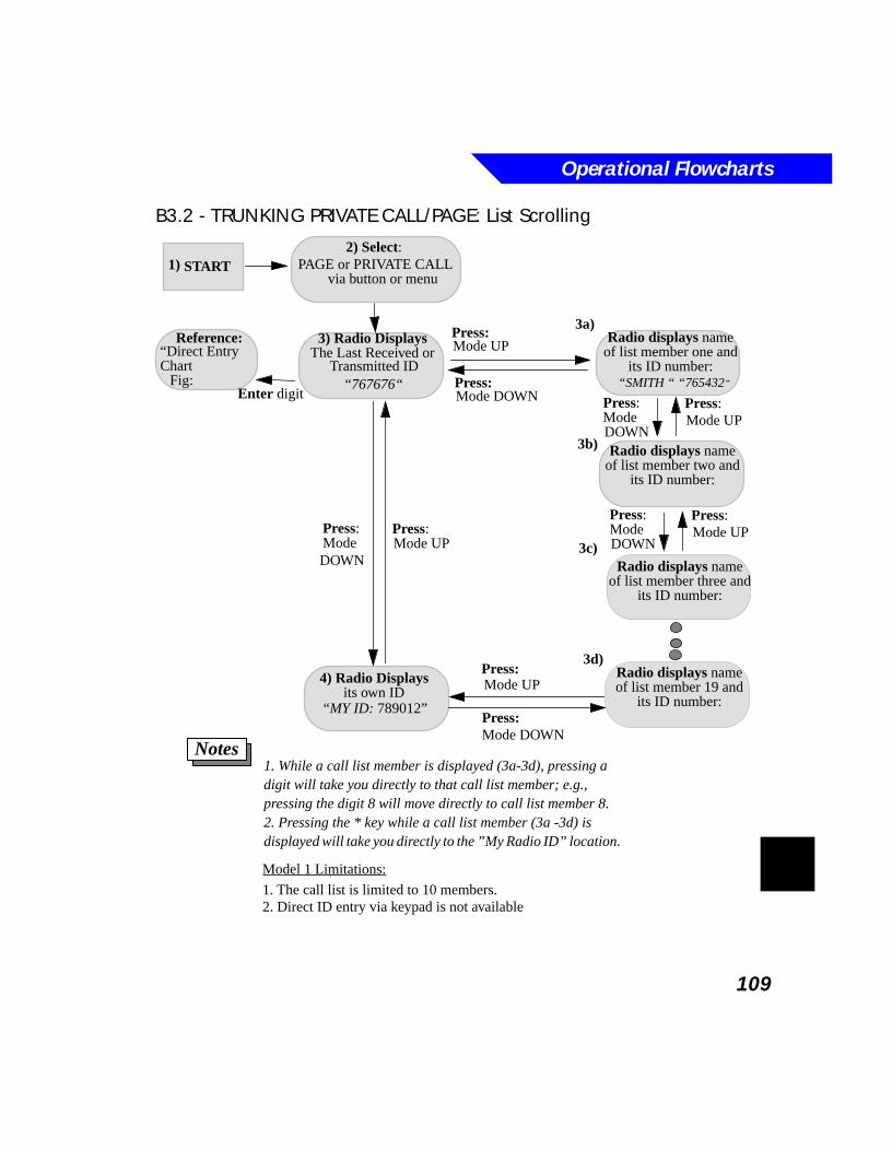
Operational Flowcharts
109
B3.2 - TRUNKING PRIVATE CALL/PAGE: List Scrolling
4) Radio Displays
3) Radio Displays Radio displays name
2) Select: PAGE or PRIVATE CALL
1. While a call list member is displayed (3a-3d), pressing a digit will take you directly to that call list member; e.g., pressing the digit 8 will move directly to call list member 8.2. Pressing the * key while a call list member (3a -3d) is displayed will take you directly to the ”My Radio ID” location.
Notes
START
The Last Received or of list member one andits ID number:
its own ID
Transmitted ID
Model 1 Limitations:
1. The call list is limited to 10 members.2. Direct ID entry via keypad is not available
via button or menu
3a)
3b)
3c)
1)
“SMITH “ “765432”
Radio displays nameof list member two and
its ID number:
Radio displays nameof list member three and
its ID number:
Radio displays nameof list member 19 and
its ID number:
Press:Mode DOWN
Press:Mode UP
Enter digit
“Direct EntryReference:
Chart
Fig: “767676“
Press:Mode UP
Press:Mode
“MY ID: 789012”Press:Mode DOWN
Press:Mode UP
Press:ModeDOWN
Press:Mode UP
Press:ModeDOWN
Press:Mode UP
3d)
DOWN
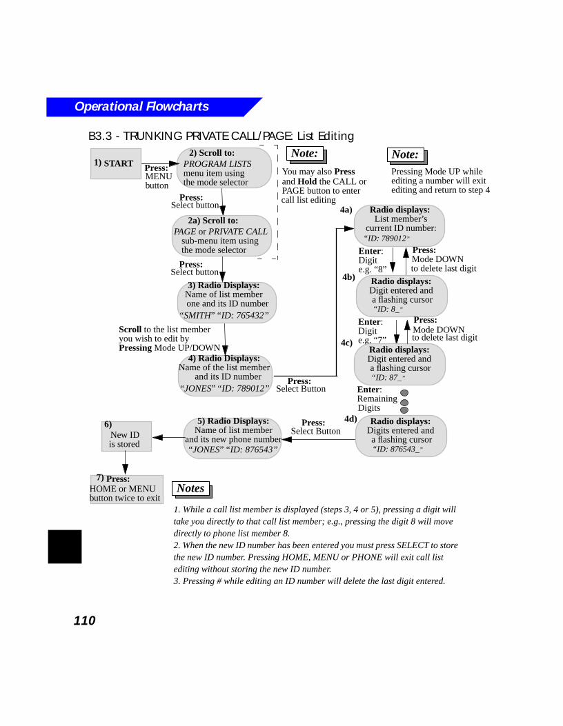
Operational Flowcharts
110
B3.3 - TRUNKING PRIVATE CALL/PAGE: List Editing
3) Radio Displays:
Radio displays:
2) Scroll to:
1. While a call list member is displayed (steps 3, 4 or 5), pressing a digit will take you directly to that call list member; e.g., pressing the digit 8 will move directly to phone list member 8.2. When the new ID number has been entered you must press SELECT to store the new ID number. Pressing HOME, MENU or PHONE will exit call list editing without storing the new ID number.3. Pressing # while editing an ID number will delete the last digit entered.
Notes
START
Name of list member
List member’scurrent ID number:
4a)
4b)
4c)
1)
“ID: 789012”
Radio displays: Digit entered and a flashing cursor
“SMITH” “555-4444”
Enter:
4d)
You may also Press and Hold the CALL orPAGE button to enter
one and its ID number
Digite.g. “8”
“ID: 8_”
Enter:Digite.g. “7”
Radio displays: Digit entered and a flashing cursor “ID: 87_”
Enter:RemainingDigits
Radio displays: Digits entered and a flashing cursor “ID: 876543_”
Press:Select Button
5) Radio Displays:Name of list member
“SMITH” “ID: 765432”
and its new phone number“JONES” “ID: 876543”
Press:Mode DOWN to delete last digit
Press:
Note:
4) Radio Displays:Name of the list member
and its ID number“JONES” “ID: 789012”
Scroll to the list member
Press:Select Button
you wish to edit by Pressing Mode UP/DOWN
6)
is stored New ID
Press:MENU button
PROGRAM LISTSmenu item using
2a) Scroll to:
PAGE or PRIVATE CALLsub-menu item using
Press:Select button
call list editing
7)HOME or MENU
Press:
button twice to exit
Mode DOWN to delete last digit
the mode selector
the mode selector
Press:Select button
Note:Pressing Mode UP while editing a number will exitediting and return to step 4
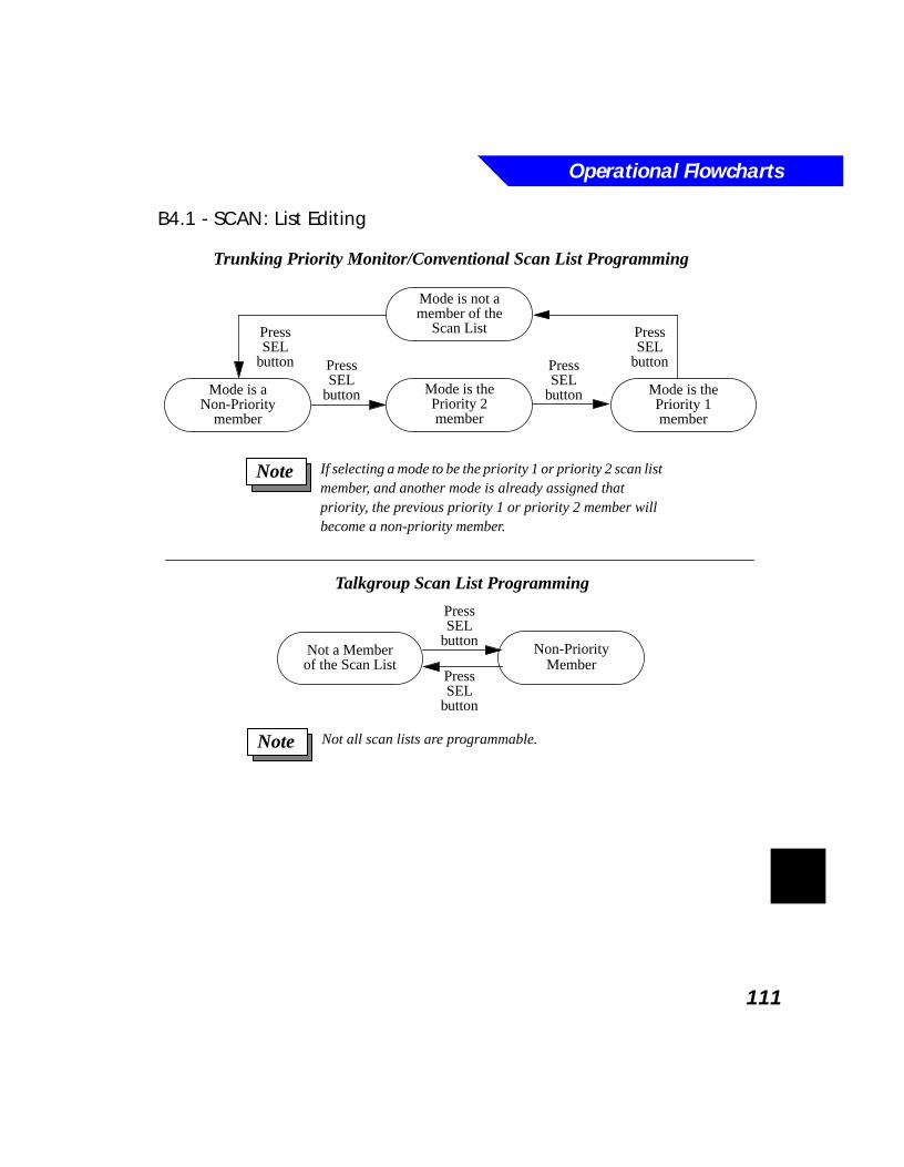
Operational Flowcharts
111
B4.1 - SCAN: List Editing
Trunking Priority Monitor/Conventional Scan List Programming
Mode is the Mode is theMode is a
Press
Non-Priority
Mode is not a
Non-PriorityMember
Not a Memberof the Scan List
Not all scan lists are programmable.Note
If selecting a mode to be the priority 1 or priority 2 scan list member, and another mode is already assigned that priority, the previous priority 1 or priority 2 member will become a non-priority member.
Note
Talkgroup Scan List Programming
member of theScan List
member
SELbutton
PressSEL
button
PressSEL
button
PressSEL
button
Priority 2member
Priority 1member
PressSEL
button
PressSEL
button

Operational Flowcharts
112
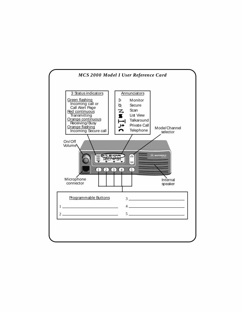
2
3
4
5
1
Microphoneconnector
a
b
d
jei
MonitorSecureScanList ViewTalkaroundPrivate CallTelephone
Green flashingIncoming call orCall Alert Page
Red continuous
Orange continuousReceiving/Busy
Transmitting
Orange flashingIncoming Secure call
Programmable Buttons
Annunciators3 Status indicators
MCS 2000 Model I User Reference Card
On/OffVolume
MCS 2000
Menu Sel
ABC74FGHbbbbccccddddjjjjeeeeggggiiii
Mode/Channelselector
1 2 3 4 5
Internalspeaker

114
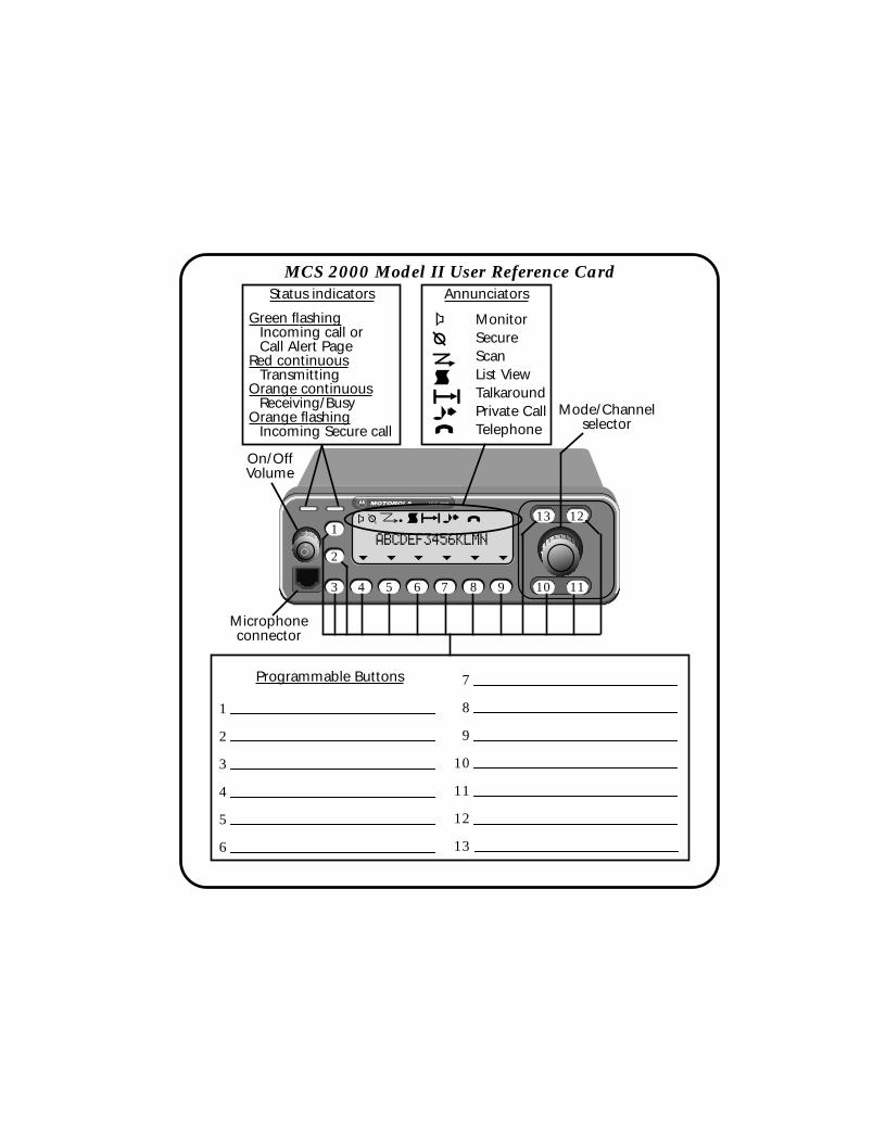
Scan Call
Zone
Page
HomeOpt
SelMenu
MCS 2000
H/L Phon
2
3
4
5
6
7
8
9
10
11
12
13
1
Microphoneconnector
a
d
jei
MonitorSecureScanList ViewTalkaroundPrivate CallTelephone
Green flashingIncoming call orCall Alert Page
Red continuous
Orange continuousReceiving/Busy
Transmitting
Orange flashingIncoming Secure call
Programmable Buttons
AnnunciatorsStatus indicatorsMCS 2000 Model II User Reference Card
On/OffVolume
1
2
3 4 5 6 7 8 9 10 11
1213
Mode/Channelselector
ABCDEF3456KLMN
a bc djei

116
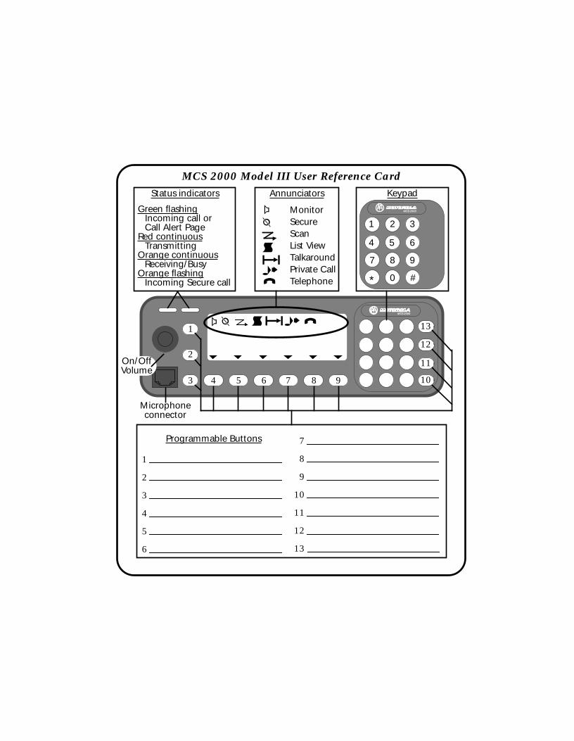
2
3
4
5
6
7
8
9
10
11
12
13
1
MCS 2000
a b djei1
2
3 4 5 6 7 8 9 10
11
12
13
Microphoneconnector
a
b
d
jei
MonitorSecureScanList ViewTalkaroundPrivate CallTelephone
Green flashingIncoming call orCall Alert Page
Red continuous
Orange continuousReceiving/Busy
Transmitting
Orange flashingIncoming Secure call
Programmable Buttons
AnnunciatorsStatus indicators
MCS 2000
Keypad
1 2 3
4 5 6
7 8 9
0 #*
MCS 2000 Model III User Reference Card
On/OffVolume

118
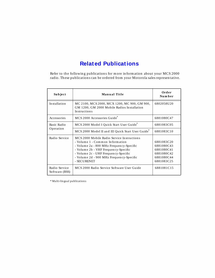
Related Publications
Refer to the following publications for more information about your MCS 2000 radio. These publications can be ordered from your Motorola sales representative.
* Multi-lingual publications
Subject Manual Title Order Number
Installation MC 2100, MCS 2000, MCX 1200, MC 900, GM 900, GM 1200, GM 2000 Mobile Radios Installation Instructions
6802058U20
Accessories MCS 2000 Accessories Guide* 6881080C47
Basic Radio Operation
MCS 2000 Model I Quick Start User Guide* 6881083C05
MCS 2000 Model II and III Quick Start User Guide* 6881083C10
Radio Service MCS 2000 Mobile Radio Service Instructions- Volume 1 - Common Information- Volume 2a - 800 MHz Frequency-Specific- Volume 2b - VHF Frequency-Specific- Volume 2c - UHF Frequency-Specific- Volume 2d - 900 MHz Frequency-Specific- SECURENET
6881083C206881080C436881080C416881080C426881080C446881083C25
Radio Service Software (RSS)
MCS 2000 Radio Service Software User Guide 6881081C15