Embed Size (px)
Citation preview

MCR1900Media Converter19-Slot Chassis
Installation Guide
Part #5500304-11

Copyright Statement
This document must not be reproduced in any way whatsoever, either printed or electronically, without the consent of:
Perle Systems Limited 60 Renfrew Drive Markham, ON Canada L3R 0E1
Perle reserves the right to make changes without further notice, to any products to improve reliability, function, or design.
Perle, the Perle logo, and MCR1900 are trademarks of Perle Systems Limited.
Perle Systems Limited, 2011.
FCC
This product has been found to comply with the limits for a Class A digital device, pursuant to Part 15 of the FCC rules. These limits are designed to provide reasonable protection against harmful interference when the equipment is operated in a commercial environment. This equipment generates, uses, and can radiate radio frequency energy and, if not installed and used in accordance with the instructions in this Guide, may cause harmful interference to radio communications. Operation of this equipment in a residential area is likely to cause harmful interference, in which case the user will be required to correct the interference at his/her own expense.
EN 55022, Class A,
WARNING: This is a Class A product. In a domestic environment this product may cause radio interference in which case the user may be required to take adequate measures.
EN 55024, Class A,
Table of Contents
Preface .................................................................................5
Chapter 1 Overview.............................................................7
Getting to Know the MCR1900.................................................... 7
Front and Rear Panel Components............................................ 8Front View (with Media Converter Modules installed) .......................... 8Rear View (one AC and one DC Power Supply Modules installed) ..... 8
Power Supply Module.................................................................. 8Power Supply LED Status...................................................................... 10
Intelligent Alarm Relay .............................................................. 10
Media Converter Modules ......................................................... 12
Chapter 2 Installing the MCR1900 ...................................13
Site Preparation Requirements ................................................ 13
Power Requirements ................................................................. 14AC Power Requirements.................................................................... 14DC Power Requirements ................................................................... 14
Grounding the MCR1900 Chassis ............................................ 15
Installing the Media Converter Modules .................................. 16
Connecting the Alarm Relays (optional).................................. 16
Powering On an AC Powered Chassis..................................... 17
Powering On an DC Powered Chassis..................................... 17
Chapter 3 Media Converter Modules ...............................21
Installing or Replacing Media Converter Modules.................. 21Removing Media Converter Modules ................................................... 21Installing or Replacing Media Converter Modules .............................. 21
Chapter 4 Power Supply Modules ...................................23
Installing or Replacing the Power Supply Module.................. 23Removing the Power Supply Module ................................................... 23Installing or Replacing the Power Supply Module .............................. 24
Appendix A Technical Specifications .............................26
Environmental Specifications................................................... 26
Physical Specifications ............................................................. 26
AC Power Specifications........................................................... 27
DC Power Specifications........................................................... 27
Appendix B Troubleshooting ...........................................28
Intelligent Alarm Relay .............................................................. 28
Power Supply LED Status ......................................................... 29

Preface
About This GuideThis guide provides the installation instructions for the Perle MCR1900 Media Converter Chassis. This preface has the following sections.
Intended AudienceDocumentationWhere to find Web-based GuidesWarranty/RegistrationContacting Perle
Intended AudienceThis guide is for administrators who will be installing the MCR1900.
DocumentationThe following documentation is included with the MCR1900.
MCR1900 Media Converter 19-Slot Chassis Installation Guide
Where to find Web-based GuidesThe installation and user guides (in PDF format) for all Perle products can be found at http://www.perle.com/downloads
Warranty / RegistrationPerle’s standard Lifetime Warranty provides customers with the return to factory repairs for Perle products that fail under the conditions of the
5

warranty coverage. Details can be found at: http://www.perle.com/support_services/warranty.shtml
Contacting Perle Systems
Technical supportContact information for the Perle Technical Assistance Center (PTAC) can be found at the link below. A Technical Support Query may be made via this webpage. http://www.perle.com/support_services_request.shtmlTo chat live with a Technical Support Representative use the link below.http://www.perle.com/chattechsupp.shtml
Product InformationFor more product details and information about Perle products use the link below.http://www.perle.com/products
Chat LiveTo chat live with a Perle Sales Representative use the link below.http://www.perle.com/chat.shtml
AddressPerle Systems Limited.60 Renfrew DriveMarkham, OntarioL3R 0E1Toll Free North America1-800-GO-PERLE (467-3753)Phone 1-905-475-6070Fax: 1-905-475-2377
6

Overview Chapter 11
Getting to Know the MCR1900The MCR1900 is used to aggregate large numbers of geographically separated Ethernet, Fast Ethernet and Gigabit Ethernet networks into a central location, over fiber optic cables.The MCR1900 Chassis features include:
Nineteen slots for Media Converter Modules.Support for all Perle Media Converter Modules.Media Converter Modules are individually secured and hot-swappable for maximum connection reliability. Dual AC/DC hot-swappable power supplies with load sharing capabilities.Power Supply Module and Fan Status monitoring with built-in Intelligent Alarm Relay technology.
7

Front and Rear Panel ComponentsFront View (with Media Converter Modules installed)
Vents
Captive retainer screw
Fiber portsLEDs
Ethernet
Rear View
Power ConnectorPower Switch
Grounding
Power LED
Fan
DC Power Supply
B
screw
screwGrounding Intelligent
A
Captive retainer screws
Alarm Relay
AC Power Supply
Intelligent Alarm Relay
Power LED
Power Switch
Fan
Captive retainer screws
Barrier strip
(one AC and one DC Power Supply Modules installed)
Power Supply ModuleThe MCR9100 Chassis has two Bays for Power Supply Modules located at the rear of the Chassis. The MCR1900 Chassis can support two AC or two DC power supplies or a combination of either. Each Power Supply Module has a cooling fan that draws air out of the Chassis through front air vents on all face plates. The Perle MCR1900 Chassis also comes with an Intelligent Alarm Relay feature that will monitor the Chassis, Fans and Power Supply Modules for error conditions. The Chassis and the Media Converter
8
Modules power requirements can be met with one Power Supply, however a second Power Supply can be added for power redundancy and load-sharing. If the Chassis has two Power Supply Modules, the modules will use a load-sharing arrangement in which they both supply power to the Media Converter Modules and Chassis. If either Power Supply Module should fail, the other Power Supply Module will assume responsibility for powering the entire Chassis, therefore preventing any interruption of service. The backplane of the Chassis will continue to power both fans even if a power supply is in a failed state or the power switch is in the Off position. If either of the Power Supply Modules fail, both alarm relays will be activated. Once the alarm has been set, the backplane will continue to monitor the Power Supply Module to see if the problem has been corrected and if so the alarms will be reset.
9

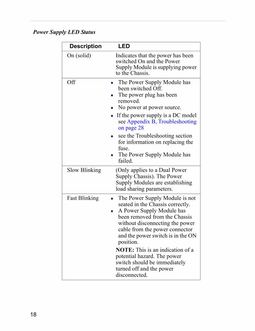
Power Supply LED Status
Description LED
Intelligent Alarm RelayThe Perle MCR1900 Chassis is fashioned with an Intelligent Alarm Relay. This relay is engaged after the unit is powered up and the backplane has been initialized. Should a failure occur, the relay will
On (solid) Indicates that the power has been switched On and the Power Supply Module is supplying power to the Chassis.
Off The Power Supply Module has been switched Off.
The power plug has been removed. No power at power source.Check fuse (DC power supply only). Appendix B, Troubleshooting on page 28
The Power Supply Module has failed.Slow Blinking (Only applies to a Dual Power Supply
Chassis). The Power Supply Modules are establishing load sharing parameters.NOTE: This state will activate the alarm relays.
Fast Blinking The Power Supply Module is not seated in the Chassis correctly.A Power Supply Module has been removed from the Chassis without disconnecting the power cable from the power connector and the power switch is in the ON position. NOTE: This is an indication of a potential hazard. The power switch should be immediately turned off and the power disconnected.
10
be disengaged, therefore setting the alarm until the unit returns to a normal state of operation.A failure can be one of the following:
Loss of power to the Power Supply Module(s).Fan failure.Over temperature heat protection.Over voltage protection.
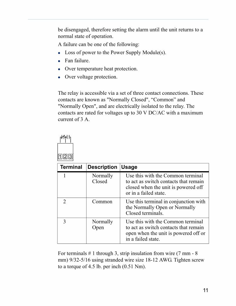
The relay is accessible via a set of three contact connections. These contacts are known as "Normally Closed", “Common” and "Normally Open", and are electrically isolated to the relay. The contacts are rated for voltages up to 30 V DC/AC with a maximum current of 3 A.
For terminals # 1 through 3, strip insulation from wire (7 mm - 8 mm) 9/32-5/16 using stranded wire size 18-12 AWG. Tighten screw to a torque of 4.5 lb. per inch (0.51 Nm).
Terminal Description Usage1 Normally
ClosedUse this with the Common terminal to act as switch contacts that remain closed when the unit is powered off or in a failed state.
2 Common Use this terminal in conjunction with the Normally Open or Normally Closed terminals.
3 Normally Open
Use this with the Common terminal to act as switch contacts that remain open when the unit is powered off or in a failed state.
11

Media Converter ModulesFor information regarding Media Converter Installation, see the appropriate Installation Guide for that product.
12

Installing the MCR1900 Chapter 22
Unpacking the MCR1900 ChassisAvailable Accessories The following accessories can be ordered separately:
What You Need to SupplyBefore you can begin, you need to have the following:
Grounding lug (for improved Chassis grounding).Cross-head screwdriver to attach grounding screws.
Site Preparation RequirementsEasy access to the ports and connectors on the front and back of the Chassis, so that you can connect and disconnect cables as well as view the LEDs.The power outlet(s) should be located near the Chassis and supply reliable electrical power to the Chassis.
Item MCR1900-19-Slot Chassis with one or two AC/DC Power Supplies country specific power cord 19-inch rack mount kitMCR1900 Media Converter 19-Slot Chassis Installation Guide (this guide)
Item Part numberMCR-ACPWR (AC Power Supply Module)
05059810
MCR-DCPWR (DC Power Supply Module)
05059820
Face plate for empty Chassis slots 0505983023-inch rack mount brackets 05059840
13

For proper cooling of the Chassis, air flow around the unit and through the front vents should be unrestricted.Do not expose the Chassis to water or moisture.Do not place objects on top of the Chassis.Place the Chassis in a dust-free environment.If placing the Chassis in a rack, make sure the rack is safely secured.If placing the Chassis on a table, make sure the table is level and secure.
Power RequirementsAC Power RequirementsThe MCR1900 chassis can be powered via an AC source. The following are the ranges for the AC voltage supported by the unit.Minimum: 85 VAC Nominal: 110/240 VAC Maximum: 265 VAC.
DC Power RequirementsThe MCR1900 DC power supply has an integral Terminal Connections block to facilitate connection to a DC source(s). Electrical ground is directly connected by wire to the power supply’s metal tray. The DC supply(s) should have adequate over-current protection within the closed rack system and comply with local or national standards applicable to the installation territory. The following are the ranges for the DC voltage supported by the unit;Minimum: 24 VDC Nominal: 48 VDC Maximum: 60 VDCYou need wire gauge 14 to 18 AWG to connect the MCR1900 chassis to the power source.
WARNINGBefore servicing this product ensure the power source has been disconnected. For dual power supply models, ensure both sources have been disconnected.
14

Grounding the MCR1900 ChassisThe MCR1900 should always be chassis grounded for safe and proper operation.
Grounding the Chassis requires the following items:One grounding lug (not provided).One 12 AWG stranded or 14 AWG solid wire (not provided).Crimping tool (not provided).Cross-head screwdriver (not provided).
The equipment must be grounded for safety and to ensure ESD protection for correct operation and protection of the internal circuitry.
WARNINGBefore servicing this product ensure the power source has been disconnected. For dual power supply models, ensure both sources have been disconnected.
Note: For your safety, when installing this equipment, always ensure that the Chassis Ground connection is installed first and disconnected last.
15
Chassis GroundGrounding Screws
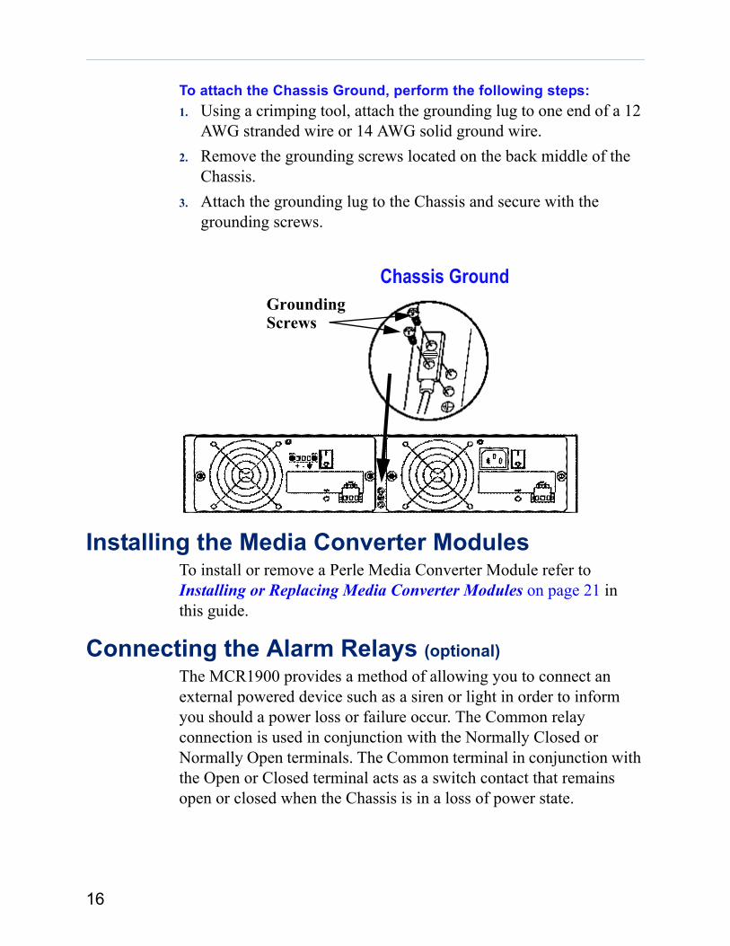
To attach the Chassis Ground, perform the following steps:1. Using a crimping tool, attach the grounding lug to one end of a 12
AWG stranded wire or 14 AWG solid ground wire.2. Remove the grounding screws located on the back middle of the
Chassis.3. Attach the grounding lug to the Chassis and secure with the
grounding screws.
Installing the Media Converter ModulesTo install or remove a Perle Media Converter Module refer to Installing or Replacing Media Converter Modules on page 21 in this guide.
Connecting the Alarm Relays (optional)The MCR1900 provides a method of allowing you to connect an external powered device such as a siren or light in order to inform you should a power loss or failure occur. The Common relay connection is used in conjunction with the Normally Closed or Normally Open terminals. The Common terminal in conjunction with the Open or Closed terminal acts as a switch contact that remains open or closed when the Chassis is in a loss of power state.
16

Powering On an AC Powered ChassisTo power on an AC powered Chassis, perform the following procedure.1. Using the Perle supplied power cord, plug the power cord into the
AC power connector at the rear of the Chassis (repeat this procedure if you have a second power supply installed in the Chassis).
2. Plug the other end of the power cord to an appropriate power outlet (repeat this procedure if you have a second power supply installed in the Chassis).
3. Turn the power switch(s) to the On position.4. A solid green LED indicates the chassis is powered up.
Powering On an DC Powered ChassisTo power on an DC powered Chassis, perform the following procedure.
1. Locate the Barrier strip connector on the back of the DC power supply module. Remove the covering plastic shield to expose the three screw terminals ( + - Gnd)
2. On each end wire, remove the insulation from the copper wire 5 mm (3/16 of an inch).
3. First connect the electrical ground wire by loosening the right screw terminal (Gnd) and wrap the end wire tightly around the screw. Tighten the screw securely.
4. Loosen the left screw terminal (positive +) and wrap the end wire tightly around the screw. Tighten the screw securely.
5. Loosen the middle screw terminal (negative -) and wrap the end wire tightly around the screw. Tighten the screw securely.
6. Repeat this procedure if you have a second DC power supply.7. Apply power at source.8. A solid green LED indicates the chassis is powered up.
Note: Ensure power is NOT applied to the wires prior to connection.
17
Power Supply LED Status
Description LEDOn (solid) Indicates that the power has been
switched On and the Power Supply Module is supplying power to the Chassis.
Off The Power Supply Module has been switched Off.The power plug has been removed. No power at power source.
If the power supply is a DC model see Appendix B, Troubleshooting on page 28see the Troubleshooting section for information on replacing the fuse.The Power Supply Module has failed.
Slow Blinking (Only applies to a Dual Power Supply Chassis). The Power Supply Modules are establishing load sharing parameters.
Fast Blinking The Power Supply Module is not seated in the Chassis correctly.A Power Supply Module has been removed from the Chassis without disconnecting the power cable from the power connector and the power switch is in the ON position.
NOTE: This is an indication of a potential hazard. The power switch should be immediately turned off and the power disconnected.
18

Warning For your safety, before attempting to connect or modify any of the electrical connections to the unit, please be sure all wiring is disconnected from any live power source. Power should only be applied when you are sure that the wiring is correct and any safety covers are properly installed.
19

20

Media Converter Modules Chapter 33
Installing or Replacing Media Converter Modules
The Perle Media Converter Modules may be installed in any order and in any available installation slot. All Perle Media Converter Modules are hot-swappable and can be removed or installed while the Chassis is powered on.
Removing Media Converter Modules1. Loosen the captive retainer screw on the front of the Media
Converter Module and gently pull the module towards you.2. If not inserting a replacement Media Converter Module then cover
the opening slot with a face plate and secure the screw.
Installing or Replacing Media Converter Modules1. If installing or replacing your Media Converter Module, remove the
Media Converter Module from its packaging.2. Using a cross-head screwdriver, remove the screw holding the face
plate to reveal the slot opening.3. Set the Modules DIP switches to the desired operating mode (refer to
the Installation Guide that came with the Media Converter Module).4. Locate the top and bottom alignment guides inside the Media
Converter Module slot.5. Using the module alignment guides gently slide the module into the
slot until it becomes flush with the front of the Chassis. Light pressure may be needed to seat the module. Do not force the module
Warning Observe electrostatic discharge precautions when installing the Media Converter Module(s) into the Chassis. Failure to observe this precaution could result in damage to the Media Converter Module.
21

Captive screws
Captiveretainer screw
as you might damage the module. If there is resistance, remove the module and check the module’s backplane connector for damage to the pins. If the module’s backplane conector is not damaged, retry the insertion.
6. Tighten the Captive retainer screw to ensure the Media Converter Module is locked in place.
7. Remove the dustcap from the fiber connector and connect the fiber and copper cables.
Note: All open slots in the Chassis must be covered with a face plate in order to maintain proper air circulation throughout the Chassis.
22
Power Supply Modules Chapter 44
Installing or Replacing the Power Supply ModuleNote: Use these procedures for AC or DC power supply modules.
The MCR1900 Power Supply Module is hot-swappable and can be removed or installed while the Chassis is powered on. The MCR1900 comes with two Power Supply Bays with one or two Power Supply Module(s) installed. To remove or replace a Power Supply Module, perform the following procedure:
Removing the Power Supply Module1. Turn the power switch to the Off position.2. Disconnect the power cord from its source.3. Disconnect the power cord from the MCR1900 Power Supply
Module.
4. Disconnect the alarm relay connections if connected.5. Using a screwdriver remove the one screw located at the top of the
Power Supply Module.
Warning Never attempt to open or service a Power Supply Module. Opening the Power Supply Module may cause serious injury or death.
Warning Failure to follow these steps may result in a live Power Supply Module and present a potential hazard.
23
6. Loosen the captive retainer screws on either side of the Power Supply Module.
7. Gently pull the Power Supply Module towards you. If replacing the Power Supply Module, follow the procedure below. If not replacing the Power Supply Module then cover the open Bay with a Power Supply Bay cover and replace the screws.
Installing or Replacing the Power Supply Module1. If installing or replacing the Power Supply Module, remove it
from its packaging.2. Using a cross-head screwdriver, remove the screw from the top of
the Power Supply Bay cover on the back of the Chassis and remove the cover.
3. Locate the bottom alignment guide inside the Power Supply Bay.4. Using the Power Supply module alignment guide gently slide the
module into the Bay until it becomes flush with the back of the Chassis. Light pressure may be needed to seat the module. Do not force the module as you might damage the connector. If there is resistance, remove the module and try again.
5. Using a screwdriver secure the one screw located at the top of the Power Supply Module.
6. Tighten the Captive retainer screws on either side of the Power Supply Module.
7. Connect the power cord to the MCR1900 Power Supply Module.8. Connect the power cord its source.9. If this is a DC Power Supply see section "Powering On an DC
Powered Chassis"10. Connect the alarm relays (optional).
24
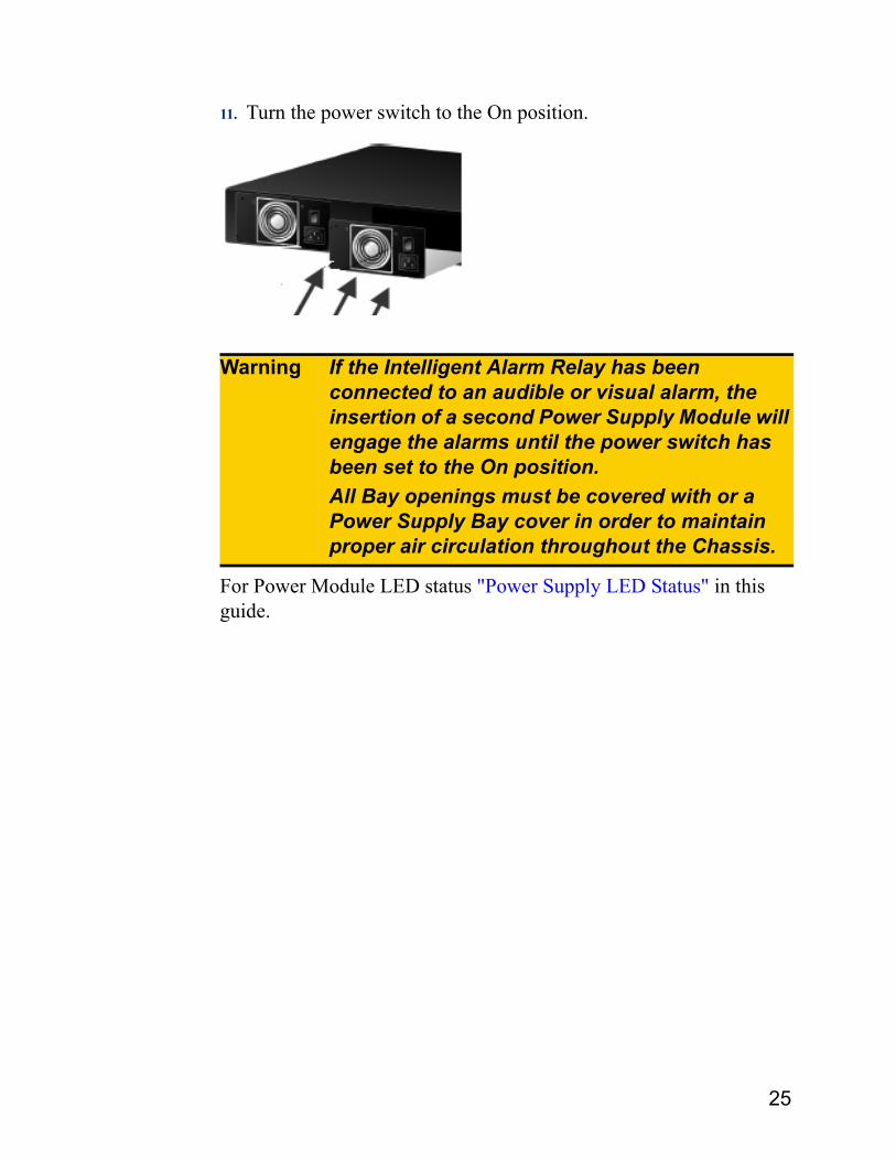
11. Turn the power switch to the On position.
For Power Module LED status "Power Supply LED Status" in this guide.
Warning If the Intelligent Alarm Relay has been connected to an audible or visual alarm, the insertion of a second Power Supply Module will engage the alarms until the power switch has been set to the On position.All Bay openings must be covered with or a Power Supply Bay cover in order to maintain proper air circulation throughout the Chassis.
25

Technical Specifications Appendix AA
Environmental Specifications* Designed and tested for normal operation for altitudes up to 3048 m (10,000 ft.): safety approvals apply only to an operating altitude of 2000 m (6500 ft.).
Physical Specifications
Operating Temperature 0 oC to 50 oC (32 oF to 122 oF)Storage Temperature -25 oC to 70 oC
-13 oF to 150 oFO p e r a t i n g / St o r a g e Humidity
5% to 95% (non condensing).
Operating Altitude Sea level to 3048 m (10,000ft)*
Weight 6.32 kg. (13.9 labs.)Size 2UDimensions(D X H X W)
356 mm by 435 mm by 89 mm14 in. by 17.2 in. by 3.5 in.
Ventilation Method Front to back of Chassis
26
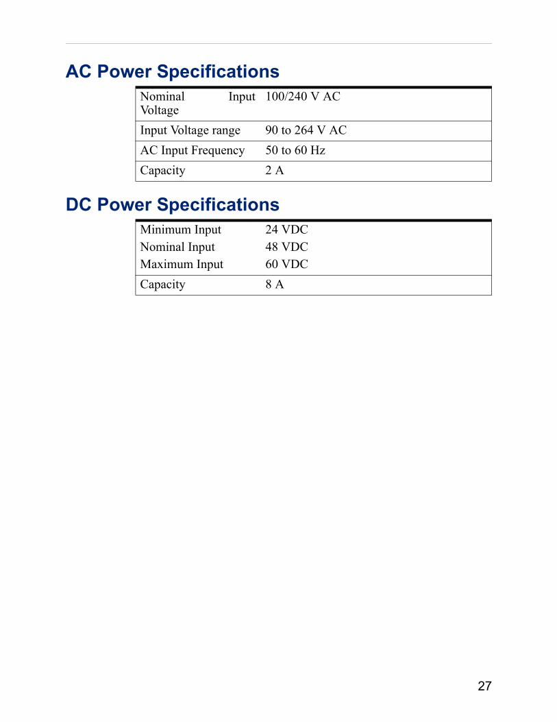
AC Power Specifications
DC Power Specifications
Nominal Input Voltage
100/240 V AC
Input Voltage range 90 to 264 V ACAC Input Frequency 50 to 60 HzCapacity 2 A
Minimum InputNominal Input Maximum Input
24 VDC48 VDC60 VDC
Capacity 8 A
27

Troubleshooting Appendix BB
This chapter provides information that can help resolve issues with your Perle MCR1900 Chassis.Intelligent Alarm RelayThe relay can be engaged for any of the following conditions.
Condition Possible CauseLoss of Power Loss of power source to the Power
Supply Module.Power switch is in the Off position.Power Supply Module hardware failure.
Fan not running The fan is running at less then 50% speed rate.
The fan has failed. Over Temperature Protection
Ensure that the fans are operational.Ensure the ambient temperature is within the specifications.
28

Power Supply LED StatusDescription LED
On (solid) Indicates that the power has been switched On and the Power Supply Module is supplying power to the Chassis.
Off The Power Supply Module has been switched Off.
The power plug has been removed. No power at power source.Replace fuse (DC power supply only).The Power Supply Module has failed.
Slow Blinking (Only applies to a Dual Power Supply Chassis). The Power Supply Modules are establishing load sharing parameters.
Fast Blinking The Power Supply Module is not seated in the Chassis correctly.
A Power Supply Module has been removed from the Chassis without disconnecting the power cable from the power connector and the power switch is in the ON position.
NOTE: This is an indication of a potential hazard. The power switch should be immediately turned off and the power disconnected.
Note: DC power supplies have reversed polarity protection. Fuse types Cooper/Bussmann GMA-8-R and Littelfuse 0477008.MXP are recommended.
29