Embed Size (px)
Citation preview

MCR-MGT Management Module
Command Line InterfaceGuide
December 2017
Version A.12.22.2017
Part #5500311-16 (Rev B)

Copyright Statement
This document must not be reproduced in any way whatsoever, either printed or electronically, without the consent of:
Perle Systems Limited,60 Renfrew DriveMarkham, ONCanada L3R 0E1
Perle reserves the right to make changes without further notice, to any products to improve reliability, function, ordesign.
Perle Systems Limited, 2010 - 2017.

Table of Contents
Preface .................................................................................9
About This Book .......................................................................... 9
Intended Audience....................................................................... 9
Typeface Conventions................................................................. 9
Chapter 1 Introduction......................................................10
CLI Conventions ........................................................................ 10
Command Syntax ................................................................................... 10
Command Shortcuts .............................................................................. 10
Command Options ................................................................................. 11
Chapter 2 MCR-MGT Module Specific Commands ........12
MCR-MGT Server Commands................................................... 12
Set Server................................................................................................ 12
Show Server............................................................................................ 13
Set Service .............................................................................................. 13
Set Display Format ................................................................................. 14
Show Display Format ............................................................................. 14
SSH Server Commands............................................................. 15
Set SSH-Server ....................................................................................... 15
Show SSH-Server ................................................................................... 16
Hardware Commands ................................................................ 17
Set Console............................................................................................. 17
Show Console......................................................................................... 17
Set Ethernet ............................................................................................ 17
MCR-MGT Management Module CLI Reference Guide 3

Show Hardware....................................................................................... 18
Authentication Commands ....................................................... 19
Set authentication .................................................................................. 19
Set authentication Kerberos.................................................................. 19
Set authentication LDAP/Active Directory ........................................... 19
Set authentication NIS ........................................................................... 21
Set Authentication RADIUS................................................................... 21Add RADIUS ...................................................................................... 22Delete RADIUS .................................................................................. 22
Set Authentication TACACS+................................................................ 22
Set Authentication SecurID ................................................................... 23
Show Authentication.............................................................................. 24
Email Commands....................................................................... 25
Set Email-Alert Server............................................................................ 25
Show Email-Alert Server........................................................................ 26
Dynamic DNS Commands......................................................... 27
Set Dynamic-DNS ................................................................................... 27
Set Dynamic-DNS SSL ........................................................................... 27
Set Dynamic-DNS SSL Cipher-Suite..................................................... 29
Show Dynamic-DNS ............................................................................... 30
IPv6 Commands ......................................................................... 31
Set IPv6.................................................................................................... 31
Show IPv6................................................................................................ 31
Add Custom-IPv6 (Set Custom-IPv6).................................................... 31
Delete Custom-IPv6................................................................................ 32
Chapter 3 Chassis/slot Commands ................................33
Chassis Commands................................................................... 33
Set Chassis Temperature-Threshold.................................................... 33
Set Chassis serial................................................................................... 33
Set Chassis management-module-slot ................................................ 33
Set slot common parameters ................................................................ 34
Set slot, power schedule ....................................................................... 34
MCR-MGT Management Module CLI Reference Guide 4

Slot Control Commands............................................................ 35
Slot reset ................................................................................................. 35
Slot reset to factory................................................................................ 35
Slot power ............................................................................................... 35
Slot virtual-cable-test ............................................................................. 35
Slot loopback.......................................................................................... 35
Slot register read/write........................................................................... 35
Slot link-test ............................................................................................ 36
Slot sfp/xfp (read memory) .................................................................... 36
Slot Configuration Commands ................................................. 37
Set slot... cm-100 .................................................................................... 37
Set slot... cm-100mm.............................................................................. 38
Set slot... cm-1000 .................................................................................. 38
Set slot... cm-1000mm............................................................................ 40
Set slot... cm-110 .................................................................................... 41
Set slot... cm-1110 .................................................................................. 46
Set slot... cm-10g.................................................................................... 51
Set slot... cm-10gt................................................................................... 53
Set slot... cm-4gpt................................................................................... 55
Set slot... ex............................................................................................. 56
set slot... cm-10gr ................................................................................... 60
set slot... cm-10grt.................................................................................. 65
Show slot * command ............................................................................ 69
Show slot # command............................................................................ 70
Show chassis alerts ............................................................................... 70
Show chassis details ............................................................................. 70
Chapter 4 User Commands ..............................................71
Commands for active sessions ................................................ 71
Admin ...................................................................................................... 71
Help.......................................................................................................... 71
Logout ..................................................................................................... 71
Menu ........................................................................................................ 71
Ping.......................................................................................................... 71
MCR-MGT Management Module CLI Reference Guide 5

Screen...................................................................................................... 72
Set Termtype........................................................................................... 72
Syslog Console....................................................................................... 72
Show Termtype....................................................................................... 72
Version .................................................................................................... 72
Configuring Users...................................................................... 72
Add User.................................................................................................. 72
Delete User.............................................................................................. 73
Set User ................................................................................................... 73
Show User ............................................................................................... 73
Chapter 5 Network Commands ........................................74
SNMP Commands ...................................................................... 74
Add Community...................................................................................... 74
Set SNMP................................................................................................. 74
Set SNMP V3-Security............................................................................ 75
Set snmp-trap common ......................................................................... 75
Set snmp-trap entry................................................................................ 75
Set snmp-trap v3 .................................................................................... 76
Delete Community .................................................................................. 77
Show SNMP............................................................................................. 77
Hosts Commands ...................................................................... 78
Add Host.................................................................................................. 78
Delete Host.............................................................................................. 78
Set Host ................................................................................................... 78
Show Hosts............................................................................................. 78
Add Authorized Host.............................................................................. 79
Delete Authorized Host .......................................................................... 79
Set Authorized Host ............................................................................... 79
Show Authorized Hosts ......................................................................... 79
DNS Commands......................................................................... 80
Add DNS.................................................................................................. 80
Delete DNS .............................................................................................. 80
MCR-MGT Management Module CLI Reference Guide 6

Show DNS ............................................................................................... 80
Gateway Commands.................................................................. 81
Add Gateway........................................................................................... 81
Delete Gateway....................................................................................... 81
Set Gateway ............................................................................................ 81
Show Gateways ...................................................................................... 82
Logging Commands .................................................................. 83
Set Syslog ............................................................................................... 83
Show Syslog ........................................................................................... 83
Set event-log........................................................................................... 83
IPv6 Tunnels............................................................................... 84
Add IPv6tunnel ....................................................................................... 84
Set IPv6tunnel......................................................................................... 84
Show IPv6tunnel..................................................................................... 84
Delete IPv6tunnel.................................................................................... 84
Chapter 6 Administration Commands.............................85
Administration Commands ....................................................... 85
Reboot ..................................................................................................... 85
Reset Factory.......................................................................................... 85
Set Firmware auto-update ..................................................................... 85
Show Firmware auto-update ................................................................. 85
Save ......................................................................................................... 85
Set Bootup .............................................................................................. 85
Show text-config..................................................................................... 86
Show Bootup .......................................................................................... 86
TFTP File Transfer Commands................................................. 87
Netload configuration and firmware ..................................................... 87
Netsave configuration............................................................................ 87
Keys and Certificates Commands............................................ 89
Netload keys ........................................................................................... 89
Netsave keys........................................................................................... 89
MCR-MGT Management Module CLI Reference Guide 7

Netload Media Converter Modules........................................................ 90
Netload Serialt-buf.................................................................................. 90
Netload sntp-keys................................................................................... 90
Chapter 7 Time Commands..............................................91
Time Commands ........................................................................ 91
Set Time................................................................................................... 91
Set Timezone .......................................................................................... 91
Show Time............................................................................................... 91
Show Timezone ...................................................................................... 91
SNTP Commands....................................................................... 92
Add SNTP................................................................................................ 92
Delete SNTP ............................................................................................ 92
Set SNTP ................................................................................................. 92
Show SNTP ............................................................................................. 93
Show SNTP-Info...................................................................................... 93
Time/Date Setting Commands .................................................. 94
Set Date ................................................................................................... 94
Set Summertime ..................................................................................... 94
Set Summertime Fixed........................................................................... 94
Set Summertime Recurring ................................................................... 94
Show Date ............................................................................................... 95
Show Summertime ................................................................................. 95
Chapter 8 Statistics Commands ......................................96
Configuration Statistics ............................................................ 96
Show Interface........................................................................................ 96
Run-Time Statistics ................................................................... 96
Delete Arp................................................................................................ 96
Show Arp................................................................................................. 96
Uptime ..................................................................................................... 96
MCR-MGT Management Module CLI Reference Guide 8

MCR-MGT Management Module CLI Reference Guide 9
Preface
About This BookThis guide provides the information you need to:
configure the MCR-MGT Management Module using the Command Line Interface (CLI)
Intended AudienceThis guide is for administrators who will be configuring the MCR-MGT Management Module.
Some prerequisite knowledge is needed to understand the concepts and examples in this guide:
If you are using an external authentication application(s), working knowledge of the authentication application(s).
Knowledge of TFTP the transfer protocols the MCR-MGT Management Module uses.
Typeface ConventionsMost text is presented in the typeface used in this paragraph. Other typefaces are used to help you identify certain types of information. The other typefaces are:
Typeface Example Usage
At the C: prompt, type: add host
This typeface is used for code examples and system-generated output. It can represent a line you type in, or a piece of your code, or an example of output.
Set the value to TRUE. The typeface used for TRUE is also used when referring to an actual value or identifier that you should use or that is used in a code example.
subscribe project subject
run yourcode.exec
The italicized portion of these examples shows the typeface used for variables that are placeholders for values you specify. This is found in regular text and in code examples as shown. Instead of entering project, you enter your own value, such as stock_trader, and for yourcode, enter the name of your program.
MCR-MGT Management Module User’s Guide
This typeface indicates a book or document title.
See About This Book on page 9 for more information.
This indicates a cross-reference to another chapter or section that you can click on to jump to that section.
Introduction Chapter 11
CLI ConventionsThis section explains how to interpret the CLI syntax. Not all CLI commands are available on all product models.
Command SyntaxEach command is broken down into several categories:
Description—Provides a brief explanation of how the command is used.
User Level—Shows which user level(s) (Operator and/or Admin) can issue the command.
Syntax—Shows the actual command line options. The options can be typed in any order on the command line. The syntax explanation will use the following command to break down the command syntax:
set service [telnetd on|off] [sshd on|off] [httpd on|off] [httpsd on|off] [snmpd on|off] [setip on|off]
– Square brackets ([]) show the options that are available for the command. You can type a command with each option individually, or string options together in any order you want. For example,
set service sshd on telnetd off
– Angle brackets (<>) show that the text inside the brackets is a description for a variable value that you must fill in according to your requirements. In the set server command, you must determine the values for domain, internet, name, password-limit, and subnet-bit-length, if you wish to specify them and not use their defaults (default values provided in the Options description). The angle brackets can also contain a range that can be used.
– The pipe (|) shows an ’or’ condition. For example, valid values for telnetd are either on or off.
Options—Provides an explanation of each of the options for a command and the default value if there is one. Some commands do not have any options, so this category is absent.
Command ShortcutsWhen you type a command, you can specify the shortest unique version of that command or you can press the ESC or TAB key to complete the command. For example, the following command:
set ethernet crossover auto
can be typed as:
set eth cro a
Introduction 10

CLI Conventions
or, you can use the ESC key to complete the lines as you go along:
set eth<ESC>ernet cr<ESC>ossover a<ESC>uto
where the ESC key was pressed to complete the option as it was typed.
Command OptionsWhen you are typing commands on the command line (while connected to the MCR-MGT Management Module), you can view the options by typing a question mark (?), ESC, or TAB key after any part of the command to see what options are available/valid. For example:
MCR-MGT-100903#set console ?data-bitsflowmodemonitor-dsrparityspeedstop-bitsMCR-MGT-100903#set console mode ?disabledenabledMCR-MGT-100903#set console mode enabled ?data-bitsflowmodemonitor-dsrparityspeedstop-bitsOr press <ENTER> to confirm commandMCR-MGT-100903#set console mode enabledMCR-MGT-100903#
Introduction 11

MCR-MGT Module Specific Commands Chapter 22
MCR-MGT Server Commands
Set Server
Description Sets high level parameters for the MCR-MGT Management Module.User Level AdminSyntax set server [auto-obtain-dns][auto-obtain-gw][dhcp-update-dns]
[domain <text>][name <text>][incoming-pings enabled|disabled][internet dhcp/bootp on|off|<ipv4-address>][netmask <ipv4-address>][session-timeout <number in seconds>]tftp][ssl-passphrase <text>]
auto-obtain-dns When DHCP/BOOTP is enabled, the MCR-MGT Management Module will receive the DNS IP address from the DHCP/BOOTP server.
auto-obtain-gw When DHCP/BOOTP is enabled, the MCR-MGT Management Module will receive the Default Gateway IP address from the DHCP/BOOTP server.
dhcp-update-dns When this parameter is set, the MCR-MGT Management Module will provide the DHCP server with a fully qualified domain name (FQDN), so that the DHCP server can update the network's DNS server with the newly assigned IP address.
Default: Disabled
domain This field is combined with the System Name to construct the fully qualified domain name (FQDN). For example, if the domain is mycompany.com and the Server Name is set to accounting, the FQDN would be accounting.mycompany.com.
incoming-pings The MCR-MGT management module will respond to incoming pings.
Default: Enabled
name The System Name is used for informational purposes by such tools as the MCR Web Manager and is also used in conjunction with the Domain field to construct a fully qualified domain name (FQDN).
Default: MCR-MGT-xxxxxx (where xxxxxx is the last 6 digits of the Management Module’s MAC address).
internet This option excepts one of two parameters, ipv4 address or dhcp/bootp.
ipv4 address - this parameter is followed by the IP address you wish to set for the Ethernet interface on the MCR-MGT Management Module.
dhcp/bootp - this parameter is followed by an "on" or "off" directive. It enables or disables the use of DHCP as a method for obtaining the IP information for the Ethernet port of the MCR-MGT Management Module.
netmask The IPv4 subnet mask you wish to assign to the MCR-MGT management module’s Ethernet port. For example, 255.255.0.0
MCR-MGT Management Module CLI Reference Guide 12

MCR-MGT Server Commands
Show Server
Set Service
session- timeout The session inactivity timer is only used when “Bypass login” is not enabled (i.e. login is required). If no activity is detected on the session for the amount of time configured here in seconds, the session will be terminated. The default timeout is 3600 seconds (60 minutes)
tftp This option takes up to two parameters, retry and timeout.
Retry is the number of times the Management Module will retry to transmit a TPFT packet to/from a host when no response is received. Enter a value between 0 and 5. The default is 5. A value of 0 (zero) means no retry.
Timeout, in seconds, that the Management Module will wait for a successful transmit or receipt of TFTP packets before retrying a TFTP transfer. Enter a value between 3 and 10. The default is 3 seconds.
ssl-passphrase This is the SSL/TLS passphrase used to generate an encrypted RSA/DSA private key. This private key and passphrase are required for both HTTPS and SSL/TLS connections, unless an unencrypted private key was generated, then the SSL passphrase is not required. Make sure that you download the SSL private key and certificate if you are using the secure HTTP option (HTTPS) or SSL/TLS. If both RSA and DSA private keys are downloaded to the MCR-MGT Management Module, they need to be generated using the same SSL passphrase for both to work.
Description Shows the parameters set for the server.User Level Admin, OperatorSyntax show server
Description Enables or disables the given service on the MCR-MGT Management Module. If disabled, the module does not listen for connections on that service.
User Level AdminSyntax set service [telnetd] [sshd] [httpd] [httpsd] [snmpd]
[setip]
For each service above, you can enter "on" or "off" to enable or disable the service.
MCR-MGT Module Specific Commands 13
MCR-MGT Server Commands
Set Display Format
Show Display Format
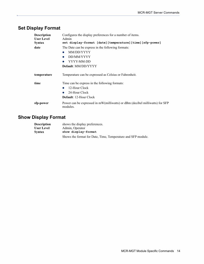
Description Configures the display preferences for a number of items.User Level AdminSyntax set display-format [date][temperature][time][sfp-power]
date The Date can be express in the following formats:
MM/DD/YYYY
DD/MM/YYYY
YYYY-MM-DD
Default: MM/DD/YYYY
temperature Temperature can be expressed as Celsius or Fahrenheit.
time Time can be express in the following formats:
12-Hour Clock
24-Hour Clock
Default: 12-Hour Clock
sfp-power Power can be expressed in mW(milliwatts) or dBm (decibel milliwatts) for SFP modules.
Description shows the display preferences.User Level Admin, OperatorSyntax show display-format
Shows the format for Date, Time, Temperature and SFP module.
MCR-MGT Module Specific Commands 14

SSH Server Commands
SSH Server Commands
Set SSH-ServerSee Keys and Certificates in the MCR-MGT Management User’s Guide for information about the keys and certificates that need to be uploaded or downloaded with the MCR-MGT Management Modules SSH server.
Description Configures the MCR-MGT Management Modules SSH server.User Level AdminSyntax set ssh-server [authentication [RSA[on|off][|DSA
on|off]|[keyboard-interactive on|off][password on|off][compression on|off][verbose on|off]][ssh1 on|off] [cipher 3des|blowfish|aes|cast|arcfour|aes-ctr|aes-gcm|chachapoly1305]
authentication Defines the authentication method to be used by the MCR-MGT Management Module’s SSH server. The valid options are;
RSA
DSA
Keyboard-interactive
Password. - (only valid for SSH1).
You can select one or more options. The authentication method is followed by "on" or "off" to enable or disable this authentication method.
compression This parameter enables or disables compression. Typically compression is not required on fast networks (may actually slow things down). The valid options are;
On - turn compression on.
Off - turn compression off.verbose Displays debug messages on the terminal.
On - turn on debug.
Off - turn off debug.
ssh1 Allows the user’s client to negotiate an SSH-1 connection, in addition to SSH-2.
On - turn on ssh1.
Off - turn off ssh1.
cipher This parameter defines the ciphers which will be negotiated with the client. The following ciphers can be enabled;
3des
blowfish
aes
cast
arcfour
aes-ctr
aes-gcm
chacha20-poly1305
You can select one or more options. The cipher is followed by "on" or "off" to have it included or not included in the negotiated list.
MCR-MGT Module Specific Commands 15

SSH Server Commands
Show SSH-ServerDescription Shows the SSH server settings.User Level Admin, OperatorSyntax show ssh-server
MCR-MGT Module Specific Commands 16
Hardware Commands
Hardware Commands
Set Console
Show Console
Set Ethernet
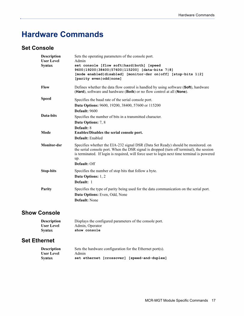
Description Sets the operating parameters of the console port.User Level AdminSyntax set console [flow soft|hard|both] [speed
9600|19200|38400|57600|115200] [data-bits 7|8] [mode enabled|disabled] [monitor-dsr on|off] [stop-bits 1|2] [parity even|odd|none]
Flow Defines whether the data flow control is handled by using software (Soft), hardware (Hard), software and hardware (Both) or no flow control at all (None).
Speed Specifies the baud rate of the serial console port.
Data Options: 9600, 19200, 38400, 57600 or 115200
Default: 9600Data-bits Specifies the number of bits in a transmitted character.
Data Options: 7, 8
Default: 8Mode Enables/Disables the serial console port.
Default: Enabled
Monitor-dsr Specifies whether the EIA-232 signal DSR (Data Set Ready) should be monitored. on the serial console port. When the DSR signal is dropped (turn off terminal), the session is terminated. If login is required, will force user to login next time terminal is powered up.
Default: Off
Stop-bits Specifies the number of stop bits that follow a byte.
Data Options: 1, 2
Default: 1
Parity Specifies the type of parity being used for the data communication on the serial port.
Data Options: Even, Odd, None
Default: None
Description Displays the configured parameters of the console port.User Level Admin, OperatorSyntax show console
Description Sets the hardware configuration for the Ethernet port(s).User Level AdminSyntax set ethernet [crossover] [speed-and-duplex]
MCR-MGT Module Specific Commands 17

Hardware Commands
Show Hardware
crossover This options sets the method by which the Ethernet’s cable polarity will be set. The following options are available;
Auto— automatically detects the Ethernet’s cable polarity MDI —the cable’s polarity is straight-through MDI-X —the cable’s polarity is crossoveredThe default setting for this parameter is "Auto"
speed-and-duplex Define the Ethernet connection.
Data Options: Auto—automatically detects the Ethernet interface speed and duplex 10 Mbps/Half Duplex 10 Mbps/Full Duplex 100 Mbps/Half Duplex 100 Mbps/Full Duplex 1000 Mbps/Half Duplex
Default: Auto
Description Shows the hardware resources, Ethernet link status, date and time.User Level Admin, OperatorSyntax show hardware
MCR-MGT Module Specific Commands 18

Authentication Commands
Authentication Commands
Set authentication
Set authentication Kerberos
Set authentication LDAP/Active Directory
Description Sets the authentication method for the MCR-MGT Management Module.User Level AdminSyntax set authentication [type primary|secondary
raduis|kerberos|ldap|nis|securid|tacacs+|none] [bypass-login on|off] [secondary-as-backup disabled|enabled]
type You can define up to two authentication methods which will be used to grant access to users accessing the MCR-MGT Management Module. The type parameter defines which method is used first as well as the type of authentication associated with that method.
The first parameter for type is the designation of "primary" or "secondary". The "primary" authentication method is the one that the MCR-MGT Management Module attempts first. If a secondary method is also defined, it may or not be used depending on the setting of the "secondary-as-backup" parameter.
The next parameter after the "primary" or "secondary" will be the authentication type. The following types can be specified.
radius, kerberos, ldap, nis, securid, tacacs+ or none.bypass-login This defines whether users accessing the MCR-MGT Management Module will be
required to login before gaining access the unit. The next parameter is as follows;
on - users will be required to login.
off - users will not be required to login.
secondary-
as-backupIf this option is selected (enabled), the secondary authentication method will only be attempted if the MCR-MGT module can not reach the primary authentication host. (i.e. if the primary authentication host indicates that the user does not have access, the secondary authentication method will not be attempted). In other words, the secondary is only used as a backup to the primary in case the primary is not available.
If this options is not selected (disabled), the secondary authentication will always be tried if the primary authentication is not successful (for any reason including an indication from the primary that the user is not authenticated).
Default: Disabled (not selected).
Description Configures Kerberos authentication settings.User Level AdminSyntax set authentication kerberos [kdc-domain <text>] [port <number>]
[realm <text>]
kdc-domain The name of a host running the KDC (Key Distribution Center) for the specified realm. The host name that you specify must either be defined in the MCR-MGT Management Module’s Host Table before the last reboot or be resolved by DNS.
port The port that the Kerberos server listens to for authentication requests.
Default: 88
realm The Kerberos realm is the Kerberos host domain name, in upper-case letters.
Description Configures LDAP/Active Directory authentication settings.User Level Admin
MCR-MGT Module Specific Commands 19

Authentication Commands
Syntax set authentication ldap [base] [client append-base|authenticate|name|password] [encrypt-password] [host] [port] [tls] [tls-port] [user-attribute other|sAMAccountName|uid]
base The domain component (dc) that is the starting point for the search for user authentication.
client Enables/disables appending the base domain component (dc) to the client name field. En-ables/disables whether the MCR-MGT Management Module will authenticate itself tothe LDAP Server. The name to be used by the MCR-MGT Management Module to au-thenticate to the LDAP Server. The password to be used when authenticating to theLDAP Server
aon and off
encrypt-password When followed by the "MD5" parameter, the MCR-MGT Management Module will encrypt the user’s and the MCR-MGT Management Module password strings using MD5 digest. If followed by "none", no encryption will be performed.
host The name or IP address of the LDAP/Microsoft Active Directory host. If you use a host name, that host must either have been defined in the MCR-MGT Management Module’s Host Table before the last reboot or be resolved by DNS. If you are using TLS, you must enter the same string you used to create the LDAP certificate that resides on your LDAP/Microsoft Active Directory server.
port The port that the LDAP/Microsoft Active Directory host listens to for authentication requests.
Default: 389
tls Enables/disables the Transport Layer Security (TLS) with the LDAP/Microsoft Active Directory host.
Default: Disabled.
tls-port Specify the port number that LDAP/Microsoft Active Directory will use for TLS.
Default: 636
user-attribute This defines the name of the attribute used to communicate the user name to the server.
Options:
OpenLDAP(uid)—Chose this option if you are using an OpenLDAP server. The user attribute on this server is “uid”.
Microsoft Active Directory(sAMAccountName)—Chose this option if your LDAP server is a Microsoft Active Directory server. The user attribute on this server is “sAMAccountName”.
Other—If you are running something other than a OpenLDAP or Microsoft Active Directory server, you will have to find out from your system administrator what the user attribute is and enter it in this field.
Default: OpenLDAP(uid)
MCR-MGT Module Specific Commands 20

Authentication Commands
Set authentication NIS
Set Authentication RADIUS
Description Sets NIS authentication parameters.User Level AdminSyntax set authentication nis [domain] [primary] [secondary]
domain The NIS domain name.
primary The primary NIS host that is used for authentication.
Default: None
secondary The secondary NIS host that is used for authentication, should the primary NIS host fail to respond.
Default: None
Description Sets RADIUS parameters.User Level AdminSyntax set authentication radius [accounting] acct-authenticator]
[acct-port][auth-port]attributes [nas-identifier|nas-ip-address|nas-ipv6-address] [retry][timeout]
accounting Enables/disables RADIUS accounting.
Default: Disabled
acct-authenticator Enables/disables whether or not the MCR-MGT Management Module validates the RADIUS accounting response.
Default: Enabled
acct-port The port that the RADIUS host listens to for accounting requests.
Default: 1813
auth-port The port that the RADIUS host listens to for authentication requests.
Default: 1812
attributesnas-identifier This is the string that identifies the Network Address Server (NAS) that is originating
the Access-Request to authenticate a user.
Field Format: Maximum 31 characters, including spaces
nas-ip-address When enabled, the MCR-MGT Management Module will send the MCR-MGT Management Module’s Ethernet IPv4 address to the RADIUS server.
Default: Enabled
nas-ipv6-address When enabled, the MCR-MGT Management Module will send the specified IPv6 address to the RADIUS server.
Default: Disabled
retry The number of times the MCR-MGT Management Module tries to connect to the RADIUS server before erroring out.
Range: 0-255
Default: 5
MCR-MGT Module Specific Commands 21

Authentication Commands
Add RADIUS
Delete RADIUS
Set Authentication TACACS+
timeout The time, in seconds, that the MCR-MGT Management Module waits to receive a reply after sending out a request to a RADIUS accounting or authentication host. If no reply is received before the timeout period expires, the MCR-MGT Management Module will retry the same host up to and including the number of retry attempts.
Range: 1-255
Default: 3 seconds
Description Adds an accounting or authentication RADIUS host.User Level AdminSyntax add radius [accounting-host] [auth-host]
accounting-host The first time this command is entered, this is the name of the primary RADIUS accounting host.
The second time this command is entered, this is the name of the secondary RADIUS accounting host.
auth-host The first time this command is entered, this is the name of the primary RADIUS authentication host.
The second time this command is entered, this is the name of the secondary RADIUS authentication host, should the first RADIUS host fail to respond.
secret For both of the above, you can specify the "secret" associated with each host. The secret is the password which is shared between the MCR-MGT Management Module and the RADIUS host.
After typing the command secret and pressing Enter, you will be prompted to enter the secret and then re-enter the secret.
Description Deletes an accounting or authentication RADIUS host.User Level AdminSyntax delete radius [accounting] [authentication]
accounting Deletes the specified accounting host from the RADIUS authentication settings.
authentication Deletes the specified authentication host from the RADIUS authentication settings.
Description Configures TACACS+ authentication settings.User Level AdminSyntax set authentication tacacs+ [port] [primary] [secondary]
[secret][alternate-service-names][authorization] [accounting] [acct-port] [acct-primary] [acct-secondary] [acct-secret]
port The port number that TACACS+ listens to for authentication requests.
Default: 49
primary The primary TACACS+ host that is used for authentication.
Default: None
secondary The secondary TACACS+ host that is used for authentication, should the primary TACACS+ host fail to respond.
Default: None
MCR-MGT Module Specific Commands 22

Authentication Commands
Set Authentication SecurID
secret The TACACS+ shared secret is used to encrypt/decrypt TACACS+ packets in communications between two devices. The shared secret may be any alphanumeric string up to 30 characters. Each shared secret must be configured on both client and server sides.
secret The TACACS+ shared secret is used to encrypt/decrypt TACACS+ packets in communications between two devices. The shared secret may be any alphanumeric string up to 30 characters. Each shared secret must be configured on both client and server sides.
alternate-service-
names
The TACACS+ service name for Telnet or SSH is normally “raccess”. The service name for MCR Web Manager is “EXEC”. In some cases, these service names conflicted with services used by Cisco devices. If this is the case, checking this field will cause the service name for Telnet or SSH to be “perlecli” and the service name for MCR Web Manager to be “perleweb”.
accounting Enables/disables TACACS+ accounting.
Default: Disabled
acct-port The port number that TACACS+ listens to for accounting requests.
Default: 49
acct-primary The primary TACACS+ host that is used for accounting.
Default: None
acct-secondary The secondary TACACS+ host that is used for accounting, should the primary accounting TACACS+ host fail to respond.
Default: None
acct-secret The TACACS+ shared secret is used to encrypt/decrypt TACACS+ packets in communications between two devices. The shared secret may be any alphanumeric string. Each shared secret must be configured on both client and server sides.
Description Configures SecurID authentication settings.User Level AdminSyntax set authentication securid [primary host][port] [encryption]
[legacy]
set authentication securid [replica host][port] [encryption] [legacy]
set authentication securid reset secret
primary host The first SecurID server that is tried for user authentication.
Default: None
replica host If the first SecurID server does not respond to an authentication request, this is the next SecurID server that is tried for user authentication.
Default: None
port The port number that SecurID listens to for authentication requests.
Default: 5500
MCR-MGT Module Specific Commands 23

Authentication Commands
Show Authentication
encryption The type of encryption that will be used for SecurID server communication.
Data Options: DES, SDI
Default: SDI
legacy If you are running SecurID 3.x or 4.x, you need to run in Legacy Mode. If you are running SecurID 5.x or above, do not select Legacy Mode.
Default: Disabled
reset secret Resets the SecurID secret (password) in the MCR-MGT Management Module.
Description Shows the authentication settings. If you type just the show authentication command, the configured primary and secondary authentication methods are displayed.
User Level Admin, OperatorSyntax show authentication radius|ldap|tacacs+|nis|kerberos|securid
Option radius|ldap|tacacs+|nis|kerberos|securid
Displays the authentication settings for the specified authentication method.
MCR-MGT Module Specific Commands 24

Email Commands
Email Commands
Set Email-Alert ServerDescription Configures email alert settings for the server.User Level AdminSyntax set email-alert server [from] [domain] [encryption]
[level emergency|alert|critical|error|warning|notice|info|debug] [mode] [to] [reply-to] [smtp-host] [password] [tcp-port] [username] [verify-peer] [subject]
from This will be the contents of the from field in the generated email.
This field can contain an email address that might identify the Management Module name or some other value.
Domain This field is only used if SPA authentication is performed with the email server. It may or may not be required. If the email server does not expect this field, it can be left blank.
Encryption Choose the type of encryption desired. Valid options are;
None - All information is sent in the clear.
TLS - Select this if your email server requires TLSAll data from previous connections on that serial port has drained
SSL - Select this if your email server requires SSL
level Choose the alert level that will trigger an email notification to be sent out.
Data Options:
System-level Fault
Module Level Fault
Persistent Error
One-time error
Significant Event
Normal Operation.
The level selected is the minimum trigger level with the "Normal Operation" being the least severe and "System-level Fault" being the most severe. The level selected will include alerts of that level and all more severe levels above it.
Default: System-level Fault
mode Enables/disables Email Alerts.
Default: Disabled
to An email address or list of email addresses that will receive the email notification.
reply-to The email address to whom all replies to the email notification should go.
smtp-host The SMTP host (email server) that will process the email notification request. This can be either a host name defined in the MCR-MGT Management Module host table or the SMTP host IP address.
password Enter the password associated with the user configured in “Username”. Maximum size of password is 64 characters.
tcp-port This is the TCP port used to communicate with the email server.
Default: 25 for non-SSL, 465 if SSL/TLS is used
MCR-MGT Module Specific Commands 25

Email Commands
Show Email-Alert Server
username If your mail server requires you to authenticate with it before it will accept email messages, use this field to configure the authorized user name. Maximum size of user name is 64 characters.
verify-peer When checked this will enable the validation of the certificate presented by the email server. To validate the certificate, you will need to download the appropriate CA list into the Management Module. If the certificate is not found to be valid, the communication with the email server will be terminated. No authentication will take place and the email message will not be forwarded to the email server. If this option is not checked, the certificate validation will still be attempted but if it fails, a syslog message will be generated but the authentication and forwarding of the email will still take place.
Default: Enabled if SSL or TLS encryption is selected. Disabled if no encryption is selected.
subject A text string, which can contain spaces, that will display in the Subject field of the email notification.
If the text string contains spaces, enclose the string in quotes.
Description Shows how the server email alert is configured.User Level Admin, OperatorSyntax show email-alert server
MCR-MGT Module Specific Commands 26

Dynamic DNS Commands
Dynamic DNS Commands
Set Dynamic-DNS
Set Dynamic-DNS SSL
Description Configures the dynamic DNS parameters.User Level AdminSyntax set dynamic-dns [on|off]
[connection-method] [hostname] [username] [password] [system-type] [wildcard]
on | off Enables/disables the dynamic DNS feature. When Dynamic DNS is enabled, the MCR-MGT Management Module will automatically update its IP address with DynDNS.org if it changes.
Default: Disabled
hostname Specify the registered hostname with DynDNS.org that will be updated with the MCR-MGT Management Module’s IP address should it change. Put in the full name; for example, mymediaconverter.dyndns.org.
username Specify the user name used to access the account set up on the DynDNS.org server.
password Specify the password used to access the account set up on the DynDNS.org server.
system-type Specify how your account IP address schema was set up with DynDNS.org. Refer to www.DynDNS.org for information about this parameter.
Data Options: Dynamic, Static, Custom
Default: Dynamic
wildcard Specifies whether to add an alias such as *to your Registered Host Name .yourcompanySCS.dyndns.org pointing to the same IP address as entered for yourcompanySCS.dyndns.org.
Data Options: Enable, Disable, Nochange
Default: Enable
Description Sets the SSL/TLS parameters for the connection between the MCR-MGT Management Module and the DNS server.
User Level AdminSyntax set dynamic-dns ssl [verify-peer][validation-criteria]
[cipher-suite]
verify-peer Enable this option when you want the Validation Criteria to match the Peer Certificate for authentication to pass. If you enable this option, you need to download an SSL/TLS certificate authority (CA) list file to the MCR-MGT Management Module.
MCR-MGT Module Specific Commands 27

Dynamic DNS Commands
validation-criteria Any values that are entered in the validation criteria must match the peer certificate for an SSL connection; any fields left blank will not be validated against the peer certificate. The following validation criteria can be set;
country - A two character country code; for example, US. This field is case sensitive in order to successfully match the information in the peer SSL/TLS certificate.
state-province -Up to a 128 character entry for the state/province; for example, IL. This field is case sensitive in order to successfully match the information in the peer SSL/TLS certificate.
locality - Up to a 128 character entry for the location; for example, a city. This field is case sensitive in order to successfully match the information in the peer SSL/TLS certificate.
organization - Up to a 64 character entry for the organisation; for example, Accounting. This field is case sensitive in order to successfully match the information in the peer SSL/TLS certificate.
organization-unit - Up to a 64 character entry for the unit in the organisation; for example, Payroll. This field is case sensitive in order to successfully match the information in the peer SSL/TLS certificate.
common-name - Up to a 64 character entry for common name; for example, the host name or fully qualified domain name. This field is case sensitive in order to successfully match the information in the peer SSL/TLS certificate.
email - Up to a 64 character entry for an email address; for example, [email protected]. This field is case sensitive in order to successfully match the information in the peer SSL/TLS certificate.
MCR-MGT Module Specific Commands 28

Dynamic DNS Commands
Set Dynamic-DNS SSL Cipher-SuiteDescription Sets the SSL/TLS cipher suite parameters for the connection between the MCR-MGT
Management Module and the DNS server. User Level AdminSyntax set dynamic-dns ssl cipher-suite
[option1|option2|option3|option4|option5] [encryption] [min-key-size] [max-key-size][key-exchange] [hmac]
option1-option5 Sets the priority of the cipher suite, with option1 being highest priority and option5 lowest priority.
encryption Select the type of encryption that will be used for the SSL connection:
any—Will use the first encryption format that can be negotiated.
aes
3des
des
arctwo
arcfour
aes-gcm
The default value is any.
min-key-size The minimum key size value that will be used for the specified encryption type.
Valid options are;
40, 56, 64, 128, 168 or 256
The default is 40.
max-key-size The maximum key size value that will be used for the specified encryption type. The Valid options are;
40, 56, 64, 128, 168 or 256
The default is 256.
key-exchange The type of key to exchange for the encryption format:
Any—Any key exchange that is valid is used (this does not, however, include ADH keys).
RSA—This is an RSA key exchange using an RSA key and certificate.
EDH-RSA—This is an EDH key exchange using an RSA key and certificate.
EDH-DSS—This is an EDH key exchange using a DSA key and certificate.
ADH—This is an anonymous key exchange which does not require a private key or certificate. Choose this key if you do not want to authenticate the peer device, but you want the data encrypted on the SSL/TLS connection.
ECDH-ECDSA—This is an ECDH key exchange using a ECDSA key and certificate.
The default is Any.
hmac Select the key-hashing for message authentication method for your encryption type:
Any
MD5
SHA1
SHA256
SHA384
The default is Any.
MCR-MGT Module Specific Commands 29

Dynamic DNS Commands
Show Dynamic-DNSDescription Shows the dynamic DNS settings.User Level Admin, OperatorSyntax show dynamic-dns
MCR-MGT Module Specific Commands 30

IPv6 Commands
IPv6 Commands
Set IPv6
Show IPv6
Add Custom-IPv6 (Set Custom-IPv6)
Description Configures the basic IPv6 settings.User Level AdminSyntax set ipv6 [dhcpv6-settings] [enable-ipv6-addressing]
[auto-obtain-dns-ipv6]dhcpv6-settings Determines the types of information that the MCR-MGT Management Module will
accept from the DHCPv6 server, IPv6 address(es) and/or network prefix(es).
ivp6-address - When enabled, the MCR-MGT Management Module will accept IPv6 address(es) from the DHCPv6 server. This is off by default.
network-prefix - When enabled, the MCR-MGT Management Module will accept the network prefix from the DHCPv6 server. This is off by default.
enable-ipv6-
addressing
When enabled, you can configure the MCR-MGT Management Module to obtain the IPv6 address(es) using IPv6 Autoconfiguration or a DHCPv6 server.
Default: Enabled
auto-obtain-dns-ipv6
Enable or disable whether the MCR-MGT Management Module will obtain the DNS IPv6 address from the DHCPv6 server.
Description Shows the IPv6 settings.User Level Admin, OperatorSyntax show ipv6
DescriptionUser Level AdminSyntax add custom-ipv6 method [auto] [network-prefix][prefix-bits]
add custom-ipv6 method [manual] [ipv6-address][prefix-bits]
auto When this option is specified, the MCR-MGT Management Module will derive an IPv6 address from the entered network prefix and the MCR-MGT Management Module’s MAC address. This is the default option.
network-
prefix
Specify the IPv6 network prefix. The MCR-MGT Management Module will derive the complete IPv6 address from the entered network prefix and the MCR-MGT Management Module’s MAC address.
prefix-bits
(auto)
Specify the network prefix bits for the IPv6 address.
Range: 0-64
Default: 64
manual Specify this option when you want to enter a specific IPv6 address.
ipv6-address Specify the complete IPv6 address.
Field Format: IPv6 address
prefix-bits
(manual)
Specify the network prefix bits for the IPv6 address.
Range: 0-128
Default: 64
MCR-MGT Module Specific Commands 31

IPv6 Commands
Delete Custom-IPv6Description Deletes the specified custom IPv6 address. To see a list of configured IPv6 addresses,
type the command delete custom-ipv6 ?.User Level AdminSyntax delete custom-ipv6 <config_ipv6_address>
MCR-MGT Module Specific Commands 32

Chassis/slot Commands Chapter 33
Chassis CommandsDepending on the module type some commands may or may not be available to you.
Set Chassis Temperature-Threshold
Set Chassis serial
Set Chassis management-module-slot
Description Sets the temperature threshold for the MCR1900 chassis.User Level AdminSyntax set chassis temperature-threshold <scale> <temperature>scale Specify whether the temperature will be specified in Celsius or Fahrenheit.temperature When the specified temperature is exceeded, alerts will be issued.
Celsius 0-70 degrees
Fahrenheit 32-158 degrees
Description Sets the serial number for a SMI Media Converter.User Level AdminSyntax set chassis serial <text>
text Sets the serial number for the SMI Media Converter.
16 characters
Description Sets the management module’s slot number for the SMI Media Converter. User Level AdminSyntax set chassis management-module-slot <1-2>
1-2 Specify whether the management module will be in slot 1 or slot 2.
MCR-MGT Management Module CLI Reference Guide 33

Chassis Commands
Set slot common parameters
Set slot, power schedule
Description Sets generic parameters for a slot within the chassis. These apply regardless of the type of module which is inserted into the slot.
User Level AdminSyntax set slot <slot #> [auto-backup] [default-power]slot # Specify the slot number. Valid options are 1-19.auto-backup This enables or disables the auto backup or restore of the configuration for the card
which is inserted into this slot.
Valid options are 1-19.default-power This defines whether this slot will be powered up or not when the chassis is reset or
powered up.
Description Configure a scheduled power on/off for a specific slot.User Level AdminSyntax set slot <slot #> power-schedule entry [day] [on|off]
<hh:mm>|[clear]
set slot <slot #> power-schedule mode <enabled|disabled>
entry This command defines a new scheduled on or off time or clears an existing schedule.
day This is the day of week on which to power the slot on or off.
on|off Defines if this is a power on or power off entry.
Values: on or off
<hh:mm>|clear The time to power slot on or off.
If "clear" is entered, it deletes an existing scheduled power on/off.
mode This command defines is used to enable/disable the power schedule.
Chassis/slot Commands 34

Slot Control Commands
Slot Control Commands
Slot reset
Slot reset to factory
Slot power
Slot virtual-cable-test
Slot loopback
Slot register read/write
Description This command will reset the specified slot or the whole chassis.
Specifying a * will reset the whole chassis. User Level AdminSyntax slot <slot #> [reset][slot # Specify a slot number <1-19>. reset resets the module in that slot
Description This command will reset the configuration of the specified slot to factory default. Specifying a * will reset the whole chassis to factory default.
User Level AdminSyntax slot <slot #> [reset factory]slot# Specify a slot number <1-19>factory resets the module to factory defaults
Description This command will power a slot on or off.User Level AdminSyntax slot <slot #> [power on|off]slot# 1-19power on|off
Description This command will initiate a virtual cable test on the copper port of the specified slot.User Level AdminSyntax slot <slot #> [virtual-cable-test]slot# 1-19
Description This command will initiate a fiber loopback on the fiber port of the specified slot.User Level AdminSyntax slot <slot #> [loopback] [fiber-1|fiber-2|off][1|2|off]slot# 1-19loopback# fiber-1, fiber-2, 1, 2, on,off
Description This command will enable the user to read or write any registers on the Media Converter Module. This should only be used when instructed to do so by a Perle Support Representative.
User Level AdminSyntax slot <slot #> phy read|write address <hex address> register <hex
value> [device <hex value>[page <hex value>] | [device assign|clear-bits|set-bits} <hex value>
Chassis/slot Commands 35

Slot Control Commands
Slot link-test
Slot sfp/xfp (read memory)
User Level AdminSyntax slot <slot #> link-test [1|2|off][send-snmp-trap-on-error enabled
| disabled][packet-size <256-8960>] | [modes random|sequential|alternating][alternating random | sequential]Default: 1500 bytes for 1 Gig modulesDefault: send-trap-on-error - Disabled
Description This command enables a port (on modules which support this feature) to perform link tests. These tests may be useful in identifying link issues.
CM-10G modules
The Link-Test on this module allows to generate patterns to be sent to the remote media converter. These tests can include packet sizes and data type to run.
CM-10GT modules
The Link Test ion this module involves sending a pattern to the remote peer, having him validate the pattern and send back a response indicating whether he received the pattern correctly or not. Based on the response from the peer, the local module is able to obtain one of three statuses for that transaction (which is repeated every second). See below for details.
Link-Test Responses for CM-10GT
Received
Good - The local module received a “good” response from the peer.
Bad - The response received from the peer was received in error or not received at all
Transmitted:
Good - The remote peer indicated that the data sent by the local module was received correctly.
Bad - The remote peer indicated that the data sent by the local module was received in error
Unknown - The local module was unable to decode the message sent by the remote peer (this is a “bad” receive status). Since the local module is unable to decode what the peer sent back, it is unable to determine if the data it transmitted to the peer was received correctly.
Note: 1 gigabit modules do not support the link test when inserted in a 10GT module.
Description This feature should only be used if guided by a Perle Technical Support Representative. Use of this feature without guidance from a Perle Technical Support Representative could make your Media Converter Module inoperable.
User Level AdminSyntax For SFP modules without DMI support
slot <slot #> sfp [1|2] read a0 [start <start addr 0-ff>] [end <end addr 0-ff]For SFP modules with DMI support slot <slot #> sfp [1|2] read [a0|a2][<page 0-ff>] [start <start addr 0-ff>] [end addr 0-ff>]For XFP modules with DMI support slot <slot #> xfp [1|2] read [<page 0-ff>] [start <start addr 0-ff>] [end addr 0-ff>]
Chassis/slot Commands 36

Slot Configuration Commands
Slot Configuration Commands
Set slot... cm-100
Description Configure a cm-100 media converter module.User Level AdminSyntax set slot <slot #> cm-100 module [name <text>] [far-end-fault
enabled|disabled] [link-mode standard|passthrough] set slot <slot #> cm-100 copper [port enabled|disabled] [name <text>] [crossover auto|mdi|mdi-x] [auto-negotiation enabled|disabled] [pause enabled|disabled]set slot <slot #> cm-100 fiber [port enabled|disabled] [name <text>]
module This command defines parameters which apply to the whole media converter module.
name The name to be associated with this module.
Values: 0-63 characters
far-end-fault When enabled, if the Media Converter Module detects a loss of signal on the fiber receiver, it will transmit a FEF signal to the remote Media Converter Module. This, in effect, notifies the fiber link partner that an error condition exists on the fiber connection.
Note: This feature only takes effect if Auto Negotiation has been turned off.
When disabled, the Media Converter Module will not monitor for or generate Far End Fault.
link-mode Standard: In this mode, the links on the fiber and copper sides can be brought up and down independently of each other. A loss of link on either the fiber or copper port can occur without affecting the other connection.
Smart Link Pass-Through: In this mode, the link state on one connection is directly reflected through the Media Converter Module to the other connection. If link is lost on one of the connections, then the other link will be brought down by the Media Converter.
Default: Passthrough
copper This command defines parameters which apply to the copper port of the media converter module.
port Enable or disable this port.
name The name to be associated with this port.
1-8 characters
auto-negotiation When enabled, the Media Converter Module will negotiate with its link partner to determine the most optimal parameters for this connection.
crossover Auto-Detect— automatically detects the Ethernet’s cable polarity MDI —the cable’s polarity is straight-through MDI-X —the cable’s polarity is crossoveredDefault: Auto
pause When enabled, the Media Converter Module will advertise its Pause capabilities.
Chassis/slot Commands 37

Slot Configuration Commands
Set slot... cm-100mm
Set slot... cm-1000
fiber This command defines parameters which apply to the fiber port of the media converter module.
port Enable or disable this port.name The name to be associated with this port.
1-8 characters
Description Configure a cm-100mm media converter module.User Level AdminSyntax set slot <slot #> cm-100mm module [name <text>] [link-mode
standard|passthrough][far-end-fault disabled|enabled]set slot <slot #> cm-100mm fiber[1|2] [name <text>] [port enabled|disabled]
module This command defines parameters which apply to the whole media converter module.
name The name to be associated with this module.
0-63 characters
link-mode Smart Link Pass-Through: In this mode, the link state on one fiber connection is directly reflected through the Media Converter Module to the other fiber connection. If link is lost on one of the fiber connections, then the other fiber link will be brought down by the Media Converter.
Standard: In this mode, each fiber link can be brought up and down independently of each other. A loss of signal on either fiber connection can occur without affecting the other fiber connection.
Default: Smart Link Pass-Through
far-end-fault When enabled, if the media converter module detects a loss of signal on the fiber receiver, it will immediately send an FEF on the transmitter of its fiber link to the remote end module. This, in effect, notifies the fiber link partner that an error condition exists on the fiber link. connection.
Note: This feature only takes effect if Auto Negotiation has been turned off.
When disabled, the media converter module will not monitor for or generate Far End Fault.
Default: On
name The name to be associated with this port.
1-8 characters
fiber This command defines parameters which apply to the fiber port of the media converter module.
port Enable or disable this port.name The name to be associated with this port.
Description Configure a cm-1000 media converter module.User Level Admin
Chassis/slot Commands 38

Slot Configuration Commands
Syntax set slot <slot #> cm-1000 module {auto-negotiation enabled|disabled][name <text>] [fiber-fault-alert enabled|disabled]] [jumbo-packets enabled|disabled] [link-mode standard|smart-link-passthrough]set slot <slot #> cm-1000 copper [port] [name <text>] [duplex half|auto] [low-power-mode enabled|disabled] [pause disabled|symmetrical|asymmetrical-tx|asymmetrical-rx]set slot <slot #> cm-1000 fiber [port] [name] [auto-negotiation]
module This command defines parameters which apply to the whole media converter module.
auto-negotiation Enabled: The Media Converter Module will negotiate Ethernet parameters on the copper connection. This will ensure that the most optimal connection parameters will be in effect.
Disabled: The Media Converter Module will negotiate the Ethernet parameter’s with the copper link partner. The parameters used will be determined by the Duplex and Pause settings.
name The name to be associated with this module.
0-63 characters
fiber-fault-alert When enabled, if the Media Converter Module detects a loss of signal on the fiber receiver, it will immediately disable its fiber transmitter signal on this port. This in effect, notifies the fiber link partner that an error condition exists on the fiber connection.
Note: This feature only takes effect if Fiber Negotiation has been turned off.
When disabled, the Media Converter Module will not monitor for or generate Fiber Fault.
jumbo-packets Enable Jumbo Packet support.
Default: Enabled
link-mode Standard: In this mode, the links on the fiber and copper sides can be brought up and down independently of each other. A loss of link on either the fiber or copper port can occur without affecting the other connection.
Smart Link Pass-Through: In this mode, the link state on one connection is directly reflected through the Media Converter Module to the other connection. If link is lost on one of the connections, then the other link will be brought down by the Media Converter.
Default: Passthrough
copper This command defines parameters which apply to the copper port of the media converter module.
port Enable or disable this port.
name The name to be associated with this port.
1-8 characters
duplex The following selections are available:
Duplex: Auto, Half
Default: Auto
low-power-mode lIf enabled, the Gigabit copper transceiver is set into low power mode which reduces the strength of the copper signal.
Chassis/slot Commands 39

Slot Configuration Commands
Set slot... cm-1000mm
pause When enabled, the Media Converter Module will advertise the following Pause capabilities: Disabled Symmetrical Asymmetrical TX Asymmetrical RXNote: Pause feature will only work if Auto Negotiation is set to OFF on the fiber portand Duplex is set to Full.
fiber This command defines parameters which apply to the fiber port of the media converter module.
port Enable or disable this port.
name The name to be associated with this port.
1-8 characters
Description Configure a cm-1000mm media converter module.User Level AdminSyntax set slot <slot #> cm-1000mm module [auto-negotiation
enabled|disabled][name <text>] [fiber-fault-alert enabled|disabled]] [jumbo-packets enabled|disabled] [link-mode standard|smart-link-passthrough]set slot <slot #> cm-1000mm fiber [port enabled|disabled] [name <text>]
module This command defines parameters which apply to the whole media converter module.
auto-negotiation Enabled: The Media Converter Module will negotiate Ethernet parameters on the fiber connection. This will ensure that the most optimal connection parameters will be in effect.
Disabled: The Media Converter Module will negotiate the Ethernet parameter’s with the copper link partner. The parameters used will be determined by the Duplex and Pause settings.
name The name to be associated with this module.
0-63 characters
fiber-fault-alert When enabled, if the Media Converter Module detects a loss of signal on the fiber receiver, it will immediately disable its fiber transmitter signal on this port. This in effect, notifies the fiber link partner that an error condition exists on the fiber connection.
Note: This feature only takes effect if Fiber Negotiation has been turned off.
When disabled, the Media Converter Module will not monitor for or generate Fiber Fault.
jumbo-packets Enable Jumbo Packet support.
Default: Enabled
Chassis/slot Commands 40

Slot Configuration Commands
Set slot... cm-110
link-mode Smart Link Pass-Through: In this mode, the link state on one fiber connection is directly reflected through the Media Converter Module to the other fiber connection. If link is lost on one of the fiber connections, then the other fiber link will be brought down by the Media Converter.
Standard: In this mode, each fiber link can be brought up and down independently of each other. A loss of signal on either fiber connection can occur without affecting the other fiber connection.
Default: Smart Link Pass-Through
fiber This command defines parameters which apply to the fiber port of the media converter module.
port Enable or disable this port.
name The name to be associated with this port.
1-8 characters
Description Configure a cm-110 media converter module.User Level AdminSyntax set slot <slot #> cm-110 module [name <text>] [far-end-fault
enabled|disabled] [link-mode standard|passthrough] [max-packet-size 1522|2048][map-priority-to-egress-queue <0-7> <0-3>][unidirectional-ethernet disabled|copper-to-fiber|fiber-to-copper]
set slot <slot #> cm-110 copper [port enabled|disabled] [name <text>] [crossover auto|mdi|mdi-x] [auto-negotiation enabled|disabled] [pause enabled|disabled] [10baset-distance normal|extended] [8021p-priority enabled|disabled][ip-tos-priority enabled|disabled] [priority-precedence 8021p|ip-tos] [congestion-policy strict-queueing|weighted-queueing] [remap- priority <0-7> <0-7>] [ingress-rate-limit none|64kbps|128kbps|192kbps|256kbps|320kbps|384kbps|512kbps|768kbps|1mbps|2mbps|3mbps|4mbps|5mbps|6mbps|7mbps|8mbps|9mbps|10mbps|20mbps|30mbps|40mbps|50mbps|60mbps|70mbps|80mbps|90mbps][egress-rate-limit none|64kbps|128kbps|192kbps|256kbps|320kbps|384kbps|512kbps|768kbps|1mbps|2mbps|3mbps|4mbps|5mbps|6mbps|7mbps|8mbps|9mbps|10mbps|20mbps|30mbps|40mbps|50mbps|60mbps|70mbps|80mbps|90mbps][default-priority <0-7>] [default-vlan-id <0-4095>] [discard-tagged-frames enabled|disabled][discard-untagged-frames enabled|disabled] [vlan-tagging-action none|untag|tag|double-tag][filter-unknown-multicast enabled|disabled] [filter-unknown-unicast enabled|disabled]
Chassis/slot Commands 41

Slot Configuration Commands
set slot <slot #> cm-110 fiber [port enabled|disabled] [name <text>] [duplex full|half][8021p-priority enabled|disabled] [tos-priority enabled|disabled] [priority-precedence 8021p|ip-tos] [congestion-policy strict-queueing|weighted-queueing] [remap- priority <0-7> <0-7>] [ingress-rate-limit none|64kbps|128kbps|192kbps|256kbps|320kbps|384kbps|512kbps|768kbps|1mbps|2mbps|3mbps|4mbps|5mbps|6mbps|7mbps|8mbps|9mbps|10mbps|20mbps|30mbps|40mbps|50mbps|60mbps|70mbps|80mbps|90mbps[egress-rate-limit none|64kbps|128kbps|192kbps|256kbps|320kbps|384kbps|512kbps|768kbps|1mbps|2mbps|3mbps|4mbps|5mbps|6mbps|7mbps|8mbps|9mbps|10mbps|20mbps|30mbps|40mbps|50mbps|60mbps|70mbps|80mbps|90mbps][default-priority <0-7>][default-vlan-id <0-4095>] [discard-tagged-frames enabled|disabled][discard-untagged-frames enabled|disabled] [vlan-tagging-action none|untag|tag|double-tag][filter-unknown-multicast enabled|disabled][filter-unknown-unicast enabled|disabled]
module This command defines parameters which apply to the whole media converter module.
name The name to be associated with this module.
far-end-fault When enabled, if the Media Converter Module detects a loss of signal on the fiber receiver, it will transmit a FEF signal to the remote Media Converter Module. This, in effect, notifies the fiber link partner that an error condition exists on the fiber connection.
Note: This feature only takes effect if Auto Negotiation has been turned off.
When disabled, the Media Converter Module will not monitor for or generate Far End Fault.
link-mode Standard: In this mode, the links on the fiber and copper sides can be brought up and down independently of each other. A loss of link on either the fiber or copper port can occur without affecting the other connection.
Smart Link Pass-Through: In this mode, the link state on one connection is directly reflected through the Media Converter Module to the other connection. If link is lost on one of the connections, then the other link will be brought down by the Media Converter.
Default: Passthrough
max-packet-size Select the maximum packet size.
Options: 1522 bytes or 2048 bytes
Default: 2048
unidirectional- ethernet
When enabled, this feature provides the ability to restrict the port to one-way traffic flow.Values:
Disabled Copper to Fiber Fiber to Copper
Default: Disabled
copper This command defines parameters which apply to the copper port of the media converter module.
port Enable or disable this port.
Chassis/slot Commands 42

Slot Configuration Commands
name The name to be associated with this port.
1-8 characters
auto-negotiation When enabled, the Media Converter Module will negotiate with its link partner to determine the most optimal parameters for this connection.
crossover Auto-Detect— automatically detects the Ethernet’s cable polarity MDI —the cable’s polarity is straight-through MDI-X —the cable’s polarity is crossoveredDefault: Auto
pause When enabled, the Media Converter Module will advertise its Pause capabilities.
10baset-distance Normal: the Media Converter copper link is in normal operating mode.
Extended: the Media Converter will boost the signal strength on its copper link.
802.1p- priority When enabled, the media converter module will use IEEE 802.1p tagged frame prioritycontrol to assign ingress frames to the appropriate priority egress queue.Default: Enabled
ip-tos-
priority
When enabled, the media converter module will use IPv4 Diffserv or IPv6 traffic classfield to assign ingress frames to the appropriate priority egress queue.Default: Enabled
priority- precedence
When both 802.1p priority and TOS priority are selected, you can select which of the twopriorities takes precedence.Default: 802.1p
congestion policy Select a method to be used when determining the order by which frames are sent from thefour egress queues. Setting the congestion policy on either the fiber or copper port willchange the policy on both ports.Strict Priority Queuing - The order is determined strictly by the priority of the queue.Frames in higher priority queues are always sent ahead of frames in lower priority queues.Weighted Fair Queuing - This method allows lower priority frames to be intermixedwith higher priority frames in the ratio of (8, 4, 2, 1). The ratio for 8 highest priority sent frames will be as follows:8 highest priority frames from queue 34 frames from queue 22 frames from queue 11 frame from queue 0Default: Strict Priority Queuing
remap-priority Remap IEEE 802.1p ingress frames with a new priority tag. This new priority tag will beused to determine which queue the frame gets posted to.
Original Priority -----> New Priority
Values: 0-7
ingress-rate Restricts ingress frames on the copper port.Default: NoneData Options: 64 kbps to 90 Mbps
egress-rate Restricts egress frames on the copper port.Default: NoneData Options: 64 kbps to 90 Mbps
Chassis/slot Commands 43

Slot Configuration Commands
discard-tagged frames
When enabled, discards all VLAN tagged frames.Default: Off
discard-untagged frames
When enabled, discards all VLAN untagged frames.Default: Off
default-vlan-id Specify a default VLAN ID to insert when tagging frames.Default: 1Data Options: 0-4095
default-priority Specify a default VLAN priority to insert when tagging frames.Default: 0Data Options: 0-7
vlan-tagging actions
Define the VLAN tagging action to take on a egress frame. Normal -Take no action.
Untag - Remove any existing tag.
Tag Insert tag with configured VLAN ID and VLAN priority if original frame is untagged.
Replace tag with configured VLAN ID and VLAN priority if original frame is tagged.
Double tag - Append a tag with configured VLAN ID and VLAN priority.
Default: Normal
fiber This command defines parameters which apply to the fiber port of the media converter module.
port Enable or disable this port.
name The name to be associated with this port.
1-8 characters
duplex The following selections are available:
Duplex: Full, Half
Default: Full
8021p- priority When enabled, the media converter module will use IEEE 802.1p tagged frame prioritycontrol to assign ingress frames to the appropriate priority egress queue.Default: Enabled
ip-tos When enabled, the media converter module will use IPv4 Diffserv or IPv6 traffic classfield to assign ingress frames to the appropriate priority egress queue.Default: Enabled
priority- precedence
When both 802.1p priority and TOS priority are selected, you can select which of the twopriorities takes precedence.Default: 802.1p
Chassis/slot Commands 44

Slot Configuration Commands
congestion-policy Select a method to be used when determining the order by which frames are sent from thefour egress queues. Setting the congestion policy on either the fiber or copper port willchange the policy on both ports.Strict Priority Queuing - The order is determined strictly by the priority of the queue.Frames in higher priority queues are always sent ahead of frames in lower priority queues.Weighted Fair Queuing - This method allows lower priority frames to be intermixedwith higher priority frames in the ratio of (8, 4, 2, 1). The ratio for 8 highest priority sent frames will be as follows:8 highest priority frames from queue 34 frames from queue 22 frames from queue 11 frame from queue 0Default: Strict Priority Queuing
remap-priority Remap IEEE 802.1p ingress frames with a new priority tag. This new priority tag will beused to determine which queue the frame gets posted to.
Original Priority -----> New Priority
Values: 0-7
ingress-rate Restricts ingress frames on the fiber port.Default: NoneData Options: 64 kbps to 90 Mbps
egress-rate Restricts egress frames on the fiber port.Default: NoneData Options: 64 kbps to 90 Mbps
filter-unknown-
multicast
When enabled, multicast frames with unknown destination addresses are not allowed to egress this port.Default: Disabled
filter-unknown-
unicast
When enabled, unicast frames with unknown destination addresses are not allowed to egress this port.Default: Disabled
default-vlan-id Specify a default VLAN ID to insert when tagging frames.Default: 1Data Options: 0-4095
default -priority Specify a default VLAN priority to insert when tagging frames.Default: 0Data Options: 0-7
vlan-tagging-
action
Define the VLAN tagging action to take on a egress frame. Normal -Take no action.
Untag - Remove any existing tag.
Tag Insert tag with configured VLAN ID and VLAN priority if original frame is untagged.
Replace tag with configured VLAN ID and VLAN priority if original frame is tagged.
Double tag - Append a tag with configured VLAN ID and VLAN priority.
Default: Normal
Chassis/slot Commands 45

Slot Configuration Commands
Set slot... cm-1110
Description Configure a cm-1110 media converter module.User Level AdminSyntax set slot <slot #> cm-1110 module [name <text>] [fiber-fault-alert
enabled|disabled] [link-mode standard|smart-link-passthrough] [max-packet-size 1522|2048|10240][map-priority-to-egress-queue <0-7> <0-3>][unidirectional-ethernet disabled|copper-to-fiber|fiber-to-copper]set slot <slot #> cm-1110 copper [port enabled|disabled] [name <text>] [crossover auto|mdi|mdi-x] [auto-negotiation enabled|disabled] [pause disabled|symmetrical|asymmetrical-tx|asymmetrical-rx] [10baset-distance normal|extended] [downshift <0-8>][8021p-priority enabled|disabled-tos-priority enabled|disabled] [priority-precedence 8021p|ip-tos] congestion-policy [strict-queueing|weighted-queueing] [remap- priority <0-7> <0-7> [ingress-rate-limit none|64kbps|128kbps|192kbps|256kbps|320kbps|384kbps|512kbps|768kbps|1mbps|2mbps|3mbps|4mbps|5mbps|6mbps|7mbps|8mbps|9mbps|10mbps|20mbps|30mbps|40mbps|50mbps|60mbps|70mbps|80mbps|90mbps[egress-rate-limit none|64kbps|128kbps|192kbps|256kbps|320kbps|384kbps|512kbps|768kbps|1mbps|2mbps|3mbps|4mbps|5mbps|6mbps|7mbps|8mbps|9mbps|10mbps|20mbps|30mbps|40mbps|50mbps|60mbps|70mbps|80mbps|90mbps|100mbps|200mbps|300mbps|400mbps|500mbps|600mbps|700mbps|800mbps|900mbps][default-priority <0-7> [default-vlan-id <0-4095>] [discard-tagged-frames enabled|disabled][discard-untagged-frames enabled|disabled] [vlan-tagging-action none|untag|tag|double-tag][filter-unknown-multicast enabled|disabled [filter-unknown-unicastmulticast enabled|disabled]set slot <slot #> cm-1110 fiber [port enabled|disabled] [name <text>][auto-negotiation enabled|disabled][8021p-priority enabled|disabled [ip-tos-priority enabled|disabled][priority-precedence 8021p|ip-tos] congestion-policy [strict-queueing|weighted-queueing] [remap- priority <0-7> <0-7> [ingress-rate-limit none|64kbps|128kbps|192kbps|256kbps|320kbps|384kbps|512kbps|768kbps|1mbps|2mbps|3mbps|4mbps|5mbps|6mbps|7mbps|8mbps|9mbps|10mbps|20mbps|30mbps|40mbps|50mbps|60mbps|70mbps|80mbps|90mbps[egress-rate-limit none|64kbps|128kbps|192kbps|256kbps|320kbps|384kbps|512kbps|768kbps|1mbps|2mbps|3mbps|4mbps|5mbps|6mbps|7mbps|8mbps|9mbps|10mbps|20mbps|30mbps|40mbps|50mbps|60mbps|70mbps|80mbps|90mbps|100mbps|200mbps|300mbps|400mbps|500mbps|600mbps|700mbps|800mbps|900mbps [default-priority <0-7>] [default-vlan-id <0-4095>] [discard-tagged-frames enabled|disabled][discard-untagged-frames enabled|disabled] [sgmii-interface enable|disable] [vlan-tagging-action none|untag|tag|double-tag][filter-unknown-multicast enabled|disabled] [filter-unknown-unicastmulticast enabled|disabled]
module This command defines parameters which apply to the whole media converter module.
name The name to be associated with this module.
0-63 characters
Chassis/slot Commands 46
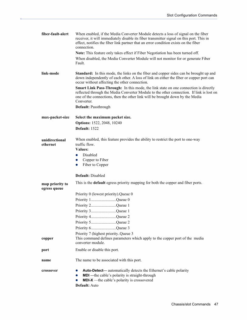
Slot Configuration Commands
fiber-fault-alert When enabled, if the Media Converter Module detects a loss of signal on the fiber receiver, it will immediately disable its fiber transmitter signal on this port. This in effect, notifies the fiber link partner that an error condition exists on the fiber connection.
Note: This feature only takes effect if Fiber Negotiation has been turned off.
When disabled, the Media Converter Module will not monitor for or generate Fiber Fault.
link-mode Standard: In this mode, the links on the fiber and copper sides can be brought up and down independently of each other. A loss of link on either the fiber or copper port can occur without affecting the other connection.
Smart Link Pass-Through: In this mode, the link state on one connection is directly reflected through the Media Converter Module to the other connection. If link is lost on one of the connections, then the other link will be brought down by the Media Converter.
Default: Passthrough
max-packet-size Select the maximum packet size.
Options: 1522, 2048, 10240
Default: 1522
unidirectional ethernet
When enabled, this feature provides the ability to restrict the port to one-way traffic flow.Values:
Disabled Copper to Fiber Fiber to Copper
Default: Disabled
map priority to egress queue
This is the default egress priority mapping for both the copper and fiber ports.
Priority 0 (lowest priority).Queue 0
Priority 1.........................Queue 0
Priority 2.........................Queue 1
Priority 3.........................Queue 1
Priority 4.........................Queue 2
Priority 5.........................Queue 2
Priority 6.........................Queue 3
Priority 7 (highest priority..Queue 3copper This command defines parameters which apply to the copper port of the media
converter module.
port Enable or disable this port.
name The name to be associated with this port.
crossover Auto-Detect— automatically detects the Ethernet’s cable polarity MDI —the cable’s polarity is straight-through MDI-X —the cable’s polarity is crossoveredDefault: Auto
Chassis/slot Commands 47
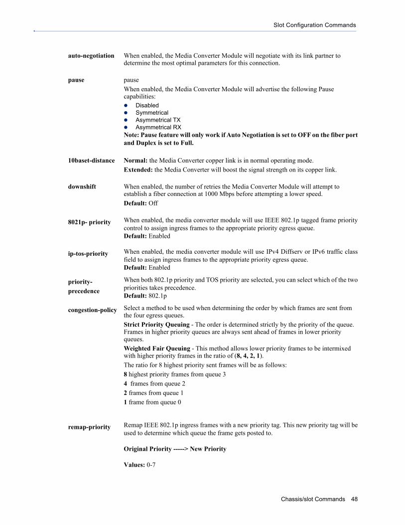
Slot Configuration Commands
auto-negotiation When enabled, the Media Converter Module will negotiate with its link partner to determine the most optimal parameters for this connection.
pause pause
When enabled, the Media Converter Module will advertise the following Pause capabilities: Disabled Symmetrical Asymmetrical TX Asymmetrical RXNote: Pause feature will only work if Auto Negotiation is set to OFF on the fiber portand Duplex is set to Full.
10baset-distance Normal: the Media Converter copper link is in normal operating mode.
Extended: the Media Converter will boost the signal strength on its copper link.
downshift When enabled, the number of retries the Media Converter Module will attempt to establish a fiber connection at 1000 Mbps before attempting a lower speed.
Default: Off
8021p- priority When enabled, the media converter module will use IEEE 802.1p tagged frame prioritycontrol to assign ingress frames to the appropriate priority egress queue.Default: Enabled
ip-tos-priority When enabled, the media converter module will use IPv4 Diffserv or IPv6 traffic classfield to assign ingress frames to the appropriate priority egress queue.Default: Enabled
priority-
precedence
When both 802.1p priority and TOS priority are selected, you can select which of the twopriorities takes precedence.Default: 802.1p
congestion-policy Select a method to be used when determining the order by which frames are sent from the four egress queues.
Strict Priority Queuing - The order is determined strictly by the priority of the queue. Frames in higher priority queues are always sent ahead of frames in lower priority queues.
Weighted Fair Queuing - This method allows lower priority frames to be intermixed with higher priority frames in the ratio of (8, 4, 2, 1).
The ratio for 8 highest priority sent frames will be as follows:
8 highest priority frames from queue 3
4 frames from queue 2
2 frames from queue 1
1 frame from queue 0
remap-priority Remap IEEE 802.1p ingress frames with a new priority tag. This new priority tag will beused to determine which queue the frame gets posted to.
Original Priority -----> New Priority
Values: 0-7
Chassis/slot Commands 48

Slot Configuration Commands
ingress-rate Restricts ingress frames on the copper port.Default: NoneData Options: 64 kbps to 900 mbps
egress-rate Restricts egress frames on the copper port.Default: NoneData Options: 64kbps to 900 mbps
discard-tagged- frames
When enabled, discards all VLAN tagged frames.Default: Off
discard- untagged- frames
When enabled, discards all VLAN untagged frames.Default: Off
sgmii-interface Enable sgmii interface if your SFP supports this interface.
default-vlan-id Specify a default VLAN ID to insert when tagging frames.Default: 1Data Options: 0-4095
default-priority Specify a default VLAN priority to insert when tagging frames.Default: 0Data Options: 0-7
vlan-tagging-
action
Define the VLAN tagging action to take on a egress frame. Normal -Take no action.
Untag - Remove any existing tag.
Tag Insert tag with configured VLAN ID and VLAN priority if original frame is untagged.
Replace tag with configured VLAN ID and VLAN priority if original frame is tagged.
Double tag - Append a tag with configured VLAN ID and VLAN priority.
Default: Normal
fiber This command defines parameters which apply to the fiber port of the media converter module.
port Enable or disable this port.
name The name to be associated with this port.
1-8 characters
auto-negotiation Enabled: The Media Converter Module will negotiate Ethernet parameters on the fiber connection. This will ensure that the most optimal connection parameters will be in effect.
Disabled: The Media Converter Module will negotiate the Ethernet parameter’s with the copper link partner. The parameters used will be determined by the Duplex and Pause settings.
802.1p-priority When enabled, the media converter module will use IEEE 802.1p tagged frame prioritycontrol to assign ingress frames to the appropriate priority egress queue.Default: Enabled
ip-tos-priority When enabled, the media converter module will use IPv4 Diffserv or IPv6 traffic classfield to assign ingress frames to the appropriate priority egress queue.Default: Enabled
Chassis/slot Commands 49

Slot Configuration Commands
priority-
precedence
When both 802.1p priority and TOS priority are selected, you can select which of the twopriorities takes precedence.Default: 802.1p
congestion-policy Select a method to be used when determining the order by which frames are sent from the four egress queues.
Strict Priority Queuing - The order is determined strictly by the priority of the queue. Frames in higher priority queues are always sent ahead of frames in lower priority queues.
Weighted Fair Queuing - This method allows lower priority frames to be intermixed with higher priority frames in the ratio of (8, 4, 2, 1).
The ratio for 8 highest priority sent frames will be as follows:
8 highest priority frames from queue 3
4 frames from queue 2
2 frames from queue 1
1 frame from queue 0
remap-priority Remap IEEE 802.1p ingress frames with a new priority tag. This new priority tag will beused to determine which queue the frame gets posted to.
Original Priority -----> New Priority
Values: 0-7
ingress-rate Restricts ingress frames on the fiber port.Default: NoneData Options: 64 kbps to 900 mbps
egress-rate Restricts egress frames on the fiber port.Default: NoneData Options: 64 kbps to 900 mbps
filter-unknown-
multicast
When enabled, multicast frames with unknown destination addresses are not allowed to egress this port.Default: Disabled
filter-unknown-
unicast
When enabled, unicast frames with unknown destination addresses are not allowed to egress this port.Default: Disabled
default-vlan-id Specify a default VLAN ID to insert when tagging frames.Default: 1Data Options: 0-4095
default-priority Specify a default VLAN priority to insert when tagging frames.Default: 0Data Options: 0-7
Chassis/slot Commands 50

Slot Configuration Commands
Set slot... cm-10g
vlan-tagging-
actions
Define the VLAN tagging action to take on a egress frame. Normal -Take no action.
Untag - Remove any existing tag.
Tag Insert tag with configured VLAN ID and VLAN priority if original frame is untagged.
Replace tag with configured VLAN ID and VLAN priority if original frame is tagged.
Double tag - Append a tag with configured VLAN ID and VLAN priority.
Default: Normal
Description Configure a cm-10g media converter module.User Level AdminSyntax
For STS modules onlyset slot <slot#> cm-10g [fiber-auto-negotiation enabled|disabled]
*For SFP ports set slot <slot#> cm-10g module [fiber-fault-alert disabled|enabled] [link-mode standard|smart-link-passthrough] [name <name>]
set slot <slot#> cm-10g [port 1|2] [edc-mode auto|linear|limiting|cx1][frequency-control enable|disable][channel <1-65535>][name <text>] [port enabled|disabled] [tx-dither-control enable|disabled] [wave-length-control enable|disable wavelength <0-65535>]
* Note: See manufacturers documentation for parameter settings.
*For XFP ports set slot <slot#> cm-10g [port 1|2] [fec enabled|disabled][amplitude-adjustment <-128 - 127>][phase-adjustment <-128 - 127>][frequency-control enable|disable][channel <1-65535>] [name <text>] [port enabled|disabled] [tx-dither-control enable|disabled] [wave-length-control enable|disable][wavelength <0-65535>]
* Note: See manufacturers documentation for parameter settings.
fiber-fault-alert When enabled, if the Media Converter Module detects a loss of signal on the fiber receiver, it will immediately disable its fiber transmitter signal on this port. This in effect, notifies the fiber link partner that an error condition exists on the fiber connection.
Note: This feature only takes effect if Fiber Negotiation has been turned off.
When disabled, the Media Converter Module will not monitor for or generate Fiber Fault.
Chassis/slot Commands 51

Slot Configuration Commands
link-mode Smart Link Pass-Through: In this mode, the link state on one fiber connection is directly reflected through the Media Converter Module to the other fiber connection. If link is lost on one of the fiber connections, then the other fiber link will be brought down by the Media Converter.
Standard: In this mode, each fiber link can be brought up and down independently of each other. A loss of signal on either fiber connection can occur without affecting the other fiber connection.
Default: Smart Link Pass-Through
port Select the port to configure.
Values: 1 or 2
edc-mode Settings: Auto, linear, limiting, CX1Default: Auto
* Note: See manufacturers documentation for parameter settings.
frequency-control Settings:
Channel number 1-65535
* Note See manufacturers documentation for parameter settings
name The name to be associated with this port.
Values: 0-63 characters
tx-dither-control Enable or DisableDefault: Disable
* Note: See manufacturers documentation for parameter settings.
wavelength-control Enable or Disble
Channel number: 0-65535
* Note See manufacturers documentation for parameter settings
name The name to be associated with this port.
Values: 0-63 characters
port Enable or disable this port.
fec Enable or DisableSettings:Amplitude Adjustment: -128 to 127Phase Adjustment: -128 to 127Default: Disabled
* Note: See manufacturers documentation for parameter settings.
fiber-auto-
negotiation
When enabled, the Media Converter Module will negotiate with its link partner to deter-mine the most optimal parameters for this connection. This applies to 1000 SFP modulesonly.Default: Enabled
Chassis/slot Commands 52

Slot Configuration Commands
Set slot... cm-10gt
Description Configure a cm-10gt media converter module.User Level AdminSyntax *For SFP ports
set slot <slot#> cm-10g module [fiber-fault-alert disabled|enabled] [link-mode standard|smart-link-passthrough] [name <name>]
set slot <slot#> cm-10g [port 1|2] [edc-mode auto|linear|limiting|cx1][*frequency-control enable <channel 1-65535>|disable] [name <text>] [port enabled|disabled] [*tx-dither-control enable mode enabled|disabled] [*wave-length-control enabled <wavelength 0-65535>|disable]
* Note: See manufacturers documentation for parameter settings.
*For XFP ports set slot <slot#> cm-10g [port 1|2] [fec enabled|disabled][amplitude-adjustment <-128 - 127>][phase-adjustment <-128 - 127>][frequency-control enable channel <1-65535>|disable [name <text>] [port enabled|disabled] [*tx-dither-control enable mode enabled|disabled] [*wave-length-control enabled <wavelength 0-65535>|disable]
* Note: See manufacturers documentation for parameter settings.
*For copper Ethernet only set slot <slot#> cm-10gt port 2 duplex [half|auto] energy-efficient-ethernet [name <text>][enabled|disabled] pause [disabled|symmetrical|asymmetrical-tx|asymmetrical-rx][port enabled|disabled]
fiber-fault-alert When enabled, if the Media Converter Module detects a loss of signal on the fiber receiver, it will immediately disable its fiber transmitter signal on this port. This in effect, notifies the fiber link partner that an error condition exists on the fiber connection.
Note: This feature only takes effect if Fiber Negotiation has been turned off.
When disabled, the Media Converter Module will not monitor for or generate Fiber Fault.
link-mode Smart Link Pass-Through: In this mode, the link state on one fiber connection is directly reflected through the Media Converter Module to the other fiber connection. If link is lost on one of the fiber connections, then the other fiber link will be brought down by the Media Converter.
Standard: In this mode, each fiber link can be brought up and down independently of each other. A loss of signal on either fiber connection can occur without affecting the other fiber connection.
Default: Smart Link Pass-Through
port Select the port to configure.
Values: 1 or 2
Chassis/slot Commands 53

Slot Configuration Commands
edc-mode Settings: Auto, linear, limiting, CX1Default: Auto
* Note: See manufacturers documentation for parameter settings.
frequency-control Enable or Disable
Channel number: 1-65535
* Note See manufacturers documentation for parameter settings
name The name to be associated with this module.
Values: 0-63 characters
tx-dither-control Enable or Disable Default: Disable* Note: See manufacturers documentation for parameter settings.
wavelength-control Channel number; 0-65535
* Note See manufacturers documentation for parameter settings
name The name to be associated with this port.
Values: 0-8 characters
port Enable or disable this port.
fec Settings:Amplitude Adjustment: -128 to 127Phase Adjustment: -128 to 127Default: Disabled
* Note: See manufacturers documentation for parameter settings.
duplex The following selections are available:
Duplex: Auto, Half
Default: Auto
This duplex configuration parameter will only be used for 1 gigabit SPF modules. For 10 gigabit modules, full duplex will always be advertised
energy-efficient-
ethernet
Enabled: When enabled, the media converter module will auto negotiate EEE with theattached EEE compliant devices/servers.Disabled: The media converter module will not auto negotiate EEE with attached theEEE compliant devices/servers.Default: Enabled
pause The Media Converter Module can advertise the following Pause capabilities: Symmetrical Asymmetrical TX Asymmetrical RXNote: 1 Gigabit modules must have auto negotiation turned off on the fiber side in orderfor Pause to be advertised on the copper side.
Default: Asymmetrical RX
Chassis/slot Commands 54

Slot Configuration Commands
Set slot... cm-4gpt
fiber-auto-
negotiation
When enabled, the Media Converter Module will negotiate with its link partner to deter-mine the most optimal parameters for this connection. This applies to 1000 SFP modulesonly.Default: Enabled
Description Configure a cm-4gpt media converter module.User Level AdminSyntax set slot <slot#> cm-4gpt [port<1|2>[port enabled|disabled][name
<text>]Set slot <slot#> cm-4gpt [module][fiber-fault-alert disabled|enabled] [Link-mode standard|smart-link-passthrough][name <text>][rate-select low|high]
port Select the port to configure.
Values: 1 or 2
port Enable or disable this port.
name The name to be associated with this port.
Values: 0-8 characters
fiber-fault-alert Enabled: If the media converter module detects a loss of fiber signal on its fiber receiver, it will disable its fiber transmitter on the same SFP. This, in effect, notifies the fiber link partner that an error condition exists on the fiber connection.
Disabled: The module will take no action when a loss of signal is detected
Default: Disabled.
link-mode Smart Link Pass-Through: In this mode, the fiber link state on one fiber connection is directly reflected through the media converter module to the other fiber connection. Since this media converter is protocol independent, it monitors the Signal Detect indicator from the SFP and reflects this on the TX port of the other SFP by turning off the transmitter, When the signal (Link) get restored and Signal Detect becomes active, the affected transmitter will get re-enabled.
Standard Mode: In Standard Mode the media converter module will monitor the fiber link in the same manner. If the Signal Detect goes down the media converter module will out a 25MHz signal on the TX port of the other SFP.
Default: Smart Link Pass-Through
name The name to be associated with this module.
Values: 0-63 characters
rate-select High Speed: When a multi-rate SFP is inserted, it is enabled for the higher speed of operation.
Low Speed: When a multi-rate SFP is inserted, it is enabled for the slower speed of operation.
Default: High
Chassis/slot Commands 55

Slot Configuration Commands
Set slot... ex
Description Configure a ex media converter module.User Level AdminSyntax set slot <slot #> ex module [interlink-fault-feedback
enabled|disabled][link-mode standard|smart-link-passthrough][map-priority-to-egress-queue <0-7> <0-3>[unidirectional-ethernet disabled|ethernet-to-vdsl|vdsl-to-ethernet]
set slot <slot #> ex ethernet [10baset-distance normal|extended] 8021p-priority enabled|disabled][auto-negotiation enabled[advertise <10-full|10-half|100-full|100-half|all>|disabled][congestion-policy strict-queueing|weighted queueing][crossover auto|mdi|mdi-x][default-priority <0-7>][default-vlan-id <0-4095>][discard-tagged-frames enable|disabled][discard untagged-frames enabled|disabled][downshift <0-8>][egress-rate-limit none|64kbps|128kbps|192kbps|256kbps|320kbps|384kbps|512kbps|768kbps|1mbps|2mbps|3mbps|4mbps|5mbps|6mbps|7mbps|8mbps|9mbps|10mbps|20mbps|30mbps|40mbps|50mbps|60mbps|70mbps|80mbps|90mbps][egress-rate-limit none|64kbps|128kbps|192kbps|256kbps|320kbps|384kbps|512kbps|768kbps|1mbps|2mbps|3mbps|4mbps|5mbps|6mbps|7mbps|8mbps|9mbps|10mbps|20mbps|30mbps|40mbps|50mbps|60mbps|70mbps|80mbps|90mbps][filter-unknown-multicast enabled|disabled][filter-unknown-unicast enable|disable][ingress-rate-limit none|64kbps|128kbps|192kbps|256kbps|320kbps|384kbps|512kbps|768kbps|1mbps|2mbps|3mbps|4mbps|5mbps|6mbps|7mbps|8mbps|9mbps|10mbps|20mbps|30mbps|40mbps|50mbps|60mbps|70mbps|80mbps|90mbps][ip-tos-priority enabled|disabled][name <text>][pause disabled|symmetrical|asymmetrical-tx|asymmetrical-rx][port enabled|disabled][priority-precendence] 8021p|ip-tos][remap-priority <0-7>][vlan-tagging-action none|untag|tag|double-tag]set slot <slot #> ex vdsl [8021p-priority enabled|disabled][congestion-policy strict-queueing|weighted queueing][default-priority <0-7>][default-vlan-id <0-4095>][discard-tagged-frames enable|disabled][discard untagged-frames enabled|disabled][egress-rate-limit none|64kbps|128kbps|192kbps|256kbps|320kbps|384kbps|512kbps|768kbps|1mbps|2mbps|3mbps|4mbps|5mbps|6mbps|7mbps|8mbps|9mbps|10mbps|20mbps|30mbps
|40mbps|50mbps|60mbps|70mbps|80mbps|90mbps][egress-rate-limit none|64kbps|128kbps|192kbps|256kbps|320kbps|384kbps|512kbps|768kbps|1mbps|2mbps|3mbps|4mbps|5mbps|6mbps|7mbps|8mbps|9mbps|10mbps|20mbps|30mbps|40mbps|50mbps|60mbps|70mbps|80mbps|90mbps] [fast-mode disabled|enabled][filter-unknown-multicast enabled|disabled][filter-unknown-unicast enable|disable][ingress-rate-limit none|64kbps|128kbps|192kbps|256kbps|320kbps|384kbps|512kbps|768kbps|1mbps|2mbps|3mbps|4mbps|5mbps|6mbps|7mbps|8mbps|9mbps|10mbps|20mbps|30mbps|40mbps|50mbps|60mbps|70mbps|80mbps|90mbps] [ip-tos-priority enabled|disabled]low-bandwidth-alarm downstream|upstream <0-90000>][name <text>][over-ride-profile downstream|upstream [bitswapping <enable|disabled>]
Chassis/slot Commands 56

Slot Configuration Commands
[max-datarate <128-101064>] [max-interleave-delay <0-16>][min-datarate <128-101064>][min-inp <1-18>][signal-to-noise-ratio <30-240>][port enabled|disabled][priority-precedence 8021p|ip-tos][profile-type [auto <rate high-speed|long-range> <symmetry asymmetric|symmetric>]|manual <1-33>][remap-priority <0-7> <0-7>][role auto|local|remote] [vlan-tagging-action none|untag|tag|double-tag]
module This command defines parameters which apply to the whole media converter module.
interlink-fault-feedback
In this mode, the Ethernet Link will reflect the VDSL status, if the VDSL link is down the Ethernet Link will be down. If the VDSL link is up the Ethernet Link will be up.
When Interlink Fault Feedback is disabled, the status of the VDSL interface will not be passed to its Ethernet interface.
Default: Disabled.
link-mode Standard: In this mode, the Ethernet Extender module will not pass the state of the Ethernet interface across the Line connection to its peer. A loss on the Ethernet interface can occur without affecting the peer connection.
Smart-Link-Passthrough: In this mode, the Ethernet Extender module will keep the Ethernet interface in a down state until the VDSL line comes up. The Ethernet link will only be brought up if the remote Ethernet Extender has an Ethernet link up.
Default: standard
Map Priority to Egress Queue
This is the default egress priority mapping for both the copper and fiber ports.
Priority 0 (lowest priority).Queue 0
Priority 1.........................Queue 0
Priority 2.........................Queue 1
Priority 3.........................Queue 1
Priority 4.........................Queue 2
Priority 5.........................Queue 2
Priority 6.........................Queue 3
Priority 7 (highest priority).Queue 3
Unidirectional Ethernet
When enabled, this feature provides the ability to restrict the port to one-way traffic flow.Values:
Disabled Ethernet to VDSL VDSL to Ethernet
Default: Disabled
ethernet This command defines parameters which apply to the ethernet port of the media converter module.
These parameters apply to the Ethernet interface on this module.10baset-distance Normal: the Media Converter copper link is in normal operating mode.
Extended: the Media Converter will boost the signal strength on its copper link.
Chassis/slot Commands 57

Slot Configuration Commands
8021p- priority When enabled, the media converter module will use IEEE 802.1p tagged frame prioritycontrol to assign ingress frames to the appropriate priority egress queue.Default: Enabled
auto-negotiation Enabled: Advertise on the copper link one of the following: 10-full, 10-half, 100-full, 100-half, or all.
Disabled: Do not advertise on the copper link.
congestion-policy Select a method to be used when determining the order by which frames are sent from the four egress queues.
Strict Priority Queuing - The order is determined strictly by the priority of the queue. Frames in higher priority queues are always sent ahead of frames in lower priority queues.
Weighted Fair Queuing - This method allows lower priority frames to be intermixed with higher priority frames in the ratio of (8, 4, 2, 1).
The ratio for 8 highest priority sent frames will be as follows:
8 highest priority frames from queue 3
4 frames from queue 2
2 frames from queue 1
1 frame from queue 0
crossover Auto-Detect— automatically detects the Ethernet’s cable polarity MDI —the cable’s polarity is straight-through MDI-X —the cable’s polarity is crossoveredDefault: Auto
default-priority Specify a default VLAN priority to insert when tagging frames.Default: 0Data Options: 0-7
default-vlan-id Specify a default VLAN ID to insert when tagging frames.Default: 1Data Options: 0-4095
discard-tagged- frames
When enabled, discards all VLAN tagged frames.Default: Off
discard- untagged- frames
When enabled, discards all VLAN untagged frames.Default: Off
downshift When enabled, the number of retries the Media Converter Module will attempt to establish a fiber connection at 1000 Mbps before attempting a lower speed.
Default: Off
egress-rate-limit Restricts egress frames on the copper/vdsl port.Default: NoneData Options: 64 kbps to 90 Mbps
fast-mode Fast mode reduces frame latency when using shorter cable distances.
Default: Disabled
Note: Using InterLink override values for upstream and downstream SNR and/or INP values may disable Fast mode.
Chassis/slot Commands 58

Slot Configuration Commands
filter-unknown-
multicast
When enabled, multicast frames with unknown destination addresses are not allowed to egress this port.Default: Disabled
filter-unknown-
unicast
When enabled, unicast frames with unknown destination addresses are not allowed to egress this port.Default: Disabled
ingress-rate limit Restricts egress frames on the copper/vdsl port.Default: NoneData Options: 64 kbps to 90 Mbps
ip-tos-priority When enabled, the media converter module will use IPv4 Diffserv or IPv6 traffic classfield to assign ingress frames to the appropriate priority egress queue.Default: Enabled
low-bandwidth-
alarm
When the upstream or downstream link is established, the Ethernet Extender module willcheck the low bandwidth value. If the data rate is below the threshold value, an SNMPtrap will be generated.
Values: 0-90000 (0 means off)
name The name to be associated with this port.
Values: 0-8 characters
over-ride-profile Allows you to override advance VDSL settings:
Select upstream or downstream to configure the following:
max-datarate: 128-101064 kbps
max-interleave-delay: 0-16 ms
min-datarate: 128-101064
min-inp: 1-18
signal-to-noise-ratio: 30-240
bitswapping: enabled/disabled
Note: Advanced VDSL settings are valid only for Ethernet Extenders that have been configured with a role of Local
bitswapping As line conditions change, bitswapping allows the modem to swap bits around different channels without retraining as each channel becomes more or less capable. If bitswapping is disabled, the modem will need to retrain in order to adapt to changing line conditions.
Default: Enabled
max-datarate The maximum data rate of the VDSL link
Values: 128 - 101064 kbps
max-interleave-
delay
Interleaving is a method of taking packets, chopping them up into smaller bits and then rearranging them so that once contiguous data is now spaced further apart into a noncontinuous stream. This provides better noise protection but increases latency. Enter the maximum acceptable gap in the data.
Values: 128 - 101064 kbps
min-datarate The minimum data rate of the VDSL link
Values: 128 - 101064 kbps
signal-to-noise-
ratio
The Ethernet Extender module will attempt to maintain the desired SNR value by adjusting line settings. A larger dB number will result in less line errors and a more stable connection, but may result in slower speeds.
Values: 30-240 (3-24 dB)
Chassis/slot Commands 59

Slot Configuration Commands
set slot... cm-10gr
port Enable or disable this port.
priority-
precedence
When both 802.1p priority and TOS priority are selected, you can select which of the twopriorities takes precedence.Default: 802.1p
profile-type When both 802.1p priority and TOS priority are selected, you can select which of the twopriorities takes precedence.Default: 802.1p
auto Select profile type "auto" to select either high speed or long range and symmetry parameter.
manual Select profile type "manual" to select from a profile list. Type ? to see complete list.
Values: 1-33
high-speed In this mode, the VDSL connection will be optimized for maximum attainable speeds.
long-range In this mode, the VDSL connection will be optimized for distance and the achieveable distance will be up to 1 mile (3km).
role If both Ethernet Extenders are configured for Auto mode, a proprietary method of detection is implemented for each attempt to synchronize the local and remote Ethernet Extenders modules. However, it is preferable to set one Ethernet Extender module to local and the other Ethernet Extender module to remote since this may results in slightly faster training times and direct control over their roles.
Local (CO): This Ethernet Extender module is set to local mode of operation.
Remote (CPE): This Ethernet Extender module is set to the Remote mode of operation.
vlan-tagging-
actions
Define the VLAN tagging action to take on a egress frame. Normal -Take no action.
Untag - Remove any existing tag.
Tag Insert tag with configured VLAN ID and VLAN priority if original frame is untagged.
Replace tag with configured VLAN ID and VLAN priority if original frame is tagged.
Double tag - Append a tag with configured VLAN ID and VLAN priority.
Default: Normal
Description Configure a cm-10gr media converter module.User Level AdminSyntax set slot <slot#> cm-10gr module [fiber-fault-alert
disabled|enabled] [link-mode standard|smart-link-passthrough] [latency-mode rate-converting|cut-through] [map-priority-to-egress-queue <0|1|2|3|4|5|6|7> <0|1|2|3|4|5|6|7>] [max-packet-size 1522|2048|10240] [name <text>] [unidirectional-ethernet disabled|port2-to-port1|port1-to-port2]
Chassis/slot Commands 60

Slot Configuration Commands
set slot <slot#> cm-10gr [port 1|2] [8021p-priority enabled|disabled] [congestion-policy strict-queuing|weighted-queuing] [default-priority 0|1|2|3|4|5|6|7] [discard-tagged-frames disable|enable] [discard untagged-frames enable|disable] [egress-rate-limit 64kbps |128kbps |192kbps | 256kbps | 320kbps | 384kbps | 512kbps | 768kbps | 1mbps | 2mbps | 3mbps | 4mbps | 5mbps | 6mbps |7mbps | 8mbps | 9mbps | 10mbps | 20mbps | 30mbps |40mbps | 50mbps | 60mbps| 70mbps | 80mbps | 90mbps| 100mbps |200mbps |300mbps| 400mbps | 500mbps | 600mbps | 700mbps | 800mbps | 900mbps][ingress-rate-limit 64kbps | 128kbps |192kbps | 256kbps | 320kbps | 384kbps | 512kbps | 768kbps | 1mbps | 2mbps | 3mbps | 4mbps | 5mbps | 6mbps |7mbps | 8mbps | 9mbps | 10mbps | 20mbps | 30mbps |4 0mbps | 50mbps | 60mbps| 70mbps | 80mbps | 90mbps| 100mbps | 200mbps | 300mbps| 400mbps | 500mbps | 600mbps | 700mbps | 800mbps | 900mbps] [fiber-auto-negotiation enabled|disabled] [filter-unknown-multicast enable|disable] [filter unknown unicasts enable|disable] [ip-tos-priority enabled|disabled] [name <text>] [pause disable|symmetrical|asymmetrical-tx|asymetrical-rx] [port enabled|disabled] [priority-precedence 8021p|ip-tos] [remap priority <0|1|2|3|4|5|6|7> <0|1|2|3|4|5|6|7>][sgmii enabled|disabled] [*tx-dither-control enable mode enabled|disabled] [*wave-length-control enabled <wavelength 0-65535>|disable] [vlan-tagging-action none|untag|tag|double-tag]
* Note: See manufacturers documentation for parameter settings
module This command defines parameters which apply to the whole media converter module.
fiber-fault-alert When enabled, if the Media Converter Module detects a loss of signal on the fiber receiver, it will immediately disable its fiber transmitter signal on this port. This in effect, notifies the fiber link partner that an error condition exists on the fiber connection.
Note: This feature only takes effect if Fiber Negotiation has been turned off.
When disabled, the Media Converter Module will not monitor for or generate Fiber Fault.
link-mode Smart Link Pass-Through: In this mode, the link state on one fiber connection is directly reflected through the Media Converter Module to the other fiber connection. If link is lost on one of the fiber connections, then the other fiber link will be brought down by the Media Converter.
Standard: In this mode, each fiber link can be brought up and down independently of each other. A loss of signal on either fiber connection can occur without affecting the other fiber connection.
Default: Smart Link Pass-Through
latency Rate Converting: Both ports can operate at the same or different speeds.
Cut Through: Both ports need to be the same speed and in full duplex mode. Energy Efficient Ethernet must be disabled.
Note: Other configurable features may not be enabled in cut-through mode.
Default: Rate Converting
Chassis/slot Commands 61

Slot Configuration Commands
max-packet-size Select the maximum packet size.
Options: 1522, 2048, 10240
Default: 1522
map priority to egress queue
This is the default egress priority mapping for both fiber ports.
Priority 0 (lowest priority).Queue 0
Priority 1.........................Queue 0
Priority 2.........................Queue 1
Priority 3.........................Queue 1
Priority 4.........................Queue 2
Priority 5.........................Queue 2
Priority 6.........................Queue 3
Priority 7 (highest priority).Queue 3
unidirectional ethernet
When enabled, this feature provides the ability to restrict the port to one-way traffic flow.Values:
Disabled Port 2 to Port 1 Port 1 to Port 2
Default: Disabled
8021p-priority When enabled, the media converter module will use IEEE 802.1p tagged frame prioritycontrol to assign ingress frames to the appropriate priority egress queue.Default: Enabled
congestion-policy Select a method to be used when determining the order by which frames are sent from the four egress queues.
Strict Priority Queuing - The order is determined strictly by the priority of the queue. Frames in higher priority queues are always sent ahead of frames in lower priority queues.
Weighted Queuing - This method allows lower priority frames to be intermixed with higher priority frames in the ratio of (8, 4, 2, 1).
The ratio for 8 highest priority sent frames will be as follows:
8 highest priority frames from queue 3
4 frames from queue 2
2 frames from queue 1
1 frame from queue 0
default-priority Specify a default VLAN priority to insert when tagging frames.Default: 0Data Options: 0-7
default-vlan-id Specify a default VLAN ID to insert when tagging frames.Default: 1Data Options: 0-4095
discard-tagged- frames
When enabled, discards all VLAN tagged frames.Default: Off
Chassis/slot Commands 62

Slot Configuration Commands
discard- untagged- frames
When enabled, discards all VLAN untagged frames.Default: Off
egress-rate-limit Restricts egress frames on the fiber port.Default: NoneData Options: 64 kbps to 900 Mbps
ingress-rate-limit Restricts egress frames on the fiber port.Default: NoneData Options: 64 kbps to 900 Mbps
filter-unknown-
multicast
When enabled, multicast frames with unknown destination addresses are not allowed to egress this port.Default: Disabled
filter-unknown-
unicast
When enabled, unicast frames with unknown destination addresses are not allowed to egress this port.Default: Disabled
ip-tos-
priority
When enabled, the media converter module will use IPv4 Diffserv or IPv6 traffic classfield to assign ingress frames to the appropriate priority egress queue.Default: Enabled
name The name to be associated with this port.
Values: 0-8 characters
pause When enabled, the Media Converter Module will advertise the following Pause capabilities: Disabled Symmetrical Asymmetrical TX Asymmetrical RXNote: Pause feature will only work if Auto Negotiation is set to OFF on the fiber portand Duplex is set to Full.
port Enable or disable this port.
priority- precedence
When both 802.1p priority and TOS priority are selected, you can select which of the twopriorities takes precedence.Default: 802.1p
remap-priority Remap IEEE 802.1p ingress frames with a new priority tag. This new priority tag will beused to determine which queue the frame gets posted to.
Original Priority -----> New Priority
Values: 0-7
sgmii Enable sgmii interface if your SFP supports this interface.
tx-dither-control Enable or DisableDefault: Disable
* Note: See manufacturers documentation for parameter settings.
Chassis/slot Commands 63

Slot Configuration Commands
vlan-tagging-
actions
Define the VLAN tagging action to take on an egress frame. Normal -Take no action.
Untag - Remove any existing tag.
Tag Insert tag with configured VLAN ID and VLAN priority if original frame is untagged.
Replace tag with configured VLAN ID and VLAN priority if original frame is tagged.
Double tag - Append a tag with configured VLAN ID and VLAN priority.
Default: Normal
wavelength-control Enable or Disable
Channel number: 0-65535
* Note See manufacturers documentation for parameter settings
Chassis/slot Commands 64

Slot Configuration Commands
set slot... cm-10grtDescription Configure a cm-10grt media converter module.User Level AdminSyntax set slot <slot#> cm-10grt module [fiber-fault-alert
disabled|enabled] [link-mode standard|smart-link-passthrough] [name <text>] [latency-mode rate-converting|cut-through] [max-packet-size 1522|2048|10240] map-priority-to-egress-queue 0|1|2|3|4|5|6|7] [1|2|3|4|5|6|7] [unidirectional-ethernet disabled|copper-to-fiber|fiber-to-copper]
*For SFP port
set slot <slot#> cm-10grt [port 1|2] [8021p-priority enabled|disabled] [congestion-policy strict-queuing|weighted-queuing] [default-priority 0|1|2|3|4|5|6|7] [discard-tagged-frames disable|enable] [discard untagged-frames enable|disable][egress-rate-limit 64kbps|128kbps|192|kbps|256kbps|320kbps|384kbps|512kbps|768kbps|1mbps|2mbps|3mbps|4mbps|5mbps|6mbps|7mbps|8mbps|9mbps|10mbps|20mbps|30mbps|40mbps|50mbps|60mbps|70mbps|80mbps|90mbps|100mbps|200mbps|300mbps|400mbps|500mbps|600mbps|700mbps|800mbps|900mbps] [ingress-rate-limit 64kbps|128kbps|192|kbps|256kbps|320kbps|384kbps|512kbps|768kbps|1mbps|2mbps|3mbps|4mbps|5mbps|6mbps|7mbps|8mbps|9mbps|10mbps |20mbps|30mbps|40mbps|50mbps|60mbps|70mbps|80mbps|90mbps|100mbps|200mbps|300mbps|400mbps|500mbps|600mbps|700mbps|800mbps|900mbps] [fiber-auto-negotiation enabled| [disabled <speed 10|100> duplex<half|full>] [filter-unknown-multicast enable|disable] [filter unknown unicasts enable||disable] [ip-tos-priority enabled|disabled] [name <text>] [pause disable|symmetrical|asymmetrical-tx|asymetrical-rx] [port enabled|disabled] [priority-precedence 8021p|ip-tos] [remap priority <0|1|2|3|4|5|6|7> <0|1|2|3|4|5|6|7>] [sgmii enabled|disabled] [*tx-dither-control enable mode enabled|disabled] [*wave-length-control enabled <wavelength 0-65535>|disable] [vlan-tagging-action none|untag|tag|double-tag]
For copper Ethernetset slot <slot#> cm-10grt module [fiber-fault-alert disabled|enabled] [link-mode standard|smart-link-passthrough] [name <text>] [latency-mode rate-converting|cut-through] [max-packet-size 1522|2048|10240] map-priority-to-egress-queue 0|1|2|3|4|5|6|7] [1|2|3|4|5|6|7]unidirectional-ethernet disabled|copper-to-fiber|fiber-to-copper]
set slot <slot#> cm-10gtr port 2 [25gbaset-distance normal|extended][802.1p-priority enable|disable] [congestion-policy strict-queuing|weighted-queuing] [crossover auto| mdi|mdix] [default-priority 0|1|2|3|4|5|6|7] [default-vlan <0-4095> [discard-tagged-frames enable|disable] [discard-untagged-frames enable|disable] [downshift <0-8>] [egress-rate-limit 64kbps|128kbps|192|kbps|256kbps|320kbps|384kbps|512kbps|768kbps|1mbps|2mbps|3mbps|4mbps|5mbps|6mbps|7mbps|8mbps|9mbps|10mbps|20mbps|30mbps|40mbps|50mbps|60mbps|70mbps|80mbps|90mbps|100mbps|200mbps|300mbps|400mbps|500mbps|600mbps|700mbps|800mbps|900mbps] [energy-efficient-ethernet enable|disable] [filter-unknown-multicast enabled|disabled] filter-unknown-unicast enabled|disabled] [ingress 64kbps|128kbps|192|kbps|256kbps|320kbps|384kbps|512kbps|768kbps|1mbps|2mbps|3mbps|4mbps|5mbps|6mbps|7mbps|8mbps|9mbps|10mbps|20mbps|30mbps|40mbps|50mbps|60mbps|70mbps|80mbps|90mbps|100mbps|200mbps|300mbps|400mbps|500mbps|600mbps|700mbps|800mbps|900mbps]
Chassis/slot Commands 65

Slot Configuration Commands
[energy-efficient-ethernet enable|disable] [filter-unknown-multicast enabled|disabled] filter-unknown-unicast enabled|disabled] [ingress 64kbps|128kbps|192|kbps|256kbps|320kbps|384kbps|512kbps|768kbps|1mbps|2mbps|3mbps|4mbps|5mbps|6mbps|7mbps|8mbps|9mbps|10mbps|20mbps|30mbps|40mbps|50mbps|60mbps|70mbps|80mbps|90mbps|100mbps|200mbps|300mbps|400mbps|500mbps|600mbps|700mbps|800mbps|900mbps] [ip-tos-priority enabled|disabled] [name <text>] [pause disable|symmetrical|asymmetrical-tx|asymetrical-rx] port enabled|disabled] [priority-precedence 8021p|ip-tos] [remap priority <0|1|2|3|4|5|6|7> <0|1|2|3|4|5|6|7>] [vlan-tagging-action none|untag|tag|double-tag]
module This command defines parameters which apply to the whole media converter module.
25gbase-T distance Normal: the Media Converter copper link is in normal operating mode.
Extended: the Media Converter will boost the signal strength on its copper link.
fiber-fault-alert When enabled, if the Media Converter Module detects a loss of signal on the fiber receiver, it will immediately disable its fiber transmitter signal on this port. This in effect, notifies the fiber link partner that an error condition exists on the fiber connection.
Note: This feature only takes effect if Fiber Negotiation has been turned off.
When disabled, the Media Converter Module will not monitor for or generate Fiber Fault.
link-mode Smart Link Pass-Through: In this mode, the link state on one fiber connection is directly reflected through the Media Converter Module to the other fiber connection. If link is lost on one of the fiber connections, then the other fiber link will be brought down by the Media Converter.
Standard: In this mode, each fiber link can be brought up and down independently of each other. A loss of signal on either fiber connection can occur without affecting the other fiber connection.
Default: Smart Link Pass-Through
latency Rate Converting: Both ports can operate at the same or different speeds.
Cut Through: Both ports need to be the same speed and in full duplex mode. Energy Efficient Ethernet must be disabled.
Note: Other configurable features may not be enable in cut-through mode.
Default: Rate Converting
max-packet-size Select the maximum packet size.
Options: 1522, 2048, 10240
Default: 1522
Chassis/slot Commands 66

Slot Configuration Commands
map priority to egress queue
This is the default egress priority mapping for both fiber ports.
Priority 0 (lowest priority).Queue 0
Priority 1.........................Queue 0
Priority 2.........................Queue 1
Priority 3.........................Queue 1
Priority 4.........................Queue 2
Priority 5.........................Queue 2
Priority 6.........................Queue 3
Priority 7 (highest priority).Queue 3
unidirectional ethernet
When enabled, this feature provides the ability to restrict the port to one-way traffic flow.Values:
Disabled Copper to Fiber Fiber to Copper
Default: Disabled
crossover Auto-Detect— automatically detects the Ethernet’s cable polarity MDI —the cable’s polarity is straight-through MDI-X —the cable’s polarity is crossoveredDefault: Auto
downshift When enabled, the number of retries the Media Converter Module will attempt to establish a fiber connection at 1000 Mbps before attempting a lower speed.
Default: Off
8021p-priority When enabled, the media converter module will use IEEE 802.1p tagged frame prioritycontrol to assign ingress frames to the appropriate priority egress queue.Default: Enabled
congestion-policy Select a method to be used when determining the order by which frames are sent from the four egress queues.
Strict Priority Queuing - The order is determined strictly by the priority of the queue. Frames in higher priority queues are always sent ahead of frames in lower priority queues.
Weighted Queuing - This method allows lower priority frames to be intermixed with higher priority frames in the ratio of (8, 4, 2, 1).
The ratio for 8 highest priority sent frames will be as follows:
8 highest priority frames from queue 3
4 frames from queue 2
2 frames from queue 1
1 frame from queue 0
default-priority Specify a default VLAN priority to insert when tagging frames.Data Options: 0-7Default: 0
default-vlan-id Specify a default VLAN ID to insert when tagging frames.Data Options: 0-4095Default: 1
Chassis/slot Commands 67

Slot Configuration Commands
discard-tagged- frames
When enabled, discards all VLAN tagged frames.Default: Off
discard- untagged- frames
When enabled, discards all VLAN untagged frames.Default: Off
egress-rate-limit Restricts egress frames on the fiber port.Default: NoneData Options: 64 kbps to 900 Mbps
ingress-rate-limit Restricts egress frames on the fiber port.Default: NoneData Options: 64 kbps to 900 Mbps
filter-unknown-
multicast
When enabled, multicast frames with unknown destination addresses are not allowed to egress this port.Default: Disabled
filter-unknown-
unicast
When enabled, unicast frames with unknown destination addresses are not allowed to egress this port.Default: Disabled
ip-tos-
priority
When enabled, the media converter module will use IPv4 Diffserv or IPv6 traffic classfield to assign ingress frames to the appropriate priority egress queue.Default: Enabled
name The name to be associated with this port.
Values: 0-8 characters
priority- precedence
When both 802.1p priority and TOS priority are selected, you can select which of the twopriorities takes precedence.Default: 802.1p
remap-priority Remap IEEE 802.1p ingress frames with a new priority tag. This new priority tag will beused to determine which queue the frame gets posted to.
Original Priority -----> New Priority
Values: 0-7
sgmii Enable sgmii interface if your SFP supports this interface.(sfp port 1 only)
vlan-tagging-
actions
Define the VLAN tagging action to take on a egress frame. Normal -Take no action.
Untag - Remove any existing tag.
Tag Insert tag with configured VLAN ID and VLAN priority if original frame is untagged.
Replace tag with configured VLAN ID and VLAN priority if original frame is tagged.
Double tag - Append a tag with configured VLAN ID and VLAN priority.
Default: Normal
port Select the port to configure.
Values: 1 or 2
name The name to be associated with this module.
Values: 0-63 characters
Chassis/slot Commands 68

Slot Configuration Commands
Show slot * command
tx-dither-control Enable/disable tx-dither-controlDefault: Disable
* Note: See manufacturers documentation for parameter settings.
wavelength-control Enable/disable wavelength control
wavelength number: 0-65535
* Note See manufacturers documentation for parameter settings
name The name to be associated with this port.
Values: 0-8 characters
port Enable or disable this port.
energy-efficient-
ethernet
Enabled: When enabled, the media converter module will auto negotiate EEE with theattached EEE compliant devices/servers.Disabled: The media converter module will not auto negotiate EEE with attached theEEE compliant devices/servers.Default: Enabled
pause The Media Converter Module can advertise the following Pause capabilities: Symmetrical Asymmetrical TX Asymmetrical RXNote: 1 Gigabit modules must have auto negotiation turned off on the fiber side in orderfor Pause to be advertised on the copper side.
Default: Asymmetrical RX
auto-negotiation Enabled: The Media Converter Module will negotiate Ethernet parameters on the copper connection. This will ensure that the most optimal connection parameters will be in effect.
Disabled: The Media Converter Module will negotiate the Ethernet parameter’s with the copper link partner. The parameters used will be determined by the Duplex and Pause settings.
See duplex and speed for settings
duplex When auto-negotiation is set to off select duplex for this copper port.
Duplex: Full, Half
speed When auto-negotiation is set to off select speed for this copper port.
Specify the baud rate.
Data Options: 10, 100
fiber-auto-
negotiation
When enabled, the Media Converter Module will negotiate with its link partner to deter-mine the most optimal parameters for this connection. Fiber auto negotiation only for1000mbps SFP’s.Default: Enabled
Description Displays what module is inserted in each slot.User Level Admin, Operator
Chassis/slot Commands 69

Slot Configuration Commands
Show slot # command
Show chassis alerts
Show chassis details
Syntax show slot *
Description Depending on the module inserted information about that specific slot will be displayed.
User Level Admin, OperatorSyntax slow slot <slot #> fiber [config|sfp|statistics] [sfp thresholds]
show slot <slot #> fiber [1|2] configshow slot <slot #> copper [config|statistics]show slot <slot #> port [1|2] [config|xfp|sfp] [xfp|sfp thresholds]show slot <slot #> alerts show slot <slot #> detailsshow slot <slot #> link-testshow slot <slot #> moduleshow slot <slot #> portshow slot <slot #> power scheduleshow slot <slot #> switches
Description Displays the local alert log.User Level Admin, OperatorSyntax show chassis alerts
Description Displays the chassis firmware and serial number info.User Level Admin, OperatorSyntax show chassis details
Chassis/slot Commands 70

User Commands Chapter 44
Commands for active sessionsAdmin
Help
Logout
Menu
Ping
Description Changes a Operator-level user to the Admin user. When you press Enter after you type this command, you will be prompted for the Admin password.
User Level OperatorSyntax admin
Description Displays help on using the command line interface (CLI).User Level Operator, AdminSyntax help
Description Logs the user out from the MCR-MGT Management Module.User Level Operator, AdminSyntax logout
Description Switches from a command line based interface to Menu mode of operation.User Level Operator, AdminSyntax menu
Description This command checks to see if a given host is reachable via an IP message. The specific message used is called a ping.
User Level Operator, AdminSyntax ping [destination] [<packet_size>] [<#_of_packets>]
destination This can be a "hostname" or an "IP address"
The name (DNS resolvable host name) or IP address of the machine you are trying to ping.
packet-size Enter the number of data bytes to be sent. The default is 100 bytes.
#of packets Enter the number of the packets you want to send. The default is 10.
MCR-MGT Management Module CLI Reference Guide 71

Configuring Users
Screen
Set Termtype
Syslog Console
Show Termtype
Version
Configuring Users
Add User
Description Switches from a command line based interface to Menu mode of operation.User Level Operator, AdminSyntax screen
Description Sets the type of terminal being used on the console port.User Level Operator, AdminSyntax set termtype [type]
type Specifies the type of terminal connected to the console port
Dumb
WYSE60
VT100
ANSI
TVI925
IBM3151TE
VT320 (specifically supporting VT320-7)
HP700 (specifically supporting HP700/44)
Description Starts/stops or displays the status of the syslog console.User Level Admin, OperatorSyntax syslog console [start|stop]
syslog console [status]
start
stopStart or stop console logging. When console logging is enabled, syslog messages will be echoed to the console. These messages are filtered based on the level set in the (remote) syslog options.
status Displays the current console logging status (enabled or disabled).
Description Shows the terminal type for the current session.User Level Admin, OperatorSyntax show termtype
Description Displays firmware version and build.User Level Operator, AdminSyntax version
Description Add a new user to the local user database.User Level AdminSyntax add user <username>
User Commands 72

Configuring Users
Delete User
Set User
Show User
username The name of the user, without spaces. When you finish the command and press Enter, you will be prompted to enter and re-enter a password for the user.
Description Deletes a user.User Level AdminSyntax delete user <config_user>
delete-user You can see a list of users that can be deleted by typing delete user ?. You can not delete the admin user.
Description Sets users settings.User Level AdminSyntax set user username [level] [password]
username The name of an existing user in the local user database.level The access that a user is allowed:
Admin—The admin level user has total access to the MCR-MGT Management Module. You can create more than one admin user account but we recommend that you only have one. They can monitor and configure the MCR-MGT Management Module.
Operator—The Operator can fully operate the MCR-MGT Management Module but can not change any configurable parameters.
password The password the user will need to enter to login to the MCR-MGT Management Module. This case-sensitive field accepts a maximum of 16 characters.
Description Shows user configuration settings.User Level Admin, OperatorSyntax show user <configured_user>|.
configured user Show the settings for the specified user.. Show the settings for the current user.
User Commands 73

Network Commands Chapter 55
SNMP CommandsAdd Community
Set SNMP
Description Adds an SNMP community (version 1 and version 2).User Level AdminSyntax add community <community_name> <config-host>|<internet-address>
[none|readonly|readwrite]
community-name SNMP community name>
config- host
internet-addressThe host name or IP address of the SNMP community that will send requests to the MCR-MGT Management Module.
none|readonly|
readwrite
The permission rights for this SNMP community.
Description Configures SNMP settings.User Level AdminSyntax set snmp [contact] [location][readonly user] [readwrite
user][engine-id-suffix]
contact The name and contract information of the person who manages this SMNP node.
location The physical location of the SNMP node.
readonly user (SNMP version 3) Specified user can only view SNMP variables.
readwrite user (SNMP version 3) User that can view and edit SNMP variables.
engine-id-
suffix
This is the engine ID suffix which will be used with V3 traps. It is used to help identify the trap sender to the trap receiver. It is a unique identifier of the SNMP agent in the domain. By default the Engine ID is composed using the serial number of the Management Module which should make it unique. If you wish to assign a different engine ID to this node, use the "custom" keyword followed by the engine ID suffix string. If you want to revert to the default engine ID, use the "default" keyword. When changing the engine ID, the string entered in this field will be combined with other required elements to form the EngineID. It is up to the user to ensure that this will be a unique string.
MCR-MGT Management Module CLI Reference Guide 74

SNMP Commands
Set SNMP V3-Security
Set snmp-trap common
Set snmp-trap entry
Description Configures SNMP settings for the Version 3 read-write, read-only and trap user(s).User Level AdminSyntax set snmp v3-security [usertype] [security-level] [auth-algorithm]
[auth-password] [privacy-algorithm] [privacy-password]usertype Specify the security parameters for each of the "readonly" and "readwrite" user types.
This parameter defines which of the two user types this applies to. Valid options are;
readonly
readwrite
security-level Select the security level for the user. This must match the configuration set up in the SNMP manager.
Data Options:
None—No security is used.
Auth—User authentication is used.
Auth/Priv—User authentication and privacy (encryption) settings are used.
Default: None
auth-algorithm Specify the authentication algorithm that will be used for the user.
Data Options: MD5, SHA
Default: MD5
auth-password If you specify this parameter you will be prompted for the password as well as to re-type the password after you press enter on this command.
privacy-algorithm Specify the encryption algorithm to be used with this user.
Data Options: DES, AES
Default: DES
privacy-password If you specify this parameter you will be prompted for the password as well as to re-type the password after you press enter on this command.
Description Adds an SNMP host to which trap messages will be sent.User Level AdminSyntax set snmp-trap common [inform-retries] [inform-timeout] [level]
mode]
inform-
retires
This is only used for "Inform" traps. Select the number of times the trap will be sent if no acknowledgement is received. The default is 3.
inform-
timeout
This is only used for "Inform" traps. Select the number of seconds to wait for the acknowledgement of the trap. The default is 1 second.
level Choose the event level that triggers an SNMP trap to be sent.
Data Options: system-level-fault, module-level-fault, persistent-error, one-time-error, significant-event, normal-operation
mode Enable or Disable the sending of traps.
Description Adds an SNMP host to which trap messages will be sent. Up to 4 trap host entries can be defined.
User Level Admin
Network Commands 75

SNMP Commands
Set snmp-trap v3
Syntax set snmp-trap entry [entry#][community][internet-address][mode] [type][udp][version]
entry # Enter the entry number. Valid options are 1 - 4.community The name of the group that devices and management stations running SNMP belong to.
This only applies to SNMP version 1 and version 2c.
internet-address
The IP address of the SNMP manager that will send requests to the MCR-MGT module. If the address is 0.0.0.0, any SNMP manager matching the Community name configured, can access the MCR-MGT module. If you specify a network address, for example 172.16.0.0, any SNMP manager residing on the 172.16.x.x subnet with a matching Community name can access the MCR-MGT module.
Field Format: IPv4 or IPv6 address
mode Enable or Disable this trap host entry.type This field is ignored for trap host version v1"
Data Options:
Trap - Management module will send traps via a TRAP_PDU or TRAP2-PDU not expecting any response from the specified host.
Inform - Management module will send traps via an INFORM_PDU, expecting a response from the specified host.
Default: Trapudp Enter the UDP port number that the SNMP trap host is listening on for UDP traps.
Default: 162
version Defines the SNMP version of the traps sent to the specified host. If v3 is selected then the SNMP trap v3 user will be used to authenticate the trap with the specified host. Valid options are v1, v2c or v3.
Default: v1
Description Defines the parameters associated with the SNMP trap user for V3 traps.User Level AdminSyntax set snmp-trap v3 [username] [security-level] [auth-algorithm]
[auth-password] [privacy-algorithm] [privacy-password]
username This field identifies the system sending the traps to the host receiving the traps. Same user name is used for all v3 traps sent by this system.
security-level Select the security level for the user. This must match the configuration set up in the SNMP manager.
Data Options:
None—No security is used.
Auth—User authentication is used.
Auth/Priv—User authentication and privacy (encryption) settings are used.
Default: None
auth-algorithm Specify the authentication algorithm that will be used for the user.
Data Options: MD5, SHA
Default: MD5
auth-password If you specify this parameter you will be prompted for the password as well as to re-type the password after you press enter on this command.
Network Commands 76

SNMP Commands
Delete Community
Show SNMP
privacy-algorithm Specify the encryption algorithm to be used with this user.
Data Options: DES, AES
Default: DES
privacy-password If you specify this parameter you will be prompted for the password as well as to re-type the password after you press enter on this command.
Description Deletes an SNMP community (version 1 and version 2).User Level AdminSyntax delete community <config_community_number>
config community number
When you add an SNMP community, it gets assigned to a number. To delete the SNMP community, you need to specify the number of the community that you want to delete. To see which community is assigned to what number, type the show snmp command.
Description Shows SNMP settings, including communities and traps.User Level Admin, OperatorSyntax show snmp
Network Commands 77

Hosts Commands
Hosts Commands
Add Host
Delete Host
Set Host
Show Hosts
Description Adds a host to the MCR-MGT Management Module host table.User Level AdminSyntax add host <hostname> <IP_address>
add host <hostname> fqdn <text>
<ip-address> This can be an IPv4 or IPv6 address
<hostname> The name of the host. This is used only for the MCR-MGT Management Module configuration.
Field Format: Up to 14 characters, no spaces.
fqdn fqdn
When you have DNS defined in the MCR-MGT Management Module, you can enter a DNS resolvable fully qualified domain name (note: FQDN’s are excluded as accessible hosts when IP Filtering is enabled).
Description Deletes a host from the MCR-MGT Management Module host table.User Level AdminSyntax delete host <config_host>
Option <config_host>
You can see a list of hosts that can be deleted by typing delete host?.
Description Modifies a host entry in the MCR-MGT Management Module host table. User Level AdminSyntax set host _default <config_host> <IP_address>
set host <config_host> fqdn <text>
Options <config_host>
The name of the host. This is used only for the MCR-MGT Management Module configuration.
Field Format: Up to 14 characters, no spaces.
<IP_address> Assign a specific IP address and subnet to the MCR-MGT Management Module’s Ethernet inteface.
fqdn When you have DNS defined in the MCR-MGT Management Module, you can enter a DNS resolvable fully qualified domain name (note: FQDN’s are excluded as accessible hosts when IP Filtering is enabled).
Description Shows the MCR-MGT Management Module host table.User Level Operator, AdminSyntax show hosts
Network Commands 78

Hosts Commands
Add Authorized Host
Delete Authorized Host
Set Authorized Host
Show Authorized Hosts
Description Adds a host to the MCR-MGT Management Module authorized host table.User Level AdminSyntax add authorized-host ip-address <IP_address> <description>
add authorized-host mac-address <mac_address> <description>
<IP_address> This can be an IPv4 or IPv6 address
<mac address> The format is aa-bb-cc-dd-ee-ff.
<description> This is a description which will help you identify this host.
Description Deletes a host from the MCR-MGT Management Module authorized host table.User Level AdminSyntax delete authorized-host ip-address <IP_address>
delete authorized-host mac-address <mac_address>
<IP_address> IP address of a host in the table<mac_address> MAC address of a host in the table
Description Enables or Disables the use of the authorized host table. A security feature that when enabled, the Management Module will only accept data from or send data to hosts configured in the Authorized Host Table, Host Table, DNS Servers, SNMP communities, SNMP Traps, LDAP authentication Host IP server address, Email server Host IP address and Bootup files Host IP address. Host IP addresses must be configured with an IP address and not using FQDN.
User Level AdminSyntax set authorized-hosts mode [enabled|disabled]
Description Shows the status of the authorized host feature. Either Enabled or Disabled.User Level Admin, OperatorSyntax show authorized-hosts
Network Commands 79

DNS Commands
DNS Commands
Add DNS
Delete DNS
Show DNS
Description Adds a DNS entry.User Level AdminSyntax add dns <IP_address>
Option <IP_address>
You can specify the IP addresses for up to four DNS (Domain Name Servers) hosts in your network.
Description Deletes a DNS entry.User Level AdminSyntax delete dns <config_dns_addr>
Option <config_dns_addr>
You can view a list of configured DNS server IP addresses to choose from by typing delete dns?.
Description Shows all DNS entries, even those supplied by DHCP/BOOTP when applicable.User Level Admin, OperatorSyntax show dns
Network Commands 80

Gateway Commands
Gateway Commands
Add Gateway
Delete Gateway
Set Gateway
Description Adds a gateway. You can configure up to twenty gateways.User Level AdminSyntax add gateway <config_host> default
add gateway <config_host> host <dest_IP_addr>
add gateway <config_host> network <dest_IPv4_addr>|<dest_IPv6_addr> [<subnet_bits_0-32>|<prefix_bits_0-128>]
add gateway specify-gateway ipv6tunnel <tunnel_name> default|host <dest_IP_addr>|network <dest_IPv4_addr>|<dest_IPv6_addr> [<subnet_bits_0-32>|<prefix_bits_0-128>]
Options <config_host>
Select this option when a host is being used at the route gateway.
Default: Enabled, None
default|host|network
ipv6tunnel <tunnel_name>
<dest_IP_addr>
<subnet_bits>|<prefix_bits>
When the route is a Network route, you must specify the network’s subnet mask.
Description Deletes a gateway.User Level AdminSyntax delete gateway <config_gateway_host>
Option <config_gateway_host>
You can view the configured gateways that can be deleted by typing delete gateway?.
Description Modifies an existing gateway.User Level AdminSyntax set gateway <config_gateway_host> default
set gateway <config_gateway_host> host <destination_ip>
set gateway <config_gateway_host> network <dest_IPv4_addr>|<dest_IPv6_address> <prefixbits_mask>
Options <config_gateway_host>
You can view the configured gateways that can be deleted by typing delete gateway?.
default|host|network
Network Commands 81

Gateway Commands
Show Gateways
<destination_ip>
<prefixbits_mask>
Description Shows configured gateways.User Level Operator, AdminSyntax show gateways
Network Commands 82

Logging Commands
Logging Commands
Set Syslog
Show Syslog
Set event-log
Description Configures the system syslog.User Level AdminSyntax set syslog
[level emergency|alert|critical|error|warning|notice|info|debug] [primary-host <config_host>] [secondary-host <config_host>]
level Set level for syslog.
primary-host Sets the primary host address for syslog messages to be sent to.secondary-host Sets the secondary host address for syslog messages to be sent
to.
Description Shows the syslog settings.User Level Admin, OperatorSyntax show syslog
Description Configures the local system log.User Level AdminSyntax set event-log [level] [mode]
level Choose the alert level that will trigger a notification to be sent to the local log.
Data Options:
System-level Fault
Module Level Fault
Persistent Error
One-time error
Significant Event
Normal Operation.
The level selected is the minimum trigger level with the "Normal Operation" being the least severe and "System-level Fault" being the most severe. The level selected will include alerts of that level and all more severe levels above it.
Default: Normal Operation
mode Enable or disable the local event log.
Network Commands 83

IPv6 Tunnels
IPv6 Tunnels
Add IPv6tunnel
Set IPv6tunnel
Show IPv6tunnel
Delete IPv6tunnel
Description Adds a new IPv6 tunnel.User Level AdminSyntax add ipv6tunnel <tunnel_name>
tunnel name Adds an IPv6 tunnel.
Description Configures the specified IPv6 tunnel.User Level AdminSyntax set ipv6tunnel <config-tunnel-name> [mode manual|teredo|6to4]
[gateway <interface>] [remote-host <config_host>]
config- tunnel- name
Specify a IPv6 tunnel name.
mode The method or protocol that is used to create the IPv6 tunnel. Manual—When enabled, the MCR-MGT Management Module will manually create
the IPv6 tunnel to the specified Remote Host through the specified Interface. 6to4—When enabled, the MCR-MGT Management Module will broadcast to the
multicast address 192.88.99.1 through the specified Interface. When the closest 6to4 router responds, it will create the IPv6 tunnel, encapsulating and decapsulating IPv6 traffic sent to and from the MCR-MGT Management Module.
Teredo—When enabled, the Teredo protocol encapsulates the IPv6 packet as an IPv4 UDP message, allowing it to pass through most network address translator (NAT) boxes and create an IPv6 tunnel to the specified Remote Host (a Teredo server) through the specified Interface.
Default: Manual
gateway The interface that the MCR-MGT Management Module is going to use to access the Remote Host.
Default: Ethernet 1
remote-host The IPv4 host that can access the IPv6 network when the Mode is Manual.
The Teredo server when the Mode is Teredo.
Default: None
Description Shows the specified IPv6 tunnel settings.User Level AdminSyntax show ipv6tunnel <config-tunnel-name>
Description Controls the state of all IPsec tunnels.User Level AdminSyntax delete ipv6tunnel <config-tunnel-name>config tunnel name <config-tunnel-name>
Deletes an IPv6 tunnel. If a tunnel is associated with a route, it cannot be deleted until the route is either changed or deleted.
Network Commands 84

Administration Commands Chapter 66
Administration Commands
Reboot
Reset Factory
Set Firmware auto-update
Show Firmware auto-update
Save
Set Bootup
Description Reboots the MCR-MGT Management Module. You will be prompted to save configuration to FLASH, if there have been unsaved configuration changes.
User Level Admin, OperatorSyntax reboot
Description Resets the MCR-MGT Management Module to the factory configuration. User Level AdminSyntax reset factory
Description Automatically updates all managed Media Converter Modules with the bundled firmware.
User Level AdminSyntax set firmware auto-update [enabled | disabled]
Description Shows the status of the update Media Converter Modules firmware feature. Shows banded version firmware for each managed Media Converter Module.
User Level AdminSyntax show firmware auto-update
Description Saves the configuration to FLASH. User Level AdminSyntax save
Description Specifies the TFTP host and pathname for files to be loaded after a MCR-MGT Management Module reboot.
User Level Admin
Administration Commands 85
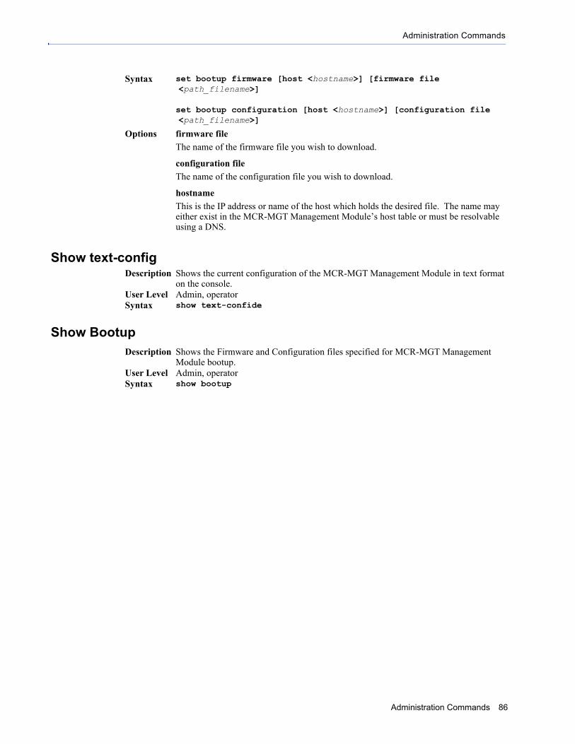
Administration Commands
Show text-config
Show Bootup
Syntax set bootup firmware [host <hostname>] [firmware file <path_filename>]
set bootup configuration [host <hostname>] [configuration file <path_filename>]
Options firmware file
The name of the firmware file you wish to download.
configuration file
The name of the configuration file you wish to download.
hostname
This is the IP address or name of the host which holds the desired file. The name may either exist in the MCR-MGT Management Module’s host table or must be resolvable using a DNS.
Description Shows the current configuration of the MCR-MGT Management Module in text format on the console.
User Level Admin, operatorSyntax show text-confide
Description Shows the Firmware and Configuration files specified for MCR-MGT Management Module bootup.
User Level Admin, operatorSyntax show bootup
Administration Commands 86

TFTP File Transfer Commands
TFTP File Transfer Commands
Netload configuration and firmware
Netsave configuration
Note: To download firmware, you will be asked to agree with Perle’s Licensing Agreement and Privacy Policy. Type y to agree that you have read and understand these agreements. The firmware download will then continue.
Description Transfers a file from a remote host to the MCR-MGT Management Module using the TFTP protocol.
User Level AdminSyntax netload text-config|firmware|configuration <hostname/IP_address>
<filename>
Options text-config
Specify this option if you are uploading a text-based configuration file to the MCR-MGT Management Module from a TFTP server.
firmware
Specifies that you are going to download a new firmware file to the MCR-MGT Management Module.
configuration
Specifies that you are going to download a new configuration file to the MCR-MGT Management Module.
<hostname/IP_address>
The IP address or host name where the file you are downloading to the MCR-MGT Management Module resides. If you are using a host name, it must be resolved in either the MCR-MGT Management Module’s Host Table or a DNS server.
<filename>
The complete path and file name of the file you are downloading to the MCR-MGT Management Module (this path should be relative to the default path of your TFTP server, which may or may not allow drive letters).
Description Transfers a file from the MCR-MGT Management Module to a remote host using the TFTP protocol.
User Level AdminSyntax netsave configuration|diagnostic-file|serialt-buf|text-config
<hostname/IP_address> <filename>
Options configuration
Specifies that you are going to upload a configuration file from the MCR-MGT Management Module to the specified host or IP address.
diagnostic-file
Specifies that you are going to upload a diagnostics file from the MCR-MGT Management Module to the specified host or IP address.
serialt-buf
Specifies that you are going to upload the contents of the serial trace buffer.
text-config
Specifies that you are going to upload the configuration in text format.
Administration Commands 87

TFTP File Transfer Commands
<hostname/IP_address>
The IP address or host name for where the file you are uploading from the MCR-MGT Management Module is going. If you are using a host name, it must be resolved in either the MCR-MGT Management Module’s Host Table or a DNS server.
<filename>
The complete path and file name for the file you are uploading from the MCR-MGT Management Module (this path should be relative to the default path of your TFTP server, which may or may not allow drive letters).
Administration Commands 88

Keys and Certificates Commands
Keys and Certificates Commands
Netload keys
Netsave keys
Description Loads certificates and keys into the MCR-MGT Management Module using TFTP.User Level AdminSyntax netload ssl certificate|private-key <hostname/IP_address>
<filename>
netload ssh-server user <config_user> public-key ssh-2 rsa|dsa <hostname/IP_address> <filename>
Options ssl certificate|private-key|ca-list
If you are using the secure version of the WebManager (HTTPS), or LDAP authentication with TLS, then you need to download the SSL/TLS private key and CA list to make a secure connection.
public-key ssh-2
Specify ssh-2 when you are using SSH version 2.
rsa|dsa
When downloading keys to the MCR-MGT Management Module, specify the authentication method used by the key.
ssh-server user
The user that the SSH key is for.
<hostname/IP_address>
Enter the host or IP address that contains the certificate/key you are downloading to the MCR-MGT Management Module. If you are using a host name, If you are using a host name, it must be resolved in either the MCR-MGT Management Module’s Host Table or a DNS server.
<filename>
Enter the complete path and file name of the certificate/key you are downloading to the MCR-MGT Management Module.
Description Uploads certificates and keys from the MCR-MGT Management Module to a remote host using TFTP.
User Level AdminSyntax netsave ssh-server public-key ssh-2 rsa|dsa <hostname/IP_address>
<filename>
Options rsa|dsa
When uploading SSH keys from the MCR-MGT Management Module, specify the SSH authentication method used by the SSH key.
<hostname/IP_address>
The IP address or host name for where the SSH key you are uploading from the MCR-MGT Management Module is going. If you are using a host name, it must be resolved in either the MCR-MGT Management Module’s Host Table or a DNS server.
Administration Commands 89

Keys and Certificates Commands
Netload Media Converter Modules
Netload Serialt-buf
Netload sntp-keys
<filename>
The complete path and file name for the file you are uploading from the MCR-MGT Management Module (this path should be relative to the default path of your TFTP server, which may or may not allow drive letters).
Note: To download firmware, you will be asked to agree with Perle’s Licensing Agreement and Privacy Policy. Type y to agree that you have read and understand these agreements. The firmware download will then continue.
Description Loads firmware to Media Converter Modules.User Level AdminSyntax netload media-converter firmware <slot #> <hostname/IP_address>
<filename>
Options slot
The slot number of the Media Converter Module you wish to download the firmware to.
<hostname/IP_address>
Enter the host or IP address that contains the firmware file you are downloading to the Media Converter Module. If you are using a host name, If you are using a host name, it must be resolved in either the MCR-MGT Management Module’s Host Table or a DNS server.
<filename>
Enter the complete path and file name of the firmware file you are downloading to the Media Converter Module.
Description Loads serial trace buffer data onto the management module.User Level AdminSyntax netload serialt-buf <text>
Options <text>
The name of the serial trace buffer file to be downloaded.
Description Loads sntp keys intio the MCT-MGT management module.User Level AdminSyntax netload sntp-keys <filename>
Options <filename>
Enter the complete path and file name of the sntp key file you are downloading to the Media Converter Module.
Administration Commands 90

Time Commands Chapter 77
Time CommandsSet Time
Set Timezone
Show Time
Show Timezone
Description Sets the MCR-MGT Management Module’s system clock.User Level AdminSyntax set time <hh:mm[:ss]>
Option <hh:mm[:ss]>
Description Sets the MCR-MGT Management Module's time zone name and its offset from Greenwich Mean Time (UTC).
User Level AdminSyntax set timezone [name <string>] [offset +|-<hh[:mm]>]
name The name of the time zone to be displayed during standard time.
Field Format: Maximum 4 characters and minimum 3 characters (do not use angled brackets < >)
offset The offset from UTC for your local time zone.
Field Format: Hours hh (valid -12 to +14) and minutes mm (valid 0 to 59 minutes)
Description Shows the MCR-MGT Management Module’s system clock.User Level Admin, OperatorSyntax show time
Description Shows the time zone settings.User Level Admin, OperatorSyntax show timezone
MCR-MGT Management Module CLI Reference Guide 91
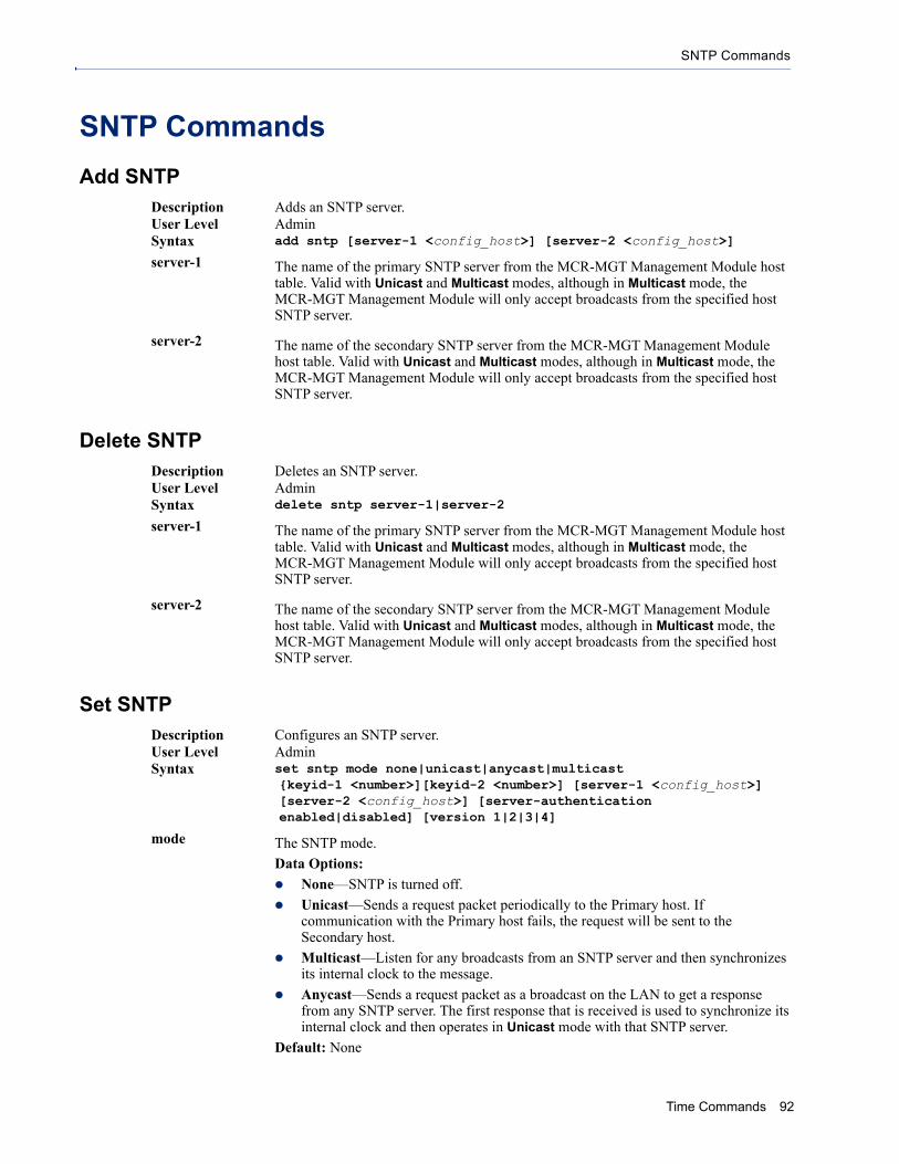
SNTP Commands
SNTP Commands
Add SNTP
Delete SNTP
Set SNTP
Description Adds an SNTP server.User Level AdminSyntax add sntp [server-1 <config_host>] [server-2 <config_host>]
server-1 The name of the primary SNTP server from the MCR-MGT Management Module host table. Valid with Unicast and Multicast modes, although in Multicast mode, the MCR-MGT Management Module will only accept broadcasts from the specified host SNTP server.
server-2 The name of the secondary SNTP server from the MCR-MGT Management Module host table. Valid with Unicast and Multicast modes, although in Multicast mode, the MCR-MGT Management Module will only accept broadcasts from the specified host SNTP server.
Description Deletes an SNTP server.User Level AdminSyntax delete sntp server-1|server-2
server-1 The name of the primary SNTP server from the MCR-MGT Management Module host table. Valid with Unicast and Multicast modes, although in Multicast mode, the MCR-MGT Management Module will only accept broadcasts from the specified host SNTP server.
server-2 The name of the secondary SNTP server from the MCR-MGT Management Module host table. Valid with Unicast and Multicast modes, although in Multicast mode, the MCR-MGT Management Module will only accept broadcasts from the specified host SNTP server.
Description Configures an SNTP server.User Level AdminSyntax set sntp mode none|unicast|anycast|multicast
{keyid-1 <number>][keyid-2 <number>] [server-1 <config_host>] [server-2 <config_host>] [server-authentication enabled|disabled] [version 1|2|3|4]
mode The SNTP mode.
Data Options:
None—SNTP is turned off.
Unicast—Sends a request packet periodically to the Primary host. If communication with the Primary host fails, the request will be sent to the Secondary host.
Multicast—Listen for any broadcasts from an SNTP server and then synchronizes its internal clock to the message.
Anycast—Sends a request packet as a broadcast on the LAN to get a response from any SNTP server. The first response that is received is used to synchronize its internal clock and then operates in Unicast mode with that SNTP server.
Default: None
Time Commands 92

SNTP Commands
Show SNTP
Show SNTP-Info
server-1 The name of the primary SNTP server from the MCR-MGT Management Module host table. Valid with Unicast and Multicast modes, although in Multicast mode, the MCR-MGT Management Module will only accept broadcasts from the specified host SNTP server.
server-2 The name of the secondary SNTP server from the MCR-MGT Management Module host table. Valid with Unicast and Multicast modes, although in Multicast mode, the MCR-MGT Management Module will only accept broadcasts from the specified host SNTP server.
Key ID Specify the key id associated with this host. This key must exist in the sntp (symmetric key) file that was downloaded to the MCR-MGT management card.
Valid Key ID’s: 1-65534
Note: the structure for the sntp (symmetric key ) file can be found in the MCR-MGT User Guide - Appendix F (Symmetric Key File)
version Version of SNTP.
Range: 1-4
Default: 4
Description Shows the SNTP settings.User Level Admin, OperatorSyntax show sntp
Description Shows current SNTP information.User Level Admin, OperatorSyntax show sntp-info
Time Commands 93

Time/Date Setting Commands
Time/Date Setting Commands
Set Date
Set Summertime
Set Summertime Fixed
Set Summertime Recurring
Description Sets the MCR-MGT Management Module’s system clock.User Level AdminSyntax set date <dd/mm/yyyy>
Description Sets the summertime clock.User Level AdminSyntax set summertime [mode none|fixed|recurring] [name <text>]
[offset <hh:mm>]
mode You can configure the summer time to take effect:
None—No summer time change.
Fixed—The summer time change goes into effect at the specified time every year. For example, April 15 at 1:00 pm.
Recurring—The summer time changes goes into effect every year at same relative time. For example, on the third week in April on a Tuesday at 1:00 pm.
Default: None
<name> The name of the configured summer time zone; this will be displayed during the summer time setting. If this parameter is not set, then the summertime feature will not work.
Field Format: Maximum 4 characters and minimum 3 characters (do not use angled brackets < >)
offset The offset from UTC for your local time zone.
Field Format: Hours hh (valid -12 to +14) and minutes mm (valid 0 to 59 minutes)
Description Sets the summertime clock to start on the same date each year, for example, April 15 at 1:00 pm.
User Level AdminSyntax set summertime fixed
[start-date january|february |... <0-31>] [start-time <hh:mm>] [end-date january|february|... <0-31>] [end-time <hh:mm>]
start-date The date to change to summer time and end standard time.
start-time <hh:mm> The time to change to summertime. Valid values are 00:00 to 23:59.
end-date The date to end summer time and start standard time.
end-time <hh:mm> The time to change to standard time.
Range: 00:00-23:59
Description Sets the summertime clock to start at the same relative time each year; for example, on the third week in April on a Tuesday at 1:00 pm.
Time Commands 94

Time/Date Setting Commands
Show Date
Show Summertime
User Level AdminSyntax set summertime recurring [start-day monday|tuesday|...]
[start-month january|february|...] [start-time <hh:mm>] [start-week 1|2|3|4|5|last] [end-day monday|tuesday|...] [end-month january|february|...] [end-time <hh:mm>] [end-week 1|2|3|4|5|last]
start-day The day to change to summer time from standard time.
start-month The month to change to summer time from standard time.
start-time The time to change to summer time from standard time; uses the format hh:mm for a 24-hour clock (00:00-23:59).
start-week The week to change to summer time from standard time.
end-day The day to end summer time and start standard time.
end-month The month to end summer time and start standard time.
end-time The time to end summer time and start standard time; uses the format hh:mm for a 24-hour clock (00:00-23:59).
end-week The week to end summer time and start standard time.
Description Shows the date, according to the MCR-MGT Management Module system clock.User Level Admin, OperatorSyntax show date
Description Shows the summertime settings.User Level Admin, OperatorSyntax show summertime
Time Commands 95

Statistics Commands 96
Statistics Commands Chapter 88Configuration Statistics
Show Interface
Run-Time Statistics
Delete Arp
Show Arp
Uptime
Description Shows IP statistics for Ethernet port.User Level Admin, OperatorSyntax show interface
Description Delete entries from the MCR-MGT Management Module's ARP cache. Takes effect immediately; not related to configuration.
User Level AdminSyntax delete arp
Description Shows the current contents of the ARP cache.User Level Admin, OperatorSyntax show arp
Description Displays the elapsed time (in days, hours, minutes, and seconds) since the last reboot/power cycle.
User Level Admin, OperatorSyntax uptime