Embed Size (px)
Citation preview
Replacement Parts List No. 57102900Revision W 10/2017
McQuay
SeasonpakScrew Compressor
Air-Cooled ChillerALS
125-204Vintage A
60 Hz.
Last Manufactured: 2000
To find your Daikin Applied parts distributor, call 1-800-377-2787 or visit www.DaikinApplied.com
Air Cooled Screw Chiller; ALS 125- 204, 60 Hz / Vintage A Rev. W 10/17 RPL 571029 / Page 2
Contents
Parts List Revision History..................................................................................................... 3Nomenclature Production Unit Model Number ........................................................................................ 4 Stock Unit Model Number ................................................................................................ 4 Serial Number .................................................................................................................. 4 Complete Model Number ............................................................................................ 5 - 6Compressors Compressor Arrangement, Sizes & Notes ....................................................................... 7 Compressors- Liquid Injected ..................................................................................... 8-10 Compressors- Oil Injected......................................................................................... 11-13Power Panel Components Diagrams ................................................................................................................... 14-15 ALS 125A .................................................................................................................. 16-17 ALS 140A ..................................................................................................................18-19 ALS 155A .................................................................................................................. 20-21 ALS 170A ..................................................................................................................22-23 ALS 175A .................................................................................................................. 24-25 ALS 185A .................................................................................................................. 26-27 ALS 195A ..................................................................................................................28-29 ALS 204A ..................................................................................................................30-31Control Panel Components ............................................................................................ 32-39Condenser Fan Section ALS 125A, 140A ........................................................................................................ 40-41 ALS 155A, 170A ........................................................................................................ 42-43 ALS 175A, 185A, 195A ............................................................................................. 44-45 ALS 204A .................................................................................................................. 44-45Cabinet ...........................................................................................................................48-51Piping Components Basic Information ........................................................................................................... 52 ALS 125A ....................................................................................................................... 53 ALS 140A ....................................................................................................................... 54 ALS 155A ....................................................................................................................... 55 ALS 170A ....................................................................................................................... 56 ALS 175A ....................................................................................................................... 57 ALS 185A ....................................................................................................................... 58 ALS 195A ....................................................................................................................... 59 ALS 204A ....................................................................................................................... 60Evaporator ...................................................................................................................... 61-64Condenser Coils .................................................................................................................. 65Wind Baffles and Hail Guards ............................................................................................. 66
Air Cooled Screw Chiller; ALS 125- 204, 60 Hz / Vintage A Rev. W 10/17 RPL 571029 / Page 3
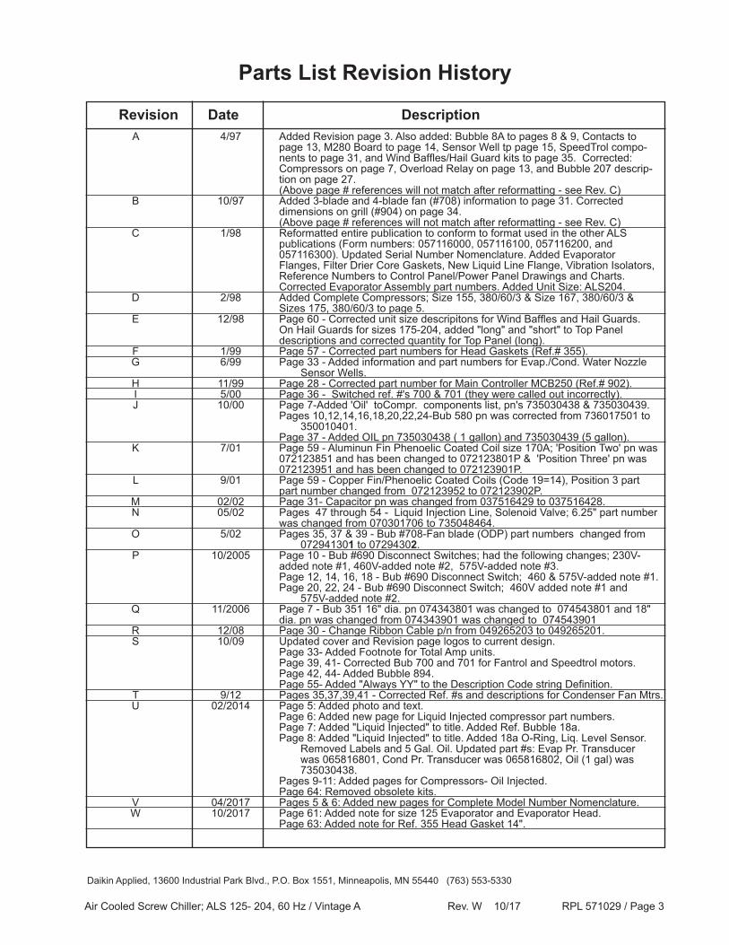
A 4/97 Added Revision page 3. Also added: Bubble 8A to pages 8 & 9, Contacts to page 13, M280 Board to page 14, Sensor Well tp page 15, SpeedTrol compo- nents to page 31, and Wind Baffles/Hail Guard kits to page 35. Corrected: Compressors on page 7, Overload Relay on page 13, and Bubble 207 descrip- tion on page 27. (Above page # references will not match after reformatting - see Rev. C) B 10/97 Added 3-blade and 4-blade fan (#708) information to page 31. Corrected dimensions on grill (#904) on page 34. (Above page # references will not match after reformatting - see Rev. C) C 1/98 Reformatted entire publication to conform to format used in the other ALS publications (Form numbers: 057116000, 057116100, 057116200, and 057116300). Updated Serial Number Nomenclature. Added Evaporator Flanges, Filter Drier Core Gaskets, New Liquid Line Flange, Vibration Isolators, Reference Numbers to Control Panel/Power Panel Drawings and Charts. Corrected Evaporator Assembly part numbers. Added Unit Size: ALS204. D 2/98 Added Complete Compressors; Size 155, 380/60/3 & Size 167, 380/60/3 & Sizes 175, 380/60/3 to page 5. E 12/98 Page 60 - Corrected unit size descripitons for Wind Baffles and Hail Guards. On Hail Guards for sizes 175-204, added "long" and "short" to Top Panel descriptions and corrected quantity for Top Panel (long). F 1/99 Page 57 - Corrected part numbers for Head Gaskets (Ref.# 355). G 6/99 Page 33 - Added information and part numbers for Evap./Cond. Water Nozzle Sensor Wells. H 11/99 Page 28 - Corrected part number for Main Controller MCB250 (Ref.# 902). I 5/00 Page 36 - Switched ref. #'s 700 & 701 (they were called out incorrectly). J 10/00 Page 7-Added 'Oil' toCompr. components list, pn's 735030438 & 735030439. Pages 10,12,14,16,18,20,22,24-Bub 580 pn was corrected from 736017501 to 350010401. Page 37 - Added OIL pn 735030438 ( 1 gallon) and 735030439 (5 gallon). K 7/01 Page 59 - Aluminun Fin Phenoelic Coated Coil size 170A; 'Position Two' pn was 072123851 and has been changed to 072123801P & 'Position Three' pn was 072123951 and has been changed to 072123901P. L 9/01 Page 59 - Copper Fin/Phenoelic Coated Coils (Code 19=14), Position 3 part part number changed from 072123952 to 072123902P. M 02/02 Page 31- Capacitor pn was changed from 037516429 to 037516428. N 05/02 Pages 47 through 54 - Liquid Injection Line, Solenoid Valve; 6.25" part number was changed from 070301706 to 735048464. O 5/02 Pages 35, 37 & 39 - Bub #708-Fan blade (ODP) part numbers changed from 072941301 to 07294302. P 10/2005 Page 10 - Bub #690 Disconnect Switches; had the following changes; 230V- added note #1, 460V-added note #2, 575V-added note #3. Page 12, 14, 16, 18 - Bub #690 Disconnect Switch; 460 & 575V-added note #1. Page 20, 22, 24 - Bub #690 Disconnect Switch; 460V added note #1 and 575V-added note #2. Q 11/2006 Page 7 - Bub 351 16" dia. pn 074343801 was changed to 074543801 and 18" dia. pn was changed from 074343901 was changed to 074543901 R 12/08 Page 30 - Change Ribbon Cable p/n from 049265203 to 049265201. S 10/09 Updated cover and Revision page logos to current design. Page 33- Added Footnote for Total Amp units. Page 39, 41- Corrected Bub 700 and 701 for Fantrol and Speedtrol motors. Page 42, 44- Added Bubble 894. Page 55- Added "Always YY" to the Description Code string Definition. T 9/12 Pages 35,37,39,41 - Corrected Ref. #s and descriptions for Condenser Fan Mtrs. U 02/2014 Page 5: Added photo and text. Page 6: Added new page for Liquid Injected compressor part numbers. Page 7: Added "Liquid Injected" to title. Added Ref. Bubble 18a. Page 8: Added "Liquid Injected" to title. Added 18a O-Ring, Liq. Level Sensor. Removed Labels and 5 Gal. Oil. Updated part #s: Evap Pr. Transducer was 065816801, Cond Pr. Transducer was 065816802, Oil (1 gal) was 735030438. Pages 9-11: Added pages for Compressors- Oil Injected. Page 64: Removed obsolete kits. V 04/2017 Pages 5 & 6: Added new pages for Complete Model Number Nomenclature. W 10/2017 Page 61: Added note for size 125 Evaporator and Evaporator Head. Page 63: Added note for Ref. 355 Head Gasket 14".
Revision Date Description
Parts List Revision History
Daikin Applied, 13600 Industrial Park Blvd., P.O. Box 1551, Minneapolis, MN 55440 (763) 553-5330
Air Cooled Screw Chiller; ALS 125- 204, 60 Hz / Vintage A Rev. W 10/17 RPL 571029 / Page 4
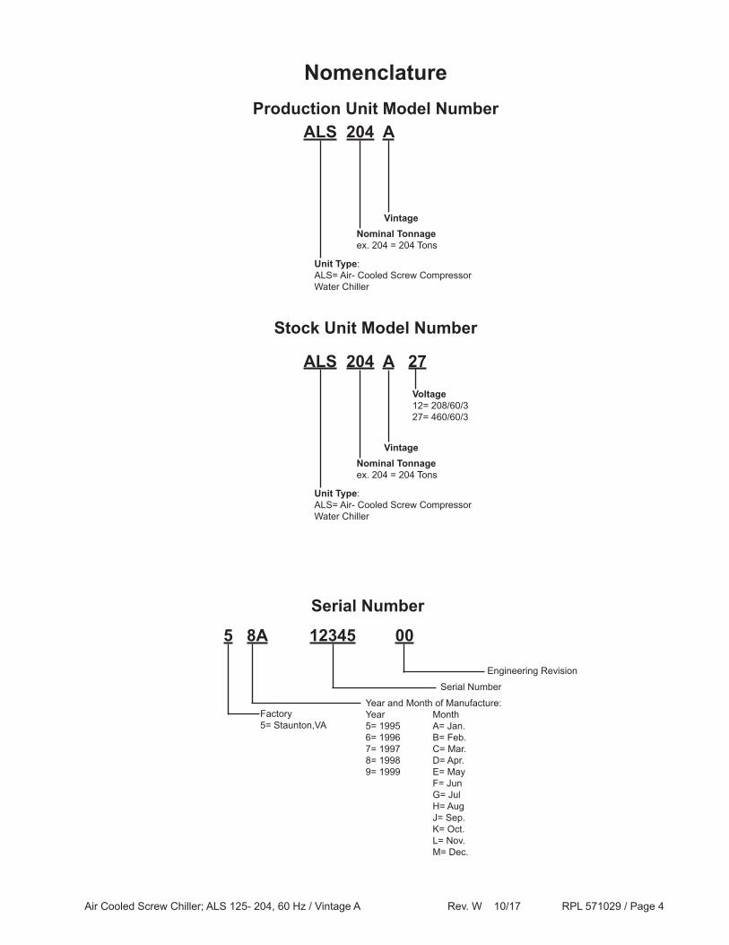
Nomenclature
ALS 204 AProduction Unit Model Number
Unit Type: ALS= Air- Cooled Screw Compressor Water Chiller
Nominal Tonnageex. 204 = 204 Tons
Vintage
Serial Number
5 8A 12345 00
Factory5= Staunton,VA
Serial Number
Year and Month of Manufacture: Year Month5= 1995 A= Jan.6= 1996 B= Feb.7= 1997 C= Mar.8= 1998 D= Apr.9= 1999 E= May F= Jun G= Jul H= Aug J= Sep. K= Oct. L= Nov. M= Dec.
Engineering Revision
ALS 204 A 27
Unit Type: ALS= Air- Cooled Screw Compressor Water Chiller
Nominal Tonnageex. 204 = 204 Tons
Vintage
Stock Unit Model Number
Voltage12= 208/60/327= 460/60/3
Air Cooled Screw Chiller; ALS 125- 204, 60 Hz / Vintage A Rev. W 10/17 RPL 571029 / Page 5
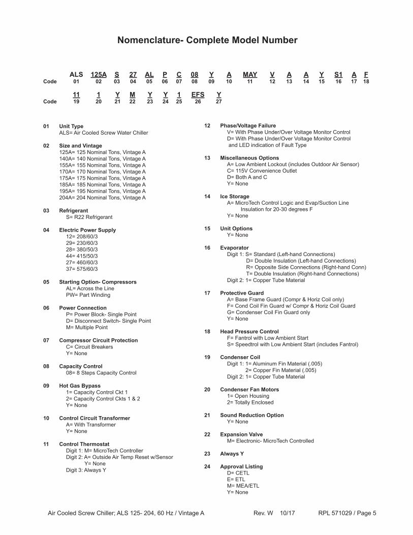
ALS 125A S 27 AL P C 08 Y A MAY V A A Y S1 A FCode 01 02 03 04 05 06 07 08 09 10 11 12 13 14 15 16 17 18
11 1 Y M Y Y 1 EFS Y Code 19 20 21 22 23 24 25 26 27
01 Unit Type ALS= Air Cooled Screw Water Chiller
02 Size and Vintage 125A= 125 Nominal Tons, Vintage A 140A= 140 Nominal Tons, Vintage A 155A= 155 Nominal Tons, Vintage A 170A= 170 Nominal Tons, Vintage A 175A= 175 Nominal Tons, Vintage A 185A= 185 Nominal Tons, Vintage A 195A= 195 Nominal Tons, Vintage A 204A= 204 Nominal Tons, Vintage A
03 Refrigerant S= R22 Refrigerant
04 Electric Power Supply 12= 208/60/3 29= 230/60/3 28= 380/50/3 44= 415/50/3 27= 460/60/3 37= 575/60/3
05 Starting Option- Compressors AL= Across the Line PW= Part Winding
06 Power Connection P= Power Block- Single Point D= Disconnect Switch- Single Point M= Multiple Point
07 Compressor Circuit Protection C= Circuit Breakers Y= None
08 Capacity Control 08= 8 Steps Capacity Control
09 Hot Gas Bypass 1= Capacity Control Ckt 1 2= Capacity Control Ckts 1 & 2 Y= None
10 Control Circuit Transformer A= With Transformer Y= None
11 Control Thermostat Digit 1: M= MicroTech Controller Digit 2: A= Outside Air Temp Reset w/Sensor Y= None Digit 3: Always Y
12 Phase/Voltage Failure V= With Phase Under/Over Voltage Monitor Control D= With Phase Under/Over Voltage Monitor Control and LED indication of Fault Type
13 Miscellaneous Options A= Low Ambient Lockout (includes Outdoor Air Sensor) C= 115V Convenience Outlet D= Both A and C Y= None
14 Ice Storage A= MicroTech Control Logic and Evap/Suction Line Insulation for 20-30 degrees F Y= None
15 Unit Options Y= None 16 Evaporator Digit 1: S= Standard (Left-hand Connections) D= Double Insulation (Left-hand Connections) R= Opposite Side Connections (Right-hand Conn) T= Double Insulation (Right-hand Connections) Digit 2: 1= Copper Tube Material
17 Protective Guard A= Base Frame Guard (Compr & Horiz Coil only) F= Cond Coil Fin Guard w/ Compr & Horiz Coil Guard G= Condenser Coil Fin Guard only Y= None
18 Head Pressure Control F= Fantrol with Low Ambient Start S= Speedtrol with Low Ambient Start (includes Fantrol)
19 Condenser Coil Digit 1: 1= Aluminum Fin Material (.005) 2= Copper Fin Material (.005) Digit 2: 1= Copper Tube Material
20 Condenser Fan Motors 1= Open Housing 2= Totally Enclosed
21 Sound Reduction Option Y= None
22 Expansion Valve M= Electronic- MicroTech Controlled
23 Always Y
24 Approval Listing D= CETL E= ETL M= MEA/ETL Y= None
Nomenclature- Complete Model Number
Air Cooled Screw Chiller; ALS 125- 204, 60 Hz / Vintage A Rev. W 10/17 RPL 571029 / Page 6
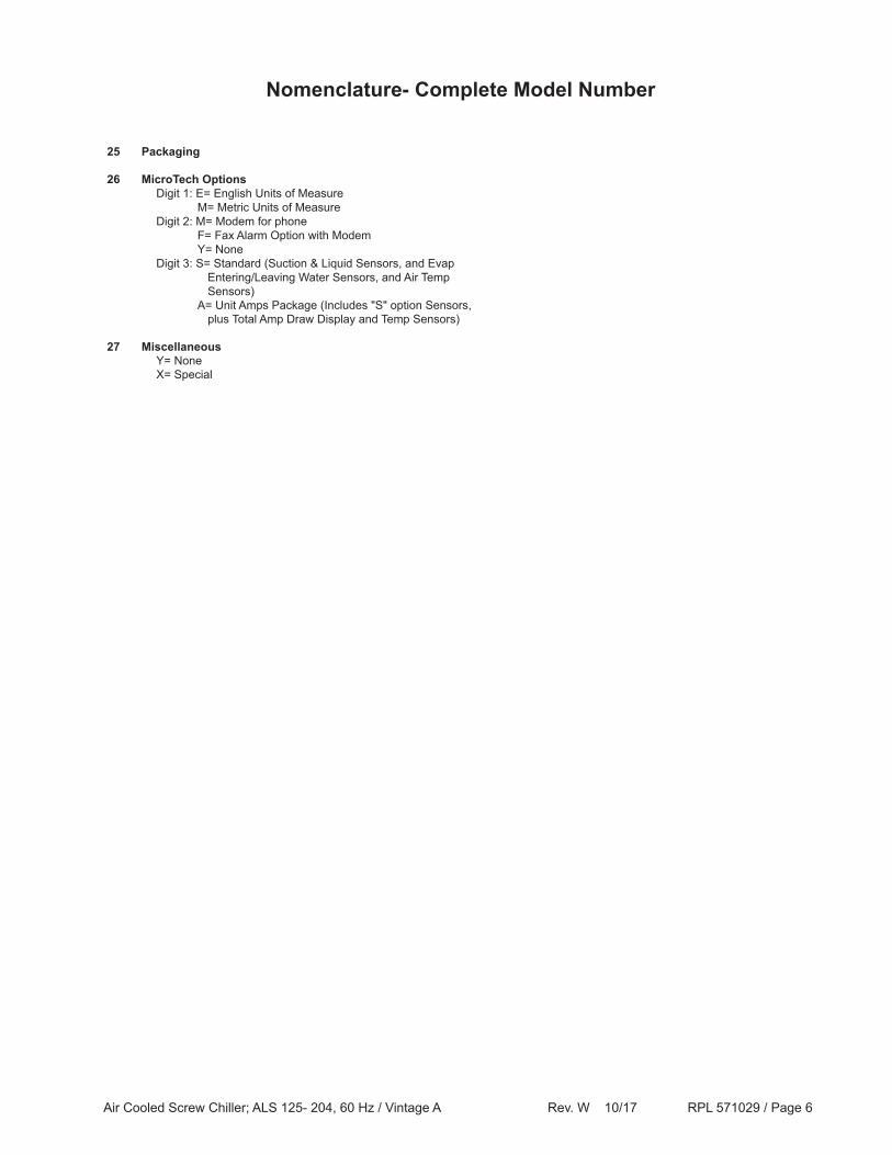
25 Packaging
26 MicroTech Options Digit 1: E= English Units of Measure M= Metric Units of Measure Digit 2: M= Modem for phone F= Fax Alarm Option with Modem Y= None Digit 3: S= Standard (Suction & Liquid Sensors, and Evap Entering/Leaving Water Sensors, and Air Temp Sensors) A= Unit Amps Package (Includes "S" option Sensors, plus Total Amp Draw Display and Temp Sensors)
27 Miscellaneous Y= None X= Special
Nomenclature- Complete Model Number
Air Cooled Screw Chiller; ALS 125- 204, 60 Hz / Vintage A Rev. W 10/17 RPL 571029 / Page 7
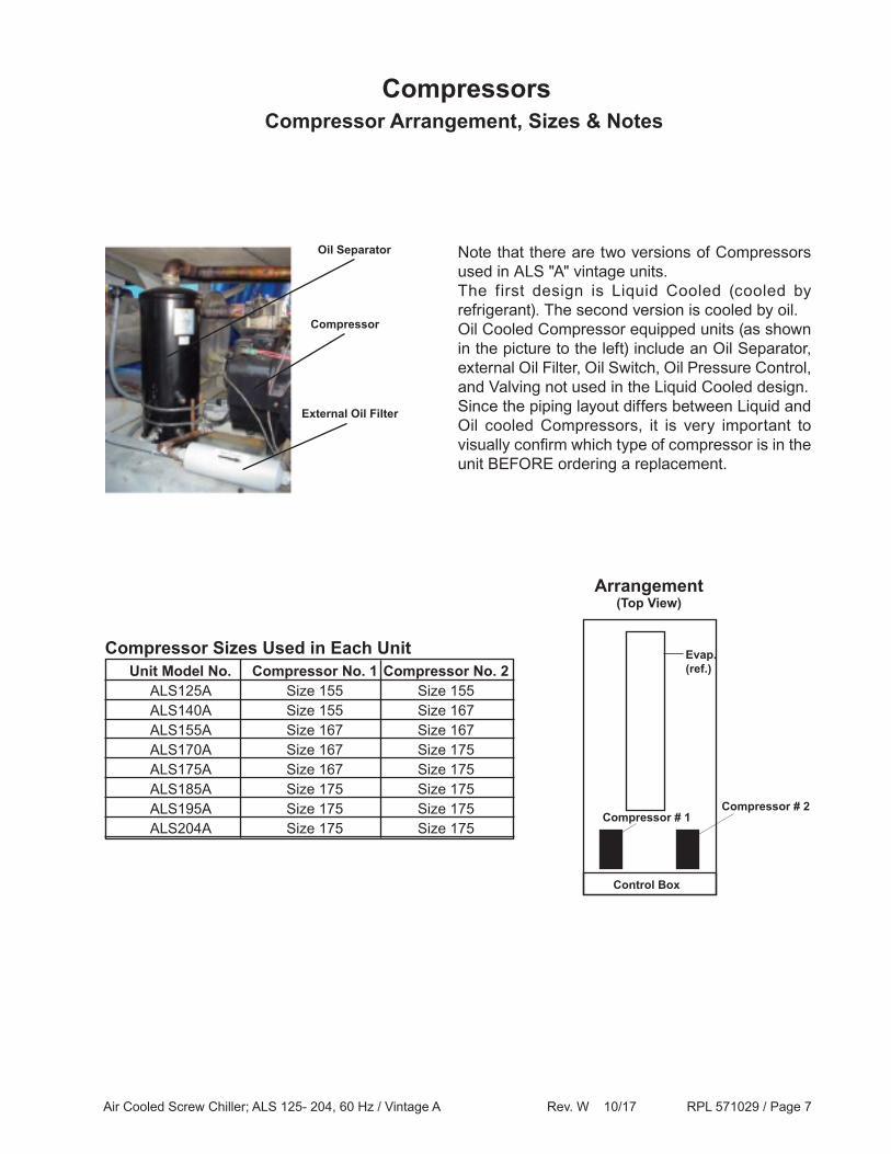
Unit Model No. Compressor No. 1 Compressor No. 2 ALS125A Size 155 Size 155 ALS140A Size 155 Size 167 ALS155A Size 167 Size 167 ALS170A Size 167 Size 175 ALS175A Size 167 Size 175 ALS185A Size 175 Size 175 ALS195A Size 175 Size 175 ALS204A Size 175 Size 175
CompressorsCompressor Arrangement, Sizes & Notes
Compressor Sizes Used in Each Unit
Arrangement(Top View)
Control Box
Compressor # 2Compressor # 1
Evap.(ref.)
Note that there are two versions of Compressors used in ALS "A" vintage units. The first design is Liquid Cooled (cooled by refrigerant). The second version is cooled by oil.Oil Cooled Compressor equipped units (as shown in the picture to the left) include an Oil Separator, external Oil Filter, Oil Switch, Oil Pressure Control, and Valving not used in the Liquid Cooled design.Since the piping layout differs between Liquid and Oil cooled Compressors, it is very important to visually confirm which type of compressor is in the unit BEFORE ordering a replacement.
Oil Separator
Compressor
External Oil Filter
Air Cooled Screw Chiller; ALS 125- 204, 60 Hz / Vintage A Rev. W 10/17 RPL 571029 / Page 8
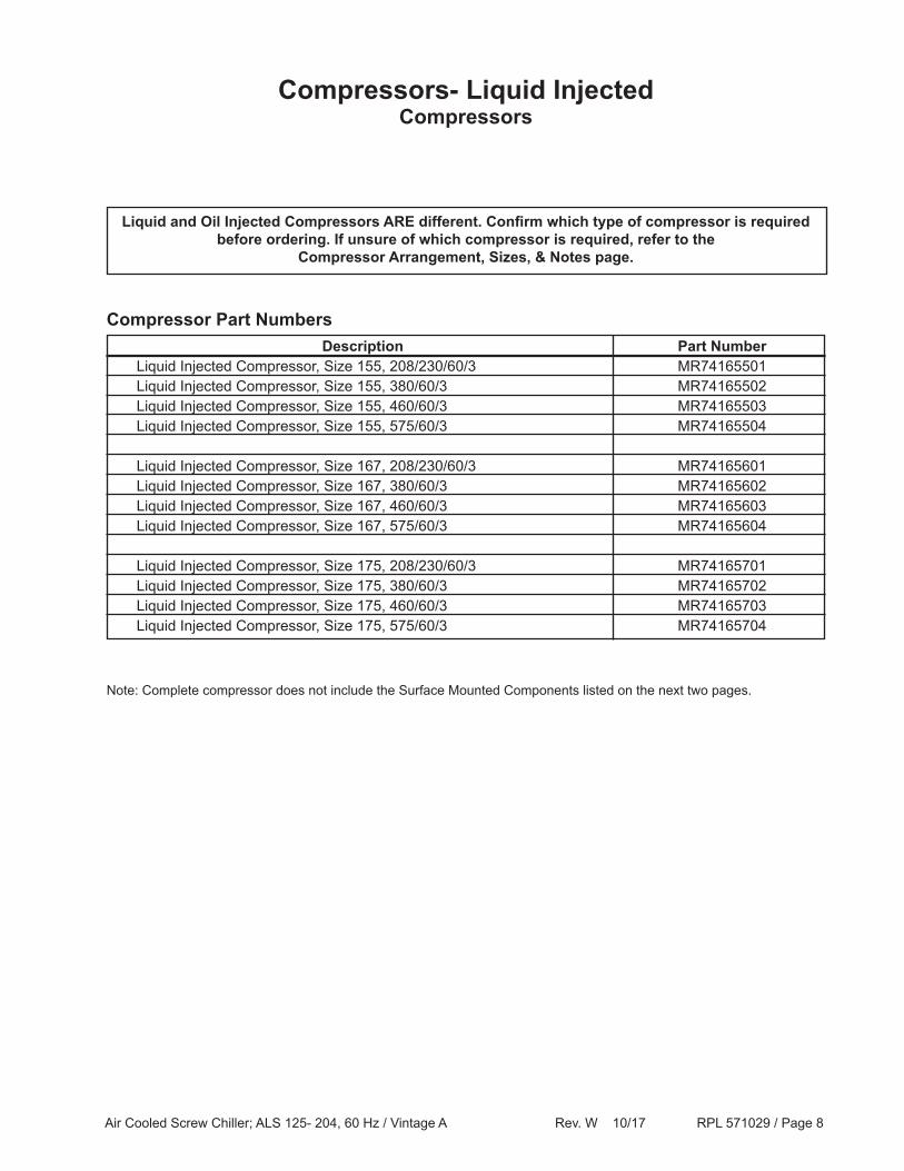
Compressors- Liquid InjectedCompressors
Description Part Number Liquid Injected Compressor, Size 155, 208/230/60/3 MR74165501 Liquid Injected Compressor, Size 155, 380/60/3 MR74165502 Liquid Injected Compressor, Size 155, 460/60/3 MR74165503 Liquid Injected Compressor, Size 155, 575/60/3 MR74165504
Liquid Injected Compressor, Size 167, 208/230/60/3 MR74165601 Liquid Injected Compressor, Size 167, 380/60/3 MR74165602 Liquid Injected Compressor, Size 167, 460/60/3 MR74165603 Liquid Injected Compressor, Size 167, 575/60/3 MR74165604
Liquid Injected Compressor, Size 175, 208/230/60/3 MR74165701 Liquid Injected Compressor, Size 175, 380/60/3 MR74165702 Liquid Injected Compressor, Size 175, 460/60/3 MR74165703 Liquid Injected Compressor, Size 175, 575/60/3 MR74165704
Compressor Part Numbers
Liquid and Oil Injected Compressors ARE different. Confirm which type of compressor is required before ordering. If unsure of which compressor is required, refer to the
Compressor Arrangement, Sizes, & Notes page.
Note: Complete compressor does not include the Surface Mounted Components listed on the next two pages.
Air Cooled Screw Chiller; ALS 125- 204, 60 Hz / Vintage A Rev. W 10/17 RPL 571029 / Page 9
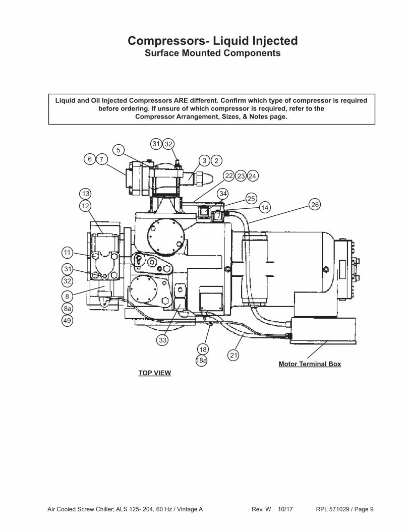
Compressors- Liquid InjectedSurface Mounted Components
2118
33
TOP VIEW
8
11
32
31
49
8a
13
12
53231
76 3 2
23 2422
3425
14 26
Motor Terminal Box
Liquid and Oil Injected Compressors ARE different. Confirm which type of compressor is required before ordering. If unsure of which compressor is required, refer to the
Compressor Arrangement, Sizes, & Notes page.
18a
Air Cooled Screw Chiller; ALS 125- 204, 60 Hz / Vintage A Rev. W 10/17 RPL 571029 / Page 10
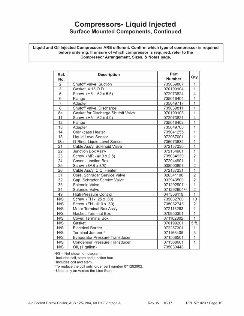
2 Shutoff Valve, Suction 735039807 1 3 Gasket, 4.15 O.D. 070199104 1 5 Screw (H5 - .62 x 5.5) 072973824 4 6 Flange 735016404 1 7 Adapter 735049717 1 8 Shutoff Valve, Discharge 735039811 1 8a Gasket for Discharge Shutoff Valve 070199108 1 11 Screw (H5 - .62 x 4.0) 072973821 4 12 Flange 735016402 1 13 Adapter 735049705 1 14 Crankcase Heater 735041255 1 18 Liquid Level Sensor 072967001 1 18a O-Ring, Liquid Level Sensor 735073634 1 21 Cable Ass'y, Solenoid Valve 072137330 1 22 Junction Box Ass'y 072134901 1 23 Screw (MR - #10 x 2.5) 735034939 2 24 Cover, Junction Box 072944901 1 25 Screw (8AB x 3/8) 038990807 2 26 Cable Ass'y, C.C. Heater 072137331 1 31 Core, Schrader Service Valve 026541100 2 32 Cap, Schrader Service Valve 032943500 2 33 Solenoid Valve 0712929011, 3 1 34 Solenoid Valve 0712929042, 3 2 49 High Pressure Control 047356119 1 N/S Screw (FH - .25 x .50) 735032780 10 N/S Screw (FH - #10 x .50) 735032743 2 N/S Motor Terminal Box Ass'y 072118263 1 N/S Gasket, Terminal Box 070950301 1 N/S Cover, Terminal Box 071162802 1 N/S Gasket 070199201 5 ft. N/S Electrical Barrier 072287301 1 N/S Terminal Jumper 4 071166405 3 N/S Evaporator Pressure Transducer 071568501 1 N/S Condenser Pressure Transducer 071568601 1 N/S Oil, (1 gallon) 735030448
Compressors- Liquid InjectedSurface Mounted Components, Continued
Ref.No.
Description
PartNumber
N/S = Not shown on diagram.1 Includes coil, stem and junction box.2 Includes coil and stem.3 To replace the coil only, order part number 071292902.4 Used only on Across-the-Line Start.
Qty.
Liquid and Oil Injected Compressors ARE different. Confirm which type of compressor is required before ordering. If unsure of which compressor is required, refer to the
Compressor Arrangement, Sizes, & Notes page.
Air Cooled Screw Chiller; ALS 125- 204, 60 Hz / Vintage A Rev. W 10/17 RPL 571029 / Page 11
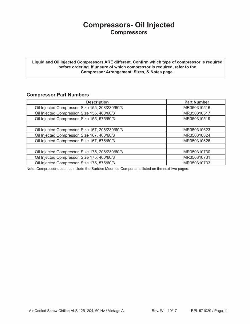
Compressors- Oil InjectedCompressors
Description Part Number Oil Injected Compressor, Size 155, 208/230/60/3 MR350310516 Oil Injected Compressor, Size 155, 460/60/3 MR350310517 Oil Injected Compressor, Size 155, 575/60/3 MR350310519
Oil Injected Compressor, Size 167, 208/230/60/3 MR350310623 Oil Injected Compressor, Size 167, 460/60/3 MR350310624 Oil Injected Compressor, Size 167, 575/60/3 MR350310626
Oil Injected Compressor, Size 175, 208/230/60/3 MR350310730 Oil Injected Compressor, Size 175, 460/60/3 MR350310731 Oil Injected Compressor, Size 175, 575/60/3 MR350310733Note: Compressor does not include the Surface Mounted Components listed on the next two pages.
Compressor Part Numbers
Liquid and Oil Injected Compressors ARE different. Confirm which type of compressor is required before ordering. If unsure of which compressor is required, refer to the
Compressor Arrangement, Sizes, & Notes page.
Air Cooled Screw Chiller; ALS 125- 204, 60 Hz / Vintage A Rev. W 10/17 RPL 571029 / Page 12
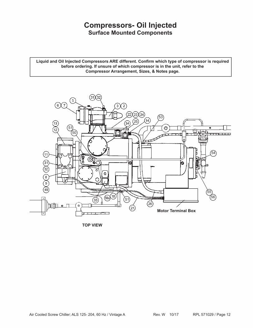
Compressors- Oil InjectedSurface Mounted Components
50
Liquid and Oil Injected Compressors ARE different. Confirm which type of compressor is required before ordering. If unsure of which compressor is in the unit, refer to the
Compressor Arrangement, Sizes, & Notes page.
TOP VIEW
54
53
51
Motor Terminal Box
51
5556
Air Cooled Screw Chiller; ALS 125- 204, 60 Hz / Vintage A Rev. W 10/17 RPL 571029 / Page 13
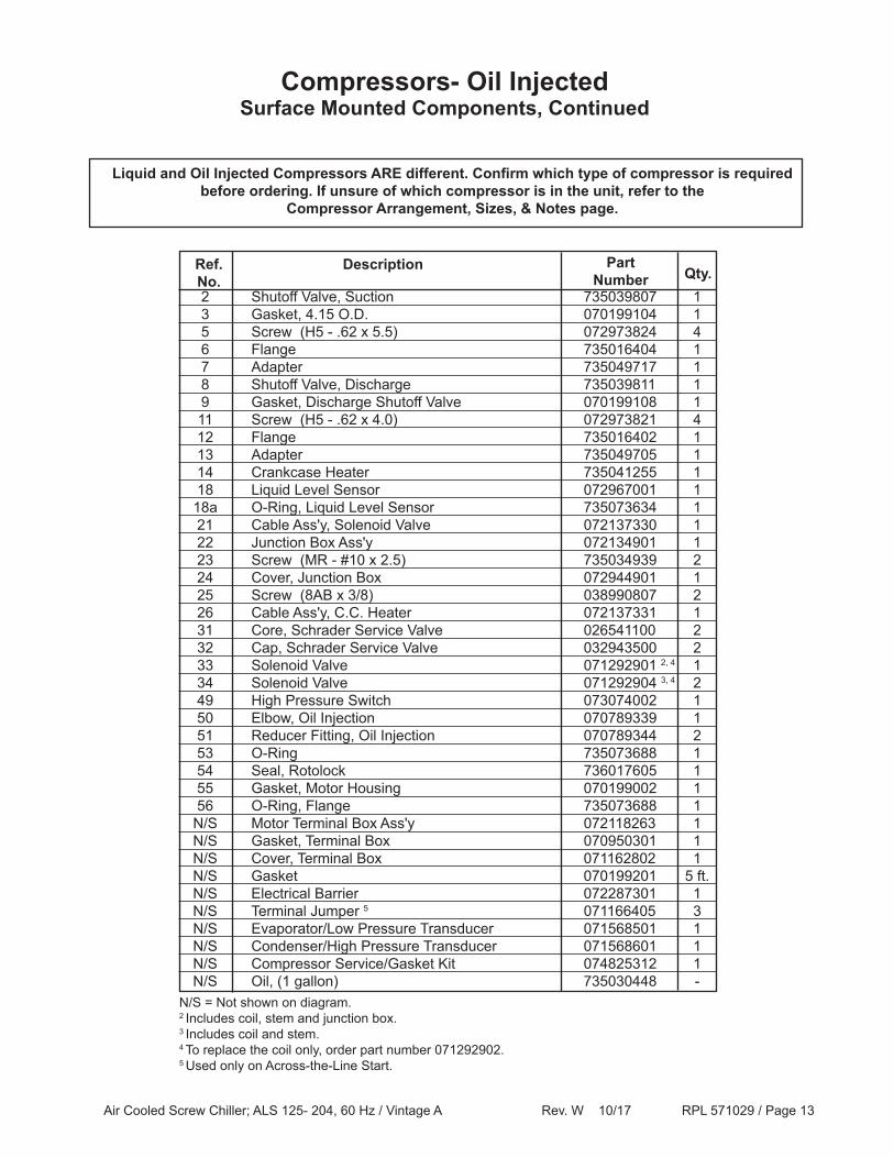
Compressors- Oil InjectedSurface Mounted Components, Continued
Liquid and Oil Injected Compressors ARE different. Confirm which type of compressor is required before ordering. If unsure of which compressor is in the unit, refer to the
Compressor Arrangement, Sizes, & Notes page.
2 Shutoff Valve, Suction 735039807 1 3 Gasket, 4.15 O.D. 070199104 1 5 Screw (H5 - .62 x 5.5) 072973824 4 6 Flange 735016404 1 7 Adapter 735049717 1 8 Shutoff Valve, Discharge 735039811 1 9 Gasket, Discharge Shutoff Valve 070199108 1 11 Screw (H5 - .62 x 4.0) 072973821 4 12 Flange 735016402 1 13 Adapter 735049705 1 14 Crankcase Heater 735041255 1 18 Liquid Level Sensor 072967001 1 18a O-Ring, Liquid Level Sensor 735073634 1 21 Cable Ass'y, Solenoid Valve 072137330 1 22 Junction Box Ass'y 072134901 1 23 Screw (MR - #10 x 2.5) 735034939 2 24 Cover, Junction Box 072944901 1 25 Screw (8AB x 3/8) 038990807 2 26 Cable Ass'y, C.C. Heater 072137331 1 31 Core, Schrader Service Valve 026541100 2 32 Cap, Schrader Service Valve 032943500 2 33 Solenoid Valve 071292901 2, 4 1 34 Solenoid Valve 071292904 3, 4 2 49 High Pressure Switch 073074002 1 50 Elbow, Oil Injection 070789339 1 51 Reducer Fitting, Oil Injection 070789344 2 53 O-Ring 735073688 1 54 Seal, Rotolock 736017605 1 55 Gasket, Motor Housing 070199002 1 56 O-Ring, Flange 735073688 1 N/S Motor Terminal Box Ass'y 072118263 1 N/S Gasket, Terminal Box 070950301 1 N/S Cover, Terminal Box 071162802 1 N/S Gasket 070199201 5 ft. N/S Electrical Barrier 072287301 1 N/S Terminal Jumper 5 071166405 3 N/S Evaporator/Low Pressure Transducer 071568501 1 N/S Condenser/High Pressure Transducer 071568601 1 N/S Compressor Service/Gasket Kit 074825312 1 N/S Oil, (1 gallon) 735030448 -
Ref.No.
Description
PartNumber Qty.
N/S = Not shown on diagram.2 Includes coil, stem and junction box.3 Includes coil and stem.4 To replace the coil only, order part number 071292902.5 Used only on Across-the-Line Start.
Air Cooled Screw Chiller; ALS 125- 204, 60 Hz / Vintage A Rev. W 10/17 RPL 571029 / Page 14
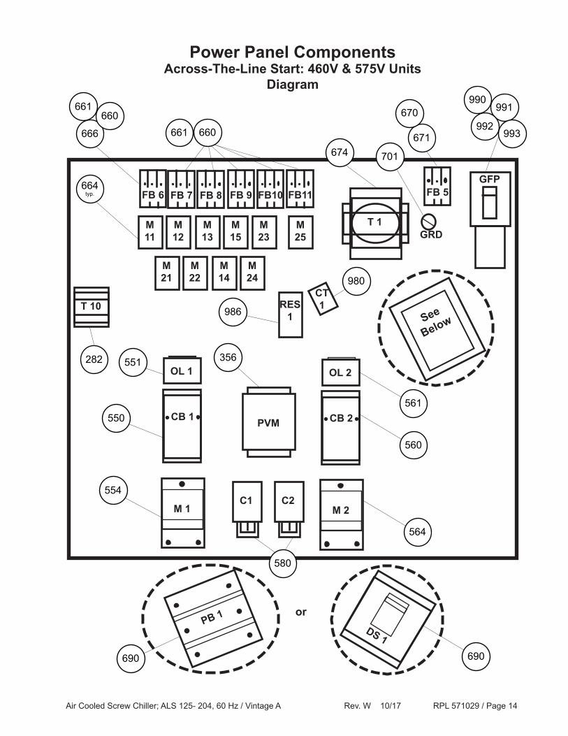
Across-The-Line Start: 460V & 575V UnitsDiagram
Power Panel Components
T 1
See
Below
FB 6
M11
PB 1DS 1
or
FB 8 FB 9 FB10 FB 5
M12
M13
M15
M23
T 10CT 1
PVM
FB 7 FB11
M25
M21
M22
M14
M24
CB 2
M 2
OL 2
CB 1
M 1
OL 1
666
660661
660661 671674 701
664typ.
282
991670992
993
990
GFP
980
RES 1986
551
550
554
356
561
560
564
C1 C2
580
690690
GRD
Air Cooled Screw Chiller; ALS 125- 204, 60 Hz / Vintage A Rev. W 10/17 RPL 571029 / Page 15
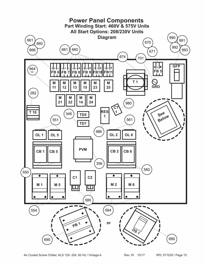
Part Winding Start: 460V & 575V UnitsAll Start Options: 208/230V Units
Diagram
Power Panel Components
T 1
See
Below
FB 6
M11
PB 1DS 1
or
FB 8 FB 9 FB10 FB 5
M12
M13
M15
M23
T 10CT 1
PVM
FB 7 FB11
M25
M21
M22
M14
M24
CB 1
M 1
OL 1
666
660661
660661 671674 701
664typ.
282
991670992
993
990
GFP
980
RES 1
986
356
C1 C2
580
690690
OL 5
CB 5
M 5
551
554
550
CB 2
M 2
OL 2 OL 6
CB 6
M 6
561
564
560
TD5
TD7
346
GRD
Air Cooled Screw Chiller; ALS 125- 204, 60 Hz / Vintage A Rev. W 10/17 RPL 571029 / Page 16
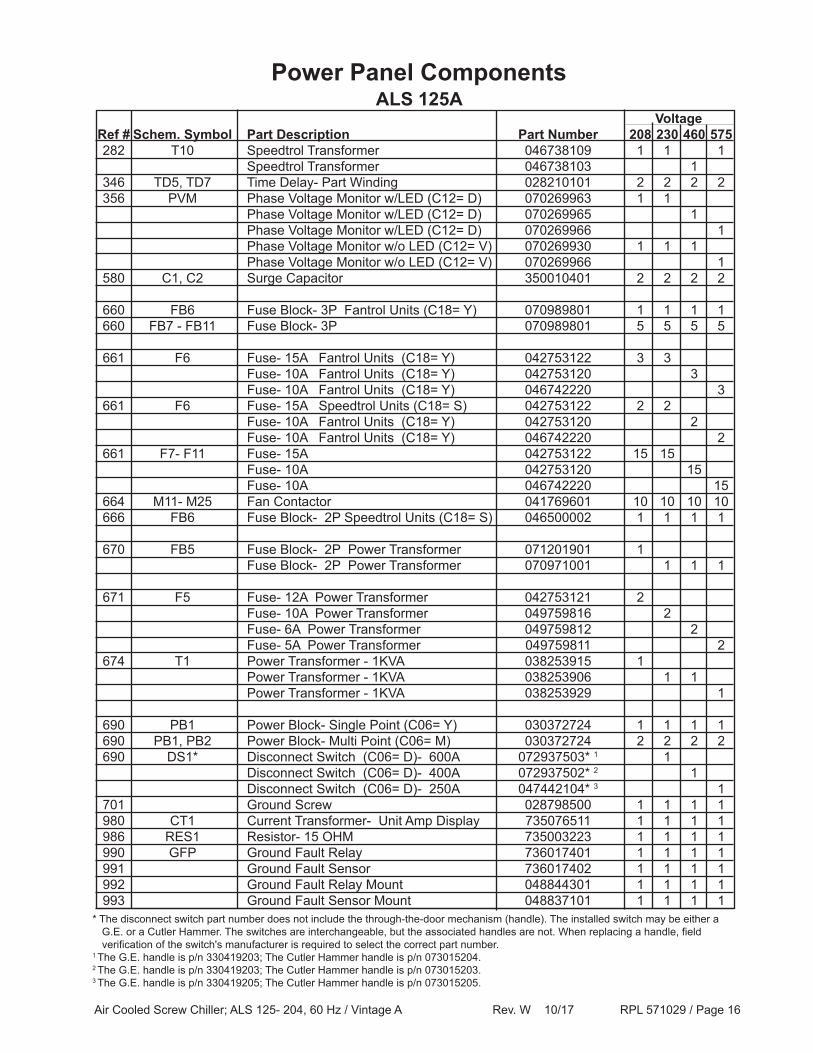
Voltage Ref # Schem. Symbol Part Description Part Number 208 230 460 575 282 T10 Speedtrol Transformer 046738109 1 1 1 Speedtrol Transformer 046738103 1 346 TD5, TD7 Time Delay- Part Winding 028210101 2 2 2 2 356 PVM Phase Voltage Monitor w/LED (C12= D) 070269963 1 1 Phase Voltage Monitor w/LED (C12= D) 070269965 1 Phase Voltage Monitor w/LED (C12= D) 070269966 1 Phase Voltage Monitor w/o LED (C12= V) 070269930 1 1 1 Phase Voltage Monitor w/o LED (C12= V) 070269966 1 580 C1, C2 Surge Capacitor 350010401 2 2 2 2
660 FB6 Fuse Block- 3P Fantrol Units (C18= Y) 070989801 1 1 1 1 660 FB7 - FB11 Fuse Block- 3P 070989801 5 5 5 5
661 F6 Fuse- 15A Fantrol Units (C18= Y) 042753122 3 3 Fuse- 10A Fantrol Units (C18= Y) 042753120 3 Fuse- 10A Fantrol Units (C18= Y) 046742220 3 661 F6 Fuse- 15A Speedtrol Units (C18= S) 042753122 2 2 Fuse- 10A Fantrol Units (C18= Y) 042753120 2 Fuse- 10A Fantrol Units (C18= Y) 046742220 2 661 F7- F11 Fuse- 15A 042753122 15 15 Fuse- 10A 042753120 15 Fuse- 10A 046742220 15 664 M11- M25 Fan Contactor 041769601 10 10 10 10 666 FB6 Fuse Block- 2P Speedtrol Units (C18= S) 046500002 1 1 1 1
670 FB5 Fuse Block- 2P Power Transformer 071201901 1 Fuse Block- 2P Power Transformer 070971001 1 1 1
671 F5 Fuse- 12A Power Transformer 042753121 2 Fuse- 10A Power Transformer 049759816 2 Fuse- 6A Power Transformer 049759812 2 Fuse- 5A Power Transformer 049759811 2 674 T1 Power Transformer - 1KVA 038253915 1 Power Transformer - 1KVA 038253906 1 1 Power Transformer - 1KVA 038253929 1
690 PB1 Power Block- Single Point (C06= Y) 030372724 1 1 1 1 690 PB1, PB2 Power Block- Multi Point (C06= M) 030372724 2 2 2 2 690 DS1* Disconnect Switch (C06= D)- 600A 072937503* 1 1 Disconnect Switch (C06= D)- 400A 072937502* 2 1 Disconnect Switch (C06= D)- 250A 047442104* 3 1 701 Ground Screw 028798500 1 1 1 1 980 CT1 Current Transformer- Unit Amp Display 735076511 1 1 1 1 986 RES1 Resistor- 15 OHM 735003223 1 1 1 1 990 GFP Ground Fault Relay 736017401 1 1 1 1 991 Ground Fault Sensor 736017402 1 1 1 1 992 Ground Fault Relay Mount 048844301 1 1 1 1 993 Ground Fault Sensor Mount 048837101 1 1 1 1
ALS 125APower Panel Components
* The disconnect switch part number does not include the through-the-door mechanism (handle). The installed switch may be either a G.E. or a Cutler Hammer. The switches are interchangeable, but the associated handles are not. When replacing a handle, field verification of the switch's manufacturer is required to select the correct part number.1 The G.E. handle is p/n 330419203; The Cutler Hammer handle is p/n 073015204.2 The G.E. handle is p/n 330419203; The Cutler Hammer handle is p/n 073015203.3 The G.E. handle is p/n 330419205; The Cutler Hammer handle is p/n 073015205.
Air Cooled Screw Chiller; ALS 125- 204, 60 Hz / Vintage A Rev. W 10/17 RPL 571029 / Page 17
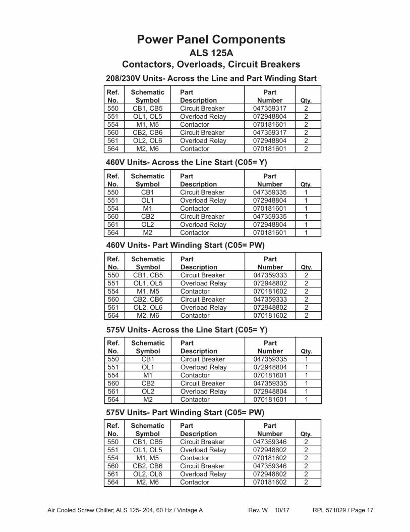
ALS 125AContactors, Overloads, Circuit Breakers
Power Panel Components
Ref. Schematic Part Part No. Symbol Description Number Qty. 550 CB1, CB5 Circuit Breaker 047359317 2 551 OL1, OL5 Overload Relay 072948804 2 554 M1, M5 Contactor 070181601 2 560 CB2, CB6 Circuit Breaker 047359317 2 561 OL2, OL6 Overload Relay 072948804 2 564 M2, M6 Contactor 070181601 2
208/230V Units- Across the Line and Part Winding Start
Ref. Schematic Part Part No. Symbol Description Number Qty. 550 CB1 Circuit Breaker 047359335 1 551 OL1 Overload Relay 072948804 1 554 M1 Contactor 070181601 1 560 CB2 Circuit Breaker 047359335 1 561 OL2 Overload Relay 072948804 1 564 M2 Contactor 070181601 1
460V Units- Across the Line Start (C05= Y)
Ref. Schematic Part Part No. Symbol Description Number Qty. 550 CB1, CB5 Circuit Breaker 047359333 2 551 OL1, OL5 Overload Relay 072948802 2 554 M1, M5 Contactor 070181602 2 560 CB2, CB6 Circuit Breaker 047359333 2 561 OL2, OL6 Overload Relay 072948802 2 564 M2, M6 Contactor 070181602 2
460V Units- Part Winding Start (C05= PW)
Ref. Schematic Part Part No. Symbol Description Number Qty. 550 CB1 Circuit Breaker 047359335 1 551 OL1 Overload Relay 072948804 1 554 M1 Contactor 070181601 1 560 CB2 Circuit Breaker 047359335 1 561 OL2 Overload Relay 072948804 1 564 M2 Contactor 070181601 1
575V Units- Across the Line Start (C05= Y)
Ref. Schematic Part Part No. Symbol Description Number Qty. 550 CB1, CB5 Circuit Breaker 047359346 2 551 OL1, OL5 Overload Relay 072948802 2 554 M1, M5 Contactor 070181602 2 560 CB2, CB6 Circuit Breaker 047359346 2 561 OL2, OL6 Overload Relay 072948802 2 564 M2, M6 Contactor 070181602 2
575V Units- Part Winding Start (C05= PW)
Air Cooled Screw Chiller; ALS 125- 204, 60 Hz / Vintage A Rev. W 10/17 RPL 571029 / Page 18
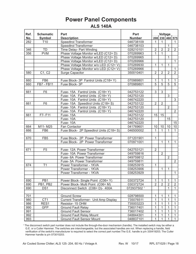
ALS 140APower Panel Components
Ref. Schematic Part Part Voltage No. Symbol Description Number 208 230 460 575 282 T10 Speedtrol Transformer 046738109 1 1 1 Speedtrol Transformer 046738103 1 346 TD Time Delay- Part Winding 028210101 2 2 2 2 356 PVM Phase Voltage Monitor w/LED (C12= D) 070269963 1 1 Phase Voltage Monitor w/LED (C12= D) 070269965 1 Phase Voltage Monitor w/LED (C12= D) 070269966 1 Phase Voltage Monitor w/o LED (C12= V) 070269930 1 1 1 Phase Voltage Monitor w/o LED (C12= V) 070269966 1 580 C1, C2 Surge Capacitor 350010401 2 2 2 2
660 FB6 Fuse Block- 3P Fantrol Units (C18= Y) 070989801 1 1 1 1 660 FB7 - FB11 Fuse Block- 3P 070989801 5 5 5 5
661 F6 Fuse- 15A Fantrol Units (C18= Y) 042753122 3 3 Fuse- 10A Fantrol Units (C18= Y) 042753120 3 Fuse- 10A Fantrol Units (C18= Y) 046742220 3 661 F6 Fuse- 15A Speedtrol Units (C18= S) 042753122 2 2 Fuse- 10A Fantrol Units (C18= Y) 042753120 2 Fuse- 10A Fantrol Units (C18= Y) 046742220 2 661 F7- F11 Fuse- 15A 042753122 15 15 Fuse- 10A 042753120 15 Fuse- 10A 046742220 15 664 M11- M25 Fan Contactor 041769601 10 10 10 10 666 FB6 Fuse Block- 2P Speedtrol Units (C18= S) 046500002 1 1 1 1
670 FB5 Fuse Block- 2P Power Transformer 071201901 1 Fuse Block- 2P Power Transformer 070971001 1 1 1
671 F5 Fuse- 12A Power Transformer 042753121 2 Fuse- 10A Power Transformer 049759816 2 Fuse- 6A Power Transformer 049759812 2 Fuse- 5A Power Transformer 049759811 2 674 T1 Power Transformer - 1KVA 038253915 1 Power Transformer - 1KVA 038253906 1 1 Power Transformer - 1KVA 038253929 1
690 PB1 Power Block- Single Point (C06= Y) 030372724 1 1 1 1 690 PB1, PB2 Power Block- Multi Point (C06= M) 030372724 2 2 2 2 690 DS1 Disconnect Switch (C06= D)- 400A 072937502 1 1 1
701 Ground Screw 028798500 1 1 1 1 980 CT1 Current Transformer- Unit Amp Display 735076511 1 1 1 1 986 RES1 Resistor- 15 OHM 735003223 1 1 1 1 990 GFP Ground Fault Relay 736017401 1 1 1 1 991 Ground Fault Sensor 736017402 1 1 1 1 992 Ground Fault Relay Mount 048844301 1 1 1 1 993 Ground Fault Sensor Mount 048837101 1 1 1 1
1 The disconnect switch part number does not include the through-the-door mechanism (handle). The installed switch may be either a G.E. or a Cutler Hammer. The switches are interchangeable, but the associated handles are not. When replacing a handle, field verification of the switch's manufacturer is required to select the correct part number.The G.E. handle is p/n 330419203; The Cutler Hammer handle is p/n 073015203.

Air Cooled Screw Chiller; ALS 125- 204, 60 Hz / Vintage A Rev. W 10/17 RPL 571029 / Page 19
ALS 140AContactors, Overloads, Circuit Breakers
Power Panel Components
Ref. Schematic Part Part No. Symbol Description Number Qty. 550 CB1, CB5 Circuit Breaker 047359317 2 551 OL1, OL5 Overload Relay 072948804 2 554 M1, M5 Contactor 070181601 2 560 CB2, CB6 Circuit Breaker 047359319 2 561 OL2, OL6 Overload Relay 072948804 2 564 M2, M6 Contactor 070181601 2
208/230V Units- Across the Line and Part Winding Start
Ref. Schematic Part Part No. Symbol Description Number Qty. 550 CB1 Circuit Breaker 047359335 1 551 OL1 Overload Relay 072948804 1 554 M1 Contactor 070181601 1 560 CB2 Circuit Breaker 047359335 1 561 OL2 Overload Relay 072948804 1 564 M2 Contactor 070181601 1
460V Units- Across the Line Start (C05= Y)
Ref. Schematic Part Part No. Symbol Description Number Qty. 550 CB1, CB5 Circuit Breaker 047359333 2 551 OL1, OL5 Overload Relay 072948802 2 554 M1, M5 Contactor 070181602 2 560 CB2, CB6 Circuit Breaker 047359333 2 561 OL2, OL6 Overload Relay 072948802 2 564 M2, M6 Contactor 070181602 2
460V Units- Part Winding Start (C05= PW)
Ref. Schematic Part Part No. Symbol Description Number Qty. 550 CB1 Circuit Breaker 047359335 1 551 OL1 Overload Relay 072948804 1 554 M1 Contactor 070181601 1 560 CB2 Circuit Breaker 047359335 1 561 OL2 Overload Relay 072948804 1 564 M2 Contactor 070181601 1
575V Units- Across the Line Start (C05= Y)
Ref. Schematic Part Part No. Symbol Description Number Qty. 550 CB1, CB5 Circuit Breaker 047359346 2 551 OL1, OL5 Overload Relay 072948802 2 554 M1, M5 Contactor 070181602 2 560 CB2, CB6 Circuit Breaker 047359348 2 561 OL2, OL6 Overload Relay 072948802 2 564 M2, M6 Contactor 070181602 2
575V Units- Part Winding Start (C05= PW)
Air Cooled Screw Chiller; ALS 125- 204, 60 Hz / Vintage A Rev. W 10/17 RPL 571029 / Page 20
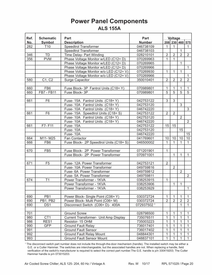
ALS 155APower Panel Components
Ref. Schematic Part Part Voltage No. Symbol Description Number 208 230 460 575 282 T10 Speedtrol Transformer 046738109 1 1 1 Speedtrol Transformer 046738103 1 346 TD Time Delay- Part Winding 028210101 2 2 2 2 356 PVM Phase Voltage Monitor w/LED (C12= D) 070269963 1 1 Phase Voltage Monitor w/LED (C12= D) 070269965 1 Phase Voltage Monitor w/LED (C12= D) 070269966 1 Phase Voltage Monitor w/o LED (C12= V) 070269930 1 1 1 Phase Voltage Monitor w/o LED (C12= V) 070269966 1 580 C1, C2 Surge Capacitor 350010401 2 2 2 2
660 FB6 Fuse Block- 3P Fantrol Units (C18= Y) 070989801 1 1 1 1 660 FB7 - FB11 Fuse Block- 3P 070989801 5 5 5 5
661 F6 Fuse- 15A Fantrol Units (C18= Y) 042753122 3 3 Fuse- 10A Fantrol Units (C18= Y) 042753120 3 Fuse- 10A Fantrol Units (C18= Y) 046742220 3 661 F6 Fuse- 15A Speedtrol Units (C18= S) 042753122 2 2 Fuse- 10A Fantrol Units (C18= Y) 042753120 2 Fuse- 10A Fantrol Units (C18= Y) 046742220 2 661 F7- F11 Fuse- 15A 042753122 15 15 Fuse- 10A 042753120 15 Fuse- 10A 046742220 15 664 M11- M25 Fan Contactor 041769601 10 10 10 10 666 FB6 Fuse Block- 2P Speedtrol Units (C18= S) 046500002 1 1 1 1
670 FB5 Fuse Block- 2P Power Transformer 071201901 1 Fuse Block- 2P Power Transformer 070971001 1 1 1
671 F5 Fuse- 12A Power Transformer 042753121 2 Fuse- 10A Power Transformer 049759816 2 Fuse- 6A Power Transformer 049759812 2 Fuse- 5A Power Transformer 049759811 2 674 T1 Power Transformer - 1KVA 038253915 1 Power Transformer - 1KVA 038253906 1 1 Power Transformer - 1KVA 038253929 1
690 PB1 Power Block- Single Point (C06= Y) 030372724 1 1 1 1 690 PB1, PB2 Power Block- Multi Point (C06= M) 030372724 2 2 2 2 690 DS1 Disconnect Switch (C06= D)- 400A 072937502 1 1 1
701 Ground Screw 028798500 1 1 1 1 980 CT1 Current Transformer- Unit Amp Display 735076511 1 1 1 1 986 RES1 Resistor- 15 OHM 735003223 1 1 1 1 990 GFP Ground Fault Relay 736017401 1 1 1 1 991 Ground Fault Sensor 736017402 1 1 1 1 992 Ground Fault Relay Mount 048844301 1 1 1 1 993 Ground Fault Sensor Mount 048837101 1 1 1 11 The disconnect switch part number does not include the through-the-door mechanism (handle). The installed switch may be either a G.E. or a Cutler Hammer. The switches are interchangeable, but the associated handles are not. When replacing a handle, field verification of the switch's manufacturer is required to select the correct part number.The G.E. handle is p/n 330419203; The Cutler Hammer handle is p/n 073015203.
Air Cooled Screw Chiller; ALS 125- 204, 60 Hz / Vintage A Rev. W 10/17 RPL 571029 / Page 21
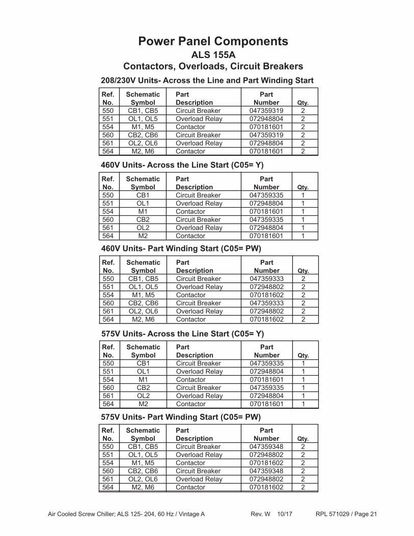
ALS 155AContactors, Overloads, Circuit Breakers
Power Panel Components
Ref. Schematic Part Part No. Symbol Description Number Qty. 550 CB1, CB5 Circuit Breaker 047359319 2 551 OL1, OL5 Overload Relay 072948804 2 554 M1, M5 Contactor 070181601 2 560 CB2, CB6 Circuit Breaker 047359319 2 561 OL2, OL6 Overload Relay 072948804 2 564 M2, M6 Contactor 070181601 2
208/230V Units- Across the Line and Part Winding Start
Ref. Schematic Part Part No. Symbol Description Number Qty. 550 CB1 Circuit Breaker 047359335 1 551 OL1 Overload Relay 072948804 1 554 M1 Contactor 070181601 1 560 CB2 Circuit Breaker 047359335 1 561 OL2 Overload Relay 072948804 1 564 M2 Contactor 070181601 1
460V Units- Across the Line Start (C05= Y)
Ref. Schematic Part Part No. Symbol Description Number Qty. 550 CB1, CB5 Circuit Breaker 047359333 2 551 OL1, OL5 Overload Relay 072948802 2 554 M1, M5 Contactor 070181602 2 560 CB2, CB6 Circuit Breaker 047359333 2 561 OL2, OL6 Overload Relay 072948802 2 564 M2, M6 Contactor 070181602 2
460V Units- Part Winding Start (C05= PW)
Ref. Schematic Part Part No. Symbol Description Number Qty. 550 CB1 Circuit Breaker 047359335 1 551 OL1 Overload Relay 072948804 1 554 M1 Contactor 070181601 1 560 CB2 Circuit Breaker 047359335 1 561 OL2 Overload Relay 072948804 1 564 M2 Contactor 070181601 1
575V Units- Across the Line Start (C05= Y)
Ref. Schematic Part Part No. Symbol Description Number Qty. 550 CB1, CB5 Circuit Breaker 047359348 2 551 OL1, OL5 Overload Relay 072948802 2 554 M1, M5 Contactor 070181602 2 560 CB2, CB6 Circuit Breaker 047359348 2 561 OL2, OL6 Overload Relay 072948802 2 564 M2, M6 Contactor 070181602 2
575V Units- Part Winding Start (C05= PW)
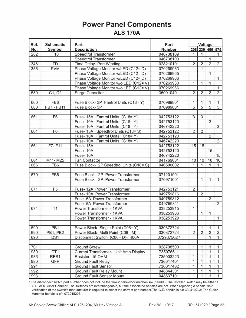
Air Cooled Screw Chiller; ALS 125- 204, 60 Hz / Vintage A Rev. W 10/17 RPL 571029 / Page 22
ALS 170APower Panel Components
Ref. Schematic Part Part Voltage No. Symbol Description Number 208 230 460 575 282 T10 Speedtrol Transformer 046738109 1 1 1 Speedtrol Transformer 046738103 1 346 TD Time Delay- Part Winding 028210101 2 2 2 2 356 PVM Phase Voltage Monitor w/LED (C12= D) 070269963 1 1 Phase Voltage Monitor w/LED (C12= D) 070269965 1 Phase Voltage Monitor w/LED (C12= D) 070269966 1 Phase Voltage Monitor w/o LED (C12= V) 070269930 1 1 1 Phase Voltage Monitor w/o LED (C12= V) 070269966 1 580 C1, C2 Surge Capacitor 350010401 2 2 2 2
660 FB6 Fuse Block- 3P Fantrol Units (C18= Y) 070989801 1 1 1 1 660 FB7 - FB11 Fuse Block- 3P 070989801 5 5 5 5
661 F6 Fuse- 15A Fantrol Units (C18= Y) 042753122 3 3 Fuse- 10A Fantrol Units (C18= Y) 042753120 3 Fuse- 10A Fantrol Units (C18= Y) 046742220 3 661 F6 Fuse- 15A Speedtrol Units (C18= S) 042753122 2 2 Fuse- 10A Fantrol Units (C18= Y) 042753120 2 Fuse- 10A Fantrol Units (C18= Y) 046742220 2 661 F7- F11 Fuse- 15A 042753122 15 15 Fuse- 10A 042753120 15 Fuse- 10A 046742220 15 664 M11- M25 Fan Contactor 041769601 10 10 10 10 666 FB6 Fuse Block- 2P Speedtrol Units (C18= S) 046500002 1 1 1 1
670 FB5 Fuse Block- 2P Power Transformer 071201901 1 Fuse Block- 2P Power Transformer 070971001 1 1 1
671 F5 Fuse- 12A Power Transformer 042753121 2 Fuse- 10A Power Transformer 049759816 2 Fuse- 6A Power Transformer 049759812 2 Fuse- 5A Power Transformer 049759811 2 674 T1 Power Transformer - 1KVA 038253915 1 Power Transformer - 1KVA 038253906 1 1 Power Transformer - 1KVA 038253929 1
690 PB1 Power Block- Single Point (C06= Y) 030372724 1 1 1 1 690 PB1, PB2 Power Block- Multi Point (C06= M) 030372724 2 2 2 2 690 DS1 Disconnect Switch (C06= D)- 400A 072937502 1 1 1
701 Ground Screw 028798500 1 1 1 1 980 CT1 Current Transformer- Unit Amp Display 735076511 1 1 1 1 986 RES1 Resistor- 15 OHM 735003223 1 1 1 1 990 GFP Ground Fault Relay 736017401 1 1 1 1 991 Ground Fault Sensor 736017402 1 1 1 1 992 Ground Fault Relay Mount 048844301 1 1 1 1 993 Ground Fault Sensor Mount 048837101 1 1 1 11 The disconnect switch part number does not include the through-the-door mechanism (handle). The installed switch may be either a G.E. or a Cutler Hammer. The switches are interchangeable, but the associated handles are not. When replacing a handle, field verification of the switch's manufacturer is required to select the correct part number.The G.E. handle is p/n 330419203; The Cutler Hammer handle is p/n 073015203.

Air Cooled Screw Chiller; ALS 125- 204, 60 Hz / Vintage A Rev. W 10/17 RPL 571029 / Page 23
ALS 170AContactors, Overloads, Circuit Breakers
Power Panel Components
Ref. Schematic Part Part No. Symbol Description Number Qty. 550 CB1, CB5 Circuit Breaker 047359319 2 551 OL1, OL5 Overload Relay 072948804 2 554 M1, M5 Contactor 070181601 2 560 CB2, CB6 Circuit Breaker 047359318 2 561 OL2, OL6 Overload Relay 072948804 2 564 M2, M6 Contactor 070181601 2
208/230V Units- Across the Line and Part Winding Start
Ref. Schematic Part Part No. Symbol Description Number Qty. 550 CB1 Circuit Breaker 047359335 1 551 OL1 Overload Relay 072948804 1 554 M1 Contactor 070181601 1 560 CB2 Circuit Breaker 047359336 1 561 OL2 Overload Relay 072948804 1 564 M2 Contactor 070181601 1
460V Units- Across the Line Start (C05= Y)
Ref. Schematic Part Part No. Symbol Description Number Qty. 550 CB1, CB5 Circuit Breaker 047359333 2 551 OL1, OL5 Overload Relay 072948802 2 554 M1, M5 Contactor 070181602 2 560 CB2, CB6 Circuit Breaker 047359334 2 561 OL2, OL6 Overload Relay 072948803 2 564 M2, M6 Contactor 070181602 2
460V Units- Part Winding Start (C05= PW)
Ref. Schematic Part Part No. Symbol Description Number Qty. 550 CB1 Circuit Breaker 047359335 1 551 OL1 Overload Relay 072948804 1 554 M1 Contactor 070181601 1 560 CB2 Circuit Breaker 047359335 1 561 OL2 Overload Relay 072948804 1 564 M2 Contactor 070181601 1
575V Units- Across the Line Start (C05= Y)
Ref. Schematic Part Part No. Symbol Description Number Qty. 550 CB1, CB5 Circuit Breaker 047359348 2 551 OL1, OL5 Overload Relay 072948802 2 554 M1, M5 Contactor 070181602 2 560 CB2, CB6 Circuit Breaker 047359333 2 561 OL2, OL6 Overload Relay 072948802 2 564 M2, M6 Contactor 070181602 2
575V Units- Part Winding Start (C05= PW)
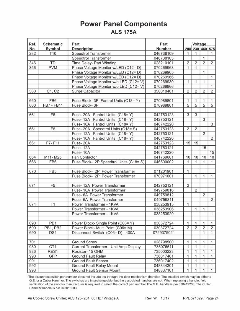
Air Cooled Screw Chiller; ALS 125- 204, 60 Hz / Vintage A Rev. W 10/17 RPL 571029 / Page 24
ALS 175APower Panel Components
Ref. Schematic Part Part Voltage No. Symbol Description Number 208 230 460 575 282 T10 Speedtrol Transformer 046738109 1 1 1 Speedtrol Transformer 046738103 1 346 TD Time Delay- Part Winding 028210101 2 2 2 2 356 PVM Phase Voltage Monitor w/LED (C12= D) 070269963 1 1 Phase Voltage Monitor w/LED (C12= D) 070269965 1 Phase Voltage Monitor w/LED (C12= D) 070269966 1 Phase Voltage Monitor w/o LED (C12= V) 070269930 1 1 1 Phase Voltage Monitor w/o LED (C12= V) 070269966 1 580 C1, C2 Surge Capacitor 350010401 2 2 2 2
660 FB6 Fuse Block- 3P Fantrol Units (C18= Y) 070989801 1 1 1 1 660 FB7 - FB11 Fuse Block- 3P 070989801 5 5 5 5
661 F6 Fuse- 20A Fantrol Units (C18= Y) 042753123 3 3 Fuse- 12A Fantrol Units (C18= Y) 042753121 3 Fuse- 10A Fantrol Units (C18= Y) 046742220 3 661 F6 Fuse- 20A Speedtrol Units (C18= S) 042753123 2 2 Fuse- 12A Fantrol Units (C18= Y) 042753121 2 Fuse- 10A Fantrol Units (C18= Y) 046742220 2 661 F7- F11 Fuse- 20A 042753123 15 15 Fuse- 12A 042753121 15 Fuse- 10A 046742220 15 664 M11- M25 Fan Contactor 041769601 10 10 10 10 666 FB6 Fuse Block- 2P Speedtrol Units (C18= S) 046500002 1 1 1 1
670 FB5 Fuse Block- 2P Power Transformer 071201901 1 Fuse Block- 2P Power Transformer 070971001 1 1 1
671 F5 Fuse- 12A Power Transformer 042753121 2 Fuse- 10A Power Transformer 049759816 2 Fuse- 6A Power Transformer 049759812 2 Fuse- 5A Power Transformer 049759811 2 674 T1 Power Transformer - 1KVA 038253915 1 Power Transformer - 1KVA 038253906 1 1 Power Transformer - 1KVA 038253929 1
690 PB1 Power Block- Single Point (C06= Y) 030372724 1 1 1 1 690 PB1, PB2 Power Block- Multi Point (C06= M) 030372724 2 2 2 2 690 DS1 Disconnect Switch (C06= D)- 400A 072937502 1 1 1
701 Ground Screw 028798500 1 1 1 1 980 CT1 Current Transformer- Unit Amp Display 735076511 1 1 1 1 986 RES1 Resistor- 15 OHM 735003223 1 1 1 1 990 GFP Ground Fault Relay 736017401 1 1 1 1 991 Ground Fault Sensor 736017402 1 1 1 1 992 Ground Fault Relay Mount 048844301 1 1 1 1 993 Ground Fault Sensor Mount 048837101 1 1 1 1
1 The disconnect switch part number does not include the through-the-door mechanism (handle). The installed switch may be either a G.E. or a Cutler Hammer. The switches are interchangeable, but the associated handles are not. When replacing a handle, field verification of the switch's manufacturer is required to select the correct part number.The G.E. handle is p/n 330419203; The Cutler Hammer handle is p/n 073015203.

Air Cooled Screw Chiller; ALS 125- 204, 60 Hz / Vintage A Rev. W 10/17 RPL 571029 / Page 25
ALS 175AContactors, Overloads, Circuit Breakers
Power Panel Components
Ref. Schematic Part Part No. Symbol Description Number Qty. 550 CB1, CB5 Circuit Breaker 047359319 2 551 OL1, OL5 Overload Relay 072948804 2 554 M1, M5 Contactor 070181601 2 560 CB2, CB6 Circuit Breaker 047359318 2 561 OL2, OL6 Overload Relay 072948804 2 564 M2, M6 Contactor 070181601 2
208/230V Units- Across the Line and Part Winding Start
Ref. Schematic Part Part No. Symbol Description Number Qty. 550 CB1 Circuit Breaker 047359335 1 551 OL1 Overload Relay 072948804 1 554 M1 Contactor 070181601 1 560 CB2 Circuit Breaker 047359336 1 561 OL2 Overload Relay 072948804 1 564 M2 Contactor 070181601 1
460V Units- Across the Line Start (C05= Y)
Ref. Schematic Part Part No. Symbol Description Number Qty. 550 CB1, CB5 Circuit Breaker 047359333 2 551 OL1, OL5 Overload Relay 072948802 2 554 M1, M5 Contactor 070181602 2 560 CB2, CB6 Circuit Breaker 047359334 2 561 OL2, OL6 Overload Relay 072948803 2 564 M2, M6 Contactor 070181602 2
460V Units- Part Winding Start (C05= PW)
Ref. Schematic Part Part No. Symbol Description Number Qty. 550 CB1 Circuit Breaker 047359335 1 551 OL1 Overload Relay 072948804 1 554 M1 Contactor 070181601 1 560 CB2 Circuit Breaker 047359335 1 561 OL2 Overload Relay 072948804 1 564 M2 Contactor 070181601 1
575V Units- Across the Line Start (C05= Y)
Ref. Schematic Part Part No. Symbol Description Number Qty. 550 CB1, CB5 Circuit Breaker 047359348 2 551 OL1, OL5 Overload Relay 072948802 2 554 M1, M5 Contactor 070181602 2 560 CB2, CB6 Circuit Breaker 047359333 2 561 OL2, OL6 Overload Relay 072948802 2 564 M2, M6 Contactor 070181602 2
575V Units- Part Winding Start (C05= PW)
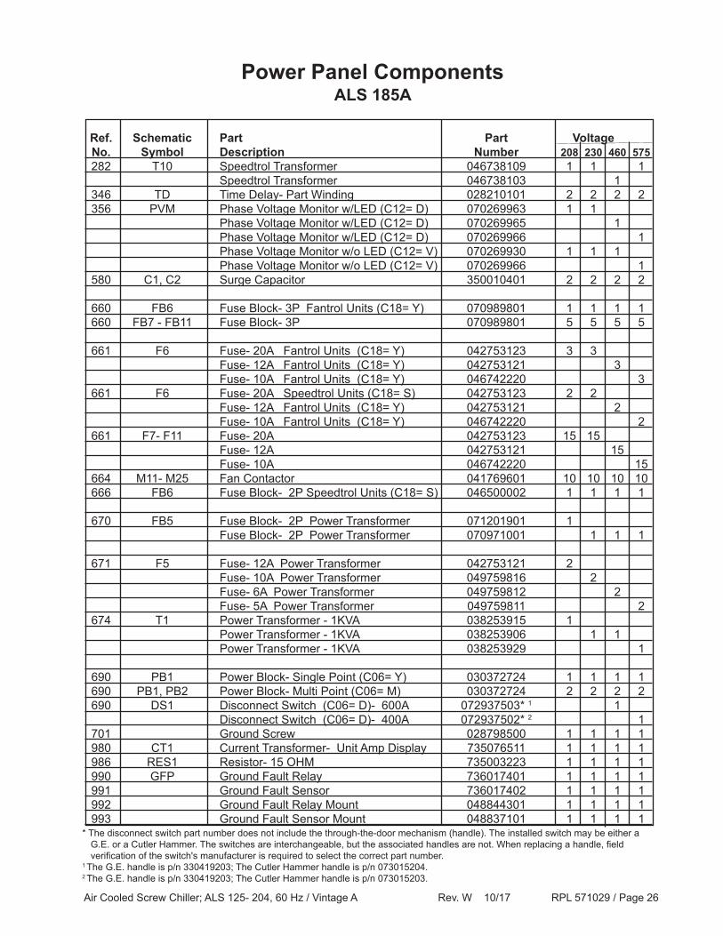
Air Cooled Screw Chiller; ALS 125- 204, 60 Hz / Vintage A Rev. W 10/17 RPL 571029 / Page 26
ALS 185APower Panel Components
Ref. Schematic Part Part Voltage No. Symbol Description Number 208 230 460 575 282 T10 Speedtrol Transformer 046738109 1 1 1 Speedtrol Transformer 046738103 1 346 TD Time Delay- Part Winding 028210101 2 2 2 2 356 PVM Phase Voltage Monitor w/LED (C12= D) 070269963 1 1 Phase Voltage Monitor w/LED (C12= D) 070269965 1 Phase Voltage Monitor w/LED (C12= D) 070269966 1 Phase Voltage Monitor w/o LED (C12= V) 070269930 1 1 1 Phase Voltage Monitor w/o LED (C12= V) 070269966 1 580 C1, C2 Surge Capacitor 350010401 2 2 2 2
660 FB6 Fuse Block- 3P Fantrol Units (C18= Y) 070989801 1 1 1 1 660 FB7 - FB11 Fuse Block- 3P 070989801 5 5 5 5
661 F6 Fuse- 20A Fantrol Units (C18= Y) 042753123 3 3 Fuse- 12A Fantrol Units (C18= Y) 042753121 3 Fuse- 10A Fantrol Units (C18= Y) 046742220 3 661 F6 Fuse- 20A Speedtrol Units (C18= S) 042753123 2 2 Fuse- 12A Fantrol Units (C18= Y) 042753121 2 Fuse- 10A Fantrol Units (C18= Y) 046742220 2 661 F7- F11 Fuse- 20A 042753123 15 15 Fuse- 12A 042753121 15 Fuse- 10A 046742220 15 664 M11- M25 Fan Contactor 041769601 10 10 10 10 666 FB6 Fuse Block- 2P Speedtrol Units (C18= S) 046500002 1 1 1 1
670 FB5 Fuse Block- 2P Power Transformer 071201901 1 Fuse Block- 2P Power Transformer 070971001 1 1 1
671 F5 Fuse- 12A Power Transformer 042753121 2 Fuse- 10A Power Transformer 049759816 2 Fuse- 6A Power Transformer 049759812 2 Fuse- 5A Power Transformer 049759811 2 674 T1 Power Transformer - 1KVA 038253915 1 Power Transformer - 1KVA 038253906 1 1 Power Transformer - 1KVA 038253929 1
690 PB1 Power Block- Single Point (C06= Y) 030372724 1 1 1 1 690 PB1, PB2 Power Block- Multi Point (C06= M) 030372724 2 2 2 2 690 DS1 Disconnect Switch (C06= D)- 600A 072937503* 1 1 Disconnect Switch (C06= D)- 400A 072937502* 2 1 701 Ground Screw 028798500 1 1 1 1 980 CT1 Current Transformer- Unit Amp Display 735076511 1 1 1 1 986 RES1 Resistor- 15 OHM 735003223 1 1 1 1 990 GFP Ground Fault Relay 736017401 1 1 1 1 991 Ground Fault Sensor 736017402 1 1 1 1 992 Ground Fault Relay Mount 048844301 1 1 1 1 993 Ground Fault Sensor Mount 048837101 1 1 1 1
* The disconnect switch part number does not include the through-the-door mechanism (handle). The installed switch may be either a G.E. or a Cutler Hammer. The switches are interchangeable, but the associated handles are not. When replacing a handle, field verification of the switch's manufacturer is required to select the correct part number.1 The G.E. handle is p/n 330419203; The Cutler Hammer handle is p/n 073015204.2 The G.E. handle is p/n 330419203; The Cutler Hammer handle is p/n 073015203.
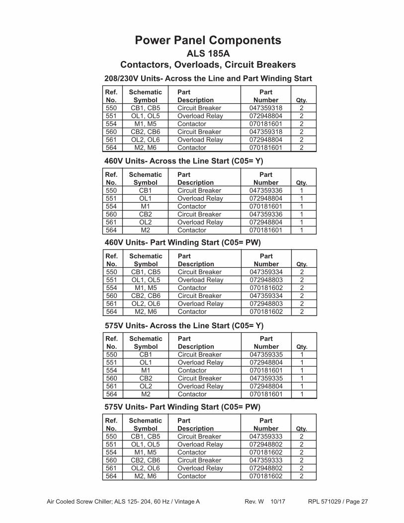
Air Cooled Screw Chiller; ALS 125- 204, 60 Hz / Vintage A Rev. W 10/17 RPL 571029 / Page 27
ALS 185AContactors, Overloads, Circuit Breakers
Power Panel Components
Ref. Schematic Part Part No. Symbol Description Number Qty. 550 CB1, CB5 Circuit Breaker 047359318 2 551 OL1, OL5 Overload Relay 072948804 2 554 M1, M5 Contactor 070181601 2 560 CB2, CB6 Circuit Breaker 047359318 2 561 OL2, OL6 Overload Relay 072948804 2 564 M2, M6 Contactor 070181601 2
208/230V Units- Across the Line and Part Winding Start
Ref. Schematic Part Part No. Symbol Description Number Qty. 550 CB1 Circuit Breaker 047359336 1 551 OL1 Overload Relay 072948804 1 554 M1 Contactor 070181601 1 560 CB2 Circuit Breaker 047359336 1 561 OL2 Overload Relay 072948804 1 564 M2 Contactor 070181601 1
460V Units- Across the Line Start (C05= Y)
Ref. Schematic Part Part No. Symbol Description Number Qty. 550 CB1, CB5 Circuit Breaker 047359334 2 551 OL1, OL5 Overload Relay 072948803 2 554 M1, M5 Contactor 070181602 2 560 CB2, CB6 Circuit Breaker 047359334 2 561 OL2, OL6 Overload Relay 072948803 2 564 M2, M6 Contactor 070181602 2
460V Units- Part Winding Start (C05= PW)
Ref. Schematic Part Part No. Symbol Description Number Qty. 550 CB1 Circuit Breaker 047359335 1 551 OL1 Overload Relay 072948804 1 554 M1 Contactor 070181601 1 560 CB2 Circuit Breaker 047359335 1 561 OL2 Overload Relay 072948804 1 564 M2 Contactor 070181601 1
575V Units- Across the Line Start (C05= Y)
Ref. Schematic Part Part No. Symbol Description Number Qty. 550 CB1, CB5 Circuit Breaker 047359333 2 551 OL1, OL5 Overload Relay 072948802 2 554 M1, M5 Contactor 070181602 2 560 CB2, CB6 Circuit Breaker 047359333 2 561 OL2, OL6 Overload Relay 072948802 2 564 M2, M6 Contactor 070181602 2
575V Units- Part Winding Start (C05= PW)
Air Cooled Screw Chiller; ALS 125- 204, 60 Hz / Vintage A Rev. W 10/17 RPL 571029 / Page 28
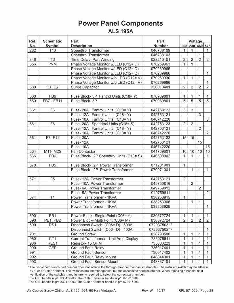
ALS 195APower Panel Components
Ref. Schematic Part Part Voltage No. Symbol Description Number 208 230 460 575 282 T10 Speedtrol Transformer 046738109 1 1 1 Speedtrol Transformer 046738103 1 346 TD Time Delay- Part Winding 028210101 2 2 2 2 356 PVM Phase Voltage Monitor w/LED (C12= D) 070269963 1 1 Phase Voltage Monitor w/LED (C12= D) 070269965 1 Phase Voltage Monitor w/LED (C12= D) 070269966 1 Phase Voltage Monitor w/o LED (C12= V) 070269930 1 1 1 Phase Voltage Monitor w/o LED (C12= V) 070269966 1 580 C1, C2 Surge Capacitor 350010401 2 2 2 2
660 FB6 Fuse Block- 3P Fantrol Units (C18= Y) 070989801 1 1 1 1 660 FB7 - FB11 Fuse Block- 3P 070989801 5 5 5 5
661 F6 Fuse- 20A Fantrol Units (C18= Y) 042753123 3 3 Fuse- 12A Fantrol Units (C18= Y) 042753121 3 Fuse- 10A Fantrol Units (C18= Y) 046742220 3 661 F6 Fuse- 20A Speedtrol Units (C18= S) 042753123 2 2 Fuse- 12A Fantrol Units (C18= Y) 042753121 2 Fuse- 10A Fantrol Units (C18= Y) 046742220 2 661 F7- F11 Fuse- 20A 042753123 15 15 Fuse- 12A 042753121 15 Fuse- 10A 046742220 15 664 M11- M25 Fan Contactor 041769601 10 10 10 10 666 FB6 Fuse Block- 2P Speedtrol Units (C18= S) 046500002 1 1 1 1
670 FB5 Fuse Block- 2P Power Transformer 071201901 1 Fuse Block- 2P Power Transformer 070971001 1 1 1
671 F5 Fuse- 12A Power Transformer 042753121 2 Fuse- 10A Power Transformer 049759816 2 Fuse- 6A Power Transformer 049759812 2 Fuse- 5A Power Transformer 049759811 2 674 T1 Power Transformer - 1KVA 038253915 1 Power Transformer - 1KVA 038253906 1 1 Power Transformer - 1KVA 038253929 1
690 PB1 Power Block- Single Point (C06= Y) 030372724 1 1 1 1 690 PB1, PB2 Power Block- Multi Point (C06= M) 030372724 2 2 2 2 690 DS1 Disconnect Switch (C06= D)- 600A 072937503* 1 1 Disconnect Switch (C06= D)- 400A 072937502* 2 1 701 Ground Screw 028798500 1 1 1 1 980 CT1 Current Transformer- Unit Amp Display 735076511 1 1 1 1 986 RES1 Resistor- 15 OHM 735003223 1 1 1 1 990 GFP Ground Fault Relay 736017401 1 1 1 1 991 Ground Fault Sensor 736017402 1 1 1 1 992 Ground Fault Relay Mount 048844301 1 1 1 1 993 Ground Fault Sensor Mount 048837101 1 1 1 1* The disconnect switch part number does not include the through-the-door mechanism (handle). The installed switch may be either a G.E. or a Cutler Hammer. The switches are interchangeable, but the associated handles are not. When replacing a handle, field verification of the switch's manufacturer is required to select the correct part number.1 The G.E. handle is p/n 330419203; The Cutler Hammer handle is p/n 073015204.2 The G.E. handle is p/n 330419203; The Cutler Hammer handle is p/n 073015203.

Air Cooled Screw Chiller; ALS 125- 204, 60 Hz / Vintage A Rev. W 10/17 RPL 571029 / Page 29
ALS 195AContactors, Overloads, Circuit Breakers
Power Panel Components
Ref. Schematic Part Part No. Symbol Description Number Qty. 550 CB1, CB5 Circuit Breaker 047359318 2 551 OL1, OL5 Overload Relay 072948804 2 554 M1, M5 Contactor 070181601 2 560 CB2, CB6 Circuit Breaker 047359318 2 561 OL2, OL6 Overload Relay 072948804 2 564 M2, M6 Contactor 070181601 2
208/230V Units- Across the Line and Part Winding Start
Ref. Schematic Part Part No. Symbol Description Number Qty. 550 CB1 Circuit Breaker 047359336 1 551 OL1 Overload Relay 072948804 1 554 M1 Contactor 070181601 1 560 CB2 Circuit Breaker 047359336 1 561 OL2 Overload Relay 072948804 1 564 M2 Contactor 070181601 1
460V Units- Across the Line Start (C05= Y)
Ref. Schematic Part Part No. Symbol Description Number Qty. 550 CB1, CB5 Circuit Breaker 047359334 2 551 OL1, OL5 Overload Relay 072948803 2 554 M1, M5 Contactor 070181602 2 560 CB2, CB6 Circuit Breaker 047359334 2 561 OL2, OL6 Overload Relay 072948803 2 564 M2, M6 Contactor 070181602 2
460V Units- Part Winding Start (C05= PW)
Ref. Schematic Part Part No. Symbol Description Number Qty. 550 CB1 Circuit Breaker 047359335 1 551 OL1 Overload Relay 072948804 1 554 M1 Contactor 070181601 1 560 CB2 Circuit Breaker 047359335 1 561 OL2 Overload Relay 072948804 1 564 M2 Contactor 070181601 1
575V Units- Across the Line Start (C05= Y)
Ref. Schematic Part Part No. Symbol Description Number Qty. 550 CB1, CB5 Circuit Breaker 047359333 2 551 OL1, OL5 Overload Relay 072948802 2 554 M1, M5 Contactor 070181602 2 560 CB2, CB6 Circuit Breaker 047359333 2 561 OL2, OL6 Overload Relay 072948802 2 564 M2, M6 Contactor 070181602 2
575V Units- Part Winding Start (C05= PW)
Air Cooled Screw Chiller; ALS 125- 204, 60 Hz / Vintage A Rev. W 10/17 RPL 571029 / Page 30
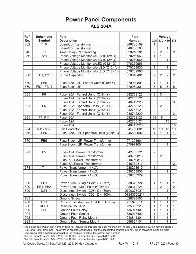
ALS 204APower Panel Components
Ref. Schematic Part Part Voltage No. Symbol Description Number 208 230 460 575 282 T10 Speedtrol Transformer 046738109 1 1 1 Speedtrol Transformer 046738103 1 346 TD Time Delay- Part Winding 028210101 2 2 2 2 356 PVM Phase Voltage Monitor w/LED (C12= D) 070269963 1 1 Phase Voltage Monitor w/LED (C12= D) 070269965 1 Phase Voltage Monitor w/LED (C12= D) 070269966 1 Phase Voltage Monitor w/o LED (C12= V) 070269930 1 1 1 Phase Voltage Monitor w/o LED (C12= V) 070269966 1 580 C1, C2 Surge Capacitor 350010401 2 2 2 2
660 FB6 Fuse Block- 3P Fantrol Units (C18= Y) 070989801 1 1 1 1 660 FB7 - FB11 Fuse Block- 3P 070989801 5 5 5 5
661 F6 Fuse- 20A Fantrol Units (C18= Y) 042753123 3 3 Fuse- 12A Fantrol Units (C18= Y) 042753121 3 Fuse- 10A Fantrol Units (C18= Y) 046742220 3 661 F6 Fuse- 20A Speedtrol Units (C18= S) 042753123 2 2 Fuse- 12A Fantrol Units (C18= Y) 042753121 2 Fuse- 10A Fantrol Units (C18= Y) 046742220 2 661 F7- F11 Fuse- 20A 042753123 15 15 Fuse- 12A 042753121 15 Fuse- 10A 046742220 15 664 M11- M25 Fan Contactor 041769601 10 10 10 10 666 FB6 Fuse Block- 2P Speedtrol Units (C18= S) 046500002 1 1 1 1
670 FB5 Fuse Block- 2P Power Transformer 071201901 1 Fuse Block- 2P Power Transformer 070971001 1 1 1
671 F5 Fuse- 12A Power Transformer 042753121 2 Fuse- 10A Power Transformer 049759816 2 Fuse- 6A Power Transformer 049759812 2 Fuse- 5A Power Transformer 049759811 2 674 T1 Power Transformer - 1KVA 038253915 1 Power Transformer - 1KVA 038253906 1 1 Power Transformer - 1KVA 038253929 1
690 PB1 Power Block- Single Point (C06= Y) 030372724 1 1 1 1 690 PB1, PB2 Power Block- Multi Point (C06= M) 030372724 2 2 2 2 690 DS1 Disconnect Switch (C06= D)- 600A 072937503* 1 1 Disconnect Switch (C06= D)- 400A 072937502* 2 1 701 Ground Screw 028798500 1 1 1 1 980 CT1 Current Transformer- Unit Amp Display 735076511 1 1 1 1 986 RES1 Resistor- 15 OHM 735003223 1 1 1 1 990 GFP Ground Fault Relay 736017401 1 1 1 1 991 Ground Fault Sensor 736017402 1 1 1 1 992 Ground Fault Relay Mount 048844301 1 1 1 1 993 Ground Fault Sensor Mount 048837101 1 1 1 1
* The disconnect switch part number does not include the through-the-door mechanism (handle). The installed switch may be either a G.E. or a Cutler Hammer. The switches are interchangeable, but the associated handles are not. When replacing a handle, field verification of the switch's manufacturer is required to select the correct part number.1 The G.E. handle is p/n 330419203; The Cutler Hammer handle is p/n 073015204.2 The G.E. handle is p/n 330419203; The Cutler Hammer handle is p/n 073015203.

Air Cooled Screw Chiller; ALS 125- 204, 60 Hz / Vintage A Rev. W 10/17 RPL 571029 / Page 31
ALS 204AContactors, Overloads, Circuit Breakers
Power Panel Components
Ref. Schematic Part Part No. Symbol Description Number Qty. 550 CB1, CB5 Circuit Breaker 047359318 2 551 OL1, OL5 Overload Relay 072948804 2 554 M1, M5 Contactor 070181601 2 560 CB2, CB6 Circuit Breaker 047359318 2 561 OL2, OL6 Overload Relay 072948804 2 564 M2, M6 Contactor 070181601 2
208/230V Units- Across the Line and Part Winding Start
Ref. Schematic Part Part No. Symbol Description Number Qty. 550 CB1 Circuit Breaker 047359336 1 551 OL1 Overload Relay 072948804 1 554 M1 Contactor 070181601 1 560 CB2 Circuit Breaker 047359336 1 561 OL2 Overload Relay 072948804 1 564 M2 Contactor 070181601 1
460V Units- Across the Line Start (C05= Y)
Ref. Schematic Part Part No. Symbol Description Number Qty. 550 CB1, CB5 Circuit Breaker 047359334 2 551 OL1, OL5 Overload Relay 072948803 2 554 M1, M5 Contactor 070181602 2 560 CB2, CB6 Circuit Breaker 047359334 2 561 OL2, OL6 Overload Relay 072948803 2 564 M2, M6 Contactor 070181602 2
460V Units- Part Winding Start (C05= PW)
Ref. Schematic Part Part No. Symbol Description Number Qty. 550 CB1 Circuit Breaker 047359335 1 551 OL1 Overload Relay 072948804 1 554 M1 Contactor 070181601 1 560 CB2 Circuit Breaker 047359335 1 561 OL2 Overload Relay 072948804 1 564 M2 Contactor 070181601 1
575V Units- Across the Line Start (C05= Y)
Ref. Schematic Part Part No. Symbol Description Number Qty. 550 CB1, CB5 Circuit Breaker 047359333 2 551 OL1, OL5 Overload Relay 072948802 2 554 M1, M5 Contactor 070181602 2 560 CB2, CB6 Circuit Breaker 047359333 2 561 OL2, OL6 Overload Relay 072948802 2 564 M2, M6 Contactor 070181602 2
575V Units- Part Winding Start (C05= PW)
Air Cooled Screw Chiller; ALS 125- 204, 60 Hz / Vintage A Rev. W 10/17 RPL 571029 / Page 32
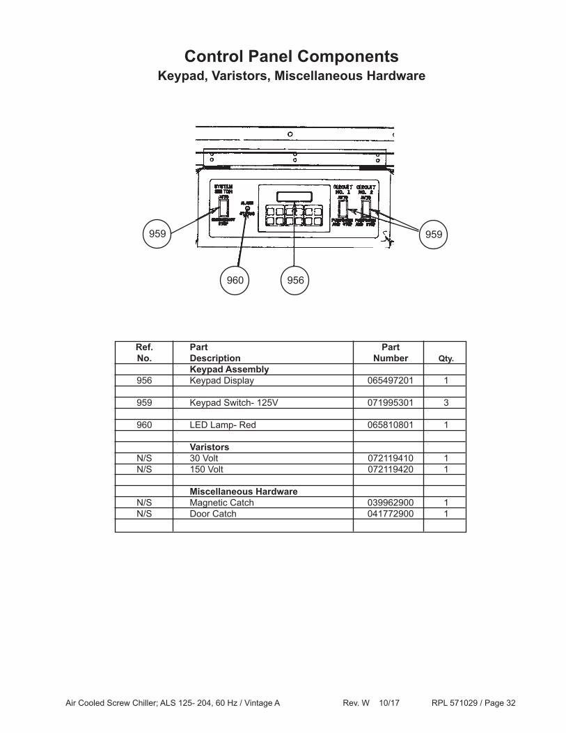
Keypad, Varistors, Miscellaneous HardwareControl Panel Components
Ref. Part Part No. Description Number Qty. Keypad Assembly 956 Keypad Display 065497201 1
959 Keypad Switch- 125V 071995301 3
960 LED Lamp- Red 065810801 1
Varistors N/S 30 Volt 072119410 1 N/S 150 Volt 072119420 1
Miscellaneous Hardware N/S Magnetic Catch 039962900 1 N/S Door Catch 041772900 1
959
956960
959
Air Cooled Screw Chiller; ALS 125- 204, 60 Hz / Vintage A Rev. W 10/17 RPL 571029 / Page 33
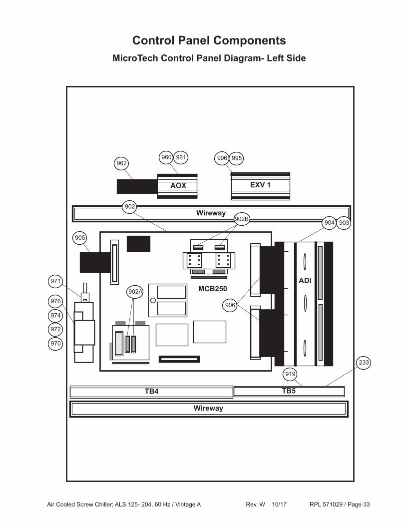
Control Panel ComponentsMicroTech Control Panel Diagram- Left Side
Wireway
TB4
Wireway
TB5
AOX EXV 1
906
MCB250ADI
905
976
974
972
970
971
962
919
960 961 996 995
904 903
233
902
902B
902A
Air Cooled Screw Chiller; ALS 125- 204, 60 Hz / Vintage A Rev. W 10/17 RPL 571029 / Page 34
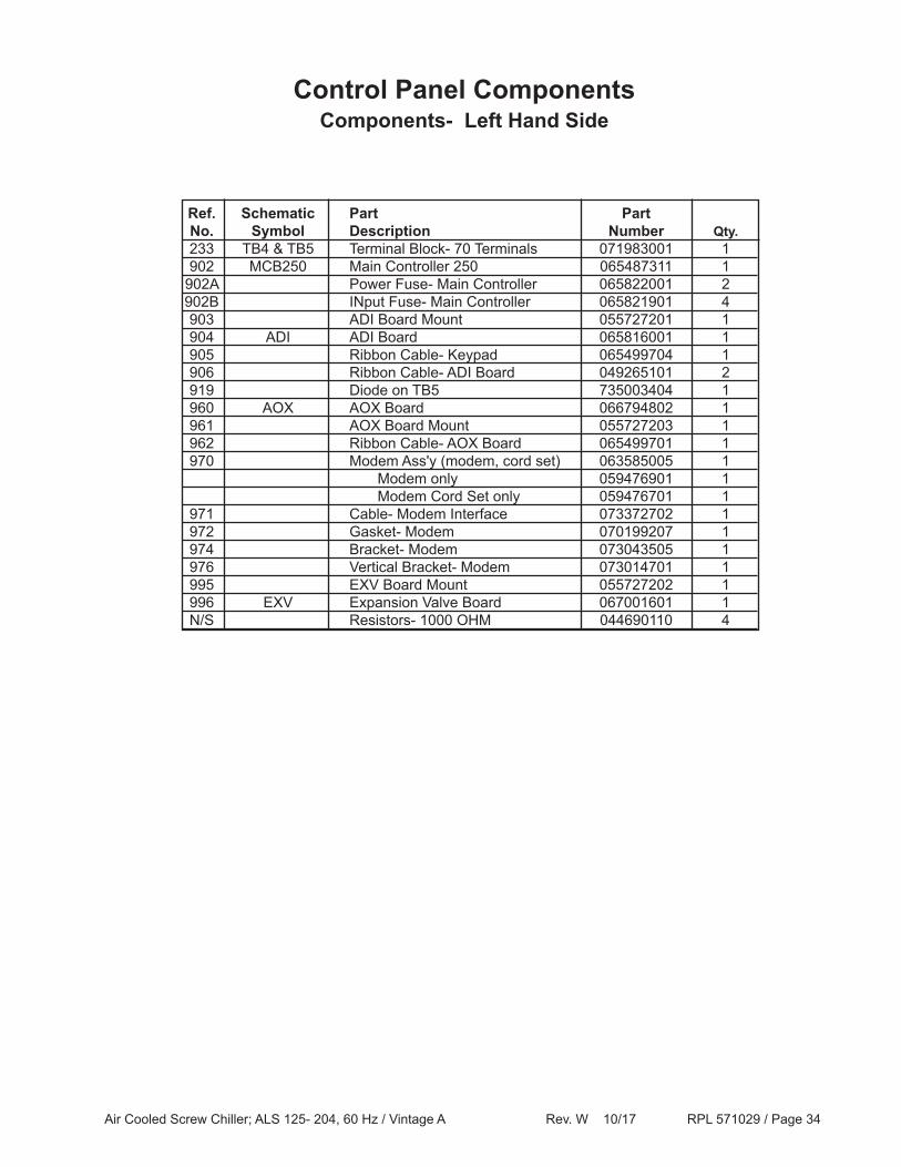
Components- Left Hand SideControl Panel Components
Ref. Schematic Part Part No. Symbol Description Number Qty. 233 TB4 & TB5 Terminal Block- 70 Terminals 071983001 1 902 MCB250 Main Controller 250 065487311 1 902A Power Fuse- Main Controller 065822001 2 902B INput Fuse- Main Controller 065821901 4 903 ADI Board Mount 055727201 1 904 ADI ADI Board 065816001 1 905 Ribbon Cable- Keypad 065499704 1 906 Ribbon Cable- ADI Board 049265101 2 919 Diode on TB5 735003404 1 960 AOX AOX Board 066794802 1 961 AOX Board Mount 055727203 1 962 Ribbon Cable- AOX Board 065499701 1 970 Modem Ass'y (modem, cord set) 063585005 1 Modem only 059476901 1 Modem Cord Set only 059476701 1 971 Cable- Modem Interface 073372702 1 972 Gasket- Modem 070199207 1 974 Bracket- Modem 073043505 1 976 Vertical Bracket- Modem 073014701 1 995 EXV Board Mount 055727202 1 996 EXV Expansion Valve Board 067001601 1 N/S Resistors- 1000 OHM 044690110 4
Air Cooled Screw Chiller; ALS 125- 204, 60 Hz / Vintage A Rev. W 10/17 RPL 571029 / Page 35
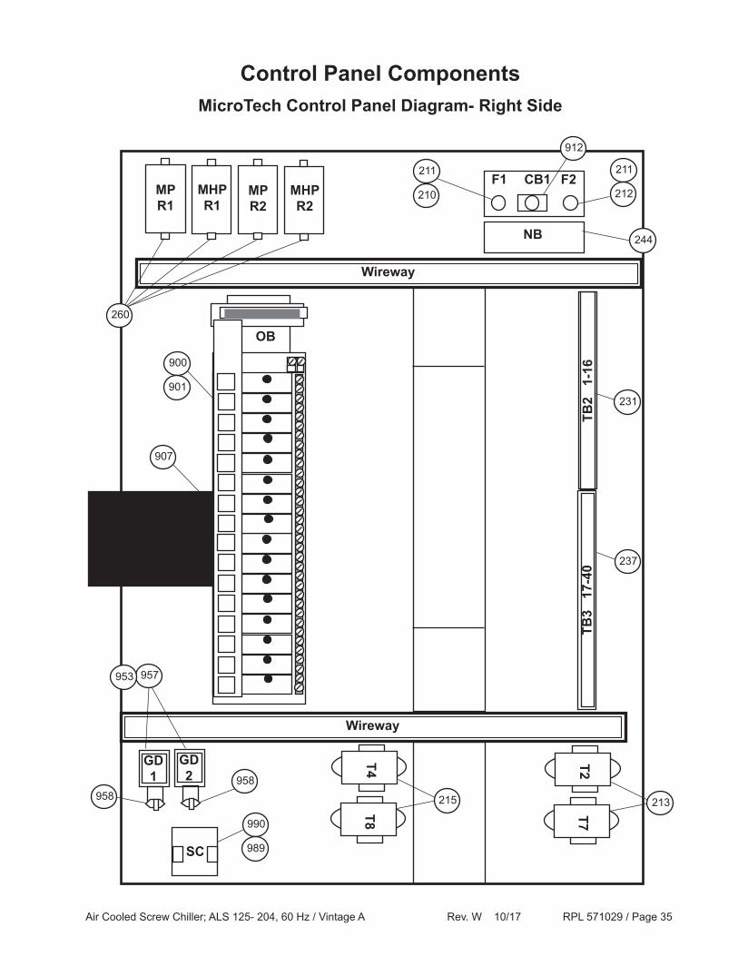
Control Panel ComponentsMicroTech Control Panel Diagram- Right Side
Wireway
TB3
17-
40TB
2 1
-16900
901
MPR1
MHPR1
SC
Wireway
907
NB
F1 F2CB1
T2T7
T4T8
GD1 958
MPR2
MHPR2
GD2
958
260
211
210
211
212
912
244
231
237
213215
957953
990
989
OB
Air Cooled Screw Chiller; ALS 125- 204, 60 Hz / Vintage A Rev. W 10/17 RPL 571029 / Page 36
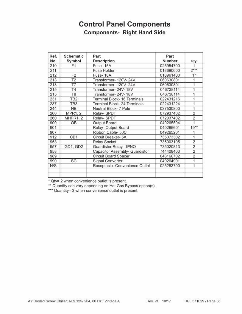
Components- Right Hand SideControl Panel Components
Ref. Schematic Part Part No. Symbol Description Number Qty. 210 F1 Fuse- 15A 025954700 1 211 Fuse Holder 018690600 2*** 212 F2 Fuse- 10A 018961400 1* 213 T2 Transformer- 120V- 24V 060630801 1 213 T7 Transformer- 120V- 24V 060630801 1 215 T4 Transformer- 24V- 18V 046738114 1 215 T8 Transformer- 24V- 18V 046738114 1 231 TB2 Terminal Block- 16 Terminals 022431216 1 237 TB3 Terminal Block- 24 Terminals 022431224 1 244 NB Neutral Block- 7 Pole 037530800 1 260 MPR1, 2 Relay- SPDT 072937402 2 260 MHPR1, 2 Relay- SPDT 072937402 2 900 OB Output Board 049265504 1 901 Relay- Output Board 049265601 19** 907 Ribbon Cable- 50C 049265201 1 912 CB1 Circuit Breaker- 5A 735073302 1 953 Relay Socket 735003105 2 957 GD1, GD2 Guardistor Relay- 1PNO 735020813 2 958 Capacitor Assembly- Guardistor 744408403 2 989 Circuit Board Spacer 048166702 2 990 SC Signal Converter 049264901 1 N/S Receptacle- Convenience Outlet 025283700 1
* Qty= 2 when convenience outlet is present.** Quantity can vary depending on Hot Gas Bypass option(s).*** Quantity= 3 when convenience outlet is present.
Air Cooled Screw Chiller; ALS 125- 204, 60 Hz / Vintage A Rev. W 10/17 RPL 571029 / Page 37
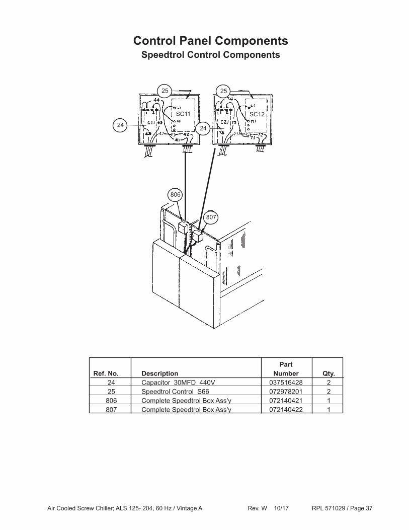
Speedtrol Control ComponentsControl Panel Components
25 25
24 24
806
807
Part Ref. No. Description Number Qty. 24 Capacitor 30MFD 440V 037516428 2 25 Speedtrol Control S66 072978201 2 806 Complete Speedtrol Box Ass'y 072140421 1 807 Complete Speedtrol Box Ass'y 072140422 1
SC11 SC12
Air Cooled Screw Chiller; ALS 125- 204, 60 Hz / Vintage A Rev. W 10/17 RPL 571029 / Page 38
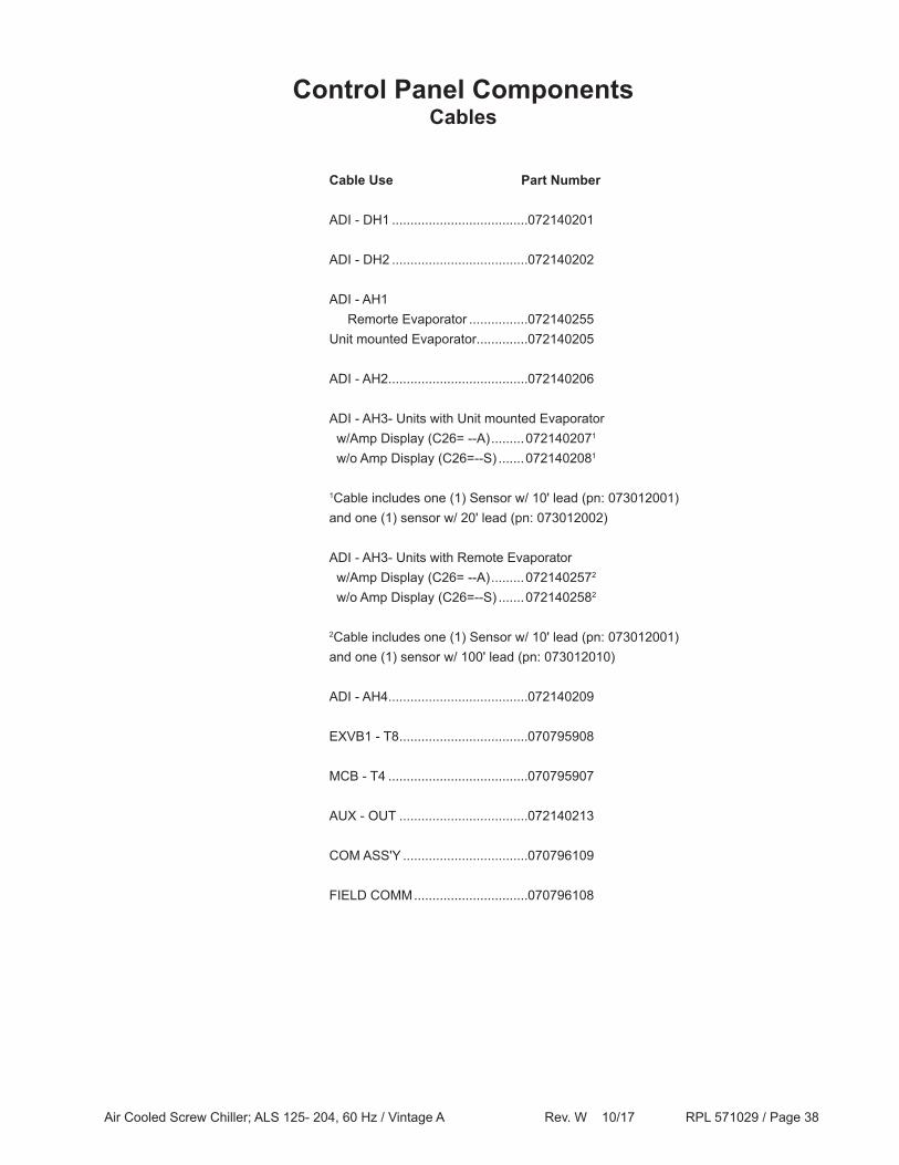
Control Panel ComponentsCables
Cable Use Part Number
ADI - DH1 .....................................072140201
ADI - DH2 .....................................072140202
ADI - AH1 Remorte Evaporator ................072140255 Unit mounted Evaporator..............072140205
ADI - AH2......................................072140206
ADI - AH3- Units with Unit mounted Evaporator w/Amp Display (C26= --A) .........0721402071
w/o Amp Display (C26=--S) .......0721402081
1Cable includes one (1) Sensor w/ 10' lead (pn: 073012001) and one (1) sensor w/ 20' lead (pn: 073012002)
ADI - AH3- Units with Remote Evaporator w/Amp Display (C26= --A) .........0721402572
w/o Amp Display (C26=--S) .......0721402582
2Cable includes one (1) Sensor w/ 10' lead (pn: 073012001) and one (1) sensor w/ 100' lead (pn: 073012010)
ADI - AH4......................................072140209
EXVB1 - T8 ...................................070795908
MCB - T4 ......................................070795907
AUX - OUT ...................................072140213
COM ASS'Y ..................................070796109
FIELD COMM ...............................070796108
Air Cooled Screw Chiller; ALS 125- 204, 60 Hz / Vintage A Rev. W 10/17 RPL 571029 / Page 39
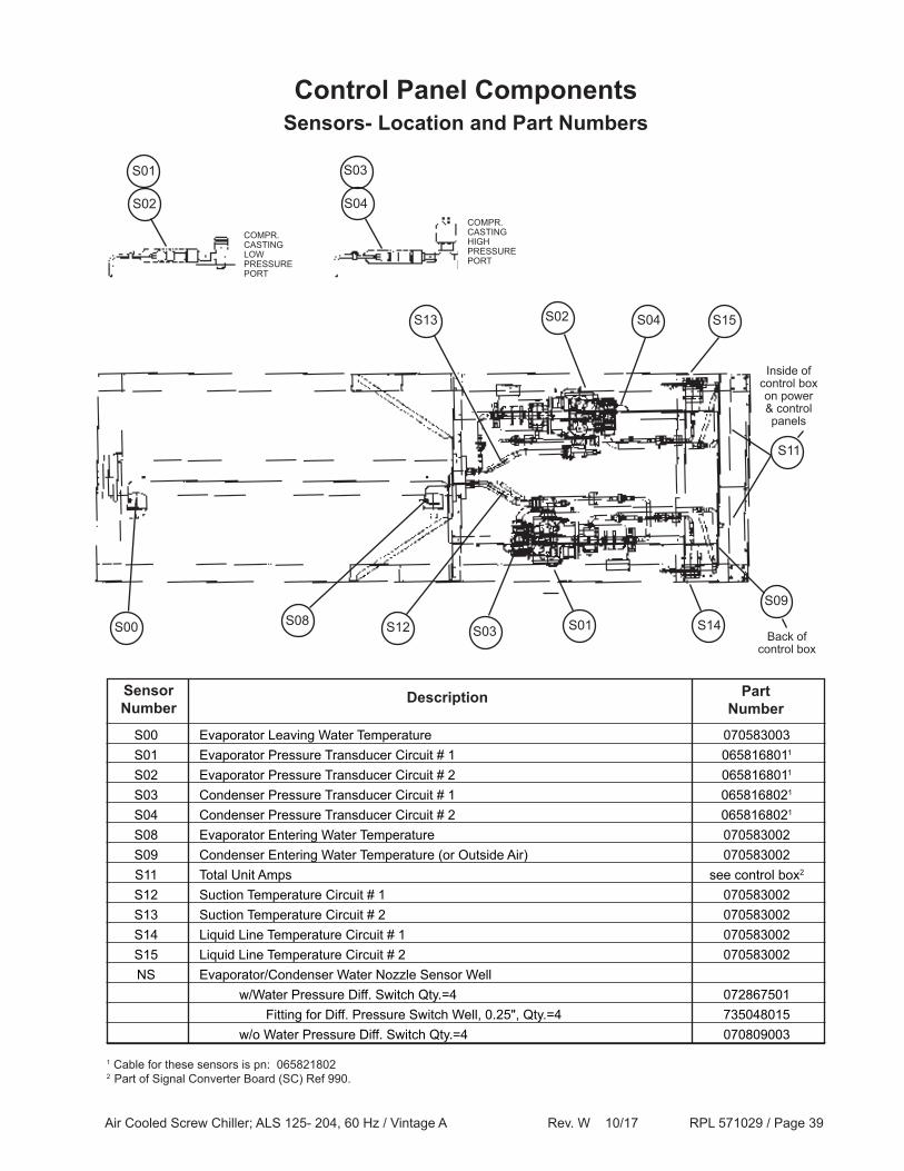
S00 Evaporator Leaving Water Temperature 070583003 S01 Evaporator Pressure Transducer Circuit # 1 0658168011
S02 Evaporator Pressure Transducer Circuit # 2 0658168011
S03 Condenser Pressure Transducer Circuit # 1 0658168021
S04 Condenser Pressure Transducer Circuit # 2 0658168021
S08 Evaporator Entering Water Temperature 070583002 S09 Condenser Entering Water Temperature (or Outside Air) 070583002 S11 Total Unit Amps see control box2
S12 Suction Temperature Circuit # 1 070583002 S13 Suction Temperature Circuit # 2 070583002 S14 Liquid Line Temperature Circuit # 1 070583002 S15 Liquid Line Temperature Circuit # 2 070583002 NS Evaporator/Condenser Water Nozzle Sensor Well w/Water Pressure Diff. Switch Qty.=4 072867501 Fitting for Diff. Pressure Switch Well, 0.25", Qty.=4 735048015 w/o Water Pressure Diff. Switch Qty.=4 070809003
PartNumber
SensorNumber
Description
1 Cable for these sensors is pn: 065821802 2 Part of Signal Converter Board (SC) Ref 990.
Control Panel ComponentsSensors- Location and Part Numbers
S02
COMPR.CASTINGLOWPRESSUREPORT
COMPR.CASTINGHIGHPRESSUREPORT
S01 S03
S04
S11
S09
S03 S01 S14
S15S04S13 S02
S12S08S00
Inside of control box on power& control panels
Back ofcontrol box
Air Cooled Screw Chiller; ALS 125- 204, 60 Hz / Vintage A Rev. W 10/17 RPL 571029 / Page 40
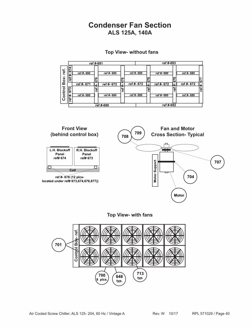
Condenser Fan SectionALS 125A, 140A
701
648typ.
Top View- with fans
Top View- without fans
7008 plcs.
713typ.
Con
trol
Box
- ref
.
Front View(behind control box)
Coil
ref #- 678 (12 plcs- located under ref# 673,674,676,677))
L.H. Blockoff Panel
ref# 674
R.H. Blockoff Panel
ref# 673
ref #- 671
ref #
- 676
ref #- 672
ref #
- 676
ref #- 672
ref #
- 676
ref #-690
ref #- 680
ref #- 680
ref #- 680
ref #- 680
ref #- 680
ref #- 680
ref #
- 673
ref #
- 674
Con
trol
Box
- ref
.
ref #- 672
ref #
- 677
ref #- 680
ref #- 680
ref #-692
ref #-691 ref #-693
ref #
- 676
ref #- 672
ref #- 680
ref #- 680
707
Motor
704
Mot
or S
uppo
rt
Fan and Motor Cross Section- Typical708
709
Air Cooled Screw Chiller; ALS 125- 204, 60 Hz / Vintage A Rev. W 10/17 RPL 571029 / Page 41
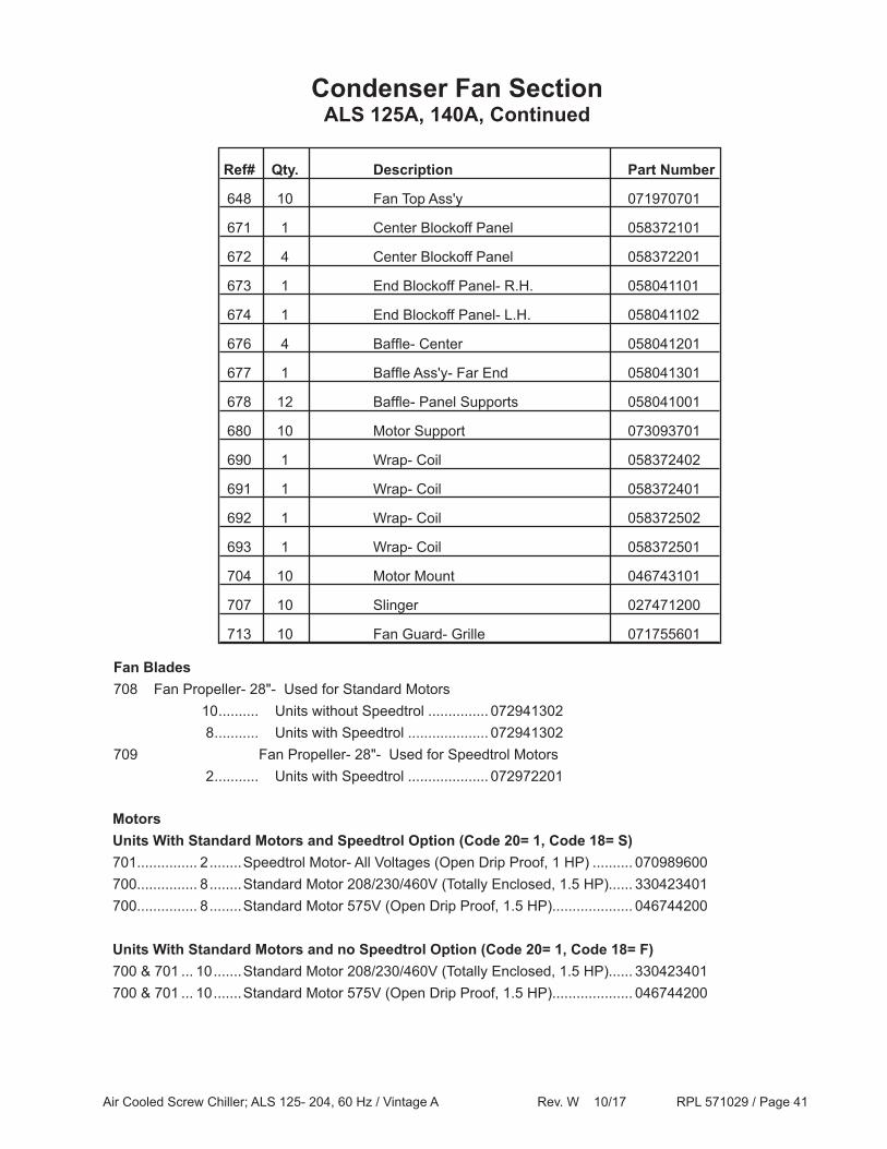
Ref# Qty. Description Part Number
648 10 Fan Top Ass'y 071970701
671 1 Center Blockoff Panel 058372101
672 4 Center Blockoff Panel 058372201
673 1 End Blockoff Panel- R.H. 058041101
674 1 End Blockoff Panel- L.H. 058041102
676 4 Baffle- Center 058041201
677 1 Baffle Ass'y- Far End 058041301
678 12 Baffle- Panel Supports 058041001
680 10 Motor Support 073093701
690 1 Wrap- Coil 058372402
691 1 Wrap- Coil 058372401
692 1 Wrap- Coil 058372502
693 1 Wrap- Coil 058372501
704 10 Motor Mount 046743101
707 10 Slinger 027471200
713 10 Fan Guard- Grille 071755601
Condenser Fan SectionALS 125A, 140A, Continued
MotorsUnits With Standard Motors and Speedtrol Option (Code 20= 1, Code 18= S)701............... 2 ........Speedtrol Motor- All Voltages (Open Drip Proof, 1 HP) .......... 070989600700............... 8 ........Standard Motor 208/230/460V (Totally Enclosed, 1.5 HP)...... 330423401700............... 8 ........Standard Motor 575V (Open Drip Proof, 1.5 HP).................... 046744200
Units With Standard Motors and no Speedtrol Option (Code 20= 1, Code 18= F)700 & 701 ... 10 .......Standard Motor 208/230/460V (Totally Enclosed, 1.5 HP)...... 330423401700 & 701 ... 10 .......Standard Motor 575V (Open Drip Proof, 1.5 HP).................... 046744200
Fan Blades708 Fan Propeller- 28"- Used for Standard Motors 10 .......... Units without Speedtrol ............... 072941302 8 ........... Units with Speedtrol .................... 072941302709 Fan Propeller- 28"- Used for Speedtrol Motors 2 ........... Units with Speedtrol .................... 072972201
Air Cooled Screw Chiller; ALS 125- 204, 60 Hz / Vintage A Rev. W 10/17 RPL 571029 / Page 42
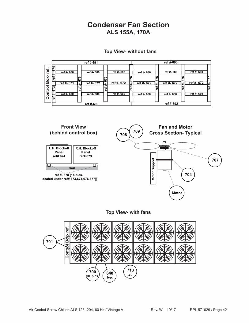
Condenser Fan SectionALS 155A, 170A
Top View- without fans
Front View(behind control box)
Coil
ref #- 678 (14 plcs- located under ref# 673,674,676,677))
L.H. Blockoff Panel
ref# 674
R.H. Blockoff Panel
ref# 673
ref #- 671re
f #- 6
76ref #- 672
ref #
- 676
ref #- 672
ref #
- 676
ref #-690
ref #- 680
ref #- 680
ref #- 680
ref #- 680
ref #- 680
ref #- 680
ref #
- 673
ref #
- 674
Con
trol
Box
- ref
.
ref #- 672
ref #
- 677
ref #- 680
ref #- 680
ref #-692
ref #-691 ref #-693
ref #
- 676
ref #- 672
ref #- 680
ref #- 680
ref #
- 676
ref #- 672
ref #- 680
ref #- 680
707
Motor
704
Mot
or S
uppo
rt
Fan and Motor Cross Section- Typical708
709
701
648typ.
Top View- with fans
70010 plcs.
713typ.
Con
trol
Box
- ref
.
Air Cooled Screw Chiller; ALS 125- 204, 60 Hz / Vintage A Rev. W 10/17 RPL 571029 / Page 43
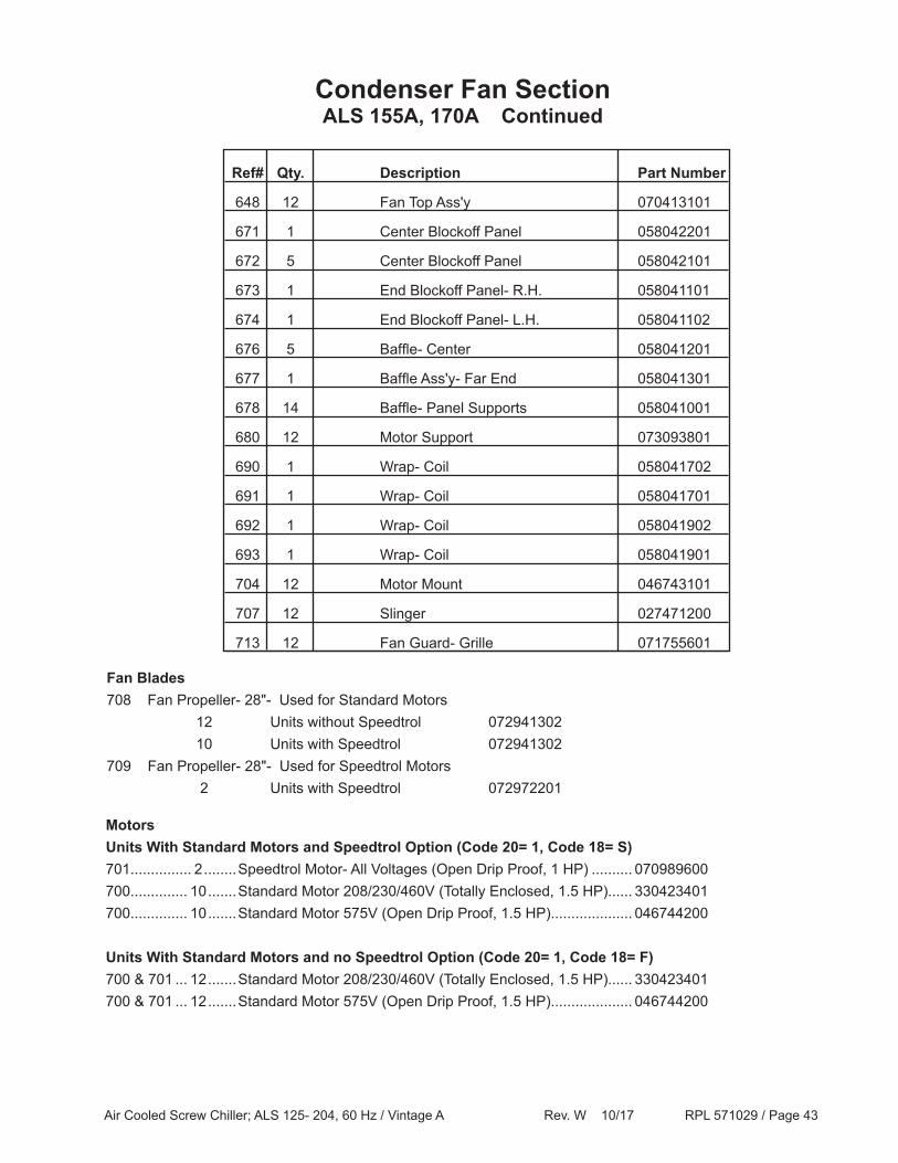
Ref# Qty. Description Part Number
648 12 Fan Top Ass'y 070413101
671 1 Center Blockoff Panel 058042201
672 5 Center Blockoff Panel 058042101
673 1 End Blockoff Panel- R.H. 058041101
674 1 End Blockoff Panel- L.H. 058041102
676 5 Baffle- Center 058041201
677 1 Baffle Ass'y- Far End 058041301
678 14 Baffle- Panel Supports 058041001
680 12 Motor Support 073093801
690 1 Wrap- Coil 058041702
691 1 Wrap- Coil 058041701
692 1 Wrap- Coil 058041902
693 1 Wrap- Coil 058041901
704 12 Motor Mount 046743101
707 12 Slinger 027471200
713 12 Fan Guard- Grille 071755601
Condenser Fan SectionALS 155A, 170A Continued
MotorsUnits With Standard Motors and Speedtrol Option (Code 20= 1, Code 18= S)701............... 2 ........Speedtrol Motor- All Voltages (Open Drip Proof, 1 HP) .......... 070989600700.............. 10 .......Standard Motor 208/230/460V (Totally Enclosed, 1.5 HP)...... 330423401700.............. 10 .......Standard Motor 575V (Open Drip Proof, 1.5 HP).................... 046744200
Units With Standard Motors and no Speedtrol Option (Code 20= 1, Code 18= F)700 & 701 ... 12 .......Standard Motor 208/230/460V (Totally Enclosed, 1.5 HP)...... 330423401700 & 701 ... 12 .......Standard Motor 575V (Open Drip Proof, 1.5 HP).................... 046744200
Fan Blades708 Fan Propeller- 28"- Used for Standard Motors 12 Units without Speedtrol 072941302 10 Units with Speedtrol 072941302709 Fan Propeller- 28"- Used for Speedtrol Motors 2 Units with Speedtrol 072972201
Air Cooled Screw Chiller; ALS 125- 204, 60 Hz / Vintage A Rev. W 10/17 RPL 571029 / Page 44
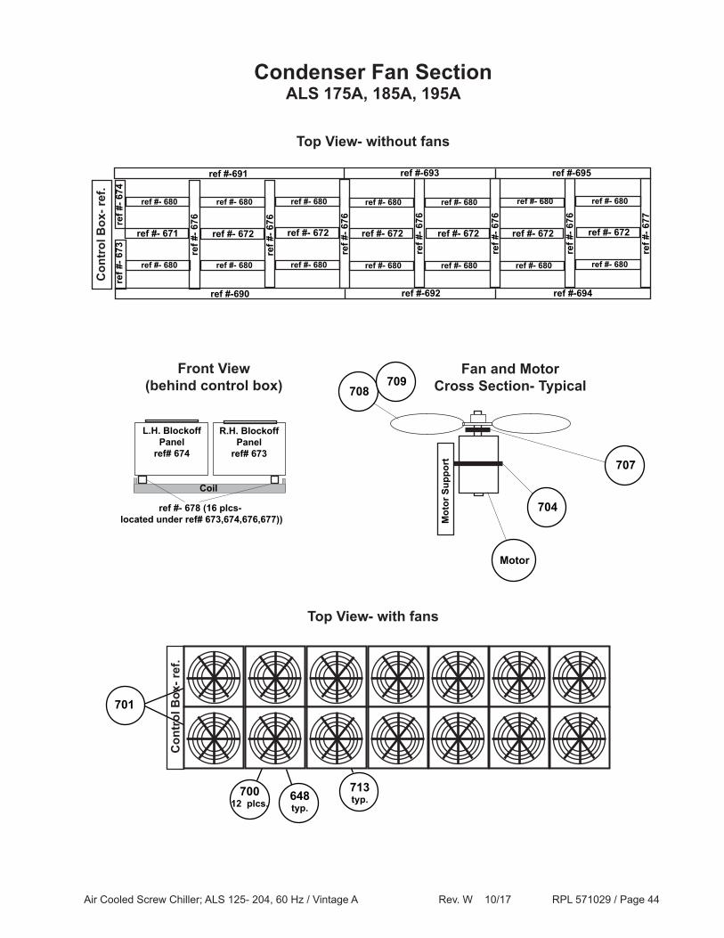
Condenser Fan SectionALS 175A, 185A, 195A
Top View- without fans
ref #- 671
ref #
- 676
ref #- 672
ref #
- 676
ref #- 672
ref #
- 676
ref #-690
ref #- 680
ref #- 680
ref #- 680
ref #- 680
ref #- 680
ref #- 680
ref #
- 673
ref #
- 674
Con
trol
Box
- ref
.
ref #- 672
ref #
- 677
ref #- 680
ref #- 680
ref #-692
ref #-691 ref #-693
ref #
- 676
ref #- 672
ref #- 680
ref #- 680
ref #
- 676
ref #- 672
ref #- 680
ref #- 680
ref #
- 676
ref #- 672
ref #- 680
ref #- 680
ref #-694
ref #-695
707
Motor
704
Mot
or S
uppo
rt
Fan and Motor Cross Section- Typical708
709Front View
(behind control box)
Coil
ref #- 678 (16 plcs- located under ref# 673,674,676,677))
L.H. Blockoff Panel
ref# 674
R.H. Blockoff Panel
ref# 673
701
648typ.
Top View- with fans
70012 plcs.
713typ.
Con
trol
Box
- ref
.
Air Cooled Screw Chiller; ALS 125- 204, 60 Hz / Vintage A Rev. W 10/17 RPL 571029 / Page 45
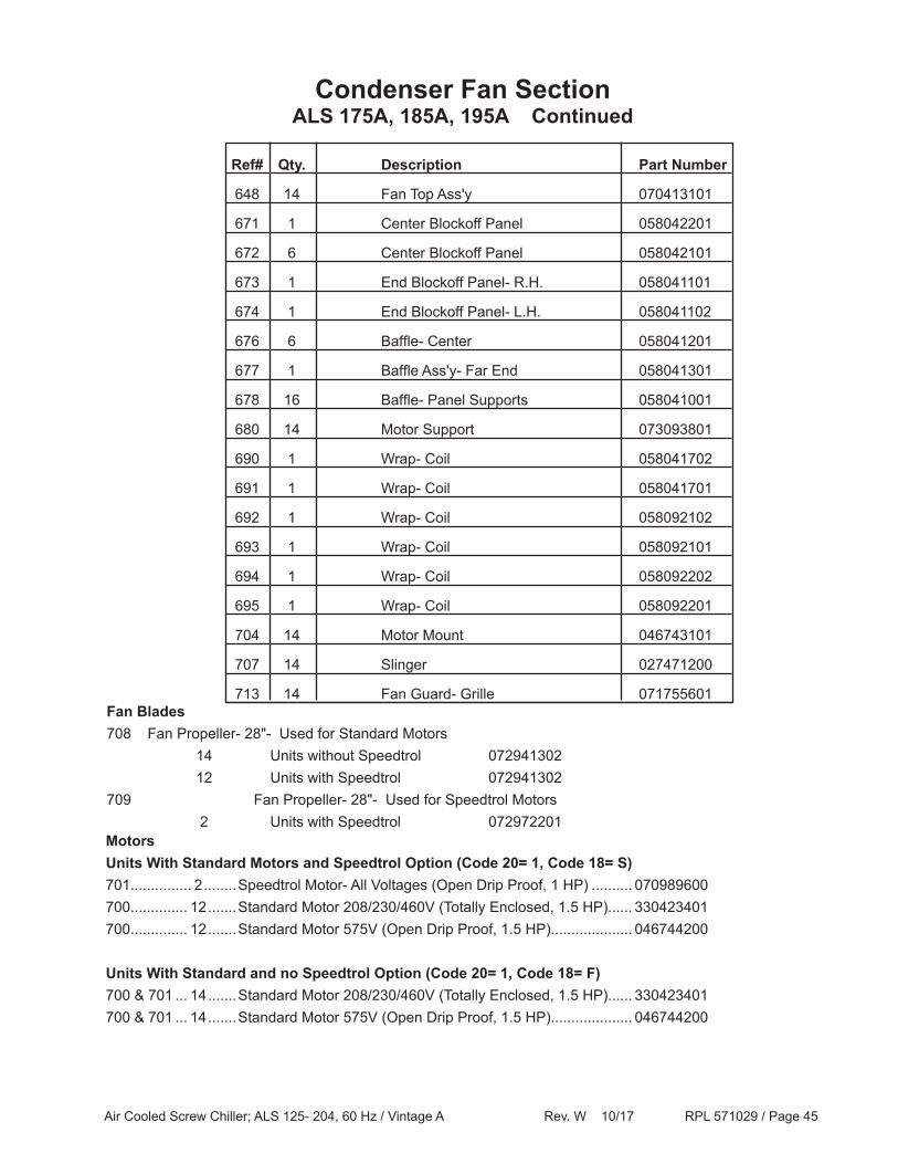
Ref# Qty. Description Part Number
648 14 Fan Top Ass'y 070413101
671 1 Center Blockoff Panel 058042201
672 6 Center Blockoff Panel 058042101
673 1 End Blockoff Panel- R.H. 058041101
674 1 End Blockoff Panel- L.H. 058041102
676 6 Baffle- Center 058041201
677 1 Baffle Ass'y- Far End 058041301
678 16 Baffle- Panel Supports 058041001
680 14 Motor Support 073093801
690 1 Wrap- Coil 058041702
691 1 Wrap- Coil 058041701
692 1 Wrap- Coil 058092102
693 1 Wrap- Coil 058092101
694 1 Wrap- Coil 058092202
695 1 Wrap- Coil 058092201
704 14 Motor Mount 046743101
707 14 Slinger 027471200
713 14 Fan Guard- Grille 071755601
Condenser Fan SectionALS 175A, 185A, 195A Continued
MotorsUnits With Standard Motors and Speedtrol Option (Code 20= 1, Code 18= S)701............... 2 ........Speedtrol Motor- All Voltages (Open Drip Proof, 1 HP) .......... 070989600700.............. 12 .......Standard Motor 208/230/460V (Totally Enclosed, 1.5 HP)...... 330423401700.............. 12 .......Standard Motor 575V (Open Drip Proof, 1.5 HP).................... 046744200
Units With Standard and no Speedtrol Option (Code 20= 1, Code 18= F)700 & 701 ... 14 .......Standard Motor 208/230/460V (Totally Enclosed, 1.5 HP)...... 330423401700 & 701 ... 14 .......Standard Motor 575V (Open Drip Proof, 1.5 HP).................... 046744200
Fan Blades708 Fan Propeller- 28"- Used for Standard Motors 14 Units without Speedtrol 072941302 12 Units with Speedtrol 072941302709 Fan Propeller- 28"- Used for Speedtrol Motors 2 Units with Speedtrol 072972201
Air Cooled Screw Chiller; ALS 125- 204, 60 Hz / Vintage A Rev. W 10/17 RPL 571029 / Page 46
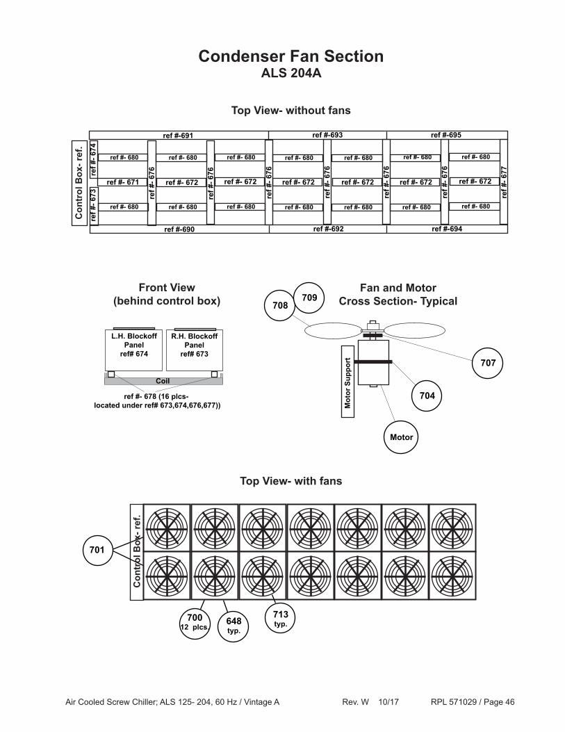
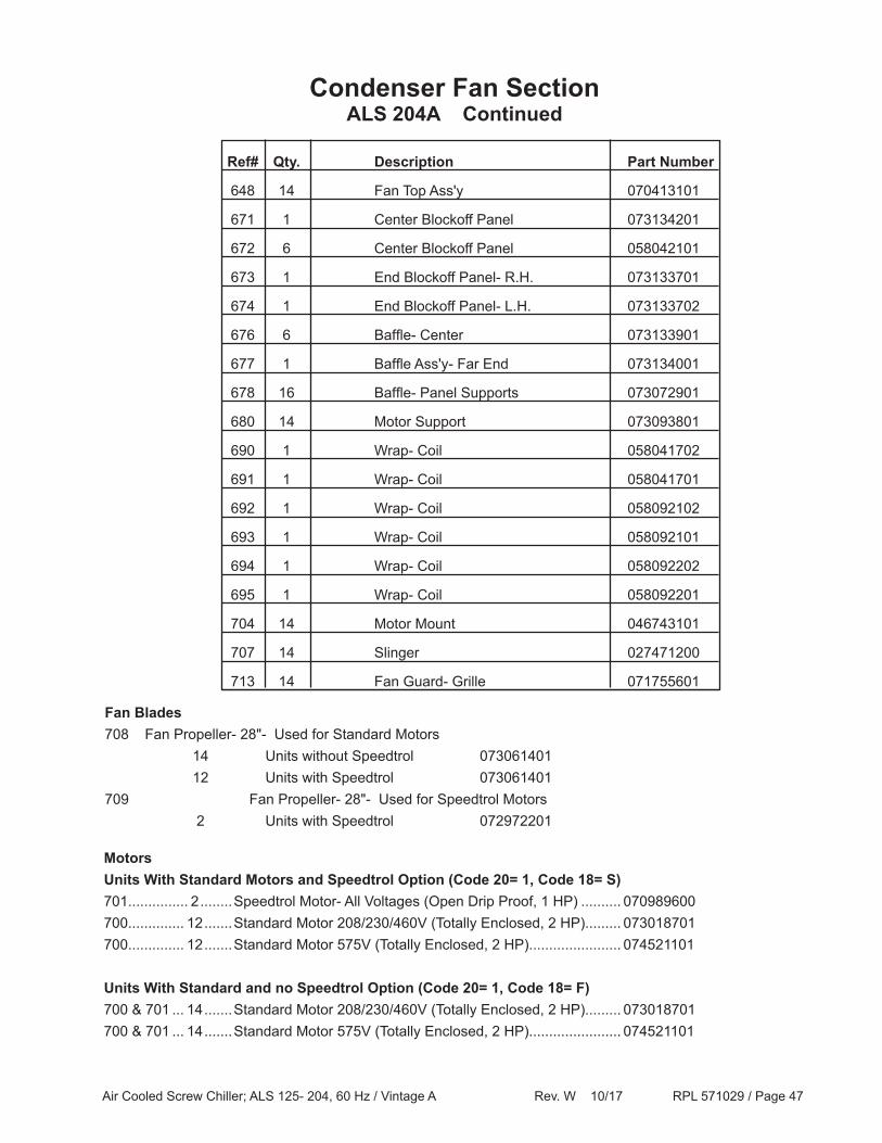
Condenser Fan SectionALS 204A
Top View- without fans
ref #- 671
ref #
- 676
ref #- 672
ref #
- 676
ref #- 672
ref #
- 676
ref #-690
ref #- 680
ref #- 680
ref #- 680
ref #- 680
ref #- 680
ref #- 680
ref #
- 673
ref #
- 674
Con
trol
Box
- ref
.
ref #- 672
ref #
- 677
ref #- 680
ref #- 680
ref #-692
ref #-691 ref #-693
ref #
- 676
ref #- 672
ref #- 680
ref #- 680
ref #
- 676
ref #- 672
ref #- 680
ref #- 680
ref #
- 676
ref #- 672
ref #- 680
ref #- 680
ref #-694
ref #-695
Front View(behind control box)
Coil
ref #- 678 (16 plcs- located under ref# 673,674,676,677))
L.H. Blockoff Panel
ref# 674
R.H. Blockoff Panel
ref# 673707
Motor
704
Mot
or S
uppo
rt
Fan and Motor Cross Section- Typical708
709
701
648typ.
Top View- with fans
70012 plcs.
713typ.
Con
trol
Box
- ref
.
Air Cooled Screw Chiller; ALS 125- 204, 60 Hz / Vintage A Rev. W 10/17 RPL 571029 / Page 47
Ref# Qty. Description Part Number
648 14 Fan Top Ass'y 070413101
671 1 Center Blockoff Panel 073134201
672 6 Center Blockoff Panel 058042101
673 1 End Blockoff Panel- R.H. 073133701
674 1 End Blockoff Panel- L.H. 073133702
676 6 Baffle- Center 073133901
677 1 Baffle Ass'y- Far End 073134001
678 16 Baffle- Panel Supports 073072901
680 14 Motor Support 073093801
690 1 Wrap- Coil 058041702
691 1 Wrap- Coil 058041701
692 1 Wrap- Coil 058092102
693 1 Wrap- Coil 058092101
694 1 Wrap- Coil 058092202
695 1 Wrap- Coil 058092201
704 14 Motor Mount 046743101
707 14 Slinger 027471200
713 14 Fan Guard- Grille 071755601
Condenser Fan SectionALS 204A Continued
MotorsUnits With Standard Motors and Speedtrol Option (Code 20= 1, Code 18= S)701............... 2 ........Speedtrol Motor- All Voltages (Open Drip Proof, 1 HP) .......... 070989600700.............. 12 .......Standard Motor 208/230/460V (Totally Enclosed, 2 HP)......... 073018701700.............. 12 .......Standard Motor 575V (Totally Enclosed, 2 HP)....................... 074521101
Units With Standard and no Speedtrol Option (Code 20= 1, Code 18= F)700 & 701 ... 14 .......Standard Motor 208/230/460V (Totally Enclosed, 2 HP)......... 073018701700 & 701 ... 14 .......Standard Motor 575V (Totally Enclosed, 2 HP)....................... 074521101
Fan Blades708 Fan Propeller- 28"- Used for Standard Motors 14 Units without Speedtrol 073061401 12 Units with Speedtrol 073061401709 Fan Propeller- 28"- Used for Speedtrol Motors 2 Units with Speedtrol 072972201
Air Cooled Screw Chiller; ALS 125- 204, 60 Hz / Vintage A Rev. W 10/17 RPL 571029 / Page 48
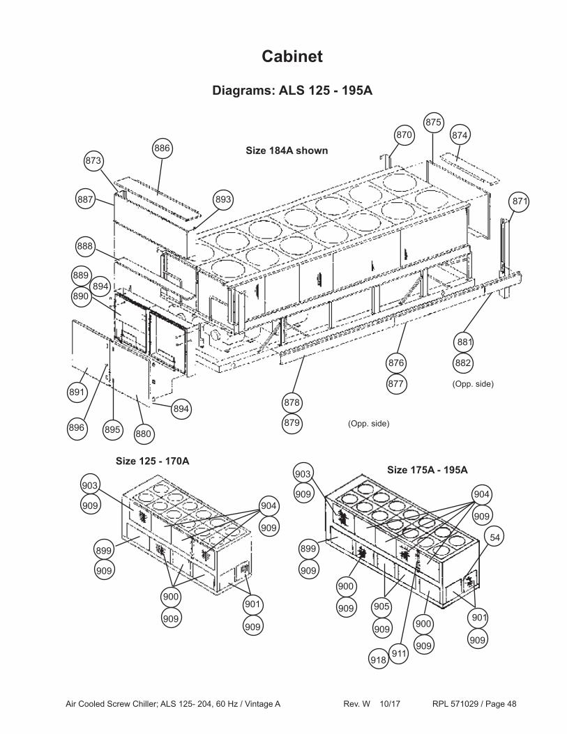
Diagrams: ALS 125 - 195A
Size 184A shown874
893
886873
887
888
870
889
895
894
880
891
890
896
871
878
876
(Opp. side)
(Opp. side)
875
882
881
877
879
Cabinet
900
899
900
901
Size 175A - 195ASize 125 - 170A
899
901
900
905
909
909909
909
909
909
909 909
909
904
903
909909
904
903
909
54
911918
894
Air Cooled Screw Chiller; ALS 125- 204, 60 Hz / Vintage A Rev. W 10/17 RPL 571029 / Page 49
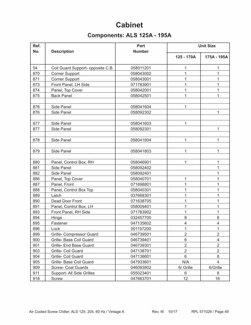
CabinetComponents: ALS 125A - 195A
Ref. Part Unit SizeNo. Description Number 125 - 170A 175A - 195A
54 Coil Guard Support- opposite C.B. 058011201 1 1870 Corner Support 058043002 1 1871 Corner Support 058043001 1 1873 Front Panel, LH Side 071783901 1 1874 Panel, Top Cover 058042001 1 1875 Back Panel 058042501 1 1
876 Side Panel 058041604 1 876 Side Panel 058092302 1
877 Side Panel 058041603 1 877 Side Panel 058092301 1
878 Side Panel 058041804 1 1
879 Side Panel 058041803 1 1
880 Panel, Control Box, RH 058046901 1 1881 Side Panel 058092402 1882 Side Panel 058092401 1886 Panel, Top Cover 058040701 1 1887 Panel, Front 071698801 1 1888 Panel, Control Box Top 058040301 1 1889 Latch 037668301 1 1890 Dead Door Front 071638705 1 1891 Panel, Control Box, LH 058009401 1 1893 Front Panel, RH Side 071783902 1 1894 Hinge 032457700 8 8895 Fastener 047135602 4 4896 Lock 001157200 1 1899 Grille- Compressor Guard 046739501 2 2900 Grille- Base Coil Guard 046739401 6 4901 Grille- End Base Guard 046739301 2 2903 Grille- Coil Guard 047138701 2 2904 Grille- Coil Guard 047138601 6 8905 Grille- Base Coil Guard 047933601 N/A 4909 Screw- Coal Guards 046093802 6/ Grille 6/Grille911 Support- All Side Grilles 055023401 6 8918 Screw 047663701 12 16
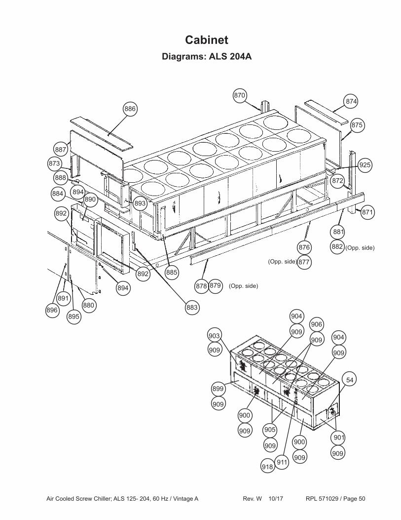
Air Cooled Screw Chiller; ALS 125- 204, 60 Hz / Vintage A Rev. W 10/17 RPL 571029 / Page 50
Cabinet
899
900
901900
905
909
909
909
909 909
903
909
909
904
909
904909
906
54
911918
886
884
891
890
878
(Opp. side)876
(Opp. side)
(Opp. side)
882
881
877
879
873
893
888
887
892
896895
880
894
892
883
885
871
872
925
874
875
870
Diagrams: ALS 204A
894
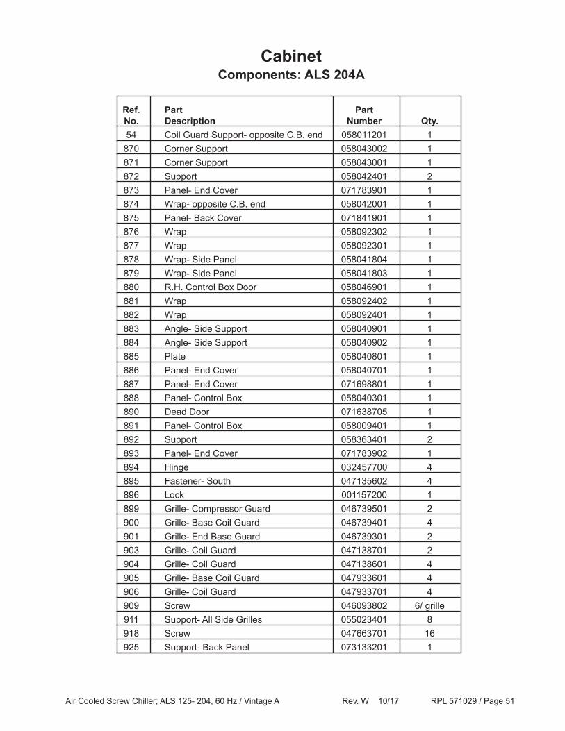
Air Cooled Screw Chiller; ALS 125- 204, 60 Hz / Vintage A Rev. W 10/17 RPL 571029 / Page 51
CabinetComponents: ALS 204A
Ref. Part Part No. Description Number Qty. 54 Coil Guard Support- opposite C.B. end 058011201 1 870 Corner Support 058043002 1 871 Corner Support 058043001 1 872 Support 058042401 2 873 Panel- End Cover 071783901 1 874 Wrap- opposite C.B. end 058042001 1 875 Panel- Back Cover 071841901 1 876 Wrap 058092302 1 877 Wrap 058092301 1 878 Wrap- Side Panel 058041804 1 879 Wrap- Side Panel 058041803 1 880 R.H. Control Box Door 058046901 1 881 Wrap 058092402 1 882 Wrap 058092401 1 883 Angle- Side Support 058040901 1 884 Angle- Side Support 058040902 1 885 Plate 058040801 1 886 Panel- End Cover 058040701 1 887 Panel- End Cover 071698801 1 888 Panel- Control Box 058040301 1 890 Dead Door 071638705 1 891 Panel- Control Box 058009401 1 892 Support 058363401 2 893 Panel- End Cover 071783902 1 894 Hinge 032457700 4 895 Fastener- South 047135602 4 896 Lock 001157200 1 899 Grille- Compressor Guard 046739501 2 900 Grille- Base Coil Guard 046739401 4 901 Grille- End Base Guard 046739301 2 903 Grille- Coil Guard 047138701 2 904 Grille- Coil Guard 047138601 4 905 Grille- Base Coil Guard 047933601 4 906 Grille- Coil Guard 047933701 4 909 Screw 046093802 6/ grille 911 Support- All Side Grilles 055023401 8 918 Screw 047663701 16 925 Support- Back Panel 073133201 1
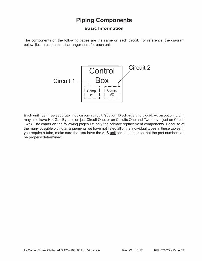
Air Cooled Screw Chiller; ALS 125- 204, 60 Hz / Vintage A Rev. W 10/17 RPL 571029 / Page 52
Piping ComponentsBasic Information
The components on the following pages are the same on each circuit. For reference, the diagram below illustrates the circuit arrangements for each unit.
Each unit has three separate lines on each circuit: Suction, Discharge and Liquid. As an option, a unit may also have Hot Gas Bypass on just Circuit One, or on Circuits One and Two (never just on Circuit Two). The charts on the following pages list only the primary replacement components. Because of the many possible piping arrangements we have not listed all of the individual tubes in these tables. If you require a tube, make sure that you have the ALS unit serial number so that the part number can be properly determined.
Control BoxCircuit 1
Circuit 2
Comp. #1
Comp. #2

Air Cooled Screw Chiller; ALS 125- 204, 60 Hz / Vintage A Rev. W 10/17 RPL 571029 / Page 53
Piping Components, ContinuedALS 125A
Quantities reflect a PER CIRCUIT number. The piping arrangements for each circuit are different, but the primary components are the same.
Discharge Line Qty Description Part Number 1 Pressure Valve 039441300
Liquid Line Qty Description Part Number 1 Sight Glass 022427700
1 Sight Glass Saddle 022431100
2 Charge Valve 038689900
4 Shrader Valve Cap 032943500
4 Shrader Valve Core 026541100
1 Shut Off Valve- 1.125" 048169601
1 Solenoid Valve- 1.375" 025327600
1 Expansion Valve w/ Motor 100Ton 072260701
Expansion Valve Motor Only 072994501
2 Flange- Expansion Valve & Evap. 070290301 (until 7/97)
074614801 (after 7/97)
2 Flange O'Ring- TXV & Evap. 735073688
1 Filter Drier Shell 019190500
2 Drier Core 070339101
2 Drier Gasket- Felt 074783601
2 Filter Drier Strap 074635201
Liquid Injection Line Qty Description Part Number 1 Solenoid Valve- .625" * 735048464
1 Sight Glass 015997804
Hot Gas Bypass Qty Description Part Number 1 Hot Gas Bypass Valve- 1.125" 019282100
1 Solenoid Valve- 1.125" 072040101
Water Piping Qty Description Part Number 1 Water Flow Switch 017503300
* Can also use part number 032189304 with Reducer part number 04116515.
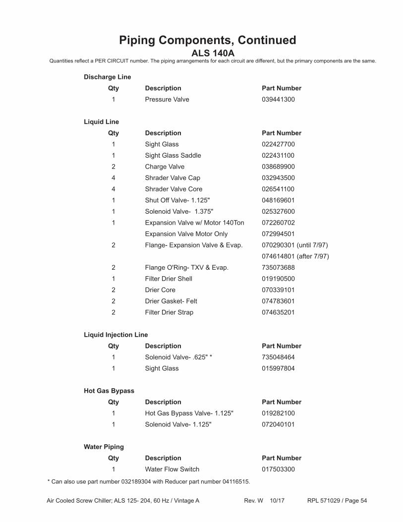
Air Cooled Screw Chiller; ALS 125- 204, 60 Hz / Vintage A Rev. W 10/17 RPL 571029 / Page 54
Piping Components, ContinuedALS 140A
Quantities reflect a PER CIRCUIT number. The piping arrangements for each circuit are different, but the primary components are the same.
Discharge Line Qty Description Part Number 1 Pressure Valve 039441300
Liquid Line Qty Description Part Number 1 Sight Glass 022427700
1 Sight Glass Saddle 022431100
2 Charge Valve 038689900
4 Shrader Valve Cap 032943500
4 Shrader Valve Core 026541100
1 Shut Off Valve- 1.125" 048169601
1 Solenoid Valve- 1.375" 025327600
1 Expansion Valve w/ Motor 140Ton 072260702
Expansion Valve Motor Only 072994501
2 Flange- Expansion Valve & Evap. 070290301 (until 7/97)
074614801 (after 7/97)
2 Flange O'Ring- TXV & Evap. 735073688
1 Filter Drier Shell 019190500
2 Drier Core 070339101
2 Drier Gasket- Felt 074783601
2 Filter Drier Strap 074635201
Liquid Injection Line Qty Description Part Number 1 Solenoid Valve- .625" * 735048464
1 Sight Glass 015997804
Hot Gas Bypass Qty Description Part Number 1 Hot Gas Bypass Valve- 1.125" 019282100
1 Solenoid Valve- 1.125" 072040101
Water Piping Qty Description Part Number 1 Water Flow Switch 017503300
* Can also use part number 032189304 with Reducer part number 04116515.

Air Cooled Screw Chiller; ALS 125- 204, 60 Hz / Vintage A Rev. W 10/17 RPL 571029 / Page 55
Piping Components, ContinuedALS 155A
Quantities reflect a PER CIRCUIT number. The piping arrangements for each circuit are different, but the primary components are the same.
Discharge Line Qty Description Part Number 1 Pressure Valve 039441300
Liquid Line Qty Description Part Number 1 Sight Glass 022427700
1 Sight Glass Saddle 022431100
2 Charge Valve 038689900
4 Shrader Valve Cap 032943500
4 Shrader Valve Core 026541100
1 Shut Off Valve- 1.125" 048169601
1 Solenoid Valve- 1.375" 025327600
1 Expansion Valve w/ Motor 140Ton 072260702
Expansion Valve Motor Only 072994501
2 Flange- Expansion Valve & Evap. 070290301 (until 7/97)
074614801 (after 7/97)
2 Flange O'Ring- TXV & Evap. 735073688
1 Filter Drier Shell 019190500
2 Drier Core 070339101
2 Drier Gasket- Felt 074783601
2 Filter Drier Strap 074635201
Liquid Injection Line Qty Description Part Number 1 Solenoid Valve- .625" * 735048464
1 Sight Glass 015997804
Hot Gas Bypass Qty Description Part Number 1 Hot Gas Bypass Valve- 1.125" 019282100
1 Solenoid Valve- 1.125" 072040101
Water Piping Qty Description Part Number 1 Water Flow Switch 017503300
* Can also use part number 032189304 with Reducer part number 04116515.

Air Cooled Screw Chiller; ALS 125- 204, 60 Hz / Vintage A Rev. W 10/17 RPL 571029 / Page 56
Piping Components, ContinuedALS 170A
Quantities reflect a PER CIRCUIT number. The piping arrangements for each circuit are different, but the primary components are the same.
Discharge Line Qty Description Part Number 1 Pressure Valve 039441300
Liquid Line Qty Description Part Number 1 Sight Glass 022427700
1 Sight Glass Saddle 070761301
2 Charge Valve 038689900
4 Shrader Valve Cap 032943500
4 Shrader Valve Core 026541100
1 Shut Off Valve- 1.125" 048169601
1 Solenoid Valve- 1.375" 735048461
1 Expansion Valve w/ Motor 170Ton 072260703
Expansion Valve Motor Only 072994501
2 Flange- Expansion Valve & Evap. 070290301 (until 7/97)
074614801 (after 7/97)
2 Flange O'Ring- TXV & Evap. 735073688
1 Filter Drier Shell 024881100
2 Drier Core 070339101
2 Drier Gasket- Felt 074783601
2 Filter Drier Strap 074635201
Liquid Injection Line Qty Description Part Number 1 Solenoid Valve- .625" * 735048464
1 Sight Glass 015997804
Hot Gas Bypass Qty Description Part Number 1 Hot Gas Bypass Valve- 1.125" 019282100
1 Solenoid Valve- 1.125" 072040101
Water Piping Qty Description Part Number 1 Water Flow Switch 017503300
* Can also use part number 032189304 with Reducer part number 04116515.

Air Cooled Screw Chiller; ALS 125- 204, 60 Hz / Vintage A Rev. W 10/17 RPL 571029 / Page 57
Piping Components, ContinuedALS 175A
Quantities reflect a PER CIRCUIT number. The piping arrangements for each circuit are different, but the primary components are the same.
Discharge Line Qty Description Part Number 1 Pressure Valve 039441300
Liquid Line Qty Description Part Number 1 Sight Glass 022427700
1 Sight Glass Saddle 070761301
2 Charge Valve 038689900
4 Shrader Valve Cap 032943500
4 Shrader Valve Core 026541100
1 Shut Off Valve- 1.125" 048169601
1 Solenoid Valve- 1.375" 735048461
1 Expansion Valve w/ Motor 170Ton 072260703
Expansion Valve Motor Only 072994501
2 Flange- Expansion Valve & Evap. 070290301 (until 7/97)
074614801 (after 7/97)
2 Flange O'Ring- TXV & Evap. 735073688
1 Filter Drier Shell 024881100
2 Drier Core 070339101
2 Drier Gasket- Felt 074783601
2 Filter Drier Strap 074635201
Liquid Injection Line Qty Description Part Number 1 Solenoid Valve- .625" * 735048464
1 Sight Glass 015997804
Hot Gas Bypass Qty Description Part Number 1 Hot Gas Bypass Valve- 1.125" 019282100
1 Solenoid Valve- 1.125" 072040101
Water Piping Qty Description Part Number 1 Water Flow Switch 017503300
* Can also use part number 032189304 with Reducer part number 04116515.

Air Cooled Screw Chiller; ALS 125- 204, 60 Hz / Vintage A Rev. W 10/17 RPL 571029 / Page 58
Piping Components, ContinuedALS 185A
Quantities reflect a PER CIRCUIT number. The piping arrangements for each circuit are different, but the primary components are the same.
Discharge Line Qty Description Part Number 1 Pressure Valve 039441300
Liquid Line Qty Description Part Number 1 Sight Glass 022427700
1 Sight Glass Saddle 070761301
2 Charge Valve 038689900
4 Shrader Valve Cap 032943500
4 Shrader Valve Core 026541100
1 Shut Off Valve- 1.125" 048169601
1 Solenoid Valve- 1.375" 735048461
1 Expansion Valve w/ Motor 170Ton 072260703
Expansion Valve Motor Only 072994501
2 Flange- Expansion Valve & Evap. 070290301 (until 7/97)
074614801 (after 7/97)
2 Flange O'Ring- TXV & Evap. 735073688
1 Filter Drier Shell 024881100
2 Drier Core 070339101
2 Drier Gasket- Felt 074783601
2 Filter Drier Strap 074635201
Liquid Injection Line Qty Description Part Number 1 Solenoid Valve- .625" * 735048464
1 Sight Glass 015997804
Hot Gas Bypass Qty Description Part Number 1 Hot Gas Bypass Valve- 1.125" 019282100
1 Solenoid Valve- 1.125" 072040101
Water Piping Qty Description Part Number 1 Water Flow Switch 017503300
* Can also use part number 032189304 with Reducer part number 04116515.
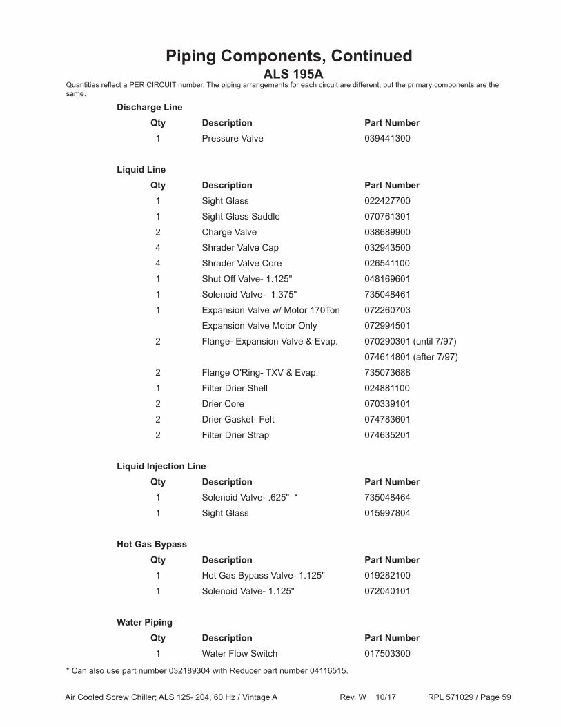
Air Cooled Screw Chiller; ALS 125- 204, 60 Hz / Vintage A Rev. W 10/17 RPL 571029 / Page 59
Piping Components, ContinuedALS 195A
Quantities reflect a PER CIRCUIT number. The piping arrangements for each circuit are different, but the primary components are the same.
Discharge Line Qty Description Part Number 1 Pressure Valve 039441300
Liquid Line Qty Description Part Number 1 Sight Glass 022427700
1 Sight Glass Saddle 070761301
2 Charge Valve 038689900
4 Shrader Valve Cap 032943500
4 Shrader Valve Core 026541100
1 Shut Off Valve- 1.125" 048169601
1 Solenoid Valve- 1.375" 735048461
1 Expansion Valve w/ Motor 170Ton 072260703
Expansion Valve Motor Only 072994501
2 Flange- Expansion Valve & Evap. 070290301 (until 7/97)
074614801 (after 7/97)
2 Flange O'Ring- TXV & Evap. 735073688
1 Filter Drier Shell 024881100
2 Drier Core 070339101
2 Drier Gasket- Felt 074783601
2 Filter Drier Strap 074635201
Liquid Injection Line Qty Description Part Number 1 Solenoid Valve- .625" * 735048464
1 Sight Glass 015997804
Hot Gas Bypass Qty Description Part Number 1 Hot Gas Bypass Valve- 1.125" 019282100
1 Solenoid Valve- 1.125" 072040101
Water Piping Qty Description Part Number 1 Water Flow Switch 017503300
* Can also use part number 032189304 with Reducer part number 04116515.
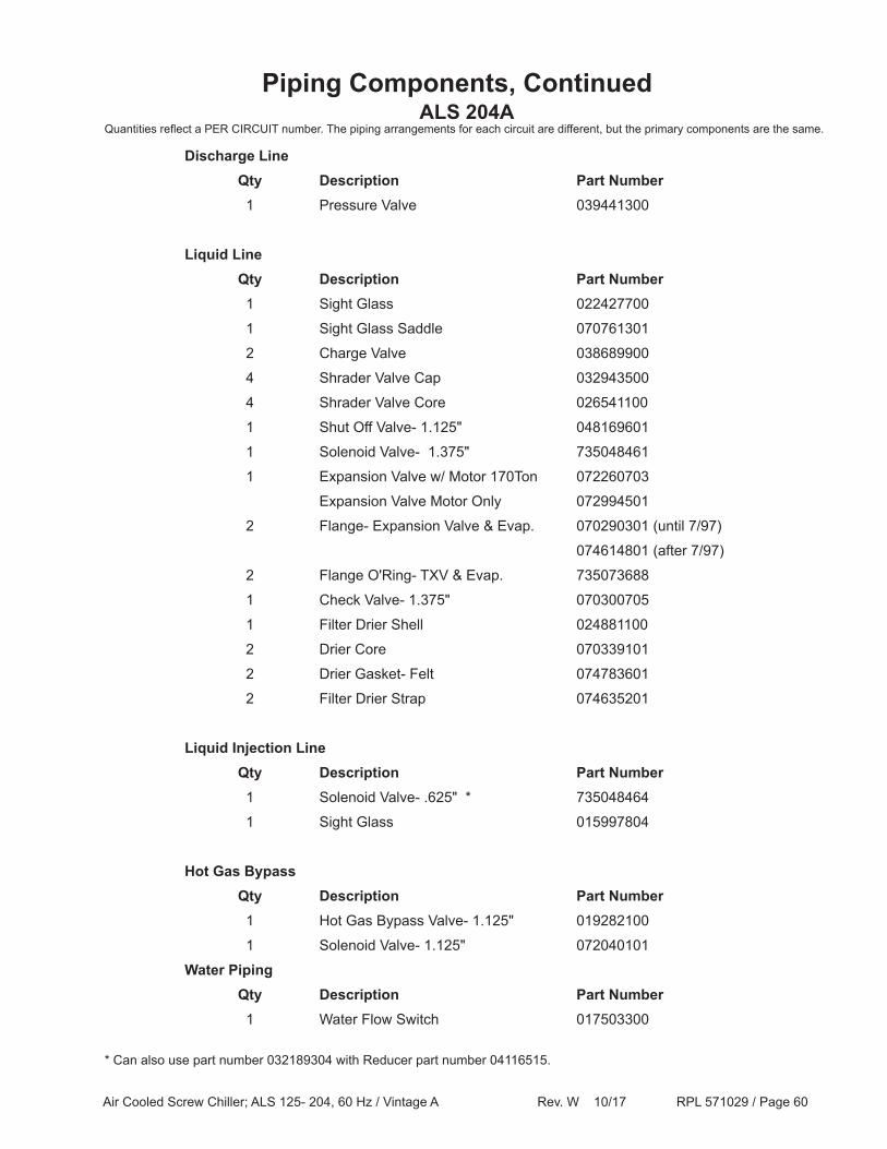
Air Cooled Screw Chiller; ALS 125- 204, 60 Hz / Vintage A Rev. W 10/17 RPL 571029 / Page 60
Piping Components, ContinuedALS 204A
Quantities reflect a PER CIRCUIT number. The piping arrangements for each circuit are different, but the primary components are the same.
Discharge Line Qty Description Part Number 1 Pressure Valve 039441300
Liquid Line Qty Description Part Number 1 Sight Glass 022427700
1 Sight Glass Saddle 070761301
2 Charge Valve 038689900
4 Shrader Valve Cap 032943500
4 Shrader Valve Core 026541100
1 Shut Off Valve- 1.125" 048169601
1 Solenoid Valve- 1.375" 735048461
1 Expansion Valve w/ Motor 170Ton 072260703
Expansion Valve Motor Only 072994501
2 Flange- Expansion Valve & Evap. 070290301 (until 7/97)
074614801 (after 7/97)
2 Flange O'Ring- TXV & Evap. 735073688
1 Check Valve- 1.375" 070300705
1 Filter Drier Shell 024881100
2 Drier Core 070339101
2 Drier Gasket- Felt 074783601
2 Filter Drier Strap 074635201
Liquid Injection Line Qty Description Part Number 1 Solenoid Valve- .625" * 735048464
1 Sight Glass 015997804
Hot Gas Bypass Qty Description Part Number 1 Hot Gas Bypass Valve- 1.125" 019282100
1 Solenoid Valve- 1.125" 072040101
Water Piping Qty Description Part Number 1 Water Flow Switch 017503300
* Can also use part number 032189304 with Reducer part number 04116515.
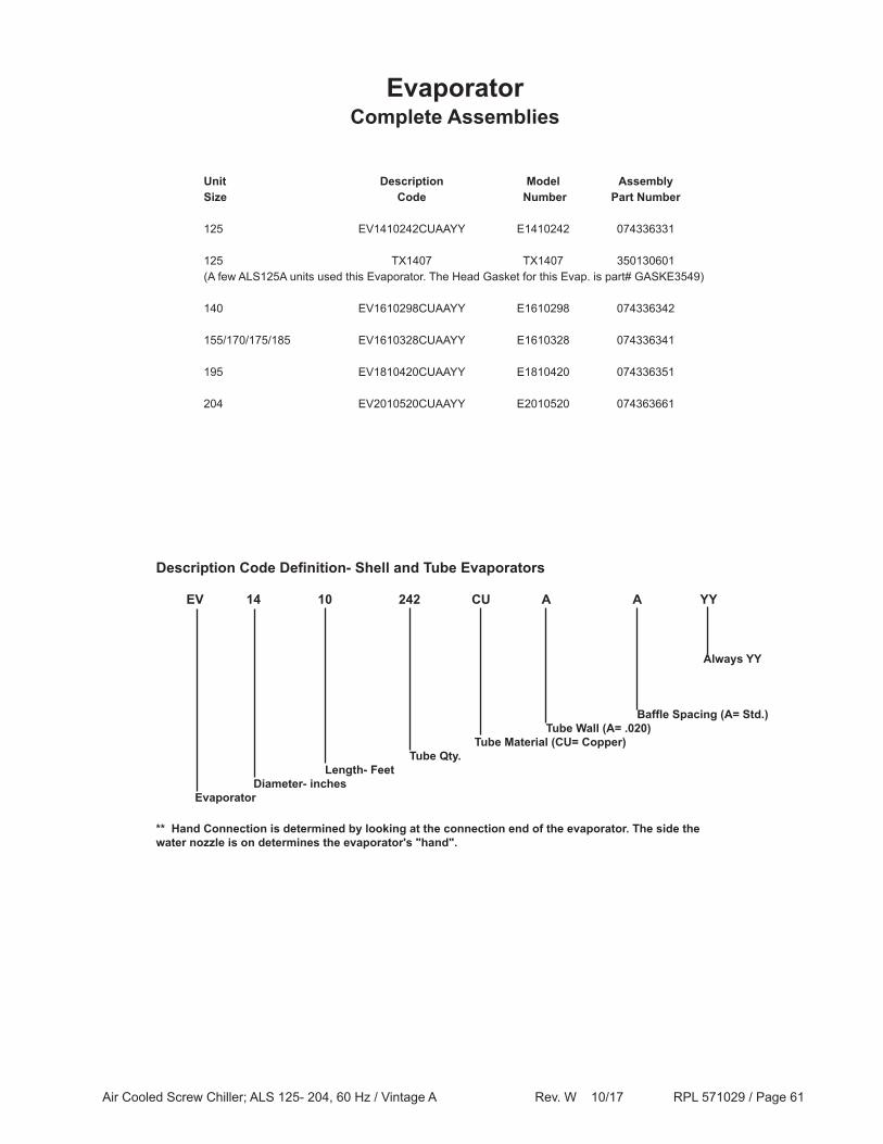
Air Cooled Screw Chiller; ALS 125- 204, 60 Hz / Vintage A Rev. W 10/17 RPL 571029 / Page 61
EvaporatorComplete Assemblies
Unit Description Model AssemblySize Code Number Part Number 125 EV1410242CUAAYY E1410242 074336331
125 TX1407 TX1407 350130601(A few ALS125A units used this Evaporator. The Head Gasket for this Evap. is part# GASKE3549)
140 EV1610298CUAAYY E1610298 074336342
155/170/175/185 EV1610328CUAAYY E1610328 074336341
195 EV1810420CUAAYY E1810420 074336351
204 EV2010520CUAAYY E2010520 074363661
Description Code Definition- Shell and Tube Evaporators
EV 14 10 242 CU A A YY
Always YY
Baffle Spacing (A= Std.) Tube Wall (A= .020) Tube Material (CU= Copper) Tube Qty. Length- Feet Diameter- inches Evaporator
** Hand Connection is determined by looking at the connection end of the evaporator. The side the water nozzle is on determines the evaporator's "hand".
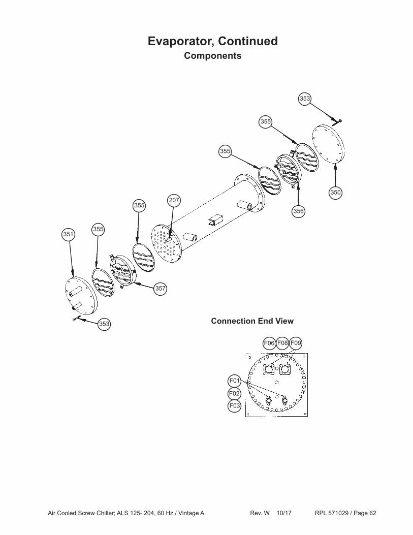
Air Cooled Screw Chiller; ALS 125- 204, 60 Hz / Vintage A Rev. W 10/17 RPL 571029 / Page 62
Evaporator, ContinuedComponents
353
355
355
350
356
207355
355351
353
357
Connection End View
F01
F02
F03
F08F06 F09
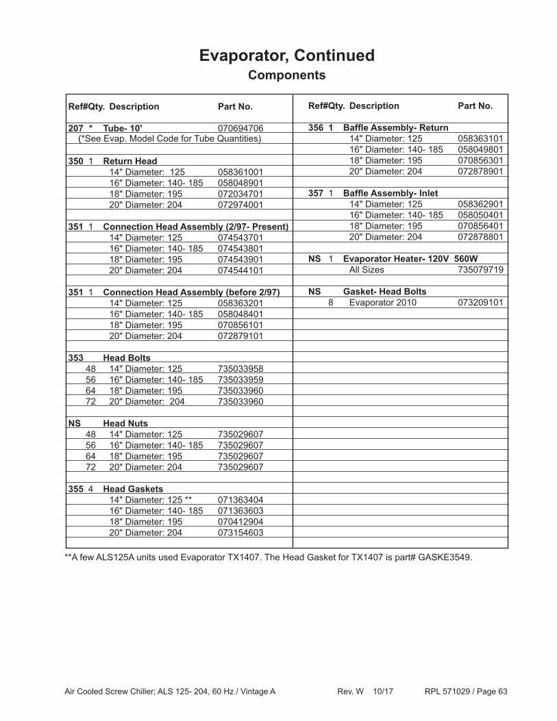
Air Cooled Screw Chiller; ALS 125- 204, 60 Hz / Vintage A Rev. W 10/17 RPL 571029 / Page 63
(*See Evap. Model Code for Tube Quantities)
Ref# Qty. Description Part No.
207 * Tube- 10' 070694706
350 1 Return Head 14" Diameter: 125 058361001 16" Diameter: 140- 185 058048901 18" Diameter: 195 072034701 20" Diameter: 204 072974001
351 1 Connection Head Assembly (2/97- Present) 14" Diameter: 125 074543701 16" Diameter: 140- 185 074543801 18" Diameter: 195 074543901 20" Diameter: 204 074544101
351 1 Connection Head Assembly (before 2/97) 14" Diameter: 125 058363201 16" Diameter: 140- 185 058048401 18" Diameter: 195 070856101 20" Diameter: 204 072879101
353 Head Bolts 48 14" Diameter: 125 735033958 56 16" Diameter: 140- 185 735033959 64 18" Diameter: 195 735033960 72 20" Diameter: 204 735033960
NS Head Nuts 48 14" Diameter: 125 735029607 56 16" Diameter: 140- 185 735029607 64 18" Diameter: 195 735029607 72 20" Diameter: 204 735029607
355 4 Head Gaskets 14" Diameter: 125 ** 071363404 16" Diameter: 140- 185 071363603 18" Diameter: 195 070412904 20" Diameter: 204 073154603
Evaporator, ContinuedComponents
Ref# Qty. Description Part No.
356 1 Baffle Assembly- Return 14" Diameter: 125 058363101 16" Diameter: 140- 185 058049801 18" Diameter: 195 070856301 20" Diameter: 204 072878901
357 1 Baffle Assembly- Inlet 14" Diameter: 125 058362901 16" Diameter: 140- 185 058050401 18" Diameter: 195 070856401 20" Diameter: 204 072878801
NS 1 Evaporator Heater- 120V 560W All Sizes 735079719
NS Gasket- Head Bolts 8 Evaporator 2010 073209101
**A few ALS125A units used Evaporator TX1407. The Head Gasket for TX1407 is part# GASKE3549.
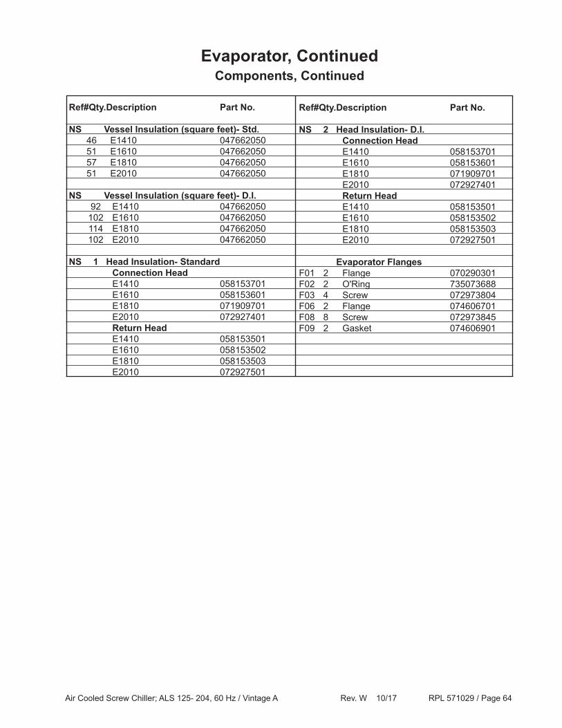
Air Cooled Screw Chiller; ALS 125- 204, 60 Hz / Vintage A Rev. W 10/17 RPL 571029 / Page 64
Ref# Qty. Description Part No. NS Vessel Insulation (square feet)- Std. 46 E1410 047662050 51 E1610 047662050 57 E1810 047662050 51 E2010 047662050
NS Vessel Insulation (square feet)- D.I. 92 E1410 047662050 102 E1610 047662050 114 E1810 047662050 102 E2010 047662050
NS 1 Head Insulation- Standard Connection Head E1410 058153701 E1610 058153601 E1810 071909701 E2010 072927401 Return Head E1410 058153501 E1610 058153502 E1810 058153503 E2010 072927501
Evaporator, ContinuedComponents, Continued
Ref# Qty. Description Part No. NS 2 Head Insulation- D.I. Connection Head E1410 058153701 E1610 058153601 E1810 071909701 E2010 072927401 Return Head E1410 058153501 E1610 058153502 E1810 058153503 E2010 072927501
Evaporator FlangesF01 2 Flange 070290301F02 2 O'Ring 735073688F03 4 Screw 072973804F06 2 Flange 074606701F08 8 Screw 072973845F09 2 Gasket 074606901
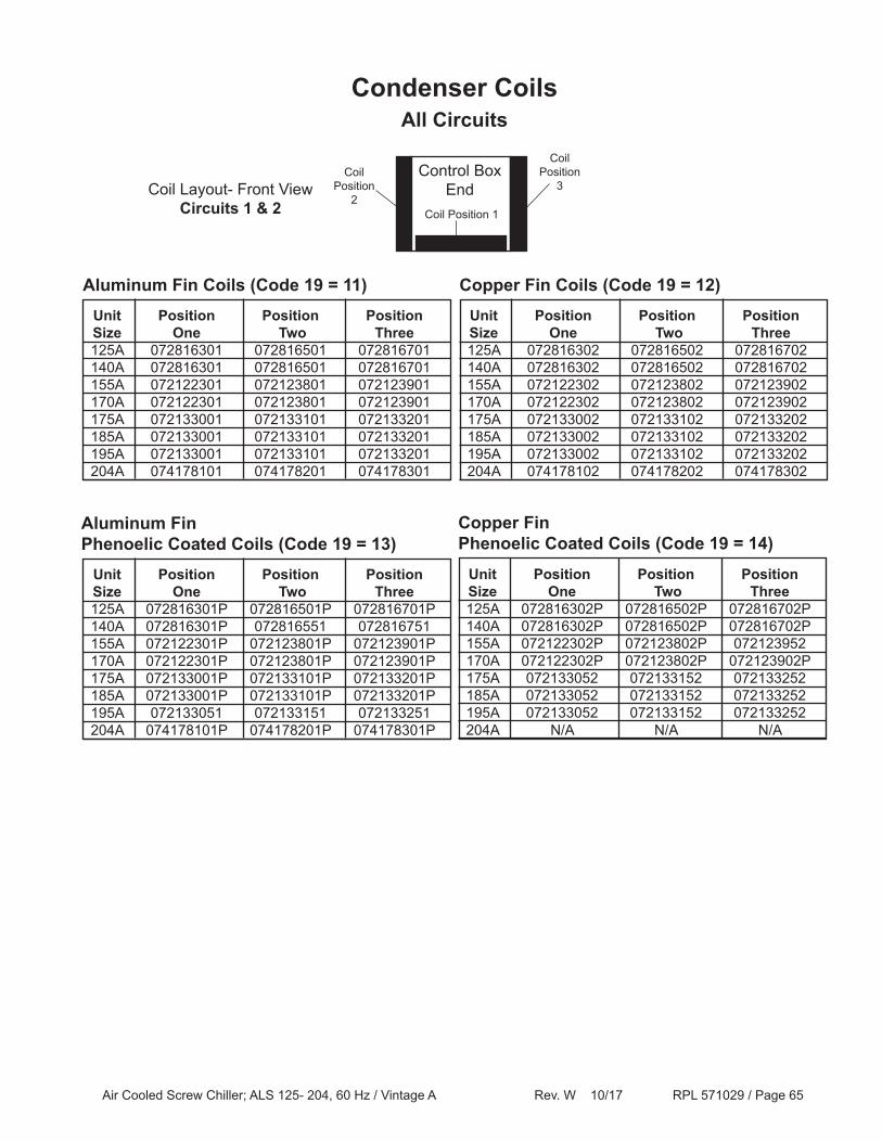
Air Cooled Screw Chiller; ALS 125- 204, 60 Hz / Vintage A Rev. W 10/17 RPL 571029 / Page 65
Unit Position Position Position Size One Two Three 125A 072816301 072816501 072816701 140A 072816301 072816501 072816701 155A 072122301 072123801 072123901 170A 072122301 072123801 072123901 175A 072133001 072133101 072133201 185A 072133001 072133101 072133201 195A 072133001 072133101 072133201 204A 074178101 074178201 074178301
Condenser CoilsAll Circuits
Coil Layout- Front ViewCircuits 1 & 2
Aluminum Fin Coils (Code 19 = 11) Unit Position Position Position Size One Two Three 125A 072816302 072816502 072816702 140A 072816302 072816502 072816702 155A 072122302 072123802 072123902 170A 072122302 072123802 072123902 175A 072133002 072133102 072133202 185A 072133002 072133102 072133202 195A 072133002 072133102 072133202 204A 074178102 074178202 074178302
Copper Fin Coils (Code 19 = 12)
Unit Position Position Position Size One Two Three 125A 072816301P 072816501P 072816701P 140A 072816301P 072816551 072816751 155A 072122301P 072123801P 072123901P 170A 072122301P 072123801P 072123901P 175A 072133001P 072133101P 072133201P 185A 072133001P 072133101P 072133201P 195A 072133051 072133151 072133251 204A 074178101P 074178201P 074178301P
Aluminum Fin Phenoelic Coated Coils (Code 19 = 13)
Unit Position Position Position Size One Two Three 125A 072816302P 072816502P 072816702P 140A 072816302P 072816502P 072816702P 155A 072122302P 072123802P 072123952 170A 072122302P 072123802P 072123902P 175A 072133052 072133152 072133252 185A 072133052 072133152 072133252 195A 072133052 072133152 072133252 204A N/A N/A N/A
Copper Fin Phenoelic Coated Coils (Code 19 = 14)
CoilPosition
2
Control BoxEnd
CoilPosition
3
Coil Position 1
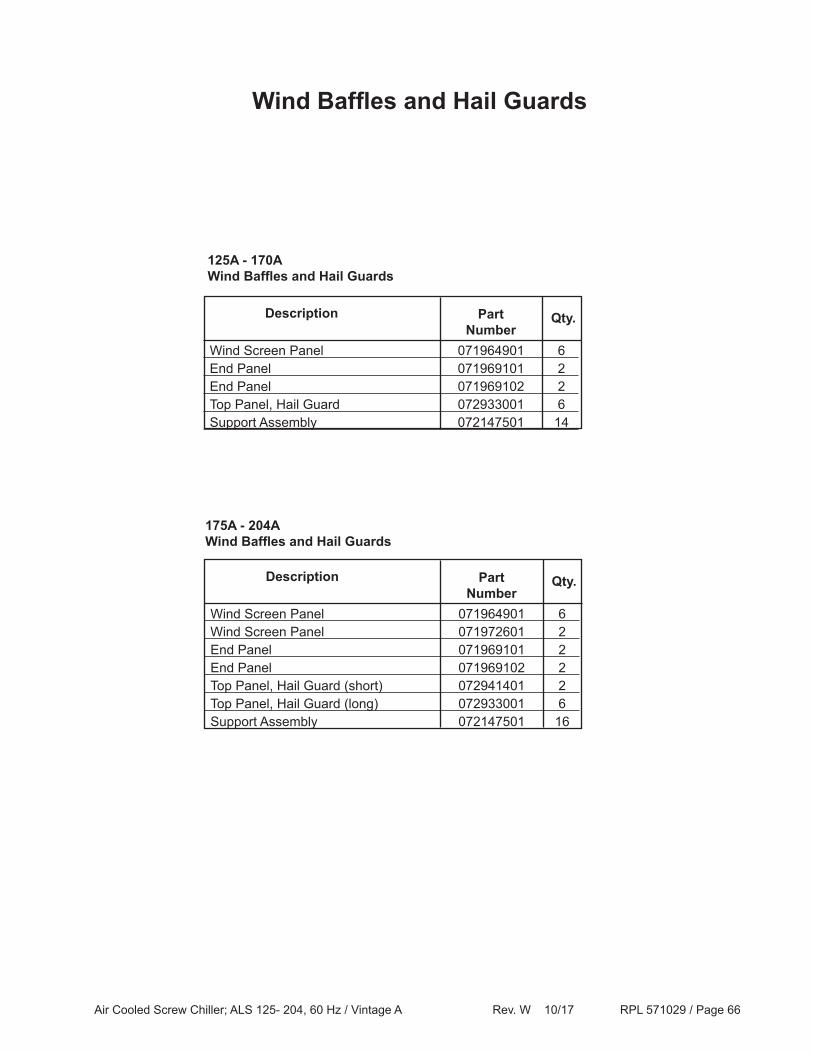
Air Cooled Screw Chiller; ALS 125- 204, 60 Hz / Vintage A Rev. W 10/17 RPL 571029 / Page 66
Wind Baffles and Hail Guards
125A - 170AWind Baffles and Hail Guards
Wind Screen Panel 071964901 6 Wind Screen Panel 071972601 2 End Panel 071969101 2 End Panel 071969102 2 Top Panel, Hail Guard (short) 072941401 2 Top Panel, Hail Guard (long) 072933001 6 Support Assembly 072147501 16
PartNumber
Description
175A - 204AWind Baffles and Hail Guards
Qty.
Wind Screen Panel 071964901 6 End Panel 071969101 2 End Panel 071969102 2 Top Panel, Hail Guard 072933001 6 Support Assembly 072147501 14
PartNumber
Description
Qty.