Embed Size (px)
Citation preview

© 2008 Microchip Technology Inc. DS51738B
MCP6V01Thermocouple Auto-Zeroed
Reference Design

Note the following details of the code protection feature on Microchip devices:• Microchip products meet the specification contained in their particular Microchip Data Sheet.
• Microchip believes that its family of products is one of the most secure families of its kind on the market today, when used in the intended manner and under normal conditions.
• There are dishonest and possibly illegal methods used to breach the code protection feature. All of these methods, to our knowledge, require using the Microchip products in a manner outside the operating specifications contained in Microchip’s Data Sheets. Most likely, the person doing so is engaged in theft of intellectual property.
• Microchip is willing to work with the customer who is concerned about the integrity of their code.
• Neither Microchip nor any other semiconductor manufacturer can guarantee the security of their code. Code protection does not mean that we are guaranteeing the product as “unbreakable.”
Code protection is constantly evolving. We at Microchip are committed to continuously improving the code protection features of ourproducts. Attempts to break Microchip’s code protection feature may be a violation of the Digital Millennium Copyright Act. If such actsallow unauthorized access to your software or other copyrighted work, you may have a right to sue for relief under that Act.
Information contained in this publication regarding deviceapplications and the like is provided only for your convenienceand may be superseded by updates. It is your responsibility toensure that your application meets with your specifications.MICROCHIP MAKES NO REPRESENTATIONS ORWARRANTIES OF ANY KIND WHETHER EXPRESS ORIMPLIED, WRITTEN OR ORAL, STATUTORY OROTHERWISE, RELATED TO THE INFORMATION,INCLUDING BUT NOT LIMITED TO ITS CONDITION,QUALITY, PERFORMANCE, MERCHANTABILITY ORFITNESS FOR PURPOSE. Microchip disclaims all liabilityarising from this information and its use. Use of Microchipdevices in life support and/or safety applications is entirely atthe buyer’s risk, and the buyer agrees to defend, indemnify andhold harmless Microchip from any and all damages, claims,suits, or expenses resulting from such use. No licenses areconveyed, implicitly or otherwise, under any Microchipintellectual property rights.
DS51738B-page ii
Trademarks
The Microchip name and logo, the Microchip logo, Accuron, dsPIC, KEELOQ, KEELOQ logo, MPLAB, PIC, PICmicro, PICSTART, rfPIC, SmartShunt and UNI/O are registered trademarks of Microchip Technology Incorporated in the U.S.A. and other countries.
FilterLab, Linear Active Thermistor, MXDEV, MXLAB, SEEVAL, SmartSensor and The Embedded Control Solutions Company are registered trademarks of Microchip Technology Incorporated in the U.S.A.
Analog-for-the-Digital Age, Application Maestro, CodeGuard, dsPICDEM, dsPICDEM.net, dsPICworks, dsSPEAK, ECAN, ECONOMONITOR, FanSense, In-Circuit Serial Programming, ICSP, ICEPIC, Mindi, MiWi, MPASM, MPLAB Certified logo, MPLIB, MPLINK, mTouch, PICkit, PICDEM, PICDEM.net, PICtail, PIC32 logo, PowerCal, PowerInfo, PowerMate, PowerTool, REAL ICE, rfLAB, Select Mode, Total Endurance, WiperLock and ZENA are trademarks of Microchip Technology Incorporated in the U.S.A. and other countries.
SQTP is a service mark of Microchip Technology Incorporated in the U.S.A.
All other trademarks mentioned herein are property of their respective companies.
© 2008, Microchip Technology Incorporated, Printed in the U.S.A., All Rights Reserved.
Printed on recycled paper.
© 2008 Microchip Technology Inc.
Microchip received ISO/TS-16949:2002 certification for its worldwide headquarters, design and wafer fabrication facilities in Chandler and Tempe, Arizona; Gresham, Oregon and design centers in California and India. The Company’s quality system processes and procedures are for its PIC® MCUs and dsPIC® DSCs, KEELOQ® code hopping devices, Serial EEPROMs, microperipherals, nonvolatile memory and analog products. In addition, Microchip’s quality system for the design and manufacture of development systems is ISO 9001:2000 certified.

MCP6V01 THERMOCOUPLEAUTO-ZEROED REFERENCE DESIGN
Table of Contents
Preface ........................................................................................................................... 1Introduction............................................................................................................ 1Document Layout .................................................................................................. 1Conventions Used in this Guide ............................................................................ 2Recommended Reading........................................................................................ 3The Microchip Web Site ........................................................................................ 3Customer Support ................................................................................................. 4Document Revision History ................................................................................... 4
Chapter 1. Product Overview1.1 Introduction ..................................................................................................... 51.2 MCP6V01 Thermocouple Auto-Zeroed Reference Design Kit Contents ........ 51.3 MCP6V01 Thermocouple Auto-Zeroed Reference Design Description ......... 6
Chapter 2. Installation and Operation2.1 Introduction ................................................................................................... 112.2 Required Tool ............................................................................................... 112.3 MCP6V01 Thermocouple Auto-Zeroed Reference Design Setup ................ 112.4 MCP6V01 Thermocouple Auto-Zeroed Reference Design Operation ......... 12
Appendix A. Schematic and LayoutA.1 Introduction .................................................................................................. 17A.2 Board - Schematic ....................................................................................... 18A.3 Board - Top Silk Layer ................................................................................. 19A.4 Board - Top Metal Layer .............................................................................. 19A.5 Board - Metal Layer 2 .................................................................................. 20A.6 Board - Metal Layer 3 .................................................................................. 20A.7 Board - Bottom Silk Layer (Bottom View) .................................................... 21A.8 Board - Bottom Layer ................................................................................... 21
Appendix B. Bill Of Materials (BOM)Worldwide Sales and Service .................................................................................... 26
© 2008 Microchip Technology Inc. DS51738B-page iii

MCP6V01 Thermocouple Auto-Zeroed Reference Design
NOTES:
DS51738B-page iv © 2008 Microchip Technology Inc.

MCP6V01 THERMOCOUPLEAUTO-ZEROED REFERENCE DESIGN
Preface
INTRODUCTIONThis chapter contains general information that will be useful to know before using the MCP6V01 Thermocouple Auto-Zeroed Reference Design. Items discussed in this chapter include:• Document Layout• Conventions Used in this Guide• Recommended Reading• The Microchip Web Site• Customer Support• Document Revision History
DOCUMENT LAYOUTThis document describes how to use the MCP6V01 Thermocouple Auto-Zeroed Reference Design as a development tool to emulate and debug firmware on a target board. The manual layout is as follows:• Chapter 1. “Product Overview” - Provides the important information about the
MCP6V01 Thermocouple Auto-Zeroed Reference Design.• Chapter 2. “Installation and Operation” – Covers the installation and operation
of the MCP6V01 Thermocouple Auto-Zeroed Reference Design. It shows how to set up the board, and demonstrates how to verify the operation.
• Appendix A. “Schematic and Layout” – Shows the schematic and board layouts for the MCP6V01 Thermocouple Auto-Zeroed Reference Design.
• Appendix B. “Bill Of Materials (BOM)” – Lists the parts used to build the MCP6V01 Thermocouple Auto-Zeroed Reference Design.
NOTICE TO CUSTOMERS
All documentation becomes dated, and this manual is no exception. Microchip tools and documentation are constantly evolving to meet customer needs, so some actual dialogs and/or tool descriptions may differ from those in this document. Please refer to our web site (www.microchip.com) to obtain the latest documentation available.
Documents are identified with a “DS” number. This number is located on the bottom of each page, in front of the page number. The numbering convention for the DS number is “DSXXXXXA”, where “XXXXX” is the document number and “A” is the revision level of the document.
For the most up-to-date information on development tools, see the MPLAB® IDE on-line help. Select the Help menu, and then Topics to open a list of available on-line help files.
© 2008 Microchip Technology Inc. DS51738B- page 1

MCP6V01 Thermocouple Auto-Zeroed Reference Design
CONVENTIONS USED IN THIS GUIDEThis manual uses the following documentation conventions:
DOCUMENTATION CONVENTIONSDescription Represents Examples
Arial font:Italic characters Referenced books MPLAB® IDE User’s Guide
Emphasized text ...is the only compiler...Initial caps A window the Output window
A dialog the Settings dialogA menu selection select Enable Programmer
Quotes A field name in a window or dialog
“Save project before build”
Underlined, italic text with right angle bracket
A menu path File>Save
Bold characters A dialog button Click OKA tab Click the Power tab
N‘Rnnnn A number in verilog format, where N is the total number of digits, R is the radix and n is a digit.
4‘b0010, 2‘hF1
Text in angle brackets < > A key on the keyboard Press <Enter>, <F1>Courier New font:Plain Courier New Sample source code #define START
Filenames autoexec.batFile paths c:\mcc18\h
Keywords _asm, _endasm, static
Command-line options -Opa+, -Opa-Bit values 0, 1
Constants 0xFF, ‘A’
Italic Courier New A variable argument file.o, where file can be any valid filename
Square brackets [ ] Optional arguments mcc18 [options] file [options]
Curly brackets and pipe character: { | }
Choice of mutually exclusive arguments; an OR selection
errorlevel {0|1}
Ellipses... Replaces repeated text var_name [, var_name...]
Represents code supplied by user
void main (void){ ...}
DS51738B- page 2 © 2008 Microchip Technology Inc.

Preface
RECOMMENDED READINGThis user's guide describes how to use MCP6V01 Thermocouple Auto-Zeroed Reference Design. Other useful documents are listed below. The following Microchip documents are available and recommended as supplemental reference resources.MCP6V01/2/3/6/7/8 Data Sheet, “Auto-Zeroed Op Amps” (DS51738)This data sheet provides detailed information regarding the MCP6V0X Op Amps.MCP6001/2/4 Data Sheet, “1 MHz, Low-Power Op Amps” (DS21733)This data sheet provides detailed information regarding the MCP600X Op Amps.MCP1525/41 Data Sheet, “2.5V and 4.096V Voltage References” (DS21653)This data sheet provides detailed information on the MCP15XX Voltage References.MCP9800/1/2/3 Data Sheet, “2-Wire High-Accuracy Temperature Sensor” (DS21909)This data sheet provides detailed information regarding the MCP980X Temperature Sensors.PIC18F2455/2550/4455/4550 Data Sheet, “28/40/44-Pin, High-Performance, Enhanced Flash, USB Microcontrollers with nanoWatt Technology“ (DS39632)This data sheet provides detailed information regarding the PIC18F2455/2550/4455/4550 Microcontrollers.AN679, “Temperature Sensing Technologies” (DS00679)This application note covers the most popular temperature sensor technologies and helps determine the most appropriate sensor for an application.AN684, “Single Supply Temperature Sensing with Thermocouples” (DS00684)This application note focuses on thermocouple circuit solutions. It builds from signal conditioning components to complete application circuits.AN699, “Anti-Aliasing, Analog Filters for Data Acquisition Systems” (DS00699)A tutorial on active analog filters and their most common applications.“Signal Chain Design Guide” (DS21825)
THE MICROCHIP WEB SITEMicrochip provides online support via our web site at www.microchip.com. This web site is used as a means to make files and information easily available to customers. Accessible by using your favorite Internet browser, the web site contains the following information:• Product Support – Data sheets and errata, application notes and sample
programs, design resources, user’s guides and hardware support documents, latest software releases and archived software
• General Technical Support – Frequently Asked Questions (FAQs), technical support requests, online discussion groups, Microchip consultant program member listing
• Business of Microchip – Product selector and ordering guides, latest Microchip press releases, listing of seminars and events, listings of Microchip sales offices, distributors and factory representatives
© 2008 Microchip Technology Inc. DS51738B- page 3

MCP6V01 Thermocouple Auto-Zeroed Reference Design
CUSTOMER SUPPORTUsers of Microchip products can receive assistance through several channels:• Distributor or Representative• Local Sales Office• Field Application Engineer (FAE)• Technical SupportCustomers should contact their distributor, representative or field application engineer (FAE) for support. Local sales offices are also available to help customers. A listing of sales offices and locations is included in the back of this document.Technical support is available through the web site at: http://support.microchip.com
DOCUMENT REVISION HISTORY
Revision B (December 2008)• Updated the Bottom Metal Layer print.• Updated Product Review.
Revision A (May 2008)• Initial Release of this Document.
DS51738B- page 4 © 2008 Microchip Technology Inc.

MCP6V01 THERMOCOUPLEAUTO-ZEROED REFERENCE DESIGN
Chapter 1. Product Overview
1.1 INTRODUCTIONThe MCP6V01 Thermocouple Auto-Zeroed Reference Design is described by the following:• Assembly # : 114-00169• Order # : MCP6V01RD-TCPL• Name: MCP6V01 Thermocouple Auto-Zeroed Reference Design Board Items discussed in this chapter include:• MCP6V01 Thermocouple Auto-Zeroed Reference Design Board Kit Contents• MCP6V01 Thermocouple Auto-Zeroed Reference Design Board Description• Associated Tools
1.2 MCP6V01 THERMOCOUPLE AUTO-ZEROED REFERENCE DESIGN KIT CONTENTS
• MCP6V01 Thermocouple Auto-Zeroed Reference Design (102-00169)• Important “Read First” Information• Accessory Bag - Contains a K-type thermocouple and an USB cable• Analog and Interface Products Demonstration Boards CD-ROM (DS21912)
includes:- MCP6V01 Thermocouple Auto-Zeroed Reference Design (D51738)- Thermal Management Software- Firmware for PIC18F2550
FIGURE 1-1: MCP6V01 Thermocouple Auto-Zeroed Reference Design Kit.
© 2008 Microchip Technology Inc. DS51738B- page 5

MCP6V01 Thermocouple Auto-Zeroed Reference Design
1.3 MCP6V01 THERMOCOUPLE AUTO-ZEROED REFERENCE DESIGN DESCRIPTION
1.3.1 Function Block Diagram DescriptionThe MCP6V01 Thermocouple Auto-Zeroed Reference Design demonstrates how to measure electromotive force (EMF) voltage at the cold junction of the thermocouple in order to accurately measure temperature at the hot junction. This can be done by using the MCP6V01 auto-zeroed op amp because of its ultra low offset voltage (VOS) and high common mode rejection ratio (CMRR).• The difference amplifier is implemented using the MCP6V01 and 0.1% tolerance
resistors. It amplifies the EMF voltage at the cold junction of the thermocouple.• The MCP9800 senses temperature at the type K thermocouple’s connector. It
should be located as close as possible to the connector on the PCB. This measurement is used to perform cold junction compensation for the thermocouple measurement.
• The MCP1541 provides a VREF (4.1V) to the internal 10-Bit ADC of the PIC18F2550 and sets the reference voltage for the difference amplifier.
• The CVREF is the internal comparator voltage reference of PIC18F2550, which is a 16-tap resistor ladder network that provides a selectable reference voltage. The MCP6001 buffer amplifier eliminates the voltage reference output impedance problem and produces the voltage VSHIFT.
• The 2nd order RC low-pass filter that is implemented in this circuit can remove the high frequency noise and aliasing at the ADC input. The ADC of PIC18F2550 completes the analog-to-digital conversion. The data will be transferred to the PC using the USB interface.
• The Thermal Management Software on PC is used to perform data display to show the real-time temperature and apply cold junction compensation and data linearization to determine the actual temperature of the thermocouple’s hot junction (weld bead).
DS51738B- page 6 © 2008 Microchip Technology Inc.

Product Overview
Figure 1-2 shows the function block diagram of the MCP6V01 Thermocouple Auto-Zeroed Reference Design.
FIGURE 1-2: Function Block Diagram of the MCP6V01 Thermocouple Auto-Zeroed Reference Design.
Cold Junction
PIC18F2550 (USB) Microcontroller
Type K Thermocouple
PC
Compensation MCP9800
3
+
-
2nd Order RC
10-Bit ADC Module
MCP1541 4.1VVoltage Reference
Connector Temp. Sensor
Low-Pass Filter
Welded Bead
(Thermal Management Software)
USB
I2C Port
VREFVSHIFT
VOUT1
VOUT2
SDASCKLALERT
CVREF
x1
DifferenceAmplifier
MCP6V01
(Cold Junction)
VIN+
VIN-
TTCTCJ
(Hot Junction)
MCP6001Buffer
© 2008 Microchip Technology Inc. DS51738B- page 7

MCP6V01 Thermocouple Auto-Zeroed Reference Design
1.3.2 Analog Sensing Circuit Diagram Description• Difference Amplifier
- Uses a MCP6V01 auto-zeroed op amp (U5)- Two 0.1% tolerance gain resistors (R8 and R11)- Two 0.1% tolerance input resistors for shifting VOUT1 (R9 and R10)- Two 0.1% tolerance input resistors for the thermocouple output (R6 and R7)
• Buffer Amplifier- Uses a MCP6001 standard op amp (U4)- Outputs VSHIFT which shifts VOUT1 by 16 different values- Sends VSHIFT back to PIC’s internal ADC to make calculated result more
accurate• 2nd Order RC Low-Pass Filter
- Fast enough to quick changes in temperature- Double pole for anti-aliasing and removing high-frequency noise- No DC offset and simple architecture
Figure 1-3 shows the analog sensing circuit diagram of MCP6V01 Thermocouple Auto-Zeroed Reference Design.
FIGURE 1-3: Analog Sensing Circuit Diagram of the MCP6V01 Thermocouple Auto-Zeroed Reference Design.
499O
0.1 µF
499O
0.1 µF
100O
100O
100k
100k
0.1 µF
MCP6V01
5.6k
5.6k
R8R9
R8R9
R6
R7
MCP6001
R12 R13
C6 C7
VOUT2VOUT1
VSHIFT
U4
U5
VIN-
VIN+
CVREF
VREF = 4.1V
VDD
Difference Amplifier
Buffer Amplifier
2nd Order RC Low-Pass Filter
499O
0.1 µF
499O
0.1 µF
100O
100O
100k
100k
0.1 µF
MCP6V01
5.6k
5.6k
R8R9
R8R9
R6
R7
MCP6001
R12 R13
C6 C7
VOUT2VOUT1
VSHIFT
U4
U5
VIN-
VIN+
CVREF
VREF = 4.1V
VDD
Difference Amplifier
Buffer Amplifier
2nd Order RC Low-Pass Filter
DS51738B- page 8 © 2008 Microchip Technology Inc.

Product Overview
1.3.3 VSHIFT Operation DescriptionCVREF produces VSHIFT through the buffer amplifier. VSHIFT is brought back to the PIC18F2550 so that it can be sampled by the ADC, then used to adjust the measured VOUT1. This makes the VSHIFT values accurate to the 10-Bit ADC’s capability. The values within each range also have a resolution of 10 bits. Thus, this gives 14 bits of resolution in total.• 14-Bit Resolution, 10-Bit ADC
- PIC18F2550’s CVREF (16 levels) subdivides input ranges- PIC18F2550’s internal 10-Bit ADC converts result and calibrates CVREF- The firmware automatically searches for correct CVREF value
• This solution minimizes cost by using resources internal to the PIC to achieve rea-sonable resolution without an external ADC. Further savings could be achieved by using a voltage reference internal to the PIC instead of the external MCP1541.Note: VOUT1, VSHIFT1 and VIN+ - VIN- are not drawn to scale. This is a conceptual
diagram only.Figure 1-4 shows the conceptual diagram of the VSHIFT operation.
FIGURE 1-4: VSHIFT Operation Conceptual Diagram.
×1VSHIFT Difference
AmplifierMCP6V01
VREF
VOUT1
VIN-
VIN+CVREF
PIC’s internal 10-Bit ADC
BufferMCP6001
×1×1VSHIFT Difference
AmplifierMCP6V01
DifferenceAmplifier
MCP6V01
VREF
VOUT1
VIN-
VIN+CVREF
PIC’s internal 10-Bit ADC
BufferMCP6001
1000
1100
VOUT1 without VSHIFT
VIN+ – VIN-
TTC (°C)
0
100
200
300
400
500
600
700
800
900
VSHIFT
4.1V
VOUT1 with VSHIFT
1000
1100
VOUT1 without VSHIFT
VIN+ – VIN-
TTC (°C)
0
100
200
300
400
500
600
700
800
900
VSHIFT
4.1V
VOUT1 with VSHIFT
VOUT1 without VSHIFT
VIN+ – VIN-
TTC (°C)
0
100
200
300
400
500
600
700
800
900
VSHIFT
4.1V
VOUT1 with VSHIFT
© 2008 Microchip Technology Inc. DS51738B- page 9
MCP6V01 Thermocouple Auto-Zeroed Reference Design
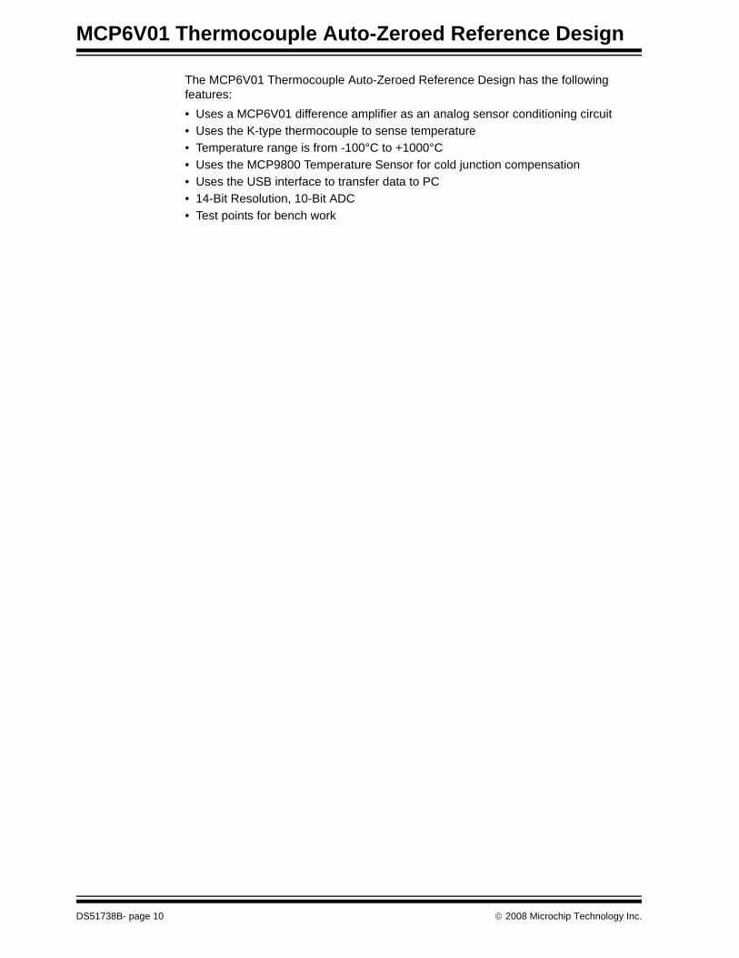
The MCP6V01 Thermocouple Auto-Zeroed Reference Design has the following features:• Uses a MCP6V01 difference amplifier as an analog sensor conditioning circuit• Uses the K-type thermocouple to sense temperature• Temperature range is from -100°C to +1000°C• Uses the MCP9800 Temperature Sensor for cold junction compensation• Uses the USB interface to transfer data to PC• 14-Bit Resolution, 10-Bit ADC• Test points for bench work
DS51738B- page 10 © 2008 Microchip Technology Inc.

MCP6V01 THERMOCOUPLEAUTO-ZEROED REFERENCE DESIGN
Chapter 2. Installation and Operation
2.1 INTRODUCTIONThis chapter shows how to set up the MCP6V01 Thermocouple Auto-Zeroed Refer-ence Design and explores the operation of a temperature measurement application.Items discussed in this chapter include:• Required Tools• MCP6V01 Thermocouple Auto-Zeroed Reference Design Setup• MCP6V01 Thermocouple Auto-Zeroed Reference Design Operation
2.2 REQUIRED TOOL• The Personal Computer (PC) shown in Figure 1-2 needs to run on Windows® 98
SE or later. It provides a convenient interface for the user, communicates with the boards, and provides power through the USB connection.
2.3 MCP6V01 THERMOCOUPLE AUTO-ZEROED REFERENCE DESIGN SETUP1. Connect the type K thermocouple and the USB cable to the MCP6V01 Thermo-
couple Auto-Zeroed Reference Design. An exploded view is shown in the Figure 2-1.
FIGURE 2-1: MCP6V01 Thermocouple Auto-Zeroed Reference Design Setup.
© 2008 Microchip Technology Inc. DS51738B-page 11

MCP6V01 Thermocouple Auto-Zeroed Reference Design
2.4 MCP6V01 THERMOCOUPLE AUTO-ZEROED REFERENCE DESIGN OPERATION
1. Start the Thermal Management Software on the PC.If the hardware is connected properly, the software will recognize the hardware and this is confirmed by showing the Thermocouple Instrumentation GUI Using MCP6V01 panel, as indicated in Figure 2-2. Otherwise, the software will show the Hardware Not Detected message box, as indicated in Figure 2-3.
FIGURE 2-2: Thermocouple Instrumentation GUI Using MCP6V01.
FIGURE 2-3: Hardware Not Detected Message Box.
DS51738B-page 12 © 2008 Microchip Technology Inc.

Installation and Operation
2.4.1 Set Up the MCP9800 Temperature Sensor Configuration1. Click the MCP9800 Setup tab.2. The MCP9800 Configuration can be modified from the default values.3. Click the Update Temp. button to complete the modifications.
FIGURE 2-4: MCP9800 Setup.
© 2008 Microchip Technology Inc. DS51738B-page 13

MCP6V01 Thermocouple Auto-Zeroed Reference Design
2.4.2 Set Up the Thermocouple Configuration1. Click the Thermocouple Setup tab.2. Enable thermocouple is selected as default. Enable Calibration also can be
selected.3. Click the Update button to complete the setup.
.
FIGURE 2-5: Thermocouple setup.
DS51738B-page 14 © 2008 Microchip Technology Inc.

Installation and Operation
2.4.3 Customize the Realtime Data Aquisition1. Double click on the region of the stipchart to customize the Realtime Data Aqui-
sition..
FIGURE 2-6: Realtime Data Aquisition Customization.
© 2008 Microchip Technology Inc. DS51738B-page 15

MCP6V01 Thermocouple Auto-Zeroed Reference Design
2.4.3.1 START THE REALTIME DATA AQUISITION
1. Click the PLAY button to start the Realtime Data Aquisition.
FIGURE 2-7: Start Realtime Data Aquisition.
DS51738B-page 16 © 2008 Microchip Technology Inc.

MCP6V01 THERMOCOUPLEAUTO-ZEROED REFERENCE DESIGN
Appendix A. Schematic and Layout
A.1 INTRODUCTIONThis appendix contains the following schematics and layouts for the MCP6V01 Ther-mocouple Auto-Zeroed Reference Design:• Board – Schematic• Board – Top Silk Layer• Board – Top Metal Layer• Board – Metal Layer 2• Board – Metal Layer 3• Board – Bottom Silk Layer• Board – Bottom Metal Layer
© 2008 Microchip Technology Inc. DS51738B-page 17

MCP6V01 Thermocouple Auto-Zeroed Reference Design
A.2 BOARD - SCHEMATIC
M
DS51738B-page 18 © 2008 Microchip Technology Inc.

Schematic and Layout
A.3 BOARD - TOP SILK LAYER
A.4 BOARD - TOP METAL LAYER
© 2008 Microchip Technology Inc. DS51738B-page 19

MCP6V01 Thermocouple Auto-Zeroed Reference Design
A.5 BOARD - METAL LAYER 2
A.6 BOARD - METAL LAYER 3
DS51738B-page 20 © 2008 Microchip Technology Inc.

Schematic and Layout
A.7 BOARD - BOTTOM SILK LAYER (BOTTOM VIEW)
A.8 BOARD - BOTTOM METAL LAYER
© 2008 Microchip Technology Inc. DS51738B-page 21

MCP6V01 Thermocouple Auto-Zeroed Reference Design
NOTES:
DS51738B-page 22 © 2008 Microchip Technology Inc.

MCP6V01 THERMOCOUPLEAUTO-ZEROED REFERENCE DESIGN
Appendix B. Bill Of Materials (BOM)
TABLE B-1: BILL OF MATERIALS (BOM)Qty Reference Description Manufacturer Part Number
5 C1, C6, C7, C13, C14
CAP .1UF 25V CERAMIC X7R 0805
Panasonic® - ECG ECJ-2VB1E104K
1 C2 CAP 1.0UF 25V CERAMIC F 0805
Panasonic - ECG ECJ-2FF1E105Z
2 C3, C4 CAP CER 10UF 16V Y5V 0805 Murata Electronics® North America
GRM21BF51C106ZE15L
1 C5 CAP 1.0UF 25V CERAMIC F 0603
Panasonic - ECG ECJ-1VF1E105Z
1 C8 CAP .47UF 25V CERAMIC Y5V 0805
Panasonic - ECG ECJ-2YF1E474Z
2 C9, C10 CAP 22PF 50V CERM CHIP 0805 SMD
Panasonic - ECG ECJ-2VC1H220J
2 C11, C12 CAP .1UF 25V CERAMIC X7R 0603
Panasonic - ECG ECJ-1VB1E104K
1 J1 Circuit Board Thermocouple Connectors, Standard
OMEGA PCC-SMP-K-100
1 J2 HEADER 1X6DO NOT POPULATE
— —
1 J3 CONN RECEPT MINI USB2.0 5POS
Hirose Electronic Co Ltd UX60-MB-5ST
1 L1 INDUCTOR 10UH 100MA 0805 Murata Electronics North America
LQM21FN100M70L
1 PCB RoHS Compliant Bare PCB, Thermocouple Auto-Zero RD Board
— 104-00169
3 R1, R2, R5 RES 10.0K OHM 1/8W 1% 0805 SMD
Panasonic - ECG ERJ-6ENF1002V
1 R3 RES 1.0 OHM 1/8W 1% 0805 SMD
Panasonic - ECG ERJ-6RQF1R0V
1 R4 RES 100K OHM 1/8W 1% 0805 SMD
Panasonic - ECG ERJ-6ENF1003V
2 R6, R7 RES 100 OHM 1/10W 0.1% 0805 SMD
Panasonic - ECG ERA-6AEB101V
2 R8, R11 RES 100K OHM 1/10W 0.1% 0805 SMD
Panasonic - ECG ERA-6AEB104V
2 R9, R10 RES 5.6K OHM 1/10W 0.1% 0805 SMD
Panasonic - ECG ERA-6AEB562V
2 R12, R13 RES 499 OHM 1/8W 1% 0805 SMD
Panasonic - ECG ERJ-6ENF4990V
Note 1: The components listed in this Bill of Materials are representative of the PCB assembly. The released BOM used in manufacturing uses all RoHS-compliant components.
© 2008 Microchip Technology Inc. DS51738B-page 23

MCP6V01 Thermocouple Auto-Zeroed Reference Design
3 R14, R15, R16 RES 1.0K OHM 1/10W 1% 0603 SMD
Panasonic - ECG ERJ-3EKF1001V
1 Thermocouples (5 Per Pack)
Ready-Made Insulated Thermo-couples with Kapton, PFA, Glass Braid Insulation and Molded Connectors
OMEGA 5SRTC-TT-K-24-36 (5 Pcs. Per Pack)
10 TP1---TP10 TEST POINT PC COMPACT SMT
Keystone Electronics® 5016
1 U1 28/40/44-Pin, High-Perfor-mance, Enhanced Flash, USB Microcontrollers with nanoWatt Technology
Microchip Technology Inc. PIC18F2550-I/SO
1 U2 4.096V Voltage Reference Microchip Technology Inc. MCP1541T-I/TT1 U3 Memory Module Digital Temper-
ature Sensor, MCP9800Microchip Technology Inc. MCP9800A0T-M/OTG
1 U4 MCP6001, SOT-23-5 Microchip Technology Inc. MCP6001T-I/OT1 U5 MCP60V1, SOIC-8 Microchip Technology Inc. MCP6V01T-E/SN1 Y1 CRYSTAL 20.0000 MHZ
SERIES SMTCTS-Frequency Controls ATS200SM
TABLE B-1: BILL OF MATERIALS (BOM) (CONTINUED)Qty Reference Description Manufacturer Part Number
Note 1: The components listed in this Bill of Materials are representative of the PCB assembly. The released BOM used in manufacturing uses all RoHS-compliant components.
DS51738B-page 24 © 2008 Microchip Technology Inc.

Bill Of Materials (BOM)
NOTES:
© 2008 Microchip Technology Inc. DS51738B-page 25

DS51738B-page 26 © 2008 Microchip Technology Inc.
AMERICASCorporate Office2355 West Chandler Blvd.Chandler, AZ 85224-6199Tel: 480-792-7200 Fax: 480-792-7277Technical Support: http://support.microchip.comWeb Address: www.microchip.comAtlantaDuluth, GA Tel: 678-957-9614 Fax: 678-957-1455BostonWestborough, MA Tel: 774-760-0087 Fax: 774-760-0088ChicagoItasca, IL Tel: 630-285-0071 Fax: 630-285-0075DallasAddison, TX Tel: 972-818-7423 Fax: 972-818-2924DetroitFarmington Hills, MI Tel: 248-538-2250Fax: 248-538-2260KokomoKokomo, IN Tel: 765-864-8360Fax: 765-864-8387Los AngelesMission Viejo, CA Tel: 949-462-9523 Fax: 949-462-9608Santa ClaraSanta Clara, CA Tel: 408-961-6444Fax: 408-961-6445TorontoMississauga, Ontario, CanadaTel: 905-673-0699 Fax: 905-673-6509
ASIA/PACIFICAsia Pacific OfficeSuites 3707-14, 37th FloorTower 6, The GatewayHarbour City, KowloonHong KongTel: 852-2401-1200Fax: 852-2401-3431Australia - SydneyTel: 61-2-9868-6733Fax: 61-2-9868-6755China - BeijingTel: 86-10-8528-2100 Fax: 86-10-8528-2104China - ChengduTel: 86-28-8665-5511Fax: 86-28-8665-7889China - Hong Kong SARTel: 852-2401-1200 Fax: 852-2401-3431China - NanjingTel: 86-25-8473-2460Fax: 86-25-8473-2470China - QingdaoTel: 86-532-8502-7355Fax: 86-532-8502-7205China - ShanghaiTel: 86-21-5407-5533 Fax: 86-21-5407-5066China - ShenyangTel: 86-24-2334-2829Fax: 86-24-2334-2393China - ShenzhenTel: 86-755-8203-2660 Fax: 86-755-8203-1760China - WuhanTel: 86-27-5980-5300Fax: 86-27-5980-5118China - XiamenTel: 86-592-2388138 Fax: 86-592-2388130China - XianTel: 86-29-8833-7252Fax: 86-29-8833-7256China - ZhuhaiTel: 86-756-3210040 Fax: 86-756-3210049
ASIA/PACIFICIndia - BangaloreTel: 91-80-4182-8400 Fax: 91-80-4182-8422India - New DelhiTel: 91-11-4160-8631Fax: 91-11-4160-8632India - PuneTel: 91-20-2566-1512Fax: 91-20-2566-1513Japan - YokohamaTel: 81-45-471- 6166 Fax: 81-45-471-6122Korea - DaeguTel: 82-53-744-4301Fax: 82-53-744-4302Korea - SeoulTel: 82-2-554-7200Fax: 82-2-558-5932 or 82-2-558-5934Malaysia - Kuala LumpurTel: 60-3-6201-9857Fax: 60-3-6201-9859Malaysia - PenangTel: 60-4-227-8870Fax: 60-4-227-4068Philippines - ManilaTel: 63-2-634-9065Fax: 63-2-634-9069SingaporeTel: 65-6334-8870Fax: 65-6334-8850Taiwan - Hsin ChuTel: 886-3-572-9526Fax: 886-3-572-6459Taiwan - KaohsiungTel: 886-7-536-4818Fax: 886-7-536-4803Taiwan - TaipeiTel: 886-2-2500-6610 Fax: 886-2-2508-0102Thailand - BangkokTel: 66-2-694-1351Fax: 66-2-694-1350
EUROPEAustria - WelsTel: 43-7242-2244-39Fax: 43-7242-2244-393Denmark - CopenhagenTel: 45-4450-2828 Fax: 45-4485-2829France - ParisTel: 33-1-69-53-63-20 Fax: 33-1-69-30-90-79Germany - MunichTel: 49-89-627-144-0 Fax: 49-89-627-144-44Italy - Milan Tel: 39-0331-742611 Fax: 39-0331-466781Netherlands - DrunenTel: 31-416-690399 Fax: 31-416-690340Spain - MadridTel: 34-91-708-08-90Fax: 34-91-708-08-91UK - WokinghamTel: 44-118-921-5869Fax: 44-118-921-5820
WORLDWIDE SALES AND SERVICE
01/02/08