Embed Size (px)
Citation preview
© 2009 Microchip Technology Inc. DS51798A
MCP1631HVDigitally Controlled
Programmable Current SourceReference Design
Note the following details of the code protection feature on Microchip devices:• Microchip products meet the specification contained in their particular Microchip Data Sheet.
• Microchip believes that its family of products is one of the most secure families of its kind on the market today, when used in the intended manner and under normal conditions.
• There are dishonest and possibly illegal methods used to breach the code protection feature. All of these methods, to our knowledge, require using the Microchip products in a manner outside the operating specifications contained in Microchip’s Data Sheets. Most likely, the person doing so is engaged in theft of intellectual property.
• Microchip is willing to work with the customer who is concerned about the integrity of their code.
• Neither Microchip nor any other semiconductor manufacturer can guarantee the security of their code. Code protection does not mean that we are guaranteeing the product as “unbreakable.”
Code protection is constantly evolving. We at Microchip are committed to continuously improving the code protection features of ourproducts. Attempts to break Microchip’s code protection feature may be a violation of the Digital Millennium Copyright Act. If such actsallow unauthorized access to your software or other copyrighted work, you may have a right to sue for relief under that Act.
Information contained in this publication regarding deviceapplications and the like is provided only for your convenienceand may be superseded by updates. It is your responsibility toensure that your application meets with your specifications.MICROCHIP MAKES NO REPRESENTATIONS ORWARRANTIES OF ANY KIND WHETHER EXPRESS ORIMPLIED, WRITTEN OR ORAL, STATUTORY OROTHERWISE, RELATED TO THE INFORMATION,INCLUDING BUT NOT LIMITED TO ITS CONDITION,QUALITY, PERFORMANCE, MERCHANTABILITY ORFITNESS FOR PURPOSE. Microchip disclaims all liabilityarising from this information and its use. Use of Microchipdevices in life support and/or safety applications is entirely atthe buyer’s risk, and the buyer agrees to defend, indemnify andhold harmless Microchip from any and all damages, claims,suits, or expenses resulting from such use. No licenses areconveyed, implicitly or otherwise, under any Microchipintellectual property rights.
DS51798A-page ii
Trademarks
The Microchip name and logo, the Microchip logo, Accuron, dsPIC, KEELOQ, KEELOQ logo, MPLAB, PIC, PICmicro, PICSTART, rfPIC, SmartShunt and UNI/O are registered trademarks of Microchip Technology Incorporated in the U.S.A. and other countries.
FilterLab, Hampshire, Linear Active Thermistor, MXDEV, MXLAB, SEEVAL, SmartSensor and The Embedded Control Solutions Company are registered trademarks of Microchip Technology Incorporated in the U.S.A.
Analog-for-the-Digital Age, Application Maestro, CodeGuard, dsPICDEM, dsPICDEM.net, dsPICworks, dsSPEAK, ECAN, ECONOMONITOR, FanSense, In-Circuit Serial Programming, ICSP, ICEPIC, Mindi, MiWi, MPASM, MPLAB Certified logo, MPLIB, MPLINK, mTouch, nanoWatt XLP, PICkit, PICDEM, PICDEM.net, PICtail, PIC32 logo, PowerCal, PowerInfo, PowerMate, PowerTool, REAL ICE, rfLAB, Select Mode, Total Endurance, TSHARC, WiperLock and ZENA are trademarks of Microchip Technology Incorporated in the U.S.A. and other countries.
SQTP is a service mark of Microchip Technology Incorporated in the U.S.A.
All other trademarks mentioned herein are property of their respective companies.
© 2009, Microchip Technology Incorporated, Printed in the U.S.A., All Rights Reserved.
Printed on recycled paper.
© 2009 Microchip Technology Inc.
Microchip received ISO/TS-16949:2002 certification for its worldwide headquarters, design and wafer fabrication facilities in Chandler and Tempe, Arizona; Gresham, Oregon and design centers in California and India. The Company’s quality system processes and procedures are for its PIC® MCUs and dsPIC® DSCs, KEELOQ® code hopping devices, Serial EEPROMs, microperipherals, nonvolatile memory and analog products. In addition, Microchip’s quality system for the design and manufacture of development systems is ISO 9001:2000 certified.
MCP1631HV DIGITALLY CONTROLLEDPROGRAMMABLE CURRENT SOURCE
REFERENCE DESIGN
Table of Contents
Preface ........................................................................................................................... 1Introduction............................................................................................................ 1Document Layout .................................................................................................. 1Conventions Used in this Guide ............................................................................ 2Recommended Reading........................................................................................ 3The Microchip Web Site ........................................................................................ 3Customer Support ................................................................................................. 3Document Revision History ................................................................................... 4
Chapter 1. Product Overview1.1 Introduction ..................................................................................................... 51.2 What is the MCP1631HV Digitally Controlled Programmable Current
Source Reference Design? ...................................................................... 61.3 What the MCP1631HV Digitally Controlled Programmable Current
Source Kit Includes ................................................................................... 6Chapter 2. Installation and Operation
2.1 Introduction ..................................................................................................... 72.2 Features ......................................................................................................... 72.3 Getting Started ............................................................................................... 8
Appendix A. Schematic and LayoutsA.1 Introduction .................................................................................................. 17A.2 Board – Schematic ....................................................................................... 18A.3 Board – Top Solder Pads and Silk-Screen Layers ...................................... 19A.4 Board – Top Copper Layer .......................................................................... 20A.5 Board – Bottom Copper Layer ..................................................................... 21
Appendix B. Bill Of Materials (BOM)Appendix C. Demo Board Firmware
C.1 Summary Device Firmware Flowchart - LED Driver .................................... 25C.2 Summary Device Firmware Flowchart - Li-Ion Charger ............................... 26C.3 Summary Device Firmware Flowchart - NiMH/NiCd Charger ...................... 27
Worldwide Sales and Service .................................................................................... 28
© 2009 Microchip Technology Inc. DS51798A-page iii

MCP1631HV Digitally Controlled Programmable Current Source Reference Design
NOTES:
DS51798A-page iv © 2009 Microchip Technology Inc.
MCP1631HV DIGITALLY CONTROLLEDPROGRAMMABLE CURRENT SOURCE
REFERENCE DESIGN
Preface
INTRODUCTIONThis chapter contains general information that will be useful to know before using the MCP1631HV Digitally Controlled Programmable Current Source Reference Design. Items discussed in this chapter include:• Document Layout• Conventions Used in this Guide• Recommended Reading• The Microchip Web Site• Customer Support• Document Revision History
DOCUMENT LAYOUTThis document describes how to use the MCP1631HV Digitally Controlled Programmable Current Source Reference Design as a LED driver or a battery charger. The manual layout is as follows:• Chapter 1. “Product Overview” – Important information about the MCP1631HV
Digitally Controlled Programmable Current Source Reference Design.• Chapter 2. “Installation and Operation” – Includes instructions on how to get
started with this user’s guide and a description of the user’s guide.• Appendix A. “Schematic and Layouts” – Shows the schematic and layout
diagrams for the MCP1631HV Digitally Controlled Programmable Current Source Reference Design.
• Appendix B. “Bill Of Materials (BOM)” – Lists the parts used to build the MCP1631HV Digitally Controlled Programmable Current Source Reference Design.
• Appendix C. “Demo Board Firmware” – Provides general information about the application firmware flowcharts and where the source code can be found.
NOTICE TO CUSTOMERS
All documentation becomes dated, and this manual is no exception. Microchip tools and documentation are constantly evolving to meet customer needs, so some actual dialogs and/or tool descriptions may differ from those in this document. Please refer to our web site (www.microchip.com) to obtain the latest documentation available.
Documents are identified with a “DS” number. This number is located on the bottom of each page, in front of the page number. The numbering convention for the DS number is “DSXXXXXA”, where “XXXXX” is the document number and “A” is the revision level of the document.
For the most up-to-date information on development tools, see the MPLAB® IDE on-line help. Select the Help menu, and then Topics to open a list of available on-line help files.
© 2009 Microchip Technology Inc. DS51798A-page 1
MCP1631HV Digitally Controlled Programmable Current Source Reference Design
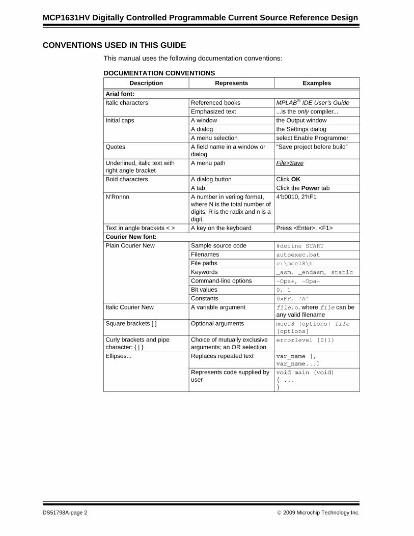
CONVENTIONS USED IN THIS GUIDEThis manual uses the following documentation conventions:
DOCUMENTATION CONVENTIONSDescription Represents Examples
Arial font:Italic characters Referenced books MPLAB® IDE User’s Guide
Emphasized text ...is the only compiler...Initial caps A window the Output window
A dialog the Settings dialogA menu selection select Enable Programmer
Quotes A field name in a window or dialog
“Save project before build”
Underlined, italic text with right angle bracket
A menu path File>Save
Bold characters A dialog button Click OKA tab Click the Power tab
N‘Rnnnn A number in verilog format, where N is the total number of digits, R is the radix and n is a digit.
4‘b0010, 2‘hF1
Text in angle brackets < > A key on the keyboard Press <Enter>, <F1>Courier New font:Plain Courier New Sample source code #define START
Filenames autoexec.batFile paths c:\mcc18\h
Keywords _asm, _endasm, static
Command-line options -Opa+, -Opa-Bit values 0, 1
Constants 0xFF, ‘A’
Italic Courier New A variable argument file.o, where file can be any valid filename
Square brackets [ ] Optional arguments mcc18 [options] file [options]
Curly brackets and pipe character: { | }
Choice of mutually exclusive arguments; an OR selection
errorlevel {0|1}
Ellipses... Replaces repeated text var_name [, var_name...]
Represents code supplied by user
void main (void){ ...}
DS51798A-page 2 © 2009 Microchip Technology Inc.
Preface
RECOMMENDED READINGThis user's guide describes how to use the MCP1631HV Digitally Controlled Programmable Current Source Reference Design. Other useful documents are listed below. The following Microchip documents are available and recommended as supplemental reference resources.MCP1631 Data Sheet, "High-Speed, Microcontroller-Adaptable, Pulse Width Modulator", DS22063AThis data sheet provides detailed information regarding the MCP1631/MCP1631V, MCP1631HV and MCP1631VHV product families.PIC16F616/HV616 Data Sheet, "14-Pin Flash-Based, 8-Bit CMOS Microcontrollers”, DS41288AThis data sheet provides detailed information regarding the PIC16F616 product family.AN1137 Application Note, “Using the MCP1631 Family to Develop Low-Cost Battery Chargers”, DS01137A.
THE MICROCHIP WEB SITEMicrochip provides online support via our web site at www.microchip.com. This web site is used as a means to make files and information easily available to customers. Accessible by using your favorite Internet browser, the web site contains the following information:• Product Support – Data sheets and errata, application notes and sample
programs, design resources, user’s guides and hardware support documents, latest software releases and archived software
• General Technical Support – Frequently Asked Questions (FAQs), technical support requests, online discussion groups, Microchip consultant program member listing
• Business of Microchip – Product selector and ordering guides, latest Microchip press releases, listing of seminars and events, listings of Microchip sales offices, distributors and factory representatives
CUSTOMER SUPPORTUsers of Microchip products can receive assistance through several channels:• Distributor or Representative• Local Sales Office• Field Application Engineer (FAE)• Technical SupportCustomers should contact their distributor, representative or field application engineer (FAE) for support. Local sales offices are also available to help customers. A listing of sales offices and locations is included in the back of this document.Technical support is available through the web site at: http://support.microchip.com.
© 2009 Microchip Technology Inc. DS51798A-page 3
MCP1631HV Digitally Controlled Programmable Current Source Reference Design
DOCUMENT REVISION HISTORY
Revision A (May 2009)• Initial Release of this Document.
DS51798A-page 4 © 2009 Microchip Technology Inc.
MCP1631HV DIGITALLY CONTROLLEDPROGRAMMABLE CURRENT SOURCE
REFERENCE DESIGN
Chapter 1. Product Overview
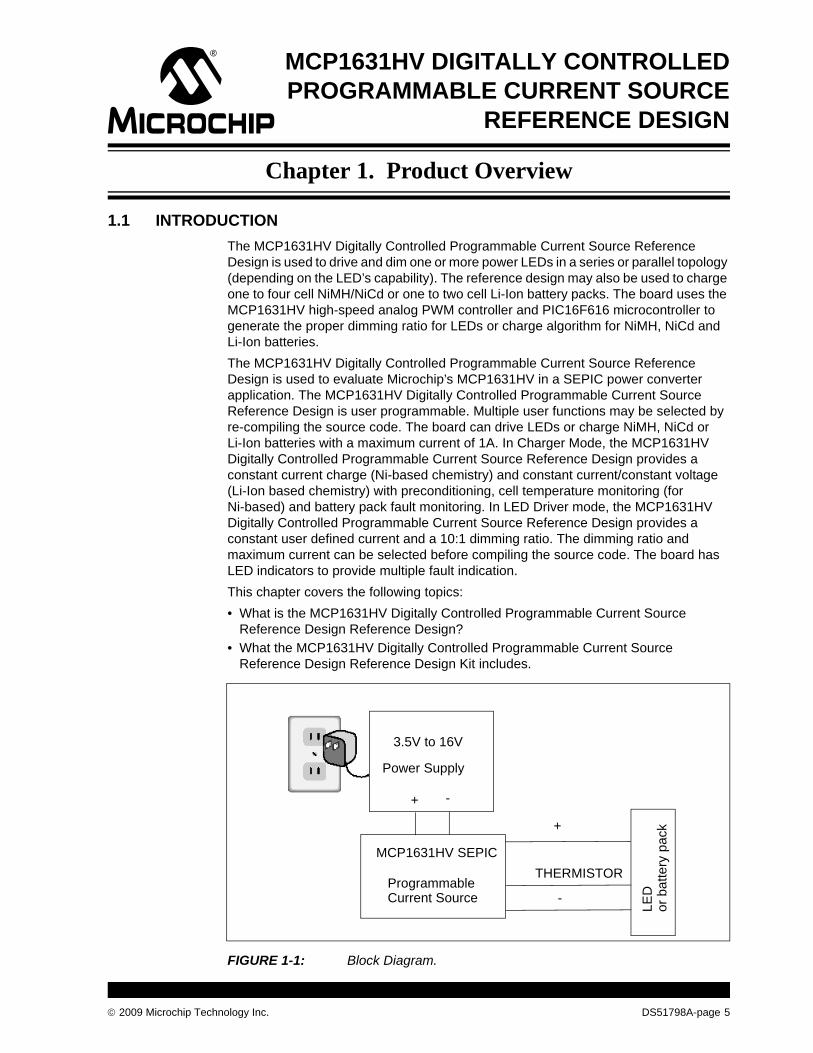
1.1 INTRODUCTIONThe MCP1631HV Digitally Controlled Programmable Current Source Reference Design is used to drive and dim one or more power LEDs in a series or parallel topology (depending on the LED’s capability). The reference design may also be used to charge one to four cell NiMH/NiCd or one to two cell Li-Ion battery packs. The board uses the MCP1631HV high-speed analog PWM controller and PIC16F616 microcontroller to generate the proper dimming ratio for LEDs or charge algorithm for NiMH, NiCd and Li-Ion batteries.The MCP1631HV Digitally Controlled Programmable Current Source Reference Design is used to evaluate Microchip’s MCP1631HV in a SEPIC power converter application. The MCP1631HV Digitally Controlled Programmable Current Source Reference Design is user programmable. Multiple user functions may be selected by re-compiling the source code. The board can drive LEDs or charge NiMH, NiCd or Li-Ion batteries with a maximum current of 1A. In Charger Mode, the MCP1631HV Digitally Controlled Programmable Current Source Reference Design provides a constant current charge (Ni-based chemistry) and constant current/constant voltage (Li-Ion based chemistry) with preconditioning, cell temperature monitoring (for Ni-based) and battery pack fault monitoring. In LED Driver mode, the MCP1631HV Digitally Controlled Programmable Current Source Reference Design provides a constant user defined current and a 10:1 dimming ratio. The dimming ratio and maximum current can be selected before compiling the source code. The board has LED indicators to provide multiple fault indication. This chapter covers the following topics:• What is the MCP1631HV Digitally Controlled Programmable Current Source
Reference Design Reference Design?• What the MCP1631HV Digitally Controlled Programmable Current Source
Reference Design Reference Design Kit includes.
FIGURE 1-1: Block Diagram.
3.5V to 16V
Power Supply
MCP1631HV SEPIC
Programmable
+ -
+
-
THERMISTOR
LEDCurrent Source
or b
atte
ry p
ack
© 2009 Microchip Technology Inc. DS51798A-page 5
MCP1631HV Digitally Controlled Programmable Current Source Reference Design
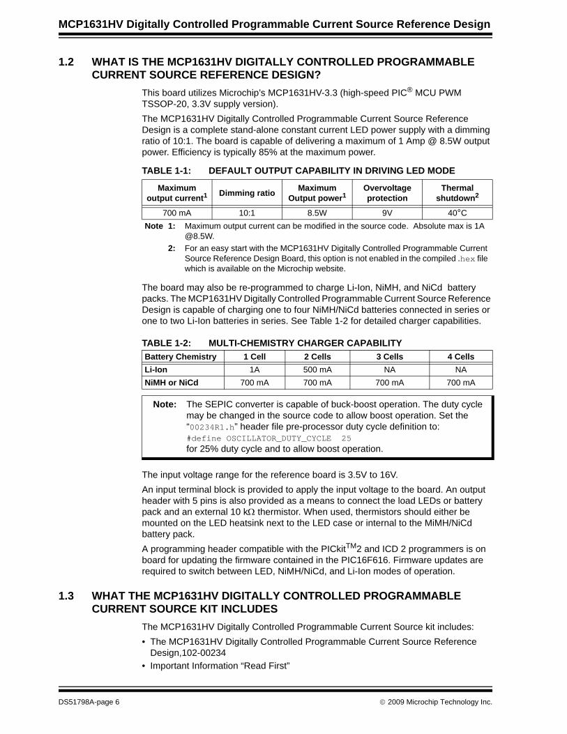
1.2 WHAT IS THE MCP1631HV DIGITALLY CONTROLLED PROGRAMMABLE CURRENT SOURCE REFERENCE DESIGN?
This board utilizes Microchip’s MCP1631HV-3.3 (high-speed PIC® MCU PWM TSSOP-20, 3.3V supply version).The MCP1631HV Digitally Controlled Programmable Current Source Reference Design is a complete stand-alone constant current LED power supply with a dimming ratio of 10:1. The board is capable of delivering a maximum of 1 Amp @ 8.5W output power. Efficiency is typically 85% at the maximum power.
TABLE 1-1: DEFAULT OUTPUT CAPABILITY IN DRIVING LED MODE
The board may also be re-programmed to charge Li-Ion, NiMH, and NiCd battery packs. The MCP1631HV Digitally Controlled Programmable Current Source Reference Design is capable of charging one to four NiMH/NiCd batteries connected in series or one to two Li-Ion batteries in series. See Table 1-2 for detailed charger capabilities.
TABLE 1-2: MULTI-CHEMISTRY CHARGER CAPABILITY
The input voltage range for the reference board is 3.5V to 16V.An input terminal block is provided to apply the input voltage to the board. An output header with 5 pins is also provided as a means to connect the load LEDs or battery pack and an external 10 kΩ thermistor. When used, thermistors should either be mounted on the LED heatsink next to the LED case or internal to the MiMH/NiCd battery pack.A programming header compatible with the PICkitTM2 and ICD 2 programmers is on board for updating the firmware contained in the PIC16F616. Firmware updates are required to switch between LED, NiMH/NiCd, and Li-Ion modes of operation.
1.3 WHAT THE MCP1631HV DIGITALLY CONTROLLED PROGRAMMABLE CURRENT SOURCE KIT INCLUDES
The MCP1631HV Digitally Controlled Programmable Current Source kit includes:• The MCP1631HV Digitally Controlled Programmable Current Source Reference
Design,102-00234• Important Information “Read First”
Maximum output current1 Dimming ratio Maximum
Output power1Overvoltage protection
Thermal shutdown2
700 mA 10:1 8.5W 9V 40°CNote 1: Maximum output current can be modified in the source code. Absolute max is 1A
@8.5W.2: For an easy start with the MCP1631HV Digitally Controlled Programmable Current
Source Reference Design Board, this option is not enabled in the compiled .hex file which is available on the Microchip website.
Battery Chemistry 1 Cell 2 Cells 3 Cells 4 CellsLi-Ion 1A 500 mA NA NANiMH or NiCd 700 mA 700 mA 700 mA 700 mA
Note: The SEPIC converter is capable of buck-boost operation. The duty cycle may be changed in the source code to allow boost operation. Set the “00234R1.h” header file pre-processor duty cycle definition to:#define OSCILLATOR_DUTY_CYCLE 25for 25% duty cycle and to allow boost operation.
DS51798A-page 6 © 2009 Microchip Technology Inc.
MCP1631HV DIGITALLY CONTROLLEDPROGRAMMABLE CURRENT SOURCE
REFERENCE DESIGN
Chapter 2. Installation and Operation
2.1 INTRODUCTIONThe MCP1631HV Digitally Controlled Programmable Current Source Reference Design demonstrates Microchip’s MCP1631HV high-speed Pulse Width Modulator (PWM) used in LED lighting and multi-chemistry battery charger applications. When used in conjunction with a microcontroller, the MCP1631HV will control the power system duty cycle to provide output voltage or current regulation. A PIC16F616 microcontroller is used to provide the MCP1631HV switching frequency oscillator and reference voltage. The MCP1631HV generates a duty cycle and provides fast overcurrent protection based upon the feedback and current sense inputs. MCP1631HV external signals include the input oscillator, the reference voltage, the feedback voltage and the current sense. The MCP1631HV generates a square-wave output signal to drive the powertrain switch. The power train used for the MCP1631HV Digitally Controlled Programmable Current Source Reference Design is a Single-Ended Primary Inductive Converter (SEPIC). The PIC16F616 microcontroller is programmable, allowing the user to modify or develop their own firmware routines to further evaluate the MCP1631HV Digitally Controlled Programmable Current Source Reference Design in this application.
2.2 FEATURESThe MCP1631HV Digitally Controlled Programmable Current Source Reference Design has the following features:• Input Operating Voltage Range: +3.5V to +16V• Firmware default output current of 700 mA with dimming ratio 10:1 (70 mA/step)• Maximum output current of 1000 mA• Maximum output power of 8.5W• Drive one or more LEDs• Firmware for charging Li-Ion, NiMH, and NiCd batteries• ON/OFF/Dimming switch• Status and fault indication• Hardware and software overvoltage protection (OVP) set to 9.0V. The software
value can be modified in the source code to be less than 9.0V
© 2009 Microchip Technology Inc. DS51798A-page 7
MCP1631HV Digitally Controlled Programmable Current Source Reference Design
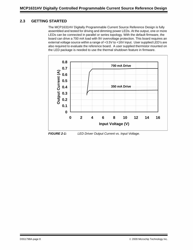
2.3 GETTING STARTEDThe MCP1631HV Digitally Programmable Current Source Reference Design is fully assembled and tested for driving and dimming power LEDs. At the output, one or more LEDs can be connected in parallel or series topology. With the default firmware, the board can drive a 700 mA load with 9V overvoltage protection. This board requires an external voltage source within a range of +3.5V to +16V input. User supplied LED’s are also required to evaluate the reference board. A user supplied thermistor mounted on the LED package is needed to use the thermal shutdown feature in firmware.
FIGURE 2-1: LED Driver Output Current vs. Input Voltage.
00.10.20.30.40.50.60.70.8
0 2 4 6 8 10 12 14 16Input Voltage (V)
Out
put C
urre
nt (A
)
700 mA Drive
350 mA Drive
DS51798A-page 8 © 2009 Microchip Technology Inc.
Installation and Operation
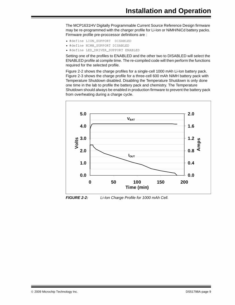
The MCP1631HV Digitally Programmable Current Source Reference Design firmware may be re-programmed with the charger profile for Li-Ion or NiMH/NiCd battery packs. Firmware profile pre-proccessor definitions are :• #define LION_SUPPORT DISABLED• #define NIMH_SUPPORT DISABLED• #define LED_DRIVER_SUPPORT ENABLED
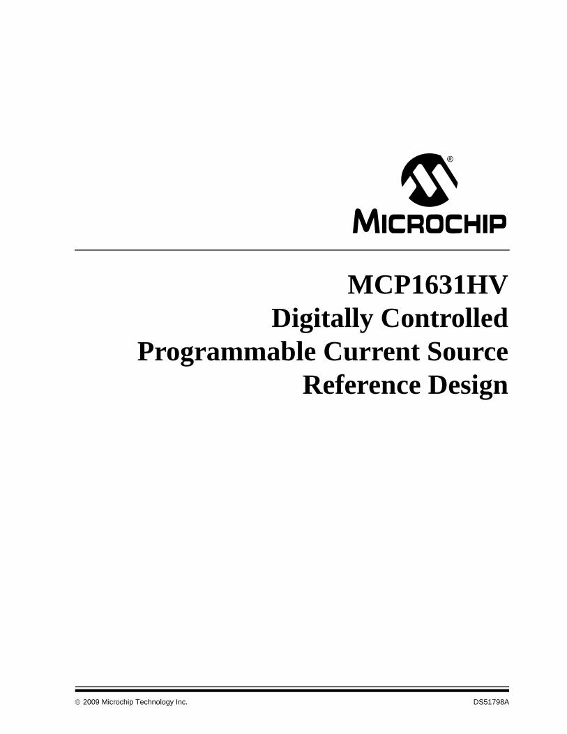
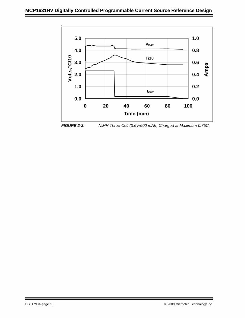
Setting one of the profiles to ENABLED and the other two to DISABLED will select the ENABLED profile at compile time. The re-compiled code will then perform the functions required for the selected profile.Figure 2-2 shows the charge profiles for a single-cell 1000 mAh Li-Ion battery pack. Figure 2-3 shows the charge profile for a three-cell 600 mAh NiMH battery pack with Temperature Shutdown disabled. Disabling the Temperature Shutdown is only done one time in the lab to profile the battery pack and chemistry. The Temperature Shutdown should always be enabled in production firmware to prevent the battery pack from overheating during a charge cycle.
FIGURE 2-2: Li-Ion Charge Profile for 1000 mAh Cell.
0.0
1.0
2.0
3.0
4.0
5.0
0 50 100 150 200Time (min)
Volts
0.0
0.4
0.8
1.2
1.6
2.0
Am
ps
VBAT
IOUT
© 2009 Microchip Technology Inc. DS51798A-page 9
MCP1631HV Digitally Controlled Programmable Current Source Reference Design
I
FIGURE 2-3: NiMH Three-Cell (3.6V/600 mAh) Charged at Maximum 0.75C.
0.0
1.0
2.0
3.0
4.0
5.0
0 20 40 60 80 100Time (min)
Volts
,°C/1
0
0.0
0.2
0.4
0.6
0.8
1.0
Am
ps
T/10
VBAT
IOUT
DS51798A-page 10 © 2009 Microchip Technology Inc.
Installation and Operation
2.3.1 Power Input and Output Connection
2.3.1.1 POWERING THE MCP1631HV DIGITALLY PROGRAMMABLE CURRENT SOURCE REFERENCE DESIGN
1. Prepare the power supply to be connected to the input terminal block, J1. The input voltage source should be limited to the 0V to +16V range. For nominal operations, the recommended input voltage should be between +3.5 and +16 volts with a 12W input supply.
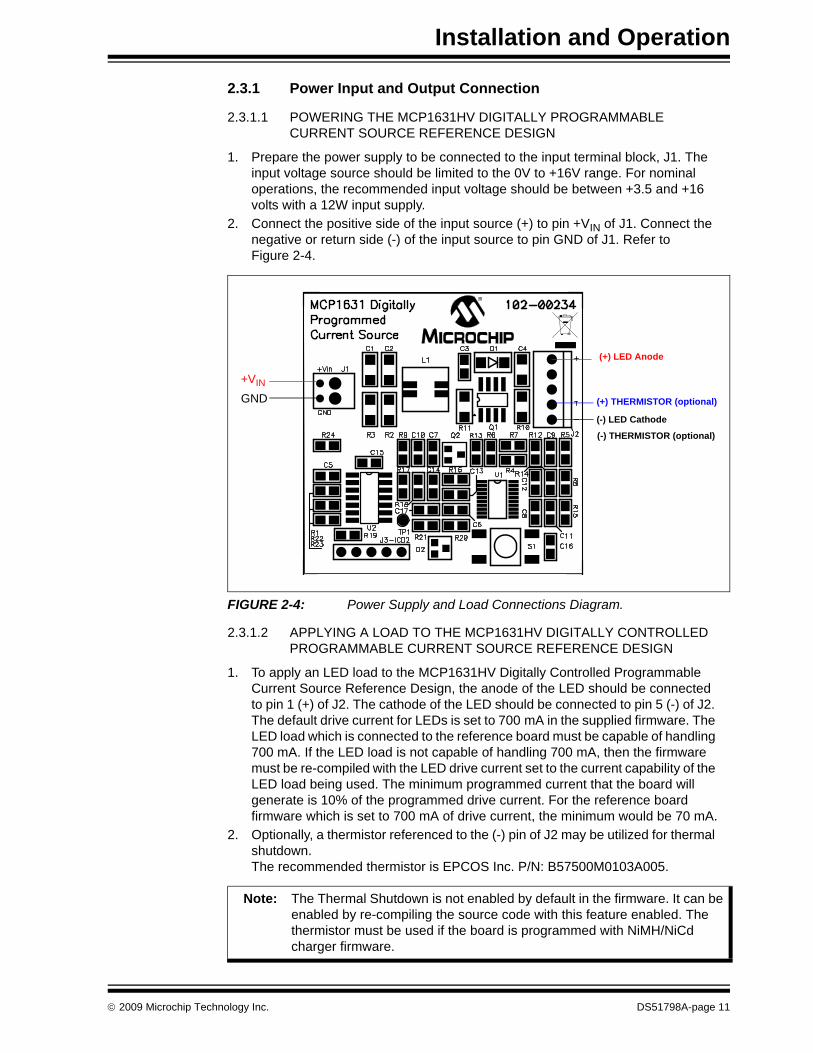
2. Connect the positive side of the input source (+) to pin +VIN of J1. Connect the negative or return side (-) of the input source to pin GND of J1. Refer to Figure 2-4.
FIGURE 2-4: Power Supply and Load Connections Diagram.
2.3.1.2 APPLYING A LOAD TO THE MCP1631HV DIGITALLY CONTROLLED PROGRAMMABLE CURRENT SOURCE REFERENCE DESIGN
1. To apply an LED load to the MCP1631HV Digitally Controlled Programmable Current Source Reference Design, the anode of the LED should be connected to pin 1 (+) of J2. The cathode of the LED should be connected to pin 5 (-) of J2. The default drive current for LEDs is set to 700 mA in the supplied firmware. The LED load which is connected to the reference board must be capable of handling 700 mA. If the LED load is not capable of handling 700 mA, then the firmware must be re-compiled with the LED drive current set to the current capability of the LED load being used. The minimum programmed current that the board will generate is 10% of the programmed drive current. For the reference board firmware which is set to 700 mA of drive current, the minimum would be 70 mA.
2. Optionally, a thermistor referenced to the (-) pin of J2 may be utilized for thermal shutdown.The recommended thermistor is EPCOS Inc. P/N: B57500M0103A005.
(+) LED Anode
(-) LED Cathode
(+) THERMISTOR (optional)GND+VIN
(-) THERMISTOR (optional)
Note: The Thermal Shutdown is not enabled by default in the firmware. It can be enabled by re-compiling the source code with this feature enabled. The thermistor must be used if the board is programmed with NiMH/NiCd charger firmware.
© 2009 Microchip Technology Inc. DS51798A-page 11
MCP1631HV Digitally Controlled Programmable Current Source Reference Design
2.3.1.3 USING THE REFERENCE BOARD
The push button is used to switch the output ON or OFF (Standby). The first pressing of the power button will turn on the board and drive the output at 10% of programmed current (70 mA for the default firmware). The GREEN LED will flash with a 1 second period, indicating that it is in normal operating mode.The board is capable of a 10:1 dimming ratio. Each additional pressing of the power button will increment the output drive current by 10% of the programmed drive current up to the actual programmed drive current value.To switch the output OFF, press and hold the push button for about 2 seconds until the LED turns RED.
2.3.1.4 STATUS AND FAULT INDICATION
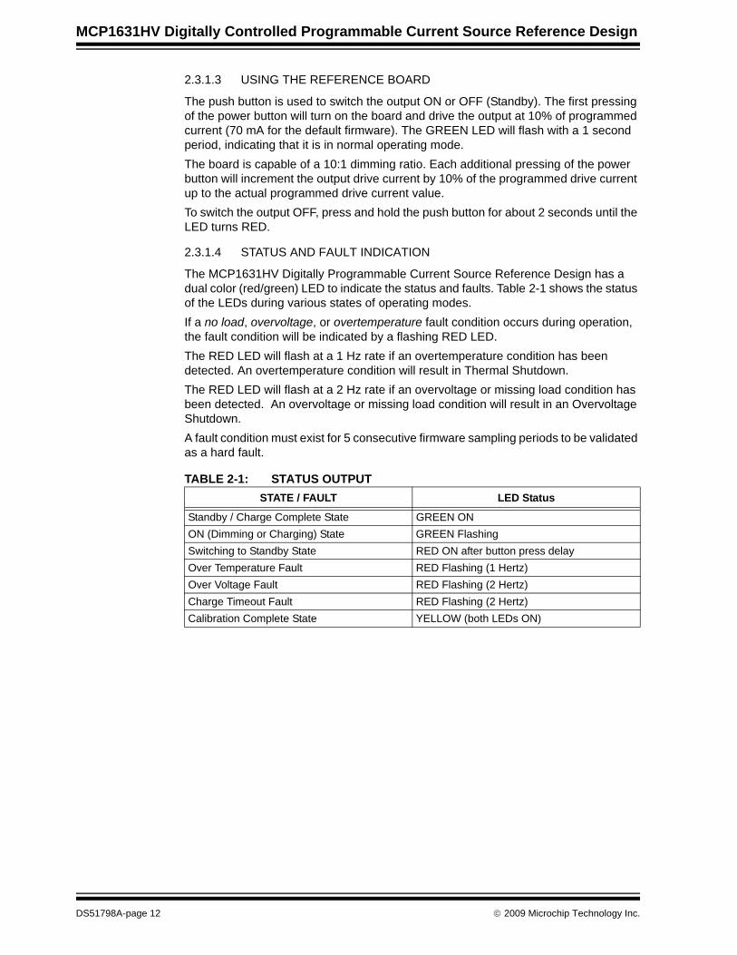
The MCP1631HV Digitally Programmable Current Source Reference Design has a dual color (red/green) LED to indicate the status and faults. Table 2-1 shows the status of the LEDs during various states of operating modes.If a no load, overvoltage, or overtemperature fault condition occurs during operation, the fault condition will be indicated by a flashing RED LED.The RED LED will flash at a 1 Hz rate if an overtemperature condition has been detected. An overtemperature condition will result in Thermal Shutdown.The RED LED will flash at a 2 Hz rate if an overvoltage or missing load condition has been detected. An overvoltage or missing load condition will result in an Overvoltage Shutdown.A fault condition must exist for 5 consecutive firmware sampling periods to be validated as a hard fault.
TABLE 2-1: STATUS OUTPUTSTATE / FAULT LED Status
Standby / Charge Complete State GREEN ONON (Dimming or Charging) State GREEN FlashingSwitching to Standby State RED ON after button press delayOver Temperature Fault RED Flashing (1 Hertz)Over Voltage Fault RED Flashing (2 Hertz)Charge Timeout Fault RED Flashing (2 Hertz)Calibration Complete State YELLOW (both LEDs ON)
DS51798A-page 12 © 2009 Microchip Technology Inc.
Installation and Operation
2.3.1.5 MCP1631 PROGRAMMABLE CURRENT SOURCE AS BATTERY CHARGER
The MCP1631HV Digitally Controlled Programmable Current Source Reference Design reference board is provided with the LED driver firmware programmed into the U2 microcontroller.The reference board package also has compiled firmware *.hex files included for Li-Ion and NiMH/NiCd battery packs. There are two versions of charger firmware. One is for Li-Ion cells (00234R1-LiIon_Charger.hex) and the other is for NiCd/NIMH cells (00234R1-NiMH_NiCd_Charger.hex).
2.3.1.5.1 How to Connect and Charge a Battery with the MCP1631HV Digitally Controlled Programmable Current Source Reference Design
To charge a battery pack with the MCP1631HV Digitally Controlled Programmable Current Source Reference Design, the positive connector of the battery should be connected to J2-1 (+). The negative terminal of the battery should be connected to J2-5 (-).A thermistor referenced to J2-5 (-) should be used for thermal shutdown if the battery chemistry is NiMH/NiCd. To evaluate a NiMH/NiCd battery charger pack that does not have an internal thermistor, it is recommended to attach an EPCOS Inc. P/N: B57500M0103A005 thermistor onto one of the cells of the battery pack. This thermistor should be connected to J2-4 (+) and J2-5 (-).
For evaluation, all charge parameters can be modified in source code. See the header file 00234R1.h for the pre-processor definitions.
2.3.1.5.2 Charge ProfilesThe pre-programmed parameters for the battery charge profiles are:• Li-Ion
- Qualification: Precharge at 200 mA for VCELL < 3.0V- Constant Current: 1A for 1 Cell, 0.5A for 2 Cells- Constant Voltage: 4.20V (this value should be calibrated for better accuracy,
see Section 2.3.1.5.4 “Calibrating the Output Voltage for the Li-Ion Chemistry Profile”)
- Charge Termination: 70 mA for 1 Cell and 2 Cells- Overvoltage Detection: Once detected, attempts to restart the charge cycle 5
times. If overvoltage is still present, the charge cycle is aborted and the RED LED is flashed.
• NiMH/NiCd- Qualification: Precharge at 140 mA for VCELL < 0.9V- Constant Current: 700 mA for 1 Cell to 4 Cell- Terminate Fast Charge for -dV/dT or +dT/dt- Top off Charge Current: 35 mA
Top off Charge Time: 1 hour- Overvoltage Detection: Once detected, attempts to restart the charge cycle 5
times. If overvoltage is still present, the charge cycle is aborted and the RED LED is flashed.
Note: The maximum charge current for the Li-Ion chemistry is programmed and limited at 1A for a single cell (4.2V) or 500 mA for two cells in series topology. The pre-programmed maximum charge current for NiMH/NiCd chemistry is 700 mA.
© 2009 Microchip Technology Inc. DS51798A-page 13
MCP1631HV Digitally Controlled Programmable Current Source Reference Design
2.3.1.5.3 How the MCP1631HV Digitally Controlled Programmable Current Source Reference Design Operates in Charger Mode
Follow the instructions in Section 2.3.1.5.1 “How to Connect and Charge a Battery with the MCP1631HV Digitally Controlled Programmable Current Source Reference Design” to connect a battery pack at the board. In the Standby (OFF) state, the GREEN LED will be lit. Push the S1 button to start the charge profile and turn on the output. The GREEN LED will flash.If any fault conditions are detected during charging, the RED LED will flash and the output will automatically turn off. See Table 2-1 to identify the nature of the fault. When a charge cycle successfully completes, the GREEN LED will be turned ON and the output will be turned off. The system will stay in a Standby (OFF) state until the next button push.At any moment, the charging can be stopped by pressing and holding the push button until the RED LED turns on.The default calibration value for the Li-Ion pack is 4.2V. For better accuracy, the output voltage should be calibrated before starting a charge cycle. See Section 2.3.1.5.4 “Calibrating the Output Voltage for the Li-Ion Chemistry Profile” for instructions.
2.3.1.5.4 Calibrating the Output Voltage for the Li-Ion Chemistry ProfilePrior to the first Li-Ion charging cycle, it is recommended to calibrate the charger termination voltage for better accuracy. Connect a 12V power supply to the J1 connector. Select another power supply for the calibration voltage and set it to the desired termination voltage between 3.9V and 4.20V. Connect the calibration power supply to the J2 connector. Connect the positive lead to J2-1 and the negative lead to J2-5.1. Press S1 to turn on the board.2. Wait for the GREEN LED to light. If it does not light, check for faults.3. When the GREEN LED is lit, press and hold down S1 for 2 seconds until the
YELLOW LED (both green and red LEDs) is lit. The YELLOW status indicator signals the calibration is complete.
4. The calibration power supply can now be removed from the J2 output connector.
DS51798A-page 14 © 2009 Microchip Technology Inc.
Installation and Operation
2.3.1.6 VIEW THE STATE OF MCP1631HV DIGITALLY CONTROLLED PROGRAMMABLE CURRENT SOURCE REFERENCE DESIGN
The MCP1631HV Digitally Controlled Programmable Current Source Reference Design is able to show, using an oscilloscope, the system state. To use this feature, connect the scope probe to test point TP1. Testpoint TP1 is output pin U2-8 of the PIC16F616 microcontroller. There are nine status waveforms listed below. A pulse stream of one to nine 10 µs pulses are generated at TP1 test point every one second interval. The pulse stream indicates the current state of the system software. Note that the first two states may complete immediately and thus may be difficult to capture on a non-storage scope.• 1 pulse - output power is switched ON• 2 pulses - qualification charging• 3 pulses - charging - NiMH / NiCd constant current mode• 4 pulses - charging - NiMH / NiCd top off current mode• 5 pulses - charging - Li-Ion constant current mode• 6 pulses - charging - Li-Ion constant voltage mode• 7 pulses - dimming - LED constant current mode• 8 pulses - fault - overvoltage protection state• 9 pulses - output power switched OFF (Standby)
2.3.1.7 PROGRAMMING THE PIC16F616 MICROCONTROLLER
To evaluate the board, the firmware package provides 3 hex files for the LED driver, Li-Ion Battery Charger, and NiMH/NiCd Battery Charger. The board is factory programmed with the LED driver firmware for 700 mA maximum current and 10:1 dimming (~70 mA/step). All parameters may be changed in firmware to the desired value according to the output capability. The source code is commented extensively and helps the user to define the board.The header file, 00234R1.h, contains the pre-processor definitions which define the system. The user may modify the definitions to change specific system parameters to meet design goals.mikroElektronika’s mikroC compiler was used to compile the source code and create the hex files for downloading to the reference board. The mikroC compiler is available at http://www.mikroe.com. The compiler is not included with the reference board kit.Header J3 is provided for in-system circuit programming. A PICkitTM2 programmer may be connected to J3 to program the reference board.1. Connect the PICkitTM2 programmer to J3.2. Start the PICkitTM2 software.3. Set Device to PIC16F616.4. Erase the device.5. Select “File” then “Import Hex” from the menu. Browse to the desired *.hex
firmware file to download.6. Write the file.7. The status window should indicate success or failure of the download.
© 2009 Microchip Technology Inc. DS51798A-page 15
MCP1631HV Digitally Controlled Programmable Current Source Reference Design
NOTES:
DS51798A-page 16 © 2009 Microchip Technology Inc.

MCP1631HV DIGITALLY CONTROLLEDPROGRAMMABLE CURRENT SOURCE
REFERENCE DESIGN
Appendix A. Schematic and Layouts
A.1 INTRODUCTIONThis appendix contains the following schematics and layouts for the MCP1631HV Digitally Controlled Programmable Current Source Reference Design:• Board Schematic• Board – Top Solder Pads and Silk-Screen Layers• Board – Top Copper Layer• Board – Bottom Copper Layer
© 2009 Microchip Technology Inc. DS51798A-page 17
MCP1631HV Digitally Controlled Programmable Current Source Reference Design
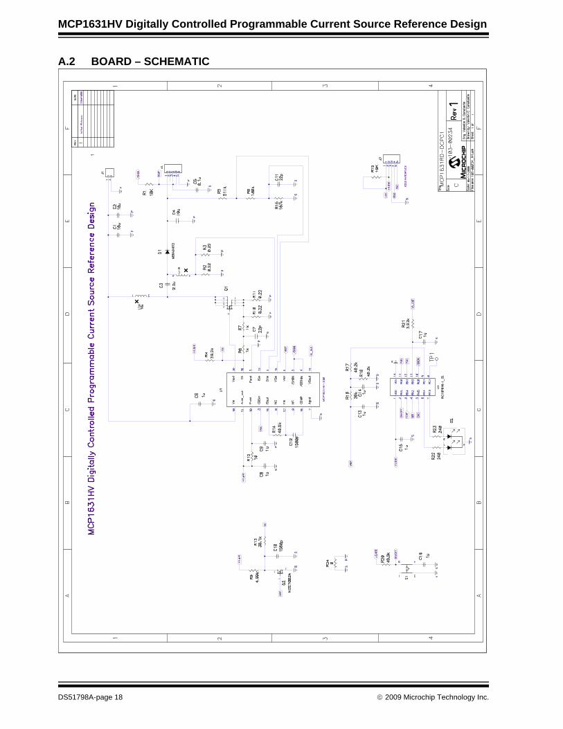
A.2 BOARD – SCHEMATIC
M
3
1
2
5
8 3
4
67
12
DS51798A-page 18 © 2009 Microchip Technology Inc.
Schematic and Layouts
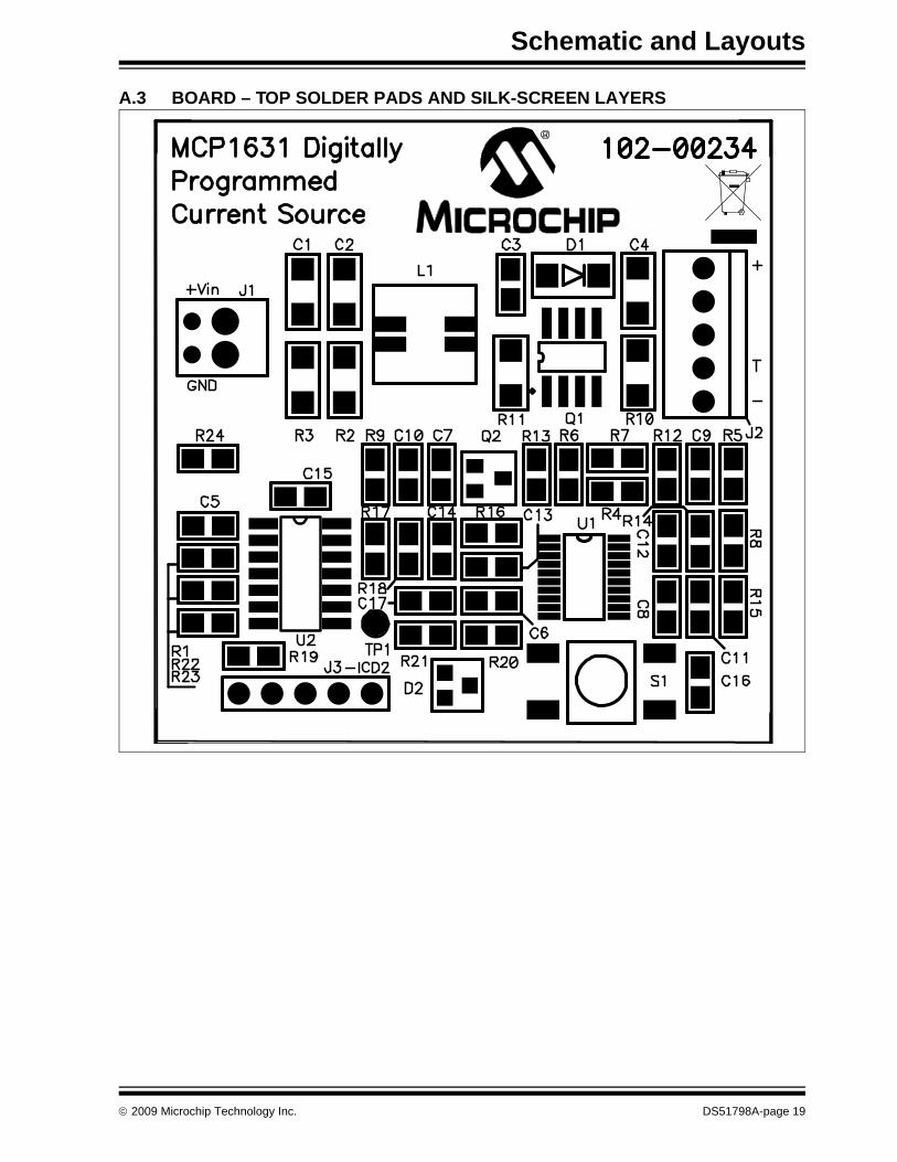
A.3 BOARD – TOP SOLDER PADS AND SILK-SCREEN LAYERS
© 2009 Microchip Technology Inc. DS51798A-page 19
MCP1631HV Digitally Controlled Programmable Current Source Reference Design
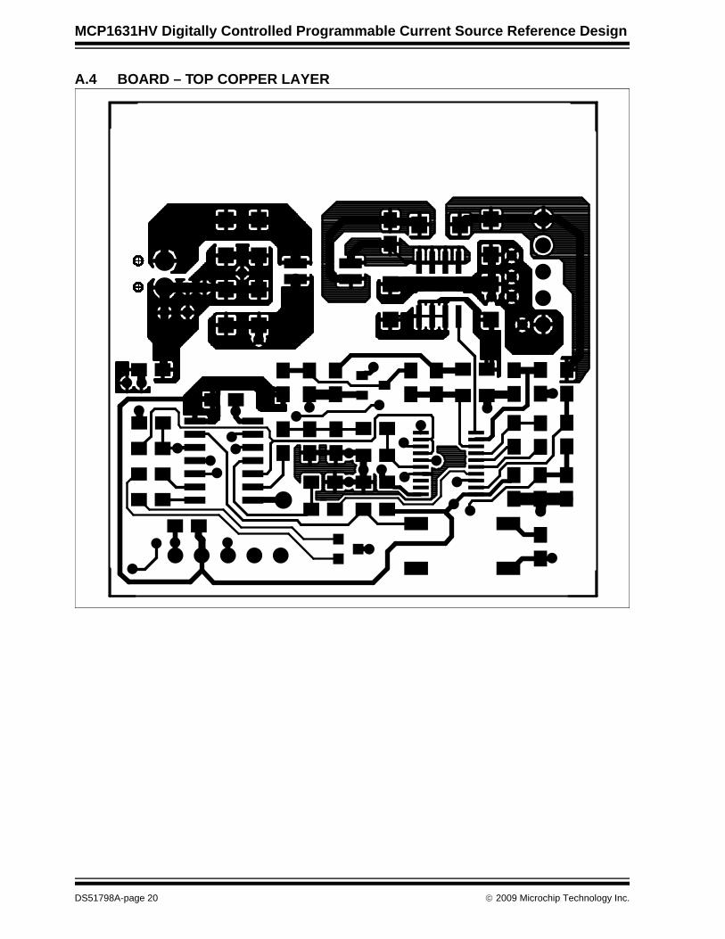
A.4 BOARD – TOP COPPER LAYER
DS51798A-page 20 © 2009 Microchip Technology Inc.
Schematic and Layouts
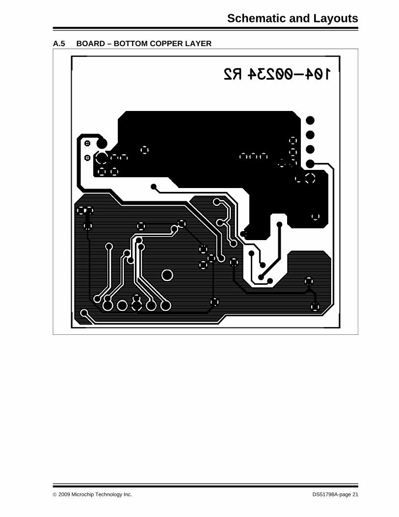
A.5 BOARD – BOTTOM COPPER LAYER
© 2009 Microchip Technology Inc. DS51798A-page 21

MCP1631HV Digitally Controlled Programmable Current Source Reference Design
NOTES:
DS51798A-page 22 © 2009 Microchip Technology Inc.
MCP1631HV DIGITALLY CONTROLLEDPROGRAMMABLE CURRENT SOURCE
REFERENCE DESIGN
Appendix B. Bill Of Materials (BOM)
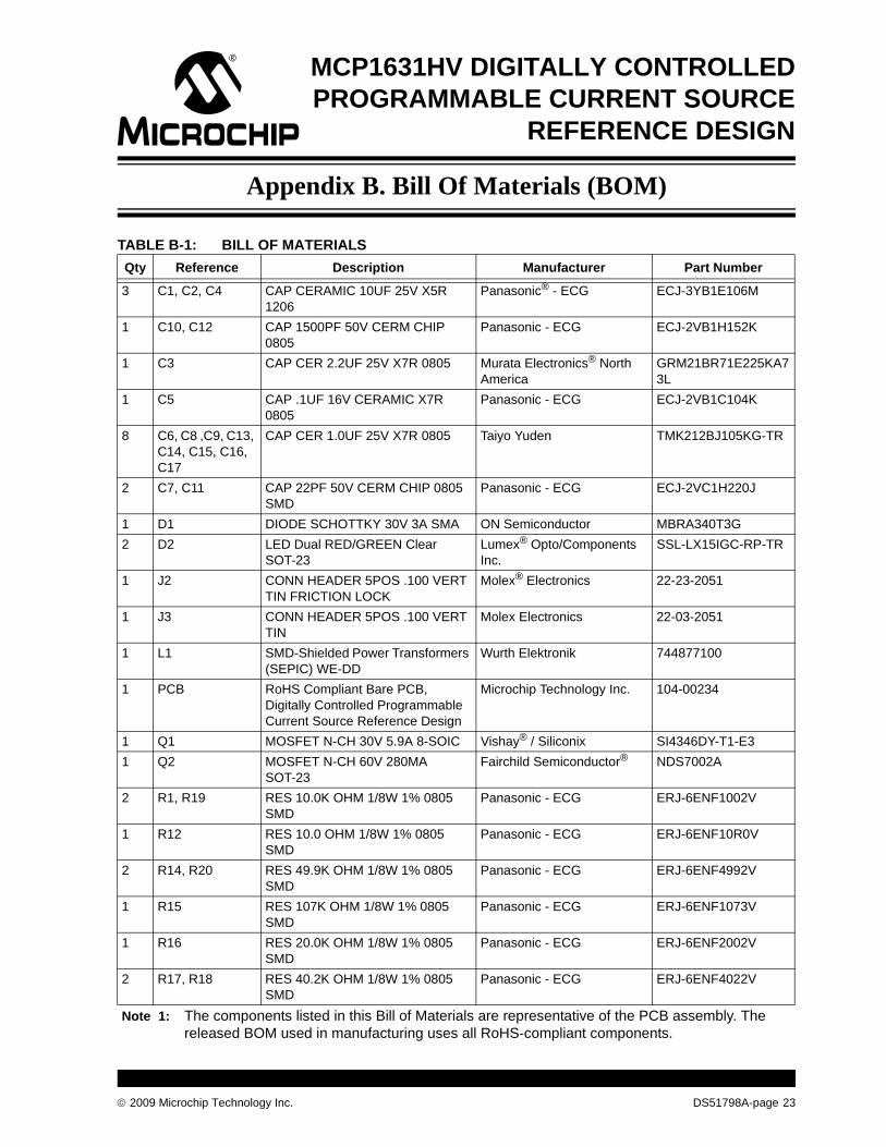
TABLE B-1: BILL OF MATERIALSQty Reference Description Manufacturer Part Number
3 C1, C2, C4 CAP CERAMIC 10UF 25V X5R 1206
Panasonic® - ECG ECJ-3YB1E106M
1 C10, C12 CAP 1500PF 50V CERM CHIP 0805
Panasonic - ECG ECJ-2VB1H152K
1 C3 CAP CER 2.2UF 25V X7R 0805 Murata Electronics® North America
GRM21BR71E225KA73L
1 C5 CAP .1UF 16V CERAMIC X7R 0805
Panasonic - ECG ECJ-2VB1C104K
8 C6, C8 ,C9, C13, C14, C15, C16, C17
CAP CER 1.0UF 25V X7R 0805 Taiyo Yuden TMK212BJ105KG-TR
2 C7, C11 CAP 22PF 50V CERM CHIP 0805 SMD
Panasonic - ECG ECJ-2VC1H220J
1 D1 DIODE SCHOTTKY 30V 3A SMA ON Semiconductor MBRA340T3G2 D2 LED Dual RED/GREEN Clear
SOT-23Lumex® Opto/Components Inc.
SSL-LX15IGC-RP-TR
1 J2 CONN HEADER 5POS .100 VERT TIN FRICTION LOCK
Molex® Electronics 22-23-2051
1 J3 CONN HEADER 5POS .100 VERT TIN
Molex Electronics 22-03-2051
1 L1 SMD-Shielded Power Transformers (SEPIC) WE-DD
Wurth Elektronik 744877100
1 PCB RoHS Compliant Bare PCB, Digitally Controlled Programmable Current Source Reference Design
Microchip Technology Inc. 104-00234
1 Q1 MOSFET N-CH 30V 5.9A 8-SOIC Vishay® / Siliconix SI4346DY-T1-E31 Q2 MOSFET N-CH 60V 280MA
SOT-23Fairchild Semiconductor® NDS7002A
2 R1, R19 RES 10.0K OHM 1/8W 1% 0805 SMD
Panasonic - ECG ERJ-6ENF1002V
1 R12 RES 10.0 OHM 1/8W 1% 0805 SMD
Panasonic - ECG ERJ-6ENF10R0V
2 R14, R20 RES 49.9K OHM 1/8W 1% 0805 SMD
Panasonic - ECG ERJ-6ENF4992V
1 R15 RES 107K OHM 1/8W 1% 0805 SMD
Panasonic - ECG ERJ-6ENF1073V
1 R16 RES 20.0K OHM 1/8W 1% 0805 SMD
Panasonic - ECG ERJ-6ENF2002V
2 R17, R18 RES 40.2K OHM 1/8W 1% 0805 SMD
Panasonic - ECG ERJ-6ENF4022V
Note 1: The components listed in this Bill of Materials are representative of the PCB assembly. The released BOM used in manufacturing uses all RoHS-compliant components.
© 2009 Microchip Technology Inc. DS51798A-page 23
MCP1631HV Digitally Controlled Programmable Current Source Reference Design
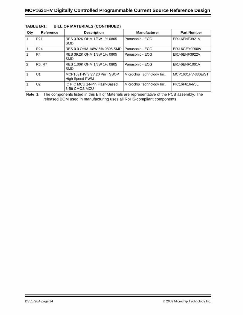
1 R21 RES 3.92K OHM 1/8W 1% 0805 SMD
Panasonic - ECG ERJ-6ENF3921V
1 R24 RES 0.0 OHM 1/8W 5% 0805 SMD Panasonic - ECG ERJ-6GEY0R00V1 R4 RES 39.2K OHM 1/8W 1% 0805
SMDPanasonic - ECG ERJ-6ENF3922V
2 R6, R7 RES 1.00K OHM 1/8W 1% 0805 SMD
Panasonic - ECG ERJ-6ENF1001V
1 U1 MCP1631HV 3.3V 20 Pin TSSOP High Speed PWM
Microchip Technology Inc. MCP1631HV-330E/ST
1 U2 IC PIC MCU 14-Pin Flash-Based, 8-Bit CMOS MCU
Microchip Technology Inc. PIC16F616-I/SL
TABLE B-1: BILL OF MATERIALS (CONTINUED)Qty Reference Description Manufacturer Part Number
Note 1: The components listed in this Bill of Materials are representative of the PCB assembly. The released BOM used in manufacturing uses all RoHS-compliant components.
DS51798A-page 24 © 2009 Microchip Technology Inc.
MCP1631HV DIGITALLY CONTROLLEDPROGRAMMABLE CURRENT SOURCE
REFERENCE DESIGN
Appendix C. Demo Board Firmware
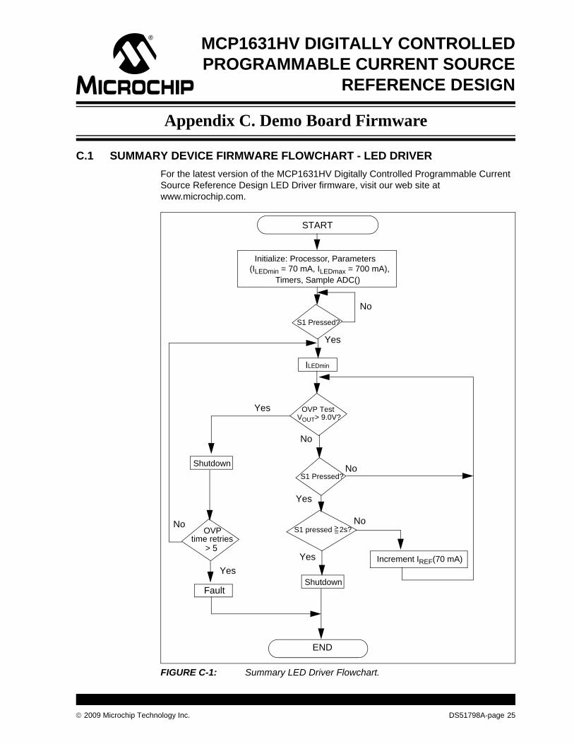
C.1 SUMMARY DEVICE FIRMWARE FLOWCHART - LED DRIVERFor the latest version of the MCP1631HV Digitally Controlled Programmable Current Source Reference Design LED Driver firmware, visit our web site at www.microchip.com.
FIGURE C-1: Summary LED Driver Flowchart.
START
Initialize: Processor, Parameters
No
Yes
END
OVP Test VOUT> 9.0V?
No
Fault
OVPtime retries
> 5
Yes
(ILEDmin = 70 mA, ILEDmax = 700 mA), Timers, Sample ADC()
Shutdown
Shutdown
S1 Pressed?
Yes
No
Increment IREF(70 mA)
S1 pressed 2s?>=
Yes
No
S1 Pressed?
No
Yes
ILEDmin
© 2009 Microchip Technology Inc. DS51798A-page 25
Demo Board Firmware
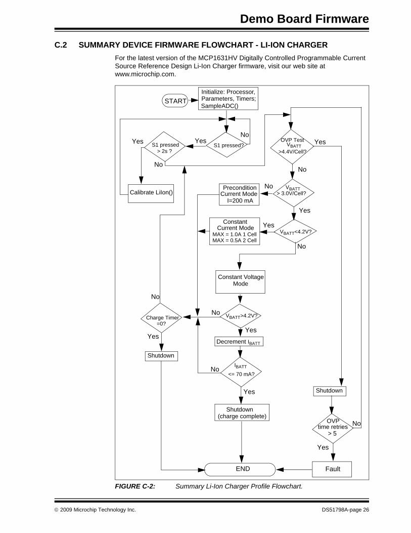
C.2 SUMMARY DEVICE FIRMWARE FLOWCHART - LI-ION CHARGERFor the latest version of the MCP1631HV Digitally Controlled Programmable Current Source Reference Design Li-Ion Charger firmware, visit our web site at www.microchip.com.
FIGURE C-2: Summary Li-Ion Charger Profile Flowchart.
Initialize: Processor,
END
VBATT >4.4V/Cell?
Yes
No
MAX = 1.0A 1 CellMAX = 0.5A 2 Cell
IBATT
<= 70 mA?
Yes
No
Fault
VBATT > 3.0V/Cell?
Parameters, Timers; SampleADC()
Calibrate LiIon()
YesNo
> 2s ?
VBATT<4.2V?Yes
ConstantCurrent Mode
Constant Voltage
Shutdown(charge complete)
Shutdown
OVPtime retries
> 5
Yes
Yes
NoPreconditionCurrent Mode I=200 mA
No
No
START
Mode
S1 pressed OVP Test
S1 pressed?Yes
No
VBATT>4.2V?
Decrement IBATT
Shutdown
Charge Timer=0?
Yes
No
Yes
No
© 2009 Microchip Technology Inc. DS51798A-page 26
Demo Board Firmware
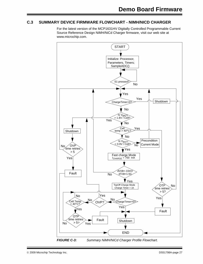
C.3 SUMMARY DEVICE FIRMWARE FLOWCHART - NIMH/NICD CHARGERFor the latest version of the MCP1631HV Digitally Controlled Programmable Current Source Reference Design NiMH/NiCd Charger firmware, visit our web site at www.microchip.com.
FIGURE C-3: Summary NiMH/NiCd Charger Profile Flowchart.
START
Is VBATT
Parameters, Timers;
NoYes
Fast charge ModeICHARGE = 700 mA
dV/dt<-10mVdT/dt>1.5C
Yes TopOff Charge Mode
> 0.9V / Cell?PreconditionCurrent Mode
Yes
No
Charge Timer = 1h
END
Fault
Initialize: Processor,
SampleADC()
Shutdown
S1 pressed?No
Yes
ChargeTimer=0? ShutdownYes
No
No
Shutdown
OVPtime retries
> 5
Yes
No
ChargeTimer=0?No
Yes
Is VBATT > 1.8V / Cell?
Celltemp > 40oC?
No
OTPtime retries
> 5?
Yes
No
Fault
Cell Temp> 40°C?
Yes
No
Yes
OVP?
OTPtime retries
> 5? Yes
No
FaultNo
Yes
© 2009 Microchip Technology Inc. DS51798A-page 27
DS51798A-page 28 © 2009 Microchip Technology Inc.
AMERICASCorporate Office2355 West Chandler Blvd.Chandler, AZ 85224-6199Tel: 480-792-7200 Fax: 480-792-7277Technical Support: http://support.microchip.comWeb Address: www.microchip.comAtlantaDuluth, GA Tel: 678-957-9614 Fax: 678-957-1455BostonWestborough, MA Tel: 774-760-0087 Fax: 774-760-0088ChicagoItasca, IL Tel: 630-285-0071 Fax: 630-285-0075ClevelandIndependence, OH Tel: 216-447-0464 Fax: 216-447-0643DallasAddison, TX Tel: 972-818-7423 Fax: 972-818-2924DetroitFarmington Hills, MI Tel: 248-538-2250Fax: 248-538-2260KokomoKokomo, IN Tel: 765-864-8360Fax: 765-864-8387Los AngelesMission Viejo, CA Tel: 949-462-9523 Fax: 949-462-9608Santa ClaraSanta Clara, CA Tel: 408-961-6444Fax: 408-961-6445TorontoMississauga, Ontario, CanadaTel: 905-673-0699 Fax: 905-673-6509
ASIA/PACIFICAsia Pacific OfficeSuites 3707-14, 37th FloorTower 6, The GatewayHarbour City, KowloonHong KongTel: 852-2401-1200Fax: 852-2401-3431Australia - SydneyTel: 61-2-9868-6733Fax: 61-2-9868-6755China - BeijingTel: 86-10-8528-2100 Fax: 86-10-8528-2104China - ChengduTel: 86-28-8665-5511Fax: 86-28-8665-7889China - Hong Kong SARTel: 852-2401-1200 Fax: 852-2401-3431China - NanjingTel: 86-25-8473-2460Fax: 86-25-8473-2470China - QingdaoTel: 86-532-8502-7355Fax: 86-532-8502-7205China - ShanghaiTel: 86-21-5407-5533 Fax: 86-21-5407-5066China - ShenyangTel: 86-24-2334-2829Fax: 86-24-2334-2393China - ShenzhenTel: 86-755-8203-2660 Fax: 86-755-8203-1760China - WuhanTel: 86-27-5980-5300Fax: 86-27-5980-5118China - XiamenTel: 86-592-2388138 Fax: 86-592-2388130China - XianTel: 86-29-8833-7252Fax: 86-29-8833-7256China - ZhuhaiTel: 86-756-3210040 Fax: 86-756-3210049
ASIA/PACIFICIndia - BangaloreTel: 91-80-3090-4444 Fax: 91-80-3090-4080India - New DelhiTel: 91-11-4160-8631Fax: 91-11-4160-8632India - PuneTel: 91-20-2566-1512Fax: 91-20-2566-1513Japan - YokohamaTel: 81-45-471- 6166 Fax: 81-45-471-6122Korea - DaeguTel: 82-53-744-4301Fax: 82-53-744-4302Korea - SeoulTel: 82-2-554-7200Fax: 82-2-558-5932 or 82-2-558-5934Malaysia - Kuala LumpurTel: 60-3-6201-9857Fax: 60-3-6201-9859Malaysia - PenangTel: 60-4-227-8870Fax: 60-4-227-4068Philippines - ManilaTel: 63-2-634-9065Fax: 63-2-634-9069SingaporeTel: 65-6334-8870Fax: 65-6334-8850Taiwan - Hsin ChuTel: 886-3-6578-300Fax: 886-3-6578-370Taiwan - KaohsiungTel: 886-7-536-4818Fax: 886-7-536-4803Taiwan - TaipeiTel: 886-2-2500-6610 Fax: 886-2-2508-0102Thailand - BangkokTel: 66-2-694-1351Fax: 66-2-694-1350
EUROPEAustria - WelsTel: 43-7242-2244-39Fax: 43-7242-2244-393Denmark - CopenhagenTel: 45-4450-2828 Fax: 45-4485-2829France - ParisTel: 33-1-69-53-63-20 Fax: 33-1-69-30-90-79Germany - MunichTel: 49-89-627-144-0 Fax: 49-89-627-144-44Italy - Milan Tel: 39-0331-742611 Fax: 39-0331-466781Netherlands - DrunenTel: 31-416-690399 Fax: 31-416-690340Spain - MadridTel: 34-91-708-08-90Fax: 34-91-708-08-91UK - WokinghamTel: 44-118-921-5869Fax: 44-118-921-5820
WORLDWIDE SALES AND SERVICE
03/26/09