Embed Size (px)
Citation preview

mCMSSIFIED 1
ARH-MA-119
2^2-S E¥AP0R4TOR-CRySTALLIZER IIFOmmTIOH PIAKUAL
R. R. Henderson Waste Handling and Plutonium F in i sh ing Process Engineering
Operat ions Technica l Support Department
September 1975
Operated f o r the Energy Research and Development Adminis t ra t ion by A t l a n t i c R ich f i e ld Hanford Company under Contract E(45- l ) -2130
mCMSSIFIED
Hus teport was psepmed as an actoont c-t work spoiiisoEed h\ the L'liited States (>o^emment Neither the I'nited States nor the I'mted States Department ot Fneigv, nm anv of Aeu empkness, nur aii> of then tOsUratt"S's subi.ofitras,EoJS, cr their employees flakes am w^aiiantv, e\press 01 iinphed, or assumes aiiv legal hahihty or responsibihtv for tiie accuiaiV. completeness o* usefulness ot any mionmtum. apparatus, prod^tt or psot*fss di'^closed. Of represents that its u ^ v^tmld not mfdsioa pm^tel> owned nghts
DISCLAIMER
This report was prepared as an account of work sponsored by an agency of the United States Government. Neither the United States Government nor any agency Thereof, nor any of their employees, makes any warranty, express or implied, or assumes any legal liability or responsibility for the accuracy, completeness, or usefulness of any information, apparatus, product, or process disclosed, or represents that its use would not infringe privately owned rights. Reference herein to any specific commercial product, process, or service by trade name, trademark, manufacturer, or otherwise does not necessarily constitute or imply its endorsement, recommendation, or favoring by the United States Government or any agency thereof. The views and opinions of authors expressed herein do not necessarily state or reflect those of the United States Government or any agency thereof.

DISCLAIMER Portions of this document may be illegible in electronic image products. Images are produced from the best available original document.

2 ARH-
TABEE OF COITENTS
Page
INTRODUCTIOH - — - » - » — . — — — — — — — — — — . — — » — — — — k
PROCESS DESCRIPTIOl — — — — — . — » _ — » — — — — ™ _ — — — h
FACILITIES DESCRIPTIOl - — — « — » — - — — . — ^ — . — — — — » — . - 9
General -——-™_^_^_-___»._-._—._____«_____________«____ 9
Reboiler (E-A-l) — — . — . — — — » — » - _ - — -__-._-™™____ n
Evaporator (C-A-l) - — » — — - . — — » — — - » » . __»»„_._„__ 12
Recirculation Pump (P-B-l) ™ — — — ^ _ — — . — — — — » _ — - - ik
Bottoms Pump (P-B-2) — — — — » - — — — - . — — — - . — » — — lii.
Primary Condenser (E-C-l) — — . _ — — — . — — — — — _ > _ _ _ _ _ 16
Inter-Condenser ( E - C - 2 ) - » — — — - - — - » _ , 16
After Condenser ( E - C ~ 3 ) — ._-__-„_ — __>_ 17
Vessel Ventilation System — -—• -——•—.-——- 18
Building Ventilation — — ™ — .___„___„__„ 19 Seirice Area ------- .—.—-—.— . .—.-—,_-__ 20 Process Area »—-™~-.».-——_____-_->_ _..«—„«_«_ 2I Operating Area —----—,__>____.___„______,___«„_-_ 22
Condensate Tank (TK-C-lOO) -——.———.—.»._———™— 22
Condensate Pump (P-C-lOO) - . — — — — » . — — — — — — » - 23
Condensate F i l t e r (P-C-l) ——• «_>-.-.-.«_»>_—_»-»—._— 23
Ion Exchange Column (iX-D-l) --—_—.———. _„„_.„__ 23
Eluant Tank (TK-E-101) ^ — — — — — — — — — - ™ — — — 26
Eluant Pump (P-E-lOl) —™™-.™»-.———™-™——.-.»——— 26
Anti-Foam Tank (TK-E-102) —— - » - » — _ — _ . - . _ ™ — 26
Anti-Foam Bmp (P-E-102) -«—»»———.——»—-—»- 2T

3 ARH-M-119
TABM OF CdfTEWTS CONTIHUED
Page
Decontamination Tank (TK-E--104) — ™ — — ~ — - ^ — — — . — ^ 27
Decontamination Pump (P-E-104) - — ,»»—.____«>____- 27
Pump Room Sump .-»—™——-.—___«____^».___»______..^_ 27
Steam Condensate Radiation Monitoring, Proportional Sampling, and Diversion System (R-C-l) — — - « — — — — - 28
Cooling Water Radiation Monitoring and Proportional Psampling System (R-C-2) - . — — » . — — — , — - 29
Process Condensate Radiation Monitoring, Proportional
Sampling, and Diversion System (R-C-.3) - — ™ — — — — 30
Air Sample Radiation Monitoring Systems --»_-—_-«-—-- 31
Slurry Sampler ——~-.-.—__«__>____-_».___»._.^ ____„___ 33 Process Air Supply System — » — — — — — — — ~ — — . ™ - — 33
Overhead Crane -——-.—--_—-.—____-.™__-_™_™_._.^ ___» 35
Interlocks -—-—-.>___..-.—.—.—--—,_-.--.-——.-.»-_--——_- 35 Number One -———.—>__._.»__„._„«_„«»_.„»___ 35 lumber Two « — — . » — — — . « - » . — — — » — — » » ™ - 37 lumber Three » — - — . . ^ — — » - - — » . — . — — ™ — — 38 Number Four - ™ — — — — - — - > _ — „ „ « _ _ - _ . . _ _ - _ 39 Number Five — - - — - - — — . - « — _>„>._..«,.«» kO lumber Six — ™ — • ,__»_.___>____»»______»__„ kO lumber Seven —.»___»._«»._____—.—____—_—-__ kl Number Eight » — — » — — - » — — — » « — » — — — k2 Number Nine — . ™ — — ™ » — . — „ » _ _ _ _ » »____—_ k3 Number Ten - » — — — . — — — — - ™ — — — — » — — 43 N\imber Eleven —-.—-™-—————"-——"-—--— hk Number Twelve » — — — — — — - » — — — — — — 44 Number Thi r teen —.__-.»»™™—._— ™_____>_™„__ 45
APPfflDIX —————.—™———._-- .——.—^——»—_—™—»,^ 1+7
REPEEENCES — — — — — — — , ___._>_«„_„___.„__.__ kj
ACKNOWLEDGMENTS ^ — — » — — _ — » — — — — — — — — ™ — k8
LIST OF FIGURES - » — ^ - ™ - » ™ — » . ~ ™ » ^ - — — — — ^ - » - » - ^ — 49

h Affl-MA-119
242-S EVAPORATOR-CRYSTALLIZER IiP0H4ATI0N MANUAL
INTRODUCTION
Low heat wastes, which contain relatively small quantities of
fission products, are stored in the Hanford nonboiling waste tank
farms. A major portion of the Waste Management Program at Hanford
is concerned with the immobilization of these radionuclide-bearing
waste solutions. The 242-S Evaporator-Ciystallizer is utilized to
reduce the mobility of aqueous waste solutions which do not self-
boil. The evaporator operates under a vacuum, employing evaporative
concentration with subsequent crystallization and precipitation of
salt crystals. This process allows for greater sludge-slurry con
centrations, thereby reducing the number of underground storage
tanks required.
This manual describes the process, facilities, and equipment
associated with the 242-S Evaporator-Crystallizer. Figures referred
to in the text can be found in the Appendix.
PROCESS DESCBIPTION
The 242-S evaporator process employs a conventional forced-
circulation, vacuum evaporation system to concentrate radioactive
waste solutions. Main process components of the evaporator-
crystallizer system located in the 242-S building are the reboiler,
vapor-liquid separator, recirculation pximp and pipe loop, slurry
product pump, primary condenser, jet vacuum system, condensate

5 ARH-MA-119
collection tank, and ion exchange column. (See Fig. 1 for an over
all view of the systemj flow rates, capacities, and other informa
tion shown on this flow diagram are design data only.)
The evaporator system receives a feed blend from the 102-S
tank which consists of unprocessed waste and recycled supeitiatant
which has been decanted from the bottoms settling tanks. The feed
is pumped into the recirculation line on the upstream side of the
reboiler (see Fig. 2) at a rate controlled to maintain a constant
crystallizer weight factor. As the feed enters the recirculation
line, it blends with the main process sluriy stream which flows to
the reboiler. In the reboiler, the mixture is heated slightly to
a specified operating temperature, normally I30 °F to I70 F, by
using 3 to 10 psig steam. The low pressure steam provides adequate
heat transfer, and the resulting low temperature differential helps
minimize scale formation on the heat transfer surfaces.
The heated slurry stream is discharged from the reboiler to
the vapor-liquid separator, which is maintained at approximately 0.8
psia. Under this reduced pressure, a fraction of the water in the
salt slurry concentrate flashes to steam and is drawn through two
wire mesh deentrainer pads into a 42-inch vapor line leading to the
primary condenser. As evaporation takes place in the separator ves
sel, further super-saturation occurs in the salt liquor sluriy which
creates new salt crystal nuclei and promotes growth of existing
crystals in the slurry liquor. After the process slurry has remained

6 ARH-14A-119
in the vapor-liquid separator approximately one and one-half minutes,
it flows to the recirculation pump suction via the separator vessel
drop-out leg and lower recirculation line. The recirculation pump
discharges the slurry back to the ireboiler via the upper recircu
lation line, thus completing the process circuit. 0!he process is
continuous with typical stream rates of 90 to 110 gpm for the feed
from 102-S, 30 to 50 gpm for the condensate, and 50 to 70 gpm for
the slurry discharge.
The recirculation pump (P-B-l) moves waste at high velocities
through the reboiler in order to:
1. improve the heat transfer coefficient,
2. reduce fouling of heat transfer surfaces,
3. keep solids in suspension, and
h. permit transfer of large quantities of heat with only a small change in temperature of the solution being heated. Thus, the static pressure of the solution above the reboiler is sufficient to suppress the boiling point such that the solution will not boil in the tubes. Boiling occurs only near or at the liquid surface in the vapor-liquid separator.
When the process solution has been concentrated to the point
where it contains 20 to 30 percent solids or the nonnal operating
temperature has been reached, a small fraction is withdrawn from
the upper recirculation line and is pumped by the slurry pump to
underground storage tanks. In the storage tanks, the sluriy is
allowed to settle into a salt cake layer and a supernatant liquor
layer. The supernatant layer is decanted and pumped to the feed

7 ARH-MA-119
tank (102-S) where it is mixed with other waste feed stocks to
maintain the solids concenti'ation in the evaporator feed stream
at a desired level.
Because of the high concentration of solids in the slurry,
pluggage of the transfer lines from the evaporator to the tank
farm settling tanks may occur due to solids settling. The slurry
puii5> (P-B-2) is designed for high pressures so that the slurry
can be transferred at high velocities to help alleviate this
problem.
Vapors removed from the vapor-liquid separator are condensed
in the primary condenser, which then drains to the condensate
collection tank (C-lOO) (see Pig. 3). An in-line pump (P-C-lOO)
moves the process condensate from the tank through a filter
(P-C-l) to remove solids, and downflow through the ion exchange
column (IX-D-I) to reduce the final cesium and strontium concen
trations (see Fig. h)^ The condensate exits from the column, flows
through a seal loop that maintains a flooded bed, and is discharged
to the 216-S-25 crib after passing through an in-line filter which
collects any resin that escapes the column. A small portion of
the condensate flow is routed from the discharge line through the
R-C-3 proportional sampler and radiation monitor and is returned
to tank C-100.
Regeneration of the ion exchange resin bed is required when
the bed becomes saturated with cesium and strontium, as indicated

8 ARH-MA-119
by the process condensate discharge samples (RC3), or iresin samples
obtained through the resin addition port. Regeneration is accomp
lished by pumping hot, concentrated sodium nitrate solution from
TK-E-101 upflow through the column, followed by a water-wash to
remove the eluant solution and accumulated resin fines.
Resin particles in the ion exchange column may break down due
to the effects of radiation, abrasion, and the caustic nature of
the process condensate. Fines produced by this breakdown may cause
partial pluggage of the resin bed and restrict the flow of conden
sate to the crib, as well as increase the column dp. The column may
be backflushed to remove the fines by flushing upflow with process
condensate. If the cesium loading capacity of the resin becomes too
low, the resin is replaced.
Vacuum in the vapor-liquid separator is maintained at approxi
mately 0.8 psia via the primary condenser and process vapor line by
a two-stage jet eductor system. Motive steam fixsm the primary jet
and the secondaiy jet discharges, respectively, to the inter-
condenser and after condenser. Both condensers drain to the
process condensate collection tank, while non-condensibles are
filtered and discharged to the atmosphere via the vessel vent
system (see Fig. 4).
There are three streams leaving the building that are dis
charged to the ground! the process condensate discharged to the
216-S-25 crib, the steam condensate from the reboiler discharged
to the 216-U-lO pond, and the cooling water from the condensers

9 ARH-MA-119
also discharged to the pond. These three streams are provided
with continuous proportional sampling systems including radia
tion monitoring equipment.
The R-C-1 radiation monitor and proportional sampler
monitors the steam condensate from the reboiler. Its diversion
valve can route the condensate to the 103-S tank if it does not
meet specifications. The R-C-2 system monitors the cooling water
stream. It is not equipped with a diversion valve since the
potential for radionuclide contamination of this stream is very
low. A plant shutdown would be required if it should become
contaminated. Finally, the process condensate is monitored by
the R-C-3 system, which can divert the condensate flow to the
C-100 tank to be recycled via the I03-S tank as feed for the
evaporator.
FACILITIES DESCRIPTION
General
The 242-S building is located north of the 241-S and 24l-
SX tank farms in the 200 West Area of the Hanford reservation
(see Fig, 8). It consists of the following:
storage and maintenance roomj
lunch roomi
lavatories and change roomj
clean and soiled clothes storage;
control room, containing the control panelsj

10 ARH-MA-119
aqueous make-up (AMU) room, containing the process air supply system and the anti-foam, decontamination, and eluant tanksj
condenser room, containing the primary condenser, jet vacuum system, condensate collection tank, and vessel ventilation systemi
loading roomj
load-out and hot equipment storage, which contains two sumps that drain to the pump room sumpj
pump room, which has removable cover blocks and contains the slurry and recirculation pumps as well as the pump room sumpj
evaporator room, which contains the vapor-liquid separator and the reboilerj
heating, ventilation and air conditioning (HVAC) room, located above the AMU room and containing the steam supply system, building ventilation system, and raw water filters;
ion exchange column room.
See Figures 9 and 10 for relative locations.
Steam and raw water are both supplied to the 242-S building
from the power plant in the 200 West Area.
Descriptions of the important facilities in the evaporator
system are included in the sections following. Drawings, flow
diagrams and construction specifications used for reference are
listed in the Appendix; their reference numbers are listed prior
to each individual section.

11 ARH-MA-119
Reboiler (E-A-l) Ref. 2, p. 92| 12; 13
Slurry is heated in the reboiler prior to entering the
vapor-liquid separator. The 2«5 x 10* Btu/hr duty reboiler is
a vertical tube unit with steam shell side and process solution
tube side with standard operating parameters of 0.8 psia pres
sure and 130 Op to 170 °P temperature. It consists of 364 tubes,
each having a l4'-l/8" length and I-1/2" outside diameter (OD),
arranged with a I-7/8" triangular pitch. The tubes are encased
by a 40-I/2" OD, 15' long stainless steel shell. Temperature
elements TE-CAl-2 and Bil-EAl-1 are located respectively at the
reboiler inlet and outlet. It has three equally spaced baffles,
as well as an impingement baffle which foims a vapor belt at
the steam inlet (see Pig. 11).
The steam required for the evaporation process is supplied
to the 242-S building from the 200 W Area high pressure steam
loop, and is reduced from 225 pounds to 90 pounds outside the
building. The 90-pound steam is reduced to 10-pound steam which
passes through a desuperheater to reduce the temperature and
ensure saturation by the addition of filtered raw water before
it is used in the reboiler. The 90-pound steam is also routed
to the desuperheater to atomize the filtered water. The carbon
steel desuperheater, designed to handle steam at 2.7 x 10^ Ib/hr,
is the steam ejector, atomizing type.
Steam condensate normally goes to the U Plant pond (216-U-IO)

12 ARH-M-119
but can be diverted to 103-S if a leak should occur in the reboiler.
The steam condensate line is continuously monitored with radiation
reading instruments (RE-EAl-l) to detect such a leak, as is the
steam condensate in the condensate sampler (RE-RCl-l). Readings
above a set level at either of these instruments will automatically
divert the steam condensate from the pond to tank 103-S.
Evaporator (C-A-l) Ref. l4; 15; 21; 22
Process solution from the reboiler discharges to the vapor-
liquid separator via the upper recirculation line. The separator
consists of two basic sections (see Fig. 12), The lower (liquid)
section is a l4-foot OD stainless steel shell with a 22,500-gallon
to 25,OOO-gallon normal operating capacity (including recirculation
loop and reboiler). The vapor section is an 11'-6" OD stainless
steel shell, making the overall height of the separator 4l'-l 3/ "«
Total volume is 35^600 gallons when filled to the top of the vapor
section. Steam flows out of the separator through a 42-inch vapor
line at the top, and concentrated slurry exits via the vessel's
28-inch recirculation line.
The top section of the evaporator contains two deentrainer
pads approximately 3'-^ I/2" apart. The lower pad is four inches
thick, and the upper one is six inches thick; both are 0.011-inch
wire mesh packed to a density of 12 lb/ft3. A total of sixteen
spray nozzles, four on top and four on bottom of each pad, are
equally spaced and alternated for even distribution of water to
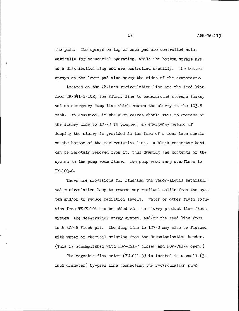
13 ABH-MA-119
the pads. The sprays on top of each pad are controlled auto
matically for sequential operation, while the bottom sprays are
on a distribution ring and are controlled manually. The bottom
sprays on the lower pad also spray the sides of the evaporator.
Located on the 28-inch recirculation line are the feed line
from TK-241-S-102, the slurry line to underground storage tanks,
and an emergency dump line which routes the slurry to the 103-S
tank. In addition, if the dump valves should fail to operate or
the slurry line to 103-S is plugged, an emergency method of
dumping the sluriy is provided in the fonn of a four-inch nozzle
on the bottom of the recirculation line. A blank connector head
can be remotely removed from it, thus dumping the contents of the
system to the pump room floor. The pump room sump overflows to
TK-I03-S.
There are provisions for flushing the vapor-liquid separator
and recirculation loop to remove any residual solids from the sys
tem and/or to reduce radiation levels. Water or other flush solu
tion from TK-E-104 can be added via the slurry product line flush
system, the deentrainer spray system, and/or the feed line from
tank 102-S flush pit. The dump line to 103-S may also be flushed
with water or chemical solution from the decontamination header.
(This is accomplished with BDV-CAl-7 closed and POV-CAl-9 open.)
The magnetic flow meter (FM-CAI-3) is located in a small (3-
inch diameter) by-pass line connecting the recirculation pump

1^ ARH-MA-119
discharge with the pump suction. The flow measured through this
line is indirectly a measure of the flow through the reboiler.
A radiation monitor (RE-CAl-l) is installed in the 42-inch
vapor line leading to the primary condenser. Normally, entrained
liquid is removed from the vapor and does not reach the conden
ser. However, the line is monitored due to the potential for
foaming or bumping of contaminated liquid out of the evaporator.
Other instrumentation includes expansion bellows in the 42-
inch vapor line, and two dip tube assemblies (DTA) in the evapo
rator. One DTA (CA-1-1 and CA-1-2) measures weight factor/specific
gravity (WP/SpG); the other HEA (CA-1-3) measures W only. Both
consist of 1/2-inch schedule 40 stainless pipe dip tubes. Also
located in the evaporator itself is a temperature element, TE-CAl-1.
Recirculation Pump (P-B-l) Ref. 1
The stainless steel recirculation pump discharges slurry
back to the reboiler via the upper recirculation line. The
28-inch vertical propeller pxanp has a 14,000 gpm output with a
12.55-foot total dynamic head and is designed to handle waste
containing up to 65 percent solids by volume.
Bottoms Pump (P-B-2) Ref. 4; 30
The slurry pump has a total dynamic head of 5OO feet and is
constructed of 30^ L stainless steel. It is a single stage,
horizontal, centrifugal pump driven by a variable speed motor

15 ARH-m-119
with a 50 to 100 gpm normal flow. It pumps concentrated slurry
from the recirculation line to the tank farm settling tanks.
Both the recirculation pump and the slurry pump are equipped
with a dual seal with high pressure water introduced between the
seals to prevent process solution from leaking out of the system.
Because the water pressure is maintained at a value in excess of
the process pressure at the seal, water can leak either into the
system or out of the pump, but the process solution cannot leak
out of the pump as long as the required water pressure is main
tained between the seals.
Slurry transfer to the settling tanks is monitored with a
magnetic flow meter (FM-rAl-4). A decrease in flow below a
specified value will automatically shut the pump down and initiate
a line flush with water. A sight glass is installed in a by-pass
line for the purpose of checking the solids content of the slurry
stream, although this method is not used currently.
The slurry transfer line can be flushed in either direction
using manual controls. Flushing involves positioning POV-CAl-2
and P0V-CA1-2A for the operation—'either to the evaporator or to
the tank farm—and flushing with water or a chemical solution from
the decontamination header.

16 ARH-m-119
Primary Condenser (E-C-l) Ref. 7; 8; 9; 10; 11
The vapors removed from the evaporator are condensed in the
primary condenser. The 2.2 x loT Btu/hr duty, carbon steel con
denser measures 17'-5 7/8" long and has an 85" inside diameter (ID)
(see Pig. 13). It consists of 2950 equally spaced tubes (see
Pig. 14) with a 3/4" OD and ll'-ll 3/4" length. The four-pass,
water-cooled heat exchanger has a 4'-6" impingement plate located
at the vapor inlet, and a total of seven baffles (see Fig. I5),
five of which are evenly spaced through the length of the condenser,
and two acting as a shroud over the vapor outlets.
Vapor enters through a 42-inch vapor line, contacts the cooling
tubes, and exits to the inter-condenser via two six-inch lines
located on either side of the condenser. Condensibles drain to the
collection tank through a 20-inch hot well. Cooling water passes
through the cooling tubes at a maximum rate of 3500 gpm; a small
portion of the used raw water is routed through the R-C-2 radiation
monitor and proportional sampler as the stream exits to the 216-U-lO
pond. Should this stream become contaminated, a plant shutdown
would be required, as the cooling water cannot be diverted.
Inter-Coodenser (E-C-2) Ref. I6
The evaporator pressure of approximately 0.8 psia is maintained
by a two-stage jet system (see Fig. I6). The first stage maintains
a vacuum on the primary condenser and consists of a steam Jet, air

17 AKH-MA-119
bleed-in valve (DOV-ECl-2), and the inter-condenser. Steam pressure
is controlled at 90 pounds, and the desired vacuum is obtained by
bleeding ambient air into a 6-inch vapor header through an air in
take filter (F-C-2). The air bleed-in valve is controlled by a
pressure-recorder controller which receives its signal from the
weight factor reference pressure tap in the vapor-liquid separator.
Vapor discharged from the jet contacts the cooling tubes in the
inter-condenser, and the condensate drains to the condensate col
lection tank. Non-condensibles are routed to the after condenser,
as is the used cooling water, which is transferred to the after
condenser for reuse.
The carbon steel inter-condenser has a service of 1 x 10^
Btu/hr and measures 87 inches long with a l6-inch ID. The four-
pass water, one-pass steam heat exchanger uses raw water at 100 gpm.
It contains 144 straight tubes (B¥G I6) on a 0.9375-inch pitch.
The 0.75-inch OD tubes are 66 inches long.
After Condenser (E-C-3) Ref. I6
Vapor discharged from the inter-condenser enters the second
stage of the vacuum system. This stage consists of another steam
jet and the after condenser. Steam pressure is again controlled
at 90 pounds, and discharged vapor contacts cooling tubes in the
after condenser. Condensate is routed to the C-100 tank, while
the non-condensibles are filtered and discharged to the atmosphere

18 AKH-MA-H9
through the vessel vent system. Cooling water from this condenser
comes from the inter-condenser at a rate of 100 gpm; it drains to
the 216-U-lO pond except for a small amount routed through the
R-C-2 sampler and monitor.
The 7 X 10⁵ Btu/hr duty carbon steel after condenser is two-
pass water, one-pass steam. Its shell has an 8-inch ID and 93-7/8"
overall length and encases 45 tubes. The tubes are 0.75-inch OD,
BWG 16, 72 inches long arranged with a 0.9375-inch pitch.
Vessel Ventilation System Ref. 2, pp. 87, 95; 26
Non-condensibles are filtered and discharged to the atmosphere
via the vessel vent system. This system consists of a deentrain-
ment pad (DU-C-l), prefilter (F-C-6), heater (H-C-l), high efficiency
filter assembly (F-C-5)> and vessel vent exhauster (EX-C-l). See
Figure 17»
The deentrainment unit and prefilter each measures 16-I/2"
by 14-I/2" by 7", The deentrainment pad is provided with a lower
raw water spray as well as an upper spray nozzle from the decon
tamination tank for flushing operations.
The carbon steel vessel vent heater has the dimensions of
12" total length by II-I/2" overall casing width and has a capacity
of 200 scfm. It is an extended surface heater which uses 100 psig
saturated steam to obtain a 50 °F design temperature differential.

19 ARH-MA-119
The high efficiency filter section consists of two dry filter
cartridges. The cartridges are replaceable and measure 24" by 24"
by 11-1/2".
The carbon steel vessel vent exhauster delivers 200 cfm at
10" HoO GA. The off-gas system discharge is continuously monitored
by an alpha monitor for build-up of radionuclides on a sample filter
paper as it filters a continuous sample of the stack discharge.
Another filter paper is routinely collected to check beta and
gamma readings. In addition, the vessel vent exhaust fan filter
differential pressures are monitored for both high and low dif
ferential readings.
The vessel vent system has three drain lines to the 27-gallon
seal pot J an overflow line from directly above the heater, a one-
inch line from the vessel vent exhauster, and a drain inmediately
before the exhauster. The system is also equipped with a tempera
ture element (TE-HCl-l) downstream of the heater and a pressure
indicator upstream of the deentrainment unit.
Building Ventilation
The ventilation system for the 242-S building is designed for
air flow from the non-contaminated to progressively more contaminated
zones. The contaminated zones are held at a negative pressure, while
the non-contaminated zones are positive. Each zone is supplied by
a separate air system. Seventy percent of the air supplied to the
cold zones is exhausted from the AMJ room and the restroom exhaust
20 ARH-MA-119
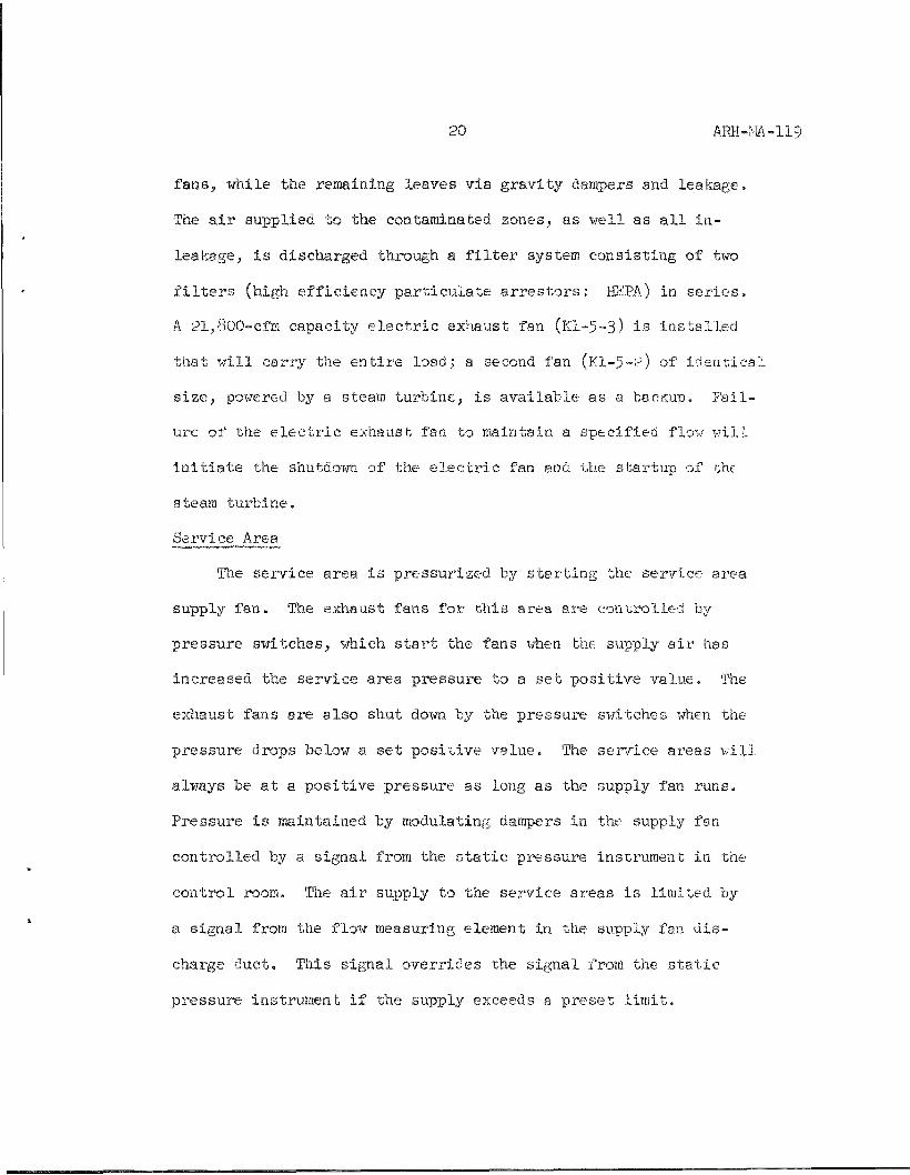
f a n s , while the remaining leaves v i a g r a v i t y dampers and leakage .
The a i r suppl ied t o the contaminated zones, as we l l as a l l i n -
leakage , i s d ischarged through a f i l t e r system c o n s i s t i n g of two
f i l t e r s (high e f f i c i e n c y p a r t i c u l a t e a r r e s t e r s : HB-PA) in s e r i e s .
A 21,800-cfm capac i ty e l e c t r i c exhaust fan (KI-5-3) i s i n s t a l l e d
t h a t w i l l c a r ry the e n t i r e load; a second fan (Kl-5-2) of iden 'c ica l
s i z e , powered by a steam t u r b i n e , i s a v a i l a b l e as a bacgup. F a i l
ure of the e l e c t r i c exhaust fan to maintain a spec i f i ed flow wilL
i n i t i a t e the shutdown of the e l e c t r i c fan and the s t a r t u p of r;he
steam tui-bine.
Service Area
The s e rv i ce area i s p r e s s u r i z e d by s t a r t i n g the sei-vice area
supply f an . The exhaust fans f o r t h i s a rea a re con t ro l l ed by
p r e s su re swi t ches , which s t a r t the fans when the supply a i r has
inc reased the s e r v i c e area p r e s su re to a s e t p o s i t i v e v a l u e . The
exhaust fans a re a l s o shut down by the p re s su re switches when the
p r e s s u r e drops below a s e t p o s i t i v e v a l u e . The s e rv i ce a reas w i l l
always be a t a p o s i t i v e p r e s s u r e as long as the supply fan runs .
P re s su re i s maintained by modulating dampers in the supply fan
c o n t r o l l e d by a s i g n a l from the s t a t i c p res su re ins t rument in the
c o n t r o l room. The a i r supply to the s e r v i c e a r ea s i s l imi t ed by
a s i g n a l from the flow measuring element in the supply fan d i s
charge duc t . Tliis s i g n a l o v e r r i d e s the s i g n a l from the s t a t i c
p r e s s u r e ins t rument i f the supply exceeds a p r e s e t l i m i t .

21 ARH-HA-119
The supply fan motor automatically shuts off on a signal
from the flow instrument if the fan has failed. Shuttin£; off the
supply fan motor is aniunciated in the concrol rooiiu
Process Area
The negative pressure in the process area is aormally waia-
tained by operating tae electric exhaust fan. After startinff tais
fan, the supply fan starts automatically as the pressure in the
pump room approaches the required negative Talue. The arnoimb of
supply air is limited to a pi-eset value and is controlled by
modulating dampers in the supply fan. A signal from the flow
measuring element in the supply fan duct controls the dampers,
A loss of flow from bhe supply fans signals for a shutdown of the
supply fan motor which is annunciated in the control room.
The exhaust air from bhe process area is monitored for radi
ation. Any indication of filter breakthrough will shut ao' m both
the electric and the steam turbine exhaust fans, which in turn
will shut down the supply fan upon loss of nei a&ive pressure in
the process zones.
The differential pressures across both the first and second
HEPA filters in the exhaust system for the process areas are also
monitored. A low differential pressure across either the first or
second filters could indicate a filter breakthrough while a high
differential pressure across the first filter could indicate filter
pluggage with a potential for breakthrough. Each is annunciated in
the control room.

22 ARH-MA-119
Operat ing Area
The operat ing, a rea p r e s su re i s con t ro l l ed a t a spec i f i ed
nega t ive p r e s su re by modulating dampers in the exhaust fan . These
dampers modulate on a s i g n a l from the ins t rument monitor ing the
s t a t i c p r e s s u r e in the pump room. This p re s su re c o n t r o l l e r a l so
shu t s dovra the supply i f the requi red nega t ive p r e s su re cannot be
maintained by completely opening the modulating dampers in the
exhaust fan .
Condensate Tank (TK-C-lOO) Ref. 24
Condensibles from the v a p o r - l i q u i d s e p a r a t o r a re co l l ec ted
in a 17,OOO-gallon, s t a i n l e s s s t e e l , round-bottomed tank (see
F i g . i B ) . Condensate d r a i n s i n t o t h i s tank from the primary
condenser, the i n t e r - and a f t e r condensers , and the v e s s e l vent
s e a l p o t . An i n l i n e pump (P-C-lOO) moves the condensate through
a f i l t e r (F -C- l ) to an ion exchange column ( i X - B - l ) , a f t e r which
i t may be d ive r t ed by the R-C-3 d i v e r t e r valve back to the C-lOO
catch tank i f i t does no t meet d i scharge s p e c i f i c a t i o n s . Condensate
meeting s p e c i f i c a t i o n s i s routed to the 216-S-25 c r i b .
The condensate catch tank has overflow and d ra in l i n e s to
tank 103-S. A vent l ead ing to the v e s s e l vent system i s equipped
with a manually c o n t r o l l e d a i r b l e e d - i n valve which provides
s u f f i c i e n t a i r flow to p reven t the f i l t e r low dp i n t e r l o c k from
s h u t t i n g down the v e s s e l ven t exhaus t e r . The bank has a vent
from the flow measurement tank (C-IO3), a p a r t of the R-C-1

23 ARH-MA-119
sampling system. It is also equipped with a liquid level gauge,
agitator, temperature element, W/SpG Instrumentatioa, and two
interface instruments to detect any organic that may accumulate
in the tank. A spray nozzle from the decot.taraiiiation tank is
provided for flushing of the tank. (This flush solution may also
be used to flush the condensate filter and then be rtcycled back
to TK-C-100.)
Condensate Pump (P-C-lOO) Ref. 2, p. 102
The carbon steel condensate pump transfers condensate fz'om
the C-lOO catch tank to the ion exchange column. Its normal
operating capacity is 60 gpm, while maximum capacity is 75 gpm-
The 10 HP centrifugal pump has a total dynamic head of I63 feet.
Condensate Filter (F-C-l) Ref. 2, p. 104
The condensate filter with a 5-micron rating is located on
the process condensate line to prevent particulate matter from
reaching the ion exchange column. It consists of cellulose fiber
material and melamine resin. The Cuno filter assembly has 36 dis
posable cartridges and can handle a flow rate of 220 gpm when clean.
Two pressure indicators are located upstream and downstream of the
filter to determine the differential pressure.
Ion Exchange Column (IX-D-I) Rpf. 25
Process condensate collected in tbe C-lOO tank is pumped
through the 1133-gallon ion exchange column for reduction of

24 ARH-MA-119
137 • 'Cs concentration. Strontium-90 is also removed by filtration.
The column, which has a four-foot OD and a l6'-l" overall height,
normally contains approximately 125 ft3 of Zeolon-900 resin
provided in the form of a dry, granular solid. The exchange
column, designed for do-smflow loading and upflow elution, is
regenerated as necessary by pumping the eluant from the aqueous
makeup tank (E-lOl) upflow through the column and discharging it
to TK-103-S. Raw water is also piped to the ion exchange column
to serve both for backflushing the colxomn and for displacing the
old resin whenever necessary. The upflow can exit either through
a three-inch drain at the top of the column or through a bhree-inch
drain located immediately below the upper screen.
Screens in the exchange column are situated 7'-8" apart and
are l6 x 200 mesh Dutch weave. Three pressure indicators are
located in the column: one directly below the top screen, and one
on either side of the lower screen.
Process condensate enters the bop of the column from the C-100
tank, and exits through the bottom to the 216-S-25 crib, via the
in-line filter and R-C-3 diversion valve. A small portion of the
flow is drawn through the R-C-3 proportional sampler and radiation
monitor and then discharged bo tank C-100. Two three-inch drains
(located on top and bottom of the column) lead to TK-103-3, as do
the overflow and resin drain lines. A three-inch line is also
provided to funnel resin into the column (see Fig. 19)•

25 ARH-MA-119
An in-line filter is installed in the process condensate
line downstream of the ion exchange bed to collect resin which
escapes through the bottom screen of the column. The filter
arrangement consists of two parallel filters with removable
baskets, both of which are provided with 200-mesh screens dur
ing normal operation. It is also equipped with a filter by-pass
line, pressure gauges upstream and downstream of the filter, and
a sight glass located upstream of the filter arrangement.
A new ion exchange column (Fig. 20) is being aesigned at the
time of this writing and can be found in drawings H-2-46040 through
H-2-46o44. Major features of the new design include the following:
1. Diverter valve P0V-RC3-1 can divert process condensate from the 216-S-25 crib bo either the C-100 or 103-S tanks.
2. The integrator at the control panel for flow meter FM-RC3-1 will shut off when the diverter valve is in the C-100 or IO3-S position, measuring only the flow to the crib.
3. A new PRV (and by-pass line) located after FM-RC3-1 to maintain sufficient flow through the flow meter.
4. A flange Installed in the column 12 inches above the lower screen and bolted upper and lower screen assemblies provide for screen inspection and/or replacement.
5. Two new three-inch side pipe connections installed slightly above the lower screen for resin removal and to provide a by-pass supply of water for back-flow operation.
6. The upper screen mil be 50 mesh stainless steel, while the lower one will be 100 mesh stainless steel with a l40-micron retention.

26 AM-MA-119
Eluant Tank (TK-E-lOl) Ref, 2, p. 93? 23
The eluant tank is a ^,200-gallonj stainless steel tank which
measures nine feet high by nine feet in diameter (see Fig. 21), It
is heated by a steam jacket with a minimum heating surface of
197 f't'« Condensate from the jacket is routed to 216-U-lO pond.
The tank is provided with a centrally located^ stainless steel
agitator to improve heat transfer and to keep solids in suspension.
It is also equipped with a temperature element and w/SpG instru
mentation. Overflow and drain lines lead to tank 103-S, and it
has a pump-out line to the ion exchange column. The E-101 tank
is vented to the roof and is provided with a three-inch line and
a 10-inch port for raw water and chemical addition, respectively.
Eluant Pump (P-E-lOl) Ref. 2, p. 98
The carbon steel eluant pump, which has a total dynamic head
of 105 fee'c, pumps eluant to the ion exchatige column for regeneration
of the resin. The 7 o HP centrifugal pump has a normal operating
capacity of 100 gpm and a maximum capacity of 120 gpm.
Anti-Foam Tank (TK-E-102) Ref. 28
The anti-foam tank (see Fig. 22) is a 100-gallon, stainless
steel tank equipped with an agitator and weight factor instrumenta
tion. It has a pump-out line to the evaporator , and its overflow
and drain lines flow to tank IO3-S. The tank is vented to the roof
and has lines for the addition of filtered raw water and chemicals.

27 ARH-iiA-119
Anti-Foam Pump (P-E-102)
Tae v a r i a b l e speodj l/k HP ant;i-foam pump ope ra t e s a t a
0 .01 to 0 .1 gpm capac i t y .
Deecntamination Tank ( T K - E - H ^ ) Ref. ?7
i'he 620-gallon s t a i n l e s s s t e e l decontamination tank (see
F i g . 23) i s heated by a steam j a c k e t which has a minipmrn hea t ing
surface of 2^ f t - . Condensace from i,he j s c t c t , d r a i n s to the
216-U-lO pond. The t a n k ' s overflow and d ra in l i n e s flow to tank
103-S. I t s pump-out l i n e leads to spray nozz les a t the v e s s e l
vent deentrainment unit;, the C-100 tank, the hot equipment room
sumps, and the primary j e t in che jet-vacuum system, as we l l as
to a b lank hose connection in the hot equipment room and pump room.
The tank i s ventea to the roof and has a l i n e for the add i t ion of
raw water and a 10-inch p o r t for chemical a d d i t i o n s . I t i s a l s o
equipped with an a g i t a t o r , a temperature element , and w/SpG
instrumen-ca t i o n .
Decontamination Pump (P-E-10i|) Ref. 2, p . 100
The s t a i n l e s s s t e e l deconiaminaLion pump ope ra t e s a t a 50 to
60 gpm c a p a c i t y . The c e n t r i f u g a l pximp has a t o t a l dynamic head of
196 f e e t and a 10 HP r a t i n g .
Puiffp Room Sump Ref. JQ
The pump room sump, \rhich i s loca ted in the sou theas t corner
of the pump room, measures 60" by 60" by 7 ? - l / 4 " in o v e r a l l depth

28 ARH-MJ\-119
and is lined with l/4" stainless steel. Its contents are routed
to tank 103-S via a steam jet system which utilizes high and low
level switches for automatic startup and shutdown. The addition
of raw -srater allows the minimum level to be maintained. The
loading dock and evaporator room floor drains, ho: equipment
room floor drain and sumps, and the P-B-1 and P-B-2 seal water
flow into the pump room sump. In addition, a drain funnel which
collects any leakage from vacuum relief valves on the anti-foam
line 1301 and decontamination line fiOl drains to the sump. The
sump is also equipped with instruments to measure specific gravity.
R-C-1 Ref. 20
Steam condensate from the 242-S evaporator reboiler is
normally discharged to the 216-U-lO pond, but can be diverted to
tank 103-S. The stream is continuously monitored with radiation
detection instruments, as well as by using a proportional sampler
for obtaining samples for laboratory analyses.
The steam condensate is routed through a ^OO-gallon flow
measurement tank (TK-C-IO3) which is equipped with a flow measure
ment weir (see Pig. 2^). A continuous sample from TK-C-IO3 is
pumped (by P-RCl-l) through a sample cooler to reduce the conden
sate temperature, and then through a sample valve, which is monitored
by a rotameter (see Fig. I6). The sample continues on through the
radiation detector and is then returned to the sampled stream. How
ever, the sample flow can be diverted to by-pass Ae radiation

29 ARH-M-119
cell (KE-RCl-l) and allow the cell to drain to obtain a background
radiation reading. The radiation cell is flushed if the back
ground level is increasing. If high radiation is detected in the
cell or the in-line radiation monitor (RE-EAl-l), the steam con
densate flow is diverted from tne 216-U-lO pond to TK-103-3.
The proportional sampler is controlled by the steam condensate
flow over the weir such that when a specific volume of condensate
(normally 10 gallons) has passed over the weir, a signal is re
ceived from the flow totalizer. This signal triggers the operation
of the proportional sample valve which turns to discharge the small
increment of sample contained in the valve to the sample receiver.
Meanwhile, the main sample stream continues to flow through the by
pass. After discharging the sample increment, the valve repositions
for sample flow through the valve. The sample valve is air blown
each sampling operation to ensure that the entire sample reaches the
sample receiver. The remaining contents of the sample receiver after
the sample for the lab has been taken is drained into the sample
drainline, which returns to the flow measurement tank dovmstream of
the weir.
R-C-2 Ref. 20
Used raw cooling water from the primary and after condensers is
discharged to the 216-U-lO pond. A small portion of this flow is
routed through the R-C-2 proportional sampler and radiation detector,

30 ARH-ivlA-119
which works e s s e n t i a l l y the same as the R-C-1. The sample stream
i s then re tu rned to the normal flow (see F i g . 2k). The d i f f e r e n t i a l
p r e s su re ac ross an o r i f i c e mainta ins sample flow to the sampler; a
manual valve doisTistream of the o r i f i c e flow meter mainta ins p res su re
on the l i n e to assure t h a t the l i n e i s completely f i l l e d a t the
o r i f i c e . The p r o p o r t i o n a l sampler i s con t ro l l ed by the o r i f i c e
flow meter such t h a t when a s p e c i f i c volume of waste cooling water
(normally 1000ga l lons ) has passed through the meter , a small amount
of waste i s d ischarged to the a i r - s p a r g e d sample r ece iv ing tank for
a l a t sample to be ta-:en. A programmer au toma t i ca l l y a i v e r t s the
sample flow t o by -pass the r a d i a t i o n c e l l (KE-RC2-1) for f ive
minutes each hour while the c e l l i s allowed to dra in to check the
r a d i a t i o n background read ing , A high r a d i a t i o n reading on the coo l
ing water stream i s not a n t i c i p a t e d , and t h i s stream cannot be
d i v e r t e d . I f the stream becomes contaminated, a p l a n t shutdoim i s
r e q u i r e d .
R-C-3 Ref. 20
Process condensate from the 2'i2-S evaporator is normally dis
charged to the 216-S-25 crib via the C-100 tank and ion exchange
column. A portion of the ion exchange discharge stream is pumped
(by P-RC3-1) through a proportional sampling, radiation monitoring,
diversion system (R-C-3) which is similar to R-C-1 and R-('-2j this
sample stream is routed to TK-C-100 after passing throi^h R-C-3. A

31 ARH-I'lA-119
magnetic flow meter controls the proportional sampler such that
small amounts of condensate are discharged periodically (usually
every 10 gallons) to the sample receiving tank. Condensate flow
is diverted for five minutes each hour to allow the radiation
cell (RE-RC3-1) to drain to provide a check of the radiation back
ground (see Fig. 24). Radiation readings above a specified amount
result in diversion of the process condensate back to the C-100
tank.
Air Sample Radiation Monitoring Systems Ref. 3J 19
The air sample radiation monitoring systems include (l) the
room air sample radiation monitorsj (2) the building exhaust stack
radiation monitors; and (3) the vessel vent stack radiation moni
tors. Refer to Figure 25 for an engineering flow diagram of these
systems.
The room air systems each consist of a beta-gamma Geiger
Mueller (GM) tube mounted in an air sampler, a preamplifier, and
a linear count rate meter with an integral power supply and alarm
circuit. The solid state count rate meter has a potentioraetric
output; it converts input pulses from the preamplifier into a
direct current (DC) voltage proportional to the average count rate.
It is provided with two adjustable alarm settings: one for an
"alert" condition and the second for a "high" condition. The room
air radiation monitors are located in the AiU room (R-AS-l), change

32 ARH-M-119
room (R-AS-2), control room (R-.AS-3), and the instrument loft
of the condenser room (R-AS-4).
Air is drawn through the room air samplers by a vacuum pump
(P-AS-l). The air sampling piimp also drax/s air samples from the
ion exchange column room, the loading dock room, loadout and hot
equipment storage room, pump room, and evaporator room, as well as
two samples from the JiEPA filters of the building exhaust system
(see Fig. 25). The flows are regulated in each case by means of a
flow indicator; they flow into a two-inch line passing through an
air filter (F-AS-1), the air sampling pump, air/water separator-
silencer, and into the vessel vent exhaust stack. The air sampling
pump operates at 125 scfm and 6" Hg vacuum. Raw water to maintain
the pump seal is supplied at approximately k gpm.
An air sampler probe draws air from the vessel vent stack into
the radiation monitoring system. To prevent condensation in the
sample stream, instrument air (20-pound) passes through an air dryer
and a heater into the stream. The sample stream is then divided into
two parts, each passing through a filter paper, and pumped by a vacuum
pump (P-AS-2) back to the vessel vent stack. Particulate matter
collected on one filter paper is continuously monitored for alpha by
the vessel vent radiation monitor, while the other is routinely col
lected for beta and gaiama readings. The vessel vent radiation moni
tor includes a GM counter, solid state high voltage DC power supply,
amplifier-discriminator, and a count rate meter. The GM counter has

33 ARH-l.m-119
a background of 60 counts per minute maximum (at operating voltage
and shielded by l/4" aluminum inside 2" of lead) and is utilized
for alpha, beta, and gamma energy detection. The transistorized
count rate meter is provided with a choice of linear or logarithmic
presentation and has a potentiometrie output.
Air from the building exhaust system enters the building
exhaust stack where a portion of it is dra>m through an air
sampler probe. Process air (90-pound) passes through an air dryer,
a PRY, and a heater and is added to the stream to prevent condensa
tion. The sample stream is monitored for radiation (the monitor is
similar to the vessel vent radiation monitor) and pumped back to the
exhaust stack by a vacuum pump (P-Kl-l).
Slurry Sampler Ref. 17
A sampler arrangement is attached to the slurry recirculation
loop by-pass line in order to obtain slurry samples for laboratory
analyses. Data from the slurry samples will provide a basis for more
precise control of the 242-S operating parameters affecting process
quality. The sampler is located on the south wall of the hot equip
ment storage room. It is being redesigned at the time of this
writing.
Process Air Supply System Ref. 2, p. 64; l8
Components of the process air system include two identical air
compressors (CP-E-1, CP-E--2) installed in parallel, an air receiver
(R-E-I), an aftercooler (E-E-6), a separator, and two dryers (DR-E-1,

3^ ARH-14A-119
DR-E-2) (see F i g . 7 ) . The compressors a re v e r t i c a l , r e c i p r o c a t i n g ,
non - lub r i ca t ed compressors and are designed to d e l i v e r 100 scfm
a t 100 p s i g . Each i s cooled with a t rater j a c k e t using water a t a
maximum of 70 "^F. Used cool ing water i s routed to the 216-U-lO pond.
One compressor i s used as the o n - l i n e u n i t ; the o the r i s used as a
stand-by u n i t which i s u t i l i z e d only i f the o n - l i n e compressor f a i l s .
Such a f a i l u r e could be the r e s u l t of l o s s of o i l p ressure , , or com
pressed a i r o r cooling water temperatures above p r e s e t l i m i t s . In
a d d i t i o n , the s tand-by u n i t s t a r t s end the o n - l i n e compressor shuts
off i f the ope ra t ing p res su re drops below a p r e s e t v a l u e .
The a f t e r c o o l e r i s a h o r i z o n t a l p i p e l i n e type t h a t inc ludes a
moisture s e p a r a t o r , a s igh t - f l ow cooling water d i scharge and a
s e p a r a t o r d ra in valve (both of which dra in to the 21b-U-10 pond), an
automat ic condensate t r a p , and a d ischarge a i r temperature i n d i c a t o r .
The u n i t , s i zed to h a a i l e a minimum of 200 scfm of a i r , i s designed
as a w e t - s h e l l u n i t wi th an a i r tube s i d e .
From the a f t e r c o o l e r the process a i r i s routed to the a i r
r e c e i v e r , a s t e e l upr igh t tank with a volume of l l j cubic f e e t . The
15-foot high a i r r e c e i / e r i s equipped with a manhole, a s a fe ty r e l i e f
va lve s e t a t 125 p s i g , a p r e s su re gauge, a mois ture t r a p , and a d ra in
valve to the 216-U-lO pond. Process a i r i s routed from the a i r r e
c e i v e r to va r ious l o c a t i o n s in the o p e r a t i o n , such as the R-C-1,
R-C-2, R-C-3 samplers , while ins t rument a i r cont inues on through a
d rye r system. This system c o n s i s t s of a twin tower Onad dryer with

35 ARH-I.m-119
steam heat reactivation. Its operation is fully automatic; it
operates on a txrelve-hour reversal cycle with a four-hour re
activation heating period. Each dryer is equipped with a steam
trap and drain lines for routing steam condensate to the 216-U-lO
pond. After drying, the instrument air passes through a I-I/2"
line to various locations such as WP/SpG tubes and remotely oper
ated valves.
Overhead Crane Ref. 5
A 5-1/2-ton bridge crane services the pump room, loadout and
hot equipment storage room, and the loading room. It consists of
a motor-driven, under-running bridge with a single girder supporting
its five-ton hoist and an outrigger supporting its one-half-ton hoist.
Its combined hoist capacity is 11,000 pounds and it is capable of
handling a load of 125 percent of that capacity. In the event of
electrical or mechanical failure of any of the bridge drive com
ponents, the crane retrieval system moves the crane bridge (with a
two-ton load) to the north extremity of the crane rails.
Interlocks
Interlock Mumber One
Interlock number one is activated if the bottoms concentrate
flow decreases below a specified value. It initiates a shutdown of
the slurry pump (P-B-2) and a line flush with water. The interlock
will perform the following functions automatically:

36 ARH-MA-119
1. An indication of low flow sounds alarm FA-C#l-4 (low slurry flow annunciator), and s t a r t s the time delay relay timing out.
2. After the eight-minute time delay relay has timed out, the selector switch SS-CAl-2 (which i s normally in the number one posit ion to set the system for automatic flushing of the slurry pump-out l ine) i s by-passed regardless of the operation that had been manually selected.
3. Solenoid valves are energiztd so that POV-CAl-2 and P0V-CA1-2A are positioned for flushing back to tne evaporator, tsius shutting off flow to the bottoms concentrate pump.
4. P-B-2 pump i s shut off.
5. After the timed flush of the l ine back to the evaporator, POV-CAl-2 and POV-CAl-3 are positioned for a timed flush of the bottoms concentrate l ine to the pump and on to the bottoms receiving tank.
6. After the tank farm flush, P0Y-CA1-2A i s positioned for flushing towards the evaporator. With POV-CAl-2 positioned to flush the tank farm, there i s no flow and the flush i s completed.
The P-B-2 pump remains off, and POV-CAl-2 and P0V-CA1-2A remain
in the "no flow" position un t i l a reset button i s pushed. Upon r e
se t t ing , the slurry pump r e s t a r t s and s lurry flow to the farm i s
resumed.
liJhen the low flow alann switch i s opened, i t s t a r t s a timer on
the main panel boara. This timer, which i s manually controlled,
t e l l s the operator how long he has to correct the problem before the
s lurry pump shuts off and the automatic flush of the slurry l ine
begins. The timer can be rese t by pushing a rese t button (IIS-CA1-4C);
a selector switch SS-CAl-4 i s also provided for by-passing the auto
matic flush provisions i f so desired.

37 ARH-m-119
Interlock Mumber Two
A loss of power to the recirculation pump (P-B-l) will
activate the number two interlock to initiate automatically a
complete shutdown and dumping of the slurry from the evaporator.
The interlock performs the following operations:
1. Alarm FA-CA1-3B (28-inch recirculation line bypass low flow annunciator) sounds, Indicating loss of flow.
2. Interlock number ten is activated, which shuts off steam to the reboiler and desuperheater. The reboiler chest is also pressurized with 20 psig air.
3. A time delay relay is started; the operator has a preset length of time (adjusted from one to ten minutes) to correct the problem and restart the recirculation pump before the automatic interlock circuit initiates a dump of the evaporator contents. Auditional time can be obtained by pushing a manual switch (MS-PBl-2 "start") to reset the circuit. Switch IIS-PBl-2 "stop" must be pushed to reinitiate the automatic dump sequence.
4. When the time delay relay has timed out, automatic shutdown of the evaporator is initiated in the following sequence:
a. evaporator feed valve DOV-CAl-1 is closed;
b. evaporator feed pump 241-S-P-102 is stopped;
c. vacuum breaker valve POV-PX'l-l is opened;
d. steam valve to the inter- and after condenser vent jets is closed.
5. Automatic dump of the evaporator is initiated by the following:
a. bottoms dump valve BDV-CAl-7 is opened and a time delay relay started;
38 ARH-I4A-119
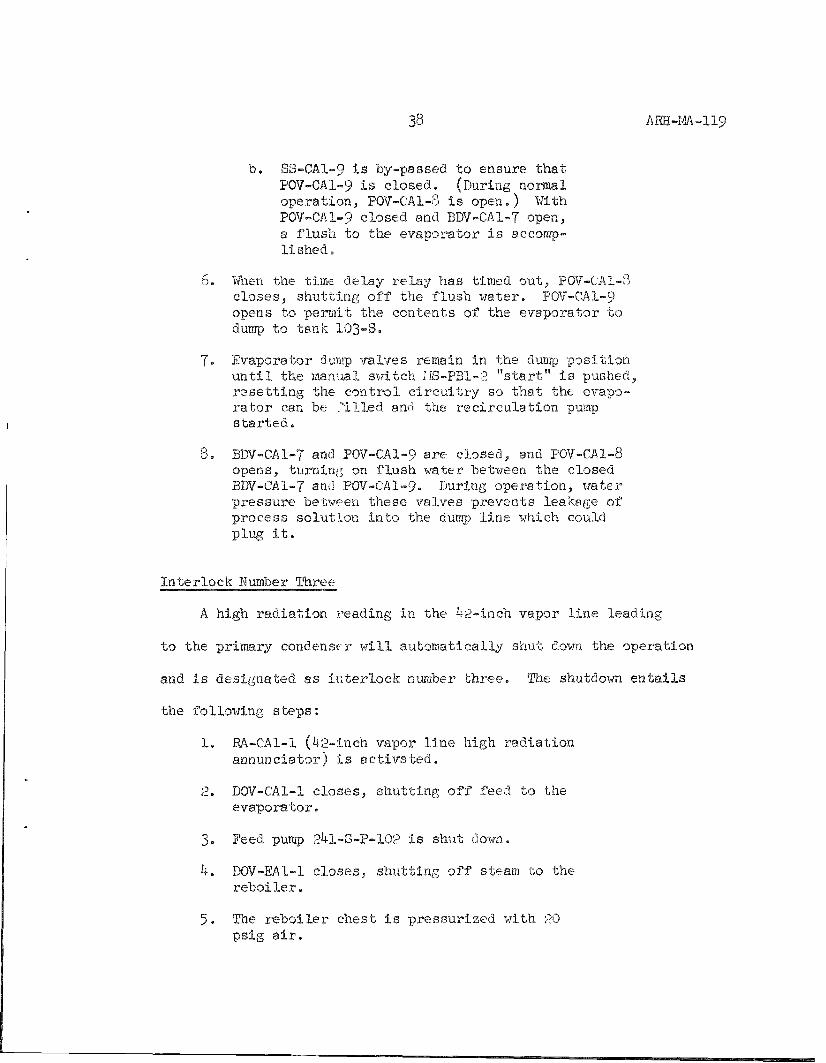
b. SS-CAl-9 is by-passed to ensure that POV-CAl-9 is closed. (During normal operation, POV-CAl-3 is open.) With POV-CAl-9 closed and BDV-CAl-7 open, a flush to the evaporator is accomplished.
6. When the time delay relay has timed out, POV-CAl-55 closes, shutting off the flush water. POV-CAl-9 opens to permit the contents of the evaporator to dump to tank IO3-S.
7. Evaporator dump valves remain in the dump position until the manual switch IIS-PBl-2 "start" is pushed, resetting the control circuitry so that the evaporator can be Tilled and the recirculation pump started.
8. BDV-CAl-7 and POV-CAl-9 are closed, and POV-CAl-8 opens, turning on flush water between the closed BDV-CAl-7 and POV-CAl-9. During operation, water pressure between these valves prevents leakage of process solution into the dump line which could plug it.
Interlock Mumber Three
A high radiation i-eading in the 42-inch vapor line leading
to the primary condenser will automatically shut down the operation
and is designated as interlock number three. The shutdo-vm entails
the following steps:
1. RA-CAl-1 (42-lnch vapor line high radiation annunciator) is activated.
2. DOV-CAl-1 closes, shutting off feed to the evaporator.
3. Feed pump 241-S-P-102 is shut down.
4. DOV-EAl-1 closes, shutting off steam to the reboiler.
5. The reboiler chest is pressurized with 20 psig air.

39 ARH-im-119
6. The a i r to DC/-EA1-4 i s turned off, s h u t t i n g off steam t o the desuperhea te r .
I n t e r l o c k number Four
The number four i i t e r l o c k system i s designed to shut down
the v e s s e l vent exhaus te r and the evapora tor in the event the
v e s s e l vent f i l t e r s slrould f a l l o r f a i l u r e appears imminent.
There a re four monitoiLng systems tha t can i n i t i a t e t h i s s n t t -
down:
a . High r a d i a t i o n in the s tack gas a c t i v a t e s RA-AS-5 ( v e s s e l vent rxhaust s tack high r a d i a t i o n annunci a t o r ) .
b . Low d i f f e r e n - l a l ac ros s the number one ilEPA f i l t e r could i n d i c a t e f i l t e r breakthi-ough and a c t i v a t e s DPA-FC5-1 ( F - . - 5 , low d i f f e r e n t i a l p r e s su re annunci a t o r ) .
c . Low d i f f e r e n t i a l a c ro s s the number two HEPA f i l t e r s i m i l a r l y a c t i v a t e s DPA-FC5-2 ( F - C - 5 , low d i f f e r e n t i a l p r e s su re a n n u n c i a t o r ) .
d. High d i f f e r e n t i a l ac ros s the number one HEPA f i l t e r I n d i c a t e s the f i l t e r i s plugging o r wet. I t a c t i v a t e s DPA-FC5-IA (F-C-5, high d i f f e r e n t i a l p r e s su re a n n u n c i a t o r ) .
The shutdown e n t a i l s the fol lowing s t e p s :
1. BOV-CAl-1 c l o s e s , s h u t t i n g off feed t o the evapora to r .
2 . Feed pump 241-S-P-102 i s shut down.
3 . POV-ECl-1 opens, b leeding a i r from the evapora tor room i n t o the vent system to break the vacuum to the evapo ra to r .
4 . POV-EC2/EC3-1 c l o s e s , s h u t t i n g off the steam t o the vacuum j e t s .

40 ARH-M-119
5. DOV-EAl-1 closes to shut off steam to the reboiler.
6. EV-EAI-3 is deenergized, turning on 20 psig air to the reboiler.
7. DOV-EAl-4 closes to shut off the steam to the desuperheater.
Interlock Humber Five
A high radiation reading on the process condensate monitor
(RE-RC3-1) will activate the following operations:
1. EV-RC3-3 is deenergized; it operates P0V-RC3-1 to divert the process condensate from the crib back to tank C-lOO,
2. The proportional sampler valve is held in the straight-through flow position, so that no more sample is collected in the sample collection tank after the condensate stream is diverted. The sample represents only that condensate which has been I'outed to the crib,
3. Process condensate pump (P-C-lOO) is shut doim.
4. RA-RC3-1 (process condensate high radiation annunciator) is activated.
Interlock Mumber Six
1. A high radiation in the steam condensate Line (monitored by RE-EAl-1) initiates number six interlock, which will:
a. activate RA-EAl-1 (steam condensate high radiation annunciator);
b. deenergize EV-EAl-1, shutting off steam to the reboiler;
c. position POV-EAl-2 to divert the steam condensate from the pond to the waste storage tank 103-S, by-passing the steam condensate proportional sampler.

41 ARH-M-119
2. Should the high radiation alarm on the steam condensate line fail to catch a breakthrough of contamination, the steam condensate proportional sampler and monitor should pick it up. A high radiation reading at the monitor (EE-RCl-l) will:
a. activate RA-RCl-1 (steam condensate, high radiation annunciator);
b. deenergize EV-EAl-1, shutting off steam to the reboiler;
c. position POV-RCl-1 to divert the steam condensate to the waste storage tank 103-S;
d. hold the proportional sampler valve in the flow-through position so that no more sample is collected after the condensate stream is diverted. The sample represents only that condensate which has been routed to the pond.
Interlock Mumber Seven
The supernatant pumps in the bottoms tanks and the slurry
pump (P-B-2) have interlocks to prevent the pumping of waste solu
tion into the steam and water flush lines. Limit switches are
installed on the flush valves in the supernatant system flush jum
pers located in the valve pits. Opening any flush valve shuts
down all supernatant pumps. Pressure switches on the flush headers
in the flush pits prevent pump operation if a flush header is
pressurized.
1. The opening of any LS-241- or PS-24l-contacts in the supernatant pump controls interlock circuit leads to shutting down the supernatant pumps.
2. The opening of any PS-24l-contacts in the slurry pump control interlock circuit will:
a. activate PA-24lS/SX-l (slurry flush line high Dressure annunciator);
b. shut down the slurry pump (P-B-2).

42 ARII-M-119
Further protection is provided by monitoring the flush supply
lines for radiation at a point where the lines enter the farm.
Should all other devices fail and waste is pumped back through
the supply lines, the radiation detector Interlock shuts dovm all
supernatant pumps and the slurry pump, and activates RA-SP-1 (raw
water and steam line high radiation annunciator).
Interlocks installed on the feed pump for protecting the
water and steam flush headers are the same as for the supernatant
and slurry pumps. Pressure switch PS-241-S-102, limit switch
LS-241-S-102, and the radiation alarm relay all have contacts in
the feed pump control circuit.
Interlock Humber Eight
The evaporator-crystallizer normally operates at a negative
pressure of approximately 28 inches of Hg vacuum. Any increase in
pressure is an indication of trouble, such as foaming, deentrainer
flooding, or insufficient cooling of the vapor. An evaporator
pressure that exceeds a maximum acceptable level will:
1. activate PA-CAl-4 (vapor-liquid separator high pressure annunciator);
2. close DOV-EAl-1, shutting off steam to the reboiler;
3. close DOV-CAl-1, shutting off the feed to the evaporator;
4. shut down the feed pump (241-S-P-102).
43 ARH-M-119
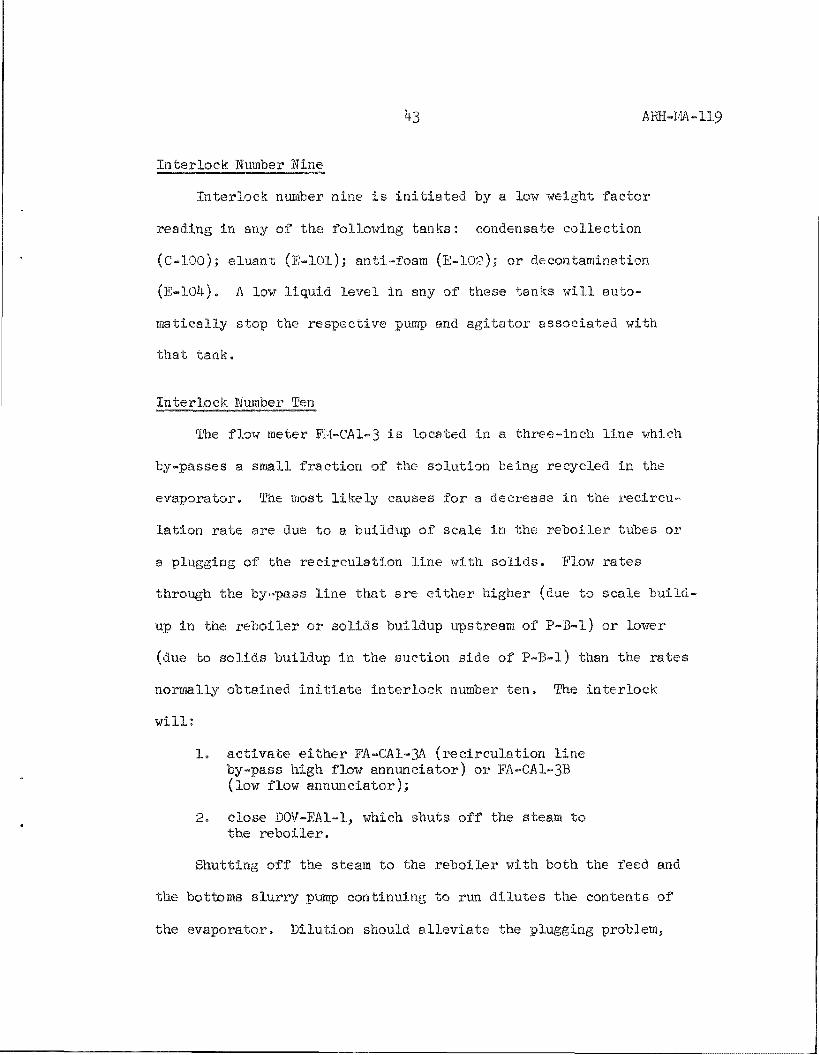
I n t e r l o c k Mumber Hine
I n t e r l o c k number nine i s i n i t i a t e d by a low weight f a c t o r
reading in any of the fol lowing t a n k s : condensate c o l l e c t i o n
(C-lOO); e l u a n t ( E - l O l ) ; ant i - foam (E-102); or decontamination
(E-104) . A low l i q u i d l e v e l in any of these tanks w i l l a u t o
m a t i c a l l y s top the r e s p e c t i v e pump and a g i t a t o r a s soc i a t ed with
t h a t t ank .
I n t e r l o c k Mumber Ten
The flow meter FM-CAl-3 i s located in a t h r e e - i n c h l i n e which
by-passes a smal l f r a c t i o n of the so lu t i on being recycled in the
evapora to r . The most l i k e l y causes for a decrease in the r e c i r c u
l a t i o n r a t e a re due t o a bu i ldup of sca le in the r e b o i l e r tubes or
a plugging of the r e c i r c u l a t i o n l i n e wi th s o l i d s . Flow r a t e s
through the by-pass l i n e t h a t a re e i t h e r h igher (due to s ca l e b u i l d
up in the r e b o i l e r o r s o l i d s bui ldup upstream of P -B- l ) or lower
(due to s o l i d s bu i ldup in the suc t ion s ide of P-B- l ) than the r a t e s
normally obta ined i n i t i a t e i n t e r l o c k number t e n . The i n t e r l o c k
w i l l :
1. activate either FA-CA1-3A (recirculation line by-pass high flow annunciator) or FA-CA1-3B (low flow annunciator);
2. close DOV-EAl-1, which shuts off the steam to the reboiler.
Shutting off the steam to the reboiler with both the feed and
the bottoms slurry pump continuing to run dilutes the contents of
the evaporator. Dilution should alleviate the plugging problem,

44 ARH-M-119
and the recirculation flow should return to normal. When the
recirculation rate has returned to normal, the flow alarm
switch which is tripped resets and the steam is turned back on
to the reboiler. Process parameters should be evaluated in order
to make the necessary adjustments to prevent overconcentration
from recuri-ing.
Interlock Mumber Eleven
A high radiation reading in the builaing exhaust stream
initiates the number eleven interlock, which will:
1. alai'm RA-Kl-1 (building exhaust stack high radiation annunciator);
2. shut down electrical exhaust fan (Kl-5-3);
3. prevent the backup fan (powered by a steam turbine) from starting.
The building supply fan will shut off automatically due to the
pressure Interlock,
Interlock Mumber Twelve
The liquid level in the vapor-liquid separator is monitored
with weight factor dip tubes. If the weight factor controller
fails, interlock number twelve prevents overfilling of the evapo
rator by the following:
1. Two alarm switches are set to trip if the liquid level exceeds a preset value. If both high weight factor alarm switches l-JPAS-CAl-lB and WAS-CA1-2B trip:
a. DOV-CAl-1 closes, shutting off feed to the evaporator;
b. the feed pump (241-3-P-102) shuts off.

45 ARH-M-119
High l e v e l alarm switches VJFAS-CAl-lA and WFA3-CA1-2A are
s e t t o alarm a t a lower l i q u i d l e v e l than the i n t e r l o c k swi tches .
This a l e r t s the ope ra to r t o the problem p r i o r to the i n t e r l o c k
shutdown of the feed pump.
WAS-CAl-lB and WFAS-CA1-2B a re normally closed and a re
arranged in p a r a l l e l , making i t necessary to have both t r i p to
a c t i v a t e the i n t e r l o c k . These switches opera te from sepa ra t e d ip
legs to prevent a plug in only one a i p tube from a c t i v a t i n g the
i n t e r l o c k .
A s i m i l a r system i s employed for low l i q u i d l e v e l s in the
evapora to r . I f both low weight f a c t o r alarm switches WAS-CAl-lC
and WFAS-CA1-2C t r i p , pumps P-B- l and P-B-2 shut dowti. Th i s , in
t u r n , i n i t i a t e s the number two i n t e r l o c k c i r c u i t .
I n t e r l o c k Mumber Thi r teen
Both the r e c i r c u l a t i o n pump and the s l u r r y pump are equipped
with a water s e a l t o prevent p rocess so lu t i on from leaking out of
the system. The water p r e s su re a t the pump s e a l i s monitored and
p r e s su re switches a re s e t t o shut down the pumps i f the p res su re
drops to a value lov/er than t h a t r e q u i r e d .
Mormal raw water p r e s su re i s s u f f i c i e n t for c los ing p res su re
alarm switch PAS-CAl-3 which i n d i c a t e s t h a t t h e r e i s water p re s su re
a t the pump s e a l fo r P - B - l . Booster pump F-C-I05 must be running to
i nc rea se the water p re s su re so t h a t p r e s su re alarm switch PAS-CAl-2

46 AEH-M-119
closes, indicating that there is water pressure at the pump seal
for P-B-2.
1. A drop in the water pressure to the slurry pump seal (P-B-2) opens PAS-CAl-2, which will:
a. alarm PA-CAl-2 (purge seal to P-B-2 low pressure annunciator);
b, shut down slurry pump P-B-2.
2. Shutting down of the slurry pump results in a "LO Slurry Flow" alarm, activating the number one interlock circuit. The operator has the time it takes for the delay relay to time out to correct the problem before the automatic flush of the slurry line is initiated.
The sequence of operation for a "Lo Pressure Alarm" (PA-CAl-3)
on the water seal to the recirculation pump is identical to the
slurry pump. Interlock circuit number two is activated, rather
than interlock number one, if pressure is not reestablished before
the time delay relay times out.

47 ARH-M-119
APPMDIX
REFEREMCES
1. ffifS-9099 Procurement Specification for Evaporator Recirculation Pump; Hanford Engineering Services
2. HlAfS-9125 Construction Specifications for Evaporator F a c i l i t i e s ; Vitro Fngiueering
3. HWS-9127 Procurement Specification for Air Sample Raaiation Monitoring Systems; Vitro Engineering
4. IWS-9130 Procurement Specification for Bottom Slurry Pump; Vitro Engineering
5. HVJS-9195 Procurement Specification for 5-l/2-Ton Bridge Crane;
Vitro Engineering
6. Exchanger Specification Sheet; Scbutte & Koerting Co.
Struthers
7. 71-04-30917 CI fube Layout for Surface Condenser
3. 71-04-30917 Dll Surface Condenser
9. 71-04-30917 D12 Surface Condenser Details
10. 71-04-30917 DI3 Bundle Details for Surface Condenser
11. 71-04-30917 Dl4 Chanuel Details for Surface Condenser
Tube Layout for Reboiler
Reboiler
Evaporator Crystallizer Outline
Evaporator Details
12. 71-04-31000 C2
13. 71-04-31000 Dl
14. 71-05-10132 Fl
15. 71-07-31027 Fl
Schutte & Koertigg
16. 72-X-E-OOl-J Two-Stage Steam Jet

48 ARK-.M-119
Vitro Engineering
17. H-2-38403 Sampler Enclosure Piping
18. H-2-46327 EFD - Control and AMU Rooms
19. H-2-46330 EFD - Air Sampling
20. H-2-46331 lEFD - Sampling, Monitoring, and Diversion Diagrams
21. H-2-46339 Piping Arrangement - Evaporator Room Plans
22. H-2-46340 Piping Arrangement - Evaporator Room Sections
23. H-2-46355 Eluant Tank (TK-E-lOl) Assembly and Details
24. H-2-46357 Condensate Tank (TK-C-lOO) Assembly and Details
25. H-2-36420 Ion Exchange Column (iX-D-l) Assembly
26. H-2-46361 Vessel Vent System Arrangement
27. H-2-46365 Decontamination Tank (TK-E-104) Assembly and Details
28. H-2-4tS367 Anti-Foam Tank (TK-E-102) Assembly and Details
29. H-2-46369 Pump Room Sump Assembly and Details
30. H-2-46371 Bottoms Pump (P-B-2) Assembly
Unit Job Manual TF-VII, 242-S Evaporator, C. A. Lorenzen
ARH-l601 (unclass i f ied) , Specifications and Standards for the Operation of Radioactive Waste Tank Farms and Associated Facilities, Operations Support Engineering, August 20, 1973J Section J: Specii'lcations and Standards for the Operation
of the 242-S Evaporator-Crystallizer and Associated Waste Storage Tanks, June 30, 1975? W. R. Christensen
ACKMOWLEDGl-'MITS
The author would like to acknowledge W. R. Christensen for his valuable assistance in preparing this information manual.

h9 AEH-M-119
LIST OF FIGURES
Mumber Title
1 Process Flow Diagram
2 EFD - Pump and Evaporator Rooms
3 EFD - Condenser Room
4 EFD - Condenser Room and Ion Exchange Column
5 EFD - Instrument Area, Control and AMU Rooms
6 EFD - Instrument Area and Control Room
7 EFD - Control and Al-O Rooms
8 Vicinity Plot Plan
9 First Floor Plan
10 Second Floor Plan
11 Reboiler
12 Evaporator-Crystallizer
13 Primary Condenser
14 Tube Layout for Primary Condenser
15 Bundle Details for Primary Condenser
16 Tvro-Stage Steam Jet
17 Vessel Vent System Arrangement
18 Condensate Catch Tank
19 Ion Exchange Column
20 Mew Ion Exchange Column
50 Affl-M-119
21 Eluant Tank
22 Anti-Foam Tank
23 Decontamination Tank
24 EFD - Sampling, Monitoring, and Diversion Diagrams
25 EFD - Air Sampling System

7 0 0 ! ; I ^ H > j — ; ^
9 0 PS1&-
- , ^ v
) 0 Ps> ia -
TDE.E.!-^T >«/K.l M M E.NT
& O L M = R O M T K 2 4 1 - l 5 l i , - < : -
" S T E A M - p -
S£:PAQATC5
> / \ C U U M E V A P O R . / ^ T O I ^ - > - K . Y a T A l - L Z . E R V ' f ' "
E M H R . & E K . c t ' S L U R R Y «,
-g. I 5 1 V E R . T £ D S T M I CC'\5D ^ O 1 1 ^ I
„[M^,
HlfaH c F F F 1 L T E K &
<T-E X H A U f e r r R ,
Affl-m-119 Figure 1 Page 51
^ r A . e K .
• % -
C O S i D E M f a A T E
X
- < i ^ - ; Ei-UTEO w A S - r e -V " / - ~ ^ TO T r c - 2 4 i i - > » - i O B
U
C " E M
(_35-l lO & P M )
1-
r M < ^ :
ccKiL'HUi^/^™^ '^/KrcrA T/\r\i5C
SR3AM C A».4*E ^
2 0 t^SlGr
_ - — • ' • iCOlL
' • R . E A X E ' D V R O o e S S C O M D , " X O N E U J 2 l € , - S . C R . 1 &
( I 7 S O O - = V L . J - a 61.0c
< lv iAi t4 P R O C E S S FI .OVU
A U X I l - L / = \ R . Y F i - O V w "
r - l O M l T O K . M < i - , D l V E . R . " s . \ O M 4 P R O P S A M P L E R . & T / » C n O h i
STREAM N ?
BATCH S l l i ( ^
B w a i T Y f e v i i )
•PRESSURE ifsi/l
LIQUIO FLOW'! T O T A L , <it\'. F L O W ( s g • F ^
JITL
t»i-r. "t«»Ty,
N<t O H M/u
N O - C O S C M / L J
N a N O 3 ( M / t )
N o - C l ( M / L )
HaA^OatM/O
OT»iE8% ' M / L )
Fi%% ®i^ ®aeO
S f
VAR 70-12.0 ^ :
^ i^a VA,F6
" O - ' T O > I O
0 . 1 - s . o
TRfcce .
( 2 )
1 0 - 3 0 7 0
\e>-Z5'/^
d/'^ (1/ I d^ i O O O 2 0 0 0
| o
6 5 0 0
< ^ S
2 l , a i 3 0
s a a s
A I R - I f ,
e,
''/an
^' @ ^ j ' "<^ <^ : <^ a- ^u.^ 7 0 0 I Z o O O - K 6 0 0
4 -0
BC^OOO —«-
l-o'"'/<s»,L l-O^VclAu
10 CO T
OP 10
< 0 o l ( , * % .
> 8 o
s & E - ^ j e R - P K _ M o r i = •55
A R e S H O v ^ M OM • & K . - 2 - Z 2 . 1 Z . 3
i 9 " ^ I I
gjjFg 6.TATUS D J .r-_^J!!l^A
^ ^ S !
.LWFIEVO,
J i l ^
g
^ - ^
ONE:
U S . A T O M I C E N E R G Y C O M M I S S I O N
AH Ifc £hi.M HaXd < S £
T^ F. ID 2 4 2 - 5 V A C U U M
^EVAPORATOR-CRYSTALUZER ^^•z.--s>
S K - 2 - 2 2 1 2 8

LQADiKiG
ID£E^TlF!CAIiON SYMBOLS FOR P !P !N6 , aECTRiCAL hW INSTRU-I^ESTATION ARE L'STED ON US i*6S£U 6HD H~2 USSgg
Jf TEgLCSCK SECUEfJCE OF SPERATIOK OF CO^TRSSLS AKD cODLP^^EfiT ON PROCESS N'ALrjNCliON SHALL BE AS L i S T i D OH H 2 IJ6327,
ALL PfPINS MATEPIAL FiTTINGS MANUAL VALVES AHE ACCESSORfgS SMALL MEET ini SPECiFiCATIONS OF THE aPPfSQPRIATE SHEIT 0P IHE M-CODe AS CALLED FOR JN CCKSTRUCTIOH SPEC! F! CAHOfi ! iSS-9 !£5
^ I P i N S SHALL BE iNSJLATED AtJD Fl f l lSHED kS LiSTED !!^ &PEC-!FiCATiO[J HWS-9125
EACH PURGEMETEfi SHALL BE f U M I S H S p \»iTH A DSFFERENTIAl PRfS" SUSE f'eGJLATOF
ALL SST PIPE PENETRATIONS TO DIRECT B y J i l D OUTSIDE Ui^t$ SHALL BE r-ODE S 21 WITH tA I i iODiC PROTECl-!Ofl
FM C A ! - ^ FLOi RA^E iMAi.L BE PROPORIiOS&L T9 N A J I ) W » - ^ L ^ RATE OF m OGO @PM I ?i f9|,C! SCULATtOt* LINE
^ • " D a . S 4 " S M 2 4 ^
(TO VALV£ PIT E4I '5"A1
iO''DR-334 >/?7 (TO TK-24 i -S- IOS^
0" Da-3SSM?e. EJ&POt6&To£ Di^OP-OUT TO T K . - 2 4 I - S - I 0 S
KEV PUAKJ
H Z..si&.52.S M-2'<^tia.fe
H-Z-^^32.^
H S-46»&g.T
M a - ^ & s a ^
M60LW& s. TE&CE
I NEXT ^^^P_^^_J^t4U[^_l'^^
H-2-75 WITH i rRWfegS FCW 0S006
^PExreo - AS suiLT -M ^se
DESCRIPTION
ORAWINS STATUS
£ . / £ & • &
U. S. ATOMIC ENERGY COMMISSIQN i^lCHLAND Oi^ERATIQNS OFFJCE
S N Q I N E E R I N G FLOW O l f i G ^ f i H
PUHP S E V A P O R A T O R RQCNS
?E©J SB i ap - iE5
2 4 2 - S
H -^ -HS 3 2 2 ^

£5 9S»d
6TT-Wf-m¥

i i i
" g H i i 2 i M
- 6 «
ill M i ll
I S
i s - i s » ; I s 3
liiii si a
s
! i ^ ! ! I £ i
11
ihsT I 101' X / Z - « | « < K i 4 ' = « © f f i * ' * ^ ^ B
I 5 = I i I i i I I I 5 a , ifi i
I i ^ 8 A UxtcDo
g o o
k ^
1
5 3 !mm
% '^ i
^ - it
Si'ii s *
tlWV-l-H 33S aNllHOiVN

IILJ
1 'vi^~"
]—r- — j -
i - I ' i l - '
io ^S'r
-C O _^ q ^j _ _ _ _ _ y . _.
ilS i. I.g ^ T
i i l i S2 -I i» 4, /,
^ ; ^
• • ' ^ • , —
•. ' ; 1
1 1
19 4 JJ
to LU
z
3: o
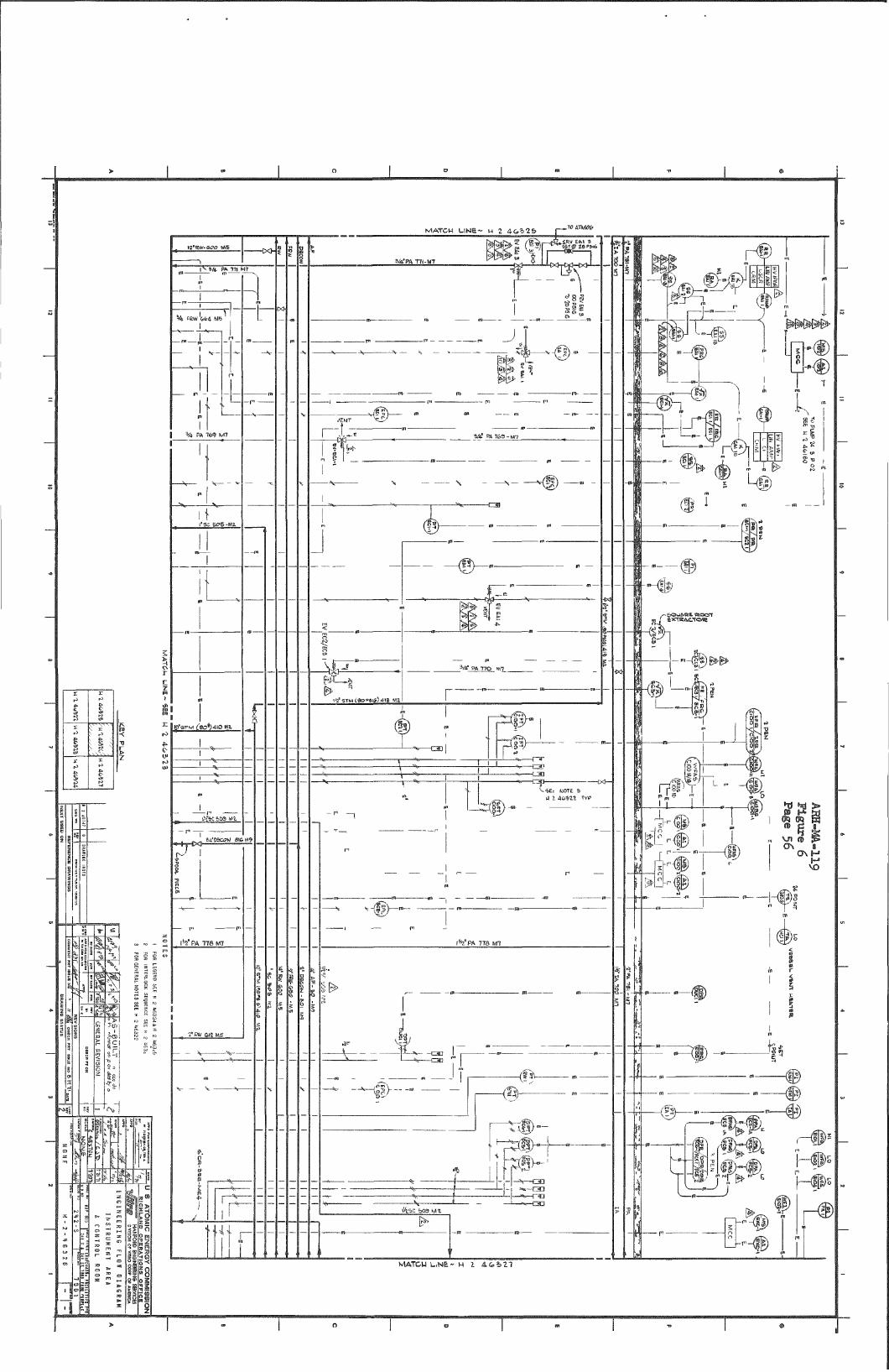
M A T C H L I N S e - H 2 AG'bl^
ig'RW-as?g I
T ^ V4. PA 171 M7
V4 FRwL+MS
„ V ^: 1
* i l PA lb') M7
-Js^, L J > ^
\ ' ' ^ SOS-I
Ip'STM ('eO*}4IO M;.
ifecsoawi
r l y P A T78M7
- Tmaius
rr 1>«|.4 .
r
3/4.VA 77I.M7
^s^iin~
.Kiv-- -
I ' V P A 778 Ml
^--i5>^-" -{ftV
-e-
fee &03 M^
E
vn
\1
' H
t=
i;
ti i5
-©^. -1%#.
It?; i % # s
J
%
" ^ ..
V1ATCULiNE-H Z d&527

siiyMiiiiMi
1
is^i^strLa
w-ii^^^onmst
i i
CT) <M
nl
Mil
zvn-ioe--^zr
-i..s.NO*aat/,i
f?l
- i !
9tS?^-L-M -aNn hoiVN
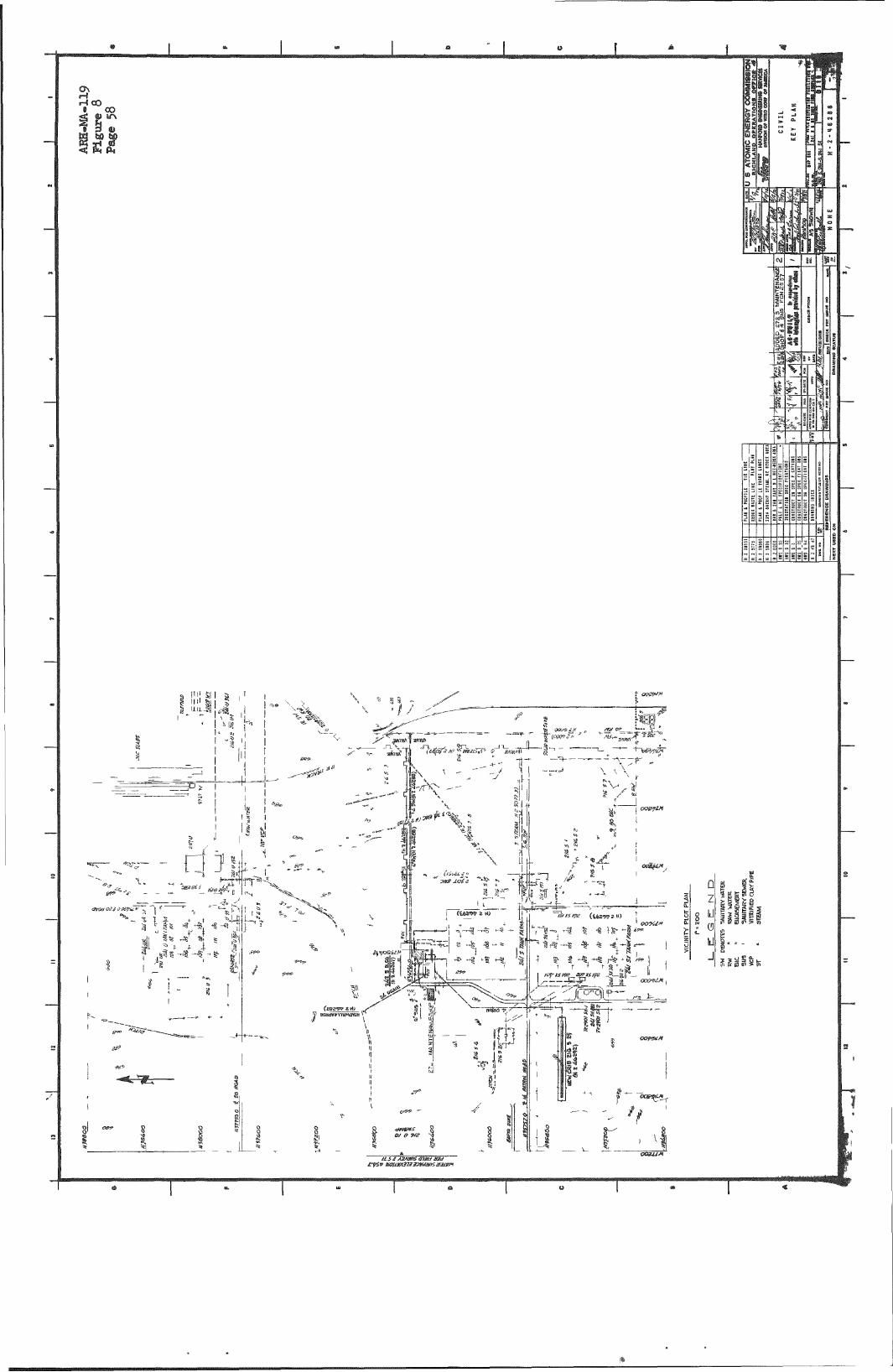
r-f 00
Si
/
• « « » «
-•q —
11 r
, •, 4 8 ' . . ^ OmiJM ^
^1^
I Is
ii iii
If
k
i s
If
i|i!i
i
il iilli
ssiilfe
if ' ' OOnsHM
t
r - i tn^ Nommiis
»


i
-^^-w
W^-. \
-Q—S-
I OIkIS JO ^S03
<3
a
- II J
u
] CD
,.^§=
| -
9
•of
( M [ | ^
01 f > ^ f^o
1 ^
-*^ JX
1^
<55" i A.
o •« >"
r L/t
.LU-"0"
-TF- - !l - ^
-^ j & ^
i l i:
^ ^ T^
-it
1 /
Y^^ •s ll 6<k I
SS
^M'
6^ C 61
s! ' i <
US
. _ = _ _ 1 .
m 111
^ ^ sy
e
f \
M s s
X • J
a
^J 6 El


I
ft l»lkl6Vte
' c A B . & . W l i l Y P . roB4) .CEM7ea«ON4 0i:PlPE-TVP.Fi»4 .a>R •i>"«l5i;<.2'304-l- %ST C T V P ) (5 EACH * )
r X ^ O
rsHavRMa<RADIUS6'.4'« UB0LT«;4 UUTS ^I'FRW.Ma-W?
'< l" MCKOLET
1' SPMUMeiRAEiySJ
itELTOY'.SW -
U K W - S B m M E U .
(A) S K i m t C r % T A ! _ L ^ ®(|
Lltf-IV-tf-SSKSBeOD-ESf AuYspsae
SHIELD IMG PLATES NO£CAI-E
DETAiL-g PIPE JUPPOBT OR GUIDE
P L * i N
DEIML n r.=ICA^4f DEmiLffl
TvacA"=-..#,.Pta£lS.
!-4'.V C0S.M8 SwaEDOED PIP.NS
EL 131 0 "

l - f
. < • «r"-
(-•f-
'i'V -<2 •3
-H2
IT 1: -I «.»
?i
00
IT,
]•
» I
-G
**?*"*• * 5 " J : . r t i
h ,1
4-^--
\ . > • •
; i
• <
ri-' • ' , • - «
• I
J
'rf-vt • 1 , ~ , -^1
F-mi
- \ I 1
_ _ . I
,-!
<C
..•1
•>'a
T
u u
Ob
3. £
o <r o
F
^ ^
^T*-,5-
-y-^
o
• ,
1 '£
I ^
J , c u
<» <
1 1 . ' 1 ' 1 " ' ' JL:^:JJ j U I < -^< J I < < 5 J
l i^ i 1 "\
\'. > IS.*
J.
o <o
, ! i 1 ! f « . 4 ^ * t * — * — .
o o
K | K
S-. iS- r
r 111
-4-4—
W I M I ' 9
1 1
^ an
111.
& C w • "
4*5
i
%ri ^
d a .
o
c l
5
^ m
o l o d> ^1
o
to
•J*
«JS
% o so
n
«T
S.I
«: w
J.
u
H
z

to Llk,Ot-*0-IL
tie'
i 1
T J T.'BFi,H£ET ;
ABH-m-119 Flgiire 14 Page 64
• ' - V
APPROVEDTOR^ONFORMANCE WITH DESIGN CRITERIA
BY / / . . A>-; ':'. ^ v J ' o 'V.^ , ,
- T - ^ TTK-
ȣ!i iJ-Ii
0 « 5
%.-,
T I E T':
'-',7 / / / V ^ /
W o r e - • INDICATEA T i l ffOC L . I . I . - ..i . N-T iwT -.K 8-3 i i jP=; i»~
V, ••v.. . V \
> J t
• ^ ' .
- ^ .
•r. V L i S i i , i ^
%
t-iSZ r t B E s J "X'. i t : r j i . . -i - if. ..u.. "P •- ~ r. •--•.• ' •-
"O- .. - i d .
- ; i T ^ t 3r R.£ IN
" ' * - ; . - ' ~ ; - * ~7t?v ,•:••'.• " - ^ ' < C ; * . .•/-v-:•• /*
• - ' • . : ' - " : : - - ; , ' - - > - : . f ^ : ^ v
. A.
\ . 55 CJJA i . - . P A C i ; (J. I *
1 i - - ,
YFOH THIS, fOINT (.jjVC* ISri
VIEV,' H H PKIM C.-/5 - l - 0 V - ^ n 1 l 1 C13
T 1
iio; R

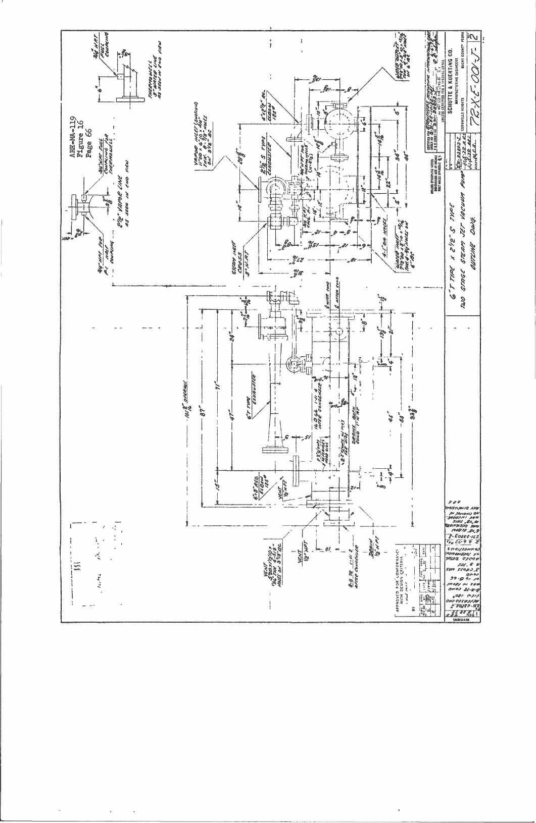
'Z^
}
't (w
^
fyidF^ k L^i
I mk-
^.**^
7-- '
•? ^ .
| 5
^» .
?» I r - ^
1
i I
l'%
1
J J..
\ , ' I 1
t . i ! ' H
? s ? «
I
4 "
4=:
.-:" - .-H^^
/ •"T
"C
"X" [
1 4. i? ^^ i.
l\
"TTXl
A 1. =! Ll L i ' ' E S . i_%Ua|—j
1 : eELXLJ
rr^eT-9 9"?
P9 -0 9^ j , ^ jnr^y fs fS'tr


PLAN
^ < ^ < ^ >i, '^^(^Qj®Qj £ o cj
REF £i.EV 66 / ~f
S£r PLAN
^^—\
ABH-MA-119 Figure 18 Page 68
^ v",)0 («>'
w 1.,..
DETAIL I i,CAL£ I/I I 0
%
i
c
1NOZZ NOSItE
A
B 1 c
0 » t
F G H
* J * 1^
» /. * M
N" ^ » P
P s r
u
V * w * X
Y * E
SaviCB
J < PIMP OUT 3 1 " o e coA/a 4" yessec vsur
STAri/s
NSW
NEW A/£W
£" SAA'Pii ff£n/3AAgX/ir f £" i PRSC CONQ 3 ; o^e^Pt. OK/ !• \ /USTB.
I<k i 2
! 2 ' oecON
" / 0/?<,AMC PO 1 M£ IV 2 ,K« (FltrnMliimi UliT
1 'Ii ; PRUEii COUO , 34, , Aa! TATOfi < \ PI QC CONO I ' Dl HIN i"
2 1 z
rii^p eieMFfjr
NiW i l l r
/£« / ^Ekr/'r&ufi ^iiu..i)\ v&ii'
3
4
4
DETAIL n SCALt I'lt 0
j£rt
m D£ iC R!P T1 ON
ASS e M B L Y(TK £ lOOj
rt-NK (eXHTINe,) SiS Non'i
& ISO'P P 5 0 FL&
& SCH 40i PIPS
I&-K0''PP BLIND PLC ASTMAISZ 104L isr
m FIAT SASffer ^/& THK
3 5CH^05 PIP£. ASTM Atll 304i Ssr
3 iso'ffp .5 o no- ASTMAISe 304L SST
l'ISO''K'P,i o ri.<r
I'scn 4CS P'lfi
I ISO'yiP 8L MO fCO- ASTA/I AI82,i04L $i7
l/li> THK
' ,30LT X 2 ' / i 16
rfvy H£X HUT
£ ISO 'PF eiMo ri'&
a PLAT ^Air(&T
' •sruo BOLT X 3 i n
/* V y H£ K N^T
I HALF COUPLJNH iCRD
I STJD BOLT 1 g ,
I f/VY Hi X NuT
•) sen -JOS P'PE
A ISO''PF SO Fte
1 sen 405 PIPS-
1 ISO* &P SC PLC
MATiKIAL
ASTM AlSi 304L SST
ASTM A312 3041 SST
Pi/PS TEFLJN
flStAfA2li i04L SST
Punt TSFLOU
AiTM Alii i3« S S
AiTM fll3<t iffSP
A$TPi Ai^e, 304L ssr
PUPS TiFLON
ASTi»Ai93 HP a a
(ISrMM94,SgS p
AiTui Aias 304L s s r
AiTM Alii •iH B S
AiTM Ai<}4 S/? SP
A t r w A?/2 $o^L s s r
A S « - A ( 8 2 » « s s r
AiTM A3'2 304-L SST
ASTM Alii SOUL i
DETAIL HI SCAie lA-l 0
bCALS ih 10
1 H!S DRAWING DETAILS THE ^OD!FtCAT10N OF AN tS!STING VESSEL R£FERENCF ORAWIt^g H 2 U0705
2 F A B S J C A T ON WELD SG LLtANihG AfiD TESTING OF STAINLESS STEEL SHALL BE N ACCORDANCE WiTH SPECIFICATION mZ 8S20 ISTAHDARO PROCESS SEFiVlCE)
DtTAIL 'SI SCALi I'A' 10
A ^
VESSEL SHALL BE HYDROSTATl CALLY TESTED BY FILLING #iTH ItjATER km APPLY !f.G 5 PS!G A R PRESSURE
PAIf^T VESSEL iOEt^TIFICATION 0!i FRONT USl^JG 2 H S G:) BLACK LETTERS ON
YELLOW BACK GROUtiD WITH SEf-51 GLOSS ALKYD ENAMEL PER FEDERAL SPECIFl
CATJOEJ TT E 539 B A^^PLiCATiON SHALL BE P£R MAHUFACTUPERS SPECIF I
CATION
FABR CAT ON TOLERANCES UNLESS OTHEPfelSE rJOTED SHALL BE
FRACTIONAL + \ 8
0

'-s u
" r . - -
1 f
L.oi-<a D o w e u
_ l '
SHORT O O W E L
Affl«M-119 Figure 19 Page 69
. ^ u i | ,
STUD HOLE
^, T O P
A..,.^- I THK C 3 \ / e R
CTBP
DOWEL HOLE
GENERAL NOTES I A L L M A T E R I A L . TO B E CARBON S T E E L A S T M - A 7
OR A S S E X C E P T AS NOTED
Z P A I N T A L U C A R B O N 3 T t E L vVITH ONE P R I M E COAT ^ T flO F I N I S H COATS A M E R C O A T 3 3
i-17/ /I _iL.ir-»- / ^ // "y / .?-•• /^ //-^TT-¥t
•Ik
p- ^ . tr-11
II
11 II II
- J i . _ .
fe
THK P L C S T L
f*
II
1
SHORT D O « £ L H - e - 5 7 3 3 | PT 2.
C A S K H - E - S e 3 8 6
_ i j . - , _ _
— LONto DOWe.1. H-Z-S7;33l fT" I M O D I F I E D )
STOO H «.-573S2 PT ^ (MOOl F l EDJ 2./
F R E E NUT H Z.-S23SS T f p e A ' a ;
F R E E N U T R E T A I N S R H-^-SI4•6 PT I (Zj
D O W E L S f S T U D S T o B E T H R E A D E D TO M A T C H T A P P E D H O L E S I N C A S K F i e L O C H E C K Ho l_6 L O C A T I O N S ^ T H R E A D (PS B U I L T ) u s e NO 3 F I T ON STUD THf^EADS IN CASK TO P K E V e N T S T J D 5 F P O M B A C K I N G OUT
APPROVED
2
POR W U C L E A R SAFETV
APPROVED BY DATE
SECTION A - A SECTION B - B
Hja S£38G WPR CASK
H £-3aS8S
m: v^m < S A ! — F T
VL 'FCM 01 5 9
5 8 9 0
U S ATOMIC ENERGY RigHLAI
MIC ENERGY COMMISSION
^enfiSICi rf@fif©r@ lia®iiip^ny
yODlFIED N PR
C A S K C O V E R
mr^'i^}^! T H-E-364aO

•
- H -
GEKJE^AL KJOTES I - DE>=l<i .Kj D A - r A . :
D E s i & N j P R E S s o e e OPSEfSH-TlMO. PKESSORE-•DESl&KJ TEMPSEATURS OPSCATIOC^ TrMPEISATUSe-COBEOi l OK) ALLOUJAtOte VOL.JMS
1-20 PS1& A-O P & I & I S O T 110° P. ' / I f c " 11-as, O.AU
EMPTY "SSOO** FULLY LCMMXD (2,9&0^
2 FABKICA-TlOfJ "SWAl-L MEET ESau iEEIMEKJTS O F A ' s M E CODS SECTS CIO ^ g a i I _ O i V \ Si 010 I
0 6 T A l U ^ ( T y P ) ^ ] ^ _^
Siire i n .
" US •! I
1_^ HHS EH
[ ; i flSHE SES V
3^assESEC »
g " l
J . 1
O . F l M A L P A ^ S OF= U f ^ ^ T C u O ^ U i g - g \ A ^ i S U C 5
EXIST lMsS. U^eCDIfOG (4x12)
SSAM D l f c H T O fT^ \ f p ^ ^ H E L L I f e . TOP OF " ^ \ S X
<I>Tn
.JSLO S^S i -O iK !<» ' s E A M
- P A I K I T I M G : a )AL l_ S K P O - ^ e t S L A K B O f o <S=TISEL S H ^ U L B E WARJb C UlTAfOEfe
PEIS. fePEC - S P £ 4 O ' V E S s j O N j p s a s s v i s ; ^ C O A T O F "SLl NJC C r t r e o i ^ l A , - T - E - P e i e F E D S I S A , - S P " S C T T - P - & < 4 . - ' 5 ' ^ T U J O ^ i V O i ' ^ H C O ' ^ T S i O F ' o e M 1 C^1.-0<3,S A t - K V D E K J A M E U F>ere F E o e i E i<=(t- • aP 'Cc^ . T r E S 2 0 - C L I ^ , U I & H T & i e A V C O L O E . . AF-P l - lC I ^ T I O K J •SrtAL.L B E PlEfS KAA!O^F"AC-T\.^IS(H ISS ^ ^ P e C 1 F l C A^TIOlO .
b) PAIKJT \ / H ^ ^ e u l O e i O T 1 F l C A T i OSO Ofo F^OPOT USiMO 2' H &H B J I - A C I - ^ 1„e-1—EISS ONJ Y^'- l -O-"- ' ©ACKC3.SOOIO&'.
- T O I _ c e A ( J C C ^ , J fOi .CSS OTHSeuJl-^C lOO-T e D •; ,4 B,i.l_ g s I ^EACTIOIUAL t ; 1%" A l O O 0 1 . A K . - S l ° - 0 '
NOZZLE UO.
M
3 '
3 "
3 "
/ z "
' / 2 '
/z"
3 "
oie.AiKj O U T
F I L L
PI
PI PC OUT
BbMOK-ED
C E A I M O U T
S A C K \A/ASH
KE-S l fO O U T
ABH-MA-119 Figure 20 Page TO
^ . - * -
^ ^ .
-S~ -a-^ VESSEl-
M O O K I T I M C J P A T T e i g . i o F o g . Pee r DETAIL.-ST H-2-4fcOAA
5 - V e ^ % G l _ - i H A L - l . PSS mvDEOSTATiCALLy T S S T E D A T I B O P%l<i. F o e O N j e H O O K .
g , - A E H C O a . u a > - l T Y A S S O R , A l > J C S -L e v E c r L , =. E l S < a 0 1 R . S D .
7 - u p p E e s c R . e e K j - s i f a V s O E . •504. V ^ S o K I S S H , l=>OR.-o - a S p T A ZOSA X.OIO"
a - Slfc -S/S CIS 3 0 * S/S , I 4-0 Kf l lCOOKJ ^ S T E O T OW, 1 0 0 MS&H E«JlVAl-S KOT s , B v A - c i . o o & E A D B n o s . e a o A L . -
3 - L . o v o s i e s c e s s s j s o p p o e - r - ^ i f c V ^ 012 30ao. s / s ^ M A T C R L I A L . T O 3 ^ -Col-JTi KJUOUS "bHCTIOfO U J I T H O L J T S 6 A M ^ ^ AL-L. eD<3»es T O SS C ^ I M P E O F l - A T /4." UOITMOOT AM-y S M A E P PEoTeL. i l OWS, P 0 E - O - % S . P T A iCe&A X 1-25" OP eSUAL.
i O - F C E E K 1 S T 1 I O & . - T A N J K T I - I A T l<» BElKSfa i M o o i F E D s e e ; H 2~&'5>BS"3 - lOILJ EX.CM COu - A S M ^ DET H-2- i i .° ! S i O - l O U SXCH c o l . - StiT f OST,
JTAtoC^SfOT
E K i ^ . T i t o s i ^xleL.Dl^o&. S E A M - D i S H TO s n e - i - i . -p^^
ELEVATIOf^ /\-A
( ! >
•
. . ASSEMBLY I S ^ M O W W iio P L A K J
view ^ secTioi>j ii-e
bECTIQN £-& Foe OISiEWTATlffM s N u y SCREEW5 N O T •Si-tOWU
«
lOtO £>iCH COL,- D E T A I L S g440« lOM £XCH COL.-TSST-ft.L.'i
«Z4i;04J lOM EKCH COL -D6TA1LS
ffry
AK
AR
feO
fcO
4 4
M
24
M.
AR
12
13
14 IS
17
2o
2 i
12 Zi ?4 25
Zfc
27
28
29 So
3 l
3Z 33
35 3fe
37 3«
4 0
41
£L 4 3
4 5
47
1 1 DESCR.IPT- |Ob4
A> 'S>5=SK^BL.y
S H E L L . P L A T E
FIAMSED { D19IID HIAB a 0>^ lA^'THICK > P.-A-aME-
Dl 'bTfeie.UTIOKl PLATE. DETAIL H?-4«>44.
FLANGE, S ' - I S O " S.O. E F
FLAMCS, 8" - IBO" S O, E p.
D E T A I L rt-2-4.i»OA2
DETAIL H-2-4&OAZ
3 0 4 L -
P I P E , :
P I P E , 3 " •SCH 4 - 0
C O L J P L I K J O . yi".^c>od •5CH.E
D E T A I L H 2 - A ( ^ O A 2 .
R i M f c
U P P E R • s C e e E M fJEF H-2-Afco«.0
,-LAUGE^ A 9 ' - I ' Z S ' " L I & H T TYPS S O .
O A l . K e T . y OSXAIL hl-S--^&D4.2
GMKET, 7y/'0 O .t Sft, I P K/e T « t i i & ' B ° C ^
• B A K , J ' V / ^ "
B A E ,
6 A B 2 X ' / 4 . "
OSTPilL i-l .g-.^&04.3 B I W &
S P A C F E B A R , 1'/^'*^%'^ ! /»
LOMJEE sc resEU E E F I4-Z-4K.040
LOWEE SCBEEM juPpogr j |
B O L T , 1/2" i 3 u t o c - 2 A x. z " L O K J C
L O C K L U A S H E ( B _ / J . " l i T D
^ O L T . i ! / t . - & U I ^ J C - 2 A K A " L w f O O
U U T I ' / i - fcOkJC-ZB
G A S K E T , 5'5>i."i>.0 « A B " | O «. ' /B"THK-,
B'.>LT ! - 1C5 UIOC S A ii: £ " L O t O O
L O C I - C lAJASHEE., • % ^ " * T D
U J I C e . 16 O A
I t . , TE, y s "K4-"xc - -R. g /a 'V^ < & "
3 K 3 K s/a"
eA.a ye" >
M A T ' L O S R i p
A ' ^ T M - A . 3 C .
C - S - T L .
A % T M - A t B I
1= — £3=.
C - S T L ^B A ' b T ^ / l - A l O f e
T L 0 ( ^ I a
A-5.TK^-A.ae.
SEE N O T 6 7
?5t%llSs CODE i 9 0 0 O E EQUAL
— e T ^ = F C A i T M _ - A 3 & .
^ 0 4 L - % » T - A 7 7 f a
AfcTK/l r K ^ - A 3 i
Ct,seG-l G,»WL» -
sre (JoTE- s
S6S NOTE 9 P 6 - T < a . . L
H - a - A f o o a S , A^-rM_^AI^3
^ i ^ S l ^ l f - A 1 ^ 3 ^ " * ^ i T ^
A « . T ^ A - ^ 3 t
AS-TK^-A-gS,
AJTMSTS
D I -71 ^
U. S. ATOMIC ENERGY COMMISSION
ION EXCHANGE COLUMN
rx-D-i ASSEMBLY t. PETAILS-
'H-2-4&04- I 2 5 0 0
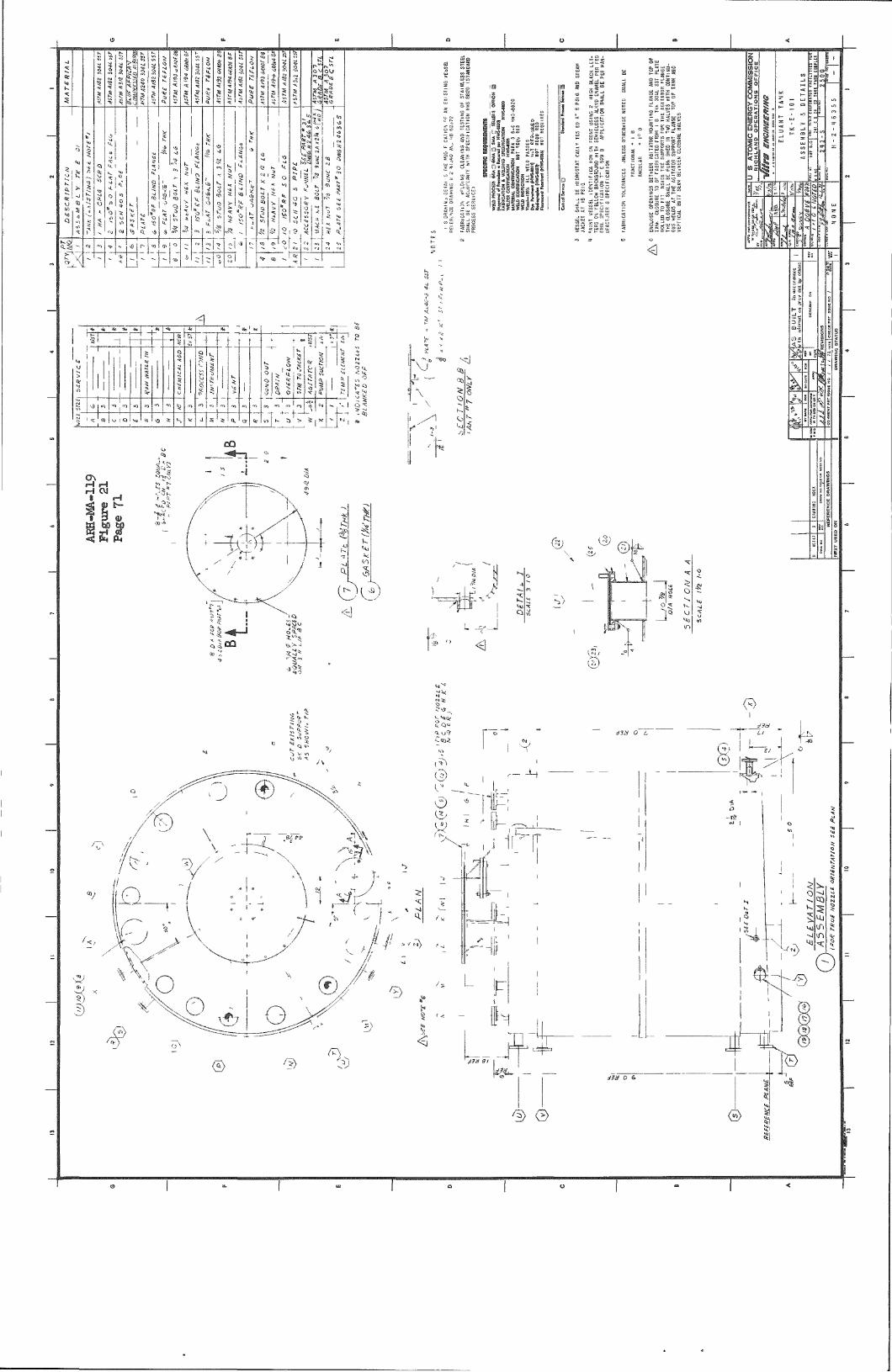
xf
npT
TT
! 2
fl I ^
1} S 5 |
at ••M
\S''i
i
O
I
I B i
i i i B m
S5»
3° S o ssea
- g a s
MM
m
I a iiili
S SdSH
0
I. i I
l.i "
« ^
III r t
h
> 1 Of 1
s
% ^ % ^ Ttej , a
I I „, j.
Ml
^ j-o 1
i J
1 1 1 r
T) or,
1
i 1
1 1 1
5-"o fo r^
"y ' u 1 1
* , M
j r »
s i s S?lj
Ml
^ " sp
^ If r ^ ^ ' *s
^ 1 i Q
i 4
. 1.
L 1
1
s l =
— r — „ , i
J
>
t i Q.
1
O" *
' ^ ; t - s 1 ? :
O
Q
o
en
s
1 J J . K 3 >
t
t
1 i o j
* r
1
*
1 a.
-r-J
5.4.
^1
V "OK
m
_, 4-,J-
;?>
I-. • ^
a
V *
^ L. k i V 10
v
<i
^ "* 1 i ^ kr""" i> i\ ^ ',1
/ u
qji
03
I-.
j j
§
^
-
''^=^^
11 . /
•sa
I I
<1
CSi ^ ©kL
u,5
^
^|i 5
O
\
I

is' [MI
Isl i
*
5 ^
^ * « <
S 5 ' fe 5
o ^5
* I I ;
>|,
J:" i: « >j Q ki
I I I j
< O
- J , 5 |
"«:
K' Q ^ \_
(E>- I \ -]
I ni
J 1
"5 S5
U gli
i i s 3 3
!i i f ^ s
SSI
si
i;:}i
:p g
„ t
iiiii 5 g "
I ;°S" i
^ on. ^ ^
i i .
0
r7
1. c^
1 » -i
a I f —
_ _
— f 'S
O
1
^
- V )
" l^ X • ^
0.
r
!«,
r.i^
"^ r
i ^ 1 ilil
i • |
Pi?
^ &
- H
•I
il
"I
-I? 1
1 n-1 1
^ .
/ ^ \
^
1 K i<^
e
c)
-si
I
©
R1


m^Cii/RCZi/RC^-l
~£ -ijowiQ ncZ'i
€) ^ INTERLOCK FOR R-C-3 SXST6M
j iR5B IN- EBLOCK SEQUENCE SEE H-1-46M7) i TVP}
Am-MA-.119 Figure 2k Page 71
^ ; ! HTER.OCK rOR R - C - l SYSTEM SOR ISTERLOCK SESUEWCe
s e e H - ' j - 4 & % 7 i )
K6/KCZMCi.> •.oW rE EC2-I
DETAIL H I
T
..J
SYMBOL
FIO
FL
PH4N
PSC
RW-IP
L E G E N D
DEFINITION
FIOVI i»DIC«TOR 1NTE6I1»I0R
Fi J * LI«E«P1ZES
PILSE HEIGHT Ai|fiLY2ER
PROPORTiOML SAMPLE CONTROL
RAOUTIOH AMPLIFIER
•liPUTIi) M7(1!C2) /2"C& 777 M - | a C S )
X
SAMPLE- FLOW
MONITOR A S S E M E ^
^ • F I L T E R
RESULATOR
SPARSE . TUBE A
RESTRlCTiWO -S Y - F A S S
PROPORTIONAL — SAVIPLER PCS
n LAS
SAMPLS
«,,^
"^^
a
- 1 ^ 7 — - - ,
J -
^ 2 ' - P C - 5 5 4 . M42(SCS> , , I I r N / l» -URW-lfcOO M5 V P t J I I I 1 •
Morg- I moTe fiSR RC3 SVSTSM ONtV. \ MAGNETIC f l i lWMEIEI i n>SRCZ$ysritA see | M u s t BL«J F U L L r
OSTAILSC —I (80ITOM a TWP)
^MA&Wu..L^I
I
ELECTRIC SOLEKOID VALVE - S WAV
ELECTRIC SOLENOID VALVE - 3 BAY
FOR ADDiTIOIIAL .E6END SEE MABISSS p r-msm » n-2-w325
FOR StEMLWIARV SLt H i *3.fo^5fe
SF£ DETAIL m
DETAIL I
MOTE: SMOIA^W F o a R.C-3 RaOi^TlOW M O M T O R
<EXCSFT ASU©T€0>
3'PC-S58-M4 2
-A.
DIVERTED n o w
3 H;-SS7-M4a
ISJSRMAl FLOW
DETAIL-m
US2JU. S. ATOMIC ENERGY COMMISSION Is,'. 1^' _gllgMl.Al«ID_OPE«ATION3 OFFICE 4
INSTRUMENT ENSINEERING FLOI OliG^AM
SanPLING.H0NITORIH6 5 ^ 3 g f ^ ^ SanPLING. HONITORIH6 il^-f-r.',., "gf » 0IVE8SI0H D H E 8 4 H S
H - 2 - H 6 3 3 I

ii
St
Ss
is
h i f
4^
Hi :
| A
SD&feil
C ^
•^ I
L-ii
4s]
^
!~Mii 5
I
: ^ 3 5 :
3
•J y|
SSJ WHS« L
iC-
iii
I ^tie' ^ l i '
^51 f=l, ^;„i
II
h
11^ ijlil V^ I -
L ® -
^ , I
S t
\vsrr'*!„v"T S-^Y-^ I
MiliSp"
in
u i
> . ! P i s
Rik
#11 5 I ' 3-
zn LOU sv.i
-A.^|)—Ccqi-
zm 9011 s» , i ,
3i go B 5
fliOl ---{2|>'Hxx}--
(•i>~|
.) IXfl r< Z.W ioi.1 SV.1- '
^ -A^^ •^Xh
7?
€'-"-#- iig -lih -tm- T
H§h KXI .
SW n i l SV ZijI
-T—^Cd ^
€>~n
•-7 [X3] (^g