Embed Size (px)
Citation preview

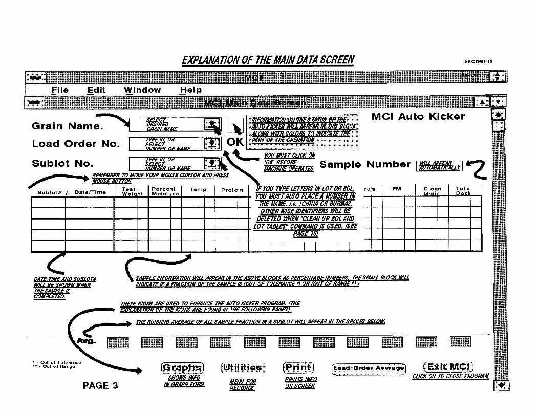
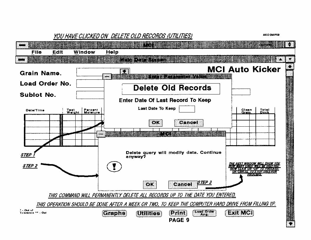
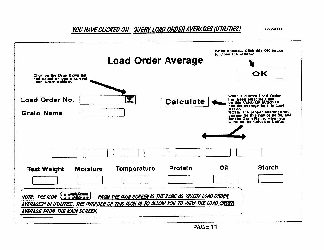
MCi AutoKicker
Mid-Continent Industries, Inc.
AutoKicker/Grain Tester Operations/Application Users Guide
Designed by Glenn Wells Darren Wells Steve Wells
Of MCII
Newton, Kansas
Copyright 1996 Mid-Continent Industries, Inc.

MCII License Agreement – (Proof of License) This license Agreement is your proof of license. Please treat it as a valuable property. This is a legal Agreement between you (either an individual or an entity) and Mid-Continent Industries, Inc. (MCII). By accepting this software package and/or by using the Software, you agree to be bound by the terms of this Agreement. If you do not agree to the terms of this Agreement promptly return the disks and accompanying items (including printed materials and binders or other containers) to MCII at 1801 SE 9th ST. Box 563, Newton, KS 67114.
MCII Software License 1.GRANT OF LICENSE. This MCII License Agreement (“License”) permits you to use one copy of the specified version of the MCII software product identified as the MCII Auto Kicker/Grain Tester Application, which may include user documentation provided in “online” or electronic form (SOFTWARE”), on any single computer, provided the SOFTWARE is in use on only one computer at any time. If you have multiple licenses for the computer when it is loaded into the temporary memory (i.e., RAM) or installed into the permanent memory (e.g., hard disk, CD-ROM, or other storage device) of that computer and that computer is connected to the Grain Analyzer. If the anticipated number of users of the SOFTWARE will exceed the number of applicable Licenses, then you must have a reasonable mechanism or process in place to ensure that the number of persons using the SOFTWARE concurrently does not exceed the number of Licenses. 2.UPGRADES. If the SOFTWARE is an upgrade from another product, whether form MCII or another supplier; you may use of transfer the SOFTWARE only in conjunction with the upgraded product, unless you destroy it. The SOFTWARE may be transferred only as a package and according the License Agreement. 3.COPYRIGHT. The SOFTWARE (including any images, “applets,” photographs, animation’s, video, audio, music and text incorporated into the SOFTWARE) is owned by MCII or its suppliers and is protected by United States copyright laws and international treaty provisions. Therefore, you must treat the SOFTWARE like any other copyrighted material (e.g. a book or musical recording) except that you may either (a) make one copy of the SOFTWARE solely for backup or archival purposes, or (b) transfer the SOFTWARE to a single hard disk provided you keep the original solely for backup or archival purposes. You may not copy the printed materials accompanying the SOFTWARE, no print copies of any user documentation provided in “online: or electronic form. 4. OTHER RESTRICTIONS. This License is your proof of license to exercise the rights granted herein and must be retained by you. You may not rent or lease the SOFTWARE, but you may transfer your rights under this License on a permanent basis provided you transfer this License, the SOFTWARE, and all accompanying printed material, retain no copies, and the recipient agrees to the terms of the License. You may not reverse engineer, decompile or disassemble the SOFTWARE, except to the extent that the foregoing restriction is expressly prohibited by applicable law. 5. DUAL-MEDIA SOFTWARE. You may receive the SOFTWARE in more than on media. Regardless of the type or size of media you receive, you may use only the media appropriate for your single designated computer or network server. You may not use the media on any other computer or computer network, or loan, rent, lease, or transfer them to another user except as part of a permanent transfer (as provided above) or other use expressly permitted by this License.
Limited Warranty LIMITED WARRENTY. MCII warrants that the SOFTWARE will perform substantially in accordance with the accompanying printed materials for a period of ninety (90) days from the date of receipt. Any implied warranties on the SOFTWARE are limited to ninety (90) days. Some states/jurisdictions do not allow limitations on duration of an implied warranty, so the above limitation may not apply to you. CUSTOMER REMEDIES. MCII’s entire liability and your exclusive remedy shall be, at MCII’s option, either (a) return the price paid or (b) repair or replacement of the SOFTWARE that does not meet MCII’s Limited Warranty and that is returned to MCII with a copy of your receipt. This limited Warranty is void if failure of the SOFTWARE has resulted from accident, abuse, or misapplication. Any replacement SOFTWARE will be warranted for the remainder of the original warranty period or thirty (30) days, whichever is longer. Outside the United States, neither these remedies nor any product support services offered by MCII are available without proof of purchase from an authorized no-US source. NO OTHER WARRANTIES. To the extent permitted by applicable law, MCII disclaims all other warranties, either expressed or implied, including by not limited to implied warranties of merchantability and fitness for a particular purpose, with respect to the SOFTWARE, the accompanying written materials, and any accompany hardware. This limited warranty gives you specific legal rights. You may have others, which vary from state/jurisdiction to state/jurisdiction. NO LIABILITY FOR CONSEQUENTIAL DAMAGES. To the maximum extent permitted by applicable law, in no event shall MCII or its suppliers by liable for any damages whatsoever (including, without limitation, damages for loss of business profits, business interruption, loss of business information, or other pecuniary loss) arising out of the use or inability to use the MCII product, event if MCII has been advised of the possibility of such damages. Because some states/jurisdictions do not allow the exclusion or limitation of liability for consequential or incidental damages, the above limitation may not apply to you.

Users Guide Information in this document is subject to change without notice and does not represent a commitment on the part of MCII. The software and/or databases described in this documentation are furnished under license agreement of nondisclosure agreement. The software and/or databases may be used or copied only in accordance with the terms of the agreement. It is against the law to copy the software on any medium except a specifically allowed in the license or nondisclosure agreement. No part of this document may be reproduced or transmitted in any form or by any means, electronic or mechanical, including photocopying, recording, or information storage and retrieval systems, for any purpose other than the purchaser’s personal use, without the express written permission of MCII. Companies, names and data used in examples herein are fictitious unless otherwise noted. Copyright 1996 MCII. All rights reserved.
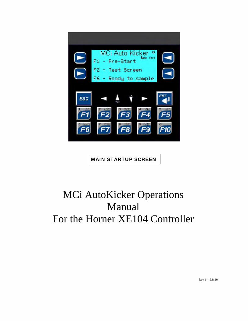
MAIN STARTUP SCREEN MCi AutoKicker Operations
Manual For the Horner XE104 Controller
Rev 1 – 2.8.10

1
Table of Contents Quick Startup Instructions .................................................................................................................................. 2 Controller OFF/ON Screens ................................................................................................................................ 3 Scale Alarm............................................................................................................................................................ 4 Main Startup Screen............................................................................................................................................. 4 Prestart Screen ...................................................................................................................................................... 5Test Screen............................................................................................................................................................. 5 Scale Readout Screen............................................................................................................................................ 6 Test I/O Screen .................................................................................................................................................... 7 Choose Mode Screen........................................................................................................................................... 8 Mode Start Screen............................................................................................................................................... 8 Waiting on PC Screen......................................................................................................................................... 9 Password Entry Screen....................................................................................................................................... 9 Setup Screen ........................................................................................................................................................ 10 Timer Selection Screen ....................................................................................................................................... 10 Order Setup Screen............................................................................................................................................. 11 PC Communication Screen ................................................................................................................................ 12 Scale Type Selection Screen ............................................................................................................................... 13 Machine in Operation Screen ............................................................................................................................ 14 Weight Monitoring Screen ................................................................................................................................. 14

Quick Startup Instructions
Note: this section is what you would normally do as a power up routine. The further pages are generally reserved for trouble shooting or technical service, but are included for reference.
2. Press F6 for “Ready to Sample”
Press the F6 button to go to the Choose Mode Screen
1. Power on the Controller
2
Now go to the PC and perform the rest of the steps to start sampling........
OFF ON
Co g ntroller shown in the ON position. Notice the testinand passed display flash through.
XExxx Self Test
3. Press F1 for “Choose Mode”
Press the “F1” button, as long as it has been setup for PC (default). See note>>>>>
NOTE: If modifications have been made, and the unit is to operate with a PC, then you must choose a Mode that has been setup for PC Use. The PC will send the proper command to change to the mode that matches the grain, according to the Grain Setup in the PC program.
5. Ready for the PC command......... 4. Press F1 for “Start”
Press the F1 button to place the unit in the ready mode

3
Controller OFF/ON Screens
Note: the following pages will not show the full image of the controller. Please notice the highlighted buttons and functions.
OFF ON
Controller shown in the OFF position. Turn the switch to the ON position to begin.
XExxx Self Test Passed
OFF ON
Controller shown in the ON position. Notice the testing and passed display flash through.

4
Scale Alarm
Main Startup Screen
Press One of the 3 buttons for the function. F1- Pre-start Mach. Runs ONLY the Shaker Unit for a set period of time, and dumps all hoppers. Beneficial for sieve changes or partial samples. F2- Test Screen Allows for testing I/O as well as a Scale Test F6- Ready to Sample. This is for normal sampling operations. The next screen will be Choose Mode
Press the F6 button to retry scale functionality
This screen will appear if there is a problem with the gram scale on startup.
If the Scale has a problem communicating, or if the power cord is unplugged, this screen will appear. Check the communication cable and power cord to insure they are connected properly. Also, if factory settings have been restored on the scale, it will need to be set correctly. Contact Mid-Continent Industries, Inc.
Press the F1 button to run the shaker unit through a “dry run”. Once complete, it will return back to this screen.
Press the F6 button to go to the Choose Mode Screen
OFF ON
Press the F2 button to see the scale readout or test Inputs/Outputs

Prestart Screen
Press the F7 button to stop and go back to the ‘Main Startup’ Screen immediately, or just wait until it is finished.
F1 button has been pressed from the Main Start Screen. This screen appears, and will stay until the prestart process is either complete or interrupted. Once completed, it will return automatically to the Main Start Screen.
Test Screen
Press the F1 button to test the operation of the gram scale.
F2 button has been pressed from the ‘Main Startup’ Screen
Press the F7 button to return to the ‘Main Startup’ Screen
Press the F3 button to check the I/O operation. This test is normally used for mechanical troubleshooting purposes only.
5
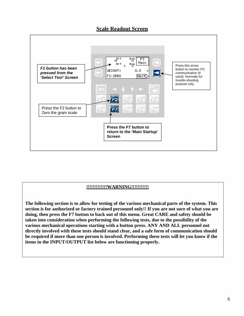
Scale Readout Screen
Press the F2 button to Zero the gram scale
Press this arrow button to monitor PC communication (if used). Normally for trouble-shooting purpose only.
F1 button has been pressed from the ‘Select Test’ Screen
Press the F7 button to return to the ‘Main Startup’ Screen
!!!!!!!!!!!!!WARNING!!!!!!!!!!! The following section is to allow for testing of the various mechanical parts of the system. This section is for authorized or factory trained personnel only!! If you are not sure of what you are doing, then press the F7 button to back out of this menu. Great CARE and safety should be taken into consideration when performing the following tests, due to the possibility of the various mechanical operations starting with a button press. ANY AND ALL personnel not directly involved with these tests should stand clear, and a safe form of communication should be required if more than one person is involved. Performing these tests will let you know if the items in the INPUT/OUTPUT list below are functioning properly.
6

Test I/O Screen
F3 button has been pressed from the ‘Select Test’ Screen
Small Up/Down buttons move through I/O’s, then press the ENT button to accept the selection
Press the F7 button to return to the ‘Main Startup’ Screen
Press the F2 button for I/O OFF
Press the F1 button for I/O ON
Press the ENT button to accept the selection. Now use the F1/On F2/Off functions.
This section of the screen will change to the I/O name as you arrow through the selections
7
*..
1. -12VDC IS USED AS "COMMON" THRU-OUT THE SYSTEM ON 12VDC DEVICES. +12VDC IS USED IN SWITCHING DEVICES ON OR OFF.2. #13 & #14, OF VALVE BOX, GO EITHER TO 12VDC MOTOR STARTERS OR TO 12VDC LATCHING RELAYS THAT START REGULAR AC VOLTAGE STARTERS.3. INLET SENSOR IS WIRED WITH BROWN TO +12VDC; BLUE TO -12VDC; BLACK PIN 12 FOR SIGNAL. 4. CONVEYOR RELAY IS REMOVED AND WIRED AS SHOWN ON SCHEMATICS MARKED '0WIREAK2' AND '9720WIRE'.5. SPLITTER RELAY IS WIRED AS SHOWN ON SCHEMATIC MARKED '9705WIRE' WITH PIN 7 ON RELAY SOCKET WIRED TO -12VDC AND PIN 2 WIRED TO BYPASS SWITCH IN VALVE BOX THEN TO +12VDC.ALL OTHER DEVICES WIRED TO -12VDC, IN VALVE BOX, WITH +12VDC FROM CONTROLLER TERMINALSUSED AS SWITCHING.
Q14 VAC. PUMP
+12VDC (FROM 12VDC P.S.)
-12VDC (FROM 12VDC P.S.)
BARRIER TERM. STRIP
(TO CONTROLLER AND 12VDC P.S.)
120VAC LINE (FUSED 1 AMP) (TO CONTROLLER AND 12VDC P.S. VIA FRONT PANEL SWITCH)
120VAC NEU
Q15 KICKER
Q16 SAMPLER
(CONTROLLER BOX)
*
Q10 PROTEIN DIVERTER
I1 READY TO SAMPLE
Q13 CONVEYOR TIMER
Q8 CLEAN
Q9 THRU'S
Q11 B. DIVERTER
I2 FILL SENSOR
Q3 INLET HOPPER
TERMINAL BOARD
Q4 ASPIRATION
Q5 OVERS
CONTROLLER BOX
Q6 SB
Q7 FM
13 VAC. PUMP
CONV. 120VAC LINE-
FOR MOTOR STARTERS AND CONV. MOTOR CONTROLFOR MOTOR STARTERS
CHANGED VAC SENSOR TOCONVEYOR TIMER1-25-99 SDW
HORN_IO3REV. 2-3-10 DDW
UPDATED I/O #'S. 2-18-10 SDWUPDATED FOR 12VDC TEXT. 3-25-10 SDW
IN
OUT
14 KICKER
+12 VDC
-12 VDC
PUMP MOTOR
KICKER MOTOR
120VAC NEU-
120VAC LINE-
FOR CONV. MOTOR CONTROL
TO MOTORSFROM STARTERS
120VAC LINE120VAC NEU
BARRIER TERM. STRIP
10 READY TO SAMPLE
7 PROTEIN DIVERTER
5 CLEAN
11 CONVEYOR TIMER
6 THRU'S
8 B. DIVERTER
12 FILL SEN
VALVE BOX
0 INLET HOPPER
1 ASP
3 SB
4 FM
2 OVERS
(ALSO M.T. INLET)

Choose Mode Screen
If you are finished with testing, then you would press the F6 button from the main MCi AutoKicker screen, and it would bring you here. In normal operation, once you have powered on the unit, you would press the F6 button to start with, then choose one of the buttons here, then F1 for Start, which would bring you to ‘Waiting on PC’, and that would be the end. That is Four steps: Power On, press F6, Press a Mode, then press F1 to Start and be ready for the command from the PC.
Press one of the five “F” buttons for the chosen Mode (1-5)
F6 button has been pressed from the ‘Main Startup’ Screen
Press the F7 button to return to the ‘Main Startup’ Screen
Mode Start Screen
Press the F1 button to begin sampling. If the PC Mode = YES has been selected, ‘Waiting on PC” is displayed. See below for more.
Press the F3 button to edit timer settings, etc.
F1 button has been pressed from the ‘Choose Mode’ Screen
Press the F7 button to return to the ‘Choose Mode’ Screen
8
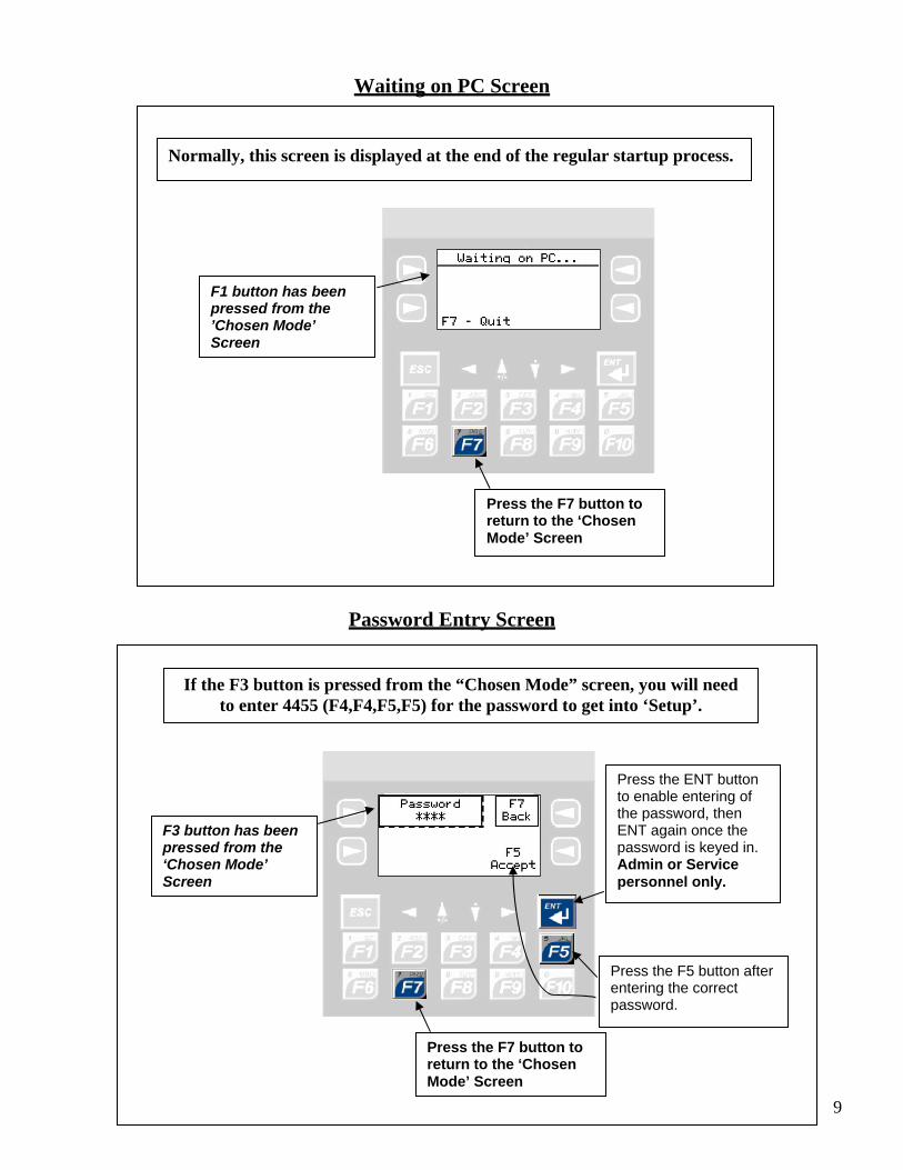
Waiting on PC Screen
Normally, this screen is displayed at the end of the regular startup process.
Press the F7 button to return to the ‘Chosen Mode’ Screen
F1 button has been pressed from the ’Chosen Mode’ Screen
Password Entry Screen
9
If the F3 button is pressed from the “Chosen Mode” screen, you will need to enter 4455 (F4,F4,F5,F5) for the password to get into ‘Setup’.
Press the F5 button after entering the correct password.
Press the ENT button to enable entering of the password, then ENT again once the password is keyed in. Admin or Service personnel only.
F3 button has been pressed from the ‘Chosen Mode’ Screen
Press the F7 button to return to the ‘Chosen Mode’ Screen
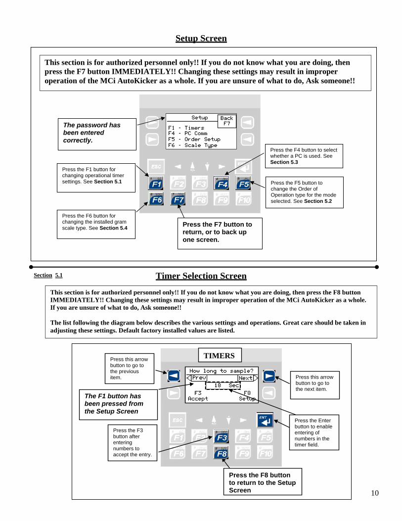
Setup Screen
This section is for authorized personnel only!! If you do not know what you are doing, then press the F7 button IMMEDIATELY!! Changing these settings may result in improper operation of the MCi AutoKicker as a whole. If you are unsure of what to do, Ask someone!!
Press the F1 button for changing operational timer settings. See Section 5.1 Press the F5 button to
change the Order of Operation type for the mode selected. See Section 5.2
Press the F7 button to return, or to back up one screen.
The password has been entered correctly.
Press the F4 button to select whether a PC is used. See Section 5.3
Press the F6 button for changing the installed gram scale type. See Section 5.4
Timer Selection Screen Section 5.1
10
This section is for authorized personnel only!! If you do not know what you are doing, then press the F8 button IMMEDIATELY!! Changing these settings may result in improper operation of the MCi AutoKicker as a whole. If you are unsure of what to do, Ask someone!! The list following the diagram below describes the various settings and operations. Great care should be taken in adjusting these settings. Default factory installed values are listed.
The F1 button has been pressed from the Setup Screen
Press the F8 button to return to the Setup Screen
Press the F3 button after entering numbers to accept the entry.
Press this arrow button to go to the next item.
Press this arrow button to go to the previous item.
Press the Enter button to enable entering of numbers in the timer field.
TIMERS

Section 5.1 cont
11
3. Press the F3 button after changing the Order to accept the entry.
Press the F8 button to return to the Setup Screen
1. Press the ENT button to enable changing of the Order.
2. Use these Up/Down arrows to change the Order, then press the ENT button, then F3
ORDER SETUP
F5 button has been pressed from the Setup Screen
Order Setup Screen
Item Selection Mode 1 Mode 2 Mode 3 Mode 4 Mode 5
How long to sample? 1 1 1 1 1 Fill Sensor Override 6 6 6 6 6 Screen Cleaning Time 10 10 10 10 10 Fill Hopper Open 18 18 18 18 18 Gate 1 Open Time 2 2 2 2 2 Gate 2 Open Time 2 2 2 2 2 Gate 3 Open Time 2 2 2 2 2 Gate 4 Open Time 2 2 2 2 2 Gate 5 Open Time 2 2 2 2 2 Gate 6 Open Time 2 2 2 2 2 Next sample delay 3 3 3 3 3 When to Sample One of 3 One of 3 One of 3 One of 3 One of 3 Protein Analyzer One of 3 One of 3 One of 3 One of 3 One of 3
The Timers settings listed below may be modified, but can distinctly affect the behavior of the MCi AutoKicker as a whole. Some of the settings are listed as “or”, and are set according to the facility requirements. They are shown in the table below primarily as a reference. Setting explanations: All times are in seconds How long to sample?: How long to operate an external sampling system Fill Sensor override: If there is a “Ready to Sample” input, but not enough grain, go ahead and do a cycle after the timer runs out Screen Cleaning Time: Once the weigh scale stabilizes, run the shaker for these many seconds, then stop Fill Hopper Time: How long to keep the main inlet hopper open to allow for all grain to enter where needed, including a moisture tester (if installed) Gate(s) 1 – 6 Open Time: How long to keep the sample separation hopper s open to allow the material to pass Next sample delay: How many seconds to wait before starting another sample cycle. When to Sample: One of 3 selections. Automatically after dumping the Fill hopper (After Fill Hpr), Automatically after a completed sample (After Sample), or Manually after each sample by button press or PC command (Manual Start) Protein Analyzer: One of 3 selections: Send a command to operate a protein analyzer on a unit with a bottom diverter (PA- Yes with B-Div), Send the command without bottom diverter (PA- Yes w/o B-Div), or do not send a command at all (PA- NO)
Section 5.2

Section 5.2 cont
Item Selection Mode 1 Mode 2 Mode 3 Mode 4 Mode 5
Order 1 or 4 2 3 5 5
The Order and PC settings listed below may be modified, but can distinctly affect the behavior of the MCi AutoKicker as a whole. Some of the settings are listed as “or”, and are set according to the facility requirements. They are shown in the table below primarily as a reference. Setting explanations: Order 1: Dumps all sample fractional hoppers (Gates 1-5) together on the weigh scale, then dumps the sample out (Gate 6). Order 1 is normally used with all grains that do not require a clean grain test weight. It is usually selected to be matched with Mode 1. It only sends one command to the moisture tester to get moisture, temperature, and test weight, whereas Orders 2 and 3 send out two commands to operate the moisture tester. See below. Order 2: Dumps each fractional hopper into the weigh scale, then dumps each fraction out. Order 2 is normally used with all grains that DO require a clean grain test weight. It is usually selected to be matched with Mode 2, and is normally used if the desired process is to not put any fractions together. Order 2 is useful for divisional capture of each fraction. Order 2 MUST have a bottom diverter and clean grain conveyor as part of the installed system, takes the longest amount of time to process a sample, and is rarely used. It also sends out two commands to operate the moisture tester, one to get the moisture and temperature, one to get the clean test weight. Order 3: Dumps the broken grain into the weigh hopper with the clean grain, then dumps that out through a bottom diverter and into the clean grain conveyor to be elevated to the moisture tester and optional protein analyzer. The remainder of the sample fractions are then dumped and weighed individually, then dumped out together through the other side of the bottom diverter, away from the clean grain conveyor. Order 3 MUST have a bottom diverter and clean grain conveyor as part of the installed system. Order 3 also sends out 2 commands to operate the moisture tester, one to get the moisture and temperature and one to get the dockage/fm free test weight. Orders 2 and 3 can also be configured to use the optional protein analyzer (PA- Yes with B-Div) Order 4: Similar to Order 1, only there are two Gates, 3 and 4 that do nothing. As with Order 1, all sample fractional hoppers (Gates 1, 2 and 5) dump and weigh individually on the weigh scale, then dumped out together as one (Gate 6). Order 4 is normally used for coarse grains that do not need as many fractional weights, such as Corn, and do not require a clean grain test weight. It is usually selected to be matched with Mode 1. Normally used with Corn or Sorghum Ethanol production. It only sends one command to the moisture tester to get moisture, temperature, and test weight, and can be configured for the optional protein analyzer (PA- Yes w/o B-Div).
PC Communication Screen
Section 5.3
PC COMM
Press the F8 button to return to the Setup Screen
1. Press the ENT button to enable changing of the setting.
F4 button has been pressed from the Setup Screen
3. Press the F3 button after changing the selection to accept the change
2. Use these Up/Down arrows to change the setting, then press the ENT button, then F3
12

13
Item Selection Mode 1 Mode 2 Mode 3 Mode 4 Mode 5
P.C. Configuration PC is Used PC is Used PC is Used PC is Used PC is Used
Section 5.3 cont
Note: The PC configuration is default to “PC is Used” on ALL Modes. If the setting is changed to “No PC Used”, then the unit will start without the PC by pressing the ‘F1 – Start’ button from the Chosen Mode screen, but the Moisture Tester or Protein Analyzer will not operate. These devices require the use of the PC for their remote commands. They can be operated with their buttons, but the PC program should be exited while doing this.
Section 5.4
Scale Type Selection Screen
SCALE TYPE
Press the F8 button to return to the Setup Screen
THIS SHOULD ONLY BE MODIFIED BY AN AUTHORIZED SERVICE PERSON!!!! CHANGING THIS WILL CAUSE THE MACHINE TO MALFUNCTION!!!! PRESS THE F8 BUTTON TO RETURN TO THE SETUP SCREEN IMMEDIATELY!!!!!!!!!!!!!!

Machine in Operation Screen
Once the machine has started to process a sample, this screen is displayed, and the indicated line will change according to the current process. This is useful for confirmation and change of a running process.
This line will change
Weight Monitoring Screen
14
You can monitor the weight capture be pressing the F8 button during a sample process. This is useful for confirmation of the weighing processes. The screen may switch back to the “Machine in operation” screen from time to time, or by pressing the F8 button again. Pressing the F6 button will cause the system to stop after the current sample process.
Press the F8 button to return to the “Machine in operation” screen, then again to come back here
These numbers will change during a sample weighing process

NOTES
15


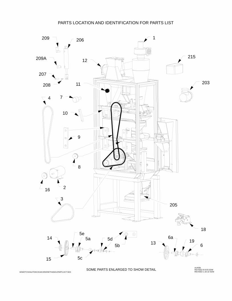
MCi AUTO KICKER PARTS LIST ITEM DESCRIPTION PART NUMBER 1 Aspirator Fan 4 Inch 41-5142 2 Drive Motor ½ HP/120 Volt 41-5135 3 Drive Belt/Motor 41-5275 4 Drive Belt/Scalp 41-5270 5a Shaker Mount Bearing (2 required) 41-5240 5b Pitman Bearing (2 required) 41-5245 5c Pitman Crank Assm 41-4805 5d Pitman Drive Bar UHMW (3/4” thick) 41-4809AK 5e Shaker Drive Shaft 41-4804 6 Scalp Drive Bearing (2 required) 41-5240 6a Scalp Drive Shaft 41-4815 7 Cam Roller 41-5235 8 Idler/Drive Belt 41-5340 9 Shaker Pivot Arm (UHMW) 41-4820 10 Scalp Pivot Arm (UHMW) 41-4819 11 Feeder Adjusting Knob 41-5145 12 Air Damper Assy. 4-Screen 41-4032A 13 Pulley/Scalp Shaft Driven 41-5255 14 Pulley/Scalp Lower Drive 41-5250 15 Pulley/Shaker Lower Shaft Driven 41-5260 16 Pulley/Drive Motor 41-5265 18 Door & Screen Clamp 50-7295 19 Scalp Cam and Shaft Assembly 41-5335 203 Vacuum Pump/ New Style 50-7105 204 Motor Vacuum Pump 1/2HP, 120 Volt (old style) 50-7155 205 Digital Weighing Scale 50-7300 206 Vacuum Cyl. 1 1/16" Dia. (7 used, includes fittings) 50-7230 207 1 1/16 Cylinder Clevis & Pin 50-7245 208 Clevis Pin Keeper 50-7246 209 Vacuum Fitting - Elbow 50-7185 209A Vacuum Fitting - Straight 50-7190 215 Power Supply for Aspirator Fan 50-7126 220 Vacuum Pump Drive Coupler (old style) 50-7133 300 Balls/Cleaning (72 required) 41-5195 newpartdiaAK.doc
Revised 6/17-11 ddw
16 2
3
1
12
203
215
205
5c
5b14
15
PARTS LOCATION AND IDENTIFICATION FOR PARTS LIST
SOME PARTS ENLARGED TO SHOW DETAIL
206209
209A
208
4
8
10
7
11
A1400bREVISED 8-9-05 DDWREVISED 1-20-10 SDWWSKETCH2\AUTOKICK\AKVIEWS\ETHANOL\PARTLOCT.SKD
9
5d5a6
196a
13
207
185e

27
MCi KICKER/AUTOKICKER FOUR SCREEN CHART SCREEN SIZES, LOCATION, FEED, AND AIR SETTING(S) – REAR DAMPER
SCREEN LOCATION SCALP SECOND THIRD FOURTH FEED AIR Wheat JGS Blank NH 4 x 1/2 5 RD 2 5 *7 12 RD 5 RD NH 10 TRI 4 x 1/2 Barley (Feed) 9 x 3/4 6 RD NH 4.5 x 1/2 10 TRI 2 5 *1 9 TRI NH 5 x 3/4 6 RD Corn 32 RD Blank NH 12 RD 8 RD 3 1/2 1 *2 36 RD 14 RD Blank or 6 RD Soybeans 24 RD 8 RD NH 10 x 3/4 12 RD 3 1/2 1 *6 26 RD Blank NH 8 or 9 x 3/4 10 or 11 RD, Blank Corn/Soy Combo 32 RD 8 RD NH 24 RD 12 RD 3 1/2 1 * for Splits separation 10 or 9 x 3/4 10 or 11 RD Sorghum 12 RD Blank NH 4 x 1/2 5 RD 2 5 *5 9 x 3/4 5 RD NH 10 TRI 2.5 RD Oats 9 x 3/4 5 RD NH 4 x 1/2 10 TRI 2 1/2 6 *4 10 x 3/4 8 TRI NH 5 RD Millet 12 RD Blank NH 9 RD .067 RD 1 6 *3 6 x 3/4 10 TRI NH 4 x 1/2 Flower “O” 18 RD Blank NH 12 RD 8 RD 2 1/2 6 *8 5 x 3/4 10 TRI Flower “C” 24 RD 12 RD NH 22 RD 20 RD 3 1/2 6 *9 28 RD 14 RD NH 20 RD 18 RD Canola #000 Riddle Blank NH .064 x 3/8 3/64 x 3/8 1 6 Flax #000 Riddle Blank NH .064 x 3/8 4.5 RD 1 1/2 6 * JGS 5 RD NH 4 x 1/2 (.0625) 5 RD Safflower 15 RD Blank NH 6 x 3/4 10 TRI 2 5 MCi Auto Kicker for Fuel Grains Corn 32 RD 12 RD Blank Any 3 1/2 1 Soybeans 24 RD 8 RD NH 10 x 3/4 Blank 3 1/2 1 Sorghum 12 RD 5 RD NH 4 x 1/2 Blank 2 5 Corn/Sorg Combo 12 RD 5 RD NH Blank Any 3 4 * 4 x 1/2 Blank *Optional screen sizes are on the second row below the grain name. Optional 3rd & 4th screens can be placed in SECOND slot, if handle is removed, to obtain desired results. NH stands for NO HANDLE.
The AIR setting is only a guide. Depending on the test weight of the grain, it may need to be opened more or less. To increase the air takeout, CLOSE the damper more.
NOTICE: Recommendation for screens used in the MCi KICKER are based upon extensive lab work and verification of users. The suggested screens allow the fastest and most accurate method to achieve the fairest results. According to FGIS, almost any method may be used by “commercial” grain handlers to achieve Results Comparable to Official Standards. MCi AUTOKICKER screen selections may not be the same as the MCi KICKER, due to its inability of hand picking. You should check the results of your machine with your local official testing station, then adjust the feed, screen sizes, and the air setting to obtain results comparable. Multiple machines in the same company should be checked with one another for consistent results across the local area. Mid-Continent Industries, Inc. will not be held liable for the results obtained from any grain grading process. Operators, installation locations, firmness of the floor it is placed on, etc., will affect results. *1 Dockage is the total fractions of air, scalpings, and through 6 RD. *6 10 x 3/4 is used the most. FM is everything through FM is anything else left in the sample after process. the 8 RD and everything other than Soybeans. NOTE: To
match the 3-Screen Kicker, use a Blank where indicated. *2 BC is everything through the 12 RD & over an 8 or 6 RD *7 Dockage is the total fractions of air, scalpings, FM is thru the 8 or 6 RD and everything other than Corn. and through the 5 RD. SB is through the 4 x 1/2. *3 Dockage is everything other than Millet. FM is anything else left in the sample after process. *4 FM is through 5 RD and everything other than Oats. *8 5 RD will take out less. *5 Only for competitor comparison, and should not be necessary. *9 Confectionary Sunflowers can be sized as well as other *6 Splits can be checked with an 8, 9, or 10 x 3/4 slotted. grains. Word\manual\newkicker\new-rd4screenset.doc Revised 3/29/11 ddw

FOUR SCREEN MCI KICKER/AUTOKICKER
REMOVE HANDLEINSERT OPEN END
MID CONTINENT INDUSTRIES INC.NEWTON KS. 67114 PH. 316-283-9648
**
AIR SETTING 5
2
10 TRI
4 X 1/2
NOTE!: When screens are inthe Optional array, then the bottom panis Small and Broken Grain and thethird pan is Dockage if it's contentsis over 50% weed seed !!!!!!!!
WSKETCH2\KICKER\SCREEN_B\4WHEAT
5 RD
4 X 1/2
Blank
**
5 RD
JGS 12 RD
WHEAT

FOUR SCREEN MCI KICKER/AUTOKICKER
NEWTON KS. 67114 PH. 316-283-9648MID CONTINENT INDUSTRIES INC.
AIR SETTING 5
2
9 TRI NH
WSKETCH2\KICKER\SCREEN_B\4BARLEY
5 X 3/4
6 RD NH
10 TRI
4.5 X 1/2
6 RD
9 X 3/4

FOUR SCREEN MCI KICKER/AUTOKICKER
NEWTON KS. 67114 PH. 316-283-9648MID CONTINENT INDUSTRIES INC.
AIR SETTING 1
3 1/2
- FM is all material Scalped, Aspirated, through 8 RD, and not Corn that remains in the processed sample.- BC is what falls through the 12 RD and stays on top of the 8 RD.- BCFM is BC and FM combined, including hand picked FM.- Test Weight is determined on uncleaned sample.
8 RD NHBlank NH
8 RD
12 RD
Blank6 RD
14 RD
WSKETCH2\KICKER\SCREEN_B\4CORN
32 RD 36 RD

CORN: = BC SOYBEANS: = Material may include small beans, so DO NOT combine theentire pan amount with TOTAL FM.Hand pick the FM from this pan, adding that FM to the top pan and scale for TOTAL FM. This process is to reduce the amount of hand picking necessary for Soybeans.
NOTE: NOT RECOMMENDED FOR USE IN THE MCI AUTOKICKER!!
FOUR SCREEN MCI KICKER
NEWTON KS. 67114 PH. 316-283-9648MID CONTINENT INDUSTRIES INC.
AIR SETTING 1
3 1/2
8 RD NH
12 RD
24 RD
11 RD
WSKETCH2\KICKER\SCREEN_B\4corn_bn
32 RD

FOUR SCREEN MCI KICKER/AUTOKICKER
NEWTON KS. 67114 PH. 316-283-9648MID CONTINENT INDUSTRIES INC.
AIR SETTING 5
2
10 TRI
2.5 RD
WSKETCH2\KICKER\SCREEN_B\4SORGHUM
5 RD NHBlank NH
4 X 1/2
5 RD
9 X 3/412 RD

FOUR SCREEN MCI KICKER/AUTOKICKER
NEWTON KS. 67114 PH. 316-283-9648MID CONTINENT INDUSTRIES INC.
AIR SETTING 6
2 1/218 RD
WSKETCH2\KICKER\SCREEN_B\4oflower
8 RD
Blank NH
12 RD
10 TRI
5 X 3/4

FOUR SCREEN MCI KICKER/AUTOKICKER
This is for Order 4 in the MCi AutoKicker, which DOES NOT dumpthe 2 bottom hoppers to decrease sample process time. The 8 RD isonly to keep the sieve cleaning balls in place. This setup could alsobe used on a regular MCi Kicker if the 8 RD FM separation was not necessary.
MID CONTINENT INDUSTRIES INC.NEWTON KS. 67114 PH. 316-283-9648
AIR SETTING 1
3 1/2
14 RD NH12 RD NH
8 RD
Blank
WSKETCH2\KICKER\SCREEN_B\4CORNETH
32 RD 36 RD

FOUR SCREEN MCI AUTOKICKER ONLY
NOTE: THIS AUTOKICKER CONFIGURATION IS USED FOR FUEL GRAINS.REFER TO THE STANDARD KICKER CHART FOR THAT DIAGRAM.
MID CONTINENT INDUSTRIES INC.NEWTON KS. 67114 PH. 316-283-9648
AIR SETTING 4
312 RD Corn Clean - Sorghum FM
* Blank - Corn FM - Sorghum BK
* 4 X 1/2 - Corn FM - Sorghum Clean
FM - Both Grains5 RD NH
Blank
Any


![OUTH OF OTTER LAKE - Ontario · MCI C MCI] MCI. MCI: MCI'! SUIPH-FOOTAGE FROM 74.7 73.7 77.35 84.2 87.03 110.0 109.35 TO 75.8 73.9 77. 4^ 84.3 87.17 110. If 109.4; TOTAL see at see](https://img.pdfslide.us/doc/110x75/5ecb988006364b24ec1cdd84/outh-of-otter-lake-mci-c-mci-mci-mci-mci-suiph-footage-from-747-737-7735.jpg)