Embed Size (px)
Citation preview
CardioQuip Modular Cooler Heater
Operator/Service Manual
Model MCH-1000
Cardiopulmonary Bypass Temperature Controller
P/N 1000-05-1177 Publication date: November 30, 2016
© Copyright 2016 CardioQuip, LP. All rights reserved.
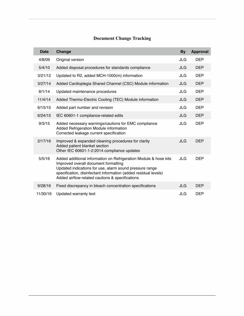
Document Change Tracking
Date Change By Approval
4/8/09 Original version JLG DEP
5/4/10 Added disposal procedures for standards compliance JLG DEP
3/21/12 Updated to R2, added MCH-1000(m) information JLG DEP
3/27/14 Added Cardioplegia Shared Channel (CSC) Module information JLG DEP
8/1/14 Updated maintenance procedures JLG DEP
11/4/14 Added Thermo-Electric Cooling (TEC) Module information JLG DEP
6/15/15 Added part number and revision JLG DEP
6/24/15 IEC 60601-1 compliance-related edits JLG DEP
9/3/15 Added necessary warnings/cautions for EMC complianceAdded Refrigeration Module informationCorrected leakage current specification
JLG DEP
2/17/16 Improved & expanded cleaning procedures for clarityAdded patient blanket sectionOther IEC 60601-1-2:2014 compliance updates
JLG DEP
5/5/16 Added additional information on Refrigeration Module & hose kitsImproved overall document formattingUpdated indications for use, alarm sound pressure range specification, disinfectant information (added residual levels)Added airflow-related cautions & specifications
JLG DEP
9/28/16 Fixed discrepancy in bleach concentration specifications JLG DEP
11/30/16 Updated warranty text JLG DEP
CardioQuip Modular Cooler-Heater Operator/Service Manual Page 1
CardioQuip Modular Cooler Heater Operator/Service Manual
Model MCH-1000 Cardiopulmonary Bypass Temperature Controller
Notices
The information in this document may change without notice. CardioQuip makes no warranty of any kind regarding this material including, but not limited to, the implied warranty of merchantability and fitness for a particular purpose. CardioQuip cannot be held liable for errors herein or for consequential damages concerning the use of this material.
CardioQuip reserves the right to make equipment changes and improvements which may not be reflected in this manual. Online support resources, including the latest version of this manual, may be accessed at http://www.cardioquip.com/MCH/Support.html.
This document may not be reproduced in whole or in part, as it contains proprietary information. Such information may not be disclosed to others for any purpose or used for manufacturing purposes without written permission from CardioQuip. Reproduction or storage of this material in electronic media without the express written permission of CardioQuip is prohibited.
Manufacturer’s Responsibility
CardioQuip may consider itself responsible for any effect on the safety, reliability and performance of the equipment if and only if:
• Repairs, adjustments, modifications or retrofit are performed by authorized CardioQuip service personnel
• The device is used according to the instructions set forth in this manual • The electrical service and connections comply with relevant electrical codes
For assistance, call 888-267-6700 (in the U.S.) or +1 979-691-0202 (international).
© Copyright 2016 CardioQuip, LP. All rights reserved.
Page CardioQuip Modular Cooler-Heater Operator/Service Manual2
Table of ContentsGeneral Information 4 ...................................................................................................
Introduction 4 ..................................................................................................................Indications for Use 4 .......................................................................................................Expected Service Life 4 ....................................................................................................Warnings and Precautions 5 ............................................................................................Manual Conventions 6 .....................................................................................................Device Labeling 6 ............................................................................................................Specifications 7 ................................................................................................................Obtaining Service 7 .........................................................................................................Contact Information 7 .....................................................................................................Limited Warranty 8 ..........................................................................................................Storage 9 ..........................................................................................................................Transportation 9 ..............................................................................................................Lifting 9 ...........................................................................................................................
Overview 10 ....................................................................................................................MCH-1000(i) Hardware Overview 10 .............................................................................MCH-1000(m) Hardware Overview 11 ...........................................................................Operation Overview 11 ....................................................................................................Add Ice! 11 .......................................................................................................................
Control Screens 12 ..........................................................................................................Note: When the Refrigeration Module is installed, the tank should be filled to the tops of the chiller plates. 12 ........................................................................................................System Test 13 ..................................................................................................................Standby 14 .......................................................................................................................Priming 15 .......................................................................................................................Settings 16 ........................................................................................................................Run 17 ..............................................................................................................................
Alarms 18 ........................................................................................................................Low Water Level (medium priority) 18 ............................................................................Low Ice (low priority) 19 .................................................................................................Overtemp (medium priority) 19 .......................................................................................System Failure (medium priority) 20 ...............................................................................Audio Silence 20 ..............................................................................................................
Setting the Temperature 21 ...........................................................................................
Connectors, Valves, & Hoses 22 ....................................................................................Main Hose Connectors 22 ...............................................................................................Cardioplegia Hose Connectors 23 ..................................................................................Internal Recirculation Valve 23 .......................................................................................Blanket Hose Connectors 24 ...........................................................................................System Drain 25 ...............................................................................................................Tank Drain 25 ..................................................................................................................
CardioQuip Modular Cooler-Heater Operator/Service Manual Page 3
Hose Kits 26 ....................................................................................................................Standard Hose Kit 26 ............................................................................................................Dripless Anti-Microbial Hose Kit 26 ....................................................................................Custom Hose Kits 26 .............................................................................................................
Tank Lid Anchor Knobs 27 ..............................................................................................
Patient Blankets 27 .........................................................................................................
Optional Cooling Modules 29 ........................................................................................Thermo-Electric Cooling (TEC) Module 29 ....................................................................
Installation 29 ........................................................................................................................Maintenance 29 .....................................................................................................................
Refrigeration Module 30 .................................................................................................Installation 30 ........................................................................................................................Operation 30 ..........................................................................................................................Maintenance 30 .....................................................................................................................Storage 30 ..............................................................................................................................
MCH Operation 32 .........................................................................................................Unpacking 32 ...................................................................................................................Physical Inspection 32 .....................................................................................................Initial Operation Check 32 ..............................................................................................
MCH-1000(i) Control Module Check 33 ..............................................................................Basic Function Test 34 ..........................................................................................................Temperature Control System Test 34 ....................................................................................Alarm Tests 34 .......................................................................................................................Terminating Operation 35 .....................................................................................................Leakage Current Test 35 ........................................................................................................Initial Cleaning 35 .................................................................................................................
Normal Operation 36 ......................................................................................................High Temperature Alarm 38 ............................................................................................A Note About Flow 38 ......................................................................................................
Maintenance 39 ...............................................................................................................Water Quality 39 ..............................................................................................................Disinfectants and Cleaners 39 .........................................................................................After Every Use 40 ...........................................................................................................Weekly 40 .........................................................................................................................Quarterly 40 ....................................................................................................................Annually 41 ......................................................................................................................Disposal Procedures 41 ...................................................................................................
Troubleshooting 42 .........................................................................................................Wiring Schematics 44 ......................................................................................................
Annual Preventive Maintenance Checklist 46.............................................................
Page CardioQuip Modular Cooler-Heater Operator/Service Manual4
General Information
Introduction
The CardioQuip Modular Cooler-Heater (MCH) brings easy and accurate temperature control to the operating room. The latest touchscreen technology offers fast, user-friendly, multi-language device control. Redundant software and hardware failsafes ensure patient safety. A combination of audible and visual alerts enable effective monitoring without undue distraction. Conscientious design declutters the perfusionist’s work area to allow more workspace. Thanks to intelligent features such as self priming, automatic defrost, and patent-pending Adaptive Temperature Control™ technology, the MCH requires significantly less operator intervention than traditional cooler-heaters, giving the perfusionist more time for patient care.
Indications for Use
The CardioQuip Modular Cooler-Heater (MCH) is indicated to supply temperature-controlled water to heat exchange devices (e.g.; Cardiopulmonary Bypass Heat Exchangers) to help control a patient’s temperature during extracorporeal circulatory support and/or thermal regulation procedures lasting not longer than six hours.
The MCH is intended to be operated by, or under the supervision of, a qualified perfusionist. This device is not designed, sold or intended for use except as indicated. While there are no known contraindications, use of the MCH for purposes other than those indicated places responsibility for performance and results with the user.
Expected Service Life
The MCH, when properly maintained and operated according to these instructions, should provide at least ten years of reliable service in a typical hospital environment.
CardioQuip Modular Cooler-Heater Operator/Service Manual Page 5
Warnings and Precautions
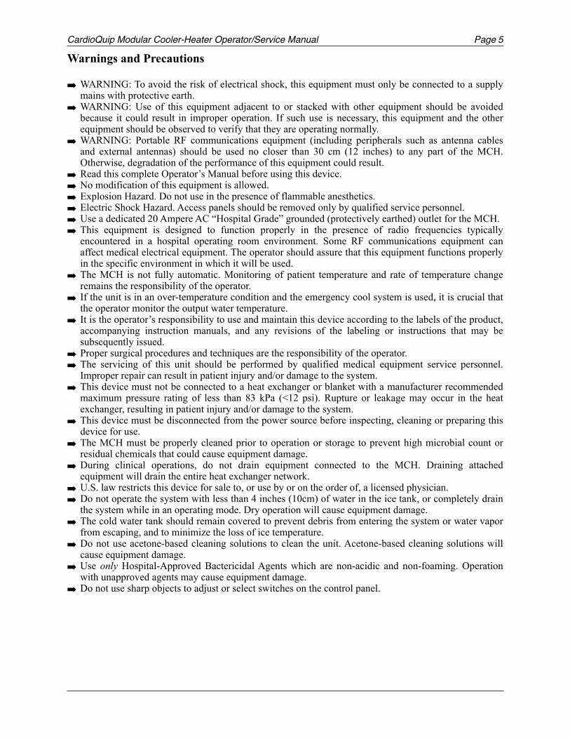
WARNING: To avoid the risk of electrical shock, this equipment must only be connected to a supply mains with protective earth.
WARNING: Use of this equipment adjacent to or stacked with other equipment should be avoided because it could result in improper operation. If such use is necessary, this equipment and the other equipment should be observed to verify that they are operating normally.
WARNING: Portable RF communications equipment (including peripherals such as antenna cables and external antennas) should be used no closer than 30 cm (12 inches) to any part of the MCH. Otherwise, degradation of the performance of this equipment could result.
Read this complete Operator’s Manual before using this device. No modification of this equipment is allowed. Explosion Hazard. Do not use in the presence of flammable anesthetics. Electric Shock Hazard. Access panels should be removed only by qualified service personnel. Use a dedicated 20 Ampere AC “Hospital Grade” grounded (protectively earthed) outlet for the MCH. This equipment is designed to function properly in the presence of radio frequencies typically
encountered in a hospital operating room environment. Some RF communications equipment can affect medical electrical equipment. The operator should assure that this equipment functions properly in the specific environment in which it will be used.
The MCH is not fully automatic. Monitoring of patient temperature and rate of temperature change remains the responsibility of the operator.
If the unit is in an over-temperature condition and the emergency cool system is used, it is crucial that the operator monitor the output water temperature.
It is the operator’s responsibility to use and maintain this device according to the labels of the product, accompanying instruction manuals, and any revisions of the labeling or instructions that may be subsequently issued.
Proper surgical procedures and techniques are the responsibility of the operator. The servicing of this unit should be performed by qualified medical equipment service personnel.
Improper repair can result in patient injury and/or damage to the system. This device must not be connected to a heat exchanger or blanket with a manufacturer recommended
maximum pressure rating of less than 83 kPa (<12 psi). Rupture or leakage may occur in the heat exchanger, resulting in patient injury and/or damage to the system.
This device must be disconnected from the power source before inspecting, cleaning or preparing this device for use.
The MCH must be properly cleaned prior to operation or storage to prevent high microbial count or residual chemicals that could cause equipment damage.
During clinical operations, do not drain equipment connected to the MCH. Draining attached equipment will drain the entire heat exchanger network.
U.S. law restricts this device for sale to, or use by or on the order of, a licensed physician. Do not operate the system with less than 4 inches (10cm) of water in the ice tank, or completely drain
the system while in an operating mode. Dry operation will cause equipment damage. The cold water tank should remain covered to prevent debris from entering the system or water vapor
from escaping, and to minimize the loss of ice temperature. Do not use acetone-based cleaning solutions to clean the unit. Acetone-based cleaning solutions will
cause equipment damage. Use only Hospital-Approved Bactericidal Agents which are non-acidic and non-foaming. Operation
with unapproved agents may cause equipment damage. Do not use sharp objects to adjust or select switches on the control panel.

Page CardioQuip Modular Cooler-Heater Operator/Service Manual6
Manual Conventions
This Operator’s Manual uses the international alert symbol ! to indicate critical safety and operational information. The alert symbol followed by a WARNING denotes an instruction or procedure which, if not carried out correctly, may result in injury to the technician, the patient or other personnel. The alert symbol followed by a CAUTION denotes an instruction or procedure which, if not carried out correctly, may damage the MCH or connected equipment.
Device Labeling
This symbol indicates that the device is Type BF medical equipment per IEC601.1
This symbol indicates that conductors carrying high voltage are nearby.
This symbol indicates that consultation of documentation is critical to safe operation.
This symbol indicates that the device requires an alternating supply current.
This symbol is located near chassis grounding locations to indicate protective earth ground.
This symbol indicates manufacturer information.
This symbol indicates the connection point for the Control Unit.
This diagram shows the operation of the tank and system drains.
This symbol indicates the mains power switch for the refrigeration system.
!
3. General: Electricity and electronics- 50 -
Pile ou accumulateur, symbole général
Pour marquer un dispositif concernant l'alimentation d'un appareil au moyen de piles ou d'accumulateurs, par exemple un bouton de vérification des piles, l'emplacement des bornes du connecteur, etc.Note 1 - Pour marquer la fonction contrôle des piles, l'emploi du symbole 5546 est recommandé.Note 2 - Le symbole n'est pas destiné à être utilisé pour indiquer la polarité.
Battery, general
To identify a device related to the supply of equipment by means of a (primary or secondary) battery, for instance a battery test button, the location of the connector terminals, etc.Note 1 - To identify a battery check function, the use of symbol 5546 is recommended.Note 2 - This symbol is not intended to be used to indicate polarity.
On battery powered equipment.Sur un matériel alimenté par pile ou accumulateur.
5001
Position des piles ou accumulateurs
Pour marquer le boîtier lui-même et pour marquer le positionnement des éléments à l'intérieur.
Positioning of cell
To identify the battery holder itself and to identify the positioning of the cell(s) inside the battery holder.
On and in battery holders.Sur un boîtier de pile ou accumulateur, et à l'intérieur du boîtier.
5002
Contrôle de pile ou d'accumulateur
Pour marquer la commande permettant de vérifier l'état d'une pile ou d'une batterie (d'accumulateurs) ou pour marquer le voyant de vérification de l'état de ce matériel.Note - Selon l'état de la pile, la surface de la zone noircie peut varier.
Battery check
To identify a control to check the condition of a (primary or secondary) battery or to identify the battery condition indicator.Note - According to the condition of the battery, the size of the darkened area may vary.
5546
Élément rechargeable
Pour marquer un matériel qui ne doit être utilisé qu'avec des éléments rechargeables ou identifier ces éléments. Lorsqu'il figure sur un boîtier, le symbole indique également le positionnement des éléments.
Rechargeable battery
To identify equipment which shall only be used with rechargeable (secondary) cells or batteries, or to identify rechargeable cells or batteries. When shown on a battery holder, the symbol also indicates the positioning of the cells.
5639
Terre
Pour marquer une borne de terre dans les cas où l'utilisation du symbole 5018 et du symbole 5019 n'est pas explicitement recommandée.
Earth (ground)
To identify an earth (ground) terminal in cases where neither the symbol 5018 nor 5019 is explicitly required.
5017
Terre de protection
Pour marquer les bornes destinées à être raccordées à un conducteur de protection extérieur contre les chocs électriques en cas de défaut d'isolement, ou pour marquer la borne de la terre de protection.
Protective earth (ground)
To identify any terminal which is intended for connection to an external conductor for protection against electric shock in case of a fault, or the terminal of a protective earth (ground) electrode.
5019
Terre sans bruit
Pour marquer les bornes d'une terre sans bruit, par exemple d'une installation de terre spécialement conçue pour ne pas provoquer un fonctionnement défectueux de l'équipement.
Noiseless (clean) earth (ground)
To identify a noiseless (clean) earth (ground) terminal, e.g. of a specially designed earthing (grounding) system to avoid causing malfunction of the equipment.
5018
!
!
!
3. General: Electricity and electronics- 49 -
5.3 General: Electricity and electronics
Énergie électrique
Pour indiquer toute source susceptible de fournir de l'électricité et la mise en oeuvre (ou l'arret) de la production ou de l'utilisation d'énergie électrique.
Electric energy
To signify any source of electric energy, for example on devices starting or stopping the production or use of electric energy.
0232
Plus; polarité positive
Pour marquer les bornes positives d'un matériel fonctionnant en courant continu ou produisant du courant continu.Note - La signification de ce symbole graphique dépend de son orientation.
Plus; positive polarity
To identify the positive terminal(s) of equipment which is used with, or generates direct current.
Note - The meaning of this graphical symbol depends upon its orientation.
5005
Moins; polarité négative
Pour marquer les bornes négatives d'un matériel fonctionnant en courant continu ou produisant du courant continu.Note - La signification de ce symbole graphique dépend de son orientation.
Minus; negative polarity
To identify the negative terminal(s) of equipment which is used with, or generates direct current.
Note - The meaning of this graphical symbol depends upon its orientation.
5006
Courant continu
Pour indiquer sur la plaque signalétique que l'appareil ne doit être alimenté qu'en courant continu; pour marquer les bornes correspondantes.
Direct current
To indicate on the rating plate that the equipment is suitable for direct current only; to identify relevant terminals.
5031
Courant alternatif
Pour indiquer sur la plaque signalétique que l'appareil ne doit être alimenté qu'en courant alternatif; pour marquer les bornes correspondantes.
Alternating current
To indicate on the rating plate that the equipment is suitable for alternating current only; to identify relevant terminals.
5032
Courant alternatif triphasé
Pour indiquer sur la plaque signalétique que l'appareil ne doit être alimenté qu'en courant alternatif triphasé; pour marquer les bornes correspondantes.
Three phase alternating current
To indicate on the rating plate that the equipment is suitable for three phase alternating current only; to identify relevant terminals.
5032-1
Courant alternatif triphasé neutre
Pour indiquer sur la plaque signalétique que l'appareil ne doit être alimenté qu'en courant alternatif triphasé neutre; pour marquer les bornes correspondantes.
Three phase alternating current with neutral conductor
To indicate on the rating plate that the equipment is suitable for three phase alternating current with neutral conductor only; to identify relevant terminals.
5032-2
Courant continu et alternatif
Pour indiquer sur la plaque signalétique que l'appareil peut être alimenté indifféremment en courant continu ou en courant alternatif (tous courants); pour marquer les bornes correspondantes.
Both direct and alternating current
To indicate on the rating plate that the equipment is suitable for both direct and alternating current (universal); to identify relevant terminals.
5033
!
!
8. Safety signs- 70 -
Défense d’utiliser en zone résidentielle Not to be used in residential areasSafety 16
IEC 60878 Note:This safety sign is under consideration for standardization in ISO 3864.
Défense de pousser Pushing prohibitedSafety 34
IEC 60878 Note:This safety sign is under consideration for standardization in ISO 3864.
Défense de s’asseoir Sitting prohibitedSafety 35
IEC 60878 Note:This safety sign is under consideration for standardization in ISO 3864.
Défense de franchir Stepping prohibitedSafety 37
IEC 60878 Note:This safety sign is under consideration for standardization in ISO 3864.
Défense de charger Loading prohibitedSafety 36
IEC 60878 Note:This safety sign is under consideration for standardization in ISO 3864.
Avertissement général, attention, risque de danger
General warning, caution, risk of dangerISO 3864 - B.3.1
IEC 60878 Note:If necessary, this safety sign shall be combined with an additional sign indicating the kind of danger or hazard.
Attention, risque de choc électrique Caution, risk of electric shockISO 3864 - B.3.6
Avertissement, matière radioactive ou radiation ionisante
Warning, radioactive material or ionising radiation
Safety 09
IEC 60878 Note:This safety sign is under consideration for standardization in ISO 3864.
!
6. Transport, handling and packaging- 61 -
5.6 Transport, handling and packagingPrêt pour le transport
Pour identifier la commande de préparation de l'appareil pour le transport ou l'indicateur montrant que celui-ci est prét pour le transport.
Ready for transport
To identify the control to make the equipment ready for transport or to identify the indicator that the equipment is ready for transport.
5661
Limite supérieure de température
Pour indiquer la représentation d'une limite supérieure de la température, ou la mise en service (ou l'arret) de l'affichage du controle ou de réglage de cette limite de température.
Upper limit of temperature
To signify a maximum temperature limit.
0533
Limite inférieure de température
Pour indiquer la représentation d'une limite inférieure de la température, ou la mise en service (ou l'arret) de l'affichage du controle ou de réglage de cette limite de température.
Lower limit of temperature
To signify a minimum temperature limit.
0534
Limite de température
Pour indiquer les limites de température s'imposant au stockage et à la manutention du colis.
Temperature limitation
To indicate the temperature limitations in which the transport package has to be kept and handled.
0632
Humidité
Pour identifier un voyant relatif à une situation de condensation due à l'humidité à l'intérieur du matériel.Note - Il est permis de noircir la goutte d'eau.
Moisture
To identify an indicator for a moisture condensation condition within the equipment.Note - The drop may be filled in.
5536
Craint la chaleur
Pour indiquer que le colis doit etre préservé de la chaleur.
Keep away from heat
To indicate that the transport package has to be kept out of heated area.
0624
Protéger de la chaleur et des sources radioactives
Pour indiquer que le contenu de l'emballage peut etre détérioré ou rendu complètement inutilisable par les effets de la chaleur ou de radiations pénétrantes.
Protect from heat and radioactive sources
To indicate that the contents of the package may deteriorate or be rendered totally unusable by heat or penetrating radiation.
0615
Ne pas réutiliser
Pour avertir l'utilisateur d'une pièce de matériel que celle-ci est prévue pour une seule utilisation et qu'elle ne doit donc pas etre utilisée une deuxième fois.
Do not re-use
To warn the user of a piece of equipment that it is for single use only and that it must not therefore be used more than once.
1051
Date de fabrication Date of manufacture2497
!
!
8. Safety signs- 70 -
Défense d’utiliser en zone résidentielle Not to be used in residential areasSafety 16
IEC 60878 Note:This safety sign is under consideration for standardization in ISO 3864.
Défense de pousser Pushing prohibitedSafety 34
IEC 60878 Note:This safety sign is under consideration for standardization in ISO 3864.
Défense de s’asseoir Sitting prohibitedSafety 35
IEC 60878 Note:This safety sign is under consideration for standardization in ISO 3864.
Défense de franchir Stepping prohibitedSafety 37
IEC 60878 Note:This safety sign is under consideration for standardization in ISO 3864.
Défense de charger Loading prohibitedSafety 36
IEC 60878 Note:This safety sign is under consideration for standardization in ISO 3864.
Avertissement général, attention, risque de danger
General warning, caution, risk of dangerISO 3864 - B.3.1
IEC 60878 Note:If necessary, this safety sign shall be combined with an additional sign indicating the kind of danger or hazard.
Attention, risque de choc électrique Caution, risk of electric shockISO 3864 - B.3.6
Avertissement, matière radioactive ou radiation ionisante
Warning, radioactive material or ionising radiation
Safety 09
IEC 60878 Note:This safety sign is under consideration for standardization in ISO 3864.
CardioQuip Modular Cooler-Heater Operator/Service Manual Page 7
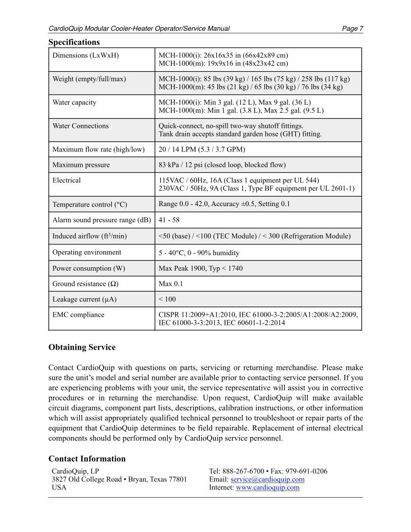
Specifications
Obtaining Service
Contact CardioQuip with questions on parts, servicing or returning merchandise. Please make sure the unit’s model and serial number are available prior to contacting service personnel. If you are experiencing problems with your unit, the service representative will assist you in corrective procedures or in returning the merchandise. Upon request, CardioQuip will make available circuit diagrams, component part lists, descriptions, calibration instructions, or other information which will assist appropriately qualified technical personnel to troubleshoot or repair parts of the equipment that CardioQuip determines to be field repairable. Replacement of internal electrical components should be performed only by CardioQuip service personnel.
Contact Information
Dimensions (LxWxH) MCH-1000(i): 26x16x35 in (66x42x89 cm) MCH-1000(m): 19x9x16 in (48x23x42 cm)
Weight (empty/full/max) MCH-1000(i): 85 lbs (39 kg) / 165 lbs (75 kg) / 258 lbs (117 kg) MCH-1000(m): 45 lbs (21 kg) / 65 lbs (30 kg) / 76 lbs (34 kg)
Water capacity MCH-1000(i): Min 3 gal. (12 L), Max 9 gal. (36 L) MCH-1000(m): Min 1 gal. (3.8 L), Max 2.5 gal. (9.5 L)
Water Connections Quick-connect, no-spill two-way shutoff fittings. Tank drain accepts standard garden hose (GHT) fitting.
Maximum flow rate (high/low) 20 / 14 LPM (5.3 / 3.7 GPM)
Maximum pressure 83 kPa / 12 psi (closed loop, blocked flow)
Electrical 115VAC / 60Hz, 16A (Class 1 equipment per UL 544) 230VAC / 50Hz, 9A (Class 1, Type BF equipment per UL 2601-1)
Temperature control () Range 0.0 - 42.0, Accuracy ±0.5, Setting 0.1
Alarm sound pressure range (dB) 41 - 58
Induced airflow (ft3/min) <50 (base) / <100 (TEC Module) / < 300 (Refrigeration Module)
Operating environment 5 - 40, 0 - 90% humidity
Power consumption (W) Max Peak 1900, Typ < 1740
Ground resistance (Ω) Max 0.1
Leakage current (µA) < 100
EMC compliance CISPR 11:2009+A1:2010, IEC 61000-3-2:2005/A1:2008/A2:2009, IEC 61000-3-3:2013, IEC 60601-1-2:2014
CardioQuip, LP 3827 Old College Road • Bryan, Texas 77801 USA
Tel: 888-267-6700 • Fax: 979-691-0206 Email: [email protected] Internet: www.cardioquip.com
Page CardioQuip Modular Cooler-Heater Operator/Service Manual8
Limited Warranty
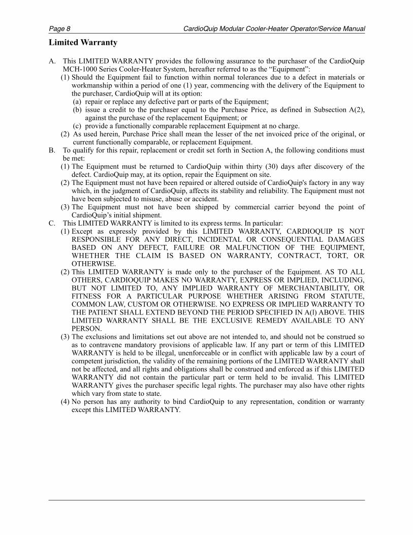
A. This LIMITED WARRANTY provides the following assurance to the purchaser of the CardioQuip MCH-1000 Series Cooler-Heater System, hereafter referred to as the “Equipment”:
(1) Should the Equipment fail to function within normal tolerances due to a defect in materials or workmanship within a period of one (1) year, commencing with the delivery of the Equipment to the purchaser, CardioQuip will at its option: (a) repair or replace any defective part or parts of the Equipment; (b) issue a credit to the purchaser equal to the Purchase Price, as defined in Subsection A(2),
against the purchase of the replacement Equipment; or (c) provide a functionally comparable replacement Equipment at no charge.
(2) As used herein, Purchase Price shall mean the lesser of the net invoiced price of the original, or current functionally comparable, or replacement Equipment.
B. To qualify for this repair, replacement or credit set forth in Section A, the following conditions must be met:
(1) The Equipment must be returned to CardioQuip within thirty (30) days after discovery of the defect. CardioQuip may, at its option, repair the Equipment on site.
(2) The Equipment must not have been repaired or altered outside of CardioQuip's factory in any way which, in the judgment of CardioQuip, affects its stability and reliability. The Equipment must not have been subjected to misuse, abuse or accident.
(3) The Equipment must not have been shipped by commercial carrier beyond the point of CardioQuip’s initial shipment.
C. This LIMITED WARRANTY is limited to its express terms. In particular: (1) Except as expressly provided by this LIMITED WARRANTY, CARDIOQUIP IS NOT
RESPONSIBLE FOR ANY DIRECT, INCIDENTAL OR CONSEQUENTIAL DAMAGES BASED ON ANY DEFECT, FAILURE OR MALFUNCTION OF THE EQUIPMENT, WHETHER THE CLAIM IS BASED ON WARRANTY, CONTRACT, TORT, OR OTHERWISE.
(2) This LIMITED WARRANTY is made only to the purchaser of the Equipment. AS TO ALL OTHERS, CARDIOQUIP MAKES NO WARRANTY, EXPRESS OR IMPLIED, INCLUDING, BUT NOT LIMITED TO, ANY IMPLIED WARRANTY OF MERCHANTABILITY, OR FITNESS FOR A PARTICULAR PURPOSE WHETHER ARISING FROM STATUTE, COMMON LAW, CUSTOM OR OTHERWISE. NO EXPRESS OR IMPLIED WARRANTY TO THE PATIENT SHALL EXTEND BEYOND THE PERIOD SPECIFIED IN A(l) ABOVE. THIS LIMITED WARRANTY SHALL BE THE EXCLUSIVE REMEDY AVAILABLE TO ANY PERSON.
(3) The exclusions and limitations set out above are not intended to, and should not be construed so as to contravene mandatory provisions of applicable law. If any part or term of this LIMITED WARRANTY is held to be illegal, unenforceable or in conflict with applicable law by a court of competent jurisdiction, the validity of the remaining portions of the LIMITED WARRANTY shall not be affected, and all rights and obligations shall be construed and enforced as if this LIMITED WARRANTY did not contain the particular part or term held to be invalid. This LIMITED WARRANTY gives the purchaser specific legal rights. The purchaser may also have other rights which vary from state to state.
(4) No person has any authority to bind CardioQuip to any representation, condition or warranty except this LIMITED WARRANTY.
CardioQuip Modular Cooler-Heater Operator/Service Manual Page 9
Storage
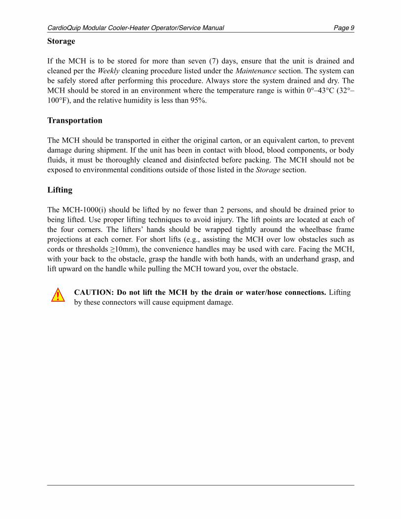
If the MCH is to be stored for more than seven (7) days, ensure that the unit is drained and cleaned per the Weekly cleaning procedure listed under the Maintenance section. The system can be safely stored after performing this procedure. Always store the system drained and dry. The MCH should be stored in an environment where the temperature range is within 0°–43°C (32°–100°F), and the relative humidity is less than 95%.
Transportation
The MCH should be transported in either the original carton, or an equivalent carton, to prevent damage during shipment. If the unit has been in contact with blood, blood components, or body fluids, it must be thoroughly cleaned and disinfected before packing. The MCH should not be exposed to environmental conditions outside of those listed in the Storage section.
Lifting
The MCH-1000(i) should be lifted by no fewer than 2 persons, and should be drained prior to being lifted. Use proper lifting techniques to avoid injury. The lift points are located at each of the four corners. The lifters’ hands should be wrapped tightly around the wheelbase frame projections at each corner. For short lifts (e.g., assisting the MCH over low obstacles such as cords or thresholds ≥10mm), the convenience handles may be used with care. Facing the MCH, with your back to the obstacle, grasp the handle with both hands, with an underhand grasp, and lift upward on the handle while pulling the MCH toward you, over the obstacle.
CAUTION: Do not lift the MCH by the drain or water/hose connections. Lifting by these connectors will cause equipment damage.!
Page CardioQuip Modular Cooler-Heater Operator/Service Manual10
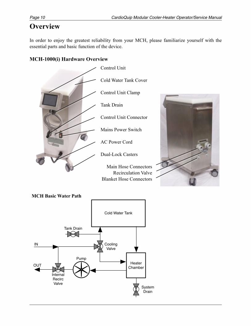
Overview
In order to enjoy the greatest reliability from your MCH, please familiarize yourself with the essential parts and basic function of the device.
MCH-1000(i) Hardware Overview Control Unit
Cold Water Tank Cover
Control Unit Clamp
Tank Drain
Control Unit Connector
Mains Power Switch
AC Power Cord
Dual-Lock Casters
Main Hose Connectors Recirculation Valve
Blanket Hose Connectors !
!
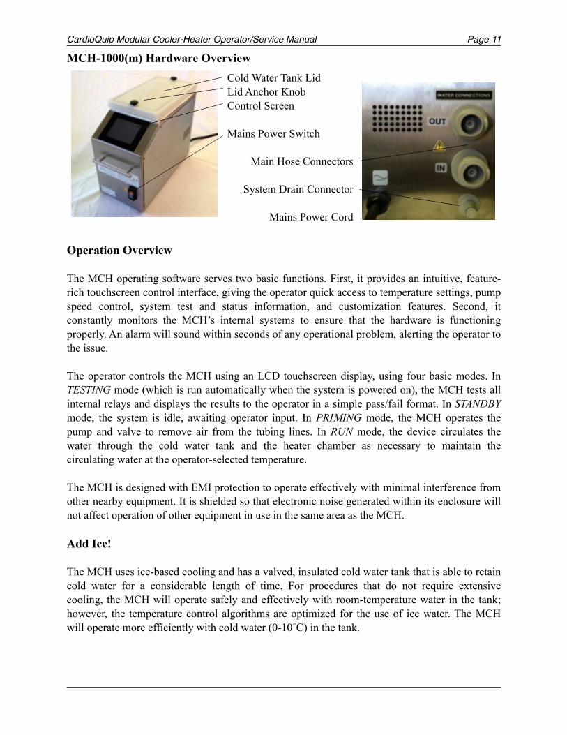
MCH Basic Water Path
!
Cold Water Tank
Heater Chamber
Pump
IN
OUT
InternalRecircValve
CoolingValve
Tank Drain
SystemDrain
CardioQuip Modular Cooler-Heater Operator/Service Manual Page 11
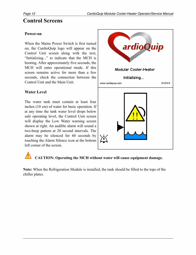
MCH-1000(m) Hardware Overview
Operation Overview
The MCH operating software serves two basic functions. First, it provides an intuitive, feature-rich touchscreen control interface, giving the operator quick access to temperature settings, pump speed control, system test and status information, and customization features. Second, it constantly monitors the MCH’s internal systems to ensure that the hardware is functioning properly. An alarm will sound within seconds of any operational problem, alerting the operator to the issue.
The operator controls the MCH using an LCD touchscreen display, using four basic modes. In TESTING mode (which is run automatically when the system is powered on), the MCH tests all internal relays and displays the results to the operator in a simple pass/fail format. In STANDBY mode, the system is idle, awaiting operator input. In PRIMING mode, the MCH operates the pump and valve to remove air from the tubing lines. In RUN mode, the device circulates the water through the cold water tank and the heater chamber as necessary to maintain the circulating water at the operator-selected temperature.
The MCH is designed with EMI protection to operate effectively with minimal interference from other nearby equipment. It is shielded so that electronic noise generated within its enclosure will not affect operation of other equipment in use in the same area as the MCH.
Add Ice!
The MCH uses ice-based cooling and has a valved, insulated cold water tank that is able to retain cold water for a considerable length of time. For procedures that do not require extensive cooling, the MCH will operate safely and effectively with room-temperature water in the tank; however, the temperature control algorithms are optimized for the use of ice water. The MCH will operate more efficiently with cold water (0-10˚C) in the tank.
Cold Water Tank Lid Lid Anchor Knob Control Screen
Mains Power Switch
Main Hose Connectors
System Drain Connector
Mains Power Cord! !
Page CardioQuip Modular Cooler-Heater Operator/Service Manual12
Control Screens
Note: When the Refrigeration Module is installed, the tank should be filled to the tops of the chiller plates.
Power-on
When the Mains Power Switch is first turned on, the CardioQuip logo will appear on the Control Unit screen along with the text, “Initializing...” to indicate that the MCH is booting. After approximately five seconds, the MCH will enter operational mode. If this screen remains active for more than a few seconds, check the connection between the Control Unit and the Main Unit.
Water Level
The water tank must contain at least four inches (10 cm) of water for basic operation. If at any time the tank water level drops below safe operating level, the Control Unit screen will display the Low Water warning screen shown at right. An audible alarm will sound a two-beep pattern at 20 second intervals. The alarm may be silenced for 60 seconds by touching the Alarm Silence icon at the bottom left corner of the screen.
!
!
CAUTION: Operating the MCH without water will cause equipment damage.!
CardioQuip Modular Cooler-Heater Operator/Service Manual Page 13
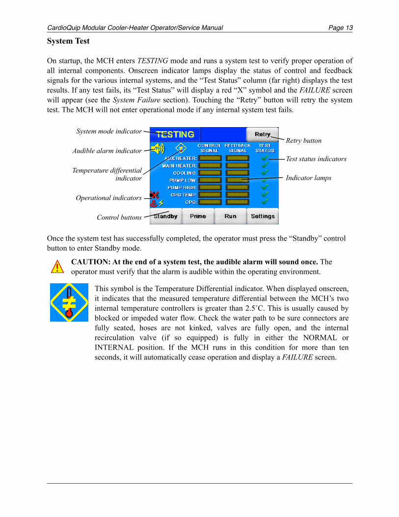
System Test
On startup, the MCH enters TESTING mode and runs a system test to verify proper operation of all internal components. Onscreen indicator lamps display the status of control and feedback signals for the various internal systems, and the “Test Status” column (far right) displays the test results. If any test fails, its “Test Status” will display a red “X” symbol and the FAILURE screen will appear (see the System Failure section). Touching the “Retry” button will retry the system test. The MCH will not enter operational mode if any internal system test fails.
Once the system test has successfully completed, the operator must press the “Standby” control button to enter Standby mode.
CAUTION: At the end of a system test, the audible alarm will sound once. The operator must verify that the alarm is audible within the operating environment.!
This symbol is the Temperature Differential indicator. When displayed onscreen, it indicates that the measured temperature differential between the MCH’s two internal temperature controllers is greater than 2.5˚C. This is usually caused by blocked or impeded water flow. Check the water path to be sure connectors are fully seated, hoses are not kinked, valves are fully open, and the internal recirculation valve (if so equipped) is fully in either the NORMAL or INTERNAL position. If the MCH runs in this condition for more than ten seconds, it will automatically cease operation and display a FAILURE screen.
!
Retry button
Test status indicators
Indicator lamps
System mode indicator
Audible alarm indicator
Temperature differential indicator
Operational indicators
Control buttons
Page CardioQuip Modular Cooler-Heater Operator/Service Manual14
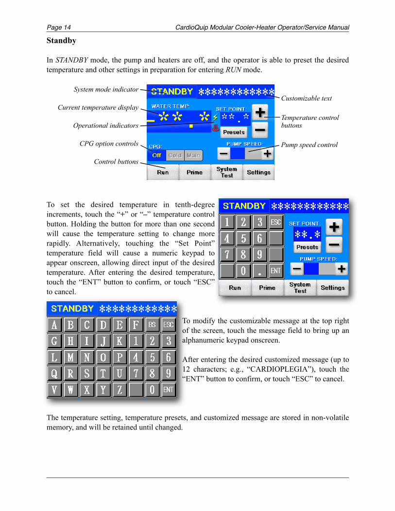
Standby
In STANDBY mode, the pump and heaters are off, and the operator is able to preset the desired temperature and other settings in preparation for entering RUN mode.
To set the desired temperature in tenth-degree increments, touch the “+” or “–” temperature control button. Holding the button for more than one second will cause the temperature setting to change more rapidly. Alternatively, touching the “Set Point” temperature field will cause a numeric keypad to appear onscreen, allowing direct input of the desired temperature. After entering the desired temperature, touch the “ENT” button to confirm, or touch “ESC” to cancel.
To modify the customizable message at the top right of the screen, touch the message field to bring up an alphanumeric keypad onscreen.
After entering the desired customized message (up to 12 characters; e.g., “CARDIOPLEGIA”), touch the “ENT” button to confirm, or touch “ESC” to cancel.
The temperature setting, temperature presets, and customized message are stored in non-volatile memory, and will be retained until changed.
Customizable text
Temperature control buttons
Pump speed control
System mode indicator
Current temperature display
Operational indicators
CPG option controls
Control buttons
CardioQuip Modular Cooler-Heater Operator/Service Manual Page 15
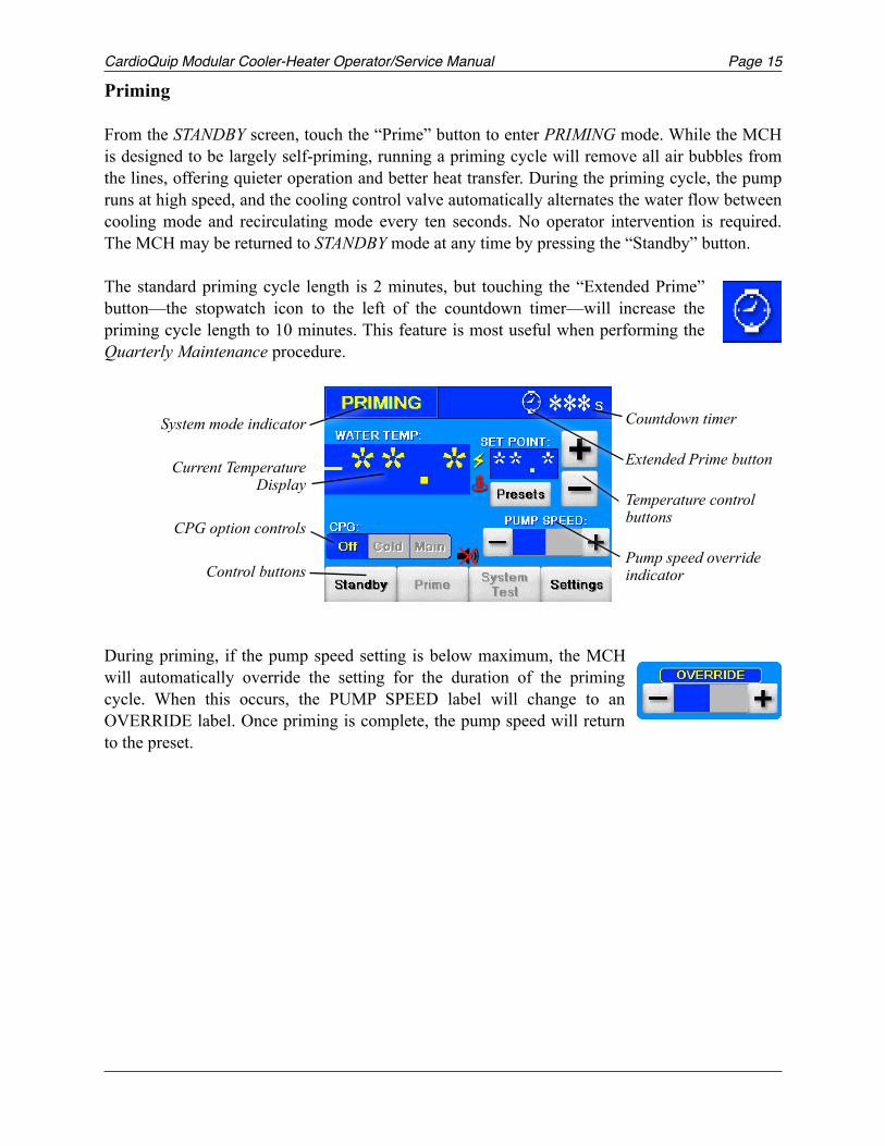
Priming
From the STANDBY screen, touch the “Prime” button to enter PRIMING mode. While the MCH is designed to be largely self-priming, running a priming cycle will remove all air bubbles from the lines, offering quieter operation and better heat transfer. During the priming cycle, the pump runs at high speed, and the cooling control valve automatically alternates the water flow between cooling mode and recirculating mode every ten seconds. No operator intervention is required. The MCH may be returned to STANDBY mode at any time by pressing the “Standby” button.
The standard priming cycle length is 2 minutes, but touching the “Extended Prime” button—the stopwatch icon to the left of the countdown timer—will increase the priming cycle length to 10 minutes. This feature is most useful when performing the Quarterly Maintenance procedure.
During priming, if the pump speed setting is below maximum, the MCH will automatically override the setting for the duration of the priming cycle. When this occurs, the PUMP SPEED label will change to an OVERRIDE label. Once priming is complete, the pump speed will return to the preset.
Countdown timer
Extended Prime button
Temperature control buttons
Pump speed override indicator
System mode indicator
Current Temperature Display
CPG option controls
Control buttons
Page CardioQuip Modular Cooler-Heater Operator/Service Manual16
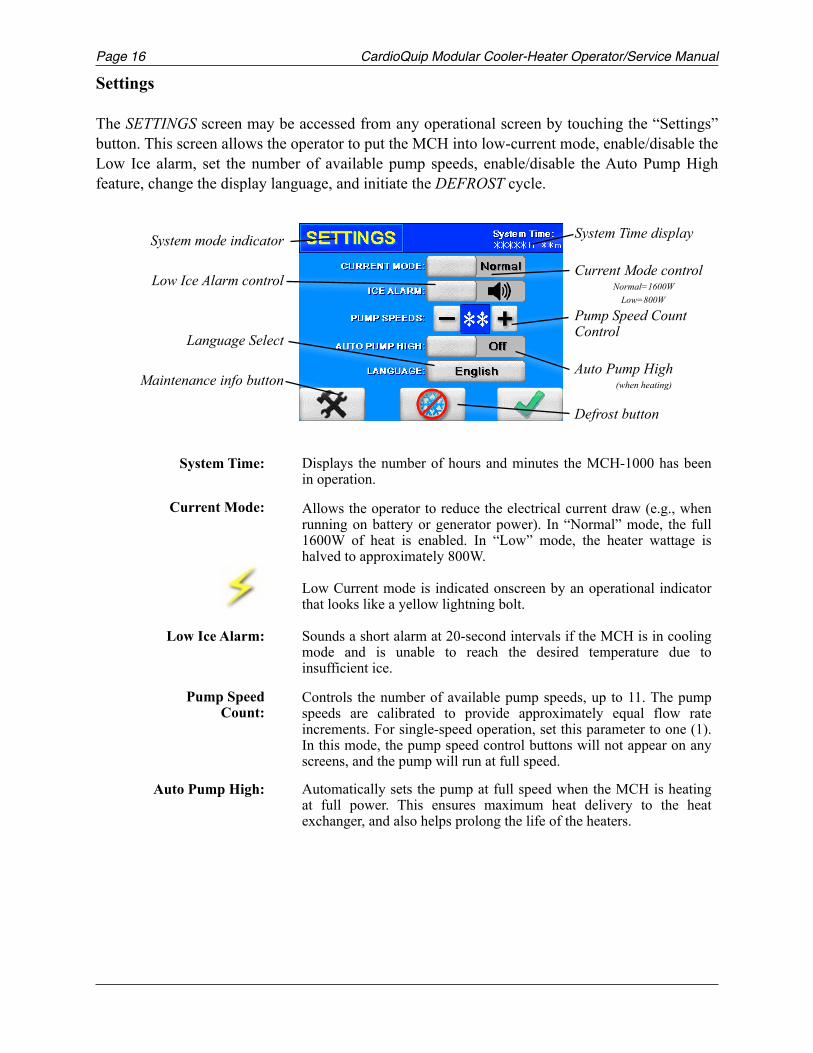
Settings
The SETTINGS screen may be accessed from any operational screen by touching the “Settings” button. This screen allows the operator to put the MCH into low-current mode, enable/disable the Low Ice alarm, set the number of available pump speeds, enable/disable the Auto Pump High feature, change the display language, and initiate the DEFROST cycle.
System Time: Displays the number of hours and minutes the MCH-1000 has been in operation.
Allows the operator to reduce the electrical current draw (e.g., when running on battery or generator power). In “Normal” mode, the full 1600W of heat is enabled. In “Low” mode, the heater wattage is halved to approximately 800W.
Low Current mode is indicated onscreen by an operational indicator that looks like a yellow lightning bolt.
Low Ice Alarm: Sounds a short alarm at 20-second intervals if the MCH is in cooling mode and is unable to reach the desired temperature due to insufficient ice.
Pump Speed Count:
Controls the number of available pump speeds, up to 11. The pump speeds are calibrated to provide approximately equal flow rate increments. For single-speed operation, set this parameter to one (1). In this mode, the pump speed control buttons will not appear on any screens, and the pump will run at full speed.
Auto Pump High: Automatically sets the pump at full speed when the MCH is heating at full power. This ensures maximum heat delivery to the heat exchanger, and also helps prolong the life of the heaters.
Current Mode:
!
System Time display
Current Mode control Normal=1600W
Low=800W
Pump Speed Count Control
Auto Pump High (when heating)
Defrost button
System mode indicator
Low Ice Alarm control
Language Select
Maintenance info button
CardioQuip Modular Cooler-Heater Operator/Service Manual Page 17
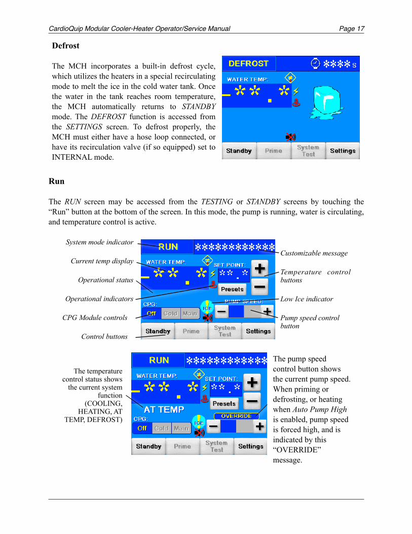
Run
The RUN screen may be accessed from the TESTING or STANDBY screens by touching the “Run” button at the bottom of the screen. In this mode, the pump is running, water is circulating, and temperature control is active.
Defrost
The MCH incorporates a built-in defrost cycle, which utilizes the heaters in a special recirculating mode to melt the ice in the cold water tank. Once the water in the tank reaches room temperature, the MCH automatically returns to STANDBY mode. The DEFROST function is accessed from the SETTINGS screen. To defrost properly, the MCH must either have a hose loop connected, or have its recirculation valve (if so equipped) set to INTERNAL mode. !
Customizable message
Temperature control buttons
Low Ice indicator
Pump speed control button
System mode indicator
Current temp display
Operational status
Operational indicators
CPG Module controls
Control buttons
The pump speed control button shows the current pump speed. When priming or defrosting, or heating when Auto Pump High is enabled, pump speed is forced high, and is indicated by this “OVERRIDE” message.
The temperature control status shows
the current system function
(COOLING, HEATING, AT
TEMP, DEFROST)
Page CardioQuip Modular Cooler-Heater Operator/Service Manual18
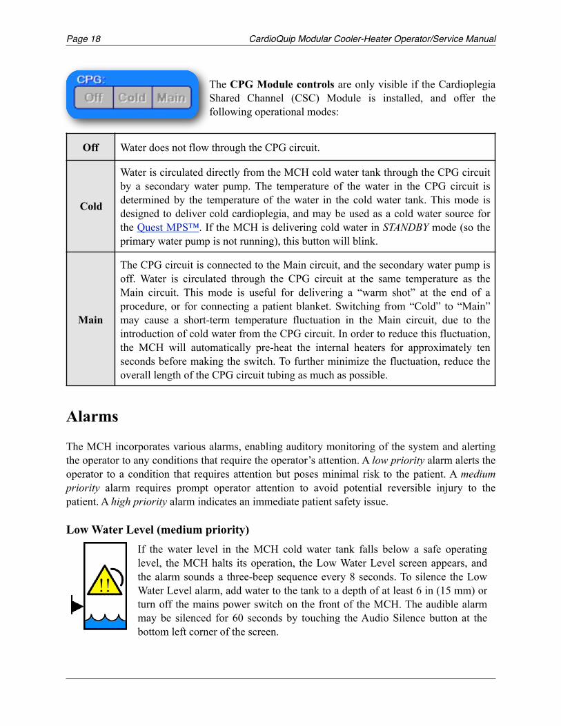
The CPG Module controls are only visible if the Cardioplegia Shared Channel (CSC) Module is installed, and offer the following operational modes:
Alarms
The MCH incorporates various alarms, enabling auditory monitoring of the system and alerting the operator to any conditions that require the operator’s attention. A low priority alarm alerts the operator to a condition that requires attention but poses minimal risk to the patient. A medium priority alarm requires prompt operator attention to avoid potential reversible injury to the patient. A high priority alarm indicates an immediate patient safety issue.
Low Water Level (medium priority)
Off Water does not flow through the CPG circuit.
Cold
Water is circulated directly from the MCH cold water tank through the CPG circuit by a secondary water pump. The temperature of the water in the CPG circuit is determined by the temperature of the water in the cold water tank. This mode is designed to deliver cold cardioplegia, and may be used as a cold water source for the Quest MPS™. If the MCH is delivering cold water in STANDBY mode (so the primary water pump is not running), this button will blink.
Main
The CPG circuit is connected to the Main circuit, and the secondary water pump is off. Water is circulated through the CPG circuit at the same temperature as the Main circuit. This mode is useful for delivering a “warm shot” at the end of a procedure, or for connecting a patient blanket. Switching from “Cold” to “Main” may cause a short-term temperature fluctuation in the Main circuit, due to the introduction of cold water from the CPG circuit. In order to reduce this fluctuation, the MCH will automatically pre-heat the internal heaters for approximately ten seconds before making the switch. To further minimize the fluctuation, reduce the overall length of the CPG circuit tubing as much as possible.
If the water level in the MCH cold water tank falls below a safe operating level, the MCH halts its operation, the Low Water Level screen appears, and the alarm sounds a three-beep sequence every 8 seconds. To silence the Low Water Level alarm, add water to the tank to a depth of at least 6 in (15 mm) or turn off the mains power switch on the front of the MCH. The audible alarm may be silenced for 60 seconds by touching the Audio Silence button at the bottom left corner of the screen.!
CardioQuip Modular Cooler-Heater Operator/Service Manual Page 19
Low Ice (low priority)
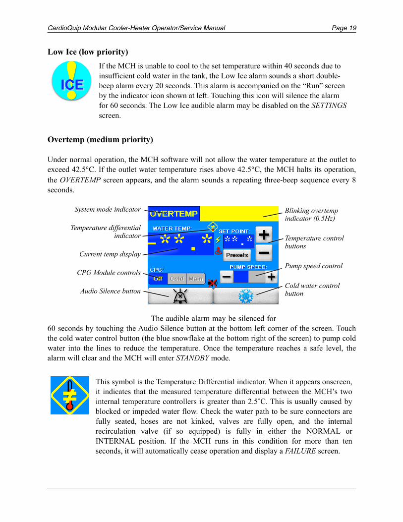
Overtemp (medium priority)
Under normal operation, the MCH software will not allow the water temperature at the outlet to exceed 42.5. If the outlet water temperature rises above 42.5, the MCH halts its operation, the OVERTEMP screen appears, and the alarm sounds a repeating three-beep sequence every 8 seconds.
The audible alarm may be silenced for 60 seconds by touching the Audio Silence button at the bottom left corner of the screen. Touch the cold water control button (the blue snowflake at the bottom right of the screen) to pump cold water into the lines to reduce the temperature. Once the temperature reaches a safe level, the alarm will clear and the MCH will enter STANDBY mode.
If the MCH is unable to cool to the set temperature within 40 seconds due to insufficient cold water in the tank, the Low Ice alarm sounds a short double-beep alarm every 20 seconds. This alarm is accompanied on the “Run” screen by the indicator icon shown at left. Touching this icon will silence the alarm for 60 seconds. The Low Ice audible alarm may be disabled on the SETTINGS screen.
!
This symbol is the Temperature Differential indicator. When it appears onscreen, it indicates that the measured temperature differential between the MCH’s two internal temperature controllers is greater than 2.5˚C. This is usually caused by blocked or impeded water flow. Check the water path to be sure connectors are fully seated, hoses are not kinked, valves are fully open, and the internal recirculation valve (if so equipped) is fully in either the NORMAL or INTERNAL position. If the MCH runs in this condition for more than ten seconds, it will automatically cease operation and display a FAILURE screen.
!
Blinking overtemp indicator (0.5Hz)
Temperature control buttons
Pump speed control
Cold water control button
System mode indicator
Temperature differential indicator
Current temp display
CPG Module controls
Audio Silence button
Page CardioQuip Modular Cooler-Heater Operator/Service Manual20
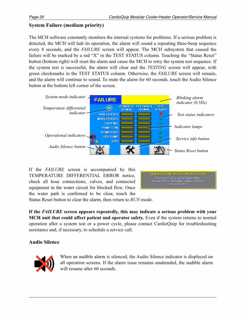
System Failure (medium priority)
The MCH software constantly monitors the internal systems for problems. If a serious problem is detected, the MCH will halt its operation, the alarm will sound a repeating three-beep sequence every 8 seconds, and the FAILURE screen will appear. The MCH subsystem that caused the failure will be marked by a red “X” in the TEST STATUS column. Touching the “Status Reset” button (bottom right) will reset the alarm and cause the MCH to retry the system test sequence. If the system test is successful, the alarm will clear and the TESTING screen will appear, with green checkmarks in the TEST STATUS column. Otherwise, the FAILURE screen will remain, and the alarm will continue to sound. To mute the alarm for 60 seconds, touch the Audio Silence button at the bottom left corner of the screen.
If the FAILURE screen is accompanied by this TEMPERATURE DIFFERENTIAL ERROR notice, check all hose connections, valves, and connected equipment in the water circuit for blocked flow. Once the water path is confirmed to be clear, touch the Status Reset button to clear the alarm, then return to RUN mode.
If the FAILURE screen appears repeatedly, this may indicate a serious problem with your MCH unit that could affect patient and operator safety. Even if the system returns to normal operation after a system test or a power cycle, please contact CardioQuip for troubleshooting assistance and, if necessary, to schedule a service call.
Audio Silence
When an audible alarm is silenced, the Audio Silence indicator is displayed on all operation screens. If the alarm issue remains unattended, the audible alarm will resume after 60 seconds.
!
Blinking alarm indicator (0.5Hz)
Test status indicators
Indicator lamps
Service info button
Status Reset button
System mode indicator
Temperature differential indicator
Operational indicators
Audio Silence button
CardioQuip Modular Cooler-Heater Operator/Service Manual Page 21
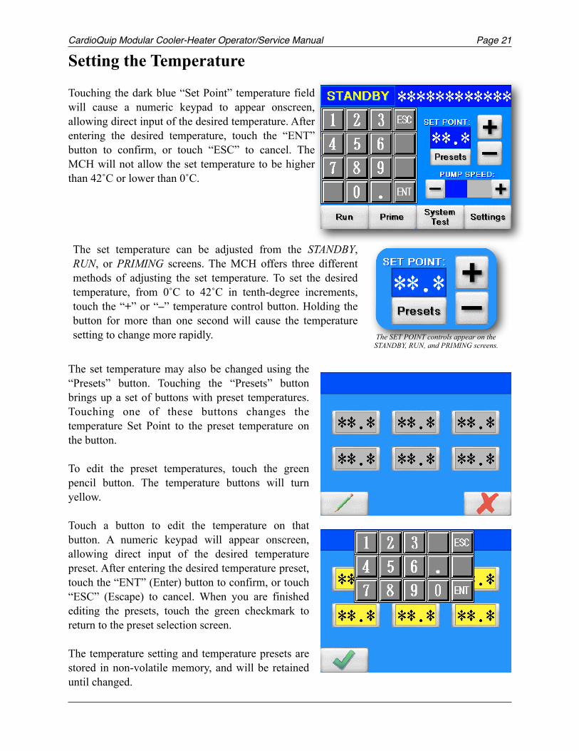
Setting the Temperature
Touching the dark blue “Set Point” temperature field will cause a numeric keypad to appear onscreen, allowing direct input of the desired temperature. After entering the desired temperature, touch the “ENT” button to confirm, or touch “ESC” to cancel. The MCH will not allow the set temperature to be higher than 42˚C or lower than 0˚C.
The set temperature may also be changed using the “Presets” button. Touching the “Presets” button brings up a set of buttons with preset temperatures. Touching one of these buttons changes the temperature Set Point to the preset temperature on the button.
To edit the preset temperatures, touch the green pencil button. The temperature buttons will turn yellow.
Touch a button to edit the temperature on that button. A numeric keypad will appear onscreen, allowing direct input of the desired temperature preset. After entering the desired temperature preset, touch the “ENT” (Enter) button to confirm, or touch “ESC” (Escape) to cancel. When you are finished editing the presets, touch the green checkmark to return to the preset selection screen.
The temperature setting and temperature presets are stored in non-volatile memory, and will be retained until changed.
The set temperature can be adjusted from the STANDBY, RUN, or PRIMING screens. The MCH offers three different methods of adjusting the set temperature. To set the desired temperature, from 0˚C to 42˚C in tenth-degree increments, touch the “+” or “–” temperature control button. Holding the button for more than one second will cause the temperature setting to change more rapidly.
! The SET POINT controls appear on the STANDBY, RUN, and PRIMING screens.
Page CardioQuip Modular Cooler-Heater Operator/Service Manual22
Connectors, Valves, & Hoses
The MCH series utilizes various non-spill connectors and valves to provide a convenient, drip-free water path. Note that the brass Hansen-style connectors at the remote (oxygenator) end of the standard hose kit are not valved, and will leak when disconnected.
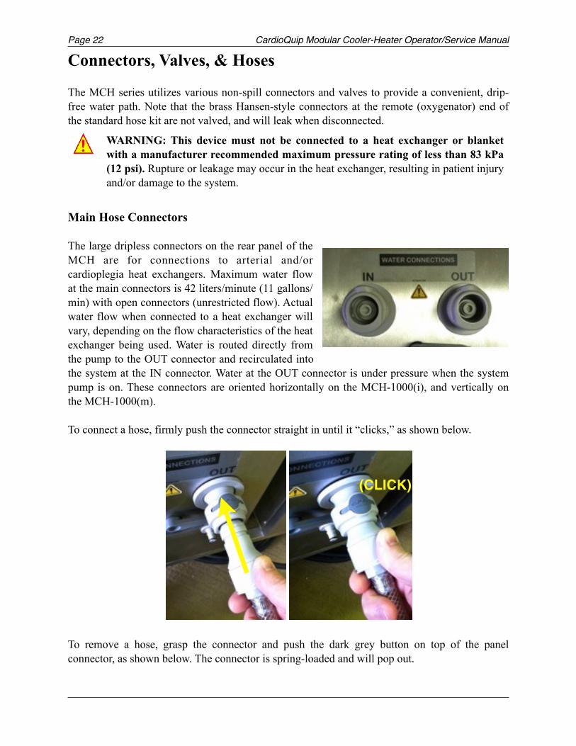
Main Hose Connectors
The large dripless connectors on the rear panel of the MCH are for connections to arterial and/or cardioplegia heat exchangers. Maximum water flow at the main connectors is 42 liters/minute (11 gallons/min) with open connectors (unrestricted flow). Actual water flow when connected to a heat exchanger will vary, depending on the flow characteristics of the heat exchanger being used. Water is routed directly from the pump to the OUT connector and recirculated into the system at the IN connector. Water at the OUT connector is under pressure when the system pump is on. These connectors are oriented horizontally on the MCH-1000(i), and vertically on the MCH-1000(m).
To connect a hose, firmly push the connector straight in until it “clicks,” as shown below.
! !
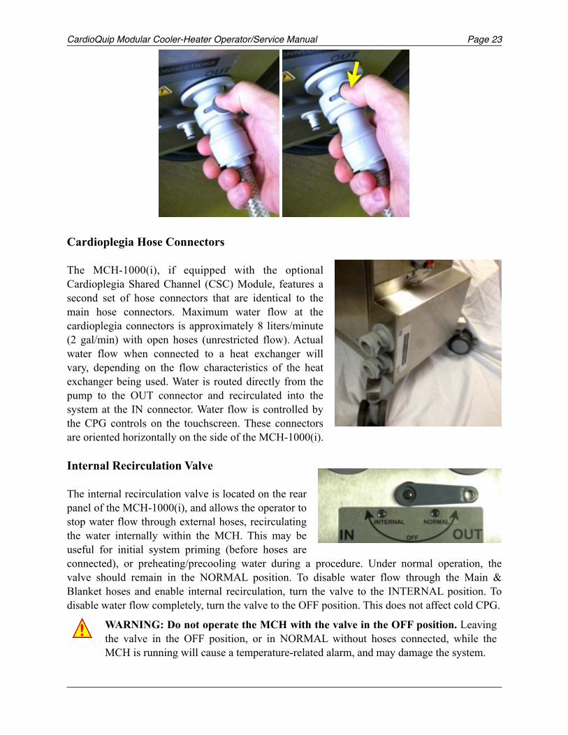
To remove a hose, grasp the connector and push the dark grey button on top of the panel connector, as shown below. The connector is spring-loaded and will pop out.
WARNING: This device must not be connected to a heat exchanger or blanket with a manufacturer recommended maximum pressure rating of less than 83 kPa (12 psi). Rupture or leakage may occur in the heat exchanger, resulting in patient injury and/or damage to the system.
!
(CLICK)
CardioQuip Modular Cooler-Heater Operator/Service Manual Page 23
! !
Cardioplegia Hose Connectors The MCH-1000(i), if equipped with the optional Cardioplegia Shared Channel (CSC) Module, features a second set of hose connectors that are identical to the main hose connectors. Maximum water flow at the cardioplegia connectors is approximately 8 liters/minute (2 gal/min) with open hoses (unrestricted flow). Actual water flow when connected to a heat exchanger will vary, depending on the flow characteristics of the heat exchanger being used. Water is routed directly from the pump to the OUT connector and recirculated into the system at the IN connector. Water flow is controlled by the CPG controls on the touchscreen. These connectors are oriented horizontally on the side of the MCH-1000(i).
Internal Recirculation Valve
The internal recirculation valve is located on the rear panel of the MCH-1000(i), and allows the operator to stop water flow through external hoses, recirculating the water internally within the MCH. This may be useful for initial system priming (before hoses are connected), or preheating/precooling water during a procedure. Under normal operation, the valve should remain in the NORMAL position. To disable water flow through the Main & Blanket hoses and enable internal recirculation, turn the valve to the INTERNAL position. To disable water flow completely, turn the valve to the OFF position. This does not affect cold CPG.
WARNING: Do not operate the MCH with the valve in the OFF position. Leaving the valve in the OFF position, or in NORMAL without hoses connected, while the MCH is running will cause a temperature-related alarm, and may damage the system.
!
Page CardioQuip Modular Cooler-Heater Operator/Service Manual24
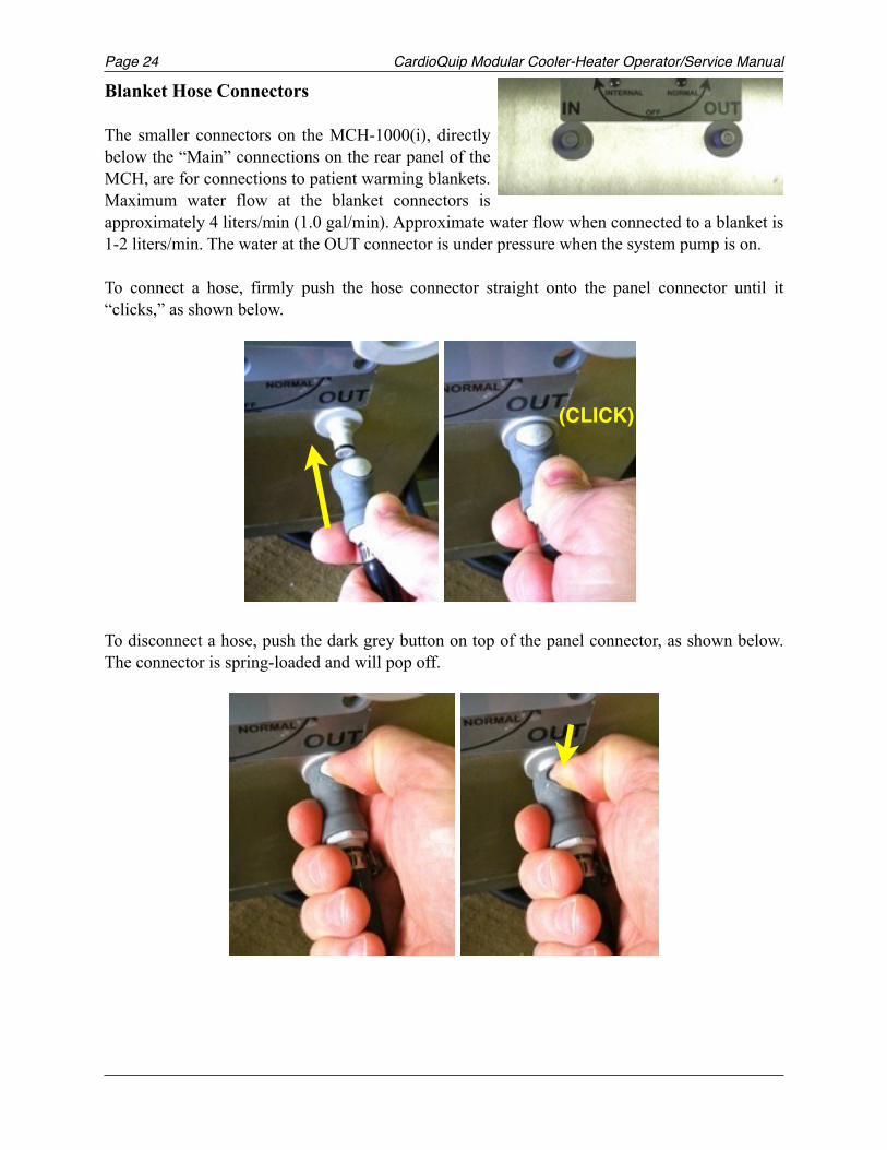
Blanket Hose Connectors
The smaller connectors on the MCH-1000(i), directly below the “Main” connections on the rear panel of the MCH, are for connections to patient warming blankets. Maximum water flow at the blanket connectors is approximately 4 liters/min (1.0 gal/min). Approximate water flow when connected to a blanket is 1-2 liters/min. The water at the OUT connector is under pressure when the system pump is on.
To connect a hose, firmly push the hose connector straight onto the panel connector until it “clicks,” as shown below.
! !
To disconnect a hose, push the dark grey button on top of the panel connector, as shown below. The connector is spring-loaded and will pop off.
! !
(CLICK)
CardioQuip Modular Cooler-Heater Operator/Service Manual Page 25
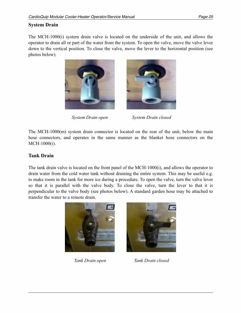
System Drain
The MCH-1000(i) system drain valve is located on the underside of the unit, and allows the operator to drain all or part of the water from the system. To open the valve, move the valve lever down to the vertical position. To close the valve, move the lever to the horizontal position (see photos below).
The MCH-1000(m) system drain connector is located on the rear of the unit, below the main hose connectors, and operates in the same manner as the blanket hose connectors on the MCH-1000(i).
Tank Drain
The tank drain valve is located on the front panel of the MCH-1000(i), and allows the operator to drain water from the cold water tank without draining the entire system. This may be useful e.g. to make room in the tank for more ice during a procedure. To open the valve, turn the valve lever so that it is parallel with the valve body. To close the valve, turn the lever to that it is perpendicular to the valve body (see photos below). A standard garden hose may be attached to transfer the water to a remote drain.
System Drain open System Drain closed
! !
Tank Drain open Tank Drain closed
! !
Page CardioQuip Modular Cooler-Heater Operator/Service Manual26
Hose Kits
The MCH Series supports multiple hose kit configurations, to suit the growing array of perfusion applications. With any hose kit, quarterly maintenance must include checking the connectors for leaks, and tightening the clamps if needed. The plastic tubing must also be inspected at least quarterly, and replaced when it becomes clouded, or when the plastic loses its flexibility. Antimicrobial tubing should be replaced every two years, as its antimicrobial properties diminish with long-term use.
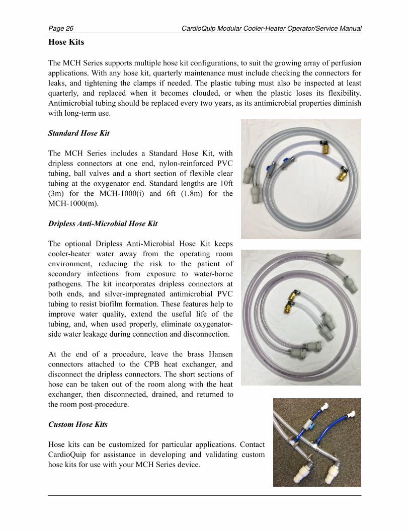
Standard Hose Kit
The MCH Series includes a Standard Hose Kit, with dripless connectors at one end, nylon-reinforced PVC tubing, ball valves and a short section of flexible clear tubing at the oxygenator end. Standard lengths are 10ft (3m) for the MCH-1000(i) and 6ft (1.8m) for the MCH-1000(m).
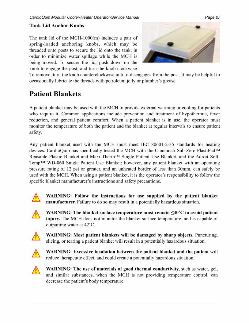
Dripless Anti-Microbial Hose Kit The optional Dripless Anti-Microbial Hose Kit keeps cooler-heater water away from the operating room environment, reducing the risk to the patient of secondary infections from exposure to water-borne pathogens. The kit incorporates dripless connectors at both ends, and silver-impregnated antimicrobial PVC tubing to resist biofilm formation. These features help to improve water quality, extend the useful life of the tubing, and, when used properly, eliminate oxygenator-side water leakage during connection and disconnection.
At the end of a procedure, leave the brass Hansen connectors attached to the CPB heat exchanger, and disconnect the dripless connectors. The short sections of hose can be taken out of the room along with the heat exchanger, then disconnected, drained, and returned to the room post-procedure.
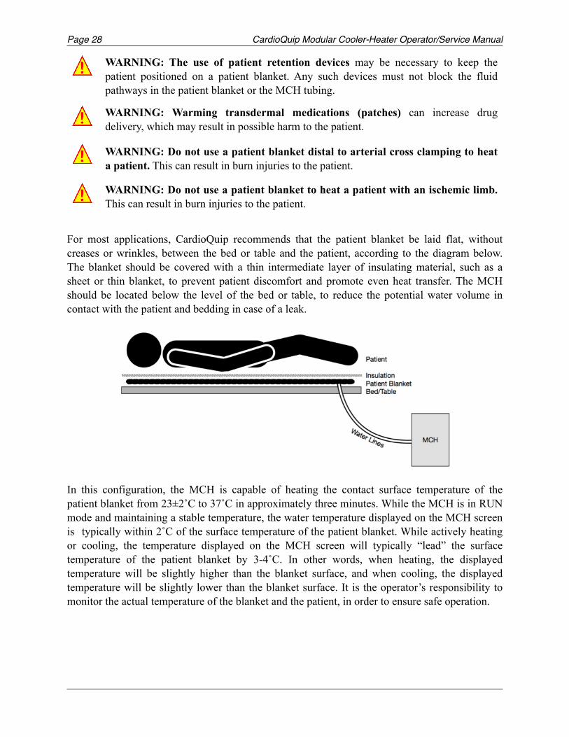
Custom Hose Kits
Hose kits can be customized for particular applications. Contact CardioQuip for assistance in developing and validating custom hose kits for use with your MCH Series device.
CardioQuip Modular Cooler-Heater Operator/Service Manual Page 27
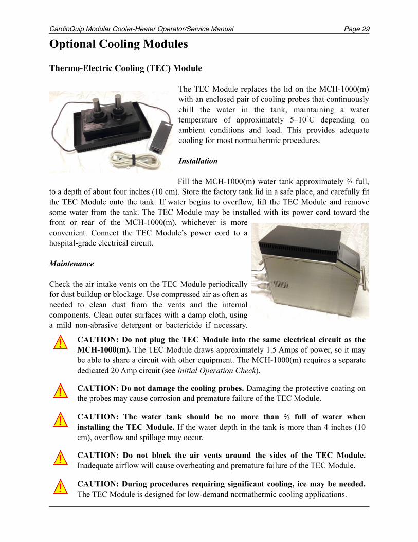
Tank Lid Anchor Knobs
The tank lid of the MCH-1000(m) includes a pair of spring-loaded anchoring knobs, which may be threaded onto posts to secure the lid onto the tank, in order to minimize water spillage while the MCH is being moved. To secure the lid, push down on the knob to engage the post, and turn the knob clockwise. To remove, turn the knob counterclockwise until it disengages from the post. It may be helpful to occasionally lubricate the threads with petroleum jelly or plumber’s grease.
Patient Blankets
A patient blanket may be used with the MCH to provide external warming or cooling for patients who require it. Common applications include prevention and treatment of hypothermia, fever reduction, and general patient comfort. When a patient blanket is in use, the operator must monitor the temperature of both the patient and the blanket at regular intervals to ensure patient safety.
Any patient blanket used with the MCH must meet IEC 80601-2-35 standards for heating devices. CardioQuip has specifically tested the MCH with the Cincinnati Sub-Zero PlastiPad™ Reusable Plastic Blanket and Maxi-Therm™ Single Patient Use Blanket, and the Adroit Soft-Temp™ WD-060 Single Patient Use Blanket; however, any patient blanket with an operating pressure rating of 12 psi or greater, and an unheated border of less than 30mm, can safely be used with the MCH. When using a patient blanket, it is the operator’s responsibility to follow the specific blanket manufacturer’s instructions and safety precautions.
WARNING: Follow the instructions for use supplied by the patient blanket manufacturer. Failure to do so may result in a potentially hazardous situation.
WARNING: The blanket surface temperature must remain ≤40˚C to avoid patient injury. The MCH does not monitor the blanket surface temperature, and is capable of outputting water at 42˚C.
WARNING: Most patient blankets will be damaged by sharp objects. Puncturing, slicing, or tearing a patient blanket will result in a potentially hazardous situation.
WARNING: Excessive insulation between the patient blanket and the patient will reduce therapeutic effect, and could create a potentially hazardous situation.
WARNING: The use of materials of good thermal conductivity, such as water, gel, and similar substances, when the MCH is not providing temperature control, can decrease the patient’s body temperature.
!
!
!
!
!
Page CardioQuip Modular Cooler-Heater Operator/Service Manual28
For most applications, CardioQuip recommends that the patient blanket be laid flat, without creases or wrinkles, between the bed or table and the patient, according to the diagram below. The blanket should be covered with a thin intermediate layer of insulating material, such as a sheet or thin blanket, to prevent patient discomfort and promote even heat transfer. The MCH should be located below the level of the bed or table, to reduce the potential water volume in contact with the patient and bedding in case of a leak.
In this configuration, the MCH is capable of heating the contact surface temperature of the patient blanket from 23±2˚C to 37˚C in approximately three minutes. While the MCH is in RUN mode and maintaining a stable temperature, the water temperature displayed on the MCH screen is typically within 2˚C of the surface temperature of the patient blanket. While actively heating or cooling, the temperature displayed on the MCH screen will typically “lead” the surface temperature of the patient blanket by 3-4˚C. In other words, when heating, the displayed temperature will be slightly higher than the blanket surface, and when cooling, the displayed temperature will be slightly lower than the blanket surface. It is the operator’s responsibility to monitor the actual temperature of the blanket and the patient, in order to ensure safe operation.
WARNING: The use of patient retention devices may be necessary to keep the patient positioned on a patient blanket. Any such devices must not block the fluid pathways in the patient blanket or the MCH tubing.
WARNING: Warming transdermal medications (patches) can increase drug delivery, which may result in possible harm to the patient.
WARNING: Do not use a patient blanket distal to arterial cross clamping to heat a patient. This can result in burn injuries to the patient.
WARNING: Do not use a patient blanket to heat a patient with an ischemic limb. This can result in burn injuries to the patient.
!
!
!
!
CardioQuip Modular Cooler-Heater Operator/Service Manual Page 29
Optional Cooling Modules
Thermo-Electric Cooling (TEC) Module
The TEC Module replaces the lid on the MCH-1000(m) with an enclosed pair of cooling probes that continuously chill the water in the tank, maintaining a water temperature of approximately 5–10˚C depending on ambient conditions and load. This provides adequate cooling for most normathermic procedures.
Installation
Fill the MCH-1000(m) water tank approximately ⅔ full, to a depth of about four inches (10 cm). Store the factory tank lid in a safe place, and carefully fit the TEC Module onto the tank. If water begins to overflow, lift the TEC Module and remove some water from the tank. The TEC Module may be installed with its power cord toward the front or rear of the MCH-1000(m), whichever is more convenient. Connect the TEC Module’s power cord to a hospital-grade electrical circuit.
Maintenance
Check the air intake vents on the TEC Module periodically for dust buildup or blockage. Use compressed air as often as needed to clean dust from the vents and the internal components. Clean outer surfaces with a damp cloth, using a mild non-abrasive detergent or bactericide if necessary.
CAUTION: Do not plug the TEC Module into the same electrical circuit as the MCH-1000(m). The TEC Module draws approximately 1.5 Amps of power, so it may be able to share a circuit with other equipment. The MCH-1000(m) requires a separate dedicated 20 Amp circuit (see Initial Operation Check).
!
CAUTION: Do not damage the cooling probes. Damaging the protective coating on the probes may cause corrosion and premature failure of the TEC Module.!
CAUTION: The water tank should be no more than ⅔ full of water when installing the TEC Module. If the water depth in the tank is more than 4 inches (10 cm), overflow and spillage may occur.
!
CAUTION: Do not block the air vents around the sides of the TEC Module. Inadequate airflow will cause overheating and premature failure of the TEC Module.!
CAUTION: During procedures requiring significant cooling, ice may be needed. The TEC Module is designed for low-demand normathermic cooling applications.!
Page CardioQuip Modular Cooler-Heater Operator/Service Manual30
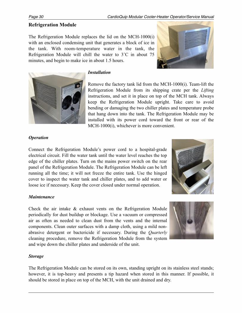
Refrigeration Module
The Refrigeration Module replaces the lid on the MCH-1000(i) with an enclosed condensing unit that generates a block of ice in the tank. With room-temperature water in the tank, the Refrigeration Module will chill the water to 3˚C in about 75 minutes, and begin to make ice in about 1.5 hours.
Installation
Remove the factory tank lid from the MCH-1000(i). Team-lift the Refrigeration Module from its shipping crate per the Lifting instructions, and set it in place on top of the MCH tank. Always keep the Refrigeration Module upright. Take care to avoid bending or damaging the two chiller plates and temperature probe that hang down into the tank. The Refrigeration Module may be installed with its power cord toward the front or rear of the MCH-1000(i), whichever is more convenient.
Operation
Connect the Refrigeration Module’s power cord to a hospital-grade electrical circuit. Fill the water tank until the water level reaches the top edge of the chiller plates. Turn on the mains power switch on the rear panel of the Refrigeration Module. The Refrigeration Module can be left running all the time; it will not freeze the entire tank. Use the hinged cover to inspect the water tank and chiller plates, and to add water or loose ice if necessary. Keep the cover closed under normal operation. Maintenance
Check the air intake & exhaust vents on the Refrigeration Module periodically for dust buildup or blockage. Use a vacuum or compressed air as often as needed to clean dust from the vents and the internal components. Clean outer surfaces with a damp cloth, using a mild non-abrasive detergent or bactericide if necessary. During the Quarterly cleaning procedure, remove the Refrigeration Module from the system and wipe down the chiller plates and underside of the unit.
Storage
The Refrigeration Module can be stored on its own, standing upright on its stainless steel stands; however, it is top-heavy and presents a tip hazard when stored in this manner. If possible, it should be stored in place on top of the MCH, with the unit drained and dry.
CardioQuip Modular Cooler-Heater Operator/Service Manual Page 31
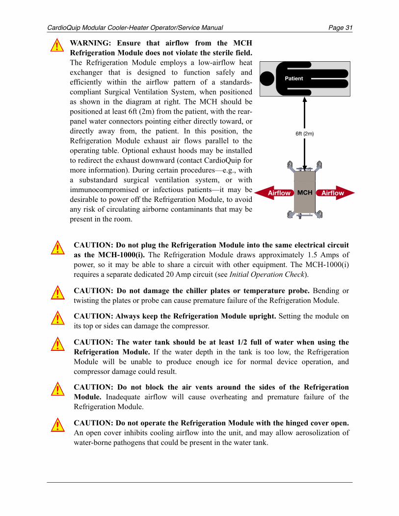
WARNING: Ensure that airflow from the MCH Refrigeration Module does not violate the sterile field. The Refrigeration Module employs a low-airflow heat exchanger that is designed to function safely and efficiently within the airflow pattern of a standards-compliant Surgical Ventilation System, when positioned as shown in the diagram at right. The MCH should be positioned at least 6ft (2m) from the patient, with the rear-panel water connectors pointing either directly toward, or directly away from, the patient. In this position, the Refrigeration Module exhaust air flows parallel to the operating table. Optional exhaust hoods may be installed to redirect the exhaust downward (contact CardioQuip for more information). During certain procedures—e.g., with a substandard surgical ventilation system, or with immunocompromised or infectious patients—it may be desirable to power off the Refrigeration Module, to avoid any risk of circulating airborne contaminants that may be present in the room.
!
CAUTION: Do not plug the Refrigeration Module into the same electrical circuit as the MCH-1000(i). The Refrigeration Module draws approximately 1.5 Amps of power, so it may be able to share a circuit with other equipment. The MCH-1000(i) requires a separate dedicated 20 Amp circuit (see Initial Operation Check).
CAUTION: Do not damage the chiller plates or temperature probe. Bending or twisting the plates or probe can cause premature failure of the Refrigeration Module.
CAUTION: Always keep the Refrigeration Module upright. Setting the module on its top or sides can damage the compressor.
CAUTION: The water tank should be at least 1/2 full of water when using the Refrigeration Module. If the water depth in the tank is too low, the Refrigeration Module will be unable to produce enough ice for normal device operation, and compressor damage could result.
CAUTION: Do not block the air vents around the sides of the Refrigeration Module. Inadequate airflow will cause overheating and premature failure of the Refrigeration Module.
CAUTION: Do not operate the Refrigeration Module with the hinged cover open. An open cover inhibits cooling airflow into the unit, and may allow aerosolization of water-borne pathogens that could be present in the water tank.
!
!
!
!
!
!
6ft (2m)
MCHAirflow Airflow
Patient
Page CardioQuip Modular Cooler-Heater Operator/Service Manual32
MCH Operation
Unpacking
Carefully inspect the shipping carton for damage. If damage has occurred, contact the carrier and request a damage report prior to opening the carton. Notation of damages with the delivery person will speed the filing of damage claims.
To open the carton, carefully cut the strapping material at the bottom of the carton. Lift and remove the upper portion of the carton. Lift the unit (per the Lifting instructions) from the base of the carton and place directly on the floor. Check the carton to be sure that no loose parts or documents are inside. Store the carton for later shipment of the MCH.
Physical Inspection
1. Check power cord for cuts, exposed wire, bent or missing pins 2. Inspect external cabinet and controls for dents or other physical damage. 3. Check that all warning labels are properly affixed. 4. Inspect external water connectors for leaks or physical damage. Look for water accumulation
on or under the unit, as this may indicate an internal leak. 5. Clean and inspect the water strainers located in the water tank. 6. Have qualified service personnel remove side panels and perform steps 7-9.
7. Inspect the inside of the cabinet for water leaks, loose water connections, and visible damage. 8. Inspect the internal wiring for exposed wires, loose connections, and visible damage. 9. Replace the side panels.
Initial Operation Check
Prior to operation in a clinical setting for the first time, or after extended storage, the following procedures should be performed. Contact CardioQuip if any failures are encountered.
CAUTION: Do not lift the MCH by the drain or water connections. Lifting by these connectors will cause equipment damage.!
WARNING: Electric shock hazard. Access panels should be removed only by qualified service personnel.!
WARNING: It is the operator’s responsibility to use, check, and maintain this device according to the labels of the product, accompanying instruction manuals, and any revisions of the labeling or instructions that may be subsequently issued.
!
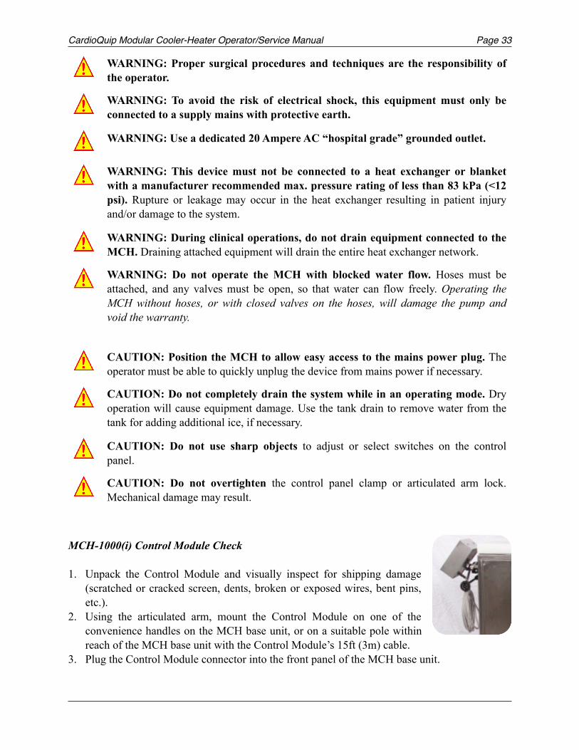
CardioQuip Modular Cooler-Heater Operator/Service Manual Page 33
MCH-1000(i) Control Module Check
1. Unpack the Control Module and visually inspect for shipping damage (scratched or cracked screen, dents, broken or exposed wires, bent pins, etc.).
2. Using the articulated arm, mount the Control Module on one of the convenience handles on the MCH base unit, or on a suitable pole within reach of the MCH base unit with the Control Module’s 15ft (3m) cable.
3. Plug the Control Module connector into the front panel of the MCH base unit.
WARNING: Proper surgical procedures and techniques are the responsibility of the operator.
WARNING: To avoid the risk of electrical shock, this equipment must only be connected to a supply mains with protective earth.
WARNING: Use a dedicated 20 Ampere AC “hospital grade” grounded outlet.
WARNING: This device must not be connected to a heat exchanger or blanket with a manufacturer recommended max. pressure rating of less than 83 kPa (<12 psi). Rupture or leakage may occur in the heat exchanger resulting in patient injury and/or damage to the system.
WARNING: During clinical operations, do not drain equipment connected to the MCH. Draining attached equipment will drain the entire heat exchanger network.
WARNING: Do not operate the MCH with blocked water flow. Hoses must be attached, and any valves must be open, so that water can flow freely. Operating the MCH without hoses, or with closed valves on the hoses, will damage the pump and void the warranty.
!
!
!
!
!
!
CAUTION: Position the MCH to allow easy access to the mains power plug. The operator must be able to quickly unplug the device from mains power if necessary.
CAUTION: Do not completely drain the system while in an operating mode. Dry operation will cause equipment damage. Use the tank drain to remove water from the tank for adding additional ice, if necessary.
CAUTION: Do not use sharp objects to adjust or select switches on the control panel.
CAUTION: Do not overtighten the control panel clamp or articulated arm lock. Mechanical damage may result.
!
!
!
!
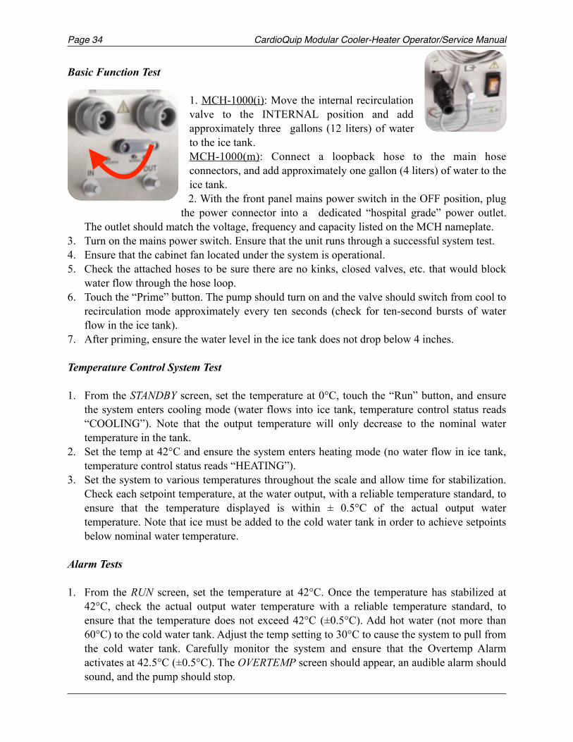
Page CardioQuip Modular Cooler-Heater Operator/Service Manual34
Basic Function Test 1. MCH-1000(i): Move the internal recirculation valve to the INTERNAL position and add approximately three gallons (12 liters) of water to the ice tank. MCH-1000(m): Connect a loopback hose to the main hose connectors, and add approximately one gallon (4 liters) of water to the ice tank. 2. With the front panel mains power switch in the OFF position, plug
the power connector into a dedicated “hospital grade” power outlet. The outlet should match the voltage, frequency and capacity listed on the MCH nameplate.
3. Turn on the mains power switch. Ensure that the unit runs through a successful system test. 4. Ensure that the cabinet fan located under the system is operational. 5. Check the attached hoses to be sure there are no kinks, closed valves, etc. that would block
water flow through the hose loop. 6. Touch the “Prime” button. The pump should turn on and the valve should switch from cool to
recirculation mode approximately every ten seconds (check for ten-second bursts of water flow in the ice tank).
7. After priming, ensure the water level in the ice tank does not drop below 4 inches.
Temperature Control System Test
1. From the STANDBY screen, set the temperature at 0°C, touch the “Run” button, and ensure the system enters cooling mode (water flows into ice tank, temperature control status reads “COOLING”). Note that the output temperature will only decrease to the nominal water temperature in the tank.
2. Set the temp at 42°C and ensure the system enters heating mode (no water flow in ice tank, temperature control status reads “HEATING”).
3. Set the system to various temperatures throughout the scale and allow time for stabilization. Check each setpoint temperature, at the water output, with a reliable temperature standard, to ensure that the temperature displayed is within ± 0.5°C of the actual output water temperature. Note that ice must be added to the cold water tank in order to achieve setpoints below nominal water temperature.
Alarm Tests
1. From the RUN screen, set the temperature at 42°C. Once the temperature has stabilized at 42°C, check the actual output water temperature with a reliable temperature standard, to ensure that the temperature does not exceed 42°C (±0.5°C). Add hot water (not more than 60°C) to the cold water tank. Adjust the temp setting to 30°C to cause the system to pull from the cold water tank. Carefully monitor the system and ensure that the Overtemp Alarm activates at 42.5°C (±0.5°C). The OVERTEMP screen should appear, an audible alarm should sound, and the pump should stop.
CardioQuip Modular Cooler-Heater Operator/Service Manual Page 35
2. Touch the “silence alarm” button. The audible alarm should silence for approximately 60 seconds, and the OVERTEMP screen should remain.
3. Touch and hold the cold water control button. The system should change to Low pump speed and water should flow into the cold water tank. Add cold water to the tank, and the alarm should clear. With hot water in the cold water tank, the alarm will not clear until the water temp in the tank falls below 42°C.
Terminating Operation
The “Standby” button can be used to access the STANDBY screen, which stops the pump and halts temperature control operations of the MCH. The mains power switch may be turned off at any time to completely terminate MCH operation. The set temperature and other operator-selectable settings are retained in the device’s memory.
Turning off the mains power switch isolates both poles (line and neutral) simultaneously from the supply mains. This may also be accomplished by unplugging the MCH power cord from the wall outlet.
Leakage Current Test
Using a calibrated electrical safety analyzer, measure electrical leakage current of the MCH unit under the following conditions: power on and off, polarity normal and reverse, unit grounded and ungrounded. The leakage current should be less than 100µA under all conditions. If a unit has leakage current that exceeds 100µA or has a significant increase in leakage current, the cause should be investigated. Refer to Underwriter’s Laboratory or IEC Standards to obtain the current and correct procedures for leakage current measurement.
Initial Cleaning
To prepare the MCH for storage or initial use, perform the Quarterly cleaning procedure, which may be found in the Maintenance section of this manual.
Page CardioQuip Modular Cooler-Heater Operator/Service Manual36
Normal Operation
WARNING: It is the operator’s responsibility to use, check, and maintain this device according to the labels of the product, accompanying instruction manuals, and any revisions of the labeling or instructions that may be subsequently issued.
WARNING: Proper surgical procedures and techniques are the responsibility of the operator.
WARNING: The MCH must be properly cleaned prior to operation or storage to prevent high bacterial count or residual chemicals.
WARNING: Use a dedicated 20 Ampere AC “hospital grade” grounded outlet.
WARNING: This device must not be connected to a heat exchanger or blanket with a manufacturer recommended max. pressure rating of less than 83 kPa (<12 psi). Rupture or leakage may occur in the heat exchanger resulting in patient injury and/or damage to the system.
WARNING: During clinical operations, do not drain equipment connected to the MCH. Draining attached equipment will drain the entire heat exchanger network.
WARNING: Do not operate the MCH with blocked water flow. Hoses must be attached, and any valves must be open, so that water can flow freely. Operating the MCH without hoses, or with closed valves on the hoses, will damage the pump and void the warranty.
WARNING: The use of high frequency (HF) surgical instruments or endocardial catheters with the MCH may increase the risk of electric shock, burns, or electromagnetic interference. Appropriate precautions should be taken to ensure operator and patient safety.
!
!
!
!
!
!
!
!
CAUTION: Position the MCH to allow easy access to the mains power plug. The operator must be able to quickly unplug the device from mains power if necessary.
CAUTION: Do not use sharp objects to adjust or select switches on the control panel.
CAUTION: Do not overtighten the control panel clamp or articulated arm lock on the MCH-1000(i). Mechanical damage may result.
CAUTION: Check for mechanical damage to any heat exchanger, blanket, or other applied part, prior to connecting it to the MCH.
!
!
!
!
CardioQuip Modular Cooler-Heater Operator/Service Manual Page 37
1. Attach the desired heat exchanger and/or blanket circuits to the appropriate connectors on the rear panel.
2. MCH-1000(i): Verify that the internal recirculation valve is in the NORMAL position. 3. Check the attached hoses to be sure there are no kinks, closed valves, etc. that would block
water flow through the hose loop. 4. Ensure that the cold water tank contains at least 4 inches of water, then add ice as desired.
The amount of ice needed to perform a given procedure is an operator decision; however, it is recommended that each procedure be started with a full supply (approximately 35 lbs. / 16 kg) of ice in the cold water tank. Note: The MCH-1000(m) holds significantly less ice than the MCH-1000(i).
5. With the front panel mains power switch in the “off” position, plug the power connector into a dedicated “hospital grade” power outlet. The outlet should match the voltage, frequency and capacity listed on the MCH nameplate.
6. Turn on the mains power switch and ensure that the unit runs through a successful system test.
7. Touch the “Prime” button to initiate the priming sequence. The pump should turn on and the valve should switch from cooling to recirculation mode approximately every ten seconds (check for ten-second bursts of water flow in the ice tank). Allow the system to prime until no air bubbles appear in the external water lines. The priming sequence will automatically run for 120 seconds, which should be sufficient for most applications.
8. Set the desired temperature setpoint. 9. Touch the “Run” button and monitor the water and patient temperature. Adjust the setpoint as
needed to maintain the desired patient temperature. 10. To halt operation, touch the “Standby” button.
11. If the water level in the tank is too high to accommodate additional ice, use the tank drain valve or the system drain to drain excess water from the cold water tank.
CAUTION: Do not operate the MCH with less than 4 inches of water in the cold water tank. Dry operation will cause equipment damage.!
WARNING: The MCH is not fully automatic. Monitoring of patient temperature and rate of temperature change remains the responsibility of the operator.!
Page CardioQuip Modular Cooler-Heater Operator/Service Manual38
High Temperature Alarm
If the output water temperature exceeds 42.5°C, the MCH will enter overtemp mode. The system pump will stop, the OVERTEMP screen will appear, and an audible alarm will sound. The operator should perform the following procedure to restore normal operation:
1. Touch the Silence Alarm button. The audible alarm will silence for approximately 60 seconds. This allows the operator to clear the overtemp condition without the distraction of an audible signal.
2. Touch and hold the cold water control button. The system will change to Low pump speed and into cool mode (water flow into ice tank), allowing cool water to flow into the system at a slow rate. The overtemp condition will clear when the water temperature decreases below 42°C.
3. Once the STANDBY screen appears, the operator can then check the temperature and pump settings, and touch the “Run” button to return to normal operation.
A Note About Flow
The main water pump used in the MCH is capable of delivering up to 60 liters per minute (LPM) of unrestricted flow at a maximum pressure of approximately 12 psi; however, the actual flow rate is ultimately determined by the combined restrictions of internal plumbing and external hoses, heat exchangers, patient blankets, etc. The internal restrictions of the MCH allow a typical maximum flow of approximately 20 LPM. Various configurations of hoses and heat exchangers will exhibit different flow rates. For example, when connected to a Medtronic MYOtherm™ or BIOtherm™ heat exchanger with the standard hose set, the typical range of flow is from 5 LPM at the lowest pump speed to 12 LPM at the highest pump speed.
WARNING: If the unit is in an overtemp condition and the emergency cool system is used, it is critical that the operator monitor the output water temperature.!
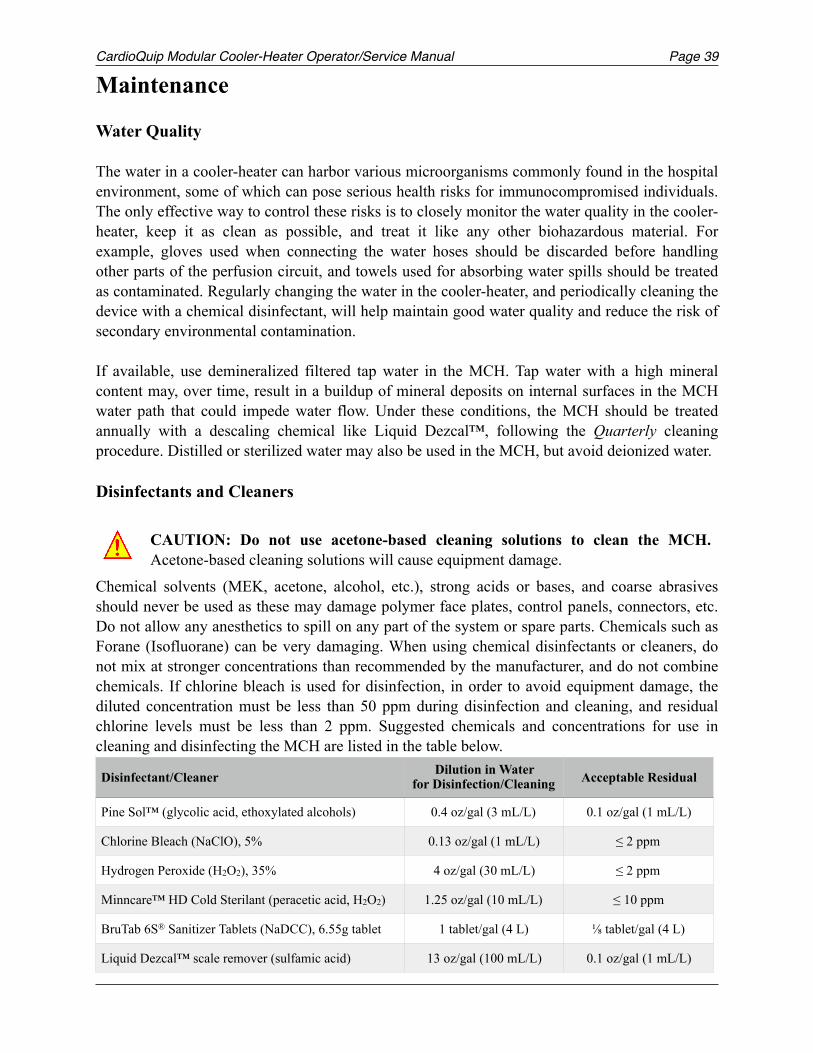
CardioQuip Modular Cooler-Heater Operator/Service Manual Page 39
Maintenance
Water Quality
The water in a cooler-heater can harbor various microorganisms commonly found in the hospital environment, some of which can pose serious health risks for immunocompromised individuals. The only effective way to control these risks is to closely monitor the water quality in the cooler-heater, keep it as clean as possible, and treat it like any other biohazardous material. For example, gloves used when connecting the water hoses should be discarded before handling other parts of the perfusion circuit, and towels used for absorbing water spills should be treated as contaminated. Regularly changing the water in the cooler-heater, and periodically cleaning the device with a chemical disinfectant, will help maintain good water quality and reduce the risk of secondary environmental contamination.
If available, use demineralized filtered tap water in the MCH. Tap water with a high mineral content may, over time, result in a buildup of mineral deposits on internal surfaces in the MCH water path that could impede water flow. Under these conditions, the MCH should be treated annually with a descaling chemical like Liquid Dezcal™, following the Quarterly cleaning procedure. Distilled or sterilized water may also be used in the MCH, but avoid deionized water.
Disinfectants and Cleaners
Chemical solvents (MEK, acetone, alcohol, etc.), strong acids or bases, and coarse abrasives should never be used as these may damage polymer face plates, control panels, connectors, etc. Do not allow any anesthetics to spill on any part of the system or spare parts. Chemicals such as Forane (Isofluorane) can be very damaging. When using chemical disinfectants or cleaners, do not mix at stronger concentrations than recommended by the manufacturer, and do not combine chemicals. If chlorine bleach is used for disinfection, in order to avoid equipment damage, the diluted concentration must be less than 50 ppm during disinfection and cleaning, and residual chlorine levels must be less than 2 ppm. Suggested chemicals and concentrations for use in cleaning and disinfecting the MCH are listed in the table below.
CAUTION: Do not use acetone-based cleaning solutions to clean the MCH. Acetone-based cleaning solutions will cause equipment damage.!
Disinfectant/Cleaner Dilution in Water for Disinfection/Cleaning Acceptable Residual
Pine Sol™ (glycolic acid, ethoxylated alcohols) 0.4 oz/gal (3 mL/L) 0.1 oz/gal (1 mL/L)
Chlorine Bleach (NaClO), 5% 0.13 oz/gal (1 mL/L) ≤ 2 ppm
Hydrogen Peroxide (H2O2), 35% 4 oz/gal (30 mL/L) ≤ 2 ppm
Minncare™ HD Cold Sterilant (peracetic acid, H2O2) 1.25 oz/gal (10 mL/L) ≤ 10 ppm
BruTab 6S® Sanitizer Tablets (NaDCC), 6.55g tablet 1 tablet/gal (4 L) ⅛ tablet/gal (4 L)
Liquid Dezcal™ scale remover (sulfamic acid) 13 oz/gal (100 mL/L) 0.1 oz/gal (1 mL/L)
Page CardioQuip Modular Cooler-Heater Operator/Service Manual40
After Every Use
Clean all surfaces of the MCH to remove any splattered blood or spilled liquids. Dishwashing liquid and mild liquid disinfectants can generally be used, but cloths and sponges should be wrung dry to prevent excess liquid from getting inside components. To clean the control panel, use ordinary household dish washing liquid in a wet cotton cloth wrung dry. Use only products and processes that are suitable for plastic surfaces. Avoid excess water near the control panel.
Weekly
The water tank should be inspected at least weekly to assess the condition of the water. If the water contains solids or debris, or emits a foul smell, drain the water from the system and perform the Quarterly cleaning procedure.
Quarterly
To ensure proper operation of the MCH, perform the Initial Operation Check at least quarterly. The water tank should be disinfected at least quarterly to prevent excessive bacteria buildup within the unit, and to remove accumulated solids and debris. Follow the procedure below:
1. Attach the hoses with a loopback connector (or set the recirculation valve to INTERNAL, if so equipped) and put approximately six inches of water in the water tank.
2. With the front panel mains power switch turned off, plug the power connector into a dedicated “hospital grade” AC power outlet. The outlet should match the voltage, frequency and capacity listed on the MCH nameplate.
3. Turn on the mains power switch for the MCH. Ensure that the unit runs through a successful system test.
4. Touch the “Prime” button to initiate the priming sequence. The pump should turn on at full speed, and the valve should switch from “COOLING” to “RECIRC” approximately every ten seconds (check for ten-second bursts of water flow in the water tank).
5. After priming, ensure the water level in the ice tank does not drop below four inches. 6. Add the selected cleaning chemical to the cold water tank at the manufacturer’s
recommended rates (see chart above for recommendations). Once primed, and with six inches of water in the tank, the MCH-1000(i) contains approximately three gallons (12 liters) of water, and the MCH-1000(m) contains approximately 1 gallon (4 liters) of water.
WARNING: The MCH must be disconnected from electrical power before inspecting, cleaning, or preparing the device for use.
CAUTION: Cleaning and disinfection policies and procedures must follow current FDA and CDC guidance.
!
!
CAUTION: Do not operate the MCH with less than 4 inches of water in the cold water tank. Dry operation will cause equipment damage.!
CardioQuip Modular Cooler-Heater Operator/Service Manual Page 41
7. Run the MCH through five (5) standard priming cycles, or one extended priming cycle, to fully mix and circulate the cleaning chemical (10 minutes total). At some point during this step, set the recirculation valve (if so equipped) to INTERNAL for at least 10-15 seconds, to ensure that disinfectant reaches all sections of the internal plumbing.
8. Scrub the cold water tank and outlet screens with a nylon brush. It is imperative that the tank and screens be thoroughly cleaned to ensure disinfection. The screens may be unscrewed and removed to assist in cleaning. Be sure to replace the screens before operating the MCH.
9. Open the system and tank drain valves and drain the unit completely. With the drain valves open, flush the unit with clean water.
10. Close the drain valves and fill the cold water tank to maximum level. Run the MCH through a priming cycle to flush residual cleaning chemical from the system.
11. Turn off the mains power switch, and drain the system completely. If necessary, repeat the flushing sequence until all cleaning chemical is removed from the system.
12. With a brush, clean the fan guard and air intake grille on the underside of the unit. All debris should be removed so that air flow is not impeded.
13. Inspect all plastic tubing on the hose kits. Any tubing that is clouded and/or has lost its flexibility should be replaced.
14. Perform the cleaning procedure listed under After Every Use. The system can now be returned to use or stored. Always store the system drained and dry.
Annually
The MCH should receive a complete preventive maintenance service check by an authorized CardioQuip service technician every 12 months. The Annual Preventive Maintenance Checklist at the end of this manual may be used by qualified biomedical personnel to verify essential performance and safety of the MCH.
If tap water with a high mineral content is used in the MCH, or if mineral deposits are noticed in the MCH water path, then the device should be treated annually with a descaling chemical like Liquid Dezcal™, using the Quarterly cleaning procedure. Do not mix the Dezcal with other chemicals or disinfectants.
Disposal Procedures
Dispose of water drained from the MCH using a standard facility, floor, or greywater drain. Prior to disposing of the MCH itself (via sale, transfer, recycling, etc.), the Quarterly maintenance procedures should be performed and the MCH prepared for storage. Internal components of the MCH and its modules may contain trace amounts of lead or other toxic substances. When discarding the MCH or any of its modules, consult local regulations regarding the disposal of used electronics and medical equipment.
CAUTION: Use only hospital-approved bactericidal agents that are non-acidic and non-foaming. Operation with unapproved agents may cause equipment damage.!
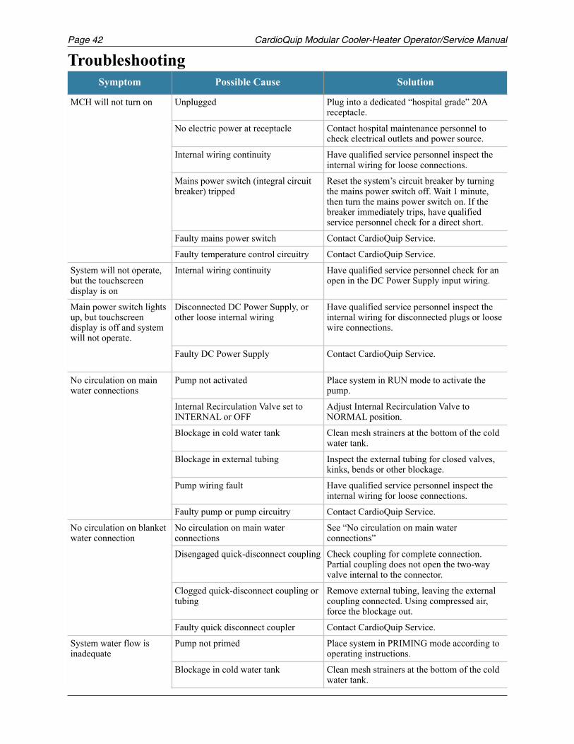
Page CardioQuip Modular Cooler-Heater Operator/Service Manual42
TroubleshootingSymptom Possible Cause Solution
MCH will not turn on Unplugged Plug into a dedicated “hospital grade” 20A receptacle.
No electric power at receptacle Contact hospital maintenance personnel to check electrical outlets and power source.
Internal wiring continuity Have qualified service personnel inspect the internal wiring for loose connections.
Mains power switch (integral circuit breaker) tripped
Reset the system’s circuit breaker by turning the mains power switch off. Wait 1 minute, then turn the mains power switch on. If the breaker immediately trips, have qualified service personnel check for a direct short.
Faulty mains power switch Contact CardioQuip Service.
Faulty temperature control circuitry Contact CardioQuip Service.
System will not operate, but the touchscreen display is on
Internal wiring continuity Have qualified service personnel check for an open in the DC Power Supply input wiring.
Main power switch lights up, but touchscreen display is off and system will not operate.
Disconnected DC Power Supply, or other loose internal wiring
Have qualified service personnel inspect the internal wiring for disconnected plugs or loose wire connections.
Faulty DC Power Supply Contact CardioQuip Service.
No circulation on main water connections
Pump not activated Place system in RUN mode to activate the pump.
Internal Recirculation Valve set to INTERNAL or OFF
Adjust Internal Recirculation Valve to NORMAL position.
Blockage in cold water tank Clean mesh strainers at the bottom of the cold water tank.
Blockage in external tubing Inspect the external tubing for closed valves, kinks, bends or other blockage.
Pump wiring fault Have qualified service personnel inspect the internal wiring for loose connections.
Faulty pump or pump circuitry Contact CardioQuip Service.
No circulation on blanket water connection
No circulation on main water connections
See “No circulation on main water connections”
Disengaged quick-disconnect coupling Check coupling for complete connection. Partial coupling does not open the two-way valve internal to the connector.
Clogged quick-disconnect coupling or tubing
Remove external tubing, leaving the external coupling connected. Using compressed air, force the blockage out.
Faulty quick disconnect coupler Contact CardioQuip Service.
System water flow is inadequate
Pump not primed Place system in PRIMING mode according to operating instructions.
Blockage in cold water tank Clean mesh strainers at the bottom of the cold water tank.
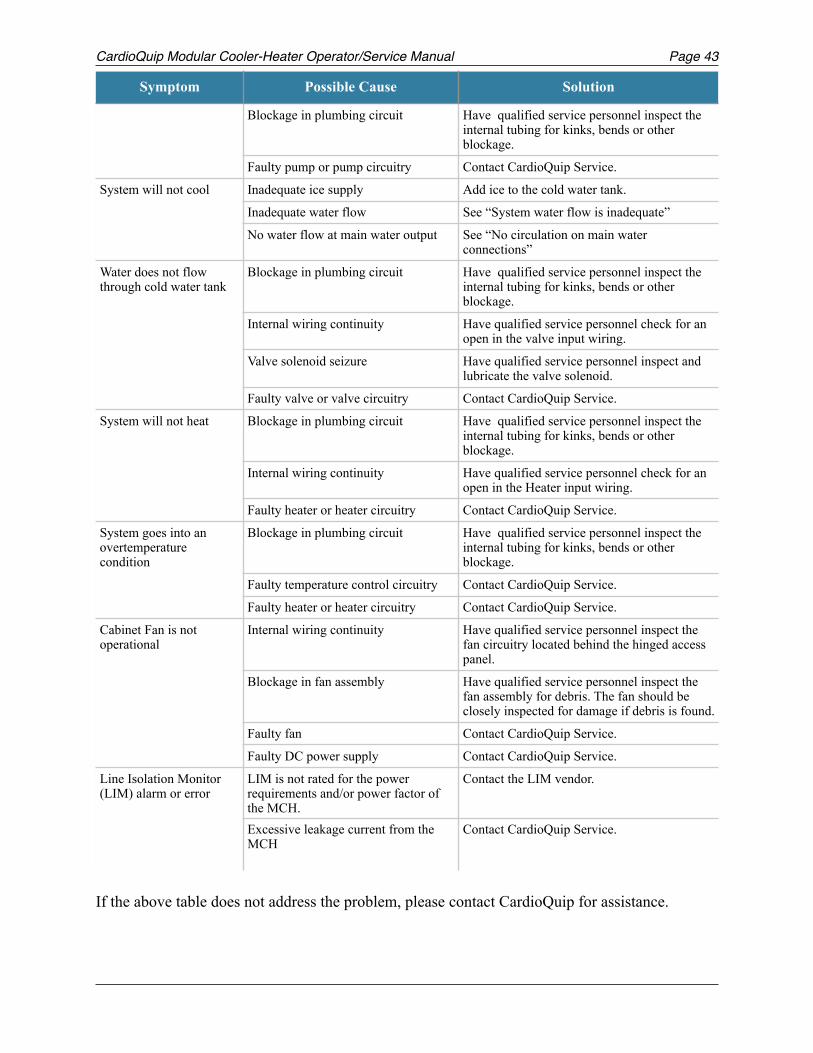
CardioQuip Modular Cooler-Heater Operator/Service Manual Page 43
If the above table does not address the problem, please contact CardioQuip for assistance.
Blockage in plumbing circuit Have qualified service personnel inspect the internal tubing for kinks, bends or other blockage.
Faulty pump or pump circuitry Contact CardioQuip Service.
System will not cool Inadequate ice supply Add ice to the cold water tank.
Inadequate water flow See “System water flow is inadequate”
No water flow at main water output See “No circulation on main water connections”
Water does not flow through cold water tank
Blockage in plumbing circuit Have qualified service personnel inspect the internal tubing for kinks, bends or other blockage.
Internal wiring continuity Have qualified service personnel check for an open in the valve input wiring.
Valve solenoid seizure Have qualified service personnel inspect and lubricate the valve solenoid.
Faulty valve or valve circuitry Contact CardioQuip Service.
System will not heat Blockage in plumbing circuit Have qualified service personnel inspect the internal tubing for kinks, bends or other blockage.
Internal wiring continuity Have qualified service personnel check for an open in the Heater input wiring.
Faulty heater or heater circuitry Contact CardioQuip Service.
System goes into an overtemperature condition
Blockage in plumbing circuit Have qualified service personnel inspect the internal tubing for kinks, bends or other blockage.
Faulty temperature control circuitry Contact CardioQuip Service.
Faulty heater or heater circuitry Contact CardioQuip Service.
Cabinet Fan is not operational
Internal wiring continuity Have qualified service personnel inspect the fan circuitry located behind the hinged access panel.
Blockage in fan assembly Have qualified service personnel inspect the fan assembly for debris. The fan should be closely inspected for damage if debris is found.
Faulty fan Contact CardioQuip Service.
Faulty DC power supply Contact CardioQuip Service.
Line Isolation Monitor (LIM) alarm or error
LIM is not rated for the power requirements and/or power factor of the MCH.
Contact the LIM vendor.
Excessive leakage current from the MCH
Contact CardioQuip Service.
Symptom Possible Cause Solution
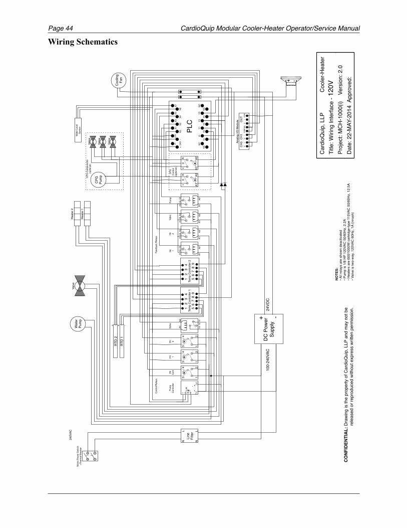
Page CardioQuip Modular Cooler-Heater Operator/Service Manual44
Wiring Schematics
!
-+DC
Pow
er
Supp
ly10
0-24
0VAC
24VD
C
+ - -RT
D 1
+ - -RT
D 2
Wat
er L
evel
Se
nsor
Feed
back
Rel
ays
Pum
pCo
ntro
ller
21
43
A1A2
1112
14
A1A2
1112
14
A1A2
1112
14
A1A2
1112
14
Wat
erPu
mp
Cool
ing
Fan
Y0Y2
Y4NC
Y1Y3
Y5NC
NC
NC
V+
V-
+ 2
4V -
X0X2
X4X6
X1X3
X5X7
COM
PLC
CONF
IDEN
TIAL
: Dra
wing
is th
e pr
oper
ty o
f Car
dioQ
uip,
LLP
and
may
not
be
rele
ased
or r
epro
duce
d wi
thou
t exp
ress
writ
ten
perm
issio
n.
Card
ioQ
uip,
LLP
Coo
ler-H
eate
rTi
tle: W
iring
Inte
rface
-Pr
ojec
t: M
CH-1
000(
i)
Vers
ion:
2.0
Date
: 22-
MAY
-201
4 A
ppro
ved:-+
Heat
er 2
Heat
er 1
Valve
1 2
3
4Te
mp
Cont
rolle
r 25
6 7
8 9
Tem
p Co
ntro
ller 1
1 2
3
4
5 6
7 8
9
Anal
og I/
O M
odul
e
V
I
V
ICO
M S
EL
V
I
CO
MCH
0CH
1O
UT
1 T1L1
2 3 4
Htr 1
Htr 2
Valve
A2A1
1112
14
Valve
Htr
Com
Htr 1
Htr 2
Pum
p
Cont
rol R
elay
s
+A
A1A2
0+
A
A1A2
0
CPG
Cont
rol
(opt
iona
l)
21
43
21
43
Line
Filte
r LN
LN
Mai
ns P
ower
Sw
itch
+The
rmal
Bre
aker
CPG
Pum
p
Valve
Valve
Valve
CPG
Com
pone
nts
(opt
iona
l)
NOTE
S:• A
ll rel
ays
are
show
n de
activ
ated
• Pum
p is
1/8
HP 1
20VA
C 50
/60H
z, 2
.2A
• Hea
ters
are
600
/100
0W c
artri
dge-
type
115
VAC
50/6
0Hz,
12.
5A• V
alve
is tw
o-wa
y, 12
0VAC
60H
z, 1
A (in
rush
)
120V
240V
AC
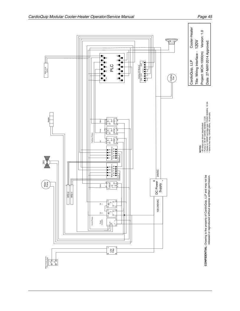
CardioQuip Modular Cooler-Heater Operator/Service Manual Page 45
!
-+DC
Pow
er
Supp
ly10
0-24
0VAC
24VD
C
+ - -RT
D 1
+ - -RT
D 2
Wat
er L
evel
Se
nsor
Feed
back
Rel
ays
Pum
pCo
ntro
ller
21
43
A1A2
1112
14
A1A2
1112
14
A1A2
1112
14
Wat
erPu
mp
Cool
ing
Fan
Y0Y2
Y4NC
Y1Y3
Y5NC
NC
NC
V+
V-
+ 2
4V -
X0X2
X4X6
X1X3
X5X7
COM
PLC
-+
Heat
er
Valve
1 2
3
4Te
mp
Cont
rolle
r 25
6 7
8 9
Tem
p Co
ntro
ller 1
1 2
3
4
5 6
7 8
9
Anal
og I/
O M
odul
e
V
I
V
ICO
M S
EL
V
I
CO
MCH
0CH
1O
UT
1 T1L1
2 3 4
Htr
Valve
A2A1
1112
14
Valve
Htr N
Htr L
Pum
p
Cont
rol R
elay
s
21
43
Line
Filte
r LN
LN
Mai
ns P
ower
Sw
itch
+The
rmal
Bre
aker
CONF
IDEN
TIAL
: Dra
wing
is th
e pr
oper
ty o
f Car
dioQ
uip,
LLP
and
may
not
be
rele
ased
or r
epro
duce
d wi
thou
t exp
ress
writ
ten
perm
issio
n.
Card
ioQ
uip,
LLP
Coo
ler-H
eate
rTi
tle: W
iring
Inte
rface
-Pr
ojec
t: M
CH-1
000(
m)
Ver
sion:
1.0
Date
: 27-
MAY
-201
4 Ap
prov
ed:
NOTE
S:• A
ll rel
ays
are
show
n de
activ
ated
• Pum
p is
1/8
HP 1
20VA
C 50
/60H
z, 2
.2A
• Hea
ter i
s 16
00W
car
tridg
e-ty
pe 1
15VA
C 50
/60H
z, 1
2.5A
• Val
ve is
two-
way,
120V
AC 6
0Hz,
1A
(inru
sh)
120V
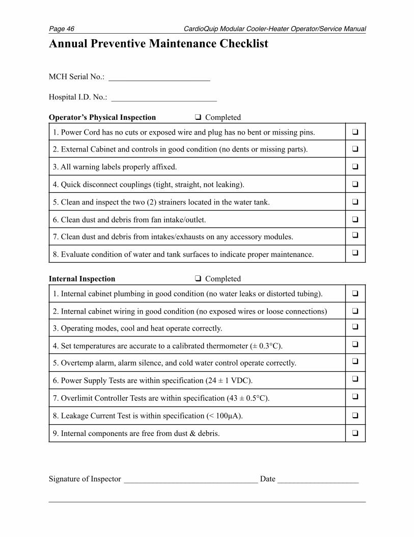
Page CardioQuip Modular Cooler-Heater Operator/Service Manual46
Annual Preventive Maintenance Checklist
MCH Serial No.: _________________________
Hospital I.D. No.: __________________________
Operator’s Physical Inspection Completed
Internal Inspection Completed
Signature of Inspector _________________________________ Date ____________________
1. Power Cord has no cuts or exposed wire and plug has no bent or missing pins.
2. External Cabinet and controls in good condition (no dents or missing parts).
3. All warning labels properly affixed.
4. Quick disconnect couplings (tight, straight, not leaking).
5. Clean and inspect the two (2) strainers located in the water tank.
6. Clean dust and debris from fan intake/outlet.
7. Clean dust and debris from intakes/exhausts on any accessory modules.
8. Evaluate condition of water and tank surfaces to indicate proper maintenance.
1. Internal cabinet plumbing in good condition (no water leaks or distorted tubing).
2. Internal cabinet wiring in good condition (no exposed wires or loose connections)
3. Operating modes, cool and heat operate correctly.
4. Set temperatures are accurate to a calibrated thermometer (± 0.3°C).
5. Overtemp alarm, alarm silence, and cold water control operate correctly.
6. Power Supply Tests are within specification (24 ± 1 VDC).
7. Overlimit Controller Tests are within specification (43 ± 0.5°C).
8. Leakage Current Test is within specification (< 100µA).
9. Internal components are free from dust & debris.