Embed Size (px)
Citation preview


McELROY BEGAN
www.mcelroyfintube.com2 HISTORY OF McELROY
operations in the 1950’s and has grown from a two person startup in an Oklahoma garage, to the industry leader in the design and manufacture of machinery to produce finned tubes. Our first finning equipment was introduced in 1961 and has evolved to the digitally controlled No. 5 Machine which includes many labor saving options to simplify and reduce the cost of the cus-tomer’s plant operations. The name McElroy is recognized worldwide as the most reliable, rugged, versatile, and technically advanced equipment in the marketplace.
McElroy’s focus on innovation has further driven our growth. We have expanded countless times over our 60 years in business. Each expansion had one primary aim—gain physical space needed to bring our inventions to life and better meet our customers’ demands. We currently have over 575,000 sq. ft. of manufacturing and office space spread across 25 acres.
In addition to our new facility, we are in the final stages of a multimillion dollar renovation to our existing facilities. The Fintube assembly area has undergone physical upgrades to improve our operations and increase our capacity.
Our investment in the state-of-the-art technology and commitment to quality work translates into productivity in your plant. Our commitment to stand behind our equipment and our cus-tomers remains steadfast.
Since 2012 McElroy finned tube products are offered through our expanding international net-work of offices. Machines, service, technical assistance and training are available through selected strategic offices.
McElroy provides information on our products, animations on the formation of different types of fins, videos and acceptable industry practices for different finned tubes through our website and mobile apps. For more information visit www.mcelroyfintube.com

TABLE OF CONTENTS
APPLIEDTU
BE
HAR
DW
ARE
WR
AP-ON
OVERLAPPED
FOO
TEDK
NU
RLED
FOO
TEDIM
BED
DED
PERFO
RATED
APPLIEDR
EFEREN
CEEXTR
UD
EDEXTR
UD
EDTO
OLIN
GEXTR
UD
EDR
EFEREN
CE
www.mcelroyfintube.com TABLE OF CONTENTS 3
Perforated Fin Enhancement HardwareWrap-On Perforated Fin Height HardwareOverlapped Footed Perforated Fin Height HardwareEnhanced Imbedded Perforated FinApplied Machine Reference Guide
EXTRUDED FINTUBEModel B Extruded Machine Key PartsExtruded Additional EquipmentExtruded End-User ResponsibilitiesExtruded Mandatory Machine SparesExtruded Typical Production RateExtruded Tube Cleaning Line ToolingExtruded Input Rack ToolingExtruded Finning Head ToolingExtruded Finned Tube Rack ToolingExtruded End Stripper ToolingExtruded Pitch(FPI) ToollingExtruded Machine Reference GuideTooling for Previous Models
INTRODUCTIONWarrantySafety & QualityThe McElroy AdvantageMcElroy TrainingMajor Fin Type Comparison
APPLIED FINTUBENo. 5 Machine Key PartsNo. 5 Mandatory Machine SparesNo. 5 Oil SpecificationsNo. 5 Typical Production Rates of Wrap-On & Imbedded FinsNo. 5 Additional EquipmentNo. 5 End-User ResponsibilitiesNo. 5 Machine Selection ProcessTube Size HardwareWrap-On Fin Height HardwareOverlapped Footed Fin Height HardwareKnurled Footed Fin Height HardwareWrap-On Knurled Footed Fin Pitch HardwareOverlapped Footed Knurled Fin Pitch HardwareImbedded Fin Height HardwareImbedded Fin Plow Groover SystemImbedded Carbon Steel FinImbedded Stainless Steel Fin
244556
91214151617181920273747495255626371
7576828793
105107108109110112113113114114115115119123

WARRANTY
APPL
IED
TUB
EH
ARD
WAR
EW
RAP
-ON
OVER
LAPP
EDFO
OTE
DK
NU
RLE
DFO
OTE
DIM
BED
DED
PER
FOR
ATED
APPL
IED
REF
EREN
CEEX
TRU
DED
EXTR
UD
EDTO
OLI
NG
EXTR
UD
EDR
EFER
ENCE
www.mcelroyfintube.com4 WARRANTY INFORMATION
McElroy Manufacturing, Inc. warrants these products, Ex Works from Tulsa, Oklahoma, for 12 months from date of shipment against faulty material or workmanship, except for normal wear and abuse, with the exception of purchased items in which case that manufacturer’s warranty applies.
McElroy further warrants the machine to produce the tube sizes and fin heights as stated when commissioning and training of personnel are conducted by McElroy technicians and the subsequent maintenance and repairs are made in compliance with McElroy specifications.
McElroy further warrants on the No. 5 machine, that finning speed with aluminum fin is 75% of maximum tube speed (RPM) for Wrap-On fin and 50% of maximum tube speed (RPM) for Imbedded aluminum fins on carbon steel tube when recommended coolant, lubricants, and materials are used.
DISCLAIMER OF LIABILITYMcElroy accepts no responsibility of liability for finned tubes. Operation and maintenance of the product is the responsibility
of others. We recommend qualified procedures be followed when using McElroy fintube equipment. McElroy makes no other warranty of any kind whatsoever, express or implied; and all implied warranties of merchantability and fitness for a par-ticular purpose which exceed the afore stated obligation are hereby disclaimed by McElroy.
PRODUCT IMPROVEMENT McElroy reserves the right to make any changes in or improvements on its products without incurring any liability or obligation
to update or change previously sold machines and/or the accessories thereto.
INFORMATION DISCLOSED No information of knowledge heretofore or hereafter disclosed to McElroy in the performance of or in connection with the
terms hereof, shall be deemed to be confidential or proprietary, unless otherwise expressly agreed to in writing by McElroy and any such information or knowledge shall be free from restrictions, other than a claim for patent infringement, is part of the con-sideration hereof.
PROPRIETARY RIGHTS All proprietary rights pertaining to the equipment or the components of the equipment to be delivered by McElroy hereunder,
and all patent rights therein, arising prior to, or in the course of, or as a result of the design or fabrication of the said product, are exclusively the property of McElroy.
LAW APPLICABLE All sales shall be governed by the Uniform Commercial Code of Oklahoma, U.S.A.
McELROY APPLIED TUBE FINNING MACHINES SAFETY
& QUALITYMcELROY QUALITY
McElroy is dedicated to Total Quality Management throughout the organization. Processes and procedures are documented utilizing our McElroy “SP” (Standard Practice) and “ES” (Engineering Standard) system. Building on our doctrine of empowerment, each process/procedure is the specific responsibility of the team member that performs the task.
Conformance to our Standards is the minimum require-ment for any member of McElroy; and it is what allows us as a Company to consistently deliver products that provide the highest quality and performance in the industry.
Specific machine directives available upon request. Safety standards and declaration of conformity are available upon request.
McELROY SAFETYAt McElroy, your safety is our number one priority. All
of our equipment, literature and training classes are strictly designed with the operator’s safety in mind. Never operate machinery until you have read the manual completely and understand the safety and operation sections of your man-ual. Your safety and the safety of others depends upon care and judgment in the operation of the equipment. Product manuals and assembly drawings are provided to each end user and additional copies can be requested from your prod-uct specialist.

THE McELROY ADVANTAGE
APPLIEDTU
BE
HAR
DW
ARE
WR
AP-ON
OVERLAPPED
FOO
TEDK
NU
RLED
FOO
TEDIM
BED
DED
PERFO
RATED
APPLIEDR
EFEREN
CEEXTR
UD
EDEXTR
UD
EDTO
OLIN
GEXTR
UD
EDR
EFEREN
CE
www.mcelroyfintube.com THE McELROY ADVANTAGE 5
McElroy understands that a fully trained and qualified operator can increase your overall production and your bot-tom line. That’s why McElroy offers basic training, periodic machine re-inspection, and refresher courses to ensure the efficiency, productivity and safety of your equipment and personnel through McElroy University.
OPERATOR TRAININGOperators can be trained in our facility or yours. Our
hands on training helps operators of all levels to understand the principles of the machine and the skills necessary to pro-duce products from our equipment. With an instructional mix of classroom and hands-on, operators learn not only the basic mechanics of the machine operations but the theory behind it for an overall understanding of proper finning. Maintenance and troubleshooting are also included.
Our manuals and operator screens are offered in multiple languages to help facilitate the professional training and education of your management and staff.
ONLINE TRAININGFor existing customers in need of a quick refresher,
or training of a new operator, visit our website at www.mcelroyfintube.com for short video clips of key set up and operational requirements.
TRAINING
PRODUCTIVITYThe McElroy family of finned tube machinery offers the highest productivity in the market. From handling the raw materials to the final
finned tube production, McElroy productivity offers saving in both labor and time, thus improving your profitability.
VERSATILITYThe Applied family of machines offers the end user the versatility to produce a wide range of types and sizes of finned tubes. With
the base machine, tooling can be added at any time to produce these different configurations of fins: Wrap-On, Overlapped Footed Fin, Wrap-On Knurled Footed Fin, Overlapped Knurled Footed Fin, Imbedded Fin and Perforated Fin.
The Extruded family of products offers a range of tube sizes. With our standard discs, the end user can produce fins with a minimum fin height of 0.5” (12.7mm) to a maximum of 0.625” (15.9mm.)
QUALITYOur equipment is designed to give you the assurance that your produced tube will meet industry acceptable standards and quality. Our tooling,
training, and continual support of our customer base assures you that the brand McElroy is known and respected throughout the world.
DURABILITY & PERFORMANCEMcElroy prides itself on building the toughest and longest lasting fintube machines in the world. With proper maintenance, many
McElroy machines built in the 1960’s are still operating today. They are designed to be used anywhere in the world and are configured to meet each customer’s specific requirements. Equipment is designed to require minimal, but regular maintenance and critical com-ponents are designed to last for years.
MANAGEMENT REPORTINGThis is a system used to record and document the daily activities of your operator and daily production. In addition, the informa-
tion can be downloaded in Excel format for interpretation and use in determining your production costs and ultimate bid pricing. The management reporting feature is available on the No. 5 machine. It is recommended that each tube configuration be assigned a part number which allows the end user to have specific productivity information for each configuration. In addition, the machine stores critical machine settings for ease of set up for the next production run for the specific part number.
COMPLETE TUBE-HANDLING SYSTEMWhether you select the Applied No. 5 Machine or our Extruded Machine, we offer complete handling of the tube from the time it
is loaded into the machine until it is ready for offloading to the finished basket and for transport to your assembly area or to your end customer.
INTERNATIONAL PRESENCEMcElroy always strives to provide customer focused service. We pride ourselves on being easily accessible to our customers through
our headquarters and now through our international locations. Machines, service, technical assistance and training are available through selected strategic offices.
MAJOR FIN TYPESJAP
PLIE
DTU
BE
HAR
DW
ARE
WR
AP-O
NOV
ERLA
PPED
FOO
TED
KN
UR
LED
FOO
TED
IMB
EDD
EDPE
RFO
RAT
EDAP
PLIE
DR
EFER
ENCE
EXTR
UD
EDEX
TRU
DED
TOO
LIN
GEX
TRU
DED
REF
EREN
CE
www.mcelroyfintube.com6 MAJOR FIN TYPES
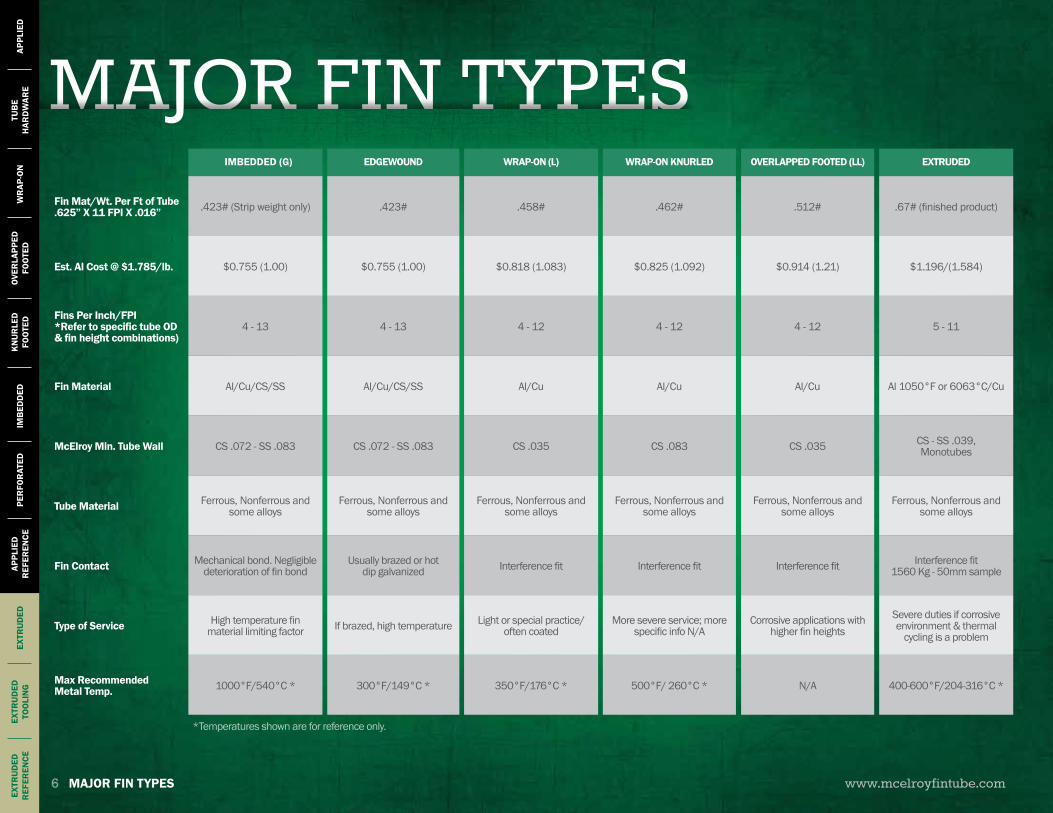
IMBEDDED (G) EDGEWOUND WRAP-ON (L) WRAP-ON KNURLED OVERLAPPED FOOTED (LL) EXTRUDED
Fin Mat/Wt. Per Ft of Tube.625” X 11 FPI X .016” .423# (Strip weight only) .423# .458# .462# .512# .67# (finished product)
Est. Al Cost @ $1.785/lb. $0.755 (1.00) $0.755 (1.00) $0.818 (1.083) $0.825 (1.092) $0.914 (1.21) $1.196/(1.584)
Fins Per Inch/FPI *Refer to specific tube OD & fin height combinations)
4 - 13 4 - 13 4 - 12 4 - 12 4 - 12 5 - 11
Fin Material Al/Cu/CS/SS Al/Cu/CS/SS Al/Cu Al/Cu Al/Cu Al 1050°F or 6063°C/Cu
McElroy Min. Tube Wall CS .072 - SS .083 CS .072 - SS .083 CS .035 CS .083 CS .035 CS - SS .039, Monotubes
Tube Material Ferrous, Nonferrous and some alloys
Ferrous, Nonferrous and some alloys
Ferrous, Nonferrous and some alloys
Ferrous, Nonferrous and some alloys
Ferrous, Nonferrous and some alloys
Ferrous, Nonferrous and some alloys
Fin Contact Mechanical bond. Negligible deterioration of fin bond
Usually brazed or hot dip galvanized Interference fit Interference fit Interference fit Interference fit
1560 Kg - 50mm sample
Type of Service High temperature fin material limiting factor If brazed, high temperature Light or special practice/
often coatedMore severe service; more
specific info N/ACorrosive applications with
higher fin heightsSevere duties if corrosive environment & thermal
cycling is a problem
Max RecommendedMetal Temp. 1000°F/540°C * 300°F/149°C * 350°F/176°C * 500°F/ 260°C * N/A 400-600°F/204-316°C *
*Temperatures shown are for reference only.
www.mcelroyfintube.com
APPLIEDTU
BE
HAR
DW
ARE
WR
AP-ON
OVERLAPPED
FOO
TEDK
NU
RLED
FOO
TEDIM
BED
DED
PERFO
RATED
APPLIEDR
EFEREN
CEEXTR
UD
EDEXTR
UD
EDTO
OLIN
GEXTR
UD
EDR
EFEREN
CE
7
www.mcelroyfintube.com
APPL
IED
TUB
EH
ARD
WAR
EW
RAP
-ON
OVER
LAPP
EDFO
OTE
DK
NU
RLE
DFO
OTE
DIM
BED
DED
PER
FOR
ATED
APPL
IED
REF
EREN
CEEX
TRU
DED
EXTR
UD
EDTO
OLI
NG
EXTR
UD
EDR
EFER
ENCE
8
THEORY OFAPPLIED FINTUBE
APPLIED FINTUBE 9
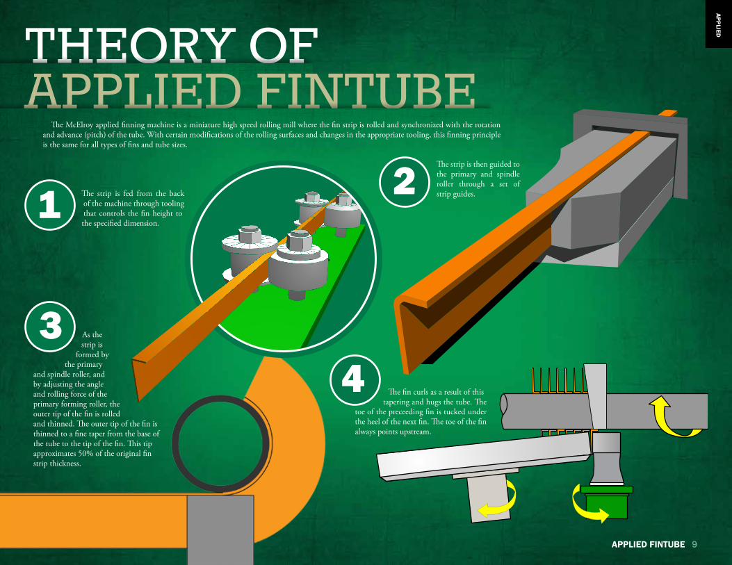
The McElroy applied finning machine is a miniature high speed rolling mill where the fin strip is rolled and synchronized with the rotation and advance (pitch) of the tube. With certain modifications of the rolling surfaces and changes in the appropriate tooling, this finning principle is the same for all types of fins and tube sizes.
As the strip is
formed by the primary
and spindle roller, and by adjusting the angle and rolling force of the primary forming roller, the outer tip of the fin is rolled and thinned. The outer tip of the fin is thinned to a fine taper from the base of the tube to the tip of the fin. This tip approximates 50% of the original fin strip thickness.
2
34
The strip is then guided to the primary and spindle roller through a set of strip guides.
The fin curls as a result of this tapering and hugs the tube. The toe of the preceeding fin is tucked under the heel of the next fin. The toe of the fin always points upstream.
The strip is fed from the back of the machine through tooling that controls the fin height to the specified dimension.
1
APPLIED

NO.5 APPLIED MACHINE
www.mcelroyfintube.com10 NO. 5 APPLIED MACHINE
APPL
IED
UNIQUE IN THE INDUSTRYEFFICIENT USE OF FIN STRIP
Our machines work the fin strip so that the fin shape is thick at the bottom and thin at the tip. This uses less aluminum than simply wrapping the aluminum around the tube. Weight per foot is reduced, as is raw material cost.
HIGH SPEED PRODUCTIONThe No.5 typically runs at approximately 2,400 rpm yielding high productivity rates. There
is a maximum of 3000 rpm on a 1” tube.
DIGITAL ELECTRONIC COMPONENTSOur digital drive system increases the accuracy of the finning process generating a higher
quality product and more consistent results. Digital controls also allow for a wider range of FPI capabilities. Operation parameters can be saved as unique part numbers for easy access.
SMART CARD LOGICThe smart card logic system allows for easy programming upgrades, as they become available,
and easy access to a backup program.
SIMPLIFIED MAINTENANCE PROCEDURESDual digital-drive motors eliminate speed variators, variable pulley systems and belt systems.
Fewer gearboxes and shafts means less maintenance.
QUIETER OPERATIONWith fewer gear drive components and the elimination of jack shafts, the machine operation
becomes quieter and mechanically simpler.
SIMPLIFIED MANAGEMENT REPORTING The management reporting allows production supervisors to have access to a detailed look at
production numbers and efficiency. This will assist the user to maximize capabilities.

NO.5 APPLIED MACHINEFor saw-ready machines, a second transformer may be required. Please consult your McElroy
representative.
www.mcelroyfintube.com NO. 5 APPLIED MACHINE 11
APPLIED
NO. 5 MACHINE CAPABILITIESTube Size: 0.5” – 2” (12.7mm – 50.8mm)Fin Heights: 0.25” – 1” (6.35mm – 25.4mm)Fins Per Inch (FPI): 4 – 13
FIN TYPES• Knurled Footed (KL-Fin)• Overlapped Footed (LL-Fin)• Imbedded (G-Fin)• Wrap-on (L-Fin)• Perforated
ADDITIONAL CAPABILITIESThe No.5 Applied Fintube Machine also has the capability of applying 0.625” carbon steel imbedded fins on 1” and larger tube sizes, as well as 0.375” high stainless steel imbedded fin.
CUSTOM MODIFICATIONSOther configurations may be available upon request.
NO. 5 MACHINE SPECS.LENGTH: 30.5 meters (100 feet)
WIDTH: 6.10 meters (20 feet)
TYPICAL TUBE LENGTH: 12.19 meters (40 feet)Other rack lengths are also available
POWER REQUIREMENT: 100 Amps at 460 Volts, 3 Phase
MOTOR: 2-20 HP 460 VAC Motors with digital interface encoding software
ISOLATION TRANSFORMER: 60 kVA, 50 or 60 Hz, 3 Phase. Freestanding transformer matches customer’s incoming plant voltage and steps up or down to provide required 460V
AIR: 30 CFM at 100 PSI with dryer. Provided by end user
MANPOWER: One full-time operator and part-time helper
DESCRIPTION PART NO.
60 kVA. 380/460, 3 PH, 50 Hz MKA00007
60 kVA. 380/460, 3 PH, 60 Hz MKA00008
60 kVA. 440/460, 3 PH, 50 Hz MKA00009
60 kVA. 440/460, 3 PH, 60 Hz MKA00010
60 kVA. 575/460, 3 PH, 60 Hz MKA00011
60 kVA. 480/460, 3 PH, 60 Hz MKA00012
60 kVA. 230/460, 3 PH, 60 Hz MKA00013
60 kVA. 415/460, 3 PH, 50 Hz MKA00014
60 kVA. 200/460, 3 PH, 60 Hz MKA00018
60 kVA. 208/460, 3 PH, 60 Hz MKA00028
60 kVA. 460/460, 3 PH, 60 Hz MKA00030
60 kVA. 400/460, 3PH, 50 Hz MKA00037
60 kVA. 200/460, 3PH, 50 Hz MKA00040
60 kVA. 240/460, 3 PH, 60 Hz MKA00062
60 kVA. 220/460, 3PH, 50 Hz MKA00066
REQUIRED TRANSFORMERS
EXPAND THE CAPABILITY OF YOUR MACHINEEASILY INCREASE YOUR TUBE SIZE RANGE FROM 9/16” TO 1/2” WITH THE NEW 1/2” TUBE RETROFIT KIT SEE PAGE 21 FOR DETAILS
NO.5 APPLIED MACHINENO. 5 MACHINE
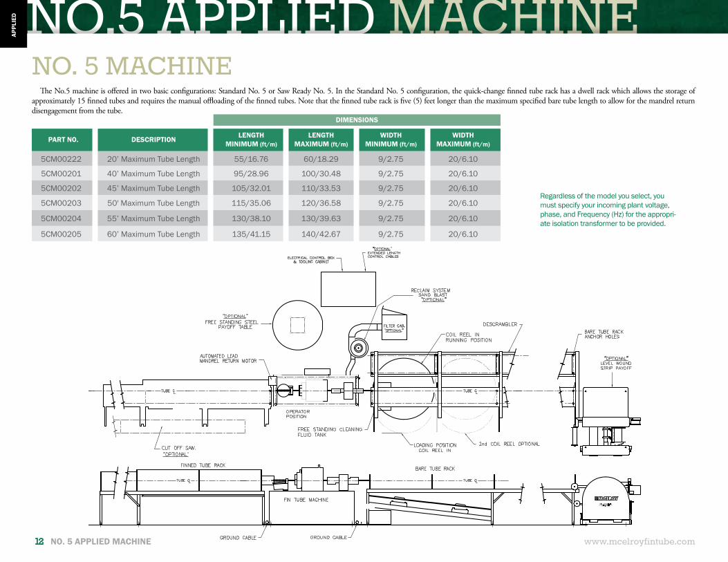
The No.5 machine is offered in two basic configurations: Standard No. 5 or Saw Ready No. 5. In the Standard No. 5 configuration, the quick-change finned tube rack has a dwell rack which allows the storage of approximately 15 finned tubes and requires the manual offloading of the finned tubes. Note that the finned tube rack is five (5) feet longer than the maximum specified bare tube length to allow for the mandrel return disengagement from the tube.
Regardless of the model you select, you must specify your incoming plant voltage, phase, and Frequency (Hz) for the appropri-ate isolation transformer to be provided.
PART NO. DESCRIPTION LENGTHMINIMUM (ft/m)
LENGTHMAXIMUM (ft/m)
WIDTHMINIMUM (ft/m)
WIDTHMAXIMUM (ft/m)
5CM00222 20’ Maximum Tube Length 55/16.76 60/18.29 9/2.75 20/6.10
5CM00201 40’ Maximum Tube Length 95/28.96 100/30.48 9/2.75 20/6.10
5CM00202 45’ Maximum Tube Length 105/32.01 110/33.53 9/2.75 20/6.10
5CM00203 50' Maximum Tube Length 115/35.06 120/36.58 9/2.75 20/6.10
5CM00204 55’ Maximum Tube Length 130/38.10 130/39.63 9/2.75 20/6.10
5CM00205 60’ Maximum Tube Length 135/41.15 140/42.67 9/2.75 20/6.10
www.mcelroyfintube.com12 NO. 5 APPLIED MACHINE
APPL
IED
DIMENSIONS
NO.5 APPLIED MACHINE
PART NO. DESCRIPTION LENGTHMINIMUM (ft/m)
LENGTHMAXIMUM (ft/m)
WIDTHMINIMUM (ft/m)
WIDTHMAXIMUM (ft/m)
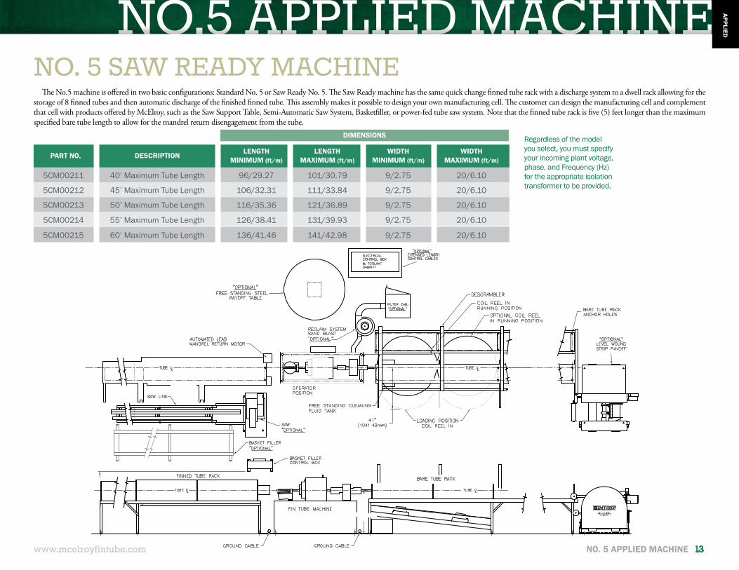
5CM00211 40’ Maximum Tube Length 96/29.27 101/30.79 9/2.75 20/6.10
5CM00212 45’ Maximum Tube Length 106/32.31 111/33.84 9/2.75 20/6.10
5CM00213 50’ Maximum Tube Length 116/35.36 121/36.89 9/2.75 20/6.10
5CM00214 55’ Maximum Tube Length 126/38.41 131/39.93 9/2.75 20/6.10
5CM00215 60’ Maximum Tube Length 136/41.46 141/42.98 9/2.75 20/6.10
NO. 5 SAW READY MACHINEThe No.5 machine is offered in two basic configurations: Standard No. 5 or Saw Ready No. 5. The Saw Ready machine has the same quick change finned tube rack with a discharge system to a dwell rack allowing for the
storage of 8 finned tubes and then automatic discharge of the finished finned tube. This assembly makes it possible to design your own manufacturing cell. The customer can design the manufacturing cell and complement that cell with products offered by McElroy, such as the Saw Support Table, Semi-Automatic Saw System, Basketfiller, or power-fed tube saw system. Note that the finned tube rack is five (5) feet longer than the maximum specified bare tube length to allow for the mandrel return disengagement from the tube.
Regardless of the model you select, you must specify your incoming plant voltage, phase, and Frequency (Hz) for the appropriate isolation transformer to be provided.
www.mcelroyfintube.com NO. 5 APPLIED MACHINE 13
APPLIED
DIMENSIONS
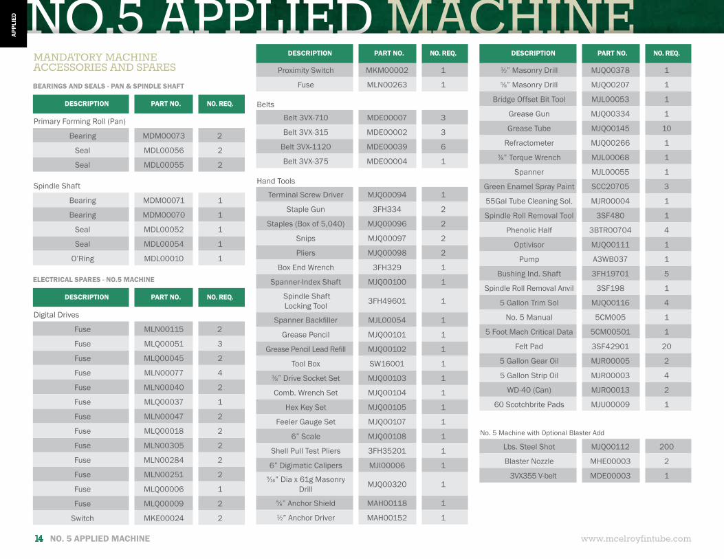
NO.5 APPLIED MACHINEDESCRIPTION PART NO. NO. REQ.
Primary Forming Roll (Pan)
Bearing MDM00073 2
Seal MDL00056 2
Seal MDL00055 2
Spindle Shaft
Bearing MDM00071 1
Bearing MDM00070 1
Seal MDL00052 1
Seal MDL00054 1
O’Ring MDL00010 1
DESCRIPTION PART NO. NO. REQ.
Digital Drives
Fuse MLN00115 2
Fuse MLQ00051 3
Fuse MLQ00045 2
Fuse MLN00077 4
Fuse MLN00040 2
Fuse MLQ00037 1
Fuse MLN00047 2
Fuse MLQ00018 2
Fuse MLN00305 2
Fuse MLN00284 2
Fuse MLN00251 2
Fuse MLQ00006 1
Fuse MLQ00009 2
Switch MKE00024 2
MANDATORY MACHINE ACCESSORIES AND SPARES
BEARINGS AND SEALS - PAN & SPINDLE SHAFT
ELECTRICAL SPARES - NO.5 MACHINE
Proximity Switch MKM00002 1
Fuse MLN00263 1
Belts
Belt 3VX-710 MDE00007 3
Belt 3VX-315 MDE00002 3
Belt 3VX-1120 MDE00039 6
Belt 3VX-375 MDE00004 1
Hand Tools
Terminal Screw Driver MJQ00094 1
Staple Gun 3FH334 2
Staples (Box of 5,040) MJQ00096 2
Snips MJQ00097 2
Pliers MJQ00098 2
Box End Wrench 3FH329 1
Spanner-Index Shaft MJQ00100 1
Spindle Shaft Locking Tool 3FH49601 1
Spanner Backfiller MJL00054 1
Grease Pencil MJQ00101 1
Grease Pencil Lead Refill MJQ00102 1
Tool Box SW16001 13⁄8” Drive Socket Set MJQ00103 1
Comb. Wrench Set MJQ00104 1
Hex Key Set MJQ00105 1
Feeler Gauge Set MJQ00107 1
6” Scale MJQ00108 1
Shell Pull Test Pliers 3FH35201 1
6” Digimatic Calipers MJI00006 15⁄16” Dia x 61g Masonry
Drill MJQ00320 1
5⁄8” Anchor Shield MAH00118 11⁄2” Anchor Driver MAH00152 1
1⁄2” Masonry Drill MJQ00378 15⁄8” Masonry Drill MJQ00207 1
Bridge Offset Bit Tool MJL00053 1
Grease Gun MJQ00334 1
Grease Tube MJQ00145 10
Refractometer MJQ00266 13⁄8” Torque Wrench MJL00068 1
Spanner MJL00055 1
Green Enamel Spray Paint SCC20705 3
55Gal Tube Cleaning Sol. MJR00004 1
Spindle Roll Removal Tool 3SF480 1
Phenolic Half 3BTR00704 4
Optivisor MJQ00111 1
Pump A3WB037 1
Bushing Ind. Shaft 3FH19701 5
Spindle Roll Removal Anvil 3SF198 1
5 Gallon Trim Sol MJQ00116 4
No. 5 Manual 5CM005 1
5 Foot Mach Critical Data 5CM00501 1
Felt Pad 3SF42901 20
5 Gallon Gear Oil MJR00005 2
5 Gallon Strip Oil MJR00003 4
WD-40 (Can) MJR00013 2
60 Scotchbrite Pads MJU00009 1
No. 5 Machine with Optional Blaster Add
Lbs. Steel Shot MJQ00112 200
Blaster Nozzle MHE00003 2
3VX355 V-belt MDE00003 1
DESCRIPTION PART NO. NO. REQ. DESCRIPTION PART NO. NO. REQ.
www.mcelroyfintube.com14 NO. 5 APPLIED MACHINE
APPL
IED
NO.5 APPLIED MACHINE
10.
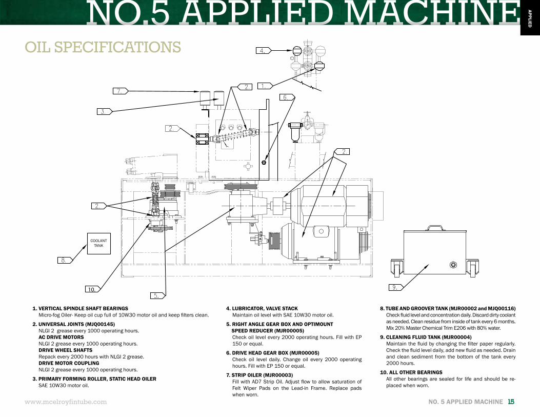
OIL SPECIFICATIONS
1. VERTICAL SPINDLE SHAFT BEARINGSMicro-fog Oiler- Keep oil cup full of 10W30 motor oil and keep filters clean.
2. UNIVERSAL JOINTS (MJQ00145)NLGI 2 grease every 1000 operating hours.AC DRIVE MOTORSNLGI 2 grease every 1000 operating hours.DRIVE WHEEL SHAFTSRepack every 2000 hours with NLGI 2 grease.DRIVE MOTOR COUPLINGNLGI 2 grease every 1000 operating hours.
3. PRIMARY FORMING ROLLER, STATIC HEAD OILERSAE 10W30 motor oil.
COOLANTTANK
4. LUBRICATOR, VALVE STACKMaintain oil level with SAE 10W30 motor oil.
5. RIGHT ANGLE GEAR BOX AND OPTIMOUNT SPEED REDUCER (MJR00005)
Check oil level every 2000 operating hours. Fill with EP 150 or equal.
6. DRIVE HEAD GEAR BOX (MJR00005)Check oil level daily. Change oil every 2000 operating hours. Fill with EP 150 or equal.
7. STRIP OILER (MJR00003)Fill with AD7 Strip Oil. Adjust flow to allow saturation of Felt Wiper Pads on the Lead-in Frame. Replace pads when worn.
8. TUBE AND GROOVER TANK (MJR00002 and MJQ00116)Check fluid level and concentration daily. Discard dirty coolant as needed. Clean residue from inside of tank every 6 months. Mix 20% Master Chemical Trim E206 with 80% water.
9. CLEANING FLUID TANK (MJR00004)Maintain the fluid by changing the filter paper regularly. Check the fluid level daily, add new fluid as needed. Drain and clean sediment from the bottom of the tank every 2000 hours.
10. ALL OTHER BEARINGSAll other bearings are sealed for life and should be re-placed when worn.
www.mcelroyfintube.com NO. 5 APPLIED MACHINE 15
APPLIED
NO.5 APPLIED MACHINE
www.mcelroyfintube.com16 NO. 5 APPLIED MACHINE
APPL
IED
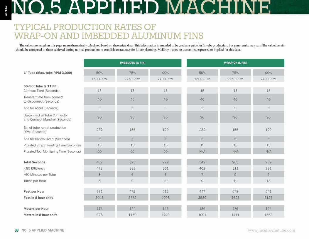
IMBEDDED (G-FIN) WRAP-ON (L-FIN)
1” Tube (Max. tube RPM 3,000) 50% 75% 90% 50% 75% 90%
1500 RPM 2250 RPM 2700 RPM 1500 RPM 2250 RPM 2700 RPM
50-foot Tube @ 11 FPIConnect Time (Seconds) 15 15 15 15 15 15
Transfer time from connect to disconnect (Seconds) 40 40 40 40 40 40
Add for Accel (Seconds) 5 5 5 5 5 5
Disconnect of Tube Connector and Connect Mandrel (Seconds) 30 30 30 30 30 30
Bal of tube run at production RPM (Seconds) 232 155 129 232 155 129
Add for Control Accel (Seconds) 5 5 5 5 5 5
Prorated Strip Threading Time (Seconds) 15 15 15 15 15 15
Prorated Tool Monitoring Time (Seconds) 60 60 60 N/A N/A N/A
Total Seconds 402 325 299 342 265 239
/.85 Efficiency 473 382 351 402 311 281
/60 Minutes per Tube 8 6 6 7 5 5
Tubes per Hour 8 9 10 9 12 13
Feet per Hour 381 472 512 447 578 641
Feet in 8 hour shift 3045 3772 4098 3580 4628 5128
Meters per Hour 116 144 156 136 176 195
Meters in 8 hour shift 928 1150 1249 1091 1411 1563
TYPICAL PRODUCTION RATES OFWRAP-ON AND IMBEDDED ALUMINUM FINS
The values presented on this page are mathematically calculated based on theoretical data. This information is intended to be used as a guide for fintube production, but your results may vary. The values herein should be compared to those achieved during normal production to establish an accuracy for future planning. McElroy makes no warranties, expressed or implied for this data.
NO.5 APPLIED MACHINE
www.mcelroyfintube.com NO. 5 APPLIED MACHINE 17
APPLIED
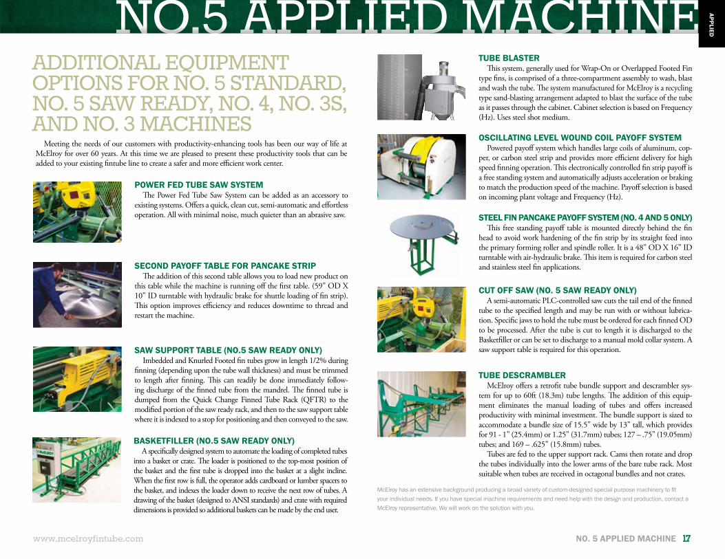
ADDITIONAL EQUIPMENT OPTIONS FOR NO. 5 STANDARD, NO. 5 SAW READY, NO. 4, NO. 3S, AND NO. 3 MACHINES
TUBE BLASTER This system, generally used for Wrap-On or Overlapped Footed Fin
type fins, is comprised of a three-compartment assembly to wash, blast and wash the tube. The system manufactured for McElroy is a recycling type sand-blasting arrangement adapted to blast the surface of the tube as it passes through the cabinet. Cabinet selection is based on Frequency (Hz). Uses steel shot medium.
OSCILLATING LEVEL WOUND COIL PAYOFF SYSTEMPowered payoff system which handles large coils of aluminum, cop-
per, or carbon steel strip and provides more efficient delivery for high speed finning operation. This electronically controlled fin strip payoff is a free standing system and automatically adjusts acceleration or braking to match the production speed of the machine. Payoff selection is based on incoming plant voltage and Frequency (Hz).
SECOND PAYOFF TABLE FOR PANCAKE STRIPThe addition of this second table allows you to load new product on
this table while the machine is running off the first table. (59” OD X 10” ID turntable with hydraulic brake for shuttle loading of fin strip). This option improves efficiency and reduces downtime to thread and restart the machine.
STEEL FIN PANCAKE PAYOFF SYSTEM (NO. 4 AND 5 ONLY)This free standing payoff table is mounted directly behind the fin
head to avoid work hardening of the fin strip by its straight feed into the primary forming roller and spindle roller. It is a 48” OD X 16” ID turntable with air-hydraulic brake. This item is required for carbon steel and stainless steel fin applications.
TUBE DESCRAMBLERMcElroy offers a retrofit tube bundle support and descrambler sys-
tem for up to 60ft (18.3m) tube lengths. The addition of this equip-ment eliminates the manual loading of tubes and offers increased productivity with minimal investment. The bundle support is sized to accommodate a bundle size of 15.5” wide by 13” tall, which provides for 91 - 1” (25.4mm) or 1.25” (31.7mm) tubes; 127 – .75” (19.05mm) tubes; and 169 – .625” (15.8mm) tubes.
Tubes are fed to the upper support rack. Cams then rotate and drop the tubes individually into the lower arms of the bare tube rack. Most suitable when tubes are received in octagonal bundles and not crates.
POWER FED TUBE SAW SYSTEMThe Power Fed Tube Saw System can be added as an accessory to
existing systems. Offers a quick, clean cut, semi-automatic and effortless operation. All with minimal noise, much quieter than an abrasive saw.
Meeting the needs of our customers with productivity-enhancing tools has been our way of life at McElroy for over 60 years. At this time we are pleased to present these productivity tools that can be added to your existing fintube line to create a safer and more efficient work center.
SAW SUPPORT TABLE (NO.5 SAW READY ONLY)Imbedded and Knurled Footed fin tubes grow in length 1/2% during
finning (depending upon the tube wall thickness) and must be trimmed to length after finning. This can readily be done immediately follow-ing discharge of the finned tube from the mandrel. The finned tube is dumped from the Quick Change Finned Tube Rack (QFTR) to the modified portion of the saw ready rack, and then to the saw support table where it is indexed to a stop for positioning and then conveyed to the saw.
CUT OFF SAW (NO. 5 SAW READY ONLY)A semi-automatic PLC-controlled saw cuts the tail end of the finned
tube to the specified length and may be run with or without lubrica-tion. Specific jaws to hold the tube must be ordered for each finned OD to be processed. After the tube is cut to length it is discharged to the Basketfiller or can be set to discharge to a manual mold collar system. A saw support table is required for this operation.
BASKETFILLER (NO.5 SAW READY ONLY)A specifically designed system to automate the loading of completed tubes
into a basket or crate. The loader is positioned to the top-most position of the basket and the first tube is dropped into the basket at a slight incline. When the first row is full, the operator adds cardboard or lumber spacers to the basket, and indexes the loader down to receive the next row of tubes. A drawing of the basket (designed to ANSI standards) and crate with required dimensions is provided so additional baskets can be made by the end user.
McElroy has an extensive background producing a broad variety of custom-designed special purpose machinery to fit your individual needs. If you have special machine requirements and need help with the design and production, contact a McElroy representative. We will work on the solution with you.

END-USERRESPONSIBILITIES
The customer is responsible for proper floor preparation, providing of electrical and air supply and the actual connection of the equipment to incoming plant voltage. Upon arrival, McElroy technicians will complete connections between power base and electrical cabinet, make air connections, level and align machine, demonstrate machine’s capabilities, and train operators.
• Air requirement: End user must provide a compressor capable of 30 CFM at 100 PSI. Compressor must be equipped with a dryer. End user must run a .75” ID line to the machine, fitted with a shop air fitting or quick disconnect.
• Power Consumption: End user must provide a 100 Amp service connection. McElroy provides the transformer to step up or down to the incoming plant voltage. Customer needs to specify incoming plant voltage and frequency (Hz) at the time the order is placed. The proper method of electrical connection is described in the manual and must be completed by a licensed electrician.
• Floor Preparation: The machine needs to be laid out off of a centerline (chalk line). Make the layout and drill holes off this centerline for the machine and racks. It is recommended that a drill guide be used to ensure that the holes are straight. It is also necessary to level and align the machine by using a bubble level and laser. Anchor bolts, shields, anchor shield drivers, masonry drills as well as the laser are shipped with the machine. Specific setting plan dimensions based on maximum tube length are provided at the time of order.
• For setup and run-in of the machine, the end user will provide tubes and fin strip of a recognized alloy, as specified in the “Critical Data” section of the machine manual.
• One full time operator and a part-time helper are required to run the machine and provide a continuous supply of tube and strip for the most efficient production.
• It is recommended that a team consisting of operations, maintenance, engineering and supervisory management be selected for training.
• End user will provide an Ethernet connection at the electrical control cabinet so the reporting management system can then connect directly to a local server. The machine may be connected using a CAT 5E cable up to a distance of 1148 feet (350 meters) from the computer reporting station.
PRIOR TO INSTALLATION
INITIAL OPERATIONS
HOW WE SHIPFor international shipment: machine and components are
skidded for ease of offloading. Machines with a maximum input length of 40 feet (12.2 meters) will generally ship in one forty foot high-cube container. Estimated weight, depending upon tooling requested, 13,000 pounds (5896 Kg). Machines with maximum input length of greater than 40 feet (12.2 meters) will require two containers. Weight and packing list is provided at the time the container is released to the trucking firm for transport to the port. A typical 50/55 foot machine with saw ready option, basket filler and oscillating level wound payoff will pack in two containers with these estimated weights: Container 1: 13,772 lbs (6247 Kg); and Container 2: 14,515 lbs. (6,584 Kg.)
Domestic shipments are usually made on 45 foot floats and may require up to three trucks, depending upon tooling and options ordered. Ask your customer service assistant for specifications at the time your order is placed. It is recommended that the truck be tarped or enclosed to protect the equipment during transit.
www.mcelroyfintube.com18 NO. 5 APPLIED MACHINE
APPL
IED
NO.5 APPLIED MACHINE
www.mcelroyfintube.com NO. 5 APPLIED MACHINE 19
APPLIED
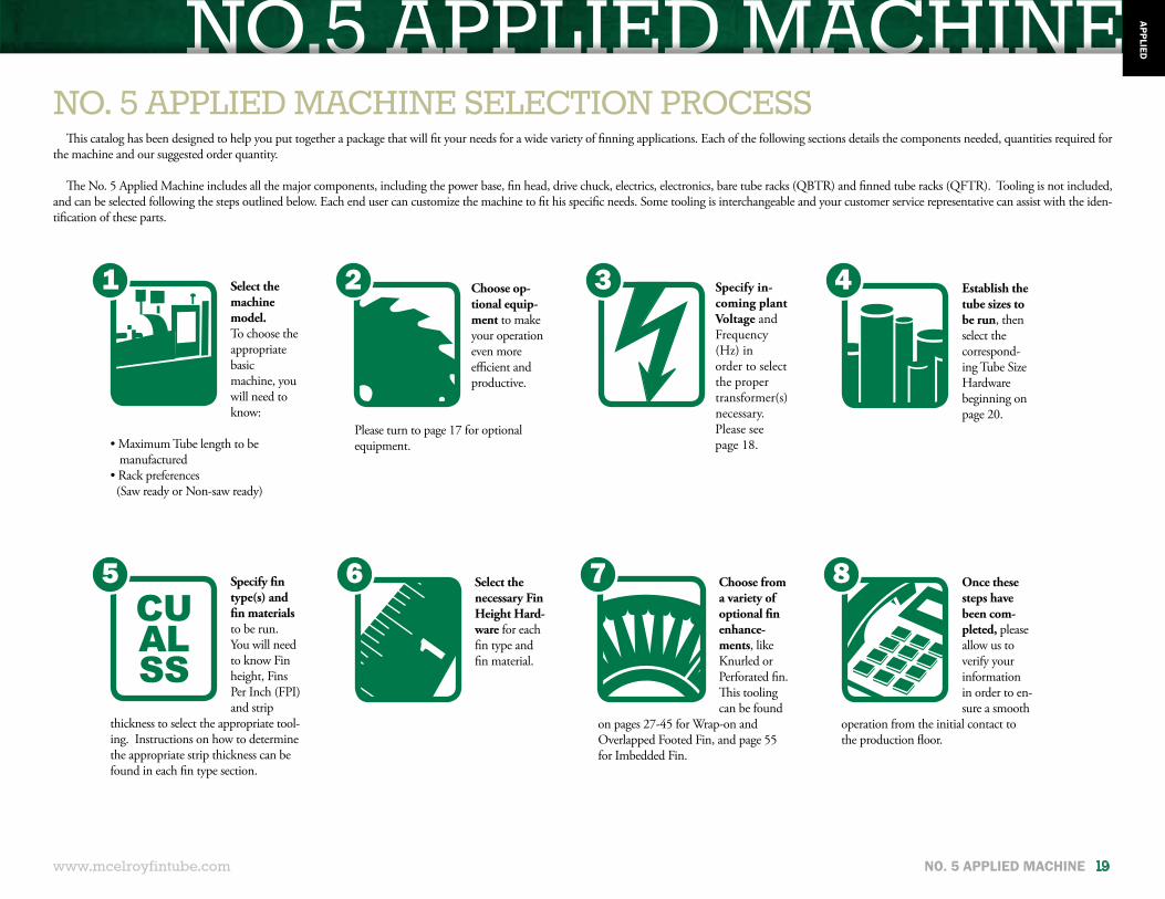
Once these steps have been com-pleted, please allow us to verify your information in order to en-sure a smooth
operation from the initial contact to the production floor.
Choose from a variety of optional fin enhance-ments, like Knurled or Perforated fin. This tooling can be found
on pages 27-45 for Wrap-on and Overlapped Footed Fin, and page 55 for Imbedded Fin.
Establish the tube sizes to be run, then select the correspond-ing Tube Size Hardware beginning on page 20.
NO. 5 APPLIED MACHINE SELECTION PROCESSThis catalog has been designed to help you put together a package that will fit your needs for a wide variety of finning applications. Each of the following sections details the components needed, quantities required for
the machine and our suggested order quantity.
The No. 5 Applied Machine includes all the major components, including the power base, fin head, drive chuck, electrics, electronics, bare tube racks (QBTR) and finned tube racks (QFTR). Tooling is not included, and can be selected following the steps outlined below. Each end user can customize the machine to fit his specific needs. Some tooling is interchangeable and your customer service representative can assist with the iden-tification of these parts.
Choose op-tional equip-ment to make your operation even more efficient and productive.
Please turn to page 17 for optional equipment.
Select the necessary Fin Height Hard-ware for each fin type and fin material.1
Select the machine model.To choose the appropriate basicmachine, you will need to know:
• Maximum Tube length to be manufactured• Rack preferences (Saw ready or Non-saw ready)
Specify fin type(s) and fin materials to be run. You will need to know Fin height, Fins Per Inch (FPI) and strip
thickness to select the appropriate tool-ing. Instructions on how to determine the appropriate strip thickness can be found in each fin type section.
Specify in-coming plant Voltage and Frequency (Hz) in order to select the proper transformer(s) necessary. Please see page 18.
1
5 6 7 8
2 3 4
TUBE SIZE HARDWARE
20 TUBE SIZE HARDWARE www.mcelroyfintube.com
TUB
EH
ARD
WAR
E
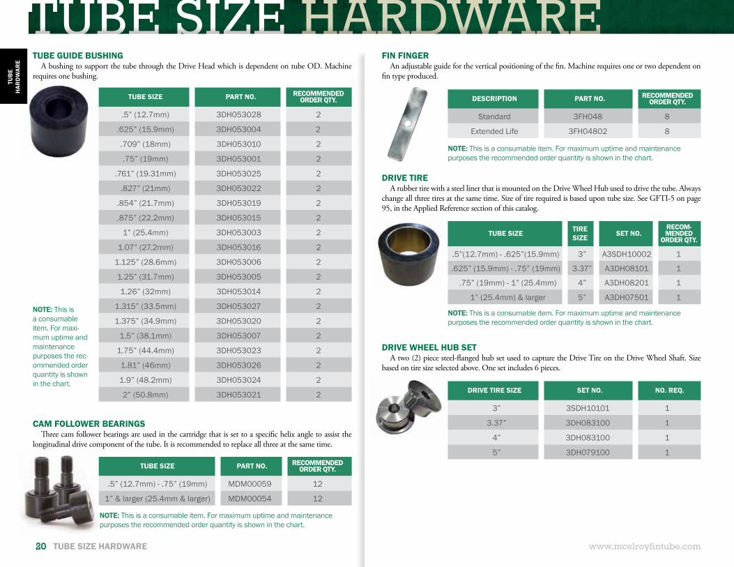
TUBE SIZE PART NO. RECOMMENDED ORDER QTY.
.5” (12.7mm) 3DH053028 2
.625” (15.9mm) 3DH053004 2
.709” (18mm) 3DH053010 2
.75” (19mm) 3DH053001 2
.761” (19.31mm) 3DH053025 2
.827” (21mm) 3DH053022 2
.854” (21.7mm) 3DH053019 2
.875” (22.2mm) 3DH053015 2
1” (25.4mm) 3DH053003 2
1.07” (27.2mm) 3DH053016 2
1.125” (28.6mm) 3DH053006 2
1.25” (31.7mm) 3DH053005 2
1.26” (32mm) 3DH053014 2
1.315” (33.5mm) 3DH053027 2
1.375” (34.9mm) 3DH053020 2
1.5” (38.1mm) 3DH053007 2
1.75” (44.4mm) 3DH053023 2
1.81” (46mm) 3DH053026 2
1.9” (48.2mm) 3DH053024 2
2” (50.8mm) 3DH053021 2
TUBE SIZE PART NO. RECOMMENDED ORDER QTY.
.5” (12.7mm) - .75” (19mm) MDM00059 12
1” & larger (25.4mm & larger) MDM00054 12
DESCRIPTION PART NO. RECOMMENDED ORDER QTY.
Standard 3FH048 8
Extended Life 3FH04802 8
TUBE SIZE TIRE SIZE SET NO.
RECOM-MENDED
ORDER QTY.
.5”(12.7mm) - .625”(15.9mm) 3” A3SDH10002 1
.625” (15.9mm) - .75” (19mm) 3.37” A3DH08101 1
.75” (19mm) - 1” (25.4mm) 4” A3DH08201 1
1” (25.4mm) & larger 5” A3DH07501 1
DRIVE TIRE SIZE SET NO. NO. REQ.
3” 3SDH10101 1
3.37” 3DH083100 1
4” 3DH083100 1
5” 3DH079100 1
NOTE: This is a consumable item. For maxi-mum uptime and maintenance purposes the rec-ommended order quantity is shown in the chart.
NOTE: This is a consumable item. For maximum uptime and maintenance purposes the recommended order quantity is shown in the chart.
NOTE: This is a consumable item. For maximum uptime and maintenance purposes the recommended order quantity is shown in the chart.
FIN FINGERAn adjustable guide for the vertical positioning of the fin. Machine requires one or two dependent on
fin type produced.
TUBE GUIDE BUSHINGA bushing to support the tube through the Drive Head which is dependent on tube OD. Machine
requires one bushing.
CAM FOLLOWER BEARINGS Three cam follower bearings are used in the cartridge that is set to a specific helix angle to assist the
longitudinal drive component of the tube. It is recommended to replace all three at the same time.
DRIVE TIREA rubber tire with a steel liner that is mounted on the Drive Wheel Hub used to drive the tube. Always
change all three tires at the same time. Size of tire required is based upon tube size. See GFTI-5 on page 95, in the Applied Reference section of this catalog.
DRIVE WHEEL HUB SETA two (2) piece steel-flanged hub set used to capture the Drive Tire on the Drive Wheel Shaft. Size
based on tire size selected above. One set includes 6 pieces.
NOTE: This is a consumable item. For maximum uptime and maintenance purposes the recommended order quantity is shown in the chart.
TUBE SIZE HARDWARE
TUBE SIZE HARDWARE 21www.mcelroyfintube.com
TUB
EH
ARD
WAR
E
TUBE SIZE PART NO. RECOMMENDED ORDER QTY.
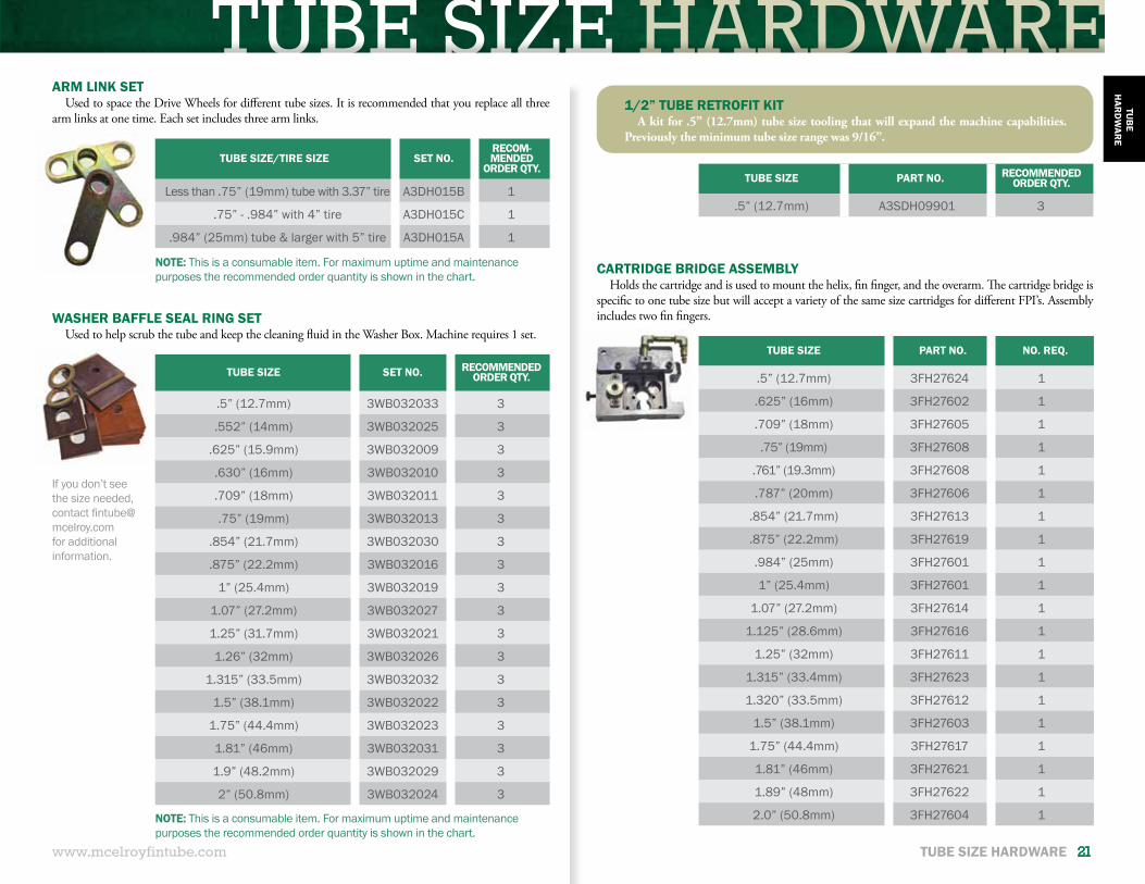
.5” (12.7mm) A3SDH09901 3
TUBE SIZE PART NO. NO. REQ.
.5” (12.7mm) 3FH27624 1
.625” (16mm) 3FH27602 1
.709” (18mm) 3FH27605 1
.75” (19mm) 3FH27608 1
.761” (19.3mm) 3FH27608 1
.787” (20mm) 3FH27606 1
.854” (21.7mm) 3FH27613 1
.875” (22.2mm) 3FH27619 1
.984” (25mm) 3FH27601 1
1” (25.4mm) 3FH27601 1
1.07” (27.2mm) 3FH27614 1
1.125” (28.6mm) 3FH27616 1
1.25” (32mm) 3FH27611 1
1.315” (33.4mm) 3FH27623 1
1.320” (33.5mm) 3FH27612 1
1.5” (38.1mm) 3FH27603 1
1.75” (44.4mm) 3FH27617 1
1.81” (46mm) 3FH27621 1
1.89” (48mm) 3FH27622 1
2.0” (50.8mm) 3FH27604 1
TUBE SIZE/TIRE SIZE SET NO.RECOM-MENDED
ORDER QTY.
Less than .75” (19mm) tube with 3.37” tire A3DH015B 1
.75” - .984” with 4” tire A3DH015C 1
.984” (25mm) tube & larger with 5” tire A3DH015A 1
TUBE SIZE SET NO. RECOMMENDED ORDER QTY.
.5” (12.7mm) 3WB032033 3
.552” (14mm) 3WB032025 3
.625” (15.9mm) 3WB032009 3
.630” (16mm) 3WB032010 3
.709” (18mm) 3WB032011 3
.75” (19mm) 3WB032013 3
.854” (21.7mm) 3WB032030 3
.875” (22.2mm) 3WB032016 3
1” (25.4mm) 3WB032019 3
1.07” (27.2mm) 3WB032027 3
1.25” (31.7mm) 3WB032021 3
1.26” (32mm) 3WB032026 3
1.315” (33.5mm) 3WB032032 3
1.5” (38.1mm) 3WB032022 3
1.75” (44.4mm) 3WB032023 3
1.81” (46mm) 3WB032031 3
1.9” (48.2mm) 3WB032029 3
2” (50.8mm) 3WB032024 3
If you don’t see the size needed, contact [email protected] for additional information.
NOTE: This is a consumable item. For maximum uptime and maintenance purposes the recommended order quantity is shown in the chart.
NOTE: This is a consumable item. For maximum uptime and maintenance purposes the recommended order quantity is shown in the chart.
1/2” TUBE RETROFIT KITA kit for .5” (12.7mm) tube size tooling that will expand the machine capabilities.
Previously the minimum tube size range was 9/16”.
ARM LINK SETUsed to space the Drive Wheels for different tube sizes. It is recommended that you replace all three
arm links at one time. Each set includes three arm links.
WASHER BAFFLE SEAL RING SETUsed to help scrub the tube and keep the cleaning fluid in the Washer Box. Machine requires 1 set.
CARTRIDGE BRIDGE ASSEMBLYHolds the cartridge and is used to mount the helix, fin finger, and the overarm. The cartridge bridge is
specific to one tube size but will accept a variety of the same size cartridges for different FPI’s. Assembly includes two fin fingers.
TUBE SIZE HARDWARE
22 TUBE SIZE HARDWARE www.mcelroyfintube.com
TUB
EH
ARD
WAR
E
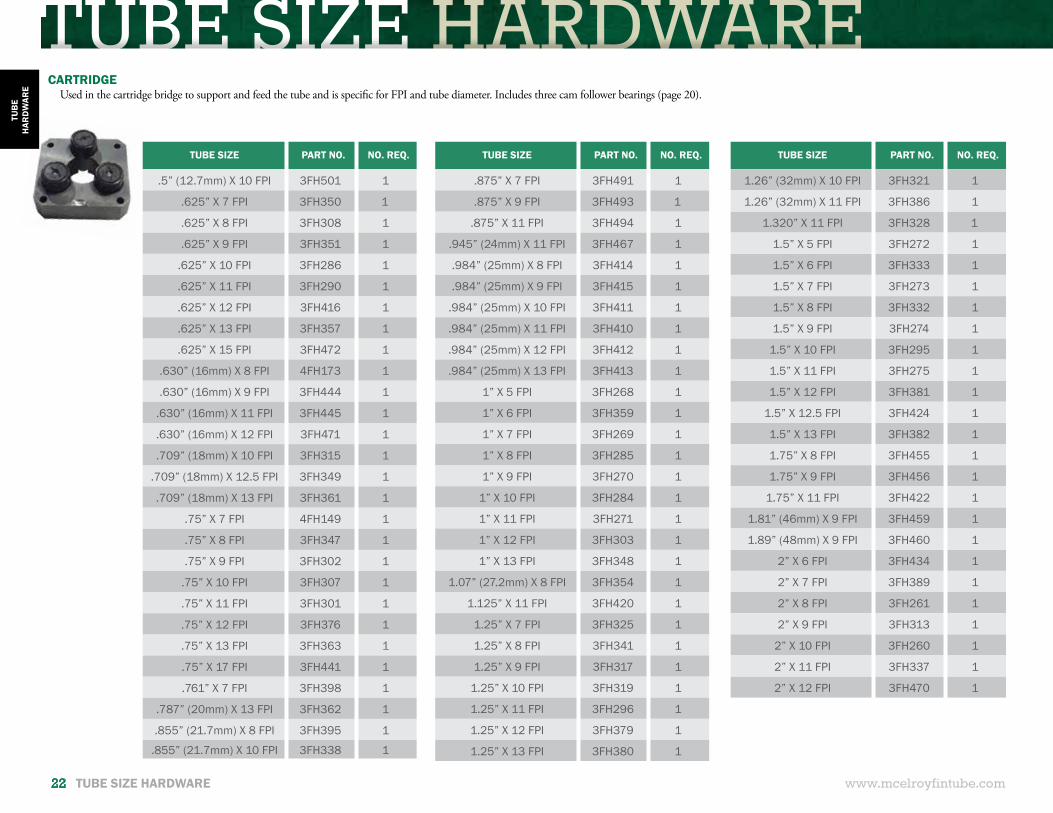
CARTRIDGEUsed in the cartridge bridge to support and feed the tube and is specific for FPI and tube diameter. Includes three cam follower bearings (page 20).
TUBE SIZE PART NO. NO. REQ.
.5” (12.7mm) X 10 FPI 3FH501 1
.625” X 7 FPI 3FH350 1
.625” X 8 FPI 3FH308 1
.625” X 9 FPI 3FH351 1
.625” X 10 FPI 3FH286 1
.625” X 11 FPI 3FH290 1
.625” X 12 FPI 3FH416 1
.625” X 13 FPI 3FH357 1
.625” X 15 FPI 3FH472 1
.630” (16mm) X 8 FPI 4FH173 1
.630” (16mm) X 9 FPI 3FH444 1
.630” (16mm) X 11 FPI 3FH445 1
.630” (16mm) X 12 FPI 3FH471 1
.709” (18mm) X 10 FPI 3FH315 1
.709” (18mm) X 12.5 FPI 3FH349 1
.709” (18mm) X 13 FPI 3FH361 1
.75” X 7 FPI 4FH149 1
.75” X 8 FPI 3FH347 1
.75” X 9 FPI 3FH302 1
.75” X 10 FPI 3FH307 1
.75” X 11 FPI 3FH301 1
.75” X 12 FPI 3FH376 1
.75” X 13 FPI 3FH363 1
.75” X 17 FPI 3FH441 1
.761” X 7 FPI 3FH398 1
.787” (20mm) X 13 FPI 3FH362 1
.855” (21.7mm) X 8 FPI 3FH395 1
.855” (21.7mm) X 10 FPI 3FH338 1
TUBE SIZE PART NO. NO. REQ.
1.26” (32mm) X 10 FPI 3FH321 1
1.26” (32mm) X 11 FPI 3FH386 1
1.320” X 11 FPI 3FH328 1
1.5” X 5 FPI 3FH272 1
1.5” X 6 FPI 3FH333 1
1.5” X 7 FPI 3FH273 1
1.5” X 8 FPI 3FH332 1
1.5” X 9 FPI 3FH274 1
1.5” X 10 FPI 3FH295 1
1.5” X 11 FPI 3FH275 1
1.5” X 12 FPI 3FH381 1
1.5” X 12.5 FPI 3FH424 1
1.5” X 13 FPI 3FH382 1
1.75” X 8 FPI 3FH455 1
1.75” X 9 FPI 3FH456 1
1.75” X 11 FPI 3FH422 1
1.81” (46mm) X 9 FPI 3FH459 1
1.89” (48mm) X 9 FPI 3FH460 1
2” X 6 FPI 3FH434 1
2” X 7 FPI 3FH389 1
2” X 8 FPI 3FH261 1
2” X 9 FPI 3FH313 1
2” X 10 FPI 3FH260 1
2” X 11 FPI 3FH337 1
2” X 12 FPI 3FH470 1
TUBE SIZE PART NO. NO. REQ.
.875” X 7 FPI 3FH491 1
.875” X 9 FPI 3FH493 1
.875” X 11 FPI 3FH494 1
.945” (24mm) X 11 FPI 3FH467 1
.984” (25mm) X 8 FPI 3FH414 1
.984” (25mm) X 9 FPI 3FH415 1
.984” (25mm) X 10 FPI 3FH411 1
.984” (25mm) X 11 FPI 3FH410 1
.984” (25mm) X 12 FPI 3FH412 1
.984” (25mm) X 13 FPI 3FH413 1
1” X 5 FPI 3FH268 1
1” X 6 FPI 3FH359 1
1” X 7 FPI 3FH269 1
1” X 8 FPI 3FH285 1
1” X 9 FPI 3FH270 1
1” X 10 FPI 3FH284 1
1” X 11 FPI 3FH271 1
1” X 12 FPI 3FH303 1
1” X 13 FPI 3FH348 1
1.07” (27.2mm) X 8 FPI 3FH354 1
1.125” X 11 FPI 3FH420 1
1.25” X 7 FPI 3FH325 1
1.25” X 8 FPI 3FH341 1
1.25” X 9 FPI 3FH317 1
1.25” X 10 FPI 3FH319 1
1.25” X 11 FPI 3FH296 1
1.25” X 12 FPI 3FH379 1
1.25” X 13 FPI 3FH380 1
TUBE SIZE HARDWARE
TUBE SIZE HARDWARE 23www.mcelroyfintube.com
TUB
EH
ARD
WAR
E
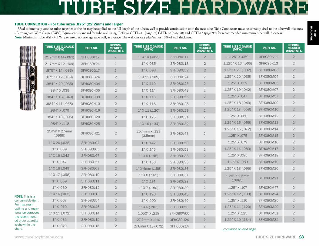
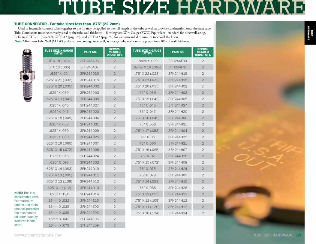
TUBE CONNECTOR - For tube sizes .875” (22.2mm) and largerUsed to internally connect tubes together so the fin may be applied to the full length of the tube as well as provide continuation onto the next tube. Tube Connectors must be correctly sized to the tube wall thickness
- Birmingham Wire Gauge (BWG) Equivalent - standard for tube wall sizing. Refer to GFTI –11 (page 97) GFTI-12 (page 98) and GFTI-13 (page 99) for recommended minimum tube wall thickness.Note: Minimum Tube Wall (MTW) preferred, not average tube wall, as average tube wall can vary plus/minus 10% of wall thickness.
TUBE SIZE X GAUGE (MTW) PART NO.
RECOM-MENDED
ORDER QTY.
21.7mm X 14 (.083) 3FH080Y17 2
21.7mm X 12 (.109) 3FH080Y24 2
.875” X 14 (.083) 3FH080G17 2
.875” X 12 (.109) 3FH080G24 2
.984” X 20 (.035) 3FH080H04 2
.984” X .039 3FH080H05 2
.984” X 18 (.049) 3FH080H09 2
.984” X 17 (.058) 3FH080H10 2
.984” X .079 3FH080H16 2
.984” X 13 (.095) 3FH080H20 2
.984” X .118 3FH080H28 2
25mm X 2.5mm (.0985) 3FH080H21 2
1” X 20 (.035) 3FH080J04 2
1” X .039 3FH080J05 2
1” X 19 (.042) 3FH080J07 2
1” X .047 3FH080J57 2
1” X 18 (.049) 3FH080J09 2
1” X 17 (.058) 3FH080J10 2
1” X .059 3FH080J11 2
1” X .060 3FH080J12 2
1” X 16 (.065) 3FH080J13 2
1” X .067 3FH080J54 2
1” X .070 3FH080J46 2
1” X 15 (.072) 3FH080J14 2
1” X .075 3FH080J15 2
1” X .079 3FH080J16 2
TUBE SIZE X GAUGE (MTW) PART NO.
RECOM-MENDED
ORDER QTY.
1.125” X .059 3FH080K11 2
1.125” X 16 (.065) 3FH080K13 2
1.25” X 21 (.032) 3FH080M03 2
1.25” X 20 (.035) 3FH080M04 2
1.25” X .039 3FH080M05 2
1.25” X 19 (.042) 3FH080M07 2
1.25” X .047 3FH080M57 2
1.25” X 18 (.049) 3FH080M09 2
1.25” X 17 (.058) 3FH080M10 2
1.25” X .060 3FH080M12 2
1.25” X 16 (.065) 3FH080M13 2
1.25” X 15 (.072) 3FH080M14 2
1.25” X .075 3FH080M15 2
1.25” X .079 3FH080M16 2
1.25” X 14 (.083) 3FH080M17 2
1.25” X .085 3FH080M18 2
1.25” X .089 3FH080M19 2
1.25” X 13 (.095) 3FH080M20 2
1.25” X 2.5mm (.0985) 3FH080M21 2
1.25” X .107 3FH080M47 2
1.25” X 12 (.109) 3FH080M24 2
1.25” X .110 3FH080M25 2
1.25” X 11 (.120) 3FH080M29 2
1.25” X .125 3FH080M31 2
1.25” X 10 (.134) 3FH080M32 2
TUBE SIZE X GAUGE (MTW) PART NO.
RECOM-MENDED
ORDER QTY.
1” X 14 (.083) 3FH080J17 2
1” X .085 3FH080J18 2
1” X .093 3FH080J52 2
1” X 12 (.109) 3FH080J24 2
1” X .110 3FH080J25 2
1” X .114 3FH080J48 2
1” X .116 3FH080J55 2
1” X .118 3FH080J28 2
1” X 11 (.120) 3FH080J29 2
1” X .125 3FH080J31 2
1” X 10 (.134) 3FH080J32 2
25.4mm X .138 (3.5mm) 3FH080J43 2
1” X .142 3FH080J50 2
1” X .145 3FH080J53 2
1” X 9 (.148) 3FH080J33 2
1” X .156 3FH080J35 2
1” X 4mm (.158) 3FH080J36 2
1” X 8 (.165) 3FH080J37 2
1” X .174 3FH080J38 2
1” X 7 (.180) 3FH080J39 2
1” X .190 3FH080J45 2
1” X .200 3FH080J49 2
1” X 6 (.203) 3FH080J58 2
1.050” X .218 3FH080W60 2
27.2mm X .110 3FH080U24 2
27.8mm X 15 (.072) 3FH080Z14 2
NOTE: This is a consumable item. For maximum uptime and main-tenance purposes the recommend-ed order quantity is shown in the chart. ...continued on next page
TUBE SIZE HARDWARE
24 TUBE SIZE HARDWARE www.mcelroyfintube.com
TUB
EH
ARD
WAR
E
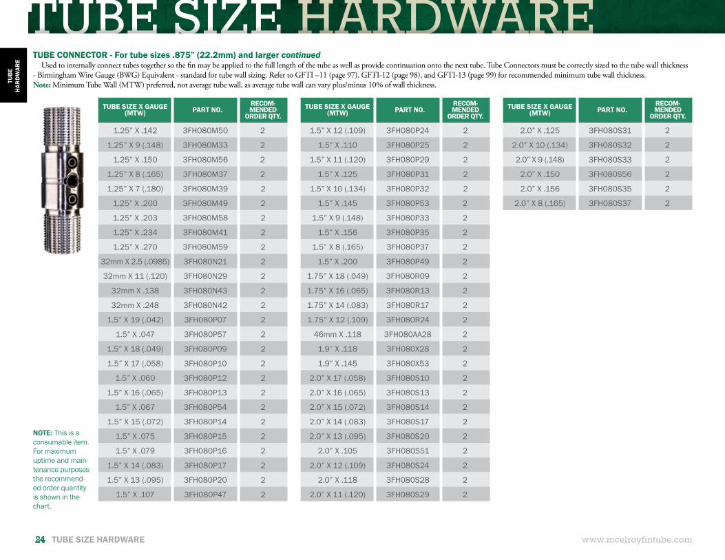
TUBE CONNECTOR - For tube sizes .875” (22.2mm) and larger continuedUsed to internally connect tubes together so the fin may be applied to the full length of the tube as well as provide continuation onto the next tube. Tube Connectors must be correctly sized to the tube wall thickness
- Birmingham Wire Gauge (BWG) Equivalent - standard for tube wall sizing. Refer to GFTI –11 (page 97), GFTI-12 (page 98), and GFTI-13 (page 99) for recommended minimum tube wall thickness.Note: Minimum Tube Wall (MTW) preferred, not average tube wall, as average tube wall can vary plus/minus 10% of wall thickness.
TUBE SIZE X GAUGE (MTW) PART NO.
RECOM-MENDED
ORDER QTY.
1.25” X .142 3FH080M50 2
1.25” X 9 (.148) 3FH080M33 2
1.25” X .150 3FH080M56 2
1.25” X 8 (.165) 3FH080M37 2
1.25” X 7 (.180) 3FH080M39 2
1.25” X .200 3FH080M49 2
1.25” X .203 3FH080M58 2
1.25” X .234 3FH080M41 2
1.25” X .270 3FH080M59 2
32mm X 2.5 (.0985) 3FH080N21 2
32mm X 11 (.120) 3FH080N29 2
32mm X .138 3FH080N43 2
32mm X .248 3FH080N42 2
1.5” X 19 (.042) 3FH080P07 2
1.5” X .047 3FH080P57 2
1.5” X 18 (.049) 3FH080P09 2
1.5” X 17 (.058) 3FH080P10 2
1.5” X .060 3FH080P12 2
1.5” X 16 (.065) 3FH080P13 2
1.5” X .067 3FH080P54 2
1.5” X 15 (.072) 3FH080P14 2
1.5” X .075 3FH080P15 2
1.5” X .079 3FH080P16 2
1.5” X 14 (.083) 3FH080P17 2
1.5” X 13 (.095) 3FH080P20 2
1.5” X .107 3FH080P47 2
TUBE SIZE X GAUGE (MTW) PART NO.
RECOM-MENDED
ORDER QTY.
2.0” X .125 3FH080S31 2
2.0” X 10 (.134) 3FH080S32 2
2.0” X 9 (.148) 3FH080S33 2
2.0” X .150 3FH080S56 2
2.0” X .156 3FH080S35 2
2.0” X 8 (.165) 3FH080S37 2
TUBE SIZE X GAUGE (MTW) PART NO.
RECOM-MENDED
ORDER QTY.
1.5” X 12 (.109) 3FH080P24 2
1.5” X .110 3FH080P25 2
1.5” X 11 (.120) 3FH080P29 2
1.5” X .125 3FH080P31 2
1.5” X 10 (.134) 3FH080P32 2
1.5” X .145 3FH080P53 2
1.5” X 9 (.148) 3FH080P33 2
1.5” X .156 3FH080P35 2
1.5” X 8 (.165) 3FH080P37 2
1.5” X .200 3FH080P49 2
1.75” X 18 (.049) 3FH080R09 2
1.75” X 16 (.065) 3FH080R13 2
1.75” X 14 (.083) 3FH080R17 2
1.75” X 12 (.109) 3FH080R24 2
46mm X .118 3FH080AA28 2
1.9” X .118 3FH080X28 2
1.9” X .145 3FH080X53 2
2.0” X 17 (.058) 3FH080S10 2
2.0” X 16 (.065) 3FH080S13 2
2.0” X 15 (.072) 3FH080S14 2
2.0” X 14 (.083) 3FH080S17 2
2.0” X 13 (.095) 3FH080S20 2
2.0” X .105 3FH080S51 2
2.0” X 12 (.109) 3FH080S24 2
2.0” X .118 3FH080S28 2
2.0” X 11 (.120) 3FH080S29 2
NOTE: This is a consumable item. For maximum uptime and main-tenance purposes the recommend-ed order quantity is shown in the chart.
TUBE SIZE HARDWARE
TUBE SIZE HARDWARE 25www.mcelroyfintube.com
TUB
EH
ARD
WAR
E
TUBE SIZE X GAUGE (MTW) PART NO.
RECOM-MENDED
ORDER QTY.
.5” X 18 (.049) 3FH245A06 2
.5” X 16 (.065) 3FH245A07 2
.625” X .02 3FH244D30 2
.625” X 21 (.032) 3FH244D15 2
.625” X 20 (.035) 3FH244D02 2
.625” X .039 3FH244D03 2
.625” X 19 (.042) 3FH244D05 2
.625” X .045 3FH244D27 2
.625” X .047 3FH244D20 2
.625” X 18 (.049) 3FH244D06 2
.625” X .053 3FH244D31 2
.625” X .059 3FH244D29 2
.625” X .060 3FH244D25 2
.625” X 16 (.065) 3FH244D07 2
.625” X 15 (.072) 3FH244D08 2
.625” X .075 3FH244D24 2
.625” X .076 3FH244D32 2
.625” X 14 (.083) 3FH244D10 2
.625” X 13 (.095) 3FH244D11 2
.625” X 12 (.109) 3FH244D12 2
.625” X 11 (.12) 3FH244D13 2
.625” X .134 3FH244D14 2
16mm X .032 3FH244E15 2
16mm X .035 3FH244E02 2
16mm X .039 3FH244E03 2
16mm X .042 3FH244E05 2
16mm X .079 3FH244E09 2
TUBE SIZE X GAUGE (MTW) PART NO.
RECOM-MENDED
ORDER QTY.
18mm X .039 3FH244F03 2
18mm X 16 (.065) 3FH244F07 2
.75” X 22 (.028) 3FH244H19 2
.75” X 21 (.032) 3FH244H15 2
.75” X 20 (.035) 3FH244H02 2
.75” X .039 3FH244H03 2
.75” X 19 (.042) 3FH244H05 2
.75” X .045 3FH244H27 2
.75” X .047 3FH244H20 2
.75” X 18 (.049) 3FH244H06 2
.75” X .053 3FH244H31 2
.75” X 17 (.058) 3FH244H04 2
.75” X .06 3FH244H25 2
.75” X .063 3FH244H21 2
.75” X 16 (.065) 3FH244H07 2
.75” X .07 3FH244H28 2
.75” X 15 (.072) 3FH244H08 2
.75” X .075 3FH244H24 2
.75” X .079 3FH244H09 2
.75” X 14 (.083) 3FH244H10 2
.75” X .085 3FH244H26 2
.75” X 13 (.095) 3FH244H11 2
.75” X 12 (.109) 3FH244H12 2
.75” X 11 (.120) 3FH244H13 2
.75” X 10 (.134) 3FH244H14 2
NOTE: This is a consumable item. For maximum uptime and main-tenance purposes the recommend-ed order quantity is shown in the chart.
TUBE CONNECTOR - For tube sizes less than .875” (22.2mm)Used to internally connect tubes together so the fin may be applied to the full length of the tube as well as provide continuation onto the next tube.
Tube Connectors must be correctly sized to the tube wall thickness - Birmingham Wire Gauge (BWG) Equivalent - standard for tube wall sizing. Refer to GFTI –11 (page 97), GFTI-12 (page 98), and GFTI-13 (page 99) for recommended minimum tube wall thickness.Note: Minimum Tube Wall (MTW) preferred, not average tube wall, as average tube wall can vary plus/minus 10% of wall thickness.
TUBE SIZE HARDWARE
26 TUBE SIZE HARDWARE www.mcelroyfintube.com
TUB
EH
ARD
WAR
E
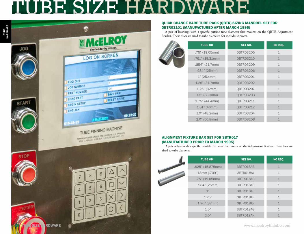
QUICK CHANGE BARE TUBE RACK (QBTR) SIZING MANDREL SET FOR QBTR03101 (MANUFACTURED AFTER MARCH 1995)
A pair of bushings with a specific outside tube diameter that mounts on the QBTR Adjustment Bracket. These discs are sized to tube diameter. Set includes 2 pieces.
TUBE OD SET NO. NO REQ.
.75” (19.05mm) QBTR03205 1
.761” (19.31mm) QBTR03210 1
.854” (21.7mm) QBTR03209 1
.984” (25mm) QBTR03206 1
1” (25.4mm) QBTR03201 1
1.25” (31.7mm) QBTR03202 1
1.26” (32mm) QBTR03207 1
1.5” (38.1mm) QBTR03203 1
1.75” (44.4mm) QBTR03211 1
1.81” (46mm) QBTR03212 1
1.9” (48.2mm) QBTR03204 1
2.0” (50.8mm) QBTR03208 1
TUBE OD SET NO. NO REQ.
.625” (15.875mm) 3BTR018AB 1
18mm (.709”) 3BTR018AJ 1
.75” (19.05mm) 3BTR018AC 1
.984” (25mm) 3BTR018AS 1
1” 3BTR018AE 1
1.25” 3BTR018AF 1
1.26” (32mm) 3BTR018AV 1
1.5” 3BTR018AG 1
2.0” 3BTR018AH 1
ALIGNMENT FIXTURE BAR SET FOR 3BTR017(MANUFACTURED PRIOR TO MARCH 1995)
A pair of bars with a specific outside diameter that mount on the Adjustment Bracket. These bars are sized to tube diameter.
FIN HEIGHT HARDWARE WRAP-ONWRAP-ON (L-FIN)
www.mcelroyfintube.com
WR
AP-ON
WRAP-ON FIN 27
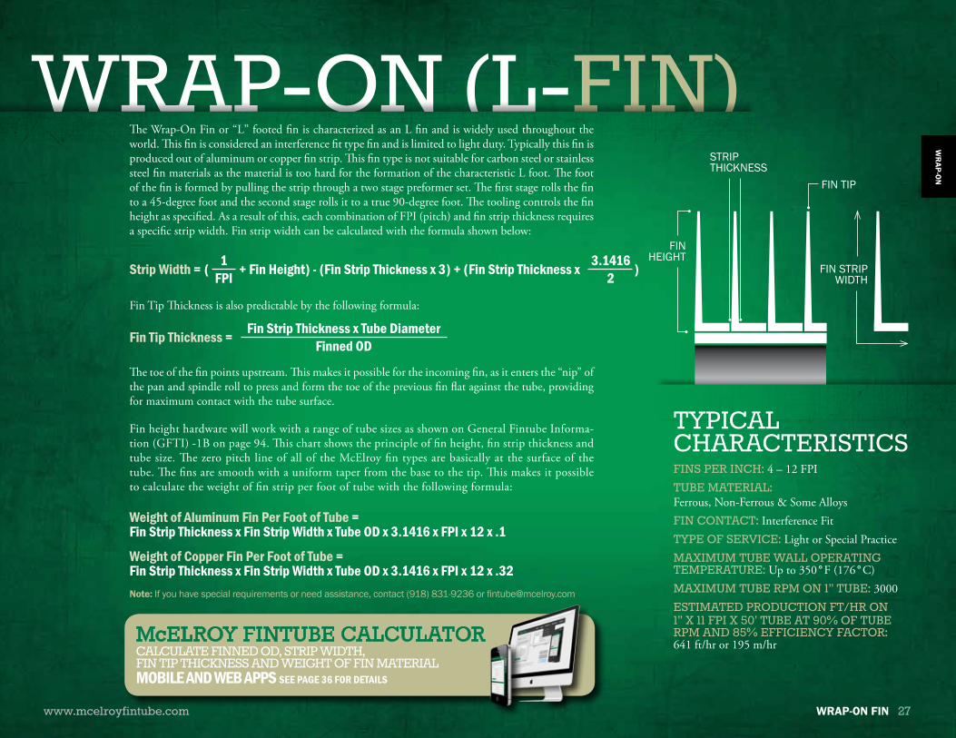
The Wrap-On Fin or “L” footed fin is characterized as an L fin and is widely used throughout the world. This fin is considered an interference fit type fin and is limited to light duty. Typically this fin is produced out of aluminum or copper fin strip. This fin type is not suitable for carbon steel or stainless steel fin materials as the material is too hard for the formation of the characteristic L foot. The foot of the fin is formed by pulling the strip through a two stage preformer set. The first stage rolls the fin to a 45-degree foot and the second stage rolls it to a true 90-degree foot. The tooling controls the fin height as specified. As a result of this, each combination of FPI (pitch) and fin strip thickness requires a specific strip width. Fin strip width can be calculated with the formula shown below:
The toe of the fin points upstream. This makes it possible for the incoming fin, as it enters the “nip” of the pan and spindle roll to press and form the toe of the previous fin flat against the tube, providing for maximum contact with the tube surface.
Fin height hardware will work with a range of tube sizes as shown on General Fintube Informa-tion (GFTI) -1B on page 94. This chart shows the principle of fin height, fin strip thickness and tube size. The zero pitch line of all of the McElroy fin types are basically at the surface of the tube. The fins are smooth with a uniform taper from the base to the tip. This makes it possible to calculate the weight of fin strip per foot of tube with the following formula:
Strip Width = ( + Fin Height) - (Fin Strip Thickness x 3) + (Fin Strip Thickness x )1FPI
3.14162
Weight of Aluminum Fin Per Foot of Tube = Fin Strip Thickness x Fin Strip Width x Tube OD x 3.1416 x FPI x 12 x .1
Weight of Copper Fin Per Foot of Tube = Fin Strip Thickness x Fin Strip Width x Tube OD x 3.1416 x FPI x 12 x .32
Fin Tip Thickness = Fin Strip Thickness x Tube DiameterFinned OD
Fin Tip Thickness is also predictable by the following formula:
FIN TIP
STRIP THICKNESS
FIN STRIP WIDTH
FIN HEIGHT
FINS PER INCH: 4 – 12 FPITUBE MATERIAL: Ferrous, Non-Ferrous & Some AlloysFIN CONTACT: Interference FitTYPE OF SERVICE: Light or Special PracticeMAXIMUM TUBE WALL OPERATING TEMPERATURE: Up to 350°F (176°C)MAXIMUM TUBE RPM ON 1” TUBE: 3000ESTIMATED PRODUCTION FT/HR ON1” X 11 FPI X 50’ TUBE AT 90% OF TUBE RPM AND 85% EFFICIENCY FACTOR:641 ft/hr or 195 m/hr
TYPICALCHARACTERISTICS
Note: If you have special requirements or need assistance, contact (918) 831-9236 or [email protected]
McELROY FINTUBE CALCULATOR CALCULATE FINNED OD, STRIP WIDTH,FIN TIP THICKNESS AND WEIGHT OF FIN MATERIALMOBILE AND WEB APPS SEE PAGE 36 FOR DETAILS
WRAP-ON FIN HEIGHT HARDWARE
Universal StripGuide Assembly
Roll to 90° Foot & 5/8"Controlled Height UsingPreform Roll No. 1 & 2
Roll to 45° Foot UsingPreform Roll No. 3 & 4
Strip .016" X .693"
Powered & SynchronizedWith Tube
Adjustable
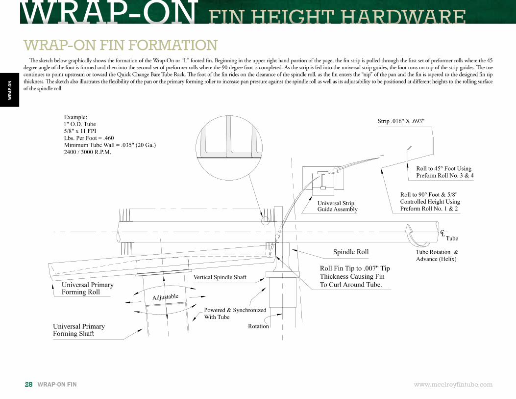
Example:1" O.D. Tube5/8" x 11 FPILbs. Per Foot = .460Minimum Tube Wall = .035" (20 Ga.)2400 / 3000 R.P.M.
Spindle Roll
Roll Fin Tip to .007" TipThickness Causing FinTo Curl Around Tube.
Vertical Spindle Shaft
Universal PrimaryForming Shaft
Universal PrimaryForming Roll
CLTube
Rotation
Tube Rotation &Advance (Helix)
www.mcelroyfintube.com
WR
AP-O
N
28 WRAP-ON FIN
WRAP-ON FIN FORMATIONThe sketch below graphically shows the formation of the Wrap-On or “L” footed fin. Beginning in the upper right hand portion of the page, the fin strip is pulled through the first set of preformer rolls where the 45
degree angle of the foot is formed and then into the second set of preformer rolls where the 90 degree foot is completed. As the strip is fed into the universal strip guides, the foot runs on top of the strip guides. The toe continues to point upstream or toward the Quick Change Bare Tube Rack. The foot of the fin rides on the clearance of the spindle roll, as the fin enters the “nip” of the pan and the fin is tapered to the designed fin tip thickness. The sketch also illustrates the flexibility of the pan or the primary forming roller to increase pan pressure against the spindle roll as well as its adjustability to be positioned at different heights to the rolling surface of the spindle roll.
FIN HEIGHT HARDWARE WRAP-ON
www.mcelroyfintube.com
WR
AP-ON
WRAP-ON FIN 29
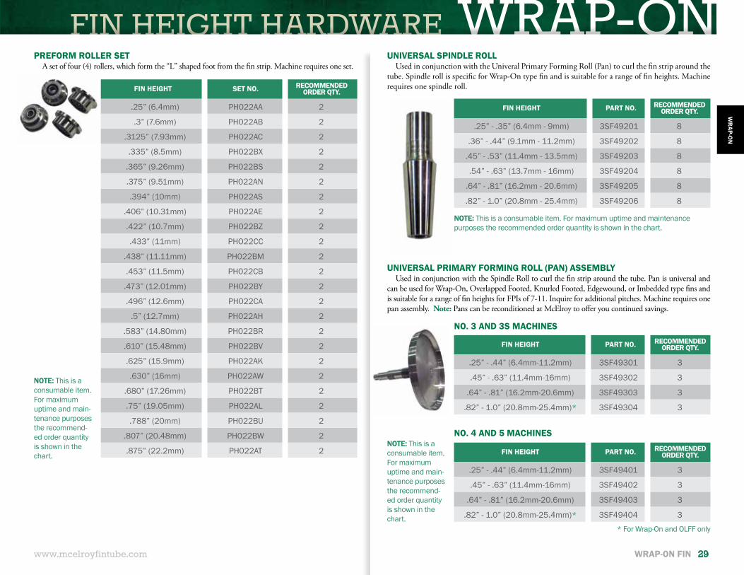
PREFORM ROLLER SET A set of four (4) rollers, which form the “L” shaped foot from the fin strip. Machine requires one set.
FIN HEIGHT SET NO. RECOMMENDED ORDER QTY.
.25” (6.4mm) PH022AA 2
.3” (7.6mm) PH022AB 2
.3125” (7.93mm) PH022AC 2
.335” (8.5mm) PH022BX 2
.365” (9.26mm) PH022BS 2
.375” (9.51mm) PH022AN 2
.394” (10mm) PH022AS 2
.406” (10.31mm) PH022AE 2
.422” (10.7mm) PH022BZ 2
.433” (11mm) PHO22CC 2
.438” (11.11mm) PH022BM 2
.453” (11.5mm) PH022CB 2
.473” (12.01mm) PH022BY 2
.496” (12.6mm) PH022CA 2
.5” (12.7mm) PH022AH 2
.583” (14.80mm) PH022BR 2
.610” (15.48mm) PH022BV 2
.625” (15.9mm) PH022AK 2
.630” (16mm) PH022AW 2
.680” (17.26mm) PH022BT 2
.75” (19.05mm) PH022AL 2
.788” (20mm) PH022BU 2
.807” (20.48mm) PH022BW 2
.875” (22.2mm) PH022AT 2
NOTE: This is a consumable item. For maximum uptime and main-tenance purposes the recommend-ed order quantity is shown in the chart.
NOTE: This is a consumable item. For maximum uptime and maintenance purposes the recommended order quantity is shown in the chart.
NOTE: This is a consumable item. For maximum uptime and main-tenance purposes the recommend-ed order quantity is shown in the chart.
UNIVERSAL SPINDLE ROLLUsed in conjunction with the Univeral Primary Forming Roll (Pan) to curl the fin strip around the
tube. Spindle roll is specific for Wrap-On type fin and is suitable for a range of fin heights. Machine requires one spindle roll.
FIN HEIGHT PART NO. RECOMMENDED ORDER QTY.
.25” - .35” (6.4mm - 9mm) 3SF49201 8
.36” - .44” (9.1mm - 11.2mm) 3SF49202 8
.45” - .53” (11.4mm - 13.5mm) 3SF49203 8
.54” - .63” (13.7mm - 16mm) 3SF49204 8
.64” - .81” (16.2mm - 20.6mm) 3SF49205 8
.82” - 1.0” (20.8mm - 25.4mm) 3SF49206 8
FIN HEIGHT PART NO. RECOMMENDED ORDER QTY.
.25” - .44” (6.4mm-11.2mm) 3SF49301 3
.45” - .63” (11.4mm-16mm) 3SF49302 3
.64” - .81” (16.2mm-20.6mm) 3SF49303 3
.82” - 1.0” (20.8mm-25.4mm)* 3SF49304 3
FIN HEIGHT PART NO. RECOMMENDED ORDER QTY.
.25” - .44” (6.4mm-11.2mm) 3SF49401 3
.45” - .63” (11.4mm-16mm) 3SF49402 3
.64” - .81” (16.2mm-20.6mm) 3SF49403 3
.82” - 1.0” (20.8mm-25.4mm)* 3SF49404 3
UNIVERSAL PRIMARY FORMING ROLL (PAN) ASSEMBLYUsed in conjunction with the Spindle Roll to curl the fin strip around the tube. Pan is universal and
can be used for Wrap-On, Overlapped Footed, Knurled Footed, Edgewound, or Imbedded type fins and is suitable for a range of fin heights for FPIs of 7-11. Inquire for additional pitches. Machine requires one pan assembly. Note: Pans can be reconditioned at McElroy to offer you continued savings.
NO. 3 AND 3S MACHINES
NO. 4 AND 5 MACHINES
* For Wrap-On and OLFF only
WRAP-ON FIN HEIGHT HARDWARE
DESCRIPTION PART NO. RECOMMENDED ORDER QTY.
Universal Strip Guide Clamp 3SF509 1
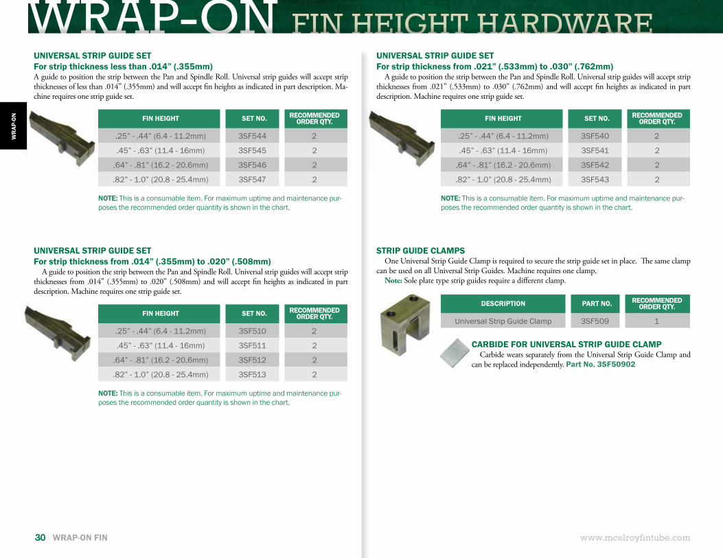
STRIP GUIDE CLAMPSOne Universal Strip Guide Clamp is required to secure the strip guide set in place. The same clamp
can be used on all Universal Strip Guides. Machine requires one clamp.Note: Sole plate type strip guides require a different clamp.
CARBIDE FOR UNIVERSAL STRIP GUIDE CLAMPCarbide wears separately from the Universal Strip Guide Clamp and
can be replaced independently. Part No. 3SF50902
www.mcelroyfintube.com
WR
AP-O
N
30 WRAP-ON FIN
UNIVERSAL STRIP GUIDE SETFor strip thickness from .021” (.533mm) to .030” (.762mm)
A guide to position the strip between the Pan and Spindle Roll. Universal strip guides will accept strip thicknesses from .021” (.533mm) to .030” (.762mm) and will accept fin heights as indicated in part description. Machine requires one strip guide set.
FIN HEIGHT SET NO. RECOMMENDED ORDER QTY.
.25” - .44” (6.4 - 11.2mm) 3SF540 2
.45” - .63” (11.4 - 16mm) 3SF541 2
.64” - .81” (16.2 - 20.6mm) 3SF542 2
.82” - 1.0” (20.8 - 25.4mm) 3SF543 2
NOTE: This is a consumable item. For maximum uptime and maintenance pur-poses the recommended order quantity is shown in the chart.
UNIVERSAL STRIP GUIDE SETFor strip thickness from .014” (.355mm) to .020” (.508mm)
A guide to position the strip between the Pan and Spindle Roll. Universal strip guides will accept strip thicknesses from .014” (.355mm) to .020” (.508mm) and will accept fin heights as indicated in part description. Machine requires one strip guide set.
UNIVERSAL STRIP GUIDE SETFor strip thickness less than .014” (.355mm)A guide to position the strip between the Pan and Spindle Roll. Universal strip guides will accept strip thicknesses of less than .014” (.355mm) and will accept fin heights as indicated in part description. Ma-chine requires one strip guide set.
FIN HEIGHT SET NO. RECOMMENDED ORDER QTY.
.25” - .44” (6.4 - 11.2mm) 3SF510 2
.45” - .63” (11.4 - 16mm) 3SF511 2
.64” - .81” (16.2 - 20.6mm) 3SF512 2
.82” - 1.0” (20.8 - 25.4mm) 3SF513 2
FIN HEIGHT SET NO. RECOMMENDED ORDER QTY.
.25” - .44” (6.4 - 11.2mm) 3SF544 2
.45” - .63” (11.4 - 16mm) 3SF545 2
.64” - .81” (16.2 - 20.6mm) 3SF546 2
.82” - 1.0” (20.8 - 25.4mm) 3SF547 2
NOTE: This is a consumable item. For maximum uptime and maintenance pur-poses the recommended order quantity is shown in the chart.
NOTE: This is a consumable item. For maximum uptime and maintenance pur-poses the recommended order quantity is shown in the chart.
FIN HEIGHT HARDWARE WRAP-ON
www.mcelroyfintube.com
WR
AP-ON
WRAP-ON FIN 31
FINNED OD SET NO. NO. REQ.
.985” (25mm) QFTR04332 1
1.125” (28.56mm) QFTR04324 1
1.25” (31.7mm) QFTR04313 1
1.375” (34.9mm) QFTR04325 1
1.47” (37.3mm) QFTR04327 1
1.5” (38.1mm) QFTR04318 1
1.54” (39.1mm) QFTR04323 1
1.57” (39.8mm) QFTR04328 1
1.625” (41.2mm) QFTR04320 1
1.74” (42.2mm) QFTR04326 1
1.75” (44.4mm) QFTR04305 1
1.8” (45.7mm) QFTR04322 1
1.96” (49.7mm) QFTR04315 1
1.98” (50.3mm) QFTR04306 1
2” (50.8mm) QFTR04307 1
2.24” (56.8mm) QFTR04316 1
2.25” (57.1mm) QFTR04301 1
2.3” (58.4mm) QFTR04334 1
2.48” (62.9mm) QFTR04317 1
2.5” (63.5mm) QFTR04302 1
2.52” (64mm) QFTR04314 1
2.56” (65mm) QFTR04333 1
2.61” (66.24mm) QFTR04310 1
2.75” (69.80mm) QFTR04303 1
2.86” (72.6mm) QFTR04311 1
3” (76.1mm) QFTR04308 1
3.05” (77.6mm) QFTR04330 1
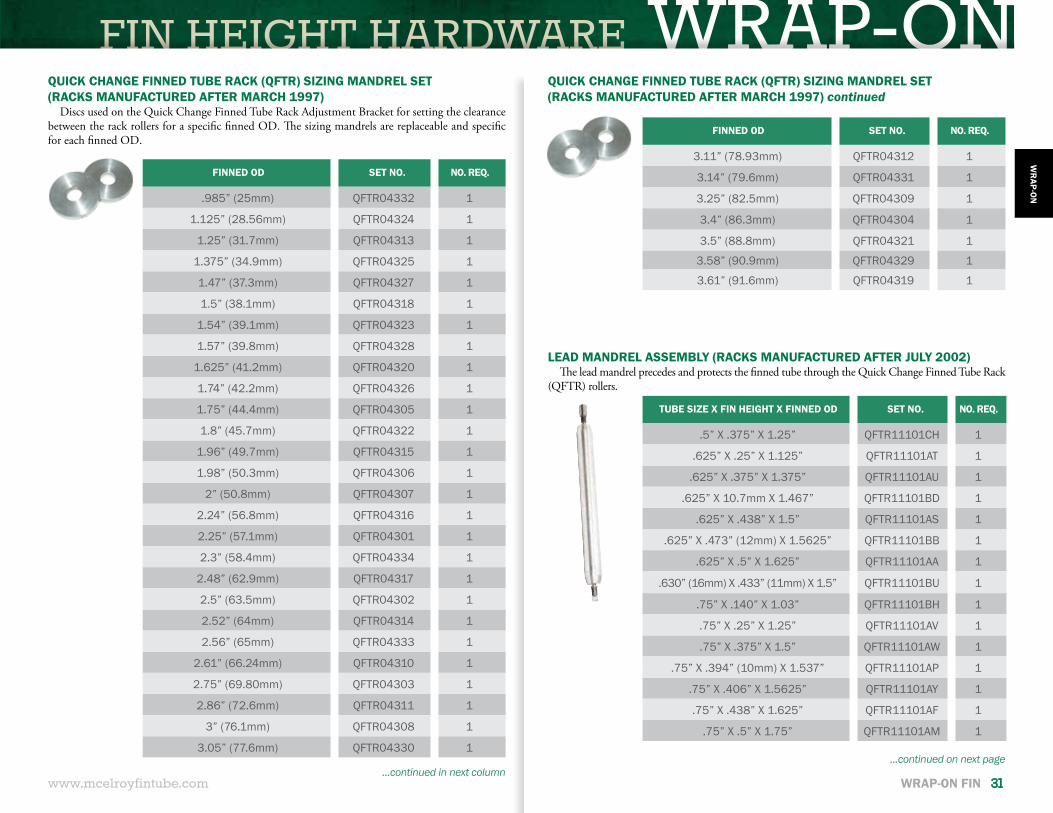
QUICK CHANGE FINNED TUBE RACK (QFTR) SIZING MANDREL SET(RACKS MANUFACTURED AFTER MARCH 1997)
Discs used on the Quick Change Finned Tube Rack Adjustment Bracket for setting the clearance between the rack rollers for a specific finned OD. The sizing mandrels are replaceable and specific for each finned OD.
QUICK CHANGE FINNED TUBE RACK (QFTR) SIZING MANDREL SET(RACKS MANUFACTURED AFTER MARCH 1997) continued
FINNED OD SET NO. NO. REQ.
3.11” (78.93mm) QFTR04312 1
3.14” (79.6mm) QFTR04331 1
3.25” (82.5mm) QFTR04309 1
3.4” (86.3mm) QFTR04304 1
3.5” (88.8mm) QFTR04321 1
3.58” (90.9mm) QFTR04329 1
3.61” (91.6mm) QFTR04319 1
...continued in next column...continued on next page
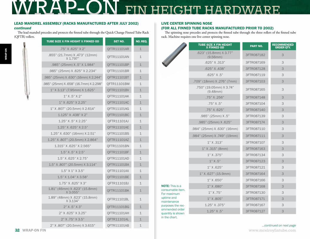
LEAD MANDREL ASSEMBLY (RACKS MANUFACTURED AFTER JULY 2002)The lead mandrel precedes and protects the finned tube through the Quick Change Finned Tube Rack
(QFTR) rollers.
TUBE SIZE X FIN HEIGHT X FINNED OD SET NO. NO. REQ.
.5” X .375” X 1.25” QFTR11101CH 1
.625” X .25” X 1.125” QFTR11101AT 1
.625” X .375” X 1.375” QFTR11101AU 1
.625” X 10.7mm X 1.467” QFTR11101BD 1
.625” X .438” X 1.5” QFTR11101AS 1
.625” X .473” (12mm) X 1.5625” QFTR11101BB 1
.625” X .5” X 1.625” QFTR11101AA 1
.630” (16mm) X .433” (11mm) X 1.5” QFTR11101BU 1
.75” X .140” X 1.03” QFTR11101BH 1
.75” X .25” X 1.25” QFTR11101AV 1
.75” X .375” X 1.5” QFTR11101AW 1
.75” X .394” (10mm) X 1.537” QFTR11101AP 1
.75” X .406” X 1.5625” QFTR11101AY 1
.75” X .438” X 1.625” QFTR11101AF 1
.75” X .5” X 1.75” QFTR11101AM 1
WRAP-ON FIN HEIGHT HARDWARE
www.mcelroyfintube.com
WR
AP-O
N
32 WRAP-ON FIN
TUBE SIZE X FIN HEIGHT X FINNED OD SET NO. NO. REQ.
.75” X .625” X 2” QFTR11101AR 1
.855” (21.7mm) X .473” (12mm) X 1.797” QFTR11101AN 1
.985” (25mm) X .5” X 1.984” QFTR11101BP 1
.985” (25mm) X .625” X 2.234” QFTR11101BR 1
.985” (25mm) X .630” (16mm) X 2.244” QFTR11101BT 1
.985” (25mm) X .658” (16.7mm) X 2.298” QFTR11101BM 1
1” X 3.13” (7.95mm) X 1.625” QFTR11101BV 1
1” X .5” X 2” QFTR11101AK 1
1” X .625” X 2.25” QFTR11101AC 1
1” X .807” (20.5mm) X 2.614” QFTR11101AG 1
1.125” X .438” X 2” QFTR11101BC 1
1.25” X .5” X 2.25” QFTR11101AJ 1
1.25” X .625” X 2.5” QFTR11101AE 1
1.25” X .630” (16mm) X 2.51” QFTR11101BS 1
1.25” X .807” (20.5mm) X 2.864” QFTR11101AZ 1
1.315” X .625” X 2.565” QFTR11101BN 1
1.5” X .5” X 2.5” QFTR11101BF 1
1.5” X .625” X 2.75” QFTR11101AD 1
1.5” X .807” (20.5mm) X 3.114” QFTR11101BA 1
1.5” X 1” X 3.5” QFTR11101AX 1
1.5” X 1.04” X 3.58” QFTR11101BE 1
1.75” X .625” X 3” QFTR11101BJ 11.81” (46mm) X .623” (15.8mm)
X 3.055” QFTR11101BK 1
1.89” (48mm) X .623” (15.8mm) X 3.134” QFTR11101BL 1
2” X .5” X 3” QFTR11101BG 1
2” X .625” X 3.25” QFTR11101AH 1
2” X .75” X 3.5” QFTR11101AL 1
2” X .807” (20.5mm) X 3.615” QFTR11101AB 1
TUBE SIZE X FIN HEIGHTX FINNED OD PART NO. RECOMMENDED
ORDER QTY.
.623” (15.8mm) X 3.77” (9.56mm) 3FTR087182 3
.625” X .313” 3FTR087169 3
.625” X .438” 3FTR087128 3
.625” X .5” 3FTR087119 3
.709” (18mm) X .276” (7mm) 3FTR087103 3
.750” (19.05mm) X 3.74” (9.48mm) 3FTR087165 3
.75” X .256” 3FTR087148 3
.75” X .5” 3FTR087104 3
.75” X .625” 3FTR087140 3
.985” (25mm) X .5” 3FTR087139 3
.985” (25mm) X .625” 3FTR087174 3
.984” (25mm) X .630” (16mm) 3FTR087110 3
.984” (25mm) X .749” (19mm) 3FTR087111 3
1” X .313” 3FTR087107 3
1” X .315” (8mm) 3FTR087163 3
1” X .375” 3FTR087134 3
1” X .5” 3FTR087123 3
1” X .625” 3FTR087121 3
1” X .627” (15.9mm) 3FTR087164 3
1” X .650” 3FTR087166 3
1” X .680” 3FTR087168 3
1” X .75” 3FTR087130 3
1” X .805” 3FTR087171 3
1.25” X .375” 3FTR087167 3
1.25” X .5” 3FTR087127 3
LEAD MANDREL ASSEMBLY (RACKS MANUFACTURED AFTER JULY 2002)continued
The lead mandrel precedes and protects the finned tube through the Quick Change Finned Tube Rack (QFTR) rollers.
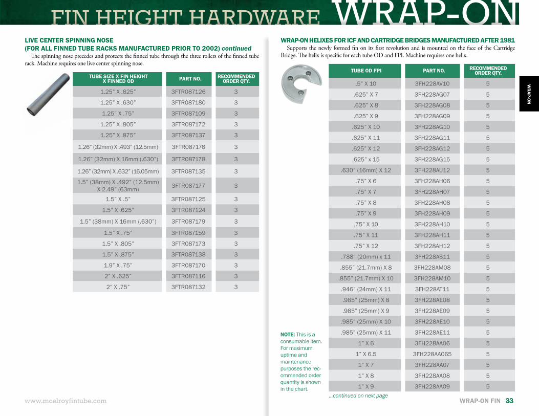
LIVE CENTER SPINNING NOSE(FOR ALL FINNED TUBE RACKS MANUFACTURED PRIOR TO 2002)
The spinning nose precedes and protects the finned tube through the three rollers of the finned tube rack. Machine requires one live center spinning nose.
NOTE: This is a consumable item. For maximum uptime and maintenance purposes the rec-ommended order quantity is shown in the chart.
...continued on next page
FIN HEIGHT HARDWARE WRAP-ONTUBE OD FPI PART NO. RECOMMENDED
ORDER QTY.
.5” X 10 3FH228AV10 5
.625” X 7 3FH228AG07 5
.625” X 8 3FH228AG08 5
.625” X 9 3FH228AG09 5
.625” X 10 3FH228AG10 5
.625” X 11 3FH228AG11 5
.625” X 12 3FH228AG12 5
.625” x 15 3FH228AG15 5
.630” (16mm) X 12 3FH228AU12 5
.75” X 6 3FH228AH06 5
.75” X 7 3FH228AH07 5
.75” X 8 3FH228AH08 5
.75” X 9 3FH228AH09 5
.75” X 10 3FH228AH10 5
.75” X 11 3FH228AH11 5
.75” X 12 3FH228AH12 5
.788” (20mm) x 11 3FH228AS11 5
.855” (21.7mm) X 8 3FH228AM08 5
.855” (21.7mm) X 10 3FH228AM10 5
.946” (24mm) X 11 3FH228AT11 5
.985” (25mm) X 8 3FH228AE08 5
.985” (25mm) X 9 3FH228AE09 5
.985” (25mm) X 10 3FH228AE10 5
.985” (25mm) X 11 3FH228AE11 5
1” X 6 3FH228AA06 5
1” X 6.5 3FH228AA065 5
1” X 7 3FH228AA07 5
1” X 8 3FH228AA08 5
1” X 9 3FH228AA09 5
NOTE: This is a consumable item. For maximum uptime and maintenance purposes the rec-ommended order quantity is shown in the chart.
TUBE SIZE X FIN HEIGHT X FINNED OD PART NO. RECOMMENDED
ORDER QTY.
1.25” X .625” 3FTR087126 3
1.25” X .630” 3FTR087180 3
1.25” X .75” 3FTR087109 3
1.25” X .805” 3FTR087172 3
1.25” X .875” 3FTR087137 3
1.26” (32mm) X .493” (12.5mm) 3FTR087176 3
1.26” (32mm) X 16mm (.630”) 3FTR087178 3
1.26” (32mm) X .632” (16.05mm) 3FTR087135 3
1.5” (38mm) X .492” (12.5mm) X 2.49” (63mm) 3FTR087177 3
1.5” X .5” 3FTR087125 3
1.5” X .625” 3FTR087124 3
1.5” (38mm) X 16mm (.630”) 3FTR087179 3
1.5” X .75” 3FTR087159 3
1.5” X .805” 3FTR087173 3
1.5” X .875” 3FTR087138 3
1.9” X .75” 3FTR087170 3
2” X .625” 3FTR087116 3
2” X .75” 3FTR087132 3
WRAP-ON HELIXES FOR ICF AND CARTRIDGE BRIDGES MANUFACTURED AFTER 1981Supports the newly formed fin on its first revolution and is mounted on the face of the Cartridge
Bridge. The helix is specific for each tube OD and FPI. Machine requires one helix.
LIVE CENTER SPINNING NOSE(FOR ALL FINNED TUBE RACKS MANUFACTURED PRIOR TO 2002) continued
The spinning nose precedes and protects the finned tube through the three rollers of the finned tube rack. Machine requires one live center spinning nose.
...continued on next pagewww.mcelroyfintube.com
WR
AP-ON
WRAP-ON FIN 33
WRAP-ON FIN HEIGHT HARDWARE
www.mcelroyfintube.com
WR
AP-O
N
34 WRAP-ON FIN
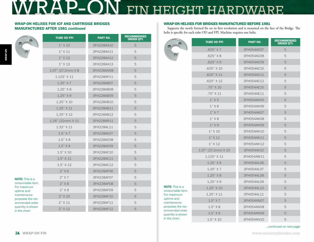
WRAP-ON HELIXES FOR ICF AND CARTRIDGE BRIDGESMANUFACTURED AFTER 1981 continued
WRAP-ON HELIXES FOR BRIDGES MANUFACTURED BEFORE 1981Supports the newly formed fin on its first revolution and is mounted on the face of the Bridge. The
helix is specific for each tube OD and FPI. Machine requires one helix.
NOTE: This is a consumable item. For maximum uptime and maintenance purposes the rec-ommended order quantity is shown in the chart.
NOTE: This is a consumable item. For maximum uptime and maintenance purposes the rec-ommended order quantity is shown in the chart.
TUBE OD FPI PART NO. RECOMMENDED ORDER QTY.
1” X 10 3FH228AA10 5
1” X 11 3FH228AA11 5
1” X 12 3FH228AA12 5
1” X 13 3FH228AA13 5
1.07” (27.2mm) X 8 3FH228AN08 5
1.125” X 11 3FH228AP11 5
1.25” X 7 3FH228AB07 5
1.25” X 8 3FH228AB08 5
1.25” X 9 3FH228AB09 5
1.25” X 10 3FH228AB10 5
1.25” X 11 3FH228AB11 5
1.25” X 12 3FH228AB12 5
1.26” (32mm) X 11 3FH228AR11 5
1.32” X 11 3FH228AL11 5
1.5” X 7 3FH228AC07 5
1.5” X 8 3FH228AC08 5
1.5” X 9 3FH228AC09 5
1.5” X 10 3FH228AC10 5
1.5” X 11 3FH228AC11 5
1.5” X 12 3FH228AC12 5
2” X 6 3FH228AF06 5
2” X 7 3FH228AF07 5
2” X 8 3FH228AF08 5
2” X 9 3FH228AF09 5
2” X 10 3FH228AF10 5
2” X 11 3FH228AF11 5
2” X 12 3FH228AF12 5
TUBE OD FPI PART NO. RECOMMENDED ORDER QTY.
.625” X 7 3FH054AC07 5
.625” X 8 3FH054AC08 5
.625” X 9 3FH054AC09 5
.625” X 10 3FH054AC10 5
.625” X 11 3FH054AC11 5
.625” X 12 3FH054AC12 5
.75” X 10 3FH054AE10 5
.75” X 11 3FH054AE11 5
1” X 5 3FH054AK05 5
1” X 6 3FH054AK06 5
1” X 7 3FH054AK07 5
1” X 8 3FH054AK08 5
1” X 9 3FH054AK09 5
1” X 10 3FH054AK10 5
1” X 11 3FH054AK11 5
1” X 12 3FH054AK12 5
1.07” (27.2mm) X 10 3FH054AV10 5
1.125” X 11 3FH054AW11 5
1.25” X 6 3FH054AL06 5
1.25” X 7 3FH054AL07 5
1.25” X 8 3FH054AL08 5
1.25” X 9 3FH054AL09 5
1.25” X 10 3FH054AL10 5
1.25” X 11 3FH054AL11 5
1.5” X 7 3FH054AN07 5
1.5” X 8 3FH054AN08 5
1.5” X 9 3FH054AN09 5
1.5” X 10 3FH054AN10 5
...continued on next page
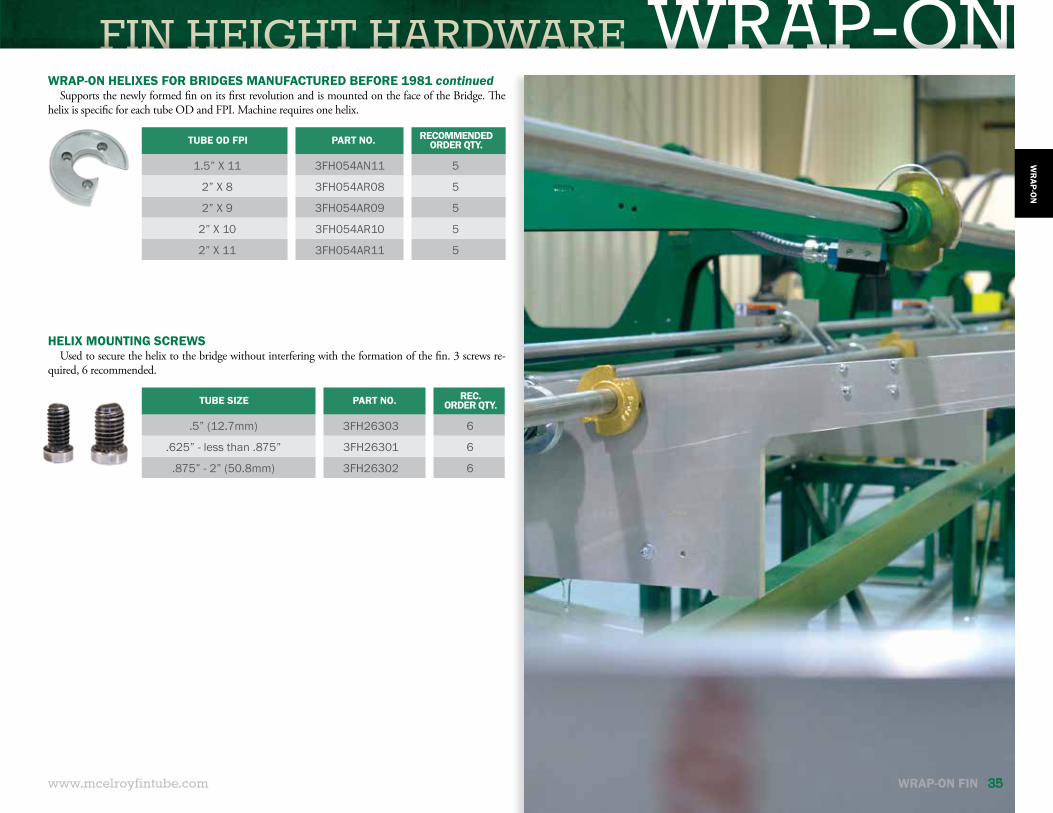
FIN HEIGHT HARDWARE WRAP-ON
www.mcelroyfintube.com WRAP-ON FIN 35
WR
AP-ON
WRAP-ON HELIXES FOR BRIDGES MANUFACTURED BEFORE 1981 continuedSupports the newly formed fin on its first revolution and is mounted on the face of the Bridge. The
helix is specific for each tube OD and FPI. Machine requires one helix.
HELIX MOUNTING SCREWSUsed to secure the helix to the bridge without interfering with the formation of the fin. 3 screws re-
quired, 6 recommended.
TUBE OD FPI PART NO. RECOMMENDED ORDER QTY.
1.5” X 11 3FH054AN11 5
2” X 8 3FH054AR08 5
2” X 9 3FH054AR09 5
2” X 10 3FH054AR10 5
2” X 11 3FH054AR11 5
TUBE SIZE PART NO. REC. ORDER QTY.
.5” (12.7mm) 3FH26303 6
.625” - less than .875” 3FH26301 6
.875” - 2” (50.8mm) 3FH26302 6

OVERLAPPED FOOTED FIN
FIND:STRIP WIDTHFINNED ODFIN TIP THICKNESSWEIGHTS OF FIN MATERIAL
McELROY FINTUBE CALCULATORWEB AND MOBILE APPS
www.mcelroyfintube.com36 www.mcelroyfintube.com
www.mcelroy.com/fintube/resources.htm
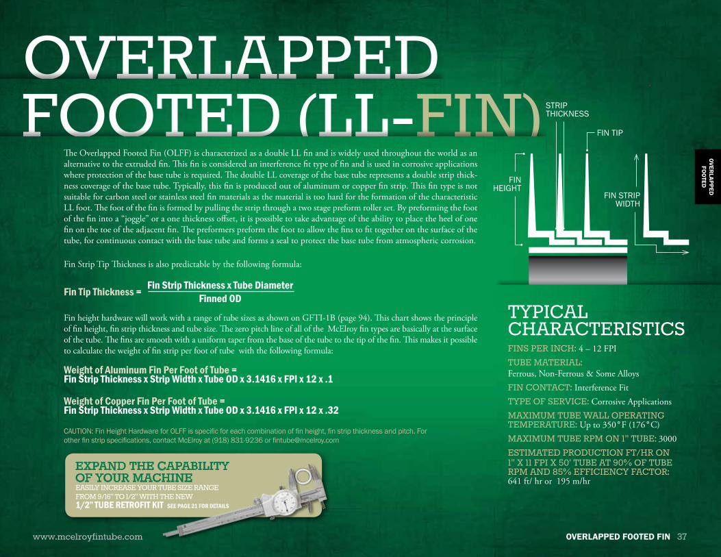
FIN HEIGHT HARDWARE OLFFHEIGHT HARDWARE OLFFOVERLAPPEDFOOTED (LL-FIN)
www.mcelroyfintube.com
OVERLAPPED
FOO
TED
OVERLAPPED FOOTED FIN 37
FIN TIP
STRIP THICKNESS
FINS PER INCH: 4 – 12 FPITUBE MATERIAL: Ferrous, Non-Ferrous & Some AlloysFIN CONTACT: Interference FitTYPE OF SERVICE: Corrosive ApplicationsMAXIMUM TUBE WALL OPERATING TEMPERATURE: Up to 350°F (176°C)MAXIMUM TUBE RPM ON 1” TUBE: 3000ESTIMATED PRODUCTION FT/HR ON1” X 11 FPI X 50’ TUBE AT 90% OF TUBE RPM AND 85% EFFICIENCY FACTOR: 641 ft/ hr or 195 m/hr
TYPICALCHARACTERISTICS
The Overlapped Footed Fin (OLFF) is characterized as a double LL fin and is widely used throughout the world as an alternative to the extruded fin. This fin is considered an interference fit type of fin and is used in corrosive applications where protection of the base tube is required. The double LL coverage of the base tube represents a double strip thick-ness coverage of the base tube. Typically, this fin is produced out of aluminum or copper fin strip. This fin type is not suitable for carbon steel or stainless steel fin materials as the material is too hard for the formation of the characteristic LL foot. The foot of the fin is formed by pulling the strip through a two stage preform roller set. By preforming the foot of the fin into a “joggle” or a one thickness offset, it is possible to take advantage of the ability to place the heel of one fin on the toe of the adjacent fin. The preformers preform the foot to allow the fins to fit together on the surface of the tube, for continuous contact with the base tube and forms a seal to protect the base tube from atmospheric corrosion.
Fin Strip Tip Thickness is also predictable by the following formula:
Fin height hardware will work with a range of tube sizes as shown on GFTI-1B (page 94). This chart shows the principle of fin height, fin strip thickness and tube size. The zero pitch line of all of the McElroy fin types are basically at the surface of the tube. The fins are smooth with a uniform taper from the base of the tube to the tip of the fin. This makes it possible to calculate the weight of fin strip per foot of tube with the following formula:
Weight of Aluminum Fin Per Foot of Tube =Fin Strip Thickness x Strip Width x Tube OD x 3.1416 x FPI x 12 x .1
Weight of Copper Fin Per Foot of Tube =Fin Strip Thickness x Strip Width x Tube OD x 3.1416 x FPI x 12 x .32
Fin Tip Thickness = Fin Strip Thickness x Tube DiameterFinned OD
CAUTION: Fin Height Hardware for OLFF is specific for each combination of fin height, fin strip thickness and pitch. For other fin strip specifications, contact McElroy at (918) 831-9236 or [email protected]
FIN STRIP WIDTH
FIN HEIGHT
EXPAND THE CAPABILITY OF YOUR MACHINEEASILY INCREASE YOUR TUBE SIZE RANGE FROM 9/16” TO 1/2” WITH THE NEW 1/2” TUBE RETROFIT KIT SEE PAGE 21 FOR DETAILS
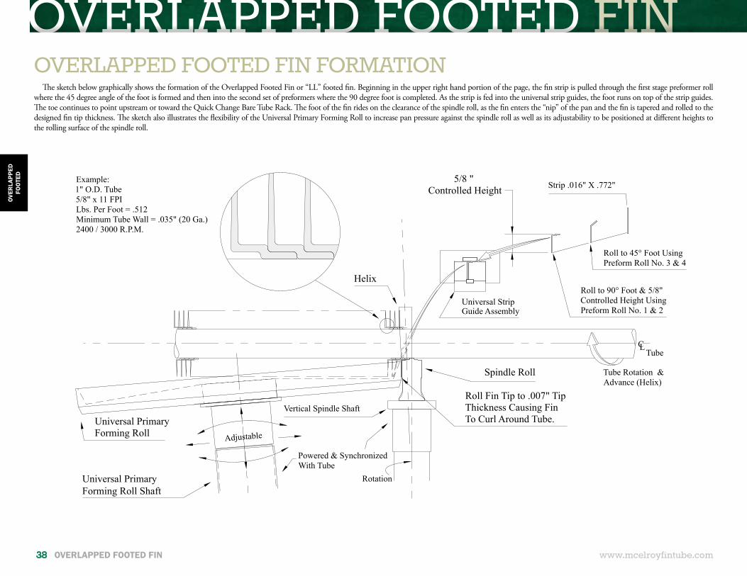
OVERLAPPED FOOTED FIN
5/8 " Controlled Height
Universal StripGuide Assembly
Roll to 90° Foot & 5/8"Controlled Height UsingPreform Roll No. 1 & 2
Roll to 45° Foot UsingPreform Roll No. 3 & 4
Strip .016" X .772"
Powered & SynchronizedWith Tube
Adjustable
Example:1" O.D. Tube5/8" x 11 FPILbs. Per Foot = .512Minimum Tube Wall = .035" (20 Ga.)2400 / 3000 R.P.M.
Helix
Spindle Roll
Roll Fin Tip to .007" TipThickness Causing FinTo Curl Around Tube.
Vertical Spindle Shaft
Universal PrimaryForming Roll Shaft
Universal Primary Forming Roll
CLTube
Rotation
Tube Rotation &Advance (Helix)
www.mcelroyfintube.com
OVER
LAPP
EDFO
OTE
D
38 OVERLAPPED FOOTED FIN
OVERLAPPED FOOTED FIN FORMATIONThe sketch below graphically shows the formation of the Overlapped Footed Fin or “LL” footed fin. Beginning in the upper right hand portion of the page, the fin strip is pulled through the first stage preformer roll
where the 45 degree angle of the foot is formed and then into the second set of preformers where the 90 degree foot is completed. As the strip is fed into the universal strip guides, the foot runs on top of the strip guides. The toe continues to point upstream or toward the Quick Change Bare Tube Rack. The foot of the fin rides on the clearance of the spindle roll, as the fin enters the “nip” of the pan and the fin is tapered and rolled to the designed fin tip thickness. The sketch also illustrates the flexibility of the Universal Primary Forming Roll to increase pan pressure against the spindle roll as well as its adjustability to be positioned at different heights to the rolling surface of the spindle roll.
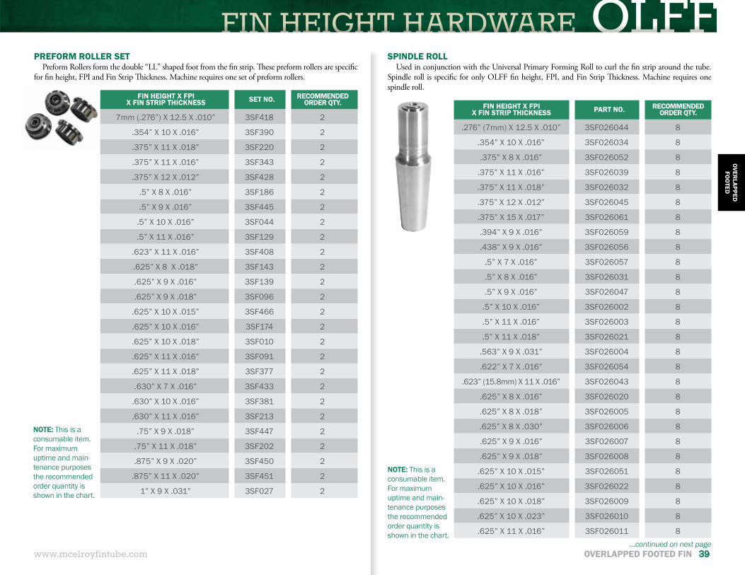
FIN HEIGHT HARDWARE OLFF
www.mcelroyfintube.com
OVERLAPPED
FOO
TED
OVERLAPPED FOOTED FIN 39
PREFORM ROLLER SETPreform Rollers form the double “LL” shaped foot from the fin strip. These preform rollers are specific
for fin height, FPI and Fin Strip Thickness. Machine requires one set of preform rollers.
FIN HEIGHT X FPI X FIN STRIP THICKNESS SET NO. RECOMMENDED
ORDER QTY.
7mm (.276”) X 12.5 X .010” 3SF418 2
.354” X 10 X .016” 3SF390 2
.375” X 11 X .018” 3SF220 2
.375” X 11 X .016” 3SF343 2
.375” X 12 X .012” 3SF428 2
.5” X 8 X .016” 3SF186 2
.5” X 9 X .016” 3SF445 2
.5” X 10 X .016” 3SF044 2
.5” X 11 X .016” 3SF129 2
.623” X 11 X .016” 3SF408 2
.625” X 8 X .018” 3SF143 2
.625” X 9 X .016” 3SF139 2
.625” X 9 X .018” 3SF096 2
.625” X 10 X .015” 3SF466 2
.625” X 10 X .016” 3SF174 2
.625” X 10 X .018” 3SF010 2
.625” X 11 X .016” 3SF091 2
.625” X 11 X .018” 3SF377 2
.630” X 7 X .016” 3SF433 2
.630” X 10 X .016” 3SF381 2
.630” X 11 X .016” 3SF213 2
.75” X 9 X .018” 3SF447 2
.75” X 11 X .018” 3SF202 2
.875” X 9 X .020” 3SF450 2
.875” X 11 X .020” 3SF451 2
1” X 9 X .031” 3SF027 2
NOTE: This is a consumable item. For maximum uptime and main-tenance purposes the recommended order quantity is shown in the chart.
SPINDLE ROLLUsed in conjunction with the Universal Primary Forming Roll to curl the fin strip around the tube.
Spindle roll is specific for only OLFF fin height, FPI, and Fin Strip Thickness. Machine requires one spindle roll.
NOTE: This is a consumable item. For maximum uptime and main-tenance purposes the recommended order quantity is shown in the chart.
FIN HEIGHT X FPIX FIN STRIP THICKNESS PART NO. RECOMMENDED
ORDER QTY.
.276” (7mm) X 12.5 X .010” 3SF026044 8
.354” X 10 X .016” 3SF026034 8
.375” X 8 X .016” 3SF026052 8
.375” X 11 X .016” 3SF026039 8
.375” X 11 X .018” 3SF026032 8
.375” X 12 X .012” 3SF026045 8
.375” X 15 X .017” 3SF026061 8
.394” X 9 X .016” 3SF026059 8
.438” X 9 X .016” 3SF026056 8
.5” X 7 X .016” 3SF026057 8
.5” X 8 X .016” 3SF026031 8
.5” X 9 X .016” 3SF026047 8
.5” X 10 X .016” 3SF026002 8
.5” X 11 X .016” 3SF026003 8
.5” X 11 X .018” 3SF026021 8
.563” X 9 X .031” 3SF026004 8
.622” X 7 X .016” 3SF026054 8
.623” (15.8mm) X 11 X .016” 3SF026043 8
.625” X 8 X .016” 3SF026020 8
.625” X 8 X .018” 3SF026005 8
.625” X 8 X .030” 3SF026006 8
.625” X 9 X .016” 3SF026007 8
.625” X 9 X .018” 3SF026008 8
.625” X 10 X .015” 3SF026051 8
.625” X 10 X .016” 3SF026022 8
.625” X 10 X .018” 3SF026009 8
.625” X 10 X .023” 3SF026010 8
.625” X 11 X .016” 3SF026011 8...continued on next page
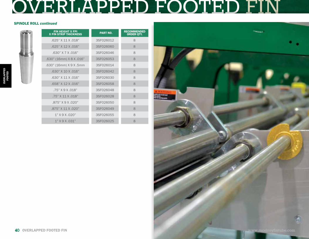
OVERLAPPED FOOTED FIN
www.mcelroyfintube.com
OVER
LAPP
EDFO
OTE
D
40 OVERLAPPED FOOTED FIN
SPINDLE ROLL continued
FIN HEIGHT X FPIX FIN STRIP THICKNESS PART NO. RECOMMENDED
ORDER QTY.
.625” X 11 X .018” 3SF026012 8
.625” X 12 X .016” 3SF026060 8
.630” X 7 X .016” 3SF026046 8
.630” (16mm) X 8 X .016” 3SF026053 8
.630” (16mm) X 9 X .5mm 3SF026014 8
.630” X 10 X .016” 3SF026042 8
.630” X 11 X .016” 3SF026030 8
.658” X 12 X .016” 3SF026058 8
.75” X 9 X .018” 3SF026048 8
.75” X 11 X .018” 3SF026028 8
.875” X 9 X .020” 3SF026050 8
.875” X 11 X .020” 3SF026049 8
1” X 9 X .020” 3SF026055 8
1” X 9 X .031” 3SF026025 8
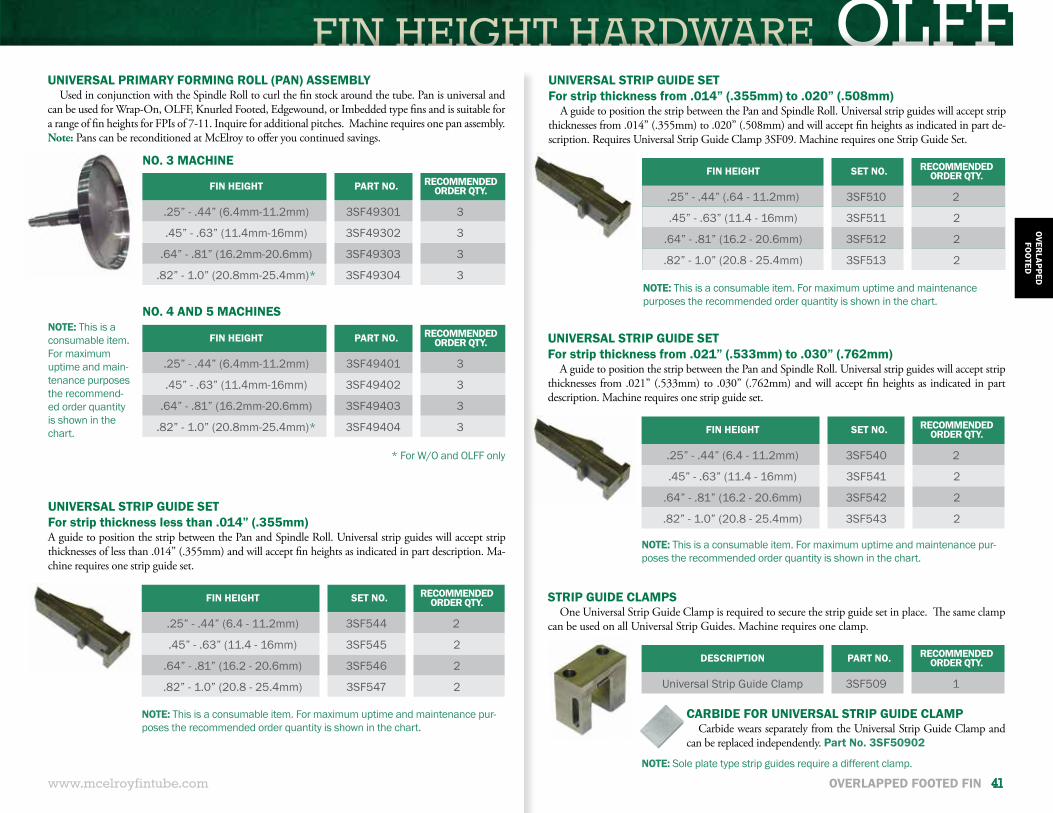
FIN HEIGHT HARDWARE OLFF
www.mcelroyfintube.com
OVERLAPPED
FOO
TED
OVERLAPPED FOOTED FIN 41
UNIVERSAL STRIP GUIDE SETFor strip thickness from .014” (.355mm) to .020” (.508mm)
A guide to position the strip between the Pan and Spindle Roll. Universal strip guides will accept strip thicknesses from .014” (.355mm) to .020” (.508mm) and will accept fi n heights as indicated in part de-scription. Requires Universal Strip Guide Clamp 3SF09. Machine requires one Strip Guide Set.
FIN HEIGHT SET NO. RECOMMENDEDORDER QTY.
.25” - .44” (.64 - 11.2mm) 3SF510 2
.45” - .63” (11.4 - 16mm) 3SF511 2
.64” - .81” (16.2 - 20.6mm) 3SF512 2
.82” - 1.0” (20.8 - 25.4mm) 3SF513 2
NOTE: This is a consumable item. For maximum uptime and maintenance purposes the recommended order quantity is shown in the chart.
UNIVERSAL STRIP GUIDE SETFor strip thickness from .021” (.533mm) to .030” (.762mm)
A guide to position the strip between the Pan and Spindle Roll. Universal strip guides will accept strip thicknesses from .021” (.533mm) to .030” (.762mm) and will accept fin heights as indicated in part description. Machine requires one strip guide set.
FIN HEIGHT SET NO. RECOMMENDED ORDER QTY.
.25” - .44” (6.4 - 11.2mm) 3SF540 2
.45” - .63” (11.4 - 16mm) 3SF541 2
.64” - .81” (16.2 - 20.6mm) 3SF542 2
.82” - 1.0” (20.8 - 25.4mm) 3SF543 2
NOTE: This is a consumable item. For maximum uptime and maintenance pur-poses the recommended order quantity is shown in the chart.
FIN HEIGHT PART NO. RECOMMENDEDORDER QTY.
.25” - .44” (6.4mm-11.2mm) 3SF49301 3
.45” - .63” (11.4mm-16mm) 3SF49302 3
.64” - .81” (16.2mm-20.6mm) 3SF49303 3
.82” - 1.0” (20.8mm-25.4mm)* 3SF49304 3
FIN HEIGHT PART NO. RECOMMENDEDORDER QTY.
.25” - .44” (6.4mm-11.2mm) 3SF49401 3
.45” - .63” (11.4mm-16mm) 3SF49402 3
.64” - .81” (16.2mm-20.6mm) 3SF49403 3
.82” - 1.0” (20.8mm-25.4mm)* 3SF49404 3
UNIVERSAL PRIMARY FORMING ROLL (PAN) ASSEMBLYUsed in conjunction with the Spindle Roll to curl the fi n stock around the tube. Pan is universal and
can be used for Wrap-On, OLFF, Knurled Footed, Edgewound, or Imbedded type fi ns and is suitable for a range of fi n heights for FPIs of 7-11. Inquire for additional pitches. Machine requires one pan assembly. Note: Pans can be reconditioned at McElroy to off er you continued savings.
NO. 3 MACHINE
NO. 4 AND 5 MACHINES
* For W/O and OLFF only
NOTE: This is a consumable item. For maximum uptime and main-tenance purposes the recommend-ed order quantity is shown in the chart.
DESCRIPTION PART NO. RECOMMENDED ORDER QTY.
Universal Strip Guide Clamp 3SF509 1
STRIP GUIDE CLAMPSOne Universal Strip Guide Clamp is required to secure the strip guide set in place. The same clamp
can be used on all Universal Strip Guides. Machine requires one clamp.
CARBIDE FOR UNIVERSAL STRIP GUIDE CLAMPCarbide wears separately from the Universal Strip Guide Clamp and
can be replaced independently. Part No. 3SF50902
UNIVERSAL STRIP GUIDE SETFor strip thickness less than .014” (.355mm)A guide to position the strip between the Pan and Spindle Roll. Universal strip guides will accept strip thicknesses of less than .014” (.355mm) and will accept fin heights as indicated in part description. Ma-chine requires one strip guide set.
FIN HEIGHT SET NO. RECOMMENDED ORDER QTY.
.25” - .44” (6.4 - 11.2mm) 3SF544 2
.45” - .63” (11.4 - 16mm) 3SF545 2
.64” - .81” (16.2 - 20.6mm) 3SF546 2
.82” - 1.0” (20.8 - 25.4mm) 3SF547 2
NOTE: This is a consumable item. For maximum uptime and maintenance pur-poses the recommended order quantity is shown in the chart.
NOTE: Sole plate type strip guides require a different clamp.
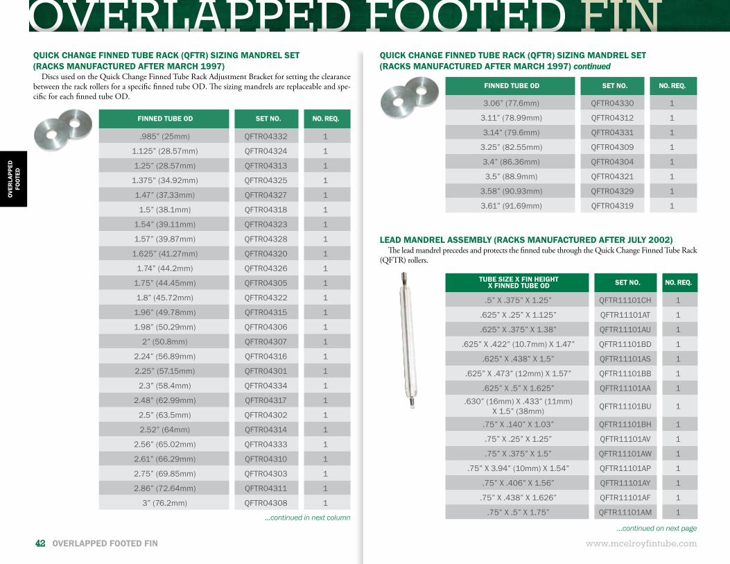
OVERLAPPED FOOTED FIN
www.mcelroyfintube.com
OVER
LAPP
EDFO
OTE
D
42 OVERLAPPED FOOTED FIN
LEAD MANDREL ASSEMBLY (RACKS MANUFACTURED AFTER JULY 2002)The lead mandrel precedes and protects the finned tube through the Quick Change Finned Tube Rack
(QFTR) rollers.
TUBE SIZE X FIN HEIGHT X FINNED TUBE OD SET NO. NO. REQ.
.5” X .375” X 1.25” QFTR11101CH 1
.625” X .25” X 1.125” QFTR11101AT 1
.625” X .375” X 1.38” QFTR11101AU 1
.625” X .422” (10.7mm) X 1.47” QFTR11101BD 1
.625” X .438” X 1.5” QFTR11101AS 1
.625” X .473” (12mm) X 1.57” QFTR11101BB 1
.625” X .5” X 1.625” QFTR11101AA 1.630” (16mm) X .433” (11mm)
X 1.5” (38mm) QFTR11101BU 1
.75” X .140” X 1.03” QFTR11101BH 1
.75” X .25” X 1.25” QFTR11101AV 1
.75” X .375” X 1.5” QFTR11101AW 1
.75” X 3.94” (10mm) X 1.54” QFTR11101AP 1
.75” X .406” X 1.56” QFTR11101AY 1
.75” X .438” X 1.626” QFTR11101AF 1
.75” X .5” X 1.75” QFTR11101AM 1
FINNED TUBE OD SET NO. NO. REQ.
.985” (25mm) QFTR04332 1
1.125” (28.57mm) QFTR04324 1
1.25” (28.57mm) QFTR04313 1
1.375” (34.92mm) QFTR04325 1
1.47” (37.33mm) QFTR04327 1
1.5” (38.1mm) QFTR04318 1
1.54” (39.11mm) QFTR04323 1
1.57” (39.87mm) QFTR04328 1
1.625” (41.27mm) QFTR04320 1
1.74” (44.2mm) QFTR04326 1
1.75” (44.45mm) QFTR04305 1
1.8” (45.72mm) QFTR04322 1
1.96” (49.78mm) QFTR04315 1
1.98” (50.29mm) QFTR04306 1
2” (50.8mm) QFTR04307 1
2.24” (56.89mm) QFTR04316 1
2.25” (57.15mm) QFTR04301 1
2.3” (58.4mm) QFTR04334 1
2.48” (62.99mm) QFTR04317 1
2.5” (63.5mm) QFTR04302 1
2.52” (64mm) QFTR04314 1
2.56” (65.02mm) QFTR04333 1
2.61” (66.29mm) QFTR04310 1
2.75” (69.85mm) QFTR04303 1
2.86” (72.64mm) QFTR04311 1
3” (76.2mm) QFTR04308 1
QUICK CHANGE FINNED TUBE RACK (QFTR) SIZING MANDREL SET(RACKS MANUFACTURED AFTER MARCH 1997)
Discs used on the Quick Change Finned Tube Rack Adjustment Bracket for setting the clearance between the rack rollers for a specific finned tube OD. The sizing mandrels are replaceable and spe-cific for each finned tube OD.
...continued in next column
QUICK CHANGE FINNED TUBE RACK (QFTR) SIZING MANDREL SET(RACKS MANUFACTURED AFTER MARCH 1997) continued
FINNED TUBE OD SET NO. NO. REQ.
3.06” (77.6mm) QFTR04330 1
3.11” (78.99mm) QFTR04312 1
3.14” (79.6mm) QFTR04331 1
3.25” (82.55mm) QFTR04309 1
3.4” (86.36mm) QFTR04304 1
3.5” (88.9mm) QFTR04321 1
3.58” (90.93mm) QFTR04329 1
3.61” (91.69mm) QFTR04319 1
...continued on next page
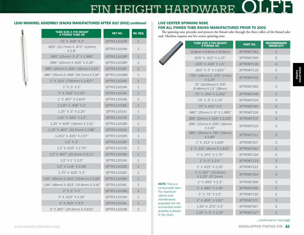
FIN HEIGHT HARDWARE OLFF
www.mcelroyfintube.com
OVERLAPPED
FOO
TED
OVERLAPPED FOOTED FIN 43
TUBE SIZE X FIN HEIGHT X FINNED TUBE OD SET NO. NO. REQ.
.75” X .625” X 2” QFTR11101AR 1.855” (21.7mm) X .473” (12mm)
X 1.8” QFTR11101AN 1
.985” (25mm) X .5” X 1.985” QFTR11101BP 1
.985” (25mm) X .625” X 2.24” QFTR11101BR 1
.985” (25mm) X .630” (16mm) X 2.25” QFTR11101BT 1
.985” (25mm) X .658” (16.7mm) X 2.30” QFTR11101BM 1
1” X .313” (7.95mm) X 1.627” QFTR11101BV 1
1” X .5” X 2” QFTR11101AK 1
1” X .625” X 2.25” QFTR11101AC 1
1” X .807” X 2.614” QFTR11101AG 1
1.125” X .438” X 2” QFTR11101BC 1
1.25” X .5” X 2.25” QFTR11101AJ 1
1.25” X .625” X 2.5” QFTR11101AE 1
1.25” X .630” (16mm) X 2.51” QFTR11101BS 1
1.25” X .807” (20.5mm) X 2.86” QFTR11101AZ 1
1.315” X .625” X 2.57” QFTR11101BN 1
1.5” X .5” QFTR11101BF 1
1.5” X .625” X 2.75” QFTR11101AD 1
1.5” X .807” (20.5mm) X 3.11” QFTR11101BA 1
1.5” X 1” X 2.5” QFTR11101AX 1
1.5” X 1.04” X 3.58” QFTR11101BE 1
1.75” X .625” X 3” QFTR11101BJ 1
1.81” (46mm) X .623” (15.8mm) X 3.06” QFTR11101BK 1
1.89” (48mm) X .623” (15.8mm) X 3.14” QFTR11101BL 1
2” X .5” X 3” QFTR11101BG 1
2” X .625” X 3.25” QFTR11101AH 1
2” X .625” X 3.5” QFTR11101AL 1
2” X .807” (20.5mm) X 3.615” QFTR11101AB 1
LEAD MANDREL ASSEMBLY (RACKS MANUFACTURED AFTER JULY 2002) continued
TUBE SIZE X FIN HEIGHT X FINNED OD PART NO. RECOMMENDED
ORDER QTY.
15.8mm X 9.6mm X 34.9mm 3FTR087182 3
.625” X .313” X 1.25” 3FTR087169 3
.625” X .438” X 1.5” 3FTR087128 3
.625” X .5” X 1.625” 3FTR087119 3.709” (18mm) X .276” (7mm)
X 1.26” 3FTR087103 3
.75” (19.05mm) X .374” (9.48mm) X 1.5” (38mm) 3FTR087165 3
.75” X .256” X 1.262” 3FTR087148 3
.75” X .5” X 1.75” 3FTR087104 3
.75” X .625” X 2” 3FTR087140 3
.985” (25mm) X .5” X 1.985” 3FTR087139 3
.985” (25mm) X .625” X 2.235” 3FTR087174 3
.985” (25mm) X .630” (16mm) X 2.45” 3FTR087110 3
.985” (25mm) X .745” (19mm) X 2.48” 3FTR087111 3
1” X .313” X 1.626” 3FTR087107 3
1” X .315” (8mm) X 1.630” 3FTR087163 3
1” X .375” X 1.75” 3FTR087134 3
1” X .5” X 2.0” 3FTR087123 3
1” X .625” X 2.25” 3FTR087121 31” X .627” (15.9mm)
X 2.25” (57.2mm) 3FTR087164 3
1” X .650” X 2.3” 3FTR087166 3
1” X .680” X 2.36” 3FTR087168 3
1” X .75” X 2.5” 3FTR087130 3
1” X .805” X 2.61” 3FTR087171 3
1.25” X .375” X 2” 3FTR087167 3
1.25” X .5” X 2.25” 3FTR087127 3
LIVE CENTER SPINNING NOSEFOR ALL FINNED TUBE RACKS MANUFACTURED PRIOR TO 2002
The spinning nose precedes and protects the finned tube through the three rollers of the finned tube rack. Machine requires one live center spinning nose.
NOTE: This is a consumable item. For maximum uptime and maintenance purposes the rec-ommended order quantity is shown in the chart.
...continued on next page
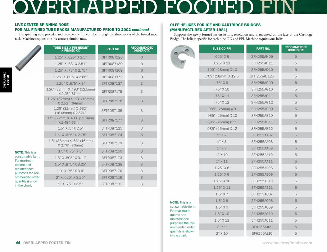
OVERLAPPED FOOTED FIN
www.mcelroyfintube.com
OVER
LAPP
EDFO
OTE
D
44 OVERLAPPED FOOTED FIN
LIVE CENTER SPINNING NOSEFOR ALL FINNED TUBE RACKS MANUFACTURED PRIOR TO 2002 continued
The spinning nose precedes and protects the finned tube through the three rollers of the finned tube rack. Machine requires one live center spinning nose.
TUBE SIZE X FIN HEIGHT X FINNED OD PART NO. RECOMMENDED
ORDER QTY.
1.25” X .625” X 2.5” 3FTR087126 3
1.25” X .63” X 2.51” 3FTR087180 3
1.25” X .75” X 2.75” 3FTR087109 3
1.25” X .805” X 2.86” 3FTR087172 3
1.25” X .875” X 3” 3FTR087137 31.26” (32mm) X .493” (12.5mm)
X 2.25” (57mm) 3FTR087176 3
1.26” (32mm) X .63” (16mm) X 2.52” (64mm) 3FTR087178 3
1.26” (32mm) X .632” (16.05mm) X 2.524” 3FTR087135 3
1.5” (38mm) X .493” (12.5mm) X 2.48” (63mm) 3FTR087177 3
1.5” X .5” X 2.5” 3FTR087125 3
1.5” X .625” X 2.75” 3FTR087124 3
1.5” (38mm) X .63” (16mm) X 2.76” (70mm) 3FTR087179 3
1.5” X .75” X 3” 3FTR087159 3
1.5” X .805” X 3.11” 3FTR087173 3
1.5” X .875” X 3.25” 3FTR087138 3
1.9” X .75” X 3.4” 3FTR087170 3
2” X .625” X 3.25” 3FTR087116 3
2” X .75” X 3.5” 3FTR087132 3
NOTE: This is a consumable item. For maximum uptime and maintenance purposes the rec-ommended order quantity is shown in the chart.
TUBE OD FPI PART NO. RECOMMENDED ORDER QTY.
.625” X 9 3FH255AH09 5
.625” X 11 3FH255AH11 5
.709” (18mm) X 10 3FH255AD10 5
.709” (18mm) X 12.5 3FH255AD125 5
.75” X 9 3FH255AG09 5
.75” X 10 3FH255AG10 5
.75” X 11 3FH255AG11 5
.75” X 12 3FH255AG12 5
.985” (25mm) X 9 3FH255AB09 5
.985” (25mm) X 10 3FH255AB10 5
.985” (25mm) X 11 3FH255AB11 5
.985” (25mm) X 12 3FH255AB12 5
1” X 7 3FH255AA07 5
1” X 8 3FH255AA08 5
1” X 9 3FH255AA09 5
1” X 10 3FH255AA10 5
1” X 11 3FH255AA11 5
1.25” X 6 3FH255AE06 5
1.25” X 9 3FH255AE09 5
1.25” X 10 3FH255AE10 5
1.25” X 11 3FH255AE11 5
1.5” X 7 3FH255AC07 5
1.5” X 8 3FH255AC08 5
1.5” X 9 3FH255AC09 5
1.5” X 10 3FH255AC10 5
1.5” X 11 3FH255AC11 5
2” X 9 3FH255AJ09 5
2” X 10 3FH255AJ10 5
OLFF HELIXES FOR ICF AND CARTRIDGE BRIDGES(MANUFACTURED AFTER 1981)
Supports the newly formed fin on its first revolution and is mounted on the face of the Cartridge Bridge. The helix is specific for each tube OD and FPI. Machine requires one helix.
NOTE: This is a consumable item. For maximum uptime and maintenance purposes the rec-ommended order quantity is shown in the chart.
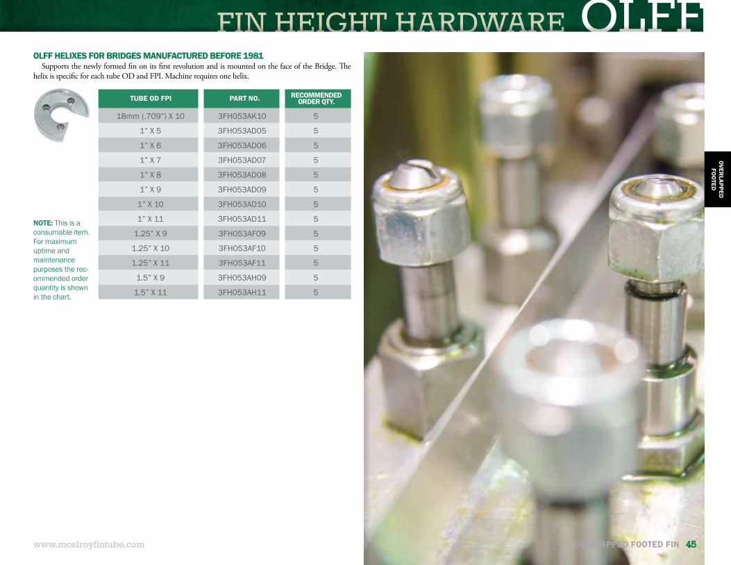
FIN HEIGHT HARDWARE OLFF
www.mcelroyfintube.com
OVERLAPPED
FOO
TED
OVERLAPPED FOOTED FIN 45
NOTE: This is a consumable item. For maximum uptime and maintenance purposes the rec-ommended order quantity is shown in the chart.
OLFF HELIXES FOR BRIDGES MANUFACTURED BEFORE 1981Supports the newly formed fin on its first revolution and is mounted on the face of the Bridge. The
helix is specific for each tube OD and FPI. Machine requires one helix.
TUBE OD FPI PART NO. RECOMMENDED ORDER QTY.
18mm (.709”) X 10 3FH053AK10 5
1” X 5 3FH053AD05 5
1” X 6 3FH053AD06 5
1” X 7 3FH053AD07 5
1” X 8 3FH053AD08 5
1” X 9 3FH053AD09 5
1” X 10 3FH053AD10 5
1” X 11 3FH053AD11 5
1.25” X 9 3FH053AF09 5
1.25” X 10 3FH053AF10 5
1.25” X 11 3FH053AF11 5
1.5” X 9 3FH053AH09 5
1.5” X 11 3FH053AH11 5
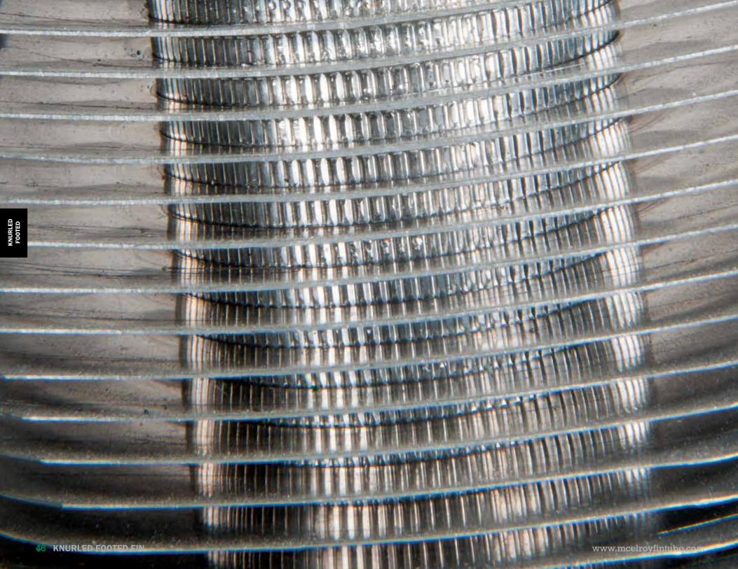
KNURLED FOOTED FIN KNURLED FOOTED FIN
www.mcelroyfintube.com
KN
UR
LED
FOO
TED
46 KNURLED FOOTED FIN
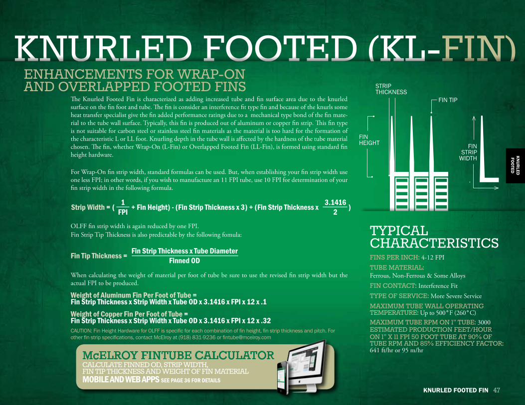
KNURLED FOOTED FIN KNURLED FOOTED FINKNURLED FOOTED (KL-FIN)
KN
UR
LEDFO
OTED
KNURLED FOOTED FIN 47
FINS PER INCH: 4-12 FPITUBE MATERIAL: Ferrous, Non-Ferrous & Some AlloysFIN CONTACT: Interference FitTYPE OF SERVICE: More Severe ServiceMAXIMUM TUBE WALL OPERATING TEMPERATURE: Up to 500°F (260°C) MAXIMUM TUBE RPM ON 1” TUBE: 3000ESTIMATED PRODUCTION FEET/HOUR ON 1” X 11 FPI 50 FOOT TUBE AT 90% OF TUBE RPM AND 85% EFFICIENCY FACTOR: 641 ft/hr or 95 m/hr
TYPICALCHARACTERISTICS
ENHANCEMENTS FOR WRAP-ON AND OVERLAPPED FOOTED FINS
FIN TIP
STRIP THICKNESS
The Knurled Footed Fin is characterized as adding increased tube and fin surface area due to the knurled surface on the fin foot and tube. The fin is consider an interference fit type fin and because of the knurls some heat transfer specialist give the fin added performance ratings due to a mechanical type bond of the fin mate-rial to the tube wall surface. Typically, this fin is produced out of aluminum or copper fin strip. This fin type is not suitable for carbon steel or stainless steel fin materials as the material is too hard for the formation of the characteristic L or LL foot. Knurling depth in the tube wall is affected by the hardness of the tube material chosen. The fin, whether Wrap-On (L-Fin) or Overlapped Footed Fin (LL-Fin), is formed using standard fin height hardware.
For Wrap-On fin strip width, standard formulas can be used. But, when establishing your fin strip width use one less FPI; in other words, if you wish to manufacture an 11 FPI tube, use 10 FPI for determination of your fin strip width in the following formula.
OLFF fin strip width is again reduced by one FPI. Fin Strip Tip Thickness is also predictable by the following fomula:
When calculating the weight of material per foot of tube be sure to use the revised fin strip width but the actual FPI to be produced.
Weight of Aluminum Fin Per Foot of Tube =Fin Strip Thickness x Strip Width x Tube OD x 3.1416 x FPI x 12 x .1 Weight of Copper Fin Per Foot of Tube =Fin Strip Thickness x Strip Width x Tube OD x 3.1416 x FPI x 12 x .32
Fin Tip Thickness = Fin Strip Thickness x Tube DiameterFinned OD
CAUTION: Fin Height Hardware for OLFF is specific for each combination of fin height, fin strip thickness and pitch. For other fin strip specifications, contact McElroy at (918) 831-9236 or [email protected]
Strip Width = ( + Fin Height) - (Fin Strip Thickness x 3) + (Fin Strip Thickness x )1FPI
3.14162
FIN STRIP
WIDTH
FIN HEIGHT
McELROY FINTUBE CALCULATOR CALCULATE FINNED OD, STRIP WIDTH,FIN TIP THICKNESS AND WEIGHT OF FIN MATERIALMOBILE AND WEB APPS SEE PAGE 36 FOR DETAILS
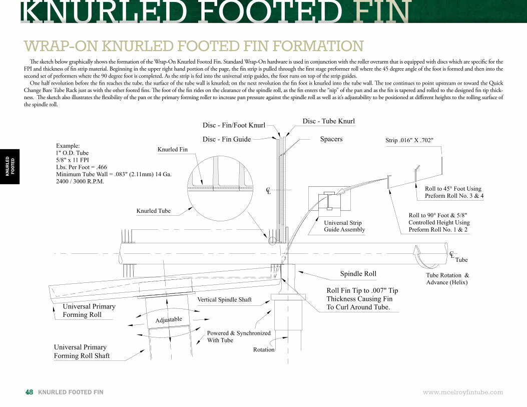
KNURLED FOOTED FIN KNURLED FOOTED FIN
Universal StripGuide Assembly
Roll to 90° Foot & 5/8"Controlled Height UsingPreform Roll No. 1 & 2
Roll to 45° Foot UsingPreform Roll No. 3 & 4
Strip .016" X .702"
Powered & SynchronizedWith Tube
Adjustable
Example:1" O.D. Tube5/8" x 11 FPILbs. Per Foot = .466Minimum Tube Wall = .083" (2.11mm) 14 Ga.2400 / 3000 R.P.M.
Spindle Roll
Roll Fin Tip to .007" TipThickness Causing FinTo Curl Around Tube.
Vertical Spindle Shaft
CLTube
Rotation
Disc - Tube KnurlDisc - Fin/Foot Knurl
Disc - Fin Guide Spacers
CL
Tube Rotation &Advance (Helix)
Knurled Tube
Knurled Fin
Universal PrimaryForming Roll Shaft
Universal Primary Forming Roll
www.mcelroyfintube.com
KN
UR
LED
FOO
TED
48 KNURLED FOOTED FIN
WRAP-ON KNURLED FOOTED FIN FORMATIONThe sketch below graphically shows the formation of the Wrap-On Knurled Footed Fin. Standard Wrap-On hardware is used in conjunction with the roller overarm that is equipped with discs which are specific for the
FPI and thickness of fin strip material. Beginning in the upper right hand portion of the page, the fin strip is pulled through the first stage preformer roll where the 45 degree angle of the foot is formed and then into the second set of preformers where the 90 degree foot is completed. As the strip is fed into the universal strip guides, the foot runs on top of the strip guides.
One half revolution before the fin reaches the tube, the surface of the tube wall is knurled; on the next revolution the fin foot is knurled into the tube wall. The toe continues to point upstream or toward the Quick Change Bare Tube Rack just as with the other footed fins. The foot of the fin rides on the clearance of the spindle roll, as the fin enters the “nip” of the pan and as the fin is tapered and rolled to the designed fin tip thick-ness. The sketch also illustrates the flexibility of the pan or the primary forming roller to increase pan pressure against the spindle roll as well as it’s adjustability to be positioned at different heights to the rolling surface of the spindle roll.
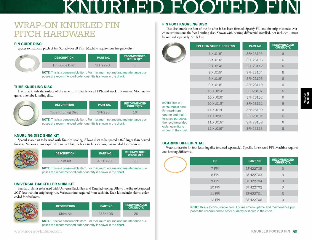
KNURLED FOOTED FIN KNURLED FOOTED FIN
www.mcelroyfintube.com
KN
UR
LEDFO
OTED
KNURLED FOOTED FIN 49
WRAP-ON KNURLED FINPITCH HARDWARE
DESCRIPTION PART NO. RECOMMENDED ORDER QTY.
Fin Guide Disc 3FH229B 3
FPI X FIN STRIP THICKNESS PART NO. RECOMMENDED ORDER QTY.
7 X .016” 3FH23105 6
8 X .016” 3FH23103 6
9 X .014” 3FH23112 6
9 X .015” 3FH23104 6
9 X .016” 3FH23106 6
9 X .018” 3FH23110 6
10 X .014” 3FH23107 6
10 X .016” 3FH23102 6
10 X .018” 3FH23111 6
11 X .014” 3FH23109 6
11 X .016” 3FH23101 6
11 X .018” 3FH23108 6
12 X .016” 3FH23113 6
DESCRIPTION PART NO. RECOMMENDED ORDER QTY.
Tube Knurling Disc 3FH230 16
DESCRIPTION PART NO. RECOMMENDED ORDER QTY.
Shim Kit A3FH429 20 FPI PART NO. RECOMMENDED ORDER QTY.
7 FPI 3FH22705 3
8 FPI 3FH22703 3
9 FPI 3FH22704 3
10 FPI 3FH22702 3
11 FPI 3FH22701 3
12 FPI 3FH22706 3
DESCRIPTION PART NO. RECOMMENDED ORDER QTY.
Shim Kit A3FH403 20
FIN GUIDE DISCSpacer to maintain pitch of fin. Suitable for all FPIs. Machine requires one fin guide disc.
NOTE: This is a consumable item. For maximum uptime and maintenance pur-poses the recommended order quantity is shown in the chart.
NOTE: This is a consumable item. For maximum uptime and main-tenance purposes the recommended order quantity is shown in the chart.
NOTE: This is a consumable item. For maximum uptime and maintenance pur-poses the recommended order quantity is shown in the chart.
NOTE: This is a consumable item. For maximum uptime and maintenance pur-poses the recommended order quantity is shown in the chart.
NOTE: This is a consumable item. For maximum uptime and maintenance pur-poses the recommended order quantity is shown in the chart.
NOTE: This is a consumable item. For maximum uptime and maintenance pur-poses the recommended order quantity is shown in the chart.
TUBE KNURLING DISCDisc that knurls the surface of the tube. It is suitable for all FPIs and stock thicknesses. Machine re-
quires one tube knurling disc.
KNURLING DISC SHIM KITSpecial spacer kit to be used with Knurled tooling. Allows discs to be spaced .002” larger than desired
fin strip. Various shims required from each kit. Each kit includes shims, color-coded for thickness.
UNIVERSAL BACKFILLER SHIM KITStandard shims to be used with Universal Backfillers and Knurled tooling. Allows the disc to be spaced
.002” less than fin strip being run. Various shims required from each kit. Each kit includes shims, color-coded for thickness.
FIN FOOT KNURLING DISCThis disc knurls the foot of the fin after it has been formed. Specify FPI and fin strip thickness. Ma-
chine requires one fin foot knurling disc. Shown with bearing differential installed, not included - must be ordered separately. See below.
BEARING DIFFERENTIALWear surface for fin foot knurling disc (ordered separately). Specific for selected FPI. Machine requires
one bearing differential.
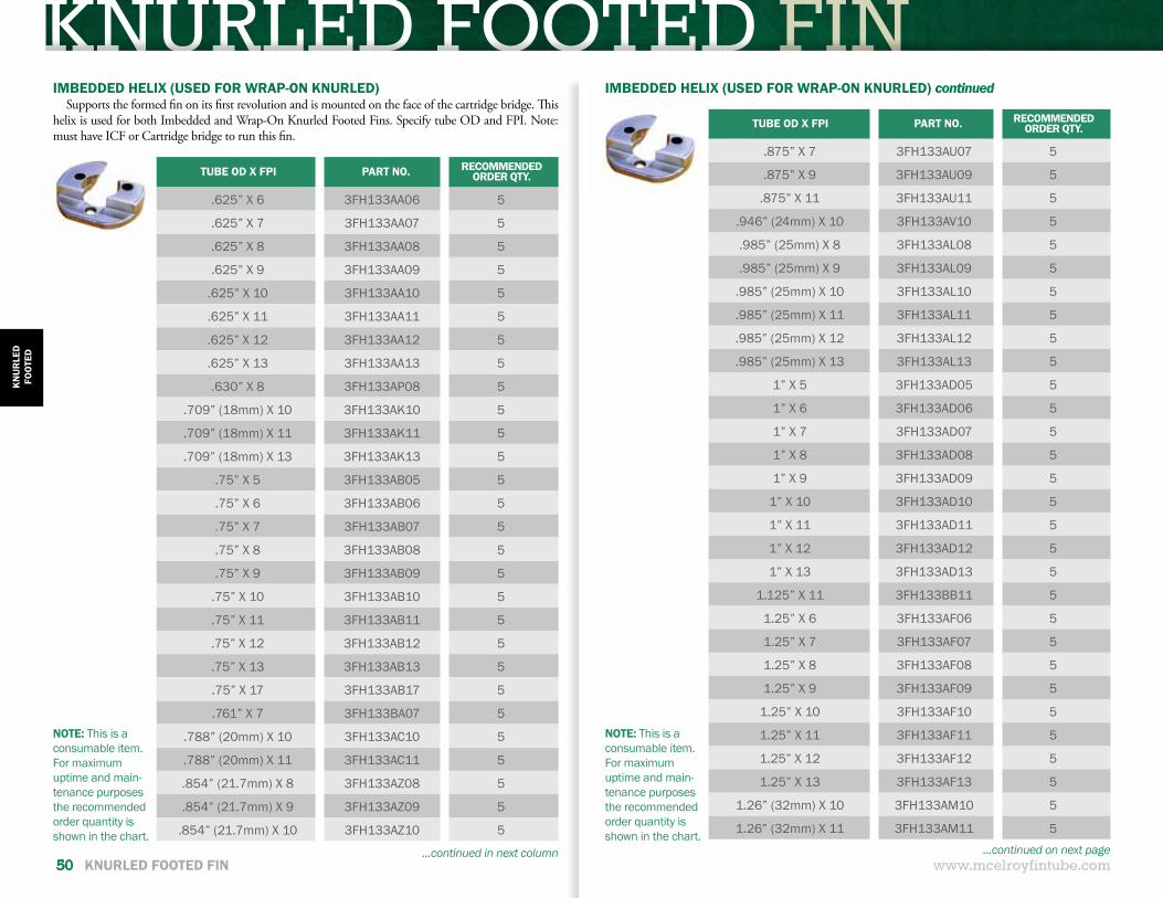
KNURLED FOOTED FIN KNURLED FOOTED FIN
www.mcelroyfintube.com
KN
UR
LED
FOO
TED
50 KNURLED FOOTED FIN
NOTE: This is a consumable item. For maximum uptime and main-tenance purposes the recommended order quantity is shown in the chart.
NOTE: This is a consumable item. For maximum uptime and main-tenance purposes the recommended order quantity is shown in the chart.
IMBEDDED HELIX (USED FOR WRAP-ON KNURLED)Supports the formed fin on its first revolution and is mounted on the face of the cartridge bridge. This
helix is used for both Imbedded and Wrap-On Knurled Footed Fins. Specify tube OD and FPI. Note: must have ICF or Cartridge bridge to run this fin.
IMBEDDED HELIX (USED FOR WRAP-ON KNURLED) continued
TUBE OD X FPI PART NO. RECOMMENDED ORDER QTY.
.625” X 6 3FH133AA06 5
.625” X 7 3FH133AA07 5
.625” X 8 3FH133AA08 5
.625” X 9 3FH133AA09 5
.625” X 10 3FH133AA10 5
.625” X 11 3FH133AA11 5
.625” X 12 3FH133AA12 5
.625” X 13 3FH133AA13 5
.630” X 8 3FH133AP08 5
.709” (18mm) X 10 3FH133AK10 5
.709” (18mm) X 11 3FH133AK11 5
.709” (18mm) X 13 3FH133AK13 5
.75” X 5 3FH133AB05 5
.75” X 6 3FH133AB06 5
.75” X 7 3FH133AB07 5
.75” X 8 3FH133AB08 5
.75” X 9 3FH133AB09 5
.75” X 10 3FH133AB10 5
.75” X 11 3FH133AB11 5
.75” X 12 3FH133AB12 5
.75” X 13 3FH133AB13 5
.75” X 17 3FH133AB17 5
.761” X 7 3FH133BA07 5
.788” (20mm) X 10 3FH133AC10 5
.788” (20mm) X 11 3FH133AC11 5
.854” (21.7mm) X 8 3FH133AZ08 5
.854” (21.7mm) X 9 3FH133AZ09 5
.854” (21.7mm) X 10 3FH133AZ10 5
TUBE OD X FPI PART NO. RECOMMENDED ORDER QTY.
.875” X 7 3FH133AU07 5
.875” X 9 3FH133AU09 5
.875” X 11 3FH133AU11 5
.946” (24mm) X 10 3FH133AV10 5
.985” (25mm) X 8 3FH133AL08 5
.985” (25mm) X 9 3FH133AL09 5
.985” (25mm) X 10 3FH133AL10 5
.985” (25mm) X 11 3FH133AL11 5
.985” (25mm) X 12 3FH133AL12 5
.985” (25mm) X 13 3FH133AL13 5
1” X 5 3FH133AD05 5
1” X 6 3FH133AD06 5
1” X 7 3FH133AD07 5
1” X 8 3FH133AD08 5
1” X 9 3FH133AD09 5
1” X 10 3FH133AD10 5
1” X 11 3FH133AD11 5
1” X 12 3FH133AD12 5
1” X 13 3FH133AD13 5
1.125” X 11 3FH133BB11 5
1.25” X 6 3FH133AF06 5
1.25” X 7 3FH133AF07 5
1.25” X 8 3FH133AF08 5
1.25” X 9 3FH133AF09 5
1.25” X 10 3FH133AF10 5
1.25” X 11 3FH133AF11 5
1.25” X 12 3FH133AF12 5
1.25” X 13 3FH133AF13 5
1.26” (32mm) X 10 3FH133AM10 5
1.26” (32mm) X 11 3FH133AM11 5
...continued in next column ...continued on next page
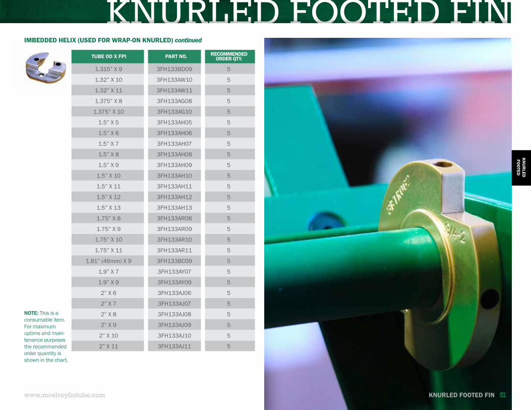
KNURLED FOOTED FIN KNURLED FOOTED FIN
www.mcelroyfintube.com
KN
UR
LEDFO
OTED
KNURLED FOOTED FIN 51
NOTE: This is a consumable item. For maximum uptime and main-tenance purposes the recommended order quantity is shown in the chart.
IMBEDDED HELIX (USED FOR WRAP-ON KNURLED) continued
TUBE OD X FPI PART NO. RECOMMENDED ORDER QTY.
1.315” X 9 3FH133BD09 5
1.32” X 10 3FH133AW10 5
1.32” X 11 3FH133AW11 5
1.375” X 8 3FH133AG08 5
1.375” X 10 3FH133AG10 5
1.5” X 5 3FH133AH05 5
1.5” X 6 3FH133AH06 5
1.5” X 7 3FH133AH07 5
1.5” X 8 3FH133AH08 5
1.5” X 9 3FH133AH09 5
1.5” X 10 3FH133AH10 5
1.5” X 11 3FH133AH11 5
1.5” X 12 3FH133AH12 5
1.5” X 13 3FH133AH13 5
1.75” X 8 3FH133AR08 5
1.75” X 9 3FH133AR09 5
1.75” X 10 3FH133AR10 5
1.75” X 11 3FH133AR11 5
1.81” (46mm) X 9 3FH133BC09 5
1.9” X 7 3FH133AY07 5
1.9” X 9 3FH133AY09 5
2” X 6 3FH133AJ06 5
2” X 7 3FH133AJ07 5
2” X 8 3FH133AJ08 5
2” X 9 3FH133AJ09 5
2” X 10 3FH133AJ10 5
2” X 11 3FH133AJ11 5
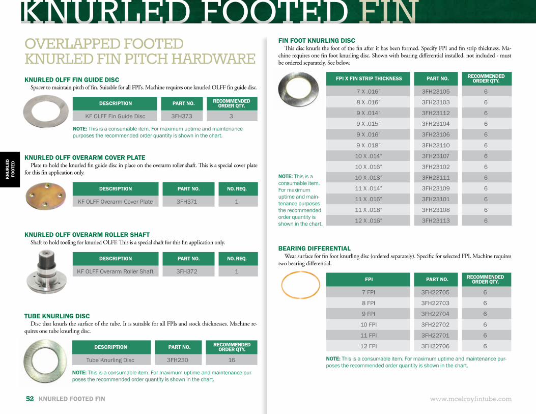
KNURLED FOOTED FIN KNURLED FOOTED FIN
www.mcelroyfintube.com
KN
UR
LED
FOO
TED
52 KNURLED FOOTED FIN
FPI X FIN STRIP THICKNESS PART NO. RECOMMENDED ORDER QTY.
7 X .016” 3FH23105 6
8 X .016” 3FH23103 6
9 X .014” 3FH23112 6
9 X .015” 3FH23104 6
9 X .016” 3FH23106 6
9 X .018” 3FH23110 6
10 X .014” 3FH23107 6
10 X .016” 3FH23102 6
10 X .018” 3FH23111 6
11 X .014” 3FH23109 6
11 X .016” 3FH23101 6
11 X .018” 3FH23108 6
12 X .016” 3FH23113 6
NOTE: This is a consumable item. For maximum uptime and main-tenance purposes the recommended order quantity is shown in the chart.
FIN FOOT KNURLING DISCThis disc knurls the foot of the fin after it has been formed. Specify FPI and fin strip thickness. Ma-
chine requires one fin foot knurling disc. Shown with bearing differential installed, not included - must be ordered separately. See below.
FPI PART NO. RECOMMENDED ORDER QTY.
7 FPI 3FH22705 6
8 FPI 3FH22703 6
9 FPI 3FH22704 6
10 FPI 3FH22702 6
11 FPI 3FH22701 6
12 FPI 3FH22706 6
NOTE: This is a consumable item. For maximum uptime and maintenance pur-poses the recommended order quantity is shown in the chart.
BEARING DIFFERENTIALWear surface for fin foot knurling disc (ordered separately). Specific for selected FPI. Machine requires
two bearing differential.
NOTE: This is a consumable item. For maximum uptime and maintenance purposes the recommended order quantity is shown in the chart.
DESCRIPTION PART NO. RECOMMENDED ORDER QTY.
KF OLFF Fin Guide Disc 3FH373 3
DESCRIPTION PART NO. NO. REQ.
KF OLFF Overarm Cover Plate 3FH371 1
DESCRIPTION PART NO. NO. REQ.
KF OLFF Overarm Roller Shaft 3FH372 1
KNURLED OLFF FIN GUIDE DISCSpacer to maintain pitch of fin. Suitable for all FPI’s. Machine requires one knurled OLFF fin guide disc.
KNURLED OLFF OVERARM COVER PLATEPlate to hold the knurled fin guide disc in place on the overarm roller shaft. This is a special cover plate
for this fin application only.
KNURLED OLFF OVERARM ROLLER SHAFTShaft to hold tooling for knurled OLFF. This is a special shaft for this fin application only.
OVERLAPPED FOOTEDKNURLED FIN PITCH HARDWARE
DESCRIPTION PART NO. RECOMMENDED ORDER QTY.
Tube Knurling Disc 3FH230 16
NOTE: This is a consumable item. For maximum uptime and maintenance pur-poses the recommended order quantity is shown in the chart.
TUBE KNURLING DISCDisc that knurls the surface of the tube. It is suitable for all FPIs and stock thicknesses. Machine re-
quires one tube knurling disc.
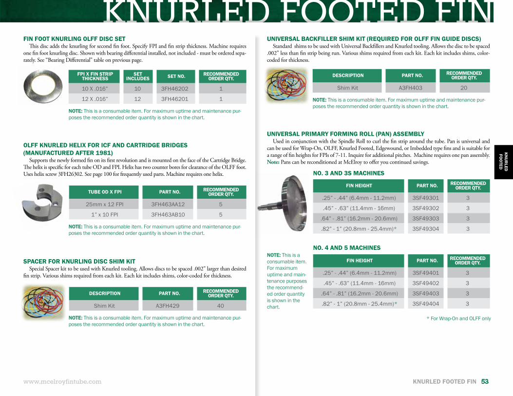
KNURLED FOOTED FIN KNURLED FOOTED FIN
www.mcelroyfintube.com
KN
UR
LEDFO
OTED
KNURLED FOOTED FIN 53
NOTE: This is a consumable item. For maximum uptime and maintenance pur-poses the recommended order quantity is shown in the chart.
NOTE: This is a consumable item. For maximum uptime and maintenance pur-poses the recommended order quantity is shown in the chart.
NOTE: This is a consumable item. For maximum uptime and maintenance pur-poses the recommended order quantity is shown in the chart.
FIN FOOT KNURLING OLFF DISC SETThis disc adds the knurling for second fin foot. Specify FPI and fin strip thickness. Machine requires
one fin foot knurling disc. Shown with bearing differential installed, not included - must be ordered sepa-rately. See “Bearing Differential” table on previous page.
TUBE OD X FPI PART NO. RECOMMENDED ORDER QTY.
25mm x 12 FPI 3FH463AA12 5
1” x 10 FPI 3FH463AB10 5
DESCRIPTION PART NO. RECOMMENDED ORDER QTY.
Shim Kit A3FH429 40
OLFF KNURLED HELIX FOR ICF AND CARTRIDGE BRIDGES(MANUFACTURED AFTER 1981)
Supports the newly formed fin on its first revolution and is mounted on the face of the Cartridge Bridge. The helix is specific for each tube OD and FPI. Helix has two counter bores for clearance of the OLFF foot. Uses helix screw 3FH26302. See page 100 for frequently used parts. Machine requires one helix.
FPI X FIN STRIP THICKNESS
SET INCLUDES SET NO. RECOMMENDED
ORDER QTY.
10 X .016” 10 3FH46202 1
12 X .016” 12 3FH46201 1
SPACER FOR KNURLING DISC SHIM KITSpecial Spacer kit to be used with Knurled tooling. Allows discs to be spaced .002” larger than desired
fin strip. Various shims required from each kit. Each kit includes shims, color-coded for thickness.
DESCRIPTION PART NO. RECOMMENDED ORDER QTY.
Shim Kit A3FH403 20
NOTE: This is a consumable item. For maximum uptime and maintenance pur-poses the recommended order quantity is shown in the chart.
UNIVERSAL BACKFILLER SHIM KIT (REQUIRED FOR OLFF FIN GUIDE DISCS)Standard shims to be used with Universal Backfillers and Knurled tooling. Allows the disc to be spaced
.002” less than fin strip being run. Various shims required from each kit. Each kit includes shims, color-coded for thickness.
NOTE: This is a consumable item. For maximum uptime and main-tenance purposes the recommend-ed order quantity is shown in the chart.
FIN HEIGHT PART NO. RECOMMENDED ORDER QTY.
.25” - .44” (6.4mm - 11.2mm) 3SF49301 3
.45” - .63” (11.4mm - 16mm) 3SF49302 3
.64” - .81” (16.2mm - 20.6mm) 3SF49303 3
.82” - 1” (20.8mm - 25.4mm)* 3SF49304 3
FIN HEIGHT PART NO. RECOMMENDED ORDER QTY.
.25” - .44” (6.4mm - 11.2mm) 3SF49401 3
.45” - .63” (11.4mm - 16mm) 3SF49402 3
.64” - .81” (16.2mm - 20.6mm) 3SF49403 3
.82” - 1” (20.8mm - 25.4mm)* 3SF49404 3
UNIVERSAL PRIMARY FORMING ROLL (PAN) ASSEMBLYUsed in conjunction with the Spindle Roll to curl the fin strip around the tube. Pan is universal and
can be used for Wrap-On, OLFF, Knurled Footed, Edgewound, or Imbedded type fins and is suitable for a range of fin heights for FPIs of 7-11. Inquire for additional pitches. Machine requires one pan assembly. Note: Pans can be reconditioned at McElroy to offer you continued savings.
NO. 3 AND 3S MACHINES
NO. 4 AND 5 MACHINES
* For Wrap-On and OLFF only
IMBEDDED FIN
www.mcelroyfintube.com
IMB
EDD
ED
54 IMBEDDED FIN
IMBEDDED FINIMBEDDED
FIN TIP
STRIP THICKNESS
FIN STRIP WIDTH
(G-FIN)
IMB
EDD
ED
IMBEDDED FIN 55
FINS PER INCH: 5-13 FPITUBE MATERIAL: Ferrous, Non-Ferrous & Some AlloysFIN CONTACT: Mechanical BondTYPE OF SERVICE: High TemperatureMAXIMUM TUBE WALL OPERATING TEMPERATURE: Based on fin material: Aluminum: 650°F (343°C); Carbon Steel 850°F (450°C); Stainless Steel 1000°F (540°C)MAXIMUM TUBE RPM ON 1” TUBE: 3000ESTIMATED PRODUCTION FEET/HOUR ON 1” TUBE AT 11 FPI AT 90% OF TUBE RPM AND 85% EFFICIENCY FACTOR: 512 ft/hr or 156 m/hr
TYPICALCHARACTERISTICS
The Imbedded Fin, also known as a G-fin (grooved fin), is widely used throughout the world. This fin is considered to have a mechanical bond to the tube and has negligible deterioration of the fin bond with heat cycling. The fin is usually specified for high temperature applications with the fin material being the limiting factor. Typically, this fin is produced out of aluminum or copper fin strip. This fin type is also suitable for carbon steel or stainless steel fin materials, but requires special tooling and processing of these steel fin strips.
Preforming is not required for aluminum fin on carbon steel tubes, but is required for copper or steel fin and in the case of aluminum fin on aluminum tubes. Dovetail rollers are used to preform the fin and facilitates insertion into the groove. When standard groove depth is used for aluminum or copper fin strip, the fin strip width is always .012” larger than the fin height, i.e. .625” plus .012” = .637”.
Fin Strip Tip Thickness is also predictable by the following formula:
Fin Tip Thickness = Fin Strip Thickness x Tube DiameterFinned OD
The imbedding process is controlled by the plow and backfillers which are mounted on a bearing overarm and positioned to form a groove one-half pitch upstream of the forming of the fin by the pan and spindle roll. This positions an open groove for the fin as it is curled. The fin is loosely curled into the groove until it completes another half revolution. The backfillers roll in each side of the groove to form a lock of the fin to the tube wall. The relative position of the plow and backfillers are locked together on one tool and do not need to be adjusted by the operator.
FIN HEIGHT
Weight of Aluminum Fin Per Foot of Tube = Fin Strip Thickness x Fin Strip Width x Tube OD x 3.1416 x FPI x 12 x .1
Weight of Copper Fin Per Foot of Tube = Fin Strip Thickness x Fin Strip Width x Tube OD x 3.1416 x FPI x 12 x .32Note: If you have special requirements or need assistance, contact (918) 831-9236 or [email protected]
McELROY FINTUBE CALCULATOR CALCULATE FINNED OD, STRIP WIDTH,FIN TIP THICKNESS AND WEIGHT OF FIN MATERIALMOBILE AND WEB APPS SEE PAGE 36 FOR DETAILS
IMBEDDED FIN
Universal StripGuide Assembly
Optional:Dovetail PreformerFor Steel, Copper, OrAluminum Fin on AluminumTube
Strip .016" X .637"
Powered & SynchronizedWith Tube
McElroyImbedded (G) FinsPlow Tools
Spindle Roll
Roll Fin Tip to .007" TipThickness Causing FinTo Curl Around Tube.
Vertical Spindle Shaft
Universal PrimaryForming Roll Shaft
Universal PrimaryForming Roll
CLTube
Rotation
.012"Helix
Plow Groover(Stationary)Backfiller
(Rolling)
Spacer
Exhibit D
FIN
CL
Example:1" O.D. C.S. Tube5/8" x 11 FPIMinimum Tube Wall = .083" (S.S.)Maximum Hardness RcB 74/90Alum. Fin - Lbs. Per Ft. = .4231200/3000 R.P.M. Maximum for C.S.Shell Pull Test > 25 Lbs.
Tube
Adjustable
www.mcelroyfintube.com
IMB
EDD
ED
56 IMBEDDED FIN
IMBEDDED FIN FORMATIONThe sketch below graphically shows the formation of the Imbedded Fin. Preforming of the fin strip is not required for aluminum fin material. Dovetail rollers are required in the case of carbon steel, stainless steel fin,
copper fin on copper tubes, or aluminum fin on aluminum tubes. The strip is led from the lead in roller frame into the universal strip guides.The imbedding process is controlled by the plow and backfillers which are mounted on a bearing overarm and positioned to form a groove one-half pitch upstream of the forming of the fin by the pan and spindle roll.
This positions an open groove for the fin as it is curled. The groove material raised by the plow is much like the furrow of a farmer’s plow. The fin is loosely curled into the groove until it completes another half revolution. The backfillers roll in the sides of the groove to form a lock of the fin into the tube wall. The relative position of the plow and backfillers are locked together on one tool and do not need to be adjusted by the operator.
IMBEDDED FINDESCRIPTION PART NO. RECOMMENDED
ORDER QTY.
Universal Strip Guide Clamp 3SF509 1
STRIP GUIDE CLAMPSOne Universal Strip Guide Clamp is required to secure the strip guide set in place. The same clamp
can be used on all Universal Strip Guides. Machine requires one clamp.
CARBIDE FOR UNIVERSAL STRIP GUIDE CLAMPCarbide wears separately from the Universal Strip Guide Clamp and
can be replaced independently. Part No. 3SF50902
www.mcelroyfintube.com
IMB
EDD
ED
IMBEDDED FIN 57
UNIVERSAL STRIP GUIDE SETFor strip thickness from .014” (.355mm) to .020” (.508mm)
A guide to position the strip between the Pan and Spindle Roll. Universal strip guides will accept strip thicknesses from .014” (.355mm) to .020” (.508mm) and will accept fi n heights as indicated in part de-scription. Requires Universal Strip Guide Clamp 3SF09. Machine requires one Strip Guide Set.
FIN HEIGHT SET NO. RECOMMENDEDORDER QTY.
.25” - .44” (.64 - 11.2mm) 3SF510 2
.45” - .63” (11.4 - 16mm) 3SF511 2
.64” - .81” (16.2 - 20.6mm) 3SF512 2
.82” - 1.0” (20.8 - 25.4mm) 3SF513 2
FIN HEIGHT PART NO. RECOMMENDED ORDER QTY.
.25” - .35” (6.4mm - 9mm) 3SF49101 8
.36” - .44” (9.1mm - 11.2mm) 3SF49102 8
.45” - .53” (11.4mm - 13.5mm) 3SF49103 8
.54” - .63” (13.7mm - 16mm) 3SF49104 8
.64” - .81” (16.2mm - 20.6mm) 3SF49105 8
UNIVERSAL SPINDLE ROLL (IMBEDDED, G-FIN)Used in conjunction with the Pan to curl the fin strip around the tube. Spindle roll is specific for the
type of fin and is suitable for a range of fin heights. Machine requires one spindle roll.
NOTE: This is a consumable item. For maximum uptime and maintenance pur-poses the recommended order quantity is shown in the chart.
NOTE: This is a consumable item. For maximum uptime and main-tenance purposes the recommend-ed order quantity is shown in the chart.
FIN HEIGHT PART NO. RECOMMENDED ORDER QTY.
.25” - .44”(6.4mm - 11.2mm) 3SF49301 3
.45” - .63”(11.4mm - 16mm) 3SF49302 3
.64” - .81”(16.2mm - 20.6mm) 3SF49303 3
.82” - 1”(20.8mm - 25.4mm)* 3SF49304 3
FIN HEIGHT PART NO. RECOMMENDED ORDER QTY.
.25” - .44”(6.4mm - 11.2mm) 3SF49401 3
.45” - .63”(11.4mm - 16mm) 3SF49402 3
.64” - .81”(16.2mm - 20.6mm) 3SF49403 3
.82” - 1”(20.8mm - 25.4mm)* 3SF49404 3
NO. 3 AND 3S MACHINES
NO. 4 AND 5 MACHINES
* For Wrap-On and OLFF only
UNIVERSAL PRIMARY FORMING ROLL (PAN) ASSEMBLYUsed in conjunction with the Spindle Roll to curl the fin strip around the tube. Pan is universal and
can be used for Wrap-On, OLFF, Knurled Footed, Edgewound, or Imbedded type fins and is suitable for a range of fin heights for FPIs of 7-11. Inquire for additional pitches. Machine requires one pan assembly. Note: Pans can be reconditioned at McElroy to offer you continued savings.
NOTE: This is a consumable item. For maximum uptime and maintenance purposes the recommended order quantity is shown in the chart.
UNIVERSAL STRIP GUIDE SETFor strip thickness less than .014” (.355mm)A guide to position the strip between the Pan and Spindle Roll. Universal strip guides will accept strip thicknesses of less than .014” (.355mm) and will accept fin heights as indicated in part description. Ma-chine requires one strip guide set.
FIN HEIGHT SET NO. RECOMMENDED ORDER QTY.
.25” - .44” (6.4 - 11.2mm) 3SF544 2
.45” - .63” (11.4 - 16mm) 3SF545 2
.64” - .81” (16.2 - 20.6mm) 3SF546 2
.82” - 1.0” (20.8 - 25.4mm) 3SF547 2
NOTE: This is a consumable item. For maximum uptime and maintenance pur-poses the recommended order quantity is shown in the chart.
NOTE: Sole plate type strip guides require a different clamp.
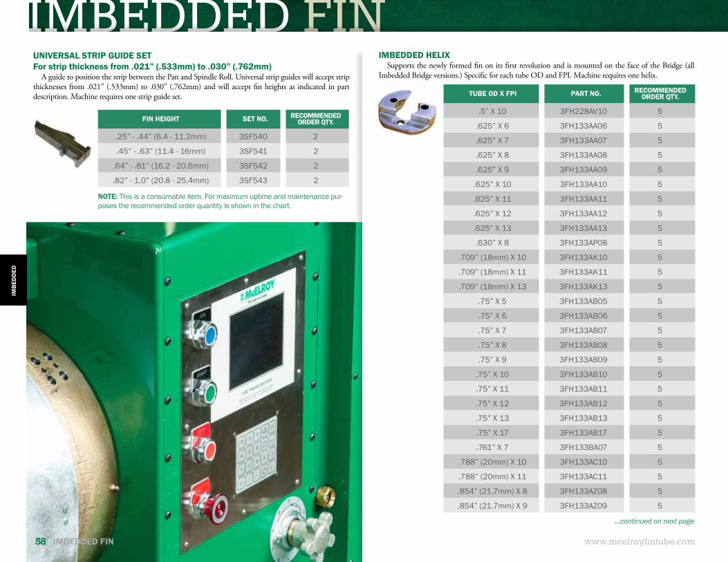
IMBEDDED FIN
www.mcelroyfintube.com
IMB
EDD
ED
58 IMBEDDED FIN
TUBE OD X FPI PART NO. RECOMMENDED ORDER QTY.
.5” X 10 3FH228AV10 5
.625” X 6 3FH133AA06 5
.625” X 7 3FH133AA07 5
.625” X 8 3FH133AA08 5
.625” X 9 3FH133AA09 5
.625” X 10 3FH133AA10 5
.625” X 11 3FH133AA11 5
.625” X 12 3FH133AA12 5
.625” X 13 3FH133AA13 5
.630” X 8 3FH133AP08 5
.709” (18mm) X 10 3FH133AK10 5
.709” (18mm) X 11 3FH133AK11 5
.709” (18mm) X 13 3FH133AK13 5
.75” X 5 3FH133AB05 5
.75” X 6 3FH133AB06 5
.75” X 7 3FH133AB07 5
.75” X 8 3FH133AB08 5
.75” X 9 3FH133AB09 5
.75” X 10 3FH133AB10 5
.75” X 11 3FH133AB11 5
.75” X 12 3FH133AB12 5
.75” X 13 3FH133AB13 5
.75” X 17 3FH133AB17 5
.761” X 7 3FH133BA07 5
.788” (20mm) X 10 3FH133AC10 5
.788” (20mm) X 11 3FH133AC11 5
.854” (21.7mm) X 8 3FH133AZ08 5
.854” (21.7mm) X 9 3FH133AZ09 5
IMBEDDED HELIXSupports the newly formed fin on its first revolution and is mounted on the face of the Bridge (all
Imbedded Bridge versions.) Specific for each tube OD and FPI. Machine requires one helix.
...continued on next page
UNIVERSAL STRIP GUIDE SETFor strip thickness from .021” (.533mm) to .030” (.762mm)
A guide to position the strip between the Pan and Spindle Roll. Universal strip guides will accept strip thicknesses from .021” (.533mm) to .030” (.762mm) and will accept fin heights as indicated in part description. Machine requires one strip guide set.
FIN HEIGHT SET NO. RECOMMENDED ORDER QTY.
.25” - .44” (6.4 - 11.2mm) 3SF540 2
.45” - .63” (11.4 - 16mm) 3SF541 2
.64” - .81” (16.2 - 20.6mm) 3SF542 2
.82” - 1.0” (20.8 - 25.4mm) 3SF543 2
NOTE: This is a consumable item. For maximum uptime and maintenance pur-poses the recommended order quantity is shown in the chart.
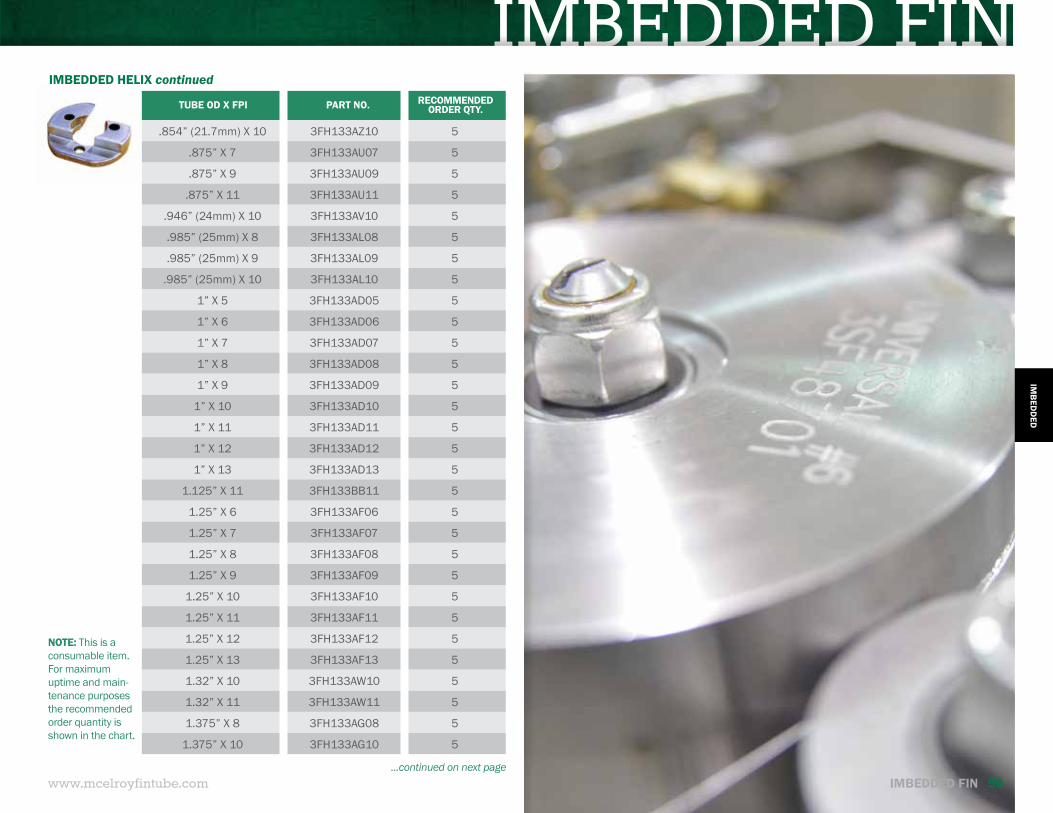
IMBEDDED FIN
www.mcelroyfintube.com
IMB
EDD
ED
IMBEDDED FIN 59...continued on next page
IMBEDDED HELIX continued
TUBE OD X FPI PART NO. RECOMMENDED ORDER QTY.
.854” (21.7mm) X 10 3FH133AZ10 5
.875” X 7 3FH133AU07 5
.875” X 9 3FH133AU09 5
.875” X 11 3FH133AU11 5
.946” (24mm) X 10 3FH133AV10 5
.985” (25mm) X 8 3FH133AL08 5
.985” (25mm) X 9 3FH133AL09 5
.985” (25mm) X 10 3FH133AL10 5
1” X 5 3FH133AD05 5
1” X 6 3FH133AD06 5
1” X 7 3FH133AD07 5
1” X 8 3FH133AD08 5
1” X 9 3FH133AD09 5
1” X 10 3FH133AD10 5
1” X 11 3FH133AD11 5
1” X 12 3FH133AD12 5
1” X 13 3FH133AD13 5
1.125” X 11 3FH133BB11 5
1.25” X 6 3FH133AF06 5
1.25” X 7 3FH133AF07 5
1.25” X 8 3FH133AF08 5
1.25” X 9 3FH133AF09 5
1.25” X 10 3FH133AF10 5
1.25” X 11 3FH133AF11 5
1.25” X 12 3FH133AF12 5
1.25” X 13 3FH133AF13 5
1.32” X 10 3FH133AW10 5
1.32” X 11 3FH133AW11 5
1.375” X 8 3FH133AG08 5
1.375” X 10 3FH133AG10 5
NOTE: This is a consumable item. For maximum uptime and main-tenance purposes the recommended order quantity is shown in the chart.
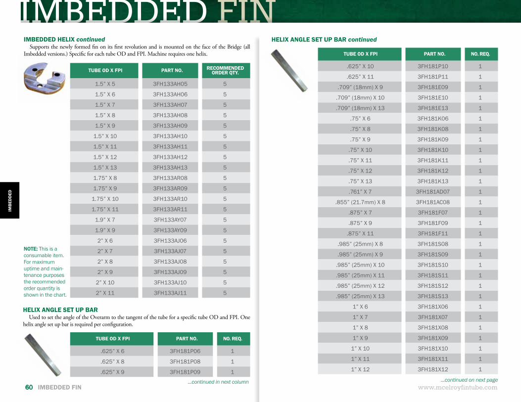
IMBEDDED FIN
www.mcelroyfintube.com
IMB
EDD
ED
60 IMBEDDED FIN
TUBE OD X FPI PART NO. RECOMMENDED ORDER QTY.
1.5” X 5 3FH133AH05 5
1.5” X 6 3FH133AH06 5
1.5” X 7 3FH133AH07 5
1.5” X 8 3FH133AH08 5
1.5” X 9 3FH133AH09 5
1.5” X 10 3FH133AH10 5
1.5” X 11 3FH133AH11 5
1.5” X 12 3FH133AH12 5
1.5” X 13 3FH133AH13 5
1.75” X 8 3FH133AR08 5
1.75” X 9 3FH133AR09 5
1.75” X 10 3FH133AR10 5
1.75” X 11 3FH133AR11 5
1.9” X 7 3FH133AY07 5
1.9” X 9 3FH133AY09 5
2” X 6 3FH133AJ06 5
2” X 7 3FH133AJ07 5
2” X 8 3FH133AJ08 5
2” X 9 3FH133AJ09 5
2” X 10 3FH133AJ10 5
2” X 11 3FH133AJ11 5
IMBEDDED HELIX continuedSupports the newly formed fin on its first revolution and is mounted on the face of the Bridge (all
Imbedded versions.) Specific for each tube OD and FPI. Machine requires one helix.
TUBE OD X FPI PART NO. NO. REQ.
.625” X 6 3FH181P06 1
.625” X 8 3FH181P08 1
.625” X 9 3FH181P09 1...continued on next page...continued in next column
NOTE: This is a consumable item. For maximum uptime and main-tenance purposes the recommended order quantity is shown in the chart.
HELIX ANGLE SET UP BARUsed to set the angle of the Overarm to the tangent of the tube for a specific tube OD and FPI. One
helix angle set up bar is required per configuration.
HELIX ANGLE SET UP BAR continued
TUBE OD X FPI PART NO. NO. REQ.
.625” X 10 3FH181P10 1
.625” X 11 3FH181P11 1
.709” (18mm) X 9 3FH181E09 1
.709” (18mm) X 10 3FH181E10 1
.709” (18mm) X 13 3FH181E13 1
.75” X 6 3FH181K06 1
.75” X 8 3FH181K08 1
.75” X 9 3FH181K09 1
.75” X 10 3FH181K10 1
.75” X 11 3FH181K11 1
.75” X 12 3FH181K12 1
.75” X 13 3FH181K13 1
.761” X 7 3FH181AD07 1
.855” (21.7mm) X 8 3FH181AC08 1
.875” X 7 3FH181F07 1
.875” X 9 3FH181F09 1
.875” X 11 3FH181F11 1
.985” (25mm) X 8 3FH181S08 1
.985” (25mm) X 9 3FH181S09 1
.985” (25mm) X 10 3FH181S10 1
.985” (25mm) X 11 3FH181S11 1
.985” (25mm) X 12 3FH181S12 1
.985” (25mm) X 13 3FH181S13 1
1” X 6 3FH181X06 1
1” X 7 3FH181X07 1
1” X 8 3FH181X08 1
1” X 9 3FH181X09 1
1” X 10 3FH181X10 1
1” X 11 3FH181X11 1
1” X 12 3FH181X12 1
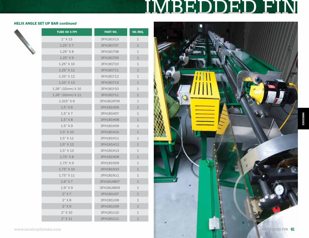
IMBEDDED FIN
www.mcelroyfintube.com
IMB
EDD
ED
IMBEDDED FIN 61
HELIX ANGLE SET UP BAR continued
TUBE OD X FPI PART NO. NO. REQ.
1” X 13 3FH181X13 1
1.25” X 7 3FH181T07 1
1.25” X 8 3FH181T08 1
1.25” X 9 3FH181T09 1
1.25” X 10 3FH181T10 1
1.25” X 11 3FH181T11 1
1.25” X 12 3FH181T12 1
1.25” X 13 3FH181T13 1
1.26” (32mm) X 10 3FH181Y10 1
1.26” (32mm) X 11 3FH181Y11 1
1.315” X 9 3FH181AF09 1
1.5” X 6 3FH181H06 1
1.5” X 7 3FH181H07 1
1.5” X 8 3FH181H08 1
1.5” X 9 3FH181H09 1
1.5” X 10 3FH181H10 1
1.5” X 11 3FH181H11 1
1.5” X 12 3FH181H12 1
1.5” X 13 3FH181H13 1
1.75” X 8 3FH181N08 1
1.75” X 9 3FH181N09 1
1.75” X 10 3FH181N10 1
1.75” X 11 3FH181N11 1
1.9” X 7 3FH181AB07 1
1.9” X 9 3FH181AB09 1
2” X 7 3FH181U07 1
2” X 8 3FH181U08 1
2” X 9 3FH181U09 1
2” X 10 3FH181U10 1
2” X 11 3FH181U11 1
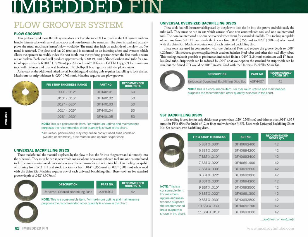
IMBEDDED FIN
www.mcelroyfintube.com
IMB
EDD
ED
62 IMBEDDED FIN
PLOW GROOVERThis preferred and more flexible system does not load the tube OD as much as the DT system and can
handle thinner tube walls as well as ferrous and non-ferrous tube materials. The plow is fixed and actually plows the metal much as a farmer’s plow would do. The metal rises high on each side of the plow tip. No metal is removed. The plow tool has 20 teeth and is mounted on an indexing arbor and overarm which allows the operator to readily index the next tooth into the working position when the first tooth is worn out or broken. Each tooth will produce approximately 3000’ (914m) of finned carbon steel tube for a to-tal of approximately 60,000’ (18,287m) per 20 tooth tool.* Reference GFTI-11 (pg 97) for minimum tube wall thickness and tube wall hardness. The Shell-pull Test is greater with the plow system.
As a result of the additional raised metal, backfilling and locking only requires flat rolling to lock the fin. Maximum fin strip thickness is .030” (.761mm). Machine requires one plow groover.
FIN STRIP THICKNESS RANGE PART NO. RECOMMENDED ORDER QTY.
.009” - .012” 3FH40101 50
.013” - .016” 3FH40102 50
.017” - .020” 3FH40103 50
.021” - .025” 3FH40104 50
.026” - .030” 3FH40105 50
DESCRIPTION PART NO. RECOMMENDED ORDER QTY.
Universal CBored Backfilling Disc A3FH404 42
DESCRIPTION PART NO. RECOMMENDED ORDER QTY.
Universal Oversized Backfilling Disc Set A3FH407 42
FPI X STRIP THICKNESS SET NO. RECOMMENDED ORDER QTY.
5 SST X .030” 3FH0692400 42
6 SST X .030” 3FH0694200 42
7 SST X .010” 3FH0693400 42
7 SST X .022” 3FH0691400 42
7 SST X .030” 3FH0692600 42
8 SST X .022” 3FH0692000 42
8 SST X .030” 3FH0694300 42
9 SST X .010” 3FH0693500 42
9 SST X .022” 3FH0691300 42
9 SST X .030” 3FH0692800 42
10 SST X .030” 3FH0692700 42
11 SST X .010” 3FH0693600 42
NOTE: This is a consumable item. For maximum uptime and maintenance purposes the recommended order quantity is shown in the chart.
NOTE: This is a consumable item. For maximum uptime and maintenance purposes the recommended order quantity is shown in the chart.
NOTE: This is a consumable item. For maximum uptime and maintenance purposes the recommended order quantity is shown in the chart.
NOTE: This is a consumable item. For maximum uptime and main-tenance purposes the recommended order quantity is shown in the chart.
*Actual tool performance may vary due to coolant used, tube condition (welded or seamless), tube material and operator experience.
UNIVERSAL BACKFILLING DISCSThese tools flat roll the material displaced by the plow to lock the fin into the groove and ultimately into
the tube wall. They must be run in sets which consist of one non-counterbored tool and one counterbored tool. The non-counterbored disc can be reversed when worn for extended tool life. This tooling is capable of running from 5-11 FPI and stock thicknesses from .014” (.355mm) to .020” (.508mm) when used with the Shim Kit. Machine requires one of each universal backfilling disc. These tools are for standard groove depth of .012” (.305mm)
UNIVERSAL OVERSIZED BACKFILLING DISCSThese tools flat roll the material displaced by the plow to lock the fin into the groove and ultimately the
tube wall. They must be run in sets which consist of one non-counterbored tool and one counterbored tool. The non-counterbored disc can be reversed when worn for extended tool life. This tooling is capable of running from 5-11 FPI and stock thicknesses from .014” (.355mm) to .020” (.508mm) when used with the Shim Kit. Machine requires one of each universal backfilling disc.
These tools are used in conjunction with the Universal Plow and reduce the groove depth to .008” (.203mm). This reduced groove application is used on Stainless Steel tubes and other thin wall alloy tubes. This tooling makes it possible to produce an imbedded fin in a .049” (1.24mm) minimum wall 1” Stain-less Steel tube. Strip width can be reduced by .004” or at your option the standard fin strip width can be run, but the finned OD would be .008” greater. Used with the Universal Backfiller Shim Kit.
SST BACKFILLING DISCSThis tooling is used for fin strip thicknesses greater than .020” (.508mm) and thinner than .014” (.355
mm) for FPI’s (Fins Per Inch) of 12 or finer and wider than 5 FPI. Used with Universal Backfilling Shim Kit. Set contains two backfilling discs.
...continued on next page
PLOW GROOVER SYSTEM
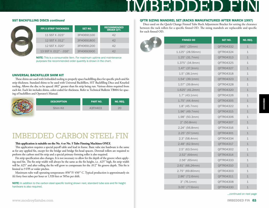
IMBEDDED FIN
IMBEDDED CARBON STEEL FINThis application is suitable on the No. 4 or No. 5 Tube Finning Machines ONLY. This application requires a special payoff table and lead in frame. Basic tube size hardware is the same
as for any applied fin, except for the bridge and bridge fin-head spacers. Dovetail rollers are required to preform the carbon steel fin strip and a special primary forming roller is also required.
Fin strip specification also changes. It is not necessary to allow for the depth of the groove when apply-ing steel fin. The fin strip width will always be the same as the fin height, i.e. .625” high, fin strip width will be .625” and after rolling the fin will grow to compensate for the .012” fin groove depth. This fin is limited to 9 FPI or wider pitches.
Maximum tube wall operating temperature: 850°F/ 450° C. Typical production is approximately six (6) forty foot tubes per hour or 1,920 feet or 585m per shift.
www.mcelroyfintube.com
IMB
EDD
ED
IMBEDDED FIN 63
FINNED OD SET NO. NO. REQ.
.985” (25mm) QFTR04332 1
1.125” (28.56mm) QFTR04324 1
1.25” (31.7mm) QFTR04313 1
1.375” (34.9mm) QFTR04325 1
1.47” (37.3mm) QFTR04327 1
1.5” (38.1mm) QFTR04318 1
1.54” (39.1mm) QFTR04323 1
1.57” (39.8mm) QFTR04328 1
1.625” (41.2mm) QFTR04320 1
1.7” (43.1mm) QFTR04326 1
1.75” (44.4mm) QFTR04305 1
1.8” (45.7mm) QFTR04322 1
1.96” (49.7mm) QFTR04315 1
1.98” (50.3mm) QFTR04306 1
2” (50.8mm) QFTR04307 1
2.24” (56.8mm) QFTR04316 1
2.25” (57.1mm) QFTR04301 1
2.3” (58.4mm) QFTR04334 1
2.48” (62.9mm) QFTR04317 1
2.5” (63.5mm) QFTR04302 1
2.52” (64mm) QFTR04314 1
2.56” (65mm) QFTR04333 1
2.61” (66.24mm) QFTR04310 1
2.75” (69.80mm) QFTR04303 1
2.86” (72.6mm) QFTR04311 1
3” (76.1mm) QFTR04308 1
3.05” (77.6mm) QFTR04330 1
www.mcelroyfintube.com
NOTE: This is a consumable item. For maximum uptime and maintenance purposes the recommended order quantity is shown in the chart.
SST BACKFILLING DISCS continued
FPI X STRIP THICKNESS SET NO. RECOMMENDED ORDER QTY.
11 SST X .023” 3FH0691100 42
12 SST X .012” 3FH0691800 42
12 SST X .020” 3FH0691200 42
13 SST X .012” - .016” 3FH0693900 42
DESCRIPTION PART NO. NO. REQ.
Shim Kit A3FH403 20
UNIVERSAL BACKFILLER SHIM KITThese shims are used with Imbedded tooling to properly space backfilling discs for specific pitch and fin
strip thickness. Standard shims to be used with Universal Backfillers, SST Backfilling Discs and Knurled tooling. Allows the disc to be spaced .002” greater than fin strip being run. Various shims required from each kit. Each kit includes shims, color-coded for thickness. Refer to Technical Bulletin TB004 for spac-ing of backfillers and Operator’s Manual.
NOTE: In addition to the carbon steel specific tooling shown next, standard tube size and fin height hardware is also required.
QFTR SIZING MANDREL SET (RACKS MANUFACTURED AFTER MARCH 1997)Discs used on the Quick Change Finned Tube Rack Adjustment Bracket for setting the clearance
between the rack rollers for a specific finned OD. The sizing mandrels are replaceable and specific for each finned OD.
...continued on next page
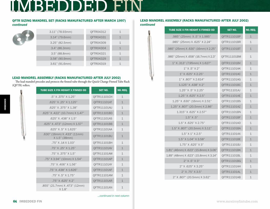
IMBEDDED FIN
www.mcelroyfintube.com
IMB
EDD
ED
64 IMBEDDED FIN
QFTR SIZING MANDREL SET (RACKS MANUFACTURED AFTER MARCH 1997)continued
3.11” (78.93mm) QFTR04312 1
3.14” (79.6mm) QFTR04331 1
3.25” (82.5mm) QFTR04309 1
3.4” (86.3mm) QFTR04304 1
3.5” (88.8mm) QFTR04321 1
3.58” (90.9mm) QFTR04329 1
3.61” (91.6mm) QFTR04319 1
LEAD MANDREL ASSEMBLY (RACKS MANUFACTURED AFTER JULY 2002)continued
LEAD MANDREL ASSEMBLY (RACKS MANUFACTURED AFTER JULY 2002)The lead mandrel precedes and protects the finned tube through the Quick Change Finned Tube Rack
(QFTR) rollers.
...continued in next column
TUBE SIZE X FIN HEIGHT X FINNED OD SET NO. NO. REQ.
.5” X .375” X 1.25” QFTR11101CH 1
.625” X .25” X 1.125” QFTR11101AT 1
.625” X .375” X 1.38” QFTR11101AU 1
.625” X .422” (10.7mm) X 1.47” QFTR11101BD 1
.625” X .438” X 1.5” QFTR11101AS 1
.625” X .473” (12mm) X 1.57” QFTR11101BB 1
.625” X .5” X 1.625” QFTR11101AA 1.630” (16mm) X .433” (11mm)
X 1.5” (38mm) QFTR11101BU 1
.75” X .14 X 1.03” QFTR11101BH 1
.75” X .25” X 1.25” QFTR11101AV 1
.75” X .375” X 1.5” QFTR11101AW 1
.75” X 3.94” (10mm) X 1.54” QFTR11101AP 1
.75” X .406” X 1.56” QFTR11101AY 1
.75” X .438” X 1.626” QFTR11101AF 1
.75” X .5” X 1.75” QFTR11101AM 1
.75” X .625” X 2” QFTR11101AR 1.855” (21.7mm) X .473” (12mm)
X 1.8” QFTR11101AN 1
TUBE SIZE X FIN HEIGHT X FINNED OD SET NO. NO. REQ.
.985” (25mm) X .5” X 1.985” QFTR11101BP 1
.985” (25mm) X .625” X 2.24” QFTR11101BR 1
.985” (25mm) X .630” (16mm) X 2.25” QFTR11101BT 1
.985” (25mm) X .658” (16.7mm) X 2.3” QFTR11101BM 1
1” X .313” (7.95mm) X 1.627” QFTR11101BV 1
1” X .5” X 2” QFTR11101AK 1
1” X .625” X 2.25” QFTR11101AC 1
1” X .807” X 2.614” QFTR11101AG 1
1.125” X .438” X 2” QFTR11101BC 1
1.25” X .5” X 2.25” QFTR11101AJ 1
1.25” X .625” X 2.5” QFTR11101AE 1
1.25” X .630” (16mm) X 2.51” QFTR11101BS 1
1.25” X .807” (20.5mm) X 2.86” QFTR11101AZ 1
1.315” X .625” X 2.57” QFTR11101BN 1
1.5” X .5” QFTR11101BF 1
1.5” X .625” X 2.75” QFTR11101AD 1
1.5” X .807” (20.5mm) X 3.11” QFTR11101BA 1
1.5” X 1” X 2.5” QFTR11101AX 1
1.5” X 1.04” X 3.58” QFTR11101BE 1
1.75” X .625” X 3” QFTR11101BJ 1
1.81” (46mm) X .623” (15.8mm) X 3.06” QFTR11101BK 1
1.89” (48mm) X .623” (15.8mm) X 3.14” QFTR11101BL 1
2” X .5” X 3” QFTR11101BG 1
2” X .625” X 3.25” QFTR11101AH 1
2” X .75” X 3.5” QFTR11101AL 1
2” X .807” (20.5mm) X 3.62” QFTR11101AB 1
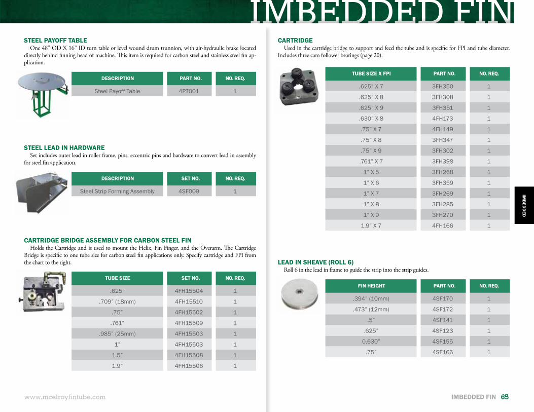
IMBEDDED FINSTEEL PAYOFF TABLE
One 48” OD X 16” ID turn table or level wound drum trunnion, with air-hydraulic brake located directly behind finning head of machine. This item is required for carbon steel and stainless steel fin ap-plication.
DESCRIPTION PART NO. NO. REQ.
Steel Payoff Table 4PT001 1
www.mcelroyfintube.com
IMB
EDD
ED
IMBEDDED FIN 65
DESCRIPTION SET NO. NO. REQ.
Steel Strip Forming Assembly 4SF009 1
TUBE SIZE SET NO. NO. REQ.
.625” 4FH15504 1
.709” (18mm) 4FH15510 1
.75” 4FH15502 1
.761” 4FH15509 1
.985” (25mm) 4FH15503 1
1” 4FH15503 1
1.5” 4FH15508 1
1.9” 4FH15506 1
TUBE SIZE X FPI PART NO. NO. REQ.
.625” X 7 3FH350 1
.625” X 8 3FH308 1
.625” X 9 3FH351 1
.630” X 8 4FH173 1
.75” X 7 4FH149 1
.75” X 8 3FH347 1
.75” X 9 3FH302 1
.761” X 7 3FH398 1
1” X 5 3FH268 1
1” X 6 3FH359 1
1” X 7 3FH269 1
1” X 8 3FH285 1
1” X 9 3FH270 1
1.9” X 7 4FH166 1
STEEL LEAD IN HARDWARESet includes outer lead in roller frame, pins, eccentric pins and hardware to convert lead in assembly
for steel fin application.
CARTRIDGE BRIDGE ASSEMBLY FOR CARBON STEEL FINHolds the Cartridge and is used to mount the Helix, Fin Finger, and the Overarm. The Cartridge
Bridge is specific to one tube size for carbon steel fin applications only. Specify cartridge and FPI from the chart to the right.
CARTRIDGEUsed in the cartridge bridge to support and feed the tube and is specific for FPI and tube diameter.
Includes three cam follower bearings (page 20).
FIN HEIGHT PART NO. NO. REQ.
.394” (10mm) 4SF170 1
.473” (12mm) 4SF172 1
.5” 4SF141 1
.625” 4SF123 1
0.630” 4SF155 1
.75” 4SF166 1
LEAD IN SHEAVE (ROLL 6)Roll 6 in the lead in frame to guide the strip into the strip guides.
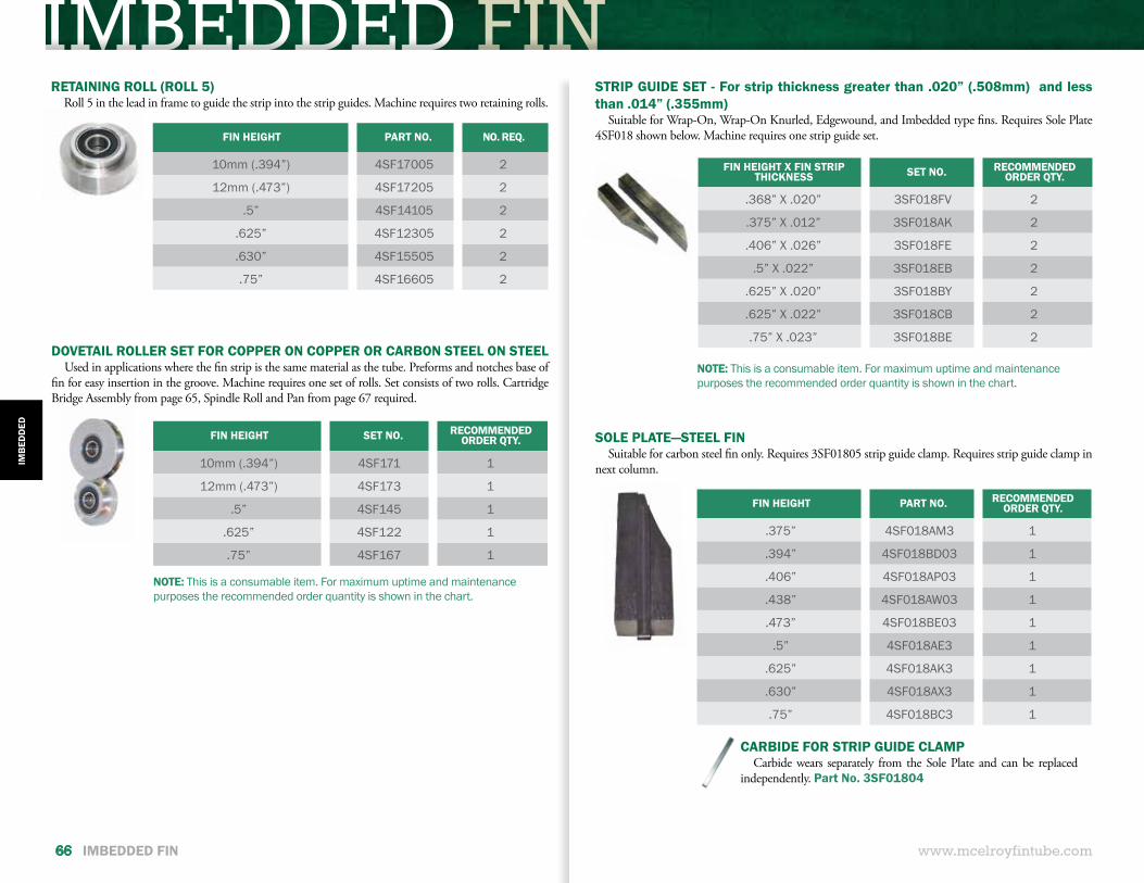
IMBEDDED FIN
www.mcelroyfintube.com66 IMBEDDED FIN
FIN HEIGHT X FIN STRIP THICKNESS SET NO. RECOMMENDED
ORDER QTY.
.368” X .020” 3SF018FV 2
.375” X .012” 3SF018AK 2
.406” X .026” 3SF018FE 2
.5” X .022” 3SF018EB 2
.625” X .020” 3SF018BY 2
.625” X .022” 3SF018CB 2
.75” X .023” 3SF018BE 2
FIN HEIGHT PART NO. RECOMMENDED ORDER QTY.
.375” 4SF018AM3 1
.394” 4SF018BD03 1
.406” 4SF018AP03 1
.438” 4SF018AW03 1
.473” 4SF018BE03 1
.5” 4SF018AE3 1
.625” 4SF018AK3 1
.630” 4SF018AX3 1
.75” 4SF018BC3 1
STRIP GUIDE SET - For strip thickness greater than .020” (.508mm) and less than .014” (.355mm)
Suitable for Wrap-On, Wrap-On Knurled, Edgewound, and Imbedded type fins. Requires Sole Plate 4SF018 shown below. Machine requires one strip guide set.
NOTE: This is a consumable item. For maximum uptime and maintenance purposes the recommended order quantity is shown in the chart.
CARBIDE FOR STRIP GUIDE CLAMPCarbide wears separately from the Sole Plate and can be replaced
independently. Part No. 3SF01804
SOLE PLATE—STEEL FINSuitable for carbon steel fin only. Requires 3SF01805 strip guide clamp. Requires strip guide clamp in
next column.
FIN HEIGHT PART NO. NO. REQ.
10mm (.394”) 4SF17005 2
12mm (.473”) 4SF17205 2
.5” 4SF14105 2
.625” 4SF12305 2
.630” 4SF15505 2
.75” 4SF16605 2
RETAINING ROLL (ROLL 5)Roll 5 in the lead in frame to guide the strip into the strip guides. Machine requires two retaining rolls.
NOTE: This is a consumable item. For maximum uptime and maintenance purposes the recommended order quantity is shown in the chart.
FIN HEIGHT SET NO. RECOMMENDED ORDER QTY.
10mm (.394”) 4SF171 1
12mm (.473”) 4SF173 1
.5” 4SF145 1
.625” 4SF122 1
.75” 4SF167 1
DOVETAIL ROLLER SET FOR COPPER ON COPPER OR CARBON STEEL ON STEELUsed in applications where the fin strip is the same material as the tube. Preforms and notches base of
fin for easy insertion in the groove. Machine requires one set of rolls. Set consists of two rolls. Cartridge Bridge Assembly from page 65, Spindle Roll and Pan from page 67 required.
IMB
EDD
ED
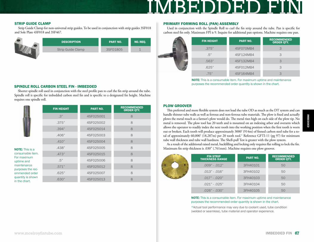
IMBEDDED FINDESCRIPTION PART NO. NO. REQ.
Strip Guide Clamp 3SFO1805 1
STRIP GUIDE CLAMPStrip Guide Clamp for non-universal strip guides. To be used in conjunction with strip guides 3SF018
and Sole Plate 4SF018 and 3SF467.
www.mcelroyfintube.com
IMB
EDD
ED
IMBEDDED FIN 67
FIN HEIGHT PART NO. RECOMMENDED ORDER QTY.
.3” 4SF025001 8
.375” 4SF025002 8
.394” 4SF025014 8
.406” 4SF025003 8
.410” 4SF025004 8
.438” 4SF025005 8
.473” 4SF025015 8
.5” 4SF025006 8
.571” 4SF025012 8
.625” 4SF025007 8
.630” 4SF025013 8
FIN HEIGHT PART NO. RECOMMENDED ORDER QTY.
.375” 4SF070MB4 3
.5” 4SF124MB4 3
.563” 4SF132MB4 3
.625” 4SF012MB4 3
.75” 4SF164MB4 3
NOTE: This is a consumable item. For maximum uptime and maintenance purposes the rec-ommended order quantity is shown in the chart.
NOTE: This is a consumable item. For maximum uptime and maintenance purposes the recommended order quantity is shown in the chart.
SPINDLE ROLL CARBON STEEL FIN - IMBEDDEDShorter spindle roll used in conjunction with the steel profile pan to curl the fin strip around the tube.
Spindle roll is specific for imbedded carbon steel fin and is specific to a designated fin height. Machine requires one spindle roll.
PRIMARY FORMING ROLL (PAN) ASSEMBLYUsed in conjunction with the Spindle Roll to curl the fin strip around the tube. Pan is specific for
carbon steel fin only. Maximum FPI is 9. Inquire for additional pan options. Machine requires one pan.
PLOW GROOVERThis preferred and more flexible system does not load the tube OD as much as the DT system and can
handle thinner tube walls as well as ferrous and non-ferrous tube materials. The plow is fixed and actually plows the metal much as a farmer’s plow would do. The metal rises high on each side of the plow tip. No metal is removed. The plow tool has 20 teeth and is mounted on an indexing arbor and overarm which allows the operator to readily index the next tooth into the working position when the first tooth is worn out or broken. Each tooth will produce approximately 3000’ (914m) of finned carbon steel tube for a to-tal of approximately 60,000’ (18,287m) per 20 tooth tool.* Reference GFTI-11 (pg 97) for minimum tube wall thickness and tube wall hardness. The Shell-pull Test is greater with the plow system.
As a result of the additional raised metal, backfilling and locking only requires flat rolling to lock the fin. Maximum fin strip thickness is .030” (.761mm). Machine requires one plow groover.
FIN STRIP THICKNESS RANGE PART NO. RECOMMENDED
ORDER QTY.
.009” - .012” 3FH40101 50
.013” - .016” 3FH40102 50
.017” - .020” 3FH40103 50
.021” - .025” 3FH40104 50
.026” - .030” 3FH40105 50
NOTE: This is a consumable item. For maximum uptime and maintenance purposes the recommended order quantity is shown in the chart.
*Actual tool performance may vary due to coolant used, tube condition (welded or seamless), tube material and operator experience.
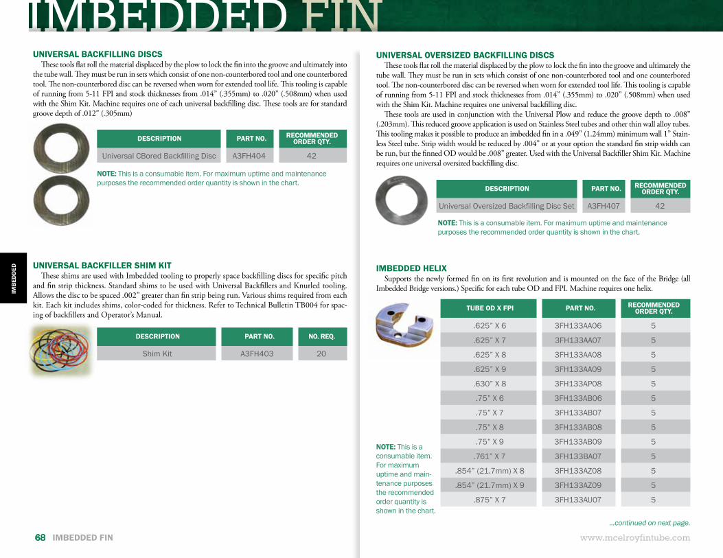
IMBEDDED FIN
www.mcelroyfintube.com
IMB
EDD
ED
68 IMBEDDED FIN
TUBE OD X FPI PART NO. RECOMMENDED ORDER QTY.
.625” X 6 3FH133AA06 5
.625” X 7 3FH133AA07 5
.625” X 8 3FH133AA08 5
.625” X 9 3FH133AA09 5
.630” X 8 3FH133AP08 5
.75” X 6 3FH133AB06 5
.75” X 7 3FH133AB07 5
.75” X 8 3FH133AB08 5
.75” X 9 3FH133AB09 5
.761” X 7 3FH133BA07 5
.854” (21.7mm) X 8 3FH133AZ08 5
.854” (21.7mm) X 9 3FH133AZ09 5
.875” X 7 3FH133AU07 5
IMBEDDED HELIXSupports the newly formed fin on its first revolution and is mounted on the face of the Bridge (all
Imbedded Bridge versions.) Specific for each tube OD and FPI. Machine requires one helix.
NOTE: This is a consumable item. For maximum uptime and main-tenance purposes the recommended order quantity is shown in the chart.
...continued on next page.
UNIVERSAL OVERSIZED BACKFILLING DISCSThese tools flat roll the material displaced by the plow to lock the fin into the groove and ultimately the
tube wall. They must be run in sets which consist of one non-counterbored tool and one counterbored tool. The non-counterbored disc can be reversed when worn for extended tool life. This tooling is capable of running from 5-11 FPI and stock thicknesses from .014” (.355mm) to .020” (.508mm) when used with the Shim Kit. Machine requires one universal backfilling disc.
These tools are used in conjunction with the Universal Plow and reduce the groove depth to .008” (.203mm). This reduced groove application is used on Stainless Steel tubes and other thin wall alloy tubes. This tooling makes it possible to produce an imbedded fin in a .049” (1.24mm) minimum wall 1” Stain-less Steel tube. Strip width would be reduced by .004” or at your option the standard fin strip width can be run, but the finned OD would be .008” greater. Used with the Universal Backfiller Shim Kit. Machine requires one universal oversized backfilling disc.
DESCRIPTION PART NO. RECOMMENDED ORDER QTY.
Universal Oversized Backfilling Disc Set A3FH407 42
NOTE: This is a consumable item. For maximum uptime and maintenance purposes the recommended order quantity is shown in the chart.
DESCRIPTION PART NO. NO. REQ.
Shim Kit A3FH403 20
UNIVERSAL BACKFILLER SHIM KITThese shims are used with Imbedded tooling to properly space backfilling discs for specific pitch
and fin strip thickness. Standard shims to be used with Universal Backfillers and Knurled tooling. Allows the disc to be spaced .002” greater than fin strip being run. Various shims required from each kit. Each kit includes shims, color-coded for thickness. Refer to Technical Bulletin TB004 for spac-ing of backfillers and Operator’s Manual.
UNIVERSAL BACKFILLING DISCSThese tools flat roll the material displaced by the plow to lock the fin into the groove and ultimately into
the tube wall. They must be run in sets which consist of one non-counterbored tool and one counterbored tool. The non-counterbored disc can be reversed when worn for extended tool life. This tooling is capable of running from 5-11 FPI and stock thicknesses from .014” (.355mm) to .020” (.508mm) when used with the Shim Kit. Machine requires one of each universal backfilling disc. These tools are for standard groove depth of .012” (.305mm)
DESCRIPTION PART NO. RECOMMENDED ORDER QTY.
Universal CBored Backfilling Disc A3FH404 42
NOTE: This is a consumable item. For maximum uptime and maintenance purposes the recommended order quantity is shown in the chart.
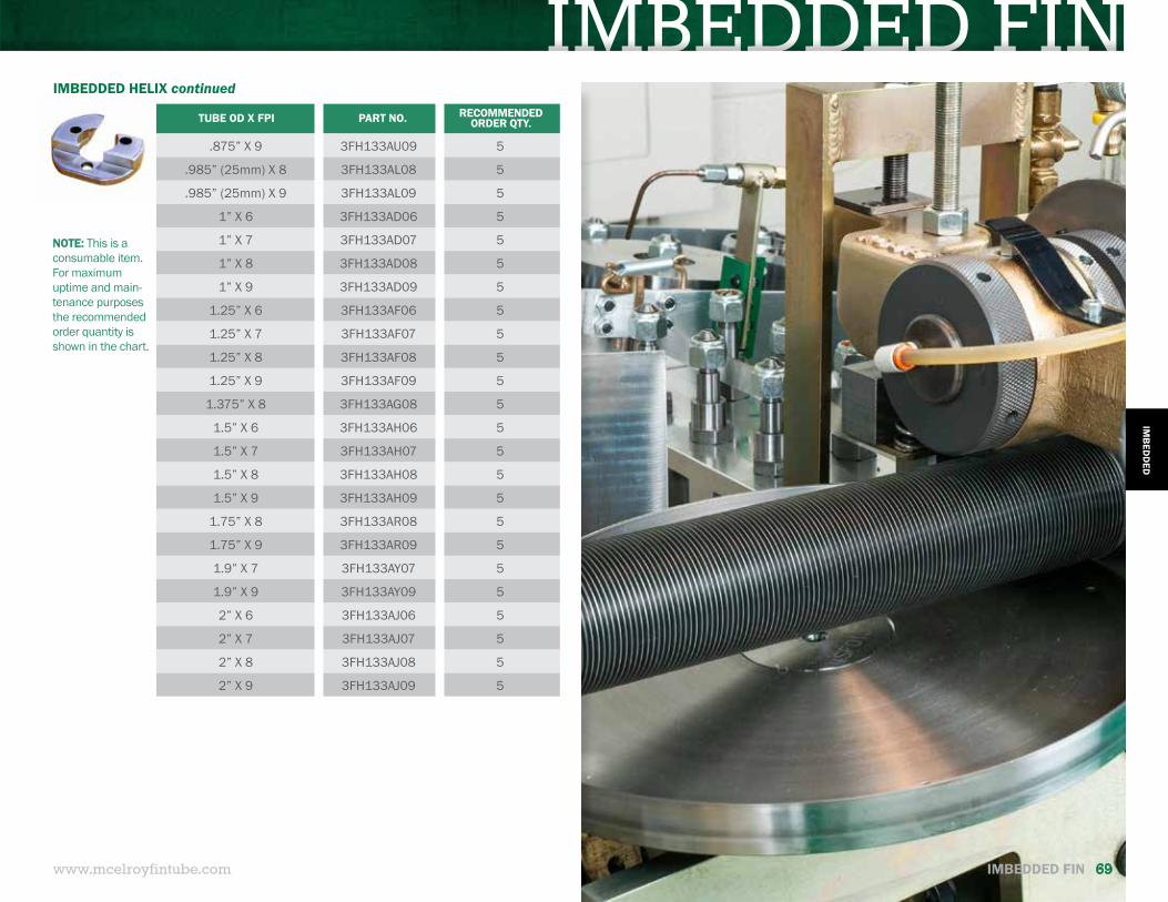
IMBEDDED FIN
www.mcelroyfintube.com
IMB
EDD
ED
IMBEDDED FIN 69
TUBE OD X FPI PART NO. RECOMMENDED ORDER QTY.
.875” X 9 3FH133AU09 5
.985” (25mm) X 8 3FH133AL08 5
.985” (25mm) X 9 3FH133AL09 5
1” X 6 3FH133AD06 5
1” X 7 3FH133AD07 5
1” X 8 3FH133AD08 5
1” X 9 3FH133AD09 5
1.25” X 6 3FH133AF06 5
1.25” X 7 3FH133AF07 5
1.25” X 8 3FH133AF08 5
1.25” X 9 3FH133AF09 5
1.375” X 8 3FH133AG08 5
1.5” X 6 3FH133AH06 5
1.5” X 7 3FH133AH07 5
1.5” X 8 3FH133AH08 5
1.5” X 9 3FH133AH09 5
1.75” X 8 3FH133AR08 5
1.75” X 9 3FH133AR09 5
1.9” X 7 3FH133AY07 5
1.9” X 9 3FH133AY09 5
2” X 6 3FH133AJ06 5
2” X 7 3FH133AJ07 5
2” X 8 3FH133AJ08 5
2” X 9 3FH133AJ09 5
IMBEDDED HELIX continued
NOTE: This is a consumable item. For maximum uptime and main-tenance purposes the recommended order quantity is shown in the chart.
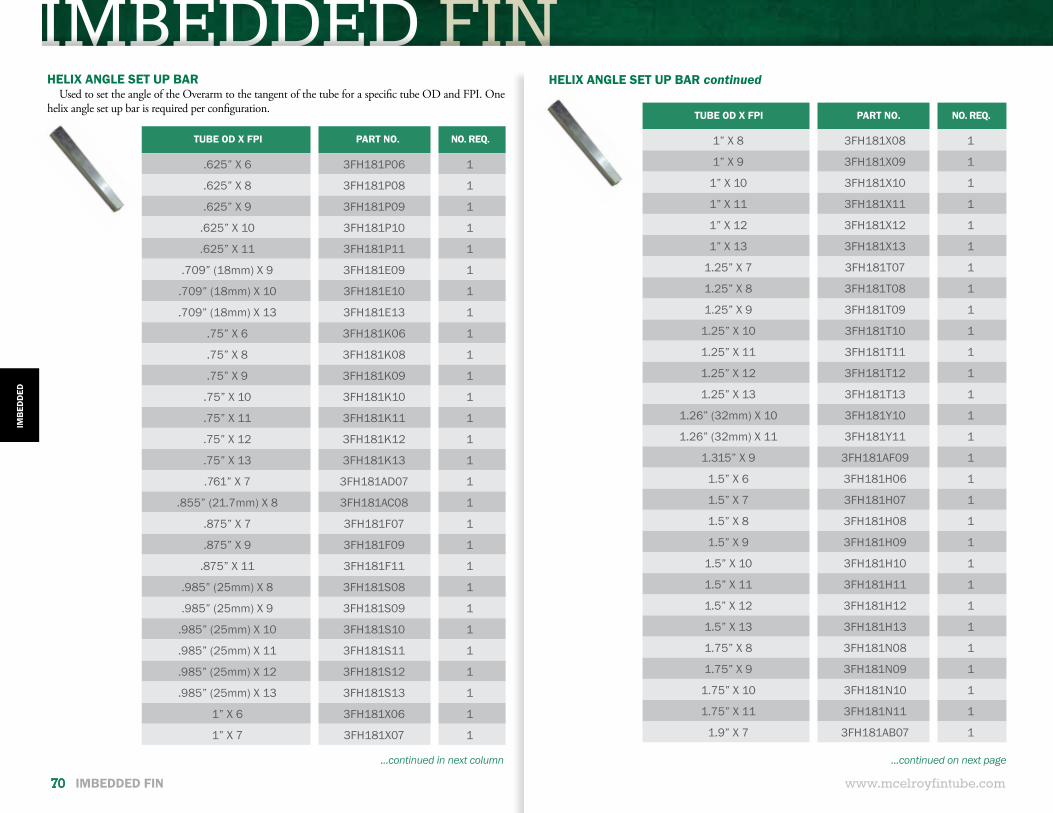
IMBEDDED FIN
www.mcelroyfintube.com
IMB
EDD
ED
70 IMBEDDED FIN
HELIX ANGLE SET UP BARUsed to set the angle of the Overarm to the tangent of the tube for a specific tube OD and FPI. One
helix angle set up bar is required per configuration.
TUBE OD X FPI PART NO. NO. REQ.
.625” X 6 3FH181P06 1
.625” X 8 3FH181P08 1
.625” X 9 3FH181P09 1
.625” X 10 3FH181P10 1
.625” X 11 3FH181P11 1
.709” (18mm) X 9 3FH181E09 1
.709” (18mm) X 10 3FH181E10 1
.709” (18mm) X 13 3FH181E13 1
.75” X 6 3FH181K06 1
.75” X 8 3FH181K08 1
.75” X 9 3FH181K09 1
.75” X 10 3FH181K10 1
.75” X 11 3FH181K11 1
.75” X 12 3FH181K12 1
.75” X 13 3FH181K13 1
.761” X 7 3FH181AD07 1
.855” (21.7mm) X 8 3FH181AC08 1
.875” X 7 3FH181F07 1
.875” X 9 3FH181F09 1
.875” X 11 3FH181F11 1
.985” (25mm) X 8 3FH181S08 1
.985” (25mm) X 9 3FH181S09 1
.985” (25mm) X 10 3FH181S10 1
.985” (25mm) X 11 3FH181S11 1
.985” (25mm) X 12 3FH181S12 1
.985” (25mm) X 13 3FH181S13 1
1” X 6 3FH181X06 1
1” X 7 3FH181X07 1
HELIX ANGLE SET UP BAR continued
...continued in next column ...continued on next page
TUBE OD X FPI PART NO. NO. REQ.
1” X 8 3FH181X08 1
1” X 9 3FH181X09 1
1” X 10 3FH181X10 1
1” X 11 3FH181X11 1
1” X 12 3FH181X12 1
1” X 13 3FH181X13 1
1.25” X 7 3FH181T07 1
1.25” X 8 3FH181T08 1
1.25” X 9 3FH181T09 1
1.25” X 10 3FH181T10 1
1.25” X 11 3FH181T11 1
1.25” X 12 3FH181T12 1
1.25” X 13 3FH181T13 1
1.26” (32mm) X 10 3FH181Y10 1
1.26” (32mm) X 11 3FH181Y11 1
1.315” X 9 3FH181AF09 1
1.5” X 6 3FH181H06 1
1.5” X 7 3FH181H07 1
1.5” X 8 3FH181H08 1
1.5” X 9 3FH181H09 1
1.5” X 10 3FH181H10 1
1.5” X 11 3FH181H11 1
1.5” X 12 3FH181H12 1
1.5” X 13 3FH181H13 1
1.75” X 8 3FH181N08 1
1.75” X 9 3FH181N09 1
1.75” X 10 3FH181N10 1
1.75” X 11 3FH181N11 1
1.9” X 7 3FH181AB07 1
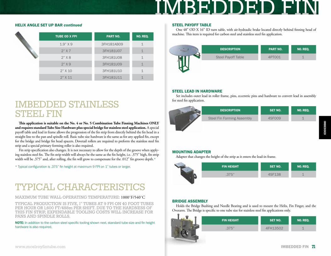
IMBEDDED FIN
www.mcelroyfintube.com
IMB
EDD
ED
IMBEDDED FIN 71
IMBEDDED STAINLESSSTEEL FIN
This application is suitable on the No. 4 or No. 5 Combination Tube Finning Machines ONLY and requires standard Tube Size Hardware plus special bridge for stainless steel application. A special payoff table and lead in frame allows the progression of the fin strip from directly behind the fin head in a straight line to the pan and spindle roll. Basic tube size hardware is the same as for any applied fin, except for the bridge and bridge fin head spacers. Dovetail rollers are required to preform the stainless steel fin strip and a special primary forming roller is also required.
Fin strip specification also changes. It is not necessary to allow for the depth of the groove when apply-ing stainless steel fin. The fin strip width will always be the same as the fin height, i.e. .375” high, fin strip width will be .375” and, after rolling, the fin will grow to compensate for the .012” fin groove depth.*
TYPICAL CHARACTERISTICSMAXIMUM TUBE WALL OPERATING TEMPERATURE: 1000˚F/540˚CTYPICAL PRODUCTION IS FIVE, 1” TUBES AT 9 FPI ON 40 FOOT TUBES PER HOUR OR 1,600 FT/488m PER SHIFT. DUE TO THE HARDNESS OF THIS FIN STRIP, EXPENDABLE TOOLING COSTS WILL INCREASE FOR PANS AND SPINDLE ROLLS.
STEEL PAYOFF TABLEOne 48” OD X 16” ID turn table, with air-hydraulic brake located directly behind finning head of
machine. This item is required for carbon steel and stainless steel fin application.
DESCRIPTION PART NO. NO. REQ.
Steel Payoff Table 4PT001 1
DESCRIPTION SET NO. NO. REQ.
Steel Fin Forming Assembly 4SF009 1
FIN HEIGHT SET NO. NO. REQ.
.375” 4SF138 1
FIN HEIGHT SET NO. NO. REQ.
.375” 4FH13502 1
STEEL LEAD IN HARDWARESet includes outer lead in roller frame, pins, eccentric pins and hardware to convert lead in assembly
for steel fin application.
MOUNTING ADAPTERAdapter that changes the height of the strip as it enters the lead-in frame.
BRIDGE ASSEMBLYHolds the Bridge Bushing and Needle Bearing and is used to mount the Helix, Fin Finger, and the
Overarm. The Bridge is specific to one tube size for stainless steel fin applications only.
NOTE: In addition to the carbon steel specific tooling shown next, standard tube size and fin height hardware is also required.
* Typical configuration is .375” fin height at maximum 9 FPI on 1” tubes or larger.
HELIX ANGLE SET UP BAR continued
TUBE OD X FPI PART NO. NO. REQ.
1.9” X 9 3FH181AB09 1
2” X 7 3FH181U07 1
2” X 8 3FH181U08 1
2” X 9 3FH181U09 1
2” X 10 3FH181U10 1
2” X 11 3FH181U11 1
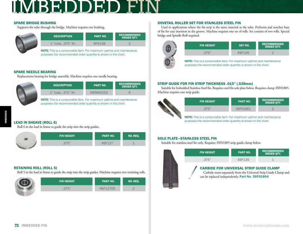
IMBEDDED FIN
www.mcelroyfintube.com
IMB
EDD
ED
72 IMBEDDED FIN
DESCRIPTION PART NO. RECOMMENDED ORDER QTY.
1” tube, .375” fin 4FH138 2
DESCRIPTION PART NO. RECOMMENDED ORDER QTY.
1” tube, .375” fin MDM00152 6
SPARE BRIDGE BUSHINGSupports the tube through the bridge. Machine requires one bushing.
SPARE NEEDLE BEARINGReplacement bearing for bridge assembly. Machine requires one needle bearing.
NOTE: This is a consumable item. For maximum uptime and maintenance purposes the recommended order quantity is shown in the chart.
NOTE: This is a consumable item. For maximum uptime and maintenance purposes the recommended order quantity is shown in the chart.
FIN HEIGHT PART NO. NO. REQ.
.375” 4SF12705 2
FIN HEIGHT PART NO. NO. REQ.
.375” 4SF127 1
LEAD IN SHEAVE (ROLL 6)Roll 6 in the lead in frame to guide the strip into the strip guides.
RETAINING ROLL (ROLL 5)Roll 5 in the lead in frame to guide the strip into the strip guides. Machine requires two retaining rolls.
NOTE: This is a consumable item. For maximum uptime and maintenance purposes the recommended order quantity is shown in the chart.
NOTE: This is a consumable item. For maximum uptime and maintenance purposes the recommended order quantity is shown in the chart.
FIN HEIGHT SET NO. RECOMMENDED ORDER QTY.
.375” 4SF126 2
FIN HEIGHT PART NO. RECOMMENDED ORDER QTY.
.375” 3SF018CL 2
DOVETAIL ROLLER SET FOR STAINLESS STEEL FIN Used in applications where the fin strip is the same material as the tube. Preforms and notches base
of fin for easy insertion in the groove. Machine requires one set of rolls. Set consists of two rolls. Special bridge and Spindle Roll required.
STRIP GUIDE FOR FIN STRIP THICKNESS .015” (.538mm) Suitable for Imbedded Stainless Steel fin. Requires steel fin sole plate below. Requires clamp 3SF01805.
Machine requires one strip guide.
FIN HEIGHT PART NO. RECOMMENDED ORDER QTY.
.375” 4SF135 1
CARBIDE FOR UNIVERSAL STRIP GUIDE CLAMPCarbide wears separately from the Universal Strip Guide Clamp and
can be replaced independently. Part No. 3SF01804
SOLE PLATE—STAINLESS STEEL FINSuitable for stainless steel fin only. Requires 3SF01805 strip guide clamp below.
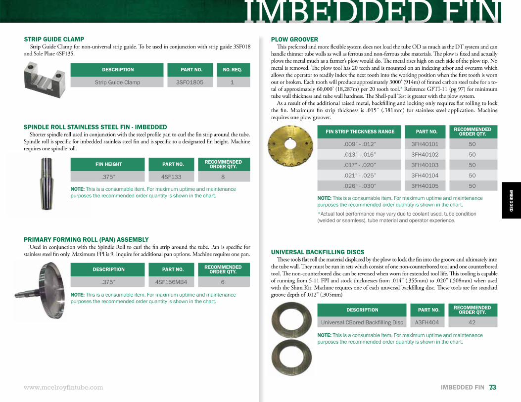
IMBEDDED FINDESCRIPTION PART NO. NO. REQ.
Strip Guide Clamp 3SFO1805 1
STRIP GUIDE CLAMPStrip Guide Clamp for non-universal strip guide. To be used in conjunction with strip guide 3SF018
and Sole Plate 4SF135.
www.mcelroyfintube.com
IMB
EDD
ED
IMBEDDED FIN 73
PRIMARY FORMING ROLL (PAN) ASSEMBLYUsed in conjunction with the Spindle Roll to curl the fin strip around the tube. Pan is specific for
stainless steel fin only. Maximum FPI is 9. Inquire for additional pan options. Machine requires one pan.
FIN HEIGHT PART NO. RECOMMENDED ORDER QTY.
.375” 4SF133 8
DESCRIPTION PART NO. RECOMMENDED ORDER QTY.
.375” 4SF156MB4 6
NOTE: This is a consumable item. For maximum uptime and maintenance purposes the recommended order quantity is shown in the chart.
SPINDLE ROLL STAINLESS STEEL FIN - IMBEDDEDShorter spindle roll used in conjunction with the steel profile pan to curl the fin strip around the tube.
Spindle roll is specific for imbedded stainless steel fin and is specific to a designated fin height. Machine requires one spindle roll.
PLOW GROOVERThis preferred and more flexible system does not load the tube OD as much as the DT system and can
handle thinner tube walls as well as ferrous and non-ferrous tube materials. The plow is fixed and actually plows the metal much as a farmer’s plow would do. The metal rises high on each side of the plow tip. No metal is removed. The plow tool has 20 teeth and is mounted on an indexing arbor and overarm which allows the operator to readily index the next tooth into the working position when the first tooth is worn out or broken. Each tooth will produce approximately 3000’ (914m) of finned carbon steel tube for a to-tal of approximately 60,000’ (18,287m) per 20 tooth tool.* Reference GFTI-11 (pg 97) for minimum tube wall thickness and tube wall hardness. The Shell-pull Test is greater with the plow system.
As a result of the additional raised metal, backfilling and locking only requires flat rolling to lock the fin. Maximum fin strip thickness is .015” (.381mm) for stainless steel application. Machine requires one plow groover.
FIN STRIP THICKNESS RANGE PART NO. RECOMMENDED ORDER QTY.
.009” - .012” 3FH40101 50
.013” - .016” 3FH40102 50
.017” - .020” 3FH40103 50
.021” - .025” 3FH40104 50
.026” - .030” 3FH40105 50
NOTE: This is a consumable item. For maximum uptime and maintenance purposes the recommended order quantity is shown in the chart.
*Actual tool performance may vary due to coolant used, tube condition (welded or seamless), tube material and operator experience.
NOTE: This is a consumable item. For maximum uptime and maintenance purposes the recommended order quantity is shown in the chart.
DESCRIPTION PART NO. RECOMMENDED ORDER QTY.
Universal CBored Backfilling Disc A3FH404 42
NOTE: This is a consumable item. For maximum uptime and maintenance purposes the recommended order quantity is shown in the chart.
UNIVERSAL BACKFILLING DISCSThese tools flat roll the material displaced by the plow to lock the fin into the groove and ultimately into
the tube wall. They must be run in sets which consist of one non-counterbored tool and one counterbored tool. The non-counterbored disc can be reversed when worn for extended tool life. This tooling is capable of running from 5-11 FPI and stock thicknesses from .014” (.355mm) to .020” (.508mm) when used with the Shim Kit. Machine requires one of each universal backfilling disc. These tools are for standard groove depth of .012” (.305mm)
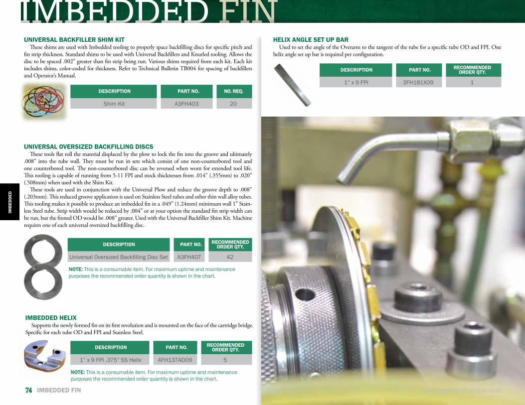
IMBEDDED FIN
www.mcelroyfintube.com
IMB
EDD
ED
74 IMBEDDED FIN
DESCRIPTION PART NO. NO. REQ.
Shim Kit A3FH403 20
DESCRIPTION PART NO. RECOMMENDED ORDER QTY.
1” x 9 FPI .375” SS Helix 4FH137AD09 5
DESCRIPTION PART NO. RECOMMENDED ORDER QTY.
1” x 9 FPI 3FH181X09 1
UNIVERSAL BACKFILLER SHIM KITThese shims are used with Imbedded tooling to properly space backfilling discs for specific pitch and
fin strip thickness. Standard shims to be used with Universal Backfillers and Knurled tooling. Allows the disc to be spaced .002” greater than fin strip being run. Various shims required from each kit. Each kit includes shims, color-coded for thickness. Refer to Technical Bulletin TB004 for spacing of backfillers and Operator’s Manual.
IMBEDDED HELIXSupports the newly formed fin on its first revolution and is mounted on the face of the cartridge bridge.
Specific for each tube OD and FPI and Stainless Steel.
HELIX ANGLE SET UP BARUsed to set the angle of the Overarm to the tangent of the tube for a specific tube OD and FPI. One
helix angle set up bar is required per configuration.
NOTE: This is a consumable item. For maximum uptime and maintenance purposes the recommended order quantity is shown in the chart.
UNIVERSAL OVERSIZED BACKFILLING DISCSThese tools flat roll the material displaced by the plow to lock the fin into the groove and ultimately
.008” into the tube wall. They must be run in sets which consist of one non-counterbored tool and one counterbored tool. The non-counterbored disc can be reversed when worn for extended tool life. This tooling is capable of running from 5-11 FPI and stock thicknesses from .014” (.355mm) to .020” (.508mm) when used with the Shim Kit.
These tools are used in conjunction with the Universal Plow and reduce the groove depth to .008” (.203mm). This reduced groove application is used on Stainless Steel tubes and other thin wall alloy tubes. This tooling makes it possible to produce an imbedded fin in a .049” (1.24mm) minimum wall 1” Stain-less Steel tube. Strip width would be reduced by .004” or at your option the standard fin strip width can be run, but the finned OD would be .008” greater. Used with the Universal Backfiller Shim Kit. Machine requires one of each universal oversized backfilling disc.
DESCRIPTION PART NO. RECOMMENDED ORDER QTY.
Universal Oversized Backfilling Disc Set A3FH407 42
NOTE: This is a consumable item. For maximum uptime and maintenance purposes the recommended order quantity is shown in the chart.

PERFORATED FIN
PERFORATED FINENHANCEMENT
www.mcelroyfintube.com
PERFO
RATED
PERFORATED FIN 75
This enhancement to the fin face creates slits much like the spokes of a wagon wheel or a small “tear drop.” The fin is preformed by a set of rollers and when it passes through the forming area of the spindle roll and primary forming roller the “tear drop” or spoke opens up. There is no loss of material.
The enhancement can be done in any type of Wrap-On (L-Fin), Overlapped Footed Fin (LL-Fin) or Imbed-ded (G-Fin) aluminum or copper fin. Some tooling is different for Wrap-On and for Imbedded perforated fins. Please refer to the appropriate section in this catalog.
The slit or “tear drop” increases heat transfer and can reduce the required amount of heat transfer surface. Each end user would need to determine the percentage of improvement offered by this enhancement over the plain fin. The industry has also accepted that this type of enhancement reduces the amount of air required and therefore decreases power costs.
PERFORATED FIN: Available for any Aluminum or Copper FinFINS PER INCH: 4– 12 FPITUBE MATERIAL: Ferrous, Non-Ferrous & Some AlloysFIN CONTACT:Primary Fin selection determines fin contactTYPE OF SERVICE: Primary Fin selection determines service levelMAXIMUM TUBE WALL OPERATING TEMPERATURE: Primary Fin selection determines the temperatureMAXIMUM TUBE RPM ON 1” TUBE: 3000
TYPICALCHARACTERISTICS
Note: If you have special requirements or need assistance, contact (918) 831-9236 or [email protected]
McELROY FINTUBE CALCULATOR CALCULATE FINNED OD, STRIP WIDTH,FIN TIP THICKNESS AND WEIGHT OF FIN MATERIALMOBILE AND WEB APPS SEE PAGE 36 FOR DETAILS
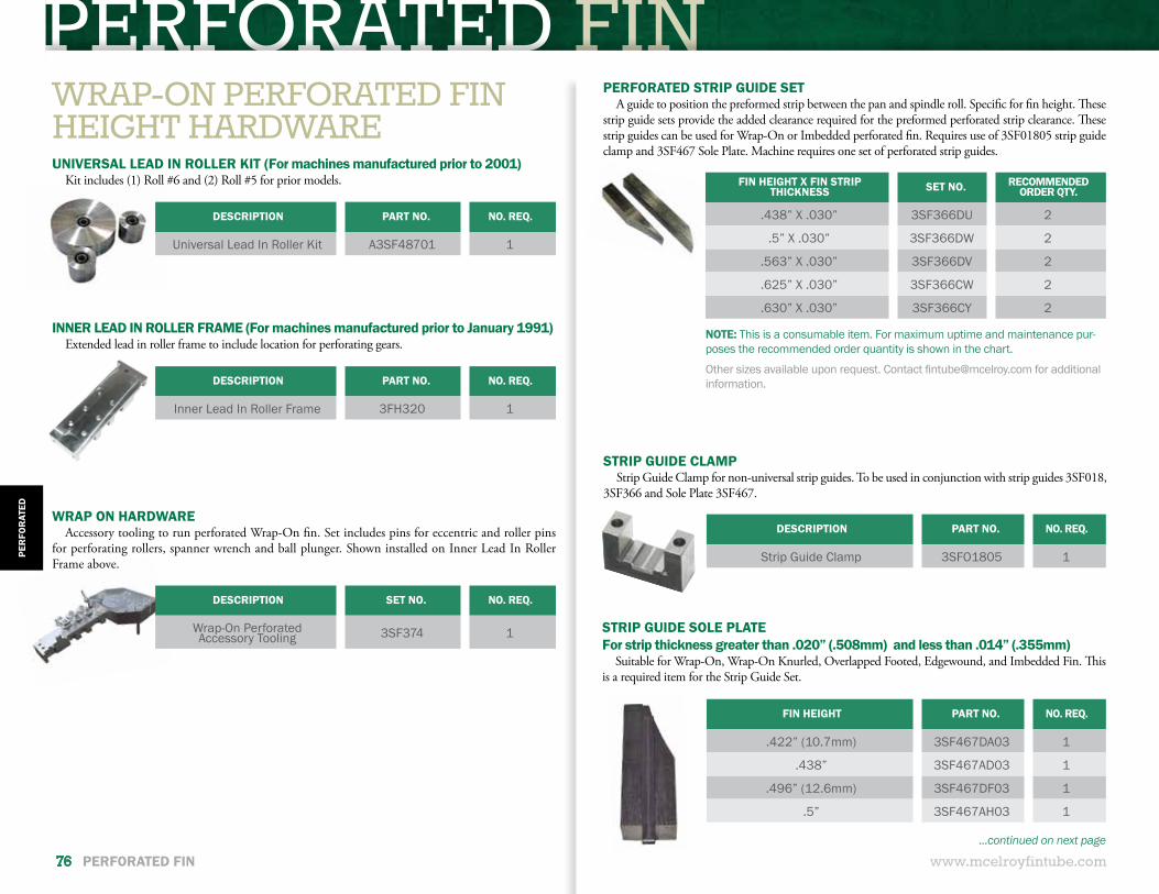
PERFORATED FIN
DESCRIPTION PART NO. NO. REQ.
Strip Guide Clamp 3SFO1805 1
STRIP GUIDE CLAMPStrip Guide Clamp for non-universal strip guides. To be used in conjunction with strip guides 3SF018,
3SF366 and Sole Plate 3SF467.
www.mcelroyfintube.com
PER
FOR
ATED
76 PERFORATED FIN
WRAP-ON PERFORATED FINHEIGHT HARDWAREUNIVERSAL LEAD IN ROLLER KIT (For machines manufactured prior to 2001)
Kit includes (1) Roll #6 and (2) Roll #5 for prior models.
INNER LEAD IN ROLLER FRAME (For machines manufactured prior to January 1991)Extended lead in roller frame to include location for perforating gears.
DESCRIPTION PART NO. NO. REQ.
Universal Lead In Roller Kit A3SF48701 1
DESCRIPTION PART NO. NO. REQ.
Inner Lead In Roller Frame 3FH320 1
DESCRIPTION SET NO. NO. REQ.
Wrap-On Perforated Accessory Tooling 3SF374 1
FIN HEIGHT X FIN STRIP THICKNESS SET NO. RECOMMENDED
ORDER QTY.
.438” X .030” 3SF366DU 2
.5” X .030” 3SF366DW 2
.563” X .030” 3SF366DV 2
.625” X .030” 3SF366CW 2
.630” X .030” 3SF366CY 2
WRAP ON HARDWAREAccessory tooling to run perforated Wrap-On fin. Set includes pins for eccentric and roller pins
for perforating rollers, spanner wrench and ball plunger. Shown installed on Inner Lead In Roller Frame above.
PERFORATED STRIP GUIDE SETA guide to position the preformed strip between the pan and spindle roll. Specific for fin height. These
strip guide sets provide the added clearance required for the preformed perforated strip clearance. These strip guides can be used for Wrap-On or Imbedded perforated fin. Requires use of 3SF01805 strip guide clamp and 3SF467 Sole Plate. Machine requires one set of perforated strip guides.
Other sizes available upon request. Contact [email protected] for additional information.
NOTE: This is a consumable item. For maximum uptime and maintenance pur-poses the recommended order quantity is shown in the chart.
FIN HEIGHT PART NO. NO. REQ.
.422” (10.7mm) 3SF467DA03 1
.438” 3SF467AD03 1
.496” (12.6mm) 3SF467DF03 1
.5” 3SF467AH03 1
STRIP GUIDE SOLE PLATEFor strip thickness greater than .020” (.508mm) and less than .014” (.355mm)
Suitable for Wrap-On, Wrap-On Knurled, Overlapped Footed, Edgewound, and Imbedded Fin. This is a required item for the Strip Guide Set.
...continued on next page
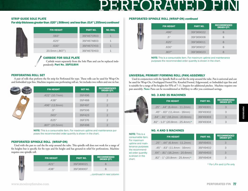
PERFORATED FIN
www.mcelroyfintube.com
PERFO
RATED
PERFORATED FIN 77
NOTE: This is a consumable item. For maximum uptime and maintenance pur-poses the recommended order quantity is shown in the chart.
NOTE: This is a consumable item. For maximum uptime and maintenance purposes the recommended order quantity is shown in the chart.
CARBIDE FOR SOLE PLATECarbide wears separately from the Sole Plate and can be replaced inde-
pendently. Part No. 3SF01804
STRIP GUIDE SOLE PLATEFor strip thickness greater than .020” (.508mm) and less than .014” (.355mm) continued
FIN HEIGHT PART NO. NO. REQ.
.563” 3SF467CR03 1
.625” 3SF467AB03 1
.630” 3SF467CY03 1
20.5mm (.807”) 3SF467EH03 1
FIN HEIGHT SET NO. RECOMMENDED ORDER QTY.
.422” (10.7mm) 3SF496 2
.438” 3SF488 2
.496” (12.6mm) 3SF497 2
.5” 3SF506 2
.563” 3SF423 2
.625” 3SF376 2
.807” (20.5mm) 3SF498 2
FIN HEIGHT PART NO. RECOMMENDED ORDER QTY.
.421” 3SF369021 8
.438” 3SF369007 8
PERFORATING ROLL SETA pair of rolls that preform the fin strip for Perforated fin type. These rolls can be used for Wrap-On
and Imbedded type fins. Machine requires one perforating roll set. Set includes two rollers and one tie bar.
PERFORATED SPINDLE ROLL (WRAP-ON)Used with the pan to curl the fin strip around the tube. This spindle roll does not work for a range of
fin heights but is specific for fin type and fin height and has ground-in relief for perforations. Machine requires one spindle roll.
PERFORATED SPINDLE ROLL (WRAP-ON) continued
FIN HEIGHT PART NO. RECOMMENDED ORDER QTY.
.496” 3SF369022 8
.5” 3SF369008 8
.625” 3SF369011 8
.630” 3SF369017 8
.807” 3SF369023 8
NOTE: This is a consumable item. For maximum uptime and main-tenance purposes the recommend-ed order quantity is shown in the chart.
FIN HEIGHT PART NO. RECOMMENDED ORDER QTY.
.25” - .44” (6.4mm - 11.2mm) 3SF49301 3
.45” - .63” (11.4mm - 16mm) 3SF49302 3
.64” - .81” (16.2mm - 20.6mm) 3SF49303 3
.82” - 1.0” (20.8mm - 25.4mm)* 3SF49304 3
FIN HEIGHT PART NO. RECOMMENDED ORDER QTY.
.25” - .44” (6.4mm - 11.2mm) 3SF49401 3
.45” - .63” (11.4mm - 16mm) 3SF49402 3
.64” - .81” (16.2mm - 20.6mm) 3SF49403 3
.82” - 1” (20.8mm - 25.4mm)* 3SF49404 3
UNIVERSAL PRIMARY FORMING ROLL (PAN) ASSEMBLYUsed in conjunction with the Spindle Roll to curl the fin strip around the tube. Pan is universal and can
be used for Wrap-On, Overlapped Footed Fin, Knurled Footed, Edgewound, or Imbedded type fins and is suitable for a range of fin heights for FPIs of 7-11. Inquire for additional pitches. Machine requires one pan assembly. Note: Pans can be reconditioned at McElroy to offer you continued savings.
NO. 3 AND 3S MACHINES
NO. 4 AND 5 MACHINES
* For L-Fin and LL-Fin only
...continued in next column
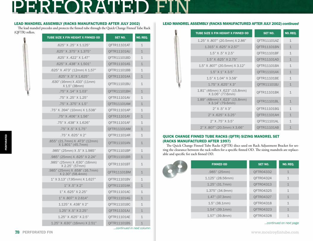
PERFORATED FIN
www.mcelroyfintube.com
PER
FOR
ATED
78 PERFORATED FIN
LEAD MANDREL ASSEMBLY (RACKS MANUFACTURED AFTER JULY 2002)The lead mandrel precedes and protects the finned tube through the Quick Change Finned Tube Rack
(QFTR) rollers.TUBE SIZE X FIN HEIGHT X FINNED OD SET NO. NO. REQ.
.625” X .25” X 1.125” QFTR11101AT 1
.625” X .375” X 1.375” QFTR11101AU 1
.625” X .422” X 1.47” QFTR11101BD 1
.625” X .438” X 1.501” QFTR11101AS 1
.625” X .473” (12mm) X 1.57” QFTR11101BB 1
.625” X .5” X 1.625” QFTR11101AA 1.630” (16mm) X .433” (11mm)
X 1.5” (38mm) QFTR11101BU 1
.75” X .14” X 1.03” QFTR11101BH 1
.75” X .25” X 1.25” QFTR11101AV 1
.75” X .375” X 1.5” QFTR11101AW 1
.75” X .394” (10mm) X 1.538” QFTR11101AP 1
.75” X .406” X 1.56” QFTR11101AY 1
.75” X .438” X 1.626” QFTR11101AF 1
.75” X .5” X 1.75” QFTR11101AM 1
.75” X .625” X 2” QFTR11101AR 1
.855” (21.7mm) X .473” (12mm) X 1.801” (45.7mm) QFTR11101AN 1
.985” (25mm) X .5” X 1.985” QFTR11101BP 1
.985” (25mm) X .625” X 2.24” QFTR11101BR 1.985” (25mm) X .630” (16mm)
X 2.25” (57mm) QFTR11101BT 1
.985” (25mm) X .658” (16.7mm) X 2.30” (58.4mm) QFTR11101BM 1
1” X 3.13” (7.95mm) X 1.627” QFTR11101BV 1
1” X .5” X 2” QFTR11101AK 1
1” X .625” X 2.25” QFTR11101AC 1
1” X .807” X 2.614” QFTR11101AG 1
1.125” X .438” X 2” QFTR11101BC 1
1.25” X .5” X 2.25” QFTR11101AJ 1
1.25” X .625” X 2.5” QFTR11101AE 1
1.25” X .630” (16mm) X 2.51” QFTR11101BS 1...continued in next column
TUBE SIZE X FIN HEIGHT X FINNED OD SET NO. NO. REQ.
1.25” X .807” (20.5mm) X 2.86” QFTR11101AZ 1
1.315” X .625” X 2.57” QFTR11101BN 1
1.5” X .5” X 2.5” QFTR11101BF 1
1.5” X .625” X 2.75” QFTR11101AD 1
1.5” X .807” (20.5mm) X 3.12” QFTR11101BA 1
1.5” X 1” X 3.5” QFTR11101AX 1
1.5” X 1.04” X 3.58” QFTR11101BE 1
1.75” X .625” X 3” QFTR11101BJ 1
1.81” (46mm) X .623” (15.8mm) X 3.06” (77.6mm) QFTR11101BK 1
1.89” (48mm) X .623” (15.8mm) X 3.14” (79.6mm) QFTR11101BL 1
2” X .5” X 3” QFTR11101BG 1
2” X .625” X 3.25” QFTR11101AH 1
2” X .75” X 3.5” QFTR11101AL 1
2” X .807” (20.5mm) X 3.66” QFTR11101AB 1
LEAD MANDREL ASSEMBLY (RACKS MANUFACTURED AFTER JULY 2002) continued
FINNED OD SET NO. NO. REQ.
.985” (25mm) QFTR04332 1
1.125” (28.56mm) QFTR04324 1
1.25” (31.7mm) QFTR04313 1
1.375” (34.9mm) QFTR04325 1
1.47” (37.3mm) QFTR04327 1
1.5” (38.1mm) QFTR04318 1
1.54” (39.1mm) QFTR04323 1
1.57” (39.8mm) QFTR04328 1
QUICK CHANGE FINNED TUBE RACKS (QFTR) SIZING MANDREL SET(RACKS MANUFACTURED AFTER 1997)
The Quick Change Finned Tube Racks (QFTR) discs used on Rack Adjustment Bracket for set-ting the clearance between the rack rollers for a specific finned OD. The sizing mandrels are replace-able and specific for each finned OD.
...continued on next page
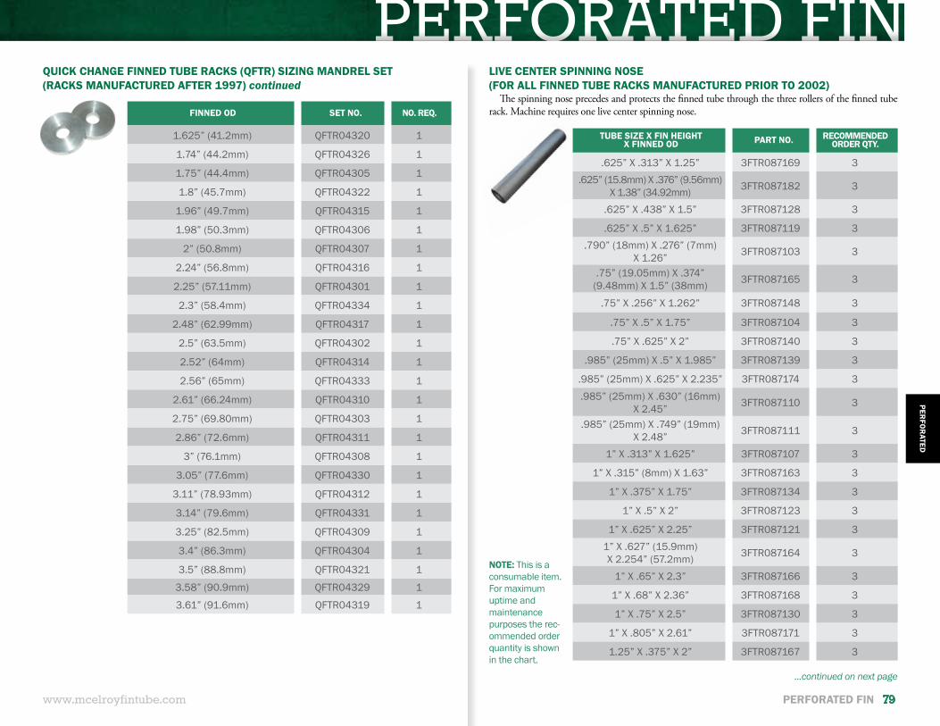
PERFORATED FIN
www.mcelroyfintube.com
PERFO
RATED
PERFORATED FIN 79
QUICK CHANGE FINNED TUBE RACKS (QFTR) SIZING MANDREL SET(RACKS MANUFACTURED AFTER 1997) continued
FINNED OD SET NO. NO. REQ.
1.625” (41.2mm) QFTR04320 1
1.74” (44.2mm) QFTR04326 1
1.75” (44.4mm) QFTR04305 1
1.8” (45.7mm) QFTR04322 1
1.96” (49.7mm) QFTR04315 1
1.98” (50.3mm) QFTR04306 1
2” (50.8mm) QFTR04307 1
2.24” (56.8mm) QFTR04316 1
2.25” (57.11mm) QFTR04301 1
2.3” (58.4mm) QFTR04334 1
2.48” (62.99mm) QFTR04317 1
2.5” (63.5mm) QFTR04302 1
2.52” (64mm) QFTR04314 1
2.56” (65mm) QFTR04333 1
2.61” (66.24mm) QFTR04310 1
2.75” (69.80mm) QFTR04303 1
2.86” (72.6mm) QFTR04311 1
3” (76.1mm) QFTR04308 1
3.05” (77.6mm) QFTR04330 1
3.11” (78.93mm) QFTR04312 1
3.14” (79.6mm) QFTR04331 1
3.25” (82.5mm) QFTR04309 1
3.4” (86.3mm) QFTR04304 1
3.5” (88.8mm) QFTR04321 1
3.58” (90.9mm) QFTR04329 1
3.61” (91.6mm) QFTR04319 1
TUBE SIZE X FIN HEIGHTX FINNED OD PART NO. RECOMMENDED
ORDER QTY.
.625” X .313” X 1.25” 3FTR087169 3.625” (15.8mm) X .376” (9.56mm)
X 1.38” (34.92mm) 3FTR087182 3
.625” X .438” X 1.5” 3FTR087128 3
.625” X .5” X 1.625” 3FTR087119 3.790” (18mm) X .276” (7mm)
X 1.26” 3FTR087103 3
.75” (19.05mm) X .374” (9.48mm) X 1.5” (38mm) 3FTR087165 3
.75” X .256” X 1.262” 3FTR087148 3
.75” X .5” X 1.75” 3FTR087104 3
.75” X .625” X 2” 3FTR087140 3
.985” (25mm) X .5” X 1.985” 3FTR087139 3
.985” (25mm) X .625” X 2.235” 3FTR087174 3
.985” (25mm) X .630” (16mm) X 2.45” 3FTR087110 3
.985” (25mm) X .749” (19mm) X 2.48” 3FTR087111 3
1” X .313” X 1.625” 3FTR087107 3
1” X .315” (8mm) X 1.63” 3FTR087163 3
1” X .375” X 1.75” 3FTR087134 3
1” X .5” X 2” 3FTR087123 3
1” X .625” X 2.25” 3FTR087121 31” X .627” (15.9mm) X 2.254” (57.2mm) 3FTR087164 3
1” X .65” X 2.3” 3FTR087166 3
1” X .68” X 2.36” 3FTR087168 3
1” X .75” X 2.5” 3FTR087130 3
1” X .805” X 2.61” 3FTR087171 3
1.25” X .375” X 2” 3FTR087167 3
LIVE CENTER SPINNING NOSE(FOR ALL FINNED TUBE RACKS MANUFACTURED PRIOR TO 2002)
The spinning nose precedes and protects the finned tube through the three rollers of the finned tube rack. Machine requires one live center spinning nose.
NOTE: This is a consumable item. For maximum uptime and maintenance purposes the rec-ommended order quantity is shown in the chart.
...continued on next page
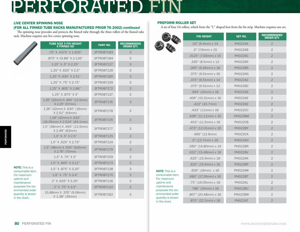
PERFORATED FIN
www.mcelroyfintube.com
PER
FOR
ATED
80 PERFORATED FIN
TUBE SIZE X FIN HEIGHTX FINNED OD PART NO. RECOMMENDED
ORDER QTY.
.75” X .4375” X 1.625” 3FTR087183 3
.875” X 15.88” X 2.126” 3FTR087184 3
1.25” X .5” X 2.25” 3FTR087127 3
1.25” X .625” X 2.5” 3FTR087126 3
1.25” X .630” X 2.51” 3FTR087180 3
1.25” X .75” X 2.75” 3FTR087109 3
1.25” X .805” X 2.86” 3FTR087172 3
1.25” X .875” X 3” 3FTR087137 31.26” (32mm) X .493” (12.5mm)
X 2.25” (57mm) 3FTR087176 3
1.26” (32mm) X .630” (16mm) X 2.52” (64mm) 3FTR087178 3
1.26” (32mm) X .632” (16.05mm) X 2.524” (64.1mm) 3FTR087135 3
1.5” (38mm) X .493” (12.5mm) X 2.49” (63mm) 3FTR087177 3
1.5” X .5” X 2.5” 3FTR087125 3
1.5” X .625” X 2.75” 3FTR087124 31.5” (38mm) X .630” (916mm)
X 2.76” (70mm) 3FTR087179 3
1.5” X .75” X 3” 3FTR087159 3
1.5” X .805” X 3.11” 3FTR087173 3
1.5” X .875” X 3.25” 3FTR087138 3
1.9” X .75” X 3.4” 3FTR087170 3
2” X .625” X 3.25” 3FTR087116 3
2” X .75” X 3.5” 3FTR087132 315.88mm X .376” (9.56mm)
X 1.38” (35mm) 3FTR087182 3
LIVE CENTER SPINNING NOSE(FOR ALL FINNED TUBE RACKS MANUFACTURED PRIOR TO 2002) continued
The spinning nose precedes and protects the finned tube through the three rollers of the finned tube rack. Machine requires one live center spinning nose.
NOTE: This is a consumable item. For maximum uptime and maintenance purposes the rec-ommended order quantity is shown in the chart.
PREFORM ROLLER SET A set of four (4) rollers, which form the “L” shaped foot from the fin strip. Machine requires one set.
NOTE: This is a consumable item. For maximum uptime and maintenance purposes the rec-ommended order quantity is shown in the chart.
FIN HEIGHT SET NO. RECOMMENDED ORDER QTY.
.25” (6.4mm) x 14 PH022AA 2
.3” (7.6mm) x 15 PH022AB 2
.3125” (7.93mm) x 15 PH022AC 2
.335” (8.5mm) x 12 PH022BX 2
.365” (9.26mm) x 16 PH022BS 2
.375” (9.51mm) x 16 PH022AN 2
.375” (9.51mm) x 14 PH022AZ 2
.375” (9.51mm) x 12 PH022BC 2
.394” (10mm) x 16 PH022AS 2
.406” (10.31mm) x 16 PH022AE 2
.422” (10.7mm) PH022BZ 2
.433” (11mm) x 16 PHO22CC 2
.438” (11.11mm) x 16 PH022BM 2
.453” (11.5mm) x 16 PH022CB 2
.473” (12.01mm) x 16 PH022BY 2
.469” (12.6mm) PH022CA 2
.5” (12.7mm) x 16 PH022AH 2
.583” (14.80mm) x 14 PH022BR 2
.610” (15.48mm) x 16 PH022BV 2
.625” (15.9mm) x 18 PH022AK 2
.625” (15.9mm) x 16 PH022BP 2
.630” (16mm) x 16 PH022AW 2
.680” (17.26mm) x 16 PH022BT 2
.75” (19.05mm) x 18 PH022AL 2
.788” (20mm) x 16 PH022BU 2
.807” (20.48mm) x 16 PH022BW 2
.875” (22.2mm) x 18 PH022AT 2
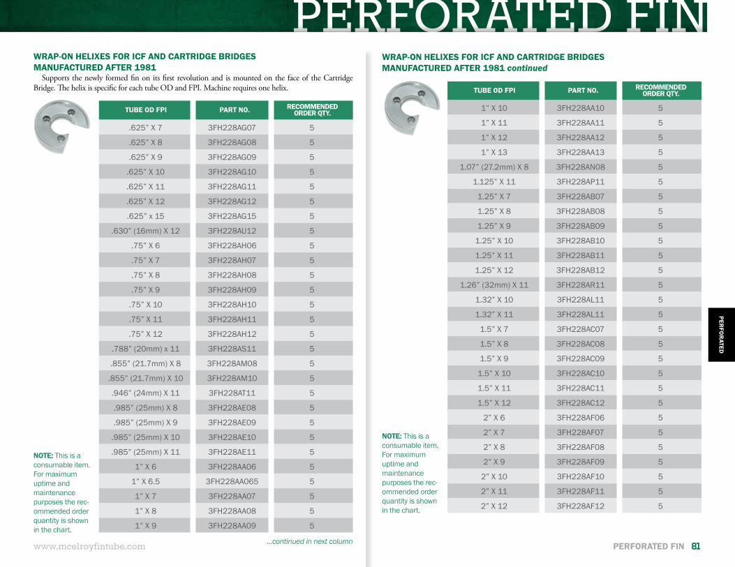
PERFORATED FIN
www.mcelroyfintube.com
PERFO
RATED
PERFORATED FIN 81
TUBE OD FPI PART NO. RECOMMENDED ORDER QTY.
.625” X 7 3FH228AG07 5
.625” X 8 3FH228AG08 5
.625” X 9 3FH228AG09 5
.625” X 10 3FH228AG10 5
.625” X 11 3FH228AG11 5
.625” X 12 3FH228AG12 5
.625” x 15 3FH228AG15 5
.630” (16mm) X 12 3FH228AU12 5
.75” X 6 3FH228AH06 5
.75” X 7 3FH228AH07 5
.75” X 8 3FH228AH08 5
.75” X 9 3FH228AH09 5
.75” X 10 3FH228AH10 5
.75” X 11 3FH228AH11 5
.75” X 12 3FH228AH12 5
.788” (20mm) x 11 3FH228AS11 5
.855” (21.7mm) X 8 3FH228AM08 5
.855” (21.7mm) X 10 3FH228AM10 5
.946” (24mm) X 11 3FH228AT11 5
.985” (25mm) X 8 3FH228AE08 5
.985” (25mm) X 9 3FH228AE09 5
.985” (25mm) X 10 3FH228AE10 5
.985” (25mm) X 11 3FH228AE11 5
1” X 6 3FH228AA06 5
1” X 6.5 3FH228AA065 5
1” X 7 3FH228AA07 5
1” X 8 3FH228AA08 5
1” X 9 3FH228AA09 5
WRAP-ON HELIXES FOR ICF AND CARTRIDGE BRIDGESMANUFACTURED AFTER 1981
Supports the newly formed fin on its first revolution and is mounted on the face of the Cartridge Bridge. The helix is specific for each tube OD and FPI. Machine requires one helix.
WRAP-ON HELIXES FOR ICF AND CARTRIDGE BRIDGESMANUFACTURED AFTER 1981 continued
...continued in next column
TUBE OD FPI PART NO. RECOMMENDED ORDER QTY.
1” X 10 3FH228AA10 5
1” X 11 3FH228AA11 5
1” X 12 3FH228AA12 5
1” X 13 3FH228AA13 5
1.07” (27.2mm) X 8 3FH228AN08 5
1.125” X 11 3FH228AP11 5
1.25” X 7 3FH228AB07 5
1.25” X 8 3FH228AB08 5
1.25” X 9 3FH228AB09 5
1.25” X 10 3FH228AB10 5
1.25” X 11 3FH228AB11 5
1.25” X 12 3FH228AB12 5
1.26” (32mm) X 11 3FH228AR11 5
1.32” X 10 3FH228AL11 5
1.32” X 11 3FH228AL11 5
1.5” X 7 3FH228AC07 5
1.5” X 8 3FH228AC08 5
1.5” X 9 3FH228AC09 5
1.5” X 10 3FH228AC10 5
1.5” X 11 3FH228AC11 5
1.5” X 12 3FH228AC12 5
2” X 6 3FH228AF06 5
2” X 7 3FH228AF07 5
2” X 8 3FH228AF08 5
2” X 9 3FH228AF09 5
2” X 10 3FH228AF10 5
2” X 11 3FH228AF11 5
2” X 12 3FH228AF12 5
NOTE: This is a consumable item. For maximum uptime and maintenance purposes the rec-ommended order quantity is shown in the chart.
NOTE: This is a consumable item. For maximum uptime and maintenance purposes the rec-ommended order quantity is shown in the chart.
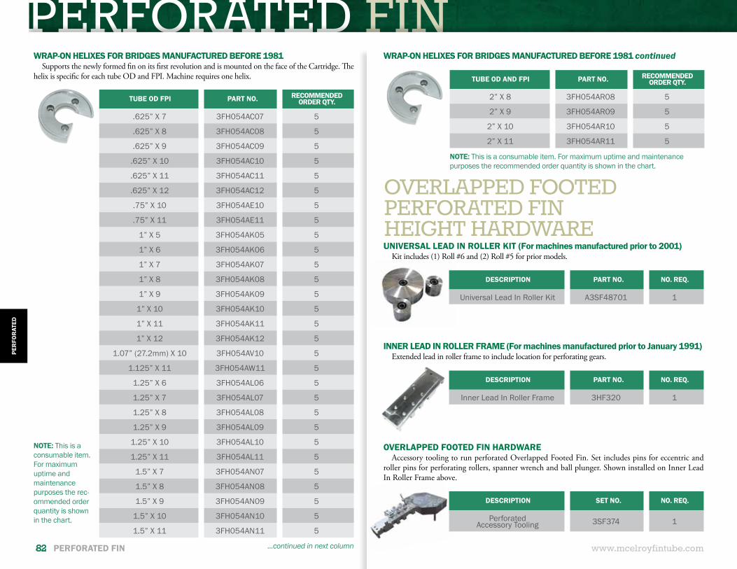
PERFORATED FIN
www.mcelroyfintube.com
PER
FOR
ATED
82 PERFORATED FIN
OVERLAPPED FOOTED PERFORATED FINHEIGHT HARDWARE
...continued in next column
WRAP-ON HELIXES FOR BRIDGES MANUFACTURED BEFORE 1981Supports the newly formed fin on its first revolution and is mounted on the face of the Cartridge. The
helix is specific for each tube OD and FPI. Machine requires one helix.
TUBE OD FPI PART NO. RECOMMENDED ORDER QTY.
.625” X 7 3FH054AC07 5
.625” X 8 3FH054AC08 5
.625” X 9 3FH054AC09 5
.625” X 10 3FH054AC10 5
.625” X 11 3FH054AC11 5
.625” X 12 3FH054AC12 5
.75” X 10 3FH054AE10 5
.75” X 11 3FH054AE11 5
1” X 5 3FH054AK05 5
1” X 6 3FH054AK06 5
1” X 7 3FH054AK07 5
1” X 8 3FH054AK08 5
1” X 9 3FH054AK09 5
1” X 10 3FH054AK10 5
1” X 11 3FH054AK11 5
1” X 12 3FH054AK12 5
1.07” (27.2mm) X 10 3FH054AV10 5
1.125” X 11 3FH054AW11 5
1.25” X 6 3FH054AL06 5
1.25” X 7 3FH054AL07 5
1.25” X 8 3FH054AL08 5
1.25” X 9 3FH054AL09 5
1.25” X 10 3FH054AL10 5
1.25” X 11 3FH054AL11 5
1.5” X 7 3FH054AN07 5
1.5” X 8 3FH054AN08 5
1.5” X 9 3FH054AN09 5
1.5” X 10 3FH054AN10 5
1.5” X 11 3FH054AN11 5
NOTE: This is a consumable item. For maximum uptime and maintenance purposes the rec-ommended order quantity is shown in the chart.
WRAP-ON HELIXES FOR BRIDGES MANUFACTURED BEFORE 1981 continued
TUBE OD AND FPI PART NO. RECOMMENDED ORDER QTY.
2” X 8 3FH054AR08 5
2” X 9 3FH054AR09 5
2” X 10 3FH054AR10 5
2” X 11 3FH054AR11 5
NOTE: This is a consumable item. For maximum uptime and maintenance purposes the recommended order quantity is shown in the chart.
UNIVERSAL LEAD IN ROLLER KIT (For machines manufactured prior to 2001)Kit includes (1) Roll #6 and (2) Roll #5 for prior models.
INNER LEAD IN ROLLER FRAME (For machines manufactured prior to January 1991)Extended lead in roller frame to include location for perforating gears.
DESCRIPTION PART NO. NO. REQ.
Universal Lead In Roller Kit A3SF48701 1
DESCRIPTION PART NO. NO. REQ.
Inner Lead In Roller Frame 3HF320 1
DESCRIPTION SET NO. NO. REQ.
Perforated Accessory Tooling 3SF374 1
OVERLAPPED FOOTED FIN HARDWAREAccessory tooling to run perforated Overlapped Footed Fin. Set includes pins for eccentric and
roller pins for perforating rollers, spanner wrench and ball plunger. Shown installed on Inner Lead In Roller Frame above.
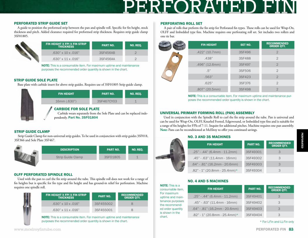
PERFORATED FIN
DESCRIPTION PART NO. NO. REQ.
Strip Guide Clamp 3SFO1805 1
STRIP GUIDE CLAMPStrip Guide Clamp for non-universal strip guides. To be used in conjunction with strip guides 3SF018,
3SF366 and Sole Plate 3SF467.
www.mcelroyfintube.com
PERFO
RATED
PERFORATED FIN 83
STRIP GUIDE SOLE PLATEBase plate with carbide insert for above strip guides. Requires use of 3SF01805 Strip guide clamp.
FIN HEIGHT PART NO. NO. REQ.
16mm (.630”) 3SF467CY03 1
FIN HEIGHT X FPI X FIN STRIP THICKNESS PART NO. RECOMMENDED
ORDER QTY.
.630” x 10 x .016” 3SF455002 8
.630” x 11 x .016” 3SF455001 8
FIN HEIGHT X FPI X FIN STRIP THICKNESS PART NO. NO. REQ.
.630” x 10 x .016” 3SF456AB 2
.630” x 11 x .016” 3SF456AA 2
PERFORATED STRIP GUIDE SETA guide to position the preformed strip between the pan and spindle roll. Specific for fin height, stock
thickness and pitch. Added clearance required for preformed strip thickness. Requires strip guide clamp 3SF01805.
OLFF PERFORATED SPINDLE ROLLUsed with the pan to curl the fin strip around the tube. This spindle roll does not work for a range of
fin heights but is specific for fin type and fin height and has ground-in relief for perforation. Machine requires one spindle roll.
NOTE: This is a consumable item. For maximum uptime and maintenance purposes the recommended order quantity is shown in the chart.
NOTE: This is a consumable item. For maximum uptime and main-tenance purposes the recommend-ed order quantity is shown in the chart.
FIN HEIGHT PART NO. RECOMMENDED ORDER QTY.
.25” - .44” (6.4mm - 11.2mm) 3SF49301 3
.45” - .63” (11.4mm - 16mm) 3SF49302 3
.64” - .81” (16.2mm - 20.6mm) 3SF49303 3
.82” - 1” (20.8mm - 25.4mm)* 3SF49304 3
FIN HEIGHT PART NO. RECOMMENDED ORDER QTY.
.25” - .44” (6.4mm - 11.2mm) 3SF49401 3
.45” - .63” (11.4mm - 16mm) 3SF49402 3
.64” - .81” (16.2mm - 20.6mm) 3SF49403 3
.82” - 1” (20.8mm - 25.4mm)* 3SF49404 3
NO. 3 AND 3S MACHINES
NO. 4 AND 5 MACHINES
* For L-Fin and LL-Fin only
UNIVERSAL PRIMARY FORMING ROLL (PAN) ASSEMBLYUsed in conjunction with the Spindle Roll to curl the fin strip around the tube. Pan is universal and
can be used for Wrap-On, OLFF, Knurled Footed, Edgewound, or Imbedded type fins and is suitable for a range of fin heights for FPIs of 7-11. Inquire for additional pitches. Machine requires one pan assembly. Note: Pans can be reconditioned at McElroy to offer you continued savings.
NOTE: This is a consumable item. For maximum uptime and maintenance pur-poses the recommended order quantity is shown in the chart.
FIN HEIGHT SET NO. RECOMMENDED ORDER QTY.
.422” (10.7mm) 3SF496 2
.438” 3SF488 2
.496” (12.6mm) 3SF497 2
.5” 3SF506 2
.563” 3SF423 2
.625” 3SF376 2
.807” (20.5mm) 3SF498 2
PERFORATING ROLL SETA pair of rolls that preform the fin strip for Perforated fin types. These rolls can be used for Wrap-On,
OLFF and Imbedded type fins. Machine requires one perforating roll set. Set includes two rollers and one tie bar.
NOTE: This is a consumable item. For maximum uptime and maintenance purposes the recommended order quantity is shown in the chart.
CARBIDE FOR SOLE PLATECarbide wears separately from the Sole Plate and can be replaced inde-
pendently. Part No. 3SF01804
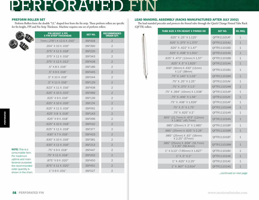
PERFORATED FIN
...continued on next page
www.mcelroyfintube.com
PER
FOR
ATED
84 PERFORATED FIN
LEAD MANDREL ASSEMBLY (RACKS MANUFACTURED AFTER JULY 2002)The lead mandrel precedes and protects the finned tube through the Quick Change Finned Tube Rack
(QFTR) rollers.TUBE SIZE X FIN HEIGHT X FINNED OD SET NO. NO. REQ.
.625” X .25” X 1.125” QFTR11101AT 1
.625” X .375” X 1.375” QFTR11101AU 1
.625” X .422” X 1.47” QFTR11101BD 1
.625” X .438” X 1.501” QFTR11101AS 1
.625” X .473” (12mm) X 1.57” QFTR11101BB 1
.625” X .5” X 1.625” QFTR11101AA 1.630” (16mm) X .433” (11mm)
X 1.5” (38mm) QFTR11101BU 1
.75” X .140” X 1.03” QFTR11101BH 1
.75” X .25” X 1.25” QFTR11101AV 1
.75” X .375” X 1.5” QFTR11101AW 1
.75” X .394” (10mm) X 1.538” QFTR11101AP 1
.75” X .406” X 1.56” QFTR11101AY 1
.75” X .438” X 1.626” QFTR11101AF 1
.75” X .5” X 1.75” QFTR11101AM 1
.75” X .625” X 2” QFTR11101AR 1
.855” (21.7mm) X .473” (12mm) X 1.801” (45.7mm) QFTR11101AN 1
.985” (25mm) X .5” X 1.985” QFTR11101BP 1
.985” (25mm) X .625” X 2.24” QFTR11101BR 1
.985” (25mm) X .63” (16mm) X 2.25” (57mm) QFTR11101BT 1
.985” (25mm) X .658” (16.7mm) X 2.30” (58.4mm) QFTR11101BM 1
1” X 3.13” (7.95mm) X 1.627” QFTR11101BV 1
1” X .5” X 2” QFTR11101AK 1
1” X .625” X 2.25” QFTR11101AC 1
1” X .807” X 2.614” QFTR11101AG 1
PREFORM ROLLER SETPreform Rollers form the double “LL” shaped foot from the fin strip. These preform rollers are specific
for fin height, FPI and Fin Strip Thickness. Machine requires one set of preform rollers.
FIN HEIGHT X FPI X FIN STRIP THICKNESS SET NO. RECOMMENDED
ORDER QTY.
7mm (.276”) X 12.5 X .010” 3SF418 2
.354” X 10 X .016” 3SF390 2
.375” X 11 X .018” 3SF220 2
.375” X 11 X .016” 3SF343 2
.375” X 12 X .012” 3SF428 2
.5” X 8 X .016” 3SF186 2
.5” X 9 X .016” 3SF445 2
.5” X 10 X .016” 3SF044 2
.5” X 11 X .016” 3SF129 2
.623” X 11 X .016” 3SF408 2
.625” X 10 X .015” 3SF466 2
.625” X 9 X .016” 3SF139 2
.625” X 10 X .016” 3SF174 2
.625” X 11 X .016” 3SF091 2
.625” X 8 X .018” 3SF143 2
.625” X 9 X .018” 3SF096 2
.625” X 10 X .018” 3SF010 2
.625” X 11 X .018” 3SF377 2
.630” X 7 X .016” 3SF433 2
.630” X 10 X .016” 3SF381 2
.630” X 11 X .016” 3SF213 2
.75” X 9 X .018” 3SF447 2
.75” X 11 X .018” 3SF202 2
.875” X 9 X .020” 3SF450 2
.875” X 11 X .020” 3SF451 2
1” X 9 X .031” 3SF027 2
NOTE: This is a consumable item. For maximum uptime and main-tenance purposes the recommended order quantity is shown in the chart.
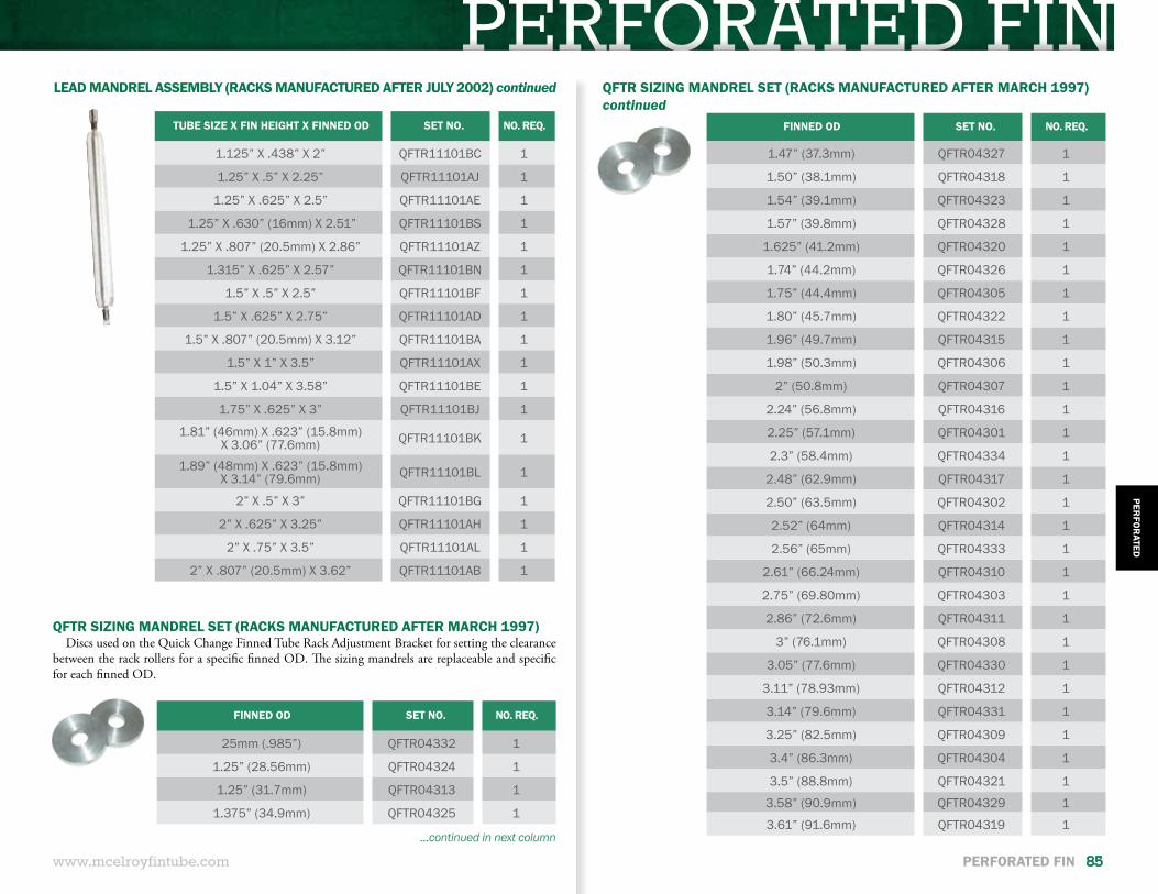
PERFORATED FIN
www.mcelroyfintube.com
PERFO
RATED
PERFORATED FIN 85
TUBE SIZE X FIN HEIGHT X FINNED OD SET NO. NO. REQ.
1.125” X .438” X 2” QFTR11101BC 1
1.25” X .5” X 2.25” QFTR11101AJ 1
1.25” X .625” X 2.5” QFTR11101AE 1
1.25” X .630” (16mm) X 2.51” QFTR11101BS 1
1.25” X .807” (20.5mm) X 2.86” QFTR11101AZ 1
1.315” X .625” X 2.57” QFTR11101BN 1
1.5” X .5” X 2.5” QFTR11101BF 1
1.5” X .625” X 2.75” QFTR11101AD 1
1.5” X .807” (20.5mm) X 3.12” QFTR11101BA 1
1.5” X 1” X 3.5” QFTR11101AX 1
1.5” X 1.04” X 3.58” QFTR11101BE 1
1.75” X .625” X 3” QFTR11101BJ 1
1.81” (46mm) X .623” (15.8mm) X 3.06” (77.6mm) QFTR11101BK 1
1.89” (48mm) X .623” (15.8mm) X 3.14” (79.6mm) QFTR11101BL 1
2” X .5” X 3” QFTR11101BG 1
2” X .625” X 3.25” QFTR11101AH 1
2” X .75” X 3.5” QFTR11101AL 1
2” X .807” (20.5mm) X 3.62” QFTR11101AB 1
FINNED OD SET NO. NO. REQ.
25mm (.985”) QFTR04332 1
1.25” (28.56mm) QFTR04324 1
1.25” (31.7mm) QFTR04313 1
1.375” (34.9mm) QFTR04325 1
QFTR SIZING MANDREL SET (RACKS MANUFACTURED AFTER MARCH 1997)Discs used on the Quick Change Finned Tube Rack Adjustment Bracket for setting the clearance
between the rack rollers for a specific finned OD. The sizing mandrels are replaceable and specific for each finned OD.
QFTR SIZING MANDREL SET (RACKS MANUFACTURED AFTER MARCH 1997)continued
FINNED OD SET NO. NO. REQ.
1.47” (37.3mm) QFTR04327 1
1.50” (38.1mm) QFTR04318 1
1.54” (39.1mm) QFTR04323 1
1.57” (39.8mm) QFTR04328 1
1.625” (41.2mm) QFTR04320 1
1.74” (44.2mm) QFTR04326 1
1.75” (44.4mm) QFTR04305 1
1.80” (45.7mm) QFTR04322 1
1.96” (49.7mm) QFTR04315 1
1.98” (50.3mm) QFTR04306 1
2” (50.8mm) QFTR04307 1
2.24” (56.8mm) QFTR04316 1
2.25” (57.1mm) QFTR04301 1
2.3” (58.4mm) QFTR04334 1
2.48” (62.9mm) QFTR04317 1
2.50” (63.5mm) QFTR04302 1
2.52” (64mm) QFTR04314 1
2.56” (65mm) QFTR04333 1
2.61” (66.24mm) QFTR04310 1
2.75” (69.80mm) QFTR04303 1
2.86” (72.6mm) QFTR04311 1
3” (76.1mm) QFTR04308 1
3.05” (77.6mm) QFTR04330 1
3.11” (78.93mm) QFTR04312 1
3.14” (79.6mm) QFTR04331 1
3.25” (82.5mm) QFTR04309 1
3.4” (86.3mm) QFTR04304 1
3.5” (88.8mm) QFTR04321 1
3.58” (90.9mm) QFTR04329 1
3.61” (91.6mm) QFTR04319 1...continued in next column
LEAD MANDREL ASSEMBLY (RACKS MANUFACTURED AFTER JULY 2002) continued
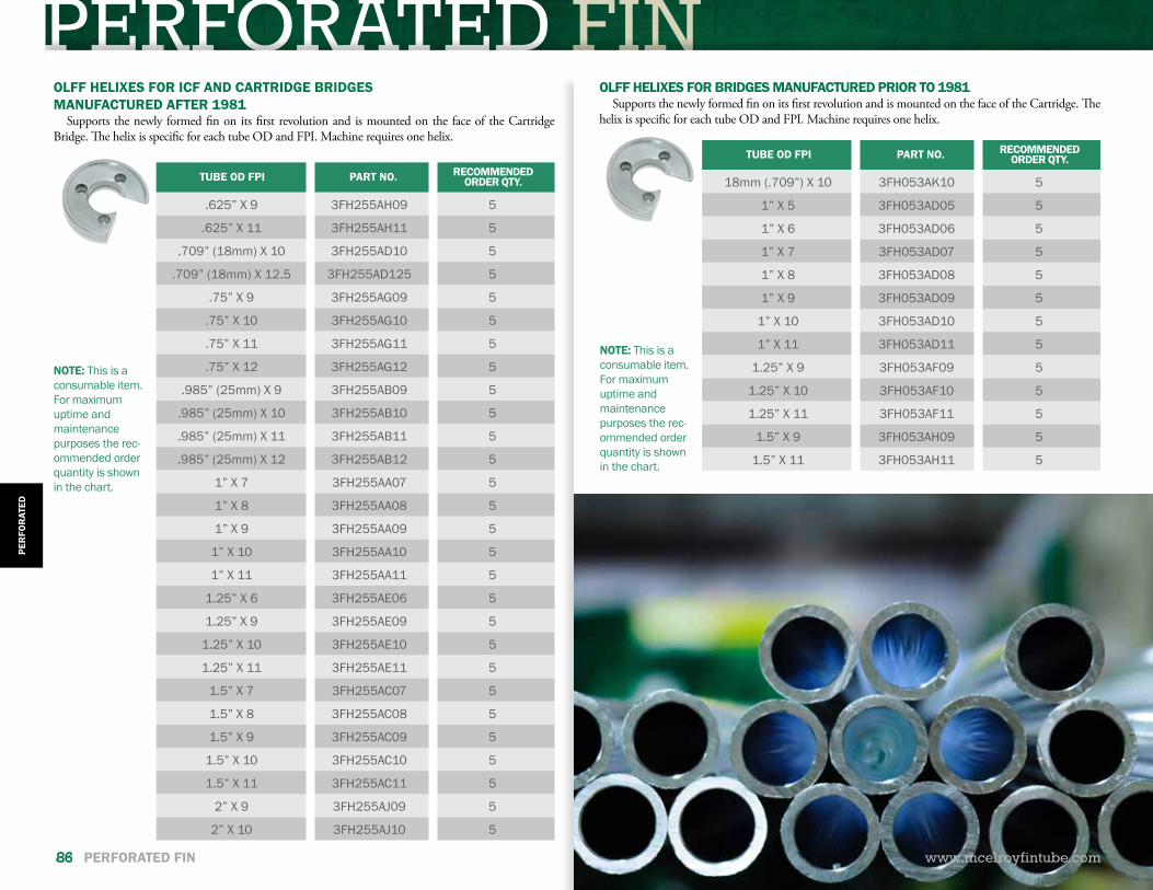
PERFORATED FINPE
RFO
RAT
ED
86 PERFORATED FIN
NOTE: This is a consumable item. For maximum uptime and maintenance purposes the rec-ommended order quantity is shown in the chart.
OLFF HELIXES FOR ICF AND CARTRIDGE BRIDGESMANUFACTURED AFTER 1981
Supports the newly formed fin on its first revolution and is mounted on the face of the Cartridge Bridge. The helix is specific for each tube OD and FPI. Machine requires one helix.
OLFF HELIXES FOR BRIDGES MANUFACTURED PRIOR TO 1981Supports the newly formed fin on its first revolution and is mounted on the face of the Cartridge. The
helix is specific for each tube OD and FPI. Machine requires one helix.
TUBE OD FPI PART NO. RECOMMENDED ORDER QTY.
18mm (.709”) X 10 3FH053AK10 5
1” X 5 3FH053AD05 5
1” X 6 3FH053AD06 5
1” X 7 3FH053AD07 5
1” X 8 3FH053AD08 5
1” X 9 3FH053AD09 5
1” X 10 3FH053AD10 5
1” X 11 3FH053AD11 5
1.25” X 9 3FH053AF09 5
1.25” X 10 3FH053AF10 5
1.25” X 11 3FH053AF11 5
1.5” X 9 3FH053AH09 5
1.5” X 11 3FH053AH11 5
NOTE: This is a consumable item. For maximum uptime and maintenance purposes the rec-ommended order quantity is shown in the chart.
TUBE OD FPI PART NO. RECOMMENDED ORDER QTY.
.625” X 9 3FH255AH09 5
.625” X 11 3FH255AH11 5
.709” (18mm) X 10 3FH255AD10 5
.709” (18mm) X 12.5 3FH255AD125 5
.75” X 9 3FH255AG09 5
.75” X 10 3FH255AG10 5
.75” X 11 3FH255AG11 5
.75” X 12 3FH255AG12 5
.985” (25mm) X 9 3FH255AB09 5
.985” (25mm) X 10 3FH255AB10 5
.985” (25mm) X 11 3FH255AB11 5
.985” (25mm) X 12 3FH255AB12 5
1” X 7 3FH255AA07 5
1” X 8 3FH255AA08 5
1” X 9 3FH255AA09 5
1” X 10 3FH255AA10 5
1” X 11 3FH255AA11 5
1.25” X 6 3FH255AE06 5
1.25” X 9 3FH255AE09 5
1.25” X 10 3FH255AE10 5
1.25” X 11 3FH255AE11 5
1.5” X 7 3FH255AC07 5
1.5” X 8 3FH255AC08 5
1.5” X 9 3FH255AC09 5
1.5” X 10 3FH255AC10 5
1.5” X 11 3FH255AC11 5
2” X 9 3FH255AJ09 5
2” X 10 3FH255AJ10 5
www.mcelroyfintube.com
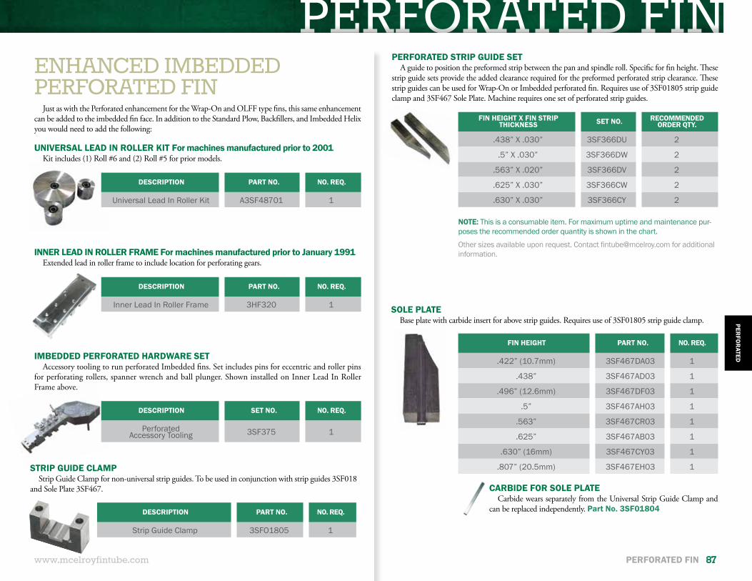
PERFORATED FIN
DESCRIPTION PART NO. NO. REQ.
Strip Guide Clamp 3SFO1805 1
STRIP GUIDE CLAMPStrip Guide Clamp for non-universal strip guides. To be used in conjunction with strip guides 3SF018
and Sole Plate 3SF467.
ENHANCED IMBEDDEDPERFORATED FIN
Just as with the Perforated enhancement for the Wrap-On and OLFF type fins, this same enhancement can be added to the imbedded fin face. In addition to the Standard Plow, Backfillers, and Imbedded Helix you would need to add the following:
UNIVERSAL LEAD IN ROLLER KIT For machines manufactured prior to 2001Kit includes (1) Roll #6 and (2) Roll #5 for prior models.
INNER LEAD IN ROLLER FRAME For machines manufactured prior to January 1991Extended lead in roller frame to include location for perforating gears.
DESCRIPTION PART NO. NO. REQ.
Universal Lead In Roller Kit A3SF48701 1
DESCRIPTION PART NO. NO. REQ.
Inner Lead In Roller Frame 3HF320 1
DESCRIPTION SET NO. NO. REQ.
Perforated Accessory Tooling 3SF375 1
IMBEDDED PERFORATED HARDWARE SETAccessory tooling to run perforated Imbedded fins. Set includes pins for eccentric and roller pins
for perforating rollers, spanner wrench and ball plunger. Shown installed on Inner Lead In Roller Frame above.
FIN HEIGHT PART NO. NO. REQ.
.422” (10.7mm) 3SF467DA03 1
.438” 3SF467AD03 1
.496” (12.6mm) 3SF467DF03 1
.5” 3SF467AH03 1
.563” 3SF467CR03 1
.625” 3SF467AB03 1
.630” (16mm) 3SF467CY03 1
.807” (20.5mm) 3SF467EH03 1
SOLE PLATEBase plate with carbide insert for above strip guides. Requires use of 3SF01805 strip guide clamp.
CARBIDE FOR SOLE PLATECarbide wears separately from the Universal Strip Guide Clamp and
can be replaced independently. Part No. 3SF01804
FIN HEIGHT X FIN STRIP THICKNESS SET NO. RECOMMENDED
ORDER QTY.
.438” X .030” 3SF366DU 2
.5” X .030” 3SF366DW 2
.563” X .020” 3SF366DV 2
.625” X .030” 3SF366CW 2
.630” X .030” 3SF366CY 2
PERFORATED STRIP GUIDE SETA guide to position the preformed strip between the pan and spindle roll. Specific for fin height. These
strip guide sets provide the added clearance required for the preformed perforated strip clearance. These strip guides can be used for Wrap-On or Imbedded perforated fin. Requires use of 3SF01805 strip guide clamp and 3SF467 Sole Plate. Machine requires one set of perforated strip guides.
Other sizes available upon request. Contact [email protected] for additional information.
NOTE: This is a consumable item. For maximum uptime and maintenance pur-poses the recommended order quantity is shown in the chart.
www.mcelroyfintube.com
PERFO
RATED
PERFORATED FIN 87
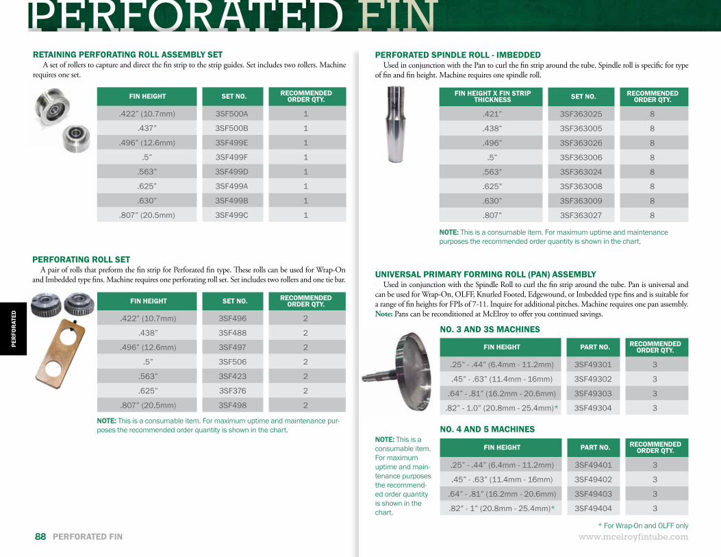
PERFORATED FIN
www.mcelroyfintube.com88 PERFORATED FIN
FIN HEIGHT SET NO. RECOMMENDED ORDER QTY.
.422” (10.7mm) 3SF500A 1
.437” 3SF500B 1
.496” (12.6mm) 3SF499E 1
.5” 3SF499F 1
.563” 3SF499D 1
.625” 3SF499A 1
.630” 3SF499B 1
.807” (20.5mm) 3SF499C 1
RETAINING PERFORATING ROLL ASSEMBLY SET A set of rollers to capture and direct the fin strip to the strip guides. Set includes two rollers. Machine
requires one set.
NOTE: This is a consumable item. For maximum uptime and maintenance pur-poses the recommended order quantity is shown in the chart.
FIN HEIGHT SET NO. RECOMMENDED ORDER QTY.
.422” (10.7mm) 3SF496 2
.438” 3SF488 2
.496” (12.6mm) 3SF497 2
.5” 3SF506 2
.563” 3SF423 2
.625” 3SF376 2
.807” (20.5mm) 3SF498 2
PERFORATING ROLL SETA pair of rolls that preform the fin strip for Perforated fin type. These rolls can be used for Wrap-On
and Imbedded type fins. Machine requires one perforating roll set. Set includes two rollers and one tie bar.
FIN HEIGHT X FIN STRIP THICKNESS SET NO. RECOMMENDED
ORDER QTY.
.421” 3SF363025 8
.438” 3SF363005 8
.496” 3SF363026 8
.5” 3SF363006 8
.563” 3SF363024 8
.625” 3SF363008 8
.630” 3SF363009 8
.807” 3SF363027 8
NOTE: This is a consumable item. For maximum uptime and maintenance purposes the recommended order quantity is shown in the chart.
PERFORATED SPINDLE ROLL - IMBEDDEDUsed in conjunction with the Pan to curl the fin strip around the tube. Spindle roll is specific for type
of fin and fin height. Machine requires one spindle roll.
NOTE: This is a consumable item. For maximum uptime and main-tenance purposes the recommend-ed order quantity is shown in the chart.
FIN HEIGHT PART NO. RECOMMENDED ORDER QTY.
.25” - .44” (6.4mm - 11.2mm) 3SF49301 3
.45” - .63” (11.4mm - 16mm) 3SF49302 3
.64” - .81” (16.2mm - 20.6mm) 3SF49303 3
.82” - 1.0” (20.8mm - 25.4mm)* 3SF49304 3
FIN HEIGHT PART NO. RECOMMENDED ORDER QTY.
.25” - .44” (6.4mm - 11.2mm) 3SF49401 3
.45” - .63” (11.4mm - 16mm) 3SF49402 3
.64” - .81” (16.2mm - 20.6mm) 3SF49403 3
.82” - 1” (20.8mm - 25.4mm)* 3SF49404 3
UNIVERSAL PRIMARY FORMING ROLL (PAN) ASSEMBLYUsed in conjunction with the Spindle Roll to curl the fin strip around the tube. Pan is universal and
can be used for Wrap-On, OLFF, Knurled Footed, Edgewound, or Imbedded type fins and is suitable for a range of fin heights for FPIs of 7-11. Inquire for additional pitches. Machine requires one pan assembly. Note: Pans can be reconditioned at McElroy to offer you continued savings.
NO. 3 AND 3S MACHINES
NO. 4 AND 5 MACHINES
* For Wrap-On and OLFF only
PER
FOR
ATED
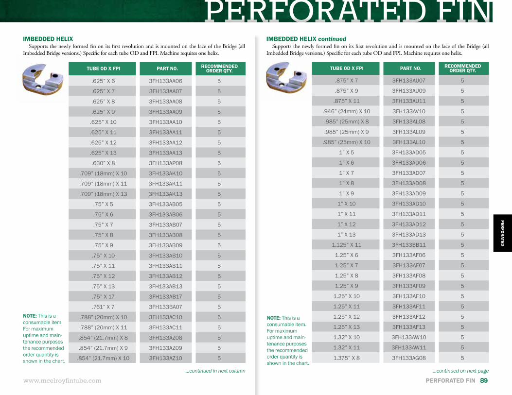
PERFORATED FIN
www.mcelroyfintube.com
PERFO
RATED
PERFORATED FIN 89
TUBE OD X FPI PART NO. RECOMMENDED ORDER QTY.
.625” X 6 3FH133AA06 5
.625” X 7 3FH133AA07 5
.625” X 8 3FH133AA08 5
.625” X 9 3FH133AA09 5
.625” X 10 3FH133AA10 5
.625” X 11 3FH133AA11 5
.625” X 12 3FH133AA12 5
.625” X 13 3FH133AA13 5
.630” X 8 3FH133AP08 5
.709” (18mm) X 10 3FH133AK10 5
.709” (18mm) X 11 3FH133AK11 5
.709” (18mm) X 13 3FH133AK13 5
.75” X 5 3FH133AB05 5
.75” X 6 3FH133AB06 5
.75” X 7 3FH133AB07 5
.75” X 8 3FH133AB08 5
.75” X 9 3FH133AB09 5
.75” X 10 3FH133AB10 5
.75” X 11 3FH133AB11 5
.75” X 12 3FH133AB12 5
.75” X 13 3FH133AB13 5
.75” X 17 3FH133AB17 5
.761” X 7 3FH133BA07 5
.788” (20mm) X 10 3FH133AC10 5
.788” (20mm) X 11 3FH133AC11 5
.854” (21.7mm) X 8 3FH133AZ08 5
.854” (21.7mm) X 9 3FH133AZ09 5
.854” (21.7mm) X 10 3FH133AZ10 5
IMBEDDED HELIXSupports the newly formed fin on its first revolution and is mounted on the face of the Bridge (all
Imbedded Bridge versions.) Specific for each tube OD and FPI. Machine requires one helix.
NOTE: This is a consumable item. For maximum uptime and main-tenance purposes the recommended order quantity is shown in the chart.
...continued in next column
TUBE OD X FPI PART NO. RECOMMENDED ORDER QTY.
.875” X 7 3FH133AU07 5
.875” X 9 3FH133AU09 5
.875” X 11 3FH133AU11 5
.946” (24mm) X 10 3FH133AV10 5
.985” (25mm) X 8 3FH133AL08 5
.985” (25mm) X 9 3FH133AL09 5
.985” (25mm) X 10 3FH133AL10 5
1” X 5 3FH133AD05 5
1” X 6 3FH133AD06 5
1” X 7 3FH133AD07 5
1” X 8 3FH133AD08 5
1” X 9 3FH133AD09 5
1” X 10 3FH133AD10 5
1” X 11 3FH133AD11 5
1” X 12 3FH133AD12 5
1” X 13 3FH133AD13 5
1.125” X 11 3FH133BB11 5
1.25” X 6 3FH133AF06 5
1.25” X 7 3FH133AF07 5
1.25” X 8 3FH133AF08 5
1.25” X 9 3FH133AF09 5
1.25” X 10 3FH133AF10 5
1.25” X 11 3FH133AF11 5
1.25” X 12 3FH133AF12 5
1.25” X 13 3FH133AF13 5
1.32” X 10 3FH133AW10 5
1.32” X 11 3FH133AW11 5
1.375” X 8 3FH133AG08 5
IMBEDDED HELIX continuedSupports the newly formed fin on its first revolution and is mounted on the face of the Bridge (all
Imbedded Bridge versions.) Specific for each tube OD and FPI. Machine requires one helix.
NOTE: This is a consumable item. For maximum uptime and main-tenance purposes the recommended order quantity is shown in the chart.
...continued on next page
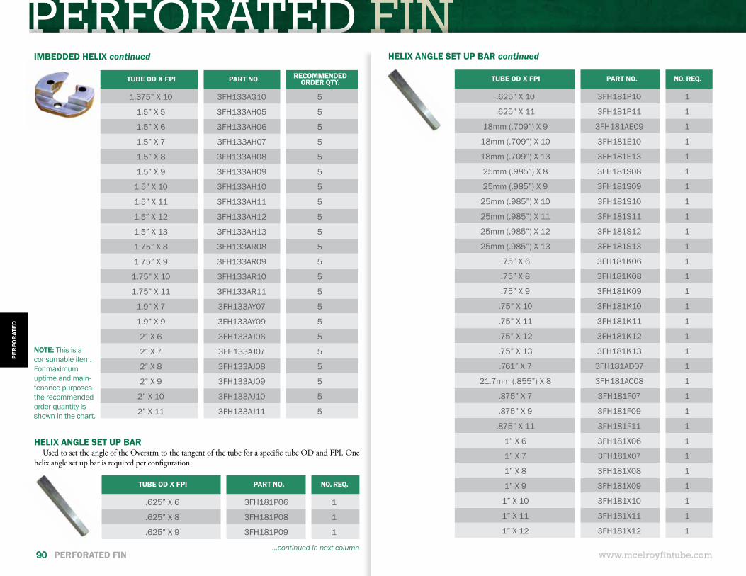
PERFORATED FIN
www.mcelroyfintube.com
PER
FOR
ATED
90 PERFORATED FIN
IMBEDDED HELIX continued
NOTE: This is a consumable item. For maximum uptime and main-tenance purposes the recommended order quantity is shown in the chart.
TUBE OD X FPI PART NO. RECOMMENDED ORDER QTY.
1.375” X 10 3FH133AG10 5
1.5” X 5 3FH133AH05 5
1.5” X 6 3FH133AH06 5
1.5” X 7 3FH133AH07 5
1.5” X 8 3FH133AH08 5
1.5” X 9 3FH133AH09 5
1.5” X 10 3FH133AH10 5
1.5” X 11 3FH133AH11 5
1.5” X 12 3FH133AH12 5
1.5” X 13 3FH133AH13 5
1.75” X 8 3FH133AR08 5
1.75” X 9 3FH133AR09 5
1.75” X 10 3FH133AR10 5
1.75” X 11 3FH133AR11 5
1.9” X 7 3FH133AY07 5
1.9” X 9 3FH133AY09 5
2” X 6 3FH133AJ06 5
2” X 7 3FH133AJ07 5
2” X 8 3FH133AJ08 5
2” X 9 3FH133AJ09 5
2” X 10 3FH133AJ10 5
2” X 11 3FH133AJ11 5
TUBE OD X FPI PART NO. NO. REQ.
.625” X 6 3FH181P06 1
.625” X 8 3FH181P08 1
.625” X 9 3FH181P09 1
HELIX ANGLE SET UP BARUsed to set the angle of the Overarm to the tangent of the tube for a specific tube OD and FPI. One
helix angle set up bar is required per configuration.
...continued in next column
HELIX ANGLE SET UP BAR continued
TUBE OD X FPI PART NO. NO. REQ.
.625” X 10 3FH181P10 1
.625” X 11 3FH181P11 1
18mm (.709”) X 9 3FH181AE09 1
18mm (.709”) X 10 3FH181E10 1
18mm (.709”) X 13 3FH181E13 1
25mm (.985”) X 8 3FH181S08 1
25mm (.985”) X 9 3FH181S09 1
25mm (.985”) X 10 3FH181S10 1
25mm (.985”) X 11 3FH181S11 1
25mm (.985”) X 12 3FH181S12 1
25mm (.985”) X 13 3FH181S13 1
.75” X 6 3FH181K06 1
.75” X 8 3FH181K08 1
.75” X 9 3FH181K09 1
.75” X 10 3FH181K10 1
.75” X 11 3FH181K11 1
.75” X 12 3FH181K12 1
.75” X 13 3FH181K13 1
.761” X 7 3FH181AD07 1
21.7mm (.855”) X 8 3FH181AC08 1
.875” X 7 3FH181F07 1
.875” X 9 3FH181F09 1
.875” X 11 3FH181F11 1
1” X 6 3FH181X06 1
1” X 7 3FH181X07 1
1” X 8 3FH181X08 1
1” X 9 3FH181X09 1
1” X 10 3FH181X10 1
1” X 11 3FH181X11 1
1” X 12 3FH181X12 1
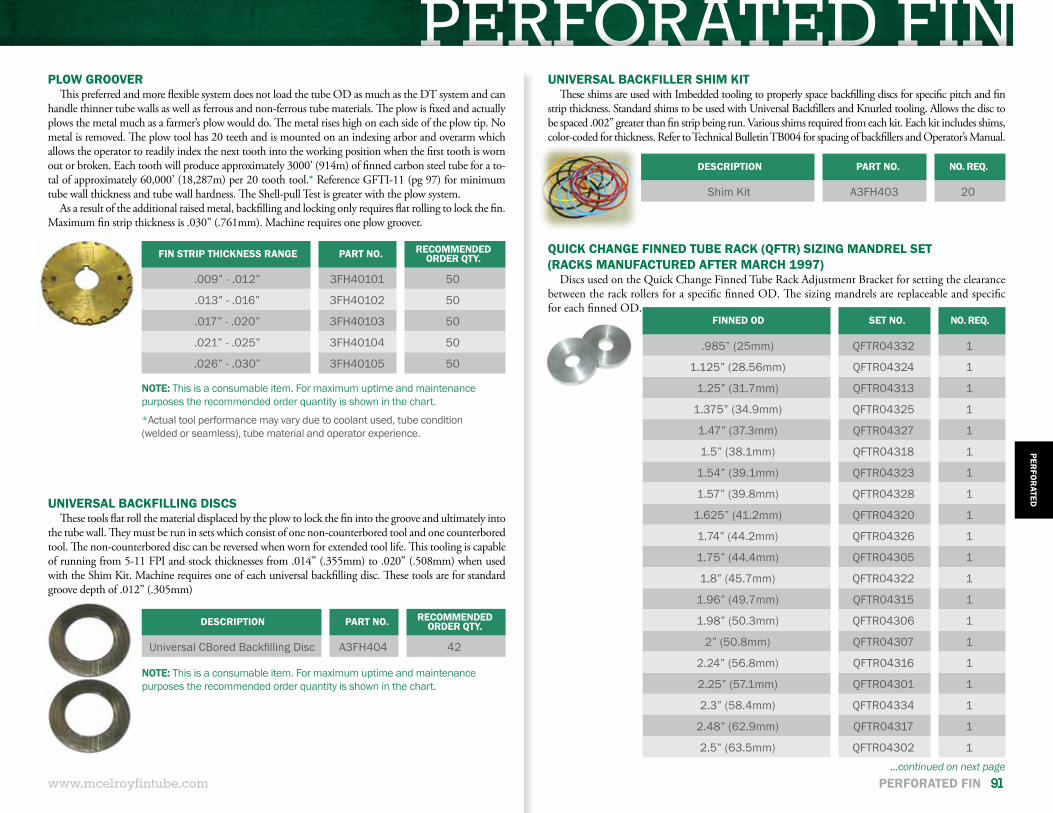
PERFORATED FINPLOW GROOVER
This preferred and more flexible system does not load the tube OD as much as the DT system and can handle thinner tube walls as well as ferrous and non-ferrous tube materials. The plow is fixed and actually plows the metal much as a farmer’s plow would do. The metal rises high on each side of the plow tip. No metal is removed. The plow tool has 20 teeth and is mounted on an indexing arbor and overarm which allows the operator to readily index the next tooth into the working position when the first tooth is worn out or broken. Each tooth will produce approximately 3000’ (914m) of finned carbon steel tube for a to-tal of approximately 60,000’ (18,287m) per 20 tooth tool.* Reference GFTI-11 (pg 97) for minimum tube wall thickness and tube wall hardness. The Shell-pull Test is greater with the plow system.
As a result of the additional raised metal, backfilling and locking only requires flat rolling to lock the fin. Maximum fin strip thickness is .030” (.761mm). Machine requires one plow groover.
FIN STRIP THICKNESS RANGE PART NO. RECOMMENDED ORDER QTY.
.009” - .012” 3FH40101 50
.013” - .016” 3FH40102 50
.017” - .020” 3FH40103 50
.021” - .025” 3FH40104 50
.026” - .030” 3FH40105 50
NOTE: This is a consumable item. For maximum uptime and maintenance purposes the recommended order quantity is shown in the chart.
*Actual tool performance may vary due to coolant used, tube condition (welded or seamless), tube material and operator experience.
UNIVERSAL BACKFILLING DISCSThese tools flat roll the material displaced by the plow to lock the fin into the groove and ultimately into
the tube wall. They must be run in sets which consist of one non-counterbored tool and one counterbored tool. The non-counterbored disc can be reversed when worn for extended tool life. This tooling is capable of running from 5-11 FPI and stock thicknesses from .014” (.355mm) to .020” (.508mm) when used with the Shim Kit. Machine requires one of each universal backfilling disc. These tools are for standard groove depth of .012” (.305mm)
DESCRIPTION PART NO. NO. REQ.
Shim Kit A3FH403 20
UNIVERSAL BACKFILLER SHIM KITThese shims are used with Imbedded tooling to properly space backfilling discs for specific pitch and fin
strip thickness. Standard shims to be used with Universal Backfillers and Knurled tooling. Allows the disc to be spaced .002” greater than fin strip being run. Various shims required from each kit. Each kit includes shims, color-coded for thickness. Refer to Technical Bulletin TB004 for spacing of backfillers and Operator’s Manual.
FINNED OD SET NO. NO. REQ.
.985” (25mm) QFTR04332 1
1.125” (28.56mm) QFTR04324 1
1.25” (31.7mm) QFTR04313 1
1.375” (34.9mm) QFTR04325 1
1.47” (37.3mm) QFTR04327 1
1.5” (38.1mm) QFTR04318 1
1.54” (39.1mm) QFTR04323 1
1.57” (39.8mm) QFTR04328 1
1.625” (41.2mm) QFTR04320 1
1.74” (44.2mm) QFTR04326 1
1.75” (44.4mm) QFTR04305 1
1.8” (45.7mm) QFTR04322 1
1.96” (49.7mm) QFTR04315 1
1.98” (50.3mm) QFTR04306 1
2” (50.8mm) QFTR04307 1
2.24” (56.8mm) QFTR04316 1
2.25” (57.1mm) QFTR04301 1
2.3” (58.4mm) QFTR04334 1
2.48” (62.9mm) QFTR04317 1
2.5” (63.5mm) QFTR04302 1
QUICK CHANGE FINNED TUBE RACK (QFTR) SIZING MANDREL SET(RACKS MANUFACTURED AFTER MARCH 1997)
Discs used on the Quick Change Finned Tube Rack Adjustment Bracket for setting the clearance between the rack rollers for a specific finned OD. The sizing mandrels are replaceable and specific for each finned OD.
...continued on next page
DESCRIPTION PART NO. RECOMMENDED ORDER QTY.
Universal CBored Backfilling Disc A3FH404 42
NOTE: This is a consumable item. For maximum uptime and maintenance purposes the recommended order quantity is shown in the chart.
www.mcelroyfintube.com
PERFO
RATED
PERFORATED FIN 91
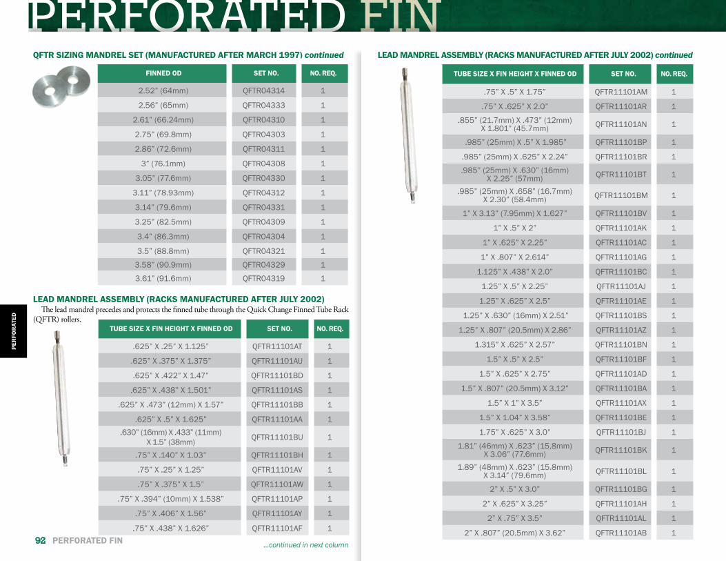
PERFORATED FINQFTR SIZING MANDREL SET (MANUFACTURED AFTER MARCH 1997) continued
FINNED OD SET NO. NO. REQ.
2.52” (64mm) QFTR04314 1
2.56” (65mm) QFTR04333 1
2.61” (66.24mm) QFTR04310 1
2.75” (69.8mm) QFTR04303 1
2.86” (72.6mm) QFTR04311 1
3” (76.1mm) QFTR04308 1
3.05” (77.6mm) QFTR04330 1
3.11” (78.93mm) QFTR04312 1
3.14” (79.6mm) QFTR04331 1
3.25” (82.5mm) QFTR04309 1
3.4” (86.3mm) QFTR04304 1
3.5” (88.8mm) QFTR04321 1
3.58” (90.9mm) QFTR04329 1
3.61” (91.6mm) QFTR04319 1
LEAD MANDREL ASSEMBLY (RACKS MANUFACTURED AFTER JULY 2002)The lead mandrel precedes and protects the finned tube through the Quick Change Finned Tube Rack
(QFTR) rollers.TUBE SIZE X FIN HEIGHT X FINNED OD SET NO. NO. REQ.
.625” X .25” X 1.125” QFTR11101AT 1
.625” X .375” X 1.375” QFTR11101AU 1
.625” X .422” X 1.47” QFTR11101BD 1
.625” X .438” X 1.501” QFTR11101AS 1
.625” X .473” (12mm) X 1.57” QFTR11101BB 1
.625” X .5” X 1.625” QFTR11101AA 1.630” (16mm) X .433” (11mm)
X 1.5” (38mm) QFTR11101BU 1
.75” X .140” X 1.03” QFTR11101BH 1
.75” X .25” X 1.25” QFTR11101AV 1
.75” X .375” X 1.5” QFTR11101AW 1
.75” X .394” (10mm) X 1.538” QFTR11101AP 1
.75” X .406” X 1.56” QFTR11101AY 1
.75” X .438” X 1.626” QFTR11101AF 1
...continued in next column
LEAD MANDREL ASSEMBLY (RACKS MANUFACTURED AFTER JULY 2002) continued
TUBE SIZE X FIN HEIGHT X FINNED OD SET NO. NO. REQ.
.75” X .5” X 1.75” QFTR11101AM 1
.75” X .625” X 2.0” QFTR11101AR 1
.855” (21.7mm) X .473” (12mm) X 1.801” (45.7mm) QFTR11101AN 1
.985” (25mm) X .5” X 1.985” QFTR11101BP 1
.985” (25mm) X .625” X 2.24” QFTR11101BR 1
.985” (25mm) X .630” (16mm) X 2.25” (57mm) QFTR11101BT 1
.985” (25mm) X .658” (16.7mm) X 2.30” (58.4mm) QFTR11101BM 1
1” X 3.13” (7.95mm) X 1.627” QFTR11101BV 1
1” X .5” X 2” QFTR11101AK 1
1” X .625” X 2.25” QFTR11101AC 1
1” X .807” X 2.614” QFTR11101AG 1
1.125” X .438” X 2.0” QFTR11101BC 1
1.25” X .5” X 2.25” QFTR11101AJ 1
1.25” X .625” X 2.5” QFTR11101AE 1
1.25” X .630” (16mm) X 2.51” QFTR11101BS 1
1.25” X .807” (20.5mm) X 2.86” QFTR11101AZ 1
1.315” X .625” X 2.57” QFTR11101BN 1
1.5” X .5” X 2.5” QFTR11101BF 1
1.5” X .625” X 2.75” QFTR11101AD 1
1.5” X .807” (20.5mm) X 3.12” QFTR11101BA 1
1.5” X 1” X 3.5” QFTR11101AX 1
1.5” X 1.04” X 3.58” QFTR11101BE 1
1.75” X .625” X 3.0” QFTR11101BJ 1
1.81” (46mm) X .623” (15.8mm) X 3.06” (77.6mm) QFTR11101BK 1
1.89” (48mm) X .623” (15.8mm) X 3.14” (79.6mm) QFTR11101BL 1
2” X .5” X 3.0” QFTR11101BG 1
2” X .625” X 3.25” QFTR11101AH 1
2” X .75” X 3.5” QFTR11101AL 1
2” X .807” (20.5mm) X 3.62” QFTR11101AB 1
PER
FOR
ATED
92 PERFORATED FIN

REFERENCE GUIDE APPLIEDIMBEDDED FIN
APPLIED MACHINEREFERENCE GUIDE
www.mcelroyfintube.com
APPLIEDR
EFEREN
CE
APPLIED REFERENCE GUIDE 93
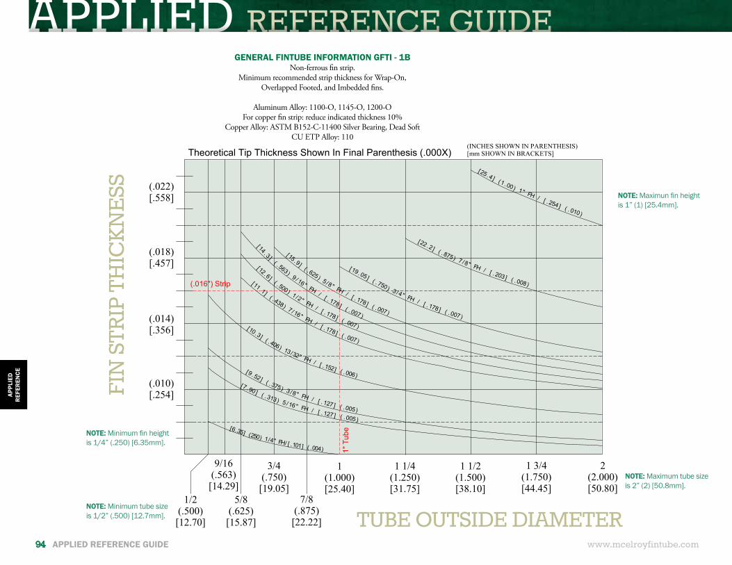
APPLIED REFERENCE GUIDE
www.mcelroyfintube.com
APPL
IED
REF
EREN
CE
94 APPLIED REFERENCE GUIDE
(.022)[.558]
(.018)[.457]
(.014)[.356]
(.010)[.254]
Theoretical Tip Thickness Shown In Final Parenthesis (.000X)
5/8(.625)[15.87]
9/16(.563)[14.29]
3/4(.750)
[19.05]7/8
(.875)[22.22]
1(1.000)[25.40]
1 1/4(1.250)[31.75]
1 1/2(1.500)[38.10]
1 3/4(1.750)[44.45]
2(2.000)[50.80]
(INCHES SHOWN IN PARENTHESIS)[mm SHOWN IN BRACKETS]
[6.35] (250) 1/4" FH/ [ .101] ( .004)
[7 .90 ] ( .313) 5 /16" FH / [ .127 ] ( .005)
[9 .52 ] ( .375) 3 /8" FH / [ .127 ] ( .005)
[10.3] ( .406) 13/32" FH / [ .152] ( .006)
[11 .1 ] ( . 438) 7 /16" FH / [ .178 ] ( .007)
[12 .6 ] ( . 500) 1 /2" FH / [ .178 ] ( .007)
[ 14 . 3 ]( . 563) 9 / 16" FH
/ [ . 178 ] ( . 007)
[15 .9 ] ( .625) 5 /8" FH / [ .178 ] ( .007)
[19 .05 ] ( .750) 3 /4" FH / [ .178 ] ( . 007)
[25 .4 ] (1 .00) 1" FH / [ .254 ] ( .010)
[22 .2 ] ( .875) 7 /8" FH / [ . 203 ] ( .008)(.016") Strip
1" T
ube
1/2(.500)[12.70] TUBE OUTSIDE DIAMETER
GENERAL FINTUBE INFORMATION GFTI - 1BNon-ferrous fin strip.
Minimum recommended strip thickness for Wrap-On, Overlapped Footed, and Imbedded fins.
Aluminum Alloy: 1100-O, 1145-O, 1200-OFor copper fin strip: reduce indicated thickness 10%
Copper Alloy: ASTM B152-C-11400 Silver Bearing, Dead SoftCU ETP Alloy: 110
NOTE: Maximum tube size is 2” (2) [50.8mm].
NOTE: Maximun fin height is 1” (1) [25.4mm].
FIN
STR
IP T
HIC
KN
ESS
NOTE: Minimum tube size is 1/2” (.500) [12.7mm].
NOTE: Minimum fin height is 1/4” (.250) [6.35mm].
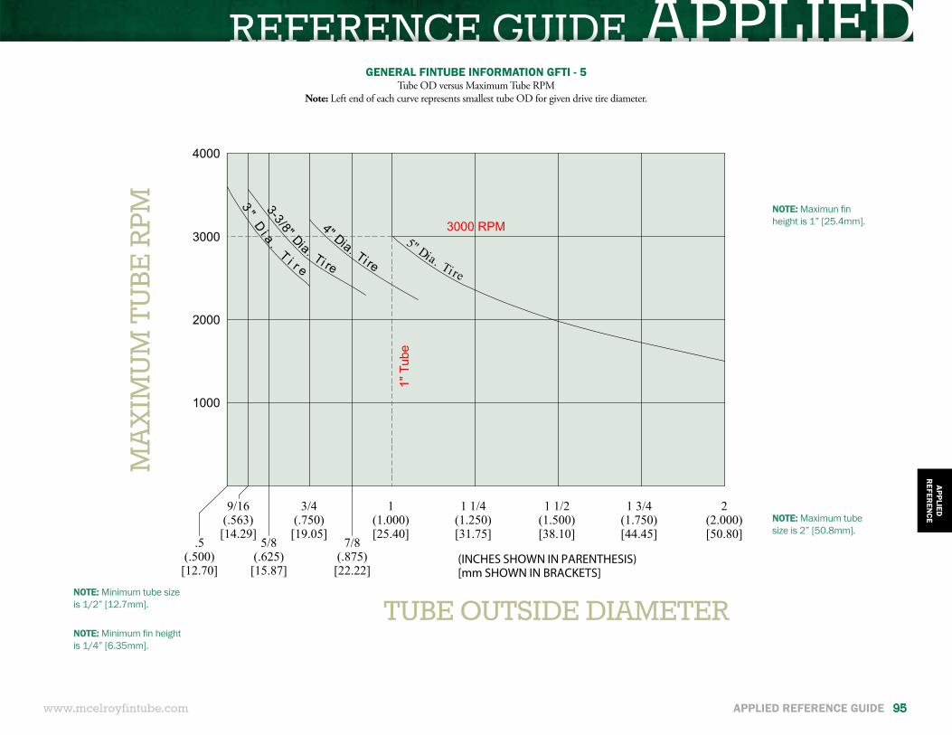
REFERENCE GUIDE APPLIED
www.mcelroyfintube.com
APPLIEDR
EFEREN
CE
APPLIED REFERENCE GUIDE 95
9/16(.563)[14.29]
3/4(.750)[19.05]
7/8(.875)[22.22]
5/8(.625)[15.87]
2(2.000)[50.80]
(INCHES SHOWN IN PARENTHESIS)[mm SHOWN IN BRACKETS]
1(1.000)[25.40]
1 1/4(1.250)[31.75]
1 1/2(1.500)[38.10]
1 3/4(1.750)[44.45]
1000
4000
3000
2000
3000 RPM
1" T
ube
5" Dia. Ti re
4" Dia. Ti re
3-3/8" Dia. Ti re
3 "D
i a .
T i r e
.5(.500)[12.70]
NOTE: Maximum tube size is 2” [50.8mm].
NOTE: Maximun fin height is 1” [25.4mm].
GENERAL FINTUBE INFORMATION GFTI - 5Tube OD versus Maximum Tube RPM
Note: Left end of each curve represents smallest tube OD for given drive tire diameter.
MA
XIM
UM
TU
BE R
PM
TUBE OUTSIDE DIAMETERNOTE: Minimum tube size is 1/2” [12.7mm].
NOTE: Minimum fin height is 1/4” [6.35mm].
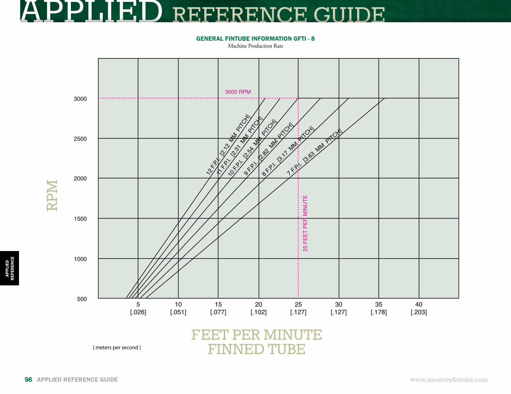
APPLIED REFERENCE GUIDE
[ meters per second ]
3000
2500
2000
1500
1000
5005
[.026]10
[.051]15
[.077]20
[.102]25
[.127]30
[.127]35
[.178]40
[.203]
12 F.
P.I. [
2.12
MM PIT
CH]
11 F.
P.I. [
2.31
MM PITC
H]
10 F.
P.I. [
2.54
MM PITC
H]
9 F.P.
I. [2.
82 M
M PITC
H]
8 F.P.
I. [3.
17 M
M PITCH]
7 F.P.I.
[3.63 MM P
ITCH]
3000 RPM
25 F
EET
PER
MIN
UTE
GENERAL FINTUBE INFORMATION GFTI - 8Machine Production Rate
FEET PER MINUTEFINNED TUBE
RPM
www.mcelroyfintube.com
APPL
IED
REF
EREN
CE
96 APPLIED REFERENCE GUIDE
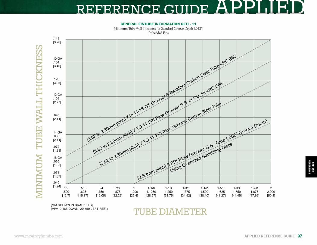
REFERENCE GUIDE APPLIED.149[3.78]
10 GA.134[3.40]
12 GA.109[2.77]
14 GA.083[2.11]
16 GA.065[1.65]
.120[3.05]
.095[2.41]
.072[1.83]
.054[1.37]
.049[1.24] 1/2
.500[12.7]
5/8.625
[15.87]
3/4.750
[19.05]
7/8.875
[22.22]
11.000[25.4]
1-1/81.1250[28.57]
1-1/41.250
[31.75]
1-3/81.375
[34.92]
1-1/21.500
[38.10]
1-5/81.625
[41.27]
1-3/41.750
[44.45]
1-7/81.875
[47.62]
22.000[50.8]
[MM SHOWN IN BRACKETS]
[3.62 to 2.30mm pitch] 7 to 11-18 DT Groover Backfiller Carbon Steel Tube RC B62
[3.62 to 2.30mm pitch] 7 TO 11 FI lo
Groover S.S. or CU. NI RC B84
[2.82mm pitch] 9 F I lo Groover S.S. Tube (.008 Groove Depth)
[3.62 to 2.30mm pitch] 7 TO 11 FI lo
Groover Carbon Steel Tube
Using Oversized Backfillin
g Discs
GENERAL FINTUBE INFORMATION GFTI - 11Minimum Tube Wall Thickness for Standard Groove Depth (.012”)
Imbedded Fins
MIN
IMU
M T
UBE
WA
LL T
HIC
KN
ESS
TUBE DIAMETER
www.mcelroyfintube.com
APPLIEDR
EFEREN
CE
APPLIED REFERENCE GUIDE 97
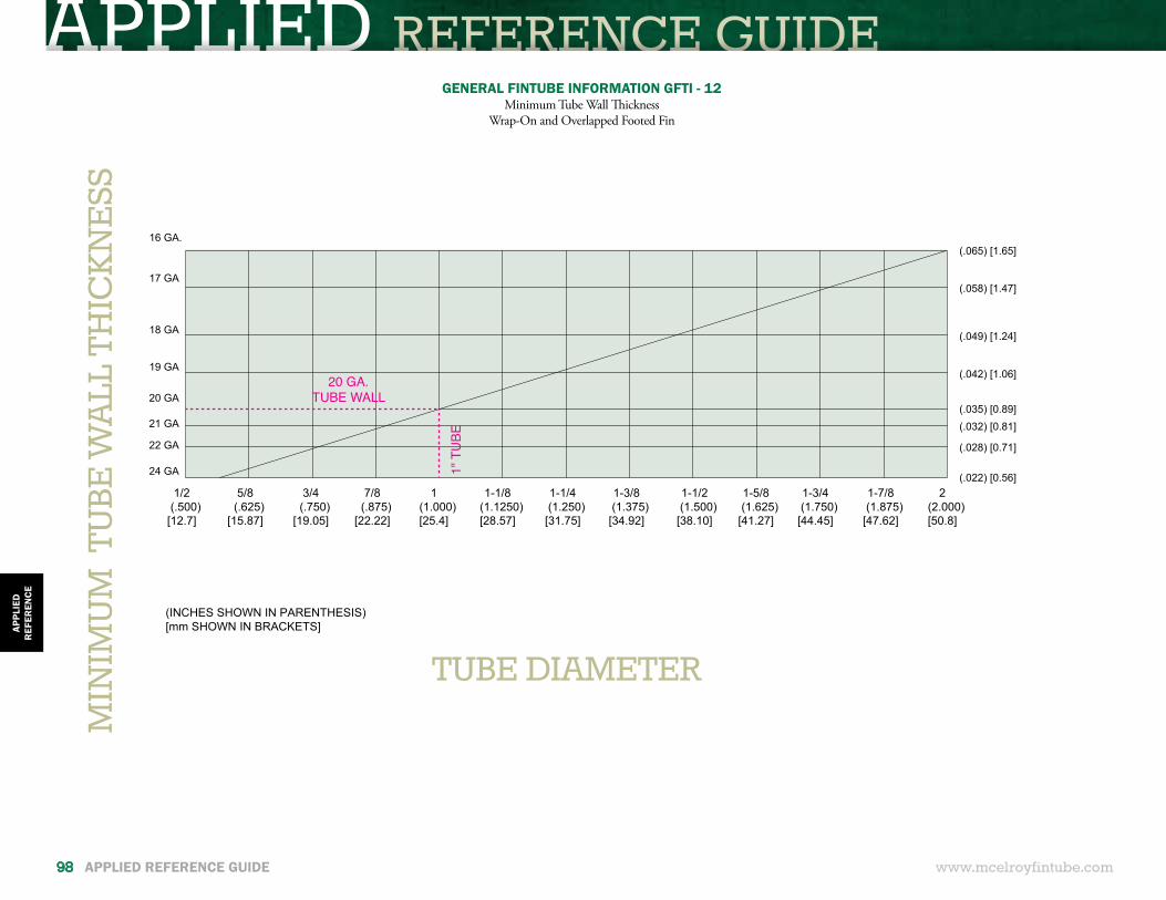
APPLIED REFERENCE GUIDE
(INCHES SHOWN IN PARENTHESIS)[mm SHOWN IN BRACKETS]
1/2(.500)
[12.7]
5/8(.625)
[15.87]
3/4(.750)
[19.05]
7/8(.875)
[22.22]
1(1.000)[25.4]
1-1/8(1.1250)[28.57]
1-1/4(1.250)[31.75]
1-3/8(1.375)[34.92]
1-1/2(1.500)
[38.10]
1-5/8(1.625)
[41.27]
1-3/4(1.750)[44.45]
1-7/8(1.875)
[47.62]
2(2.000)[50.8]
16 GA.
17 GA
18 GA
19 GA
20 GA
21 GA
24 GA
22 GA
(.065) [1.65]
(.058) [1.47]
(.049) [1.24]
(.042) [1.06]
(.035) [0.89](.032) [0.81]
(.028) [0.71]
(.022) [0.56]
20 GA.TUBE WALL
1" T
UBE
GENERAL FINTUBE INFORMATION GFTI - 12Minimum Tube Wall Thickness
Wrap-On and Overlapped Footed FinM
INIM
UM
TU
BE W
ALL
TH
ICK
NE
SS
TUBE DIAMETER
www.mcelroyfintube.com
APPL
IED
REF
EREN
CE
98 APPLIED REFERENCE GUIDE
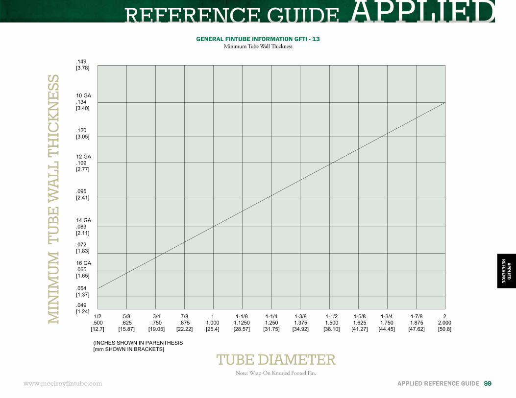
REFERENCE GUIDE APPLIED
(INCHES SHOWN IN PARENTHESIS[mm SHOWN IN BRACKETS]
.149[3.78]
10 GA.134[3.40]
12 GA.109[2.77]
14 GA.083[2.11]
16 GA.065[1.65]
.120[3.05]
.095[2.41]
.072[1.83]
.054[1.37]
.049[1.24]
1/2.500
[12.7]
5/8.625
[15.87]
3/4.750
[19.05]
7/8.875
[22.22]
11.000[25.4]
1-1/81.1250[28.57]
1-1/41.250
[31.75]
1-3/81.375
[34.92]
1-1/21.500
[38.10]
1-5/81.625
[41.27]
1-3/41.750
[44.45]
1-7/81.875
[47.62]
22.000[50.8]
GENERAL FINTUBE INFORMATION GFTI - 13Minimum Tube Wall Thickness
MIN
IMU
M T
UBE
WA
LL T
HIC
KN
ESS
TUBE DIAMETERNote: Wrap-On Knurled Footed Fin.
www.mcelroyfintube.com
APPLIEDR
EFEREN
CE
APPLIED REFERENCE GUIDE 99
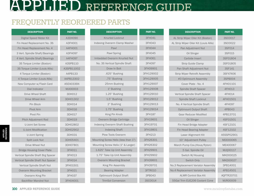
APPLIED REFERENCE GUIDE
DESCRIPTION PART NO.
Knurled Locknut 3FH041
Indexing Overarm Clamp Washer 3FH043
Pawl 3FH044
Pawl Spring 3FH045
Imbedded Overarm Knurled Nut 3FH061
No. 3S Vertical Spindle Shaft 3FH097
Draw In Bolt 3FH09901
.625” Bushing 3FH129002
.75” Bushing 3FH129005
25mm Bushing 3FH129007
1" Bushing 3FH129008
1.25” Bushing 3FH129010
1.5” Bushing 3FH129012
2” Bushing 3FH129013
1.75” Bushing 3FH129014
King Pin Knob 3FH187
Overarm Bridge Cartridge 3FH19601
Indexing Overarm Shaft Bushing 3FH19701
Indexing Shaft 3FH19801
Plow Tools Overarm 3FH213
Mounting Screw Helix (less than 1") 3FH26301
Mounting Screw Helix (1" & Larger) 3FH26302
1.625” Take Up Unit Assembly 3FH29901
1.75” Take Up Unit Assembly 3FH29902
Overarm Mounting Bracket 3FH39601
King Pin Assembly 3FH39701
Bearing Adapter 3FTR010
Optimount Output Shaft 3PB043
TrimSol Conversion 3SCO014
www.mcelroyfintube.com
APPL
IED
REF
EREN
CE
100 APPLIED REFERENCE GUIDE
FREQUENTLY REORDERED PARTSDESCRIPTION PART NO.
Digital Speed Meter Kit A3DH090
Fin Head Replacement No. 3S A3FH001
Fin Head Replacement No. 4 A4FH001
3 Vert. Spindle Shaft/Bearings A3FH097
4 Vert. Spindle Shaft/Bearings A4FH097
3S Torque Limiter (Boston) A3SPB110
3S Torque Limiter (Louis Allis) A3SPB11002
4 Torque Limiter (Boston) A4PB133
4 Torque Limiter (Louis Allis) A4PB13302
New Computer w/Flash Card A5EA033SN
Dial Indicator MJI00003
Drive Wheel Shaft 3DH012
Drive Wheel Arm 3DH01302
Pin Block 3DH014
Pivot Arm 3DH016
Pivot Pin 3DH017
Pitch Adjustment Rod 3DH019
U-Joint Set Screw 3DH02802
U-Joint Modification 3DH02902
U-Joint Spring 3DH031
Split Lock Nut 3DH05401
Drive Wheel Nut 3DH07801
Bridge Housing Cover Plate 3FH011
Vertical Spindle Shaft Brg Spacer 3FH013
Vertical Spindle Shaft Nut Spacer 3FH014
Vertical Spindle Shaft Nut 3FH01501
Overarm Mounting Bracket 3FH021
Overarm King Pin 3FH037
Backfiller Mandrel Nut 3FH04001
DESCRIPTION PART NO.
AL Strip Wiper Oiler Kit (Boston) 3SCO017
AL Strip Wiper Oiler Kit (Louis Allis) 3SCO022
Pan Adjustment Nut 3SF014
Oil Slinger 3SF015
Carbide Insert 3SF01804
Strip Guide Clamp 3SF01805
Pan Shaft Adjustment Nut 3SF141
Strip Wiper Retrofit Assembly 3SF47406
#3 Optimount Assembly 3SPB004
Cover Plate - No. 4 4FH01101
Spindle Shaft Spacer 4FH013
Vertical Spindle Shaft Spacer 4FH014
Spindle Shaft Locknut 4FH01501
No. 4 Vertical Spindle Shaft 4FH097
Optimount Output Shaft 4PB043
Gear Reducer Modified 4PB13701
Oil Slinger 4SF01501
Fin Head Bridge Adapter 4SF12101
Fin Head Bearing Adapter 4SF12102
Laser Alignment Kit A5SSP02901
10” Adjustment Pulley MDD00065
March Pump Cov.(Hous/Ryton) MEA00067
5 Gal. Spindle Oil MJQ00117
Switch W/Housing MKD00025
Switch Only MKD00027
No.3 Replacement Variator Assembly 3PB14001
No.4 Replacement Variator Assembly 4PB14501
ALMR Control Box Kit AQFTR20701
55Gal Trim EUE206 Coolant Cone MJR00009
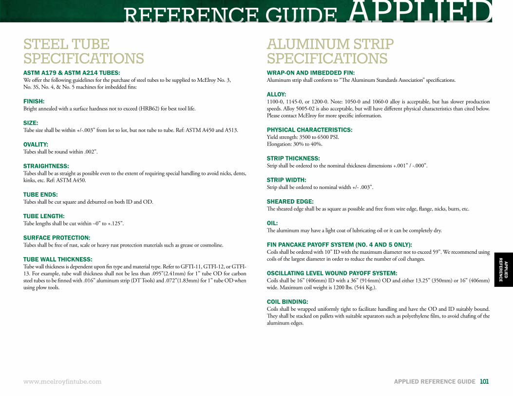
REFERENCE GUIDE APPLIED
www.mcelroyfintube.com
APPLIEDR
EFEREN
CE
APPLIED REFERENCE GUIDE 101
ASTM A179 & ASTM A214 TUBES:We offer the following guidelines for the purchase of steel tubes to be supplied to McElroy No. 3,No. 3S, No. 4, & No. 5 machines for imbedded fins:
FINISH:Bright annealed with a surface hardness not to exceed (HRB62) for best tool life.
SIZE:Tube size shall be within +/-.003” from lot to lot, but not tube to tube. Ref: ASTM A450 and A513.
OVALITY:Tubes shall be round within .002”.
STRAIGHTNESS:Tubes shall be as straight as possible even to the extent of requiring special handling to avoid nicks, dents, kinks, etc. Ref: ASTM A450.
TUBE ENDS:Tubes shall be cut square and deburred on both ID and OD.
TUBE LENGTH:Tube lengths shall be cut within –0” to +.125”.
SURFACE PROTECTION:Tubes shall be free of rust, scale or heavy rust protection materials such as grease or cosmoline.
TUBE WALL THICKNESS:Tube wall thickness is dependent upon fin type and material type. Refer to GFTI-11, GTFI-12, or GTFI-13. For example, tube wall thickness shall not be less than .095”(2.41mm) for 1” tube OD for carbon steel tubes to be finned with .016” aluminum strip (DT Tools) and .072”(1.83mm) for 1” tube OD when using plow tools.
WRAP-ON AND IMBEDDED FIN:Aluminum strip shall conform to “The Aluminum Standards Association” specifications.
ALLOY:1100-0, 1145-0, or 1200-0. Note: 1050-0 and 1060-0 alloy is acceptable, but has slower production speeds. Alloy 5005-02 is also acceptable, but will have different physical characteristics than cited below. Please contact McElroy for more specific information.
PHYSICAL CHARACTERISTICS:Yield strength: 3500 to 6500 PSI.Elongation: 30% to 40%.
STRIP THICKNESS:Strip shall be ordered to the nominal thickness dimensions +.001” / -.000”.
STRIP WIDTH:Strip shall be ordered to nominal width +/- .003”.
SHEARED EDGE:The sheared edge shall be as square as possible and free from wire edge, flange, nicks, burrs, etc.
OIL:The aluminum may have a light coat of lubricating oil or it can be completely dry.
FIN PANCAKE PAYOFF SYSTEM (NO. 4 AND 5 ONLY):Coils shall be ordered with 10” ID with the maximum diameter not to exceed 59”. We recommend using coils of the largest diameter in order to reduce the number of coil changes.
OSCILLATING LEVEL WOUND PAYOFF SYSTEM:Coils shall be 16” (406mm) ID with a 36” (914mm) OD and either 13.25” (350mm) or 16” (406mm) wide. Maximum coil weight is 1200 lbs. (544 Kg.).
COIL BINDING:Coils shall be wrapped uniformly tight to facilitate handling and have the OD and ID suitably bound. They shall be stacked on pallets with suitable separators such as polyethylene film, to avoid chafing of the aluminum edges.
STEEL TUBESPECIFICATIONS
ALUMINUM STRIPSPECIFICATIONS
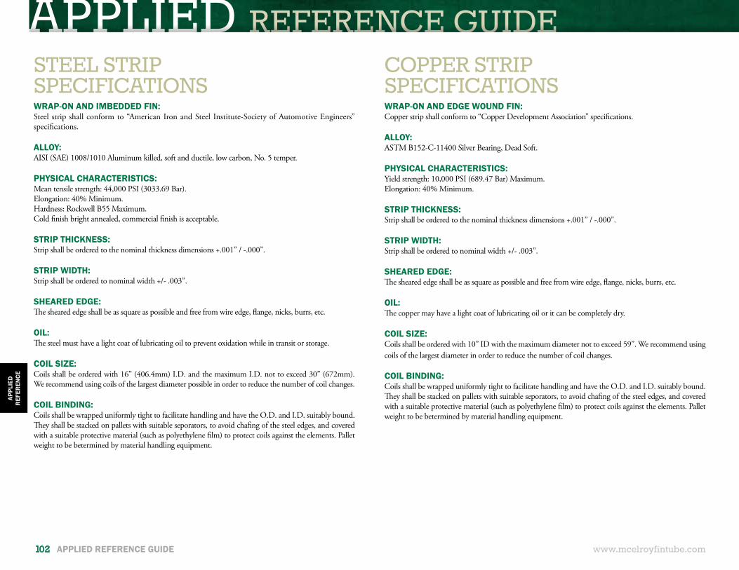
APPLIED REFERENCE GUIDE
www.mcelroyfintube.com
APPL
IED
REF
EREN
CE
102 APPLIED REFERENCE GUIDE
WRAP-ON AND IMBEDDED FIN:Steel strip shall conform to “American Iron and Steel Institute-Society of Automotive Engineers” specifications.
ALLOY:AISI (SAE) 1008/1010 Aluminum killed, soft and ductile, low carbon, No. 5 temper.
PHYSICAL CHARACTERISTICS:Mean tensile strength: 44,000 PSI (3033.69 Bar).Elongation: 40% Minimum.Hardness: Rockwell B55 Maximum.Cold finish bright annealed, commercial finish is acceptable.
STRIP THICKNESS:Strip shall be ordered to the nominal thickness dimensions +.001” / -.000”.
STRIP WIDTH:Strip shall be ordered to nominal width +/- .003”.
SHEARED EDGE:The sheared edge shall be as square as possible and free from wire edge, flange, nicks, burrs, etc.
OIL:The steel must have a light coat of lubricating oil to prevent oxidation while in transit or storage.
COIL SIZE:Coils shall be ordered with 16” (406.4mm) I.D. and the maximum I.D. not to exceed 30” (672mm). We recommend using coils of the largest diameter possible in order to reduce the number of coil changes.
COIL BINDING: Coils shall be wrapped uniformly tight to facilitate handling and have the O.D. and I.D. suitably bound. They shall be stacked on pallets with suitable seporators, to avoid chafing of the steel edges, and covered with a suitable protective material (such as polyethylene film) to protect coils against the elements. Pallet weight to be betermined by material handling equipment.
WRAP-ON AND EDGE WOUND FIN:Copper strip shall conform to “Copper Development Association” specifications.
ALLOY:ASTM B152-C-11400 Silver Bearing, Dead Soft.
PHYSICAL CHARACTERISTICS:Yield strength: 10,000 PSI (689.47 Bar) Maximum.Elongation: 40% Minimum.
STRIP THICKNESS:Strip shall be ordered to the nominal thickness dimensions +.001” / -.000”.
STRIP WIDTH:Strip shall be ordered to nominal width +/- .003”.
SHEARED EDGE:The sheared edge shall be as square as possible and free from wire edge, flange, nicks, burrs, etc.
OIL:The copper may have a light coat of lubricating oil or it can be completely dry.
COIL SIZE:Coils shall be ordered with 10” ID with the maximum diameter not to exceed 59”. We recommend using coils of the largest diameter in order to reduce the number of coil changes.
COIL BINDING: Coils shall be wrapped uniformly tight to facilitate handling and have the O.D. and I.D. suitably bound. They shall be stacked on pallets with suitable seporators, to avoid chafing of the steel edges, and covered with a suitable protective material (such as polyethylene film) to protect coils against the elements. Pallet weight to be betermined by material handling equipment.
STEEL STRIPSPECIFICATIONS
COPPER STRIPSPECIFICATIONS
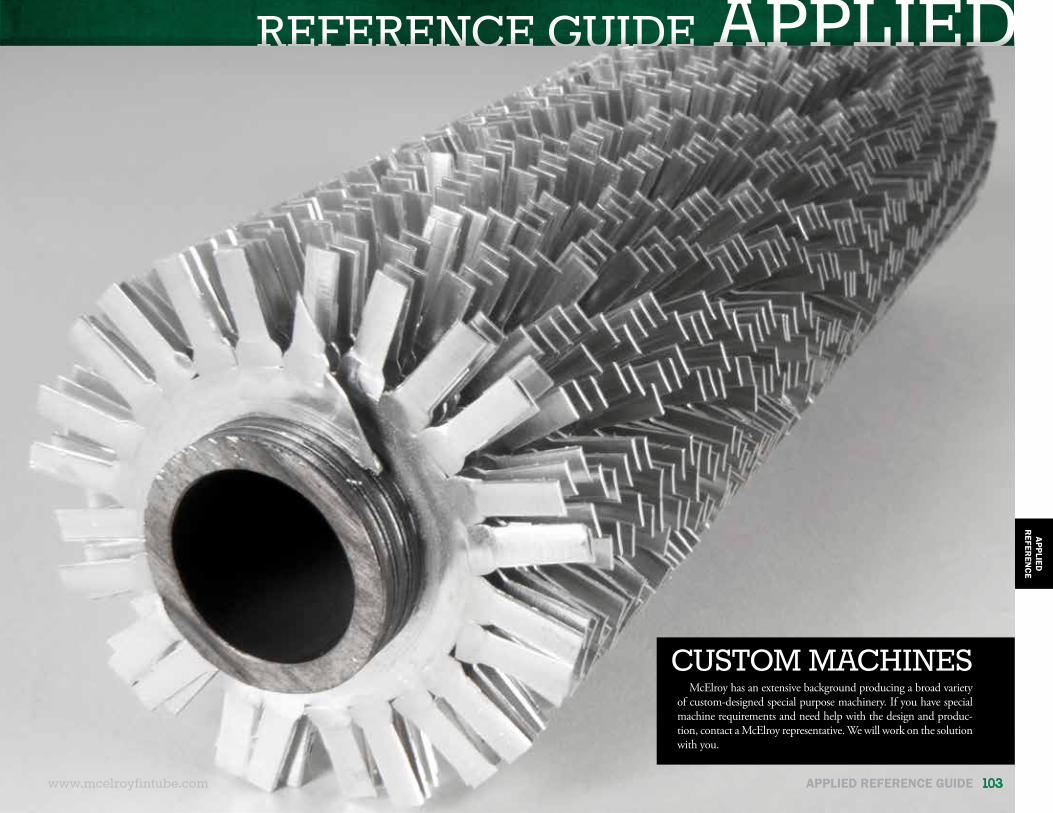
REFERENCE GUIDE APPLIEDAPPLIED
REFER
ENCE
McElroy has an extensive background producing a broad variety of custom-designed special purpose machinery. If you have special machine requirements and need help with the design and produc-tion, contact a McElroy representative. We will work on the solution with you.
CUSTOM MACHINES
www.mcelroyfintube.com APPLIED REFERENCE GUIDE 103
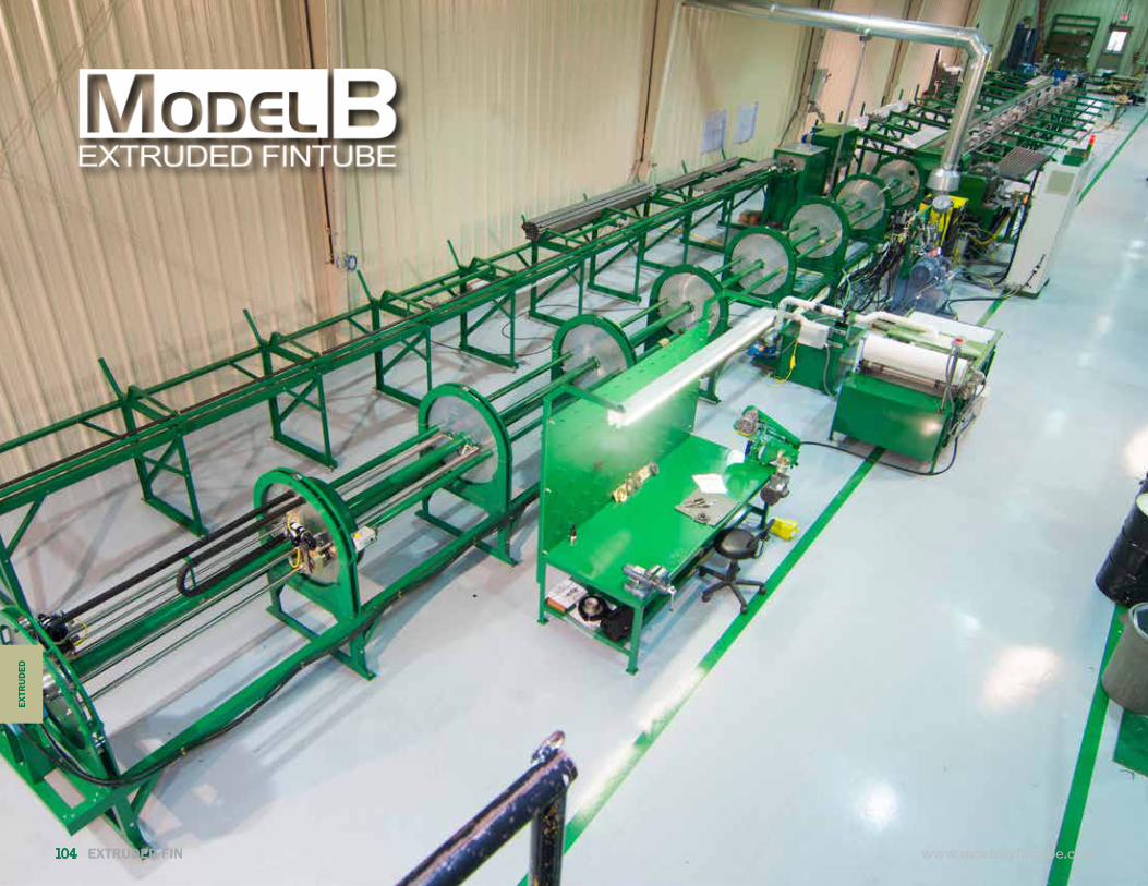
EXTRUDED FINAPPLIED REFERENCE GUIDEEX
TRU
DED
www.mcelroyfintube.com104 EXTRUDED FIN
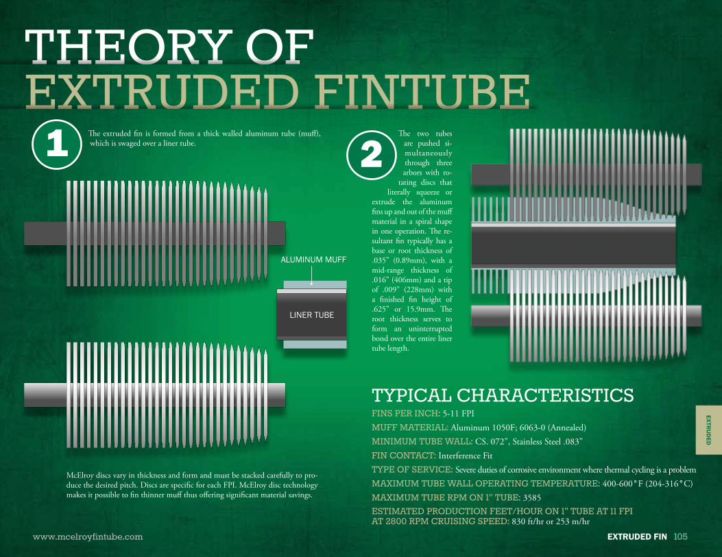
EXTRUDED FINAPPLIED REFERENCE GUIDEAPPLIED REFERENCE GUIDETHEORY OFEXTRUDED FINTUBE
www.mcelroyfintube.com
EXTRU
DED
EXTRUDED FIN 105
The extruded fin is formed from a thick walled aluminum tube (muff), which is swaged over a liner tube.
The two tubes are pushed si-multaneously through three arbors with ro-
tating discs that literally squeeze or
extrude the aluminum fins up and out of the muff material in a spiral shape in one operation. The re-sultant fin typically has a base or root thickness of .035” (0.89mm), with a mid-range thickness of .016” (406mm) and a tip of .009” (228mm) with a finished fin height of .625” or 15.9mm. The root thickness serves to form an uninterrupted bond over the entire liner tube length.
McElroy discs vary in thickness and form and must be stacked carefully to pro-duce the desired pitch. Discs are specific for each FPI. McElroy disc technology makes it possible to fin thinner muff thus offering significant material savings.
21
ALUMINUM MUFF
LINER TUBE
FINS PER INCH: 5-11 FPIMUFF MATERIAL: Aluminum 1050F; 6063-0 (Annealed)MINIMUM TUBE WALL: CS. 072”, Stainless Steel .083”FIN CONTACT: Interference FitTYPE OF SERVICE: Severe duties of corrosive environment where thermal cycling is a problemMAXIMUM TUBE WALL OPERATING TEMPERATURE: 400-600°F (204-316°C)MAXIMUM TUBE RPM ON 1” TUBE: 3585ESTIMATED PRODUCTION FEET/HOUR ON 1” TUBE AT 11 FPIAT 2800 RPM CRUISING SPEED: 830 ft/hr or 253 m/hr
TYPICAL CHARACTERISTICS

EXTRUDED FIN
www.mcelroyfintube.com
EXTR
UD
ED
106 EXTRUDED FIN
MODEL B MACHINE CAPABILITIES
MODEL B MACHINE SPECIFICATIONS
MODEL B MACHINE BENEFITS
Tube Size: 1” – 1.5” (25mm – 38.1mm)Fin Heights: 0.5” – 0.625” (12.7mm – 15.8mm)Fins Per Inch (FPI): 5 – 11Fin Material: AluminumMuff maximum tube RPM on 1” tube: 3585
LENGTH: 50 foot Machines: 33.83 meters (111 feet)60 foot Machines: 39.93 meters (131 feet)
WIDTH: 9.4 meters (30 feet)
TYPICAL TUBE LENGTH: 15.2 meters (50 feet) Extensions available for up to 18.3 meters (60 foot tube). Other rack lengths available.
POWER REQUIREMENT:
• SUPPLY TYPE: 3-phase, 242 kVA solidly grounded (earthed-type) and protected by 350 Amp Class-J, time-delay fuses with a disconnect conforming to local regulations.
• VOLTAGE: 400V
• FREQUENCY: 50Hz (Other voltages and frequencies evaluated upon request.)
HORSEPOWER: 150 HP AC Motor
MANPOWER: One full-time operator, one disc stacker, and two helpers.
COMPLETE SOLUTIONWe offer the flexibility to customize fintube production cells to suit customer needs. Through
the resources of our sales and engineering departments, we can help you choose the best options for your specific applications. We offer precision components, top quality controls, and a knowledgeable staff dedicated to supporting your needs. For maximum production and efficiency, the following features are included with the standard Model B Extruded fintube machine:
• Liner Tube Rack • Liner Tube Cleaning and Polishing Station• Storage Rack for Fin Material and Liner Tubes• Input Rack• Finning head• Inline high pressure cleaner for finned tubes• Quick Change Finned Tube Rack• Highly efficient cooling system • Hydraulically operated end strippers
HIGH SPEED PRODUCTIONMcElroy machines offer a maximum production of tubes per man hour, this is due to our high
speed operation, a tube cruising speed of 2,800 RPM and a productivity minded design.
QUALITYMcElroy extruded discs are manufactured from high quality materials under exacting
conditions to offer you the greatest number of cycles possible.
TECHNOLOGYThrough the technology that McElroy fintube machines offer there is excellent tube to finned
material contact surface, thus providing maximum efficiency and long tube life. Our disc technology makes it possible to fin thinner material thus offering significant material savings.
VERSATILITYMcElroy heavy-duty adjustable arbors can be set up for different fintube combinations and
depths thus accommodating for different fin material thicknesses. The same extruded discs can be used to produce multiple fin heights. For example, the same disc can produce 0.5” (12.70mm) and 0.625” (15.88mm) high fin.
RELIABILTIY
Our highly efficient cooling system equipped with a high flow centrifugal pump and filter system keeps plenty of clean lubricant flowing for the greatest disc life and reliability.
EASY MAINTENANCE Accessibility to the finning head makes maintenance procedures simple and fast to execute.

EXTRUDED FIN
www.mcelroyfintube.com
EXTRU
DED
EXTRUDED FIN 107
MODEL B EXTRUDED MACHINEThe diagram below shows the overall components of the Extruded Model B machine. The equipment offers complete tube
processing and handling.
BASKET (CUSTOMER SUPPLIED)
HYDRAULIC POWER UNIT
HANDLER
STRIPPER (MOVABLE)TANK WITH 15,000 WATT HEATER
COOLANT RETURN TANK
TRAVELING MEDIA FILTER AND330 GALLON COOLANT TANK
LINER TUBE GRAVITY FEED RACKLINER TUBE BUNDLE CRADLE
DOUBLE BARREL
DISC POLISHING STATIONDISCSTACKER
MUFF TUBE BUNDLE
STRIPPER (FIXED)
FIN HEAD
FINNED TUBE WASHING UNIT
OPERATOR STATION
ELECTRICAL CONTROL CABINET
3 COMPARTMENTTUBE CLEANING STATION
ALUMINUM MUFF (UPPER)
GRAVITY FEED RACKCRADLE
GRAVITY FEED RACK
CLEAN LINERS (LOWER)
FINNED TUBE RACKQUICK CHANGE
INPUT RACK
TUBE HANDLER
HYDRAULIC FIN HYDRAULIC FIN
FINNED TUBESTORAGE
FINNED TUBE STORAGE
TUBE
PART NO. DESCRIPTION LENGTH(ft/m)
WIDTH(ft/m)
E010007 50’ Maximum Tube Length 119’-36.27” (37.19m) 19’-5.79” (5.94m)
E010008 60’ Maximum Tube Length 139’-24.36” (42.99m) 19’-5.79” (5.94m)
BASKET (CUSTOMER SUPPLIED)
HYDRAULIC POWER UNIT
HANDLER
STRIPPER (MOVABLE)
ISOLATION TRANSFORMER
TANK WITH 15,000 WATT HEATER
COOLANT RETURN
TRAVELING MEDIA FILTER AND330 GALLON COOLANT TANK
LINER TUBE GRAVITY FEED RACKLINER TUBE BUNDLE CRADLE
DOUBLE BARREL
DISC POLISHING STATION
TANK
MUFF TUBE BUNDLE
STRIPPER (FIXED)
FIN HEAD
FINNED TUBE WASHING UNIT
OPERATOR STATION
ELECTRICAL CONTROL CABINET
3 COMPARTMENTTUBE CLEANING STATIONALUMINUM MUFF (UPPER)
GRAVITY FEED RACKCRADLE
GRAVITY FEED RACKCLEAN LINERS (LOWER)
FINNED TUBE RACKQUICK CHANGE
INPUT RACK
TUBE HANDLER
HYDRAULIC FIN HYDRAULIC FIN
FINNED TUBESTORAGEFINNED TUBE STORAGE
TUBE
SECTION A-A
HEADCLEANER
SECTION B-B
TO TUBETO FINNING
FLOOR LINE
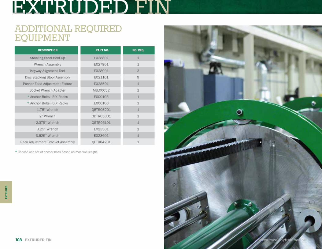
EXTRUDED FIN
www.mcelroyfintube.com
EXTR
UD
ED
108 EXTRUDED FIN
DESCRIPTION PART NO. NO. REQ.
Stacking Stool Hold Up E028801 1
Wrench Assembly E027901 1
Keyway Alignment Tool E028001 3
Disc Stacking Stool Assembly E021101 9
Pusher Feed Adjustment Fixture E028501 1
Socket Wrench Adapter MJL00052 1
* Anchor Bolts - 50’ Racks E000105 1
* Anchor Bolts - 60’ Racks E000106 1
1.75” Wrench QBTR05201 1
2” Wrench QBTR05001 1
2.375” Wrench QBTR05101 1
3.25” Wrench E023501 1
3.625” Wrench E023601 1
Rack Adjustment Bracket Assembly QFTR04201 1
ADDITIONAL REQUIRED EQUIPMENT
* Choose one set of anchor bolts based on machine length.

EXTRUDED FINEND-USERRESPONSIBILITIES
www.mcelroyfintube.com
EXTRU
DED
EXTRUDED FIN 109
PRIOR TO INSTALLATION HOW WE SHIP• The customer is responsible for proper floor preparations, providing for electrical, air supply and other utilities as outlined below and the actual connection of the equipment to incoming plant voltage.
• Power supply should be constant and not inconsistent.
• The machine draws 150 HP at 100% RPM. Adequate horsepower is designed into this equipment to provide for the running of harder materials and larger ODs. It is required that the end user provide adequate electrical service. Customer to provide con- nection from incoming source to transformer and from transformer to controller. The proper method of electrical connection is described in the manual and must be completed by a licensed electrician.
• Air requirement: End user will need to arrange for a compressor to provide 30 CFM at 100 PSI. A dryer on the compressor is required. End user needs to run a .75” (19.05mm) ID line to the machine, fitted with a shop air fitting or quick disconnect.
• Water for Wash Tank: .625” (16mm) line with no less than 30 PSI pressure.
• Floor Drain: 7 gallons per minute.
• City water, gas line and drain for finned tube cleaning line.
• Gas pressure required is 11” WC (water column inches). Install in accordance with local building and safety codes.
• Vent pipe from steam cleaning unit.
• The machine needs to be laid out off of a centerline (chalk line). Make the layout and drill holes off this centerline for the ma- chine and racks. It is recommended that a drill guide be used to ensure that the holes are straight. It is also necessary to level and align the machine by using a bubble level and laser. Anchor bolts, shields, anchor shield drivers, masonry drills as well as the laser are shipped with the machine. See specific dimensions based on your setting plan which will be provided at the time of order.
• For setup and run in of the machine, the end user will need to provide liner tubes and muff material of a recognized alloy, as specified. Test material is to be provided for final testing at McElroy’s facility prior to shipping.
• It is recommended that a team consisting of operations, maintenance, engineering and supervisory management be selected for training. McElroy will be involved in setting up the schedule for training and commissioning prior to dispatch of our technical personnel for installation of the equipment.
INTERNATIONAL SHIPMENT:The 60 feet and 50 feet machine and components are skidded for ease of offloading. Machine ships in four (4) high cube, 40 foot containers. Typical weight, of each container is as follows:
Container 1—14,000 lbs (6,350 kg)Container 2—14,000 lbs (6,350 kg)Container 3—13,000 lbs (5,897 kg)Container 4—24,000 lbs (10,886 kg)
Final packing list details each component in each container and is pro-vided at the time of dispatch so you can be prepared to receive each container. Lifting points are also indicated on each skid to facilitate offloading.
DOMESTIC SHIPMENT:Usually made on 45 foot floats and may require up to four trucks. It is recommended that the truck be tarped or enclosed to protect the equipment during transit.
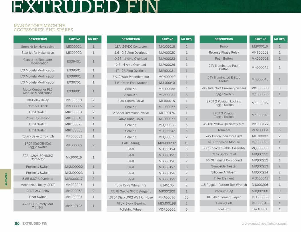
EXTRUDED FINDESCRIPTION PART NO. NO. REQ.
Knob MJP00015 1
Reverse Phase Relay MKB00003 1
Push Button MKC00001 1
24V Illuminated PushButton MKC00042 1
24V Illuminated E-StopSwitch MKC00043 1
24V Inductive Proximity Sensor MKD00030 3
Toggle Switch MKE00006 1
SPDT 2 Position LockingToggle Switch MKE00072 1
SPDT 3 Position Toggle Switch MKE00073 2
42X30 Yellow QD Safety Mat MKH00122 1
Terminal MLM00051 5
24V Green Indicator Light MLT00002 2
I/O Expansion Module MQE00095 1
30ft Encoder Cable Assembly MQG00055 1
Cans Spray Paint MJQ00351 3
55 Gl Finning Compound MJQ00212 1
Sumpside Treater MJQ00213 2
Silicone Antifoam MJQ00214 2
Filter Element MED00042 1
1.5 Regular Pattern Box Wrench MJQ00206 1
Vacuum Bag MJQ00208 3
Rl. Filter Element Paper MED00038 2
Timing Belt MDE00043 1
Tool Box SW16001 1
www.mcelroyfintube.com110 EXTRUDED FIN
EXTR
UD
ED
DESCRIPTION PART NO. NO. REQ.
Stem kit for Hoke valve MEI00021 1
Seat kit for Hoke valve MEI00022 1
Converter/Repeater Modification E039401 1
I/O Module Modification E039501 1
I/O Module Modification E039601 1
I/O Module Modification E039701 1
Motor Controller PLCModule Modification E039901 1
Off-Delay Relay MKB00051 2
Contact Block MKC00002 2
Limit Switch MKD00004 2
Proximity Sensor MKD00018 1
Limit Switch MKD00026 1
Limit Switch MKD00035 1
Rotary Selector Switch MKE00031 1
SPDT (On)-Off-(On) Toggle Switch MKE00082 2
32A, 120V, 50/60HZContactor MKJ00015 1
Proximity Switch MKM00022 1
Proximity Switch MKM00023 1
5.85-6.67 A Overload MLV000017 3
Mechanical Relay, 2PDT MKB00007 1
2PDT 24V Relay MKB00058 2
Float Switch MKD00037 1
42” X 30” Safety MatTrim Kit MKH00123 1
MANDATORY MACHINE ACCESSORIES AND SPARES
DESCRIPTION PART NO. NO. REQ.
18A, 24VDC Contactor MKJ00019 2
1.6 - 2.5 Amp Overload MLV00020 1
0.63 - 1 Amp Overload MLV00023 1
2.5 - 4 Amp Overload MLV00026 1
17 - 25 Amp Overload MLV00031 1
5K, 2 Watt Potentiometer MQH00010 1
1.5” Open End Wrench MJL00040 1
Seal Kit MEP00055 2
Spool Kit MGF00034 3
Flow Control Valve MEJ00015 1
Seal Kit MEP00057 2
2 Spool Directional Valve MEF00174 1
Valve Hand Lever MEF00077 1
Seal Kit MEQ00038 5
Seal Kit MEQ00047 5
Seal Kit MEQ00039 2
Ball Bearing MDM00232 15
Seal MDL00124 3
Seal MDL00125 3
Seal MDL00126 2
Seal MDL00127 3
Seal MDL00128 2
Seal MDL00129 2
Tube Drive Wheel Tire E145105 2
55 Gl Oakite STC Detergent MJQ00209 1
.375” Dia X .062 Wall Air Hose MHA00030 60
Pillow Block Bearing MDM00198 2
Polishing Wheel MDR00052 6
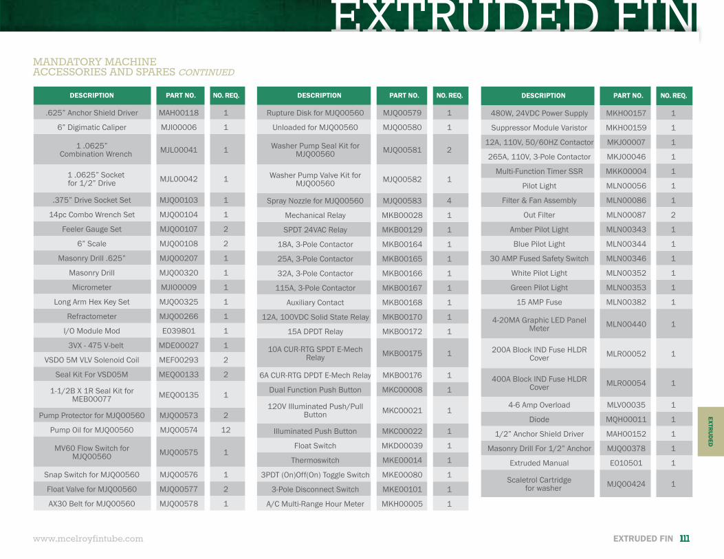
EXTRUDED FINDESCRIPTION PART NO. NO. REQ.
Rupture Disk for MJQ00560 MJQ00579 1
Unloaded for MJQ00560 MJQ00580 1
Washer Pump Seal Kit for MJQ00560 MJQ00581 2
Washer Pump Valve Kit for MJQ00560 MJQ00582 1
Spray Nozzle for MJQ00560 MJQ00583 4
Mechanical Relay MKB00028 1
SPDT 24VAC Relay MKB00129 1
18A, 3-Pole Contactor MKB00164 1
25A, 3-Pole Contactor MKB00165 1
32A, 3-Pole Contactor MKB00166 1
115A, 3-Pole Contactor MKB00167 1
Auxiliary Contact MKB00168 1
12A, 100VDC Solid State Relay MKB00170 1
15A DPDT Relay MKB00172 1
10A CUR-RTG SPDT E-Mech Relay MKB00175 1
6A CUR-RTG DPDT E-Mech Relay MKB00176 1
Dual Function Push Button MKC00008 1
120V Illuminated Push/Pull Button MKC00021 1
Illuminated Push Button MKC00022 1
Float Switch MKD00039 1
Thermoswitch MKE00014 1
3PDT (On)Off(On) Toggle Switch MKE00080 1
3-Pole Disconnect Switch MKE00101 1
A/C Multi-Range Hour Meter MKH00005 1
www.mcelroyfintube.com
EXTRU
DED
EXTRUDED FIN 111
MANDATORY MACHINE ACCESSORIES AND SPARES CONTINUED
DESCRIPTION PART NO. NO. REQ.
.625” Anchor Shield Driver MAH00118 1
6” Digimatic Caliper MJI00006 1
1 .0625” Combination Wrench MJL00041 1
1 .0625” Socket for 1/2” Drive MJL00042 1
.375” Drive Socket Set MJQ00103 1
14pc Combo Wrench Set MJQ00104 1
Feeler Gauge Set MJQ00107 2
6” Scale MJQ00108 2
Masonry Drill .625” MJQ00207 1
Masonry Drill MJQ00320 1
Micrometer MJI00009 1
Long Arm Hex Key Set MJQ00325 1
Refractometer MJQ00266 1
I/O Module Mod E039801 1
3VX - 475 V-belt MDE00027 1
VSDO 5M VLV Solenoid Coil MEF00293 2
Seal Kit For VSD05M MEQ00133 2
1-1/2B X 1R Seal Kit for MEB00077 MEQ00135 1
Pump Protector for MJQ00560 MJQ00573 2
Pump Oil for MJQ00560 MJQ00574 12
MV60 Flow Switch for MJQ00560 MJQ00575 1
Snap Switch for MJQ00560 MJQ00576 1
Float Valve for MJQ00560 MJQ00577 2
AX30 Belt for MJQ00560 MJQ00578 1
DESCRIPTION PART NO. NO. REQ.
480W, 24VDC Power Supply MKH00157 1
Suppressor Module Varistor MKH00159 1
12A, 110V, 50/60HZ Contactor MKJ00007 1
265A, 110V, 3-Pole Contactor MKJ00046 1
Multi-Function Timer SSR MKK00004 1
Pilot Light MLN00056 1
Filter & Fan Assembly MLN00086 1
Out Filter MLN00087 2
Amber Pilot Light MLN00343 1
Blue Pilot Light MLN00344 1
30 AMP Fused Safety Switch MLN00346 1
White Pilot Light MLN00352 1
Green Pilot Light MLN00353 1
15 AMP Fuse MLN00382 1
4-20MA Graphic LED Panel Meter MLN00440 1
200A Block IND Fuse HLDR Cover MLR00052 1
400A Block IND Fuse HLDR Cover MLR00054 1
4-6 Amp Overload MLV00035 1
Diode MQH00011 1
1/2” Anchor Shield Driver MAH00152 1
Masonry Drill For 1/2” Anchor MJQ00378 1
Extruded Manual E010501 1
Scaletrol Cartridgefor washer MJQ00424 1
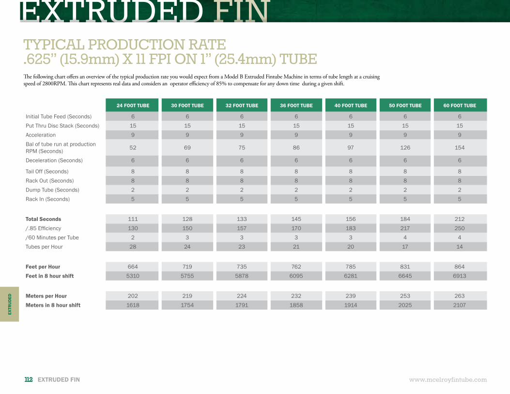
EXTRUDED FIN
www.mcelroyfintube.com112 EXTRUDED FIN
24 FOOT TUBE 30 FOOT TUBE 32 FOOT TUBE 36 FOOT TUBE 40 FOOT TUBE 50 FOOT TUBE 60 FOOT TUBE
Initial Tube Feed (Seconds) 6 6 6 6 6 6 6Put Thru Disc Stack (Seconds) 15 15 15 15 15 15 15Acceleration 9 9 9 9 9 9 9Bal of tube run at production RPM (Seconds) 52 69 75 86 97 126 154
Deceleration (Seconds) 6 6 6 6 6 6 6
Tail Off (Seconds) 8 8 8 8 8 8 8Rack Out (Seconds) 8 8 8 8 8 8 8Dump Tube (Seconds) 2 2 2 2 2 2 2Rack In (Seconds) 5 5 5 5 5 5 5
Total Seconds 111 128 133 145 156 184 212/.85 Efficiency 130 150 157 170 183 217 250/60 Minutes per Tube 2 3 3 3 3 4 4Tubes per Hour 28 24 23 21 20 17 14
Feet per Hour 664 719 735 762 785 831 864Feet in 8 hour shift 5310 5755 5878 6095 6281 6645 6913
Meters per Hour 202 219 224 232 239 253 263Meters in 8 hour shift 1618 1754 1791 1858 1914 2025 2107
TYPICAL PRODUCTION RATE.625” (15.9mm) X 11 FPI ON 1” (25.4mm) TUBEThe following chart offers an overview of the typical production rate you would expect from a Model B Extruded Fintube Machine in terms of tube length at a cruising speed of 2800RPM. This chart represents real data and considers an operator efficiency of 85% to compensate for any down time during a given shift.
EXTR
UD
ED
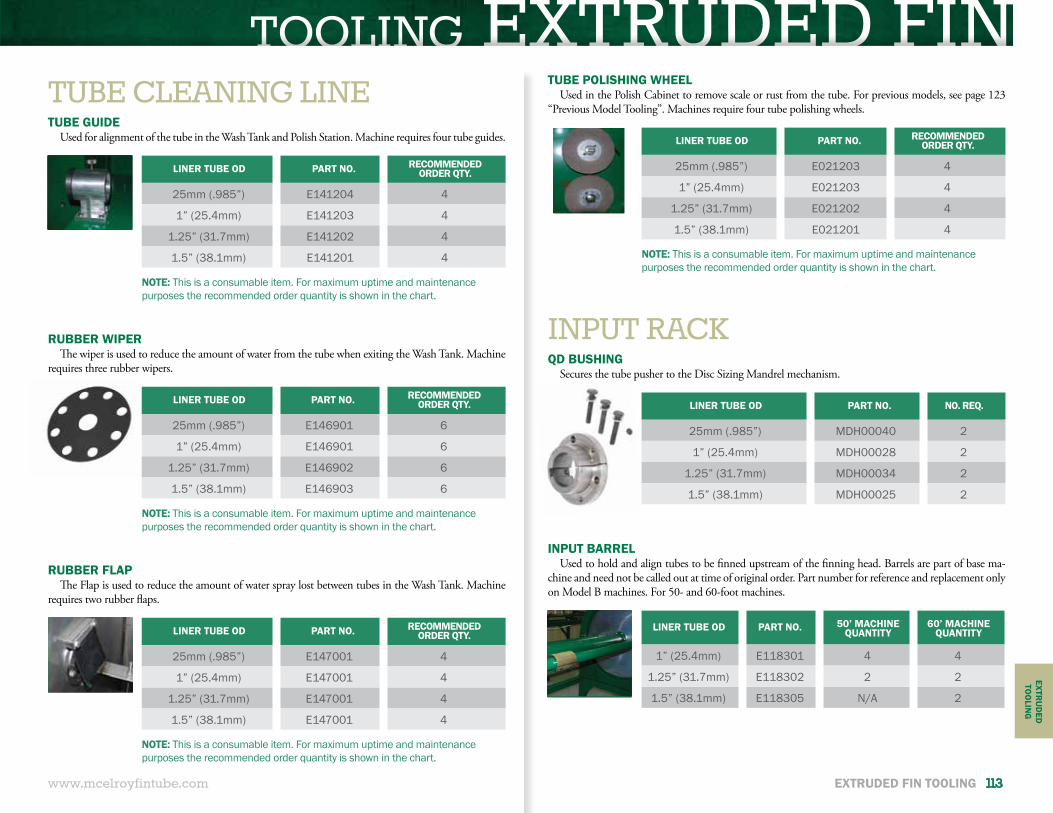
TOOLING EXTRUDED FIN
www.mcelroyfintube.com
EXTRU
DED
TOO
LING
EXTRUDED FIN TOOLING 113
TUBE CLEANING LINE
INPUT RACK
TUBE GUIDEUsed for alignment of the tube in the Wash Tank and Polish Station. Machine requires four tube guides.
TUBE POLISHING WHEELUsed in the Polish Cabinet to remove scale or rust from the tube. For previous models, see page 123
“Previous Model Tooling”. Machines require four tube polishing wheels.
QD BUSHINGSecures the tube pusher to the Disc Sizing Mandrel mechanism.
INPUT BARRELUsed to hold and align tubes to be finned upstream of the finning head. Barrels are part of base ma-
chine and need not be called out at time of original order. Part number for reference and replacement only on Model B machines. For 50- and 60-foot machines.
RUBBER WIPERThe wiper is used to reduce the amount of water from the tube when exiting the Wash Tank. Machine
requires three rubber wipers.
RUBBER FLAPThe Flap is used to reduce the amount of water spray lost between tubes in the Wash Tank. Machine
requires two rubber flaps.
LINER TUBE OD PART NO. RECOMMENDED ORDER QTY.
25mm (.985”) E141204 4
1” (25.4mm) E141203 4
1.25” (31.7mm) E141202 4
1.5” (38.1mm) E141201 4
LINER TUBE OD PART NO. RECOMMENDED ORDER QTY.
25mm (.985”) E021203 4
1” (25.4mm) E021203 4
1.25” (31.7mm) E021202 4
1.5” (38.1mm) E021201 4
LINER TUBE OD PART NO. NO. REQ.
25mm (.985”) MDH00040 2
1” (25.4mm) MDH00028 2
1.25” (31.7mm) MDH00034 2
1.5” (38.1mm) MDH00025 2
LINER TUBE OD PART NO. 50’ MACHINEQUANTITY
60’ MACHINEQUANTITY
1” (25.4mm) E118301 4 4
1.25” (31.7mm) E118302 2 2
1.5” (38.1mm) E118305 N/A 2
LINER TUBE OD PART NO. RECOMMENDED ORDER QTY.
25mm (.985”) E146901 6
1” (25.4mm) E146901 6
1.25” (31.7mm) E146902 6
1.5” (38.1mm) E146903 6
LINER TUBE OD PART NO. RECOMMENDED ORDER QTY.
25mm (.985”) E147001 4
1” (25.4mm) E147001 4
1.25” (31.7mm) E147001 4
1.5” (38.1mm) E147001 4
NOTE: This is a consumable item. For maximum uptime and maintenance purposes the recommended order quantity is shown in the chart.
NOTE: This is a consumable item. For maximum uptime and maintenance purposes the recommended order quantity is shown in the chart.
NOTE: This is a consumable item. For maximum uptime and maintenance purposes the recommended order quantity is shown in the chart.
NOTE: This is a consumable item. For maximum uptime and maintenance purposes the recommended order quantity is shown in the chart.
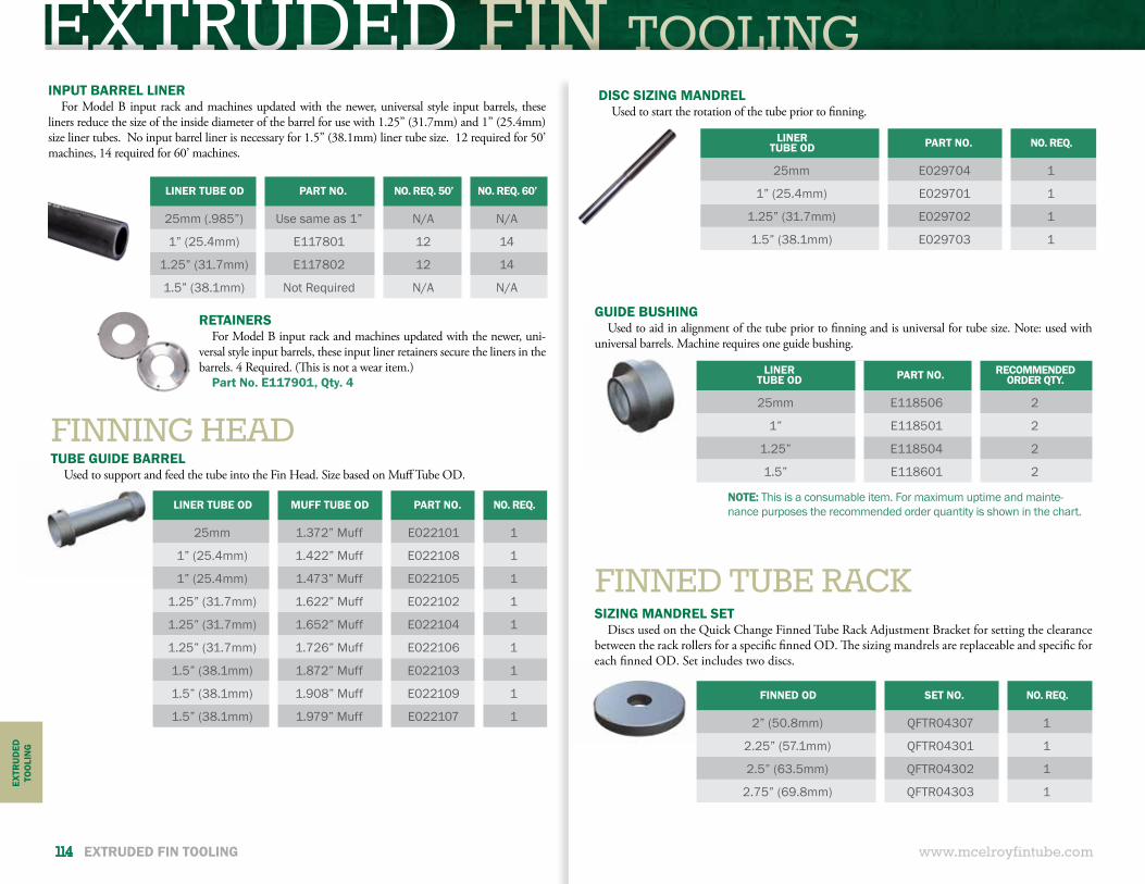
EXTRUDED FIN TOOLINGINPUT BARREL LINER
For Model B input rack and machines updated with the newer, universal style input barrels, these liners reduce the size of the inside diameter of the barrel for use with 1.25” (31.7mm) and 1” (25.4mm) size liner tubes. No input barrel liner is necessary for 1.5” (38.1mm) liner tube size. 12 required for 50’ machines, 14 required for 60’ machines.
RETAINERSFor Model B input rack and machines updated with the newer, uni-
versal style input barrels, these input liner retainers secure the liners in the barrels. 4 Required. (This is not a wear item.)
Part No. E117901, Qty. 4
www.mcelroyfintube.com
EXTR
UD
EDTO
OLI
NG
114 EXTRUDED FIN TOOLING
FINNING HEAD
FINNED TUBE RACK
TUBE GUIDE BARRELUsed to support and feed the tube into the Fin Head. Size based on Muff Tube OD.
SIZING MANDREL SETDiscs used on the Quick Change Finned Tube Rack Adjustment Bracket for setting the clearance
between the rack rollers for a specific finned OD. The sizing mandrels are replaceable and specific for each finned OD. Set includes two discs.
DISC SIZING MANDRELUsed to start the rotation of the tube prior to finning.
GUIDE BUSHINGUsed to aid in alignment of the tube prior to finning and is universal for tube size. Note: used with
universal barrels. Machine requires one guide bushing.
LINER TUBE OD MUFF TUBE OD PART NO. NO. REQ.
25mm 1.372” Muff E022101 1
1” (25.4mm) 1.422” Muff E022108 1
1” (25.4mm) 1.473” Muff E022105 1
1.25” (31.7mm) 1.622” Muff E022102 1
1.25” (31.7mm) 1.652” Muff E022104 1
1.25” (31.7mm) 1.726” Muff E022106 1
1.5” (38.1mm) 1.872” Muff E022103 1
1.5” (38.1mm) 1.908” Muff E022109 1
1.5” (38.1mm) 1.979” Muff E022107 1
FINNED OD SET NO. NO. REQ.
2” (50.8mm) QFTR04307 1
2.25” (57.1mm) QFTR04301 1
2.5” (63.5mm) QFTR04302 1
2.75” (69.8mm) QFTR04303 1
LINERTUBE OD PART NO. RECOMMENDED
ORDER QTY.
25mm E118506 2
1” E118501 2
1.25” E118504 2
1.5” E118601 2
LINERTUBE OD PART NO. NO. REQ.
25mm E029704 1
1” (25.4mm) E029701 1
1.25” (31.7mm) E029702 1
1.5” (38.1mm) E029703 1
NOTE: This is a consumable item. For maximum uptime and mainte-nance purposes the recommended order quantity is shown in the chart.
LINER TUBE OD PART NO. NO. REQ. 50’ NO. REQ. 60’
25mm (.985”) Use same as 1” N/A N/A
1” (25.4mm) E117801 12 14
1.25” (31.7mm) E117802 12 14
1.5” (38.1mm) Not Required N/A N/A
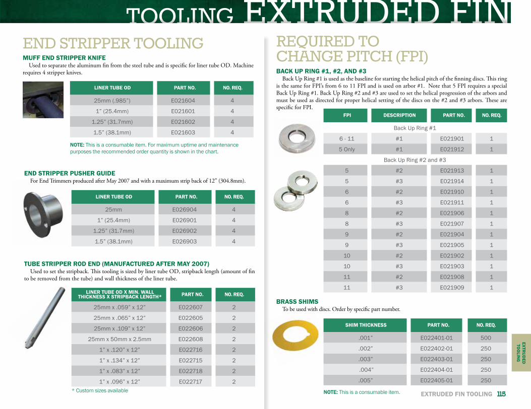
TOOLING EXTRUDED FINEXTR
UD
EDTO
OLIN
G
EXTRUDED FIN TOOLING 115
REQUIRED TOCHANGE PITCH (FPI)BACK UP RING #1, #2, AND #3
Back Up Ring #1 is used as the baseline for starting the helical pitch of the finning discs. This ring is the same for FPI’s from 6 to 11 FPI and is used on arbor #1. Note that 5 FPI requires a special Back Up Ring #1. Back Up Ring #2 and #3 are used to set the helical progression of the arbors and must be used as directed for proper helical setting of the discs on the #2 and #3 arbors. These are specific for FPI.
TUBE STRIPPER ROD END (MANUFACTURED AFTER MAY 2007)Used to set the stripback. This tooling is sized by liner tube OD, stripback length (amount of fin
to be removed from the tube) and wall thickness of the liner tube.
FPI DESCRIPTION PART NO. NO. REQ.
Back Up Ring #1
6 - 11 #1 E021901 1
5 Only #1 E021912 1
Back Up Ring #2 and #3
5 #2 E021913 1
5 #3 E021914 1
6 #2 E021910 1
6 #3 E021911 1
8 #2 E021906 1
8 #3 E021907 1
9 #2 E021904 1
9 #3 E021905 1
10 #2 E021902 1
10 #3 E021903 1
11 #2 E021908 1
11 #3 E021909 1LINER TUBE OD X MIN. WALL
THICKNESS X STRIPBACK LENGTH* PART NO. NO. REQ.
25mm x .059” x 12” E022607 2
25mm x .065” x 12” E022605 2
25mm x .109” x 12” E022606 2
25mm x 50mm x 2.5mm E022608 2
1” x .120” x 12” E022716 2
1” x .134” x 12” E022715 2
1” x .083” x 12” E022718 2
1” x .096” x 12” E022717 2* Custom sizes available
BRASS SHIMSTo be used with discs. Order by specific part number.
SHIM THICKNESS PART NO. NO. REQ.
.001” E022401-01 500
.002” E022402-01 250
.003” E022403-01 250
.004” E022404-01 250
.005” E022405-01 250
NOTE: This is a consumable item.
END STRIPPER TOOLINGMUFF END STRIPPER KNIFE
Used to separate the aluminum fin from the steel tube and is specific for liner tube OD. Machine requires 4 stripper knives.
END STRIPPER PUSHER GUIDEFor End Trimmers produced after May 2007 and with a maximum strip back of 12” (304.8mm).
LINER TUBE OD PART NO. NO. REQ.
25mm (.985”) E021604 4
1” (25.4mm) E021601 4
1.25” (31.7mm) E021602 4
1.5” (38.1mm) E021603 4
LINER TUBE OD PART NO. NO. REQ.
25mm E026904 4
1” (25.4mm) E026901 4
1.25” (31.7mm) E026902 4
1.5” (38.1mm) E026903 4
NOTE: This is a consumable item. For maximum uptime and maintenance purposes the recommended order quantity is shown in the chart.
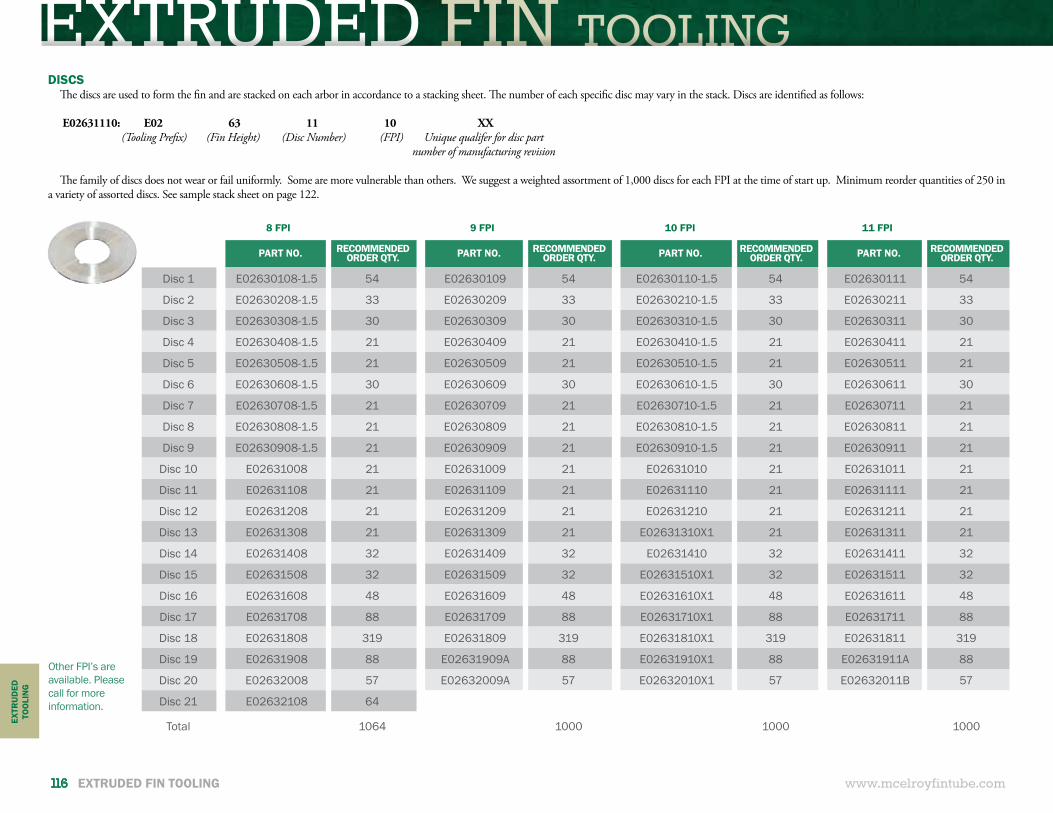
EXTRUDED FIN TOOLING
www.mcelroyfintube.com
EXTR
UD
EDTO
OLI
NG
116 EXTRUDED FIN TOOLING
DISCSThe discs are used to form the fin and are stacked on each arbor in accordance to a stacking sheet. The number of each specific disc may vary in the stack. Discs are identified as follows:
E02631110: E02 63 11 10 XX
The family of discs does not wear or fail uniformly. Some are more vulnerable than others. We suggest a weighted assortment of 1,000 discs for each FPI at the time of start up. Minimum reorder quantities of 250 in a variety of assorted discs. See sample stack sheet on page 122.
PART NO. RECOMMENDED ORDER QTY. PART NO. RECOMMENDED
ORDER QTY. PART NO. RECOMMENDED ORDER QTY. PART NO. RECOMMENDED
ORDER QTY.
Disc 1 E02630108-1.5 54 E02630109 54 E02630110-1.5 54 E02630111 54
Disc 2 E02630208-1.5 33 E02630209 33 E02630210-1.5 33 E02630211 33
Disc 3 E02630308-1.5 30 E02630309 30 E02630310-1.5 30 E02630311 30
Disc 4 E02630408-1.5 21 E02630409 21 E02630410-1.5 21 E02630411 21
Disc 5 E02630508-1.5 21 E02630509 21 E02630510-1.5 21 E02630511 21
Disc 6 E02630608-1.5 30 E02630609 30 E02630610-1.5 30 E02630611 30
Disc 7 E02630708-1.5 21 E02630709 21 E02630710-1.5 21 E02630711 21
Disc 8 E02630808-1.5 21 E02630809 21 E02630810-1.5 21 E02630811 21
Disc 9 E02630908-1.5 21 E02630909 21 E02630910-1.5 21 E02630911 21
Disc 10 E02631008 21 E02631009 21 E02631010 21 E02631011 21
Disc 11 E02631108 21 E02631109 21 E02631110 21 E02631111 21
Disc 12 E02631208 21 E02631209 21 E02631210 21 E02631211 21
Disc 13 E02631308 21 E02631309 21 E02631310X1 21 E02631311 21
Disc 14 E02631408 32 E02631409 32 E02631410 32 E02631411 32
Disc 15 E02631508 32 E02631509 32 E02631510X1 32 E02631511 32
Disc 16 E02631608 48 E02631609 48 E02631610X1 48 E02631611 48
Disc 17 E02631708 88 E02631709 88 E02631710X1 88 E02631711 88
Disc 18 E02631808 319 E02631809 319 E02631810X1 319 E02631811 319
Disc 19 E02631908 88 E02631909A 88 E02631910X1 88 E02631911A 88
Disc 20 E02632008 57 E02632009A 57 E02632010X1 57 E02632011B 57
Disc 21 E02632108 64
Total 1064 1000 1000 1000
(Tooling Prefix) (Fin Height) (Disc Number) (FPI) Unique qualifer for disc part number of manufacturing revision
8 FPI 9 FPI 10 FPI 11 FPI
Other FPI’s are available. Please call for more information.
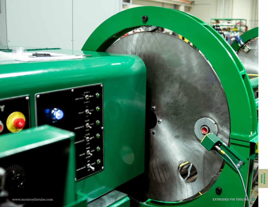
TOOLING EXTRUDED FIN
www.mcelroyfintube.com
EXTRU
DED
TOO
LING
EXTRUDED FIN TOOLING 117
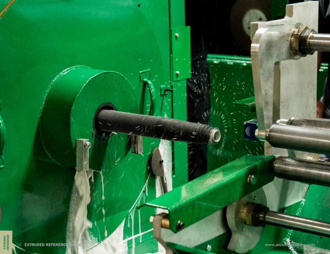
EXTRUDED REFERENCE GUIDE
www.mcelroyfintube.com
EXTR
UD
EDR
EFER
ENCE
118 EXTRUDED REFERENCE GUIDE

REFERENCE GUIDE EXTRUDEDEXTRUDED REFERENCE GUIDE
EXTRUDED MACHINEREFERENCE GUIDE
www.mcelroyfintube.com
EXTRU
DED
REFER
ENCE
EXTRUDED REFERENCE GUIDE 119
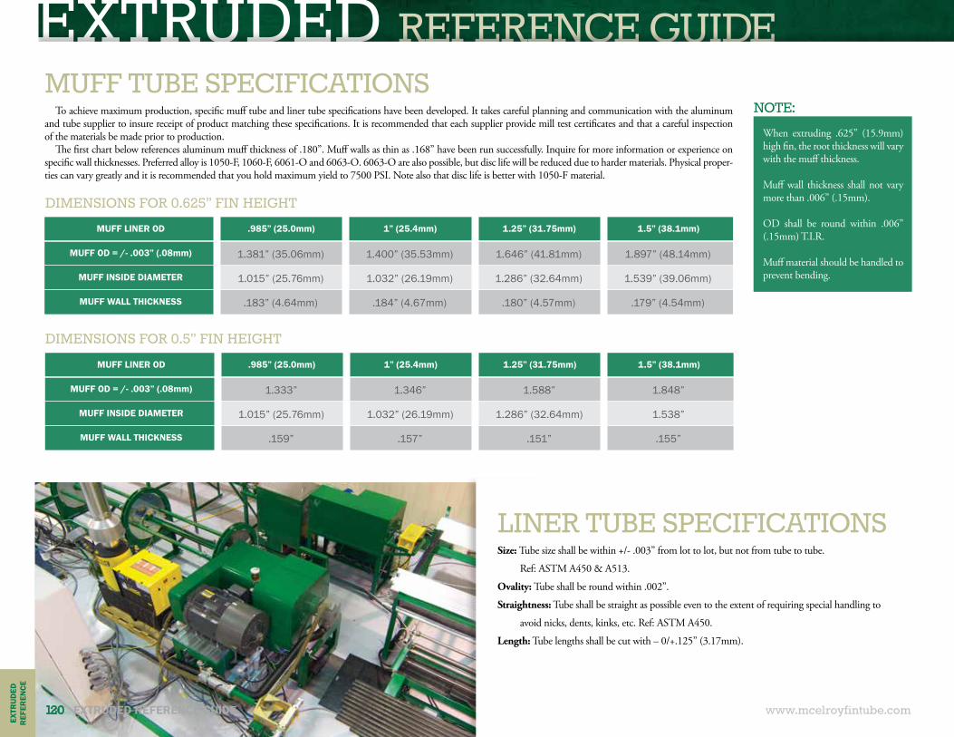
EXTRUDED REFERENCE GUIDE
www.mcelroyfintube.com
EXTR
UD
EDR
EFER
ENCE
120 EXTRUDED REFERENCE GUIDE
MUFF TUBE SPECIFICATIONSNOTE:
LINER TUBE SPECIFICATIONS
To achieve maximum production, specific muff tube and liner tube specifications have been developed. It takes careful planning and communication with the aluminum and tube supplier to insure receipt of product matching these specifications. It is recommended that each supplier provide mill test certificates and that a careful inspection of the materials be made prior to production.
The first chart below references aluminum muff thickness of .180”. Muff walls as thin as .168” have been run successfully. Inquire for more information or experience on specific wall thicknesses. Preferred alloy is 1050-F, 1060-F, 6061-O and 6063-O. 6063-O are also possible, but disc life will be reduced due to harder materials. Physical proper-ties can vary greatly and it is recommended that you hold maximum yield to 7500 PSI. Note also that disc life is better with 1050-F material.
Size: Tube size shall be within +/- .003” from lot to lot, but not from tube to tube.
Ref: ASTM A450 & A513.
Ovality: Tube shall be round within .002”.
Straightness: Tube shall be straight as possible even to the extent of requiring special handling to
avoid nicks, dents, kinks, etc. Ref: ASTM A450.
Length: Tube lengths shall be cut with – 0/+.125” (3.17mm).
When extruding .625” (15.9mm) high fin, the root thickness will vary with the muff thickness.
Muff wall thickness shall not vary more than .006” (.15mm).
OD shall be round within .006” (.15mm) T.I.R.
Muff material should be handled to prevent bending.
MUFF LINER OD .985” (25.0mm) 1” (25.4mm) 1.25” (31.75mm) 1.5” (38.1mm)
MUFF OD = /- .003” (.08mm) 1.381” (35.06mm) 1.400” (35.53mm) 1.646” (41.81mm) 1.897” (48.14mm)
MUFF INSIDE DIAMETER 1.015” (25.76mm) 1.032” (26.19mm) 1.286” (32.64mm) 1.539” (39.06mm)
MUFF WALL THICKNESS .183” (4.64mm) .184” (4.67mm) .180” (4.57mm) .179” (4.54mm)
MUFF LINER OD .985” (25.0mm) 1” (25.4mm) 1.25” (31.75mm) 1.5” (38.1mm)
MUFF OD = /- .003” (.08mm) 1.333” 1.346” 1.588” 1.848”
MUFF INSIDE DIAMETER 1.015” (25.76mm) 1.032” (26.19mm) 1.286” (32.64mm) 1.538”
MUFF WALL THICKNESS .159” .157” .151” .155”
DIMENSIONS FOR 0.625” FIN HEIGHT
DIMENSIONS FOR 0.5” FIN HEIGHT
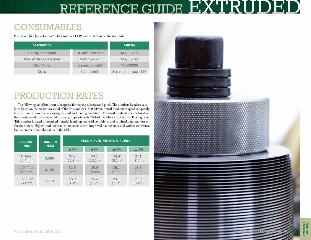
REFERENCE GUIDE EXTRUDED
www.mcelroyfintube.com
EXTRU
DED
REFER
ENCE
EXTRUDED REFERENCE GUIDE 121
PRODUCTION RATESThe following table lists linear tube speeds for varying tube size and pitch. The numbers listed are calcu-
lated based on the maximum speed of the drive motor (1800 RPM). Actual production speed is typically less than maximum due to varying material and tooling conditions. Nominal production rates based on linear tube speed can be expected to average approximately 70% of the values listed in the following table. This number is based on required material handling, material conditions, and minimal wear and tear on the machinery. Higher production rates are possible with improved maintenance and worker experience but will never exceed the values in the table.
TUBE OD(mm)
TUBE RPM (MAX)
FEET/MINUTE (METERS/MINUTES)
8 FPI 9 FPI 10 FPI 11 FPI
1” Tube (25.4mm) 3,585 37.2’
(11.3m)33.1’
(10.1m)29.9’
(9.1m)27.1’
(8.2m)
1.25” Tube (31.7mm) 3,128 32.6’
(9.9m)28.9’
(8.8m)26.1’ (7.9m)
23.6’ (7.2m)
1.5” Tube (38.1mm) 2,779 28.9’
(8.8m)25.6’ (7.8m)
23.1’ (7.0m)
21.0’ (6.4m)
CONSUMABLES
DESCRIPTION PART NO.
Finning Compound 10 Gallon per shift MJQ00212
Tube Washing Detergent 1 Gallon per shift MJQ00209
Filter Paper 8 Yards per shift MED00038
Discs 3.2 per shift See chart on page 116
Based on 6,645 linear feet on 50 foot tube at 11 FPI with an 8 hour production shift.
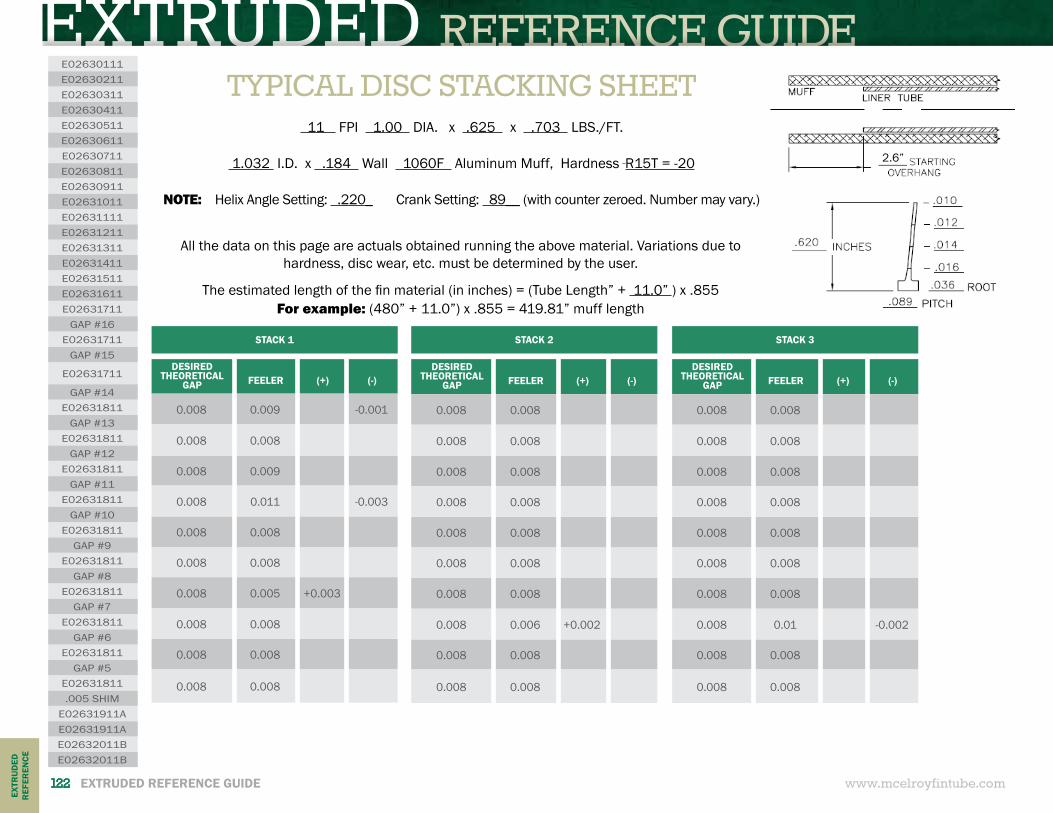
EXTRUDED REFERENCE GUIDE
www.mcelroyfintube.com
EXTR
UD
EDR
EFER
ENCE
122 EXTRUDED REFERENCE GUIDE
TYPICAL DISC STACKING SHEET 11 FPI 1.00 DIA. x .625 x .703 LBS./FT.
1.032 I.D. x .184 Wall 1060F Aluminum Muff, Hardness R15T = -20
NOTE: Helix Angle Setting: .220_ Crank Setting: 89__ (with counter zeroed. Number may vary.)
DESIRED THEORETICAL
GAP
FEELER
(+)
(-)
0.008 0.009 -0.001
0.008 0.008
0.008 0.009
0.008 0.011 -0.003
0.008 0.008
0.008 0.008
0.008 0.005 +0.003
0.008 0.008
0.008 0.008
0.008 0.008
DESIRED THEORETICAL
GAP
FEELER
(+)
(-)
0.008 0.008
0.008 0.008
0.008 0.008
0.008 0.008
0.008 0.008
0.008 0.008
0.008 0.008
0.008 0.006 +0.002
0.008 0.008
0.008 0.008
DESIRED THEORETICAL
GAP
FEELER
(+)
(-)
0.008 0.008
0.008 0.008
0.008 0.008
0.008 0.008
0.008 0.008
0.008 0.008
0.008 0.008
0.008 0.01 -0.002
0.008 0.008
0.008 0.008
STACK 1 STACK 2 STACK 3
E02630111E02630211E02630311E02630411E02630511E02630611E02630711E02630811E02630911E02631011E02631111E02631211E02631311E02631411E02631511E02631611E02631711
GAP #16E02631711
GAP #15
E02631711
GAP #14E02631811
GAP #13E02631811
GAP #12E02631811
GAP #11E02631811
GAP #10E02631811
GAP #9E02631811
GAP #8E02631811
GAP #7E02631811
GAP #6E02631811
GAP #5E02631811.005 SHIM
E02631911AE02631911AE02632011BE02632011B
All the data on this page are actuals obtained running the above material. Variations due to hardness, disc wear, etc. must be determined by the user.
The estimated length of the fin material (in inches) = (Tube Length” + 11.0” ) x .855For example: (480” + 11.0”) x .855 = 419.81” muff length
2.6”
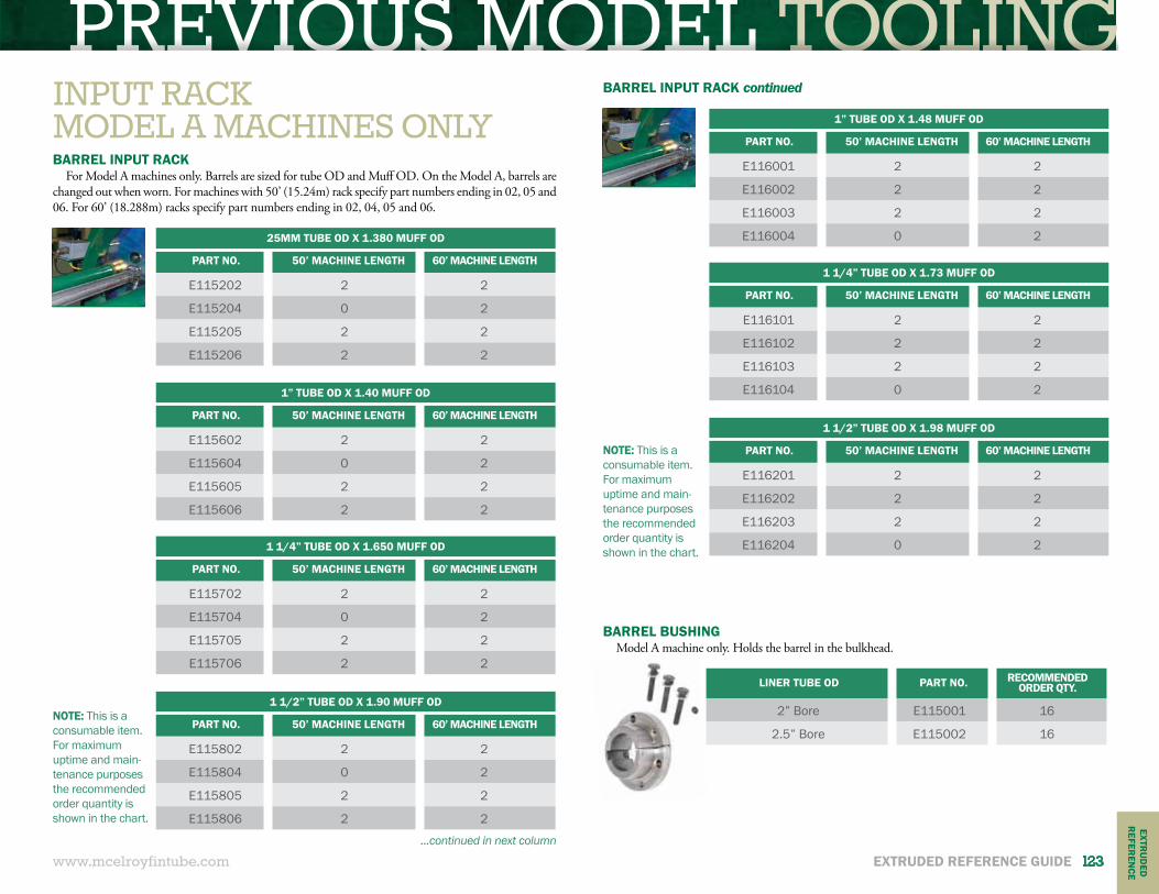
PREVIOUS MODEL TOOLING
www.mcelroyfintube.com
EXTRU
DED
REFER
ENCE
EXTRUDED REFERENCE GUIDE 123
BARREL INPUT RACKFor Model A machines only. Barrels are sized for tube OD and Muff OD. On the Model A, barrels are
changed out when worn. For machines with 50’ (15.24m) rack specify part numbers ending in 02, 05 and 06. For 60’ (18.288m) racks specify part numbers ending in 02, 04, 05 and 06.
BARREL BUSHINGModel A machine only. Holds the barrel in the bulkhead.
25MM TUBE OD X 1.380 MUFF OD
PART NO. 50’ MACHINE LENGTH 60’ MACHINE LENGTH
E115202 2 2
E115204 0 2
E115205 2 2
E115206 2 2
1” TUBE OD X 1.40 MUFF OD
PART NO. 50’ MACHINE LENGTH 60’ MACHINE LENGTH
E115602 2 2
E115604 0 2
E115605 2 2
E115606 2 2
1” TUBE OD X 1.48 MUFF OD
PART NO. 50’ MACHINE LENGTH 60’ MACHINE LENGTH
E116001 2 2
E116002 2 2
E116003 2 2
E116004 0 2
1 1/4” TUBE OD X 1.650 MUFF OD
PART NO. 50’ MACHINE LENGTH 60’ MACHINE LENGTH
E115702 2 2
E115704 0 2
E115705 2 2
E115706 2 2
1 1/4” TUBE OD X 1.73 MUFF OD
PART NO. 50’ MACHINE LENGTH 60’ MACHINE LENGTH
E116101 2 2
E116102 2 2
E116103 2 2
E116104 0 2
1 1/2” TUBE OD X 1.90 MUFF OD
PART NO. 50’ MACHINE LENGTH 60’ MACHINE LENGTH
E115802 2 2
E115804 0 2
E115805 2 2
E115806 2 2
1 1/2” TUBE OD X 1.98 MUFF OD
PART NO. 50’ MACHINE LENGTH 60’ MACHINE LENGTH
E116201 2 2
E116202 2 2
E116203 2 2
E116204 0 2
NOTE: This is a consumable item. For maximum uptime and main-tenance purposes the recommended order quantity is shown in the chart.
NOTE: This is a consumable item. For maximum uptime and main-tenance purposes the recommended order quantity is shown in the chart.
BARREL INPUT RACK continued
...continued in next column
LINER TUBE OD PART NO. RECOMMENDED ORDER QTY.
2” Bore E115001 16
2.5” Bore E115002 16
INPUT RACKMODEL A MACHINES ONLY
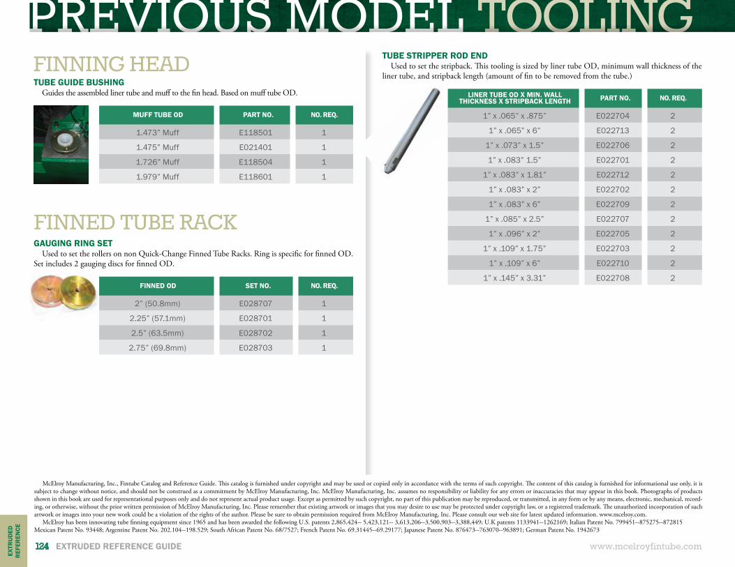
PREVIOUS MODEL TOOLING
www.mcelroyfintube.com124 EXTRUDED REFERENCE GUIDE
EXTR
UD
EDR
EFER
ENCE
FINNING HEADTUBE GUIDE BUSHING
Guides the assembled liner tube and muff to the fin head. Based on muff tube OD.
MUFF TUBE OD PART NO. NO. REQ.
1.473” Muff E118501 1
1.475” Muff E021401 1
1.726” Muff E118504 1
1.979” Muff E118601 1
FINNED TUBE RACKGAUGING RING SET
Used to set the rollers on non Quick-Change Finned Tube Racks. Ring is specific for finned OD. Set includes 2 gauging discs for finned OD.
FINNED OD SET NO. NO. REQ.
2” (50.8mm) E028707 1
2.25” (57.1mm) E028701 1
2.5” (63.5mm) E028702 1
2.75” (69.8mm) E028703 1
TUBE STRIPPER ROD ENDUsed to set the stripback. This tooling is sized by liner tube OD, minimum wall thickness of the
liner tube, and stripback length (amount of fin to be removed from the tube.)
LINER TUBE OD X MIN. WALLTHICKNESS X STRIPBACK LENGTH PART NO. NO. REQ.
1” x .065” x .875” E022704 2
1” x .065” x 6” E022713 2
1” x .073” x 1.5” E022706 2
1” x .083” 1.5” E022701 2
1” x .083” x 1.81” E022712 2
1” x .083” x 2” E022702 2
1” x .083” x 6” E022709 2
1” x .085” x 2.5” E022707 2
1” x .096” x 2” E022705 2
1” x .109” x 1.75” E022703 2
1” x .109” x 6” E022710 2
1” x .145” x 3.31” E022708 2
McElroy Manufacturing, Inc., Fintube Catalog and Reference Guide. This catalog is furnished under copyright and may be used or copied only in accordance with the terms of such copyright. The content of this catalog is furnished for informational use only, it is subject to change without notice, and should not be construed as a commitment by McElroy Manufacturing, Inc. McElroy Manufacturing, Inc. assumes no responsibility or liability for any errors or inaccuracies that may appear in this book. Photographs of products shown in this book are used for representational purposes only and do not represent actual product usage. Except as permitted by such copyright, no part of this publication may be reproduced, or transmitted, in any form or by any means, electronic, mechanical, record-ing, or otherwise, without the prior written permission of McElroy Manufacturing, Inc. Please remember that existing artwork or images that you may desire to use may be protected under copyright law, or a registered trademark. The unauthorized incorporation of such artwork or images into your new work could be a violation of the rights of the author. Please be sure to obtain permission required from McElroy Manufacturing, Inc. Please consult our web site for latest updated information. www.mcelroy.com.
McElroy has been innovating tube finning equipment since 1965 and has been awarded the following U.S. patents 2,865,424-- 5,423,121-- 3,613,206--3,500,903--3,388,449; U.K patents 1133941--1262169; Italian Patent No. 799451--875275--872815Mexican Patent No. 93448; Argentine Patent No. 202.104--198.529; South African Patent No. 68/7527; French Patent No. 69.31445--69.29177; Japanese Patent No. 876473--763070--963891; German Patent No. 1942673

NOTES
www.mcelroyfintube.com NOTES 125

NOTES
www.mcelroyfintube.com126 NOTES

NOTES
www.mcelroyfintube.com NOTES 127
P.O. BOX 580550 TULSA, OK 74158-0550 U.S.A.918-831-9236 www.mcelroyfintube.com
Copyright © 2016 McElroy Manufacturing, Inc. Catalog No. CTLGFIN0616. Printed in the U.S.A.