Embed Size (px)
Citation preview
Drives Solutions
www.danfoss.com/drives
Operating Instructions
MCD Remote Operator
Soft StarterSoft Starter
Operating Instructions
175R0964 MG15D202
XREF__BCNOT LOADED ON RIP
*MG15D202*REV. 2003-07-21
Soft Starter Remote Operator
MG.15.D2.02 – VLT is a registered Danfoss trademark 1
Co
ntents
Section 1.0 ■ Introduction 1.1 Important user information .............................. 2 1.2 General ........................................................... 2 1.3 Manual description ...........................................2
Section 2.0 ■ Specification
2.1 General technical data .....................................3 2.2 Dimensions ......................................................3
Section 3.0 ■ Basic Set Up
3.1 Definition ........................................................4 3.2 Mounting .......................................................4 3.3 Electrical connection ......................................4 3.4 Front panel operation.......................................5
Section 4.0 ■ Advanced Set Up
4.1 Definition..........................................................6 4.2 Installation sequence .......................................6 4.3 Mounting .........................................................6 4.4 Electrical connection........................................7 4.5 Soft starter compatibility ..................................7 4.6 Configuring the soft starter...............................8 4.7 Configuring the Remote Operator ....................8
Section 5.0 ■ Operation & Programming 5.1 Front panel operation .................................... 9 5.2 Programming ............................................. 10 5.3 RS485 serial communication .......................12 5.4 4-20 mA analogue output ............................19
Section 6.0 ■ Trouble Shooting
6.1 General faults .............................................. 20 6.2 Trip codes ...................................................21
Soft Starter Remote Operator
2 MG.15.D2.02 – VLT is a registered Danfoss trademark
Intr
od
ucti
on 1.1 Important
User Information The Remote Operator allows remote operation of the soft starter. Observe all necessary safety precautions when controlling the soft starter remotely. Alert personnel that machinery may start without warning. It is the installer’s responsibility to follow all instructions in this manual and to follow correct electrical practice. Use all International recognised standard practice for RS485 communications when installing and using this equipment.
Users are cautioned that the information contained in this manual is subject to change at any time
and without prior notice. In no event will responsibility or liability be accepted for direct, indirect or
consequential damages resulting from the use or application of this equipment.
1.2 General The Remote Operator incorporates an RS485 serial communications facility which allows the remote control of a motor in the same way as the soft starter control function. It also acts as a gateway device for connection to an RS485 serial communications network. This allows for remote control of a motor from an RS485 serial communications network using Modbus RTU or standard AP ASCII communications protocol. These protocols are selectable. With the Remote Operator you can start, stop, quick stop and reset trip conditions and read operational status and motor data, ie, motor current, motor temperature and trip status. There is also a 4-20 mA analogue output for motor current monitoring. The Remote Operator is rated IP54 or NEMA 12 when installed as per instructions detailed in Sections 4.2 and 4.3 of this manual.
1.3. Manual Description This manual describes the installation, connection, configuration and operation of the
Remote Operator. For details on soft starter compatibility refer to Section 4.5 of this manual. Reference must be made to the MCD3000 Operating Instructions and the MCD201/202 Users Manual where stated. Indicates something to be noted by reader Indicates a general warning
Soft Starter Remote Operator
MG.15.D2.02 – VLT is a registered Danfoss trademark 3
Sp
ecification
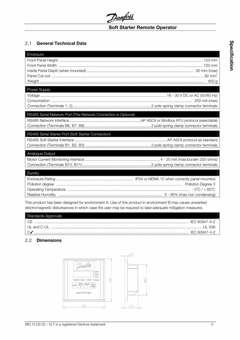
2.1 General Technical Data
Enclosure
Front Panel Height ...................................................................................................................................... 120 mmFront Panel Width ....................................................................................................................................... 120 mmInside Panel Depth (when mounted) .................................................................................................... 30 mm (max)Panel Cut-out ................................................................................................................................................92 mm2
Weight ........................................................................................................................................................... 450 g
Power Supply
Voltage ...................................................................................................................... 18 - 30 V DC or AC (50/60 Hz) Consumption .................................................................................................................................... 250 mA (max) Connection (Terminals 1, 2)..........................................................................2 pole spring clamp connector terminals
RS485 Serial Network Port (This Network Connection is Optional)
RS485 Network Interface...................................................................AP ASCII or Modbus RTU protocol (selectable) Connection (Terminals B6, B7, B8) ..............................................................3 pole spring clamp connector terminals
RS485 Serial Starter Port (Soft Starter Connection)
RS485 Soft Starter Interface ...................................................................................... AP ASCII protocol as standard Connection (Terminals B1, B2, B3) ..............................................................3 pole spring clamp connector terminals
Analogue Output
Motor Current Monitoring Interface ...................................................................... 4 - 20 mA (max.burden 200 ohms) Connection (Terminals B10, B11).................................................................2 pole spring clamp connector terminals
Sundry
Enclosure Rating......................................................................... IP54 or NEMA 12 when correctly panel mounted Pollution degree ...................................................................................................................... Pollution Degree 3 Operating Temperature .................................................................................................................. - 5oC / + 60oC Relative Humidity ................................................................................................. 5 - 95% (max non condensing)
This product has been designed for environment A. Use of this product in environment B may cause unwanted electromagnetic disturbances in which case the user may be required to take adequate mitigation measures.
Standards Approvals
CE ............................................................................................................................................... IEC 60947-4-2 UL and C-UL .............................................................................................................................................. UL 508 C� ................................................................................................................................................. IEC 60947-4-2
2.2 Dimensions
Soft Starter Remote Operator
4 MG.15.D2.02 – VLT is a registered Danfoss trademark
Bas
ic S
et U
p 3.1 Definition If the Remote Operator is only being used with a soft starter, use the procedure detailed in this section. The Remote Operator is pre-configured to control a soft starter once control supply power is applied to these devices. No parameter adjustments are required to the Remote Operator or soft starter for basic operation.
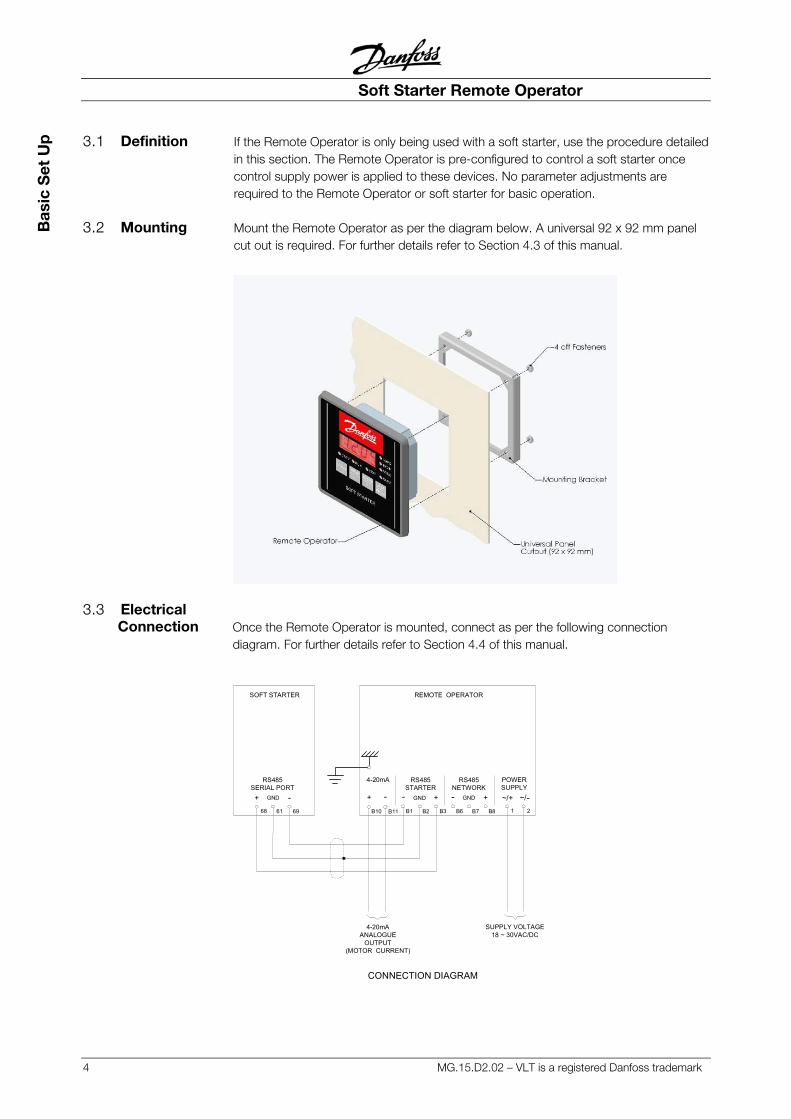
3.2 Mounting Mount the Remote Operator as per the diagram below. A universal 92 x 92 mm panel cut out is required. For further details refer to Section 4.3 of this manual.
3.3 Electrical
Connection Once the Remote Operator is mounted, connect as per the following connection diagram. For further details refer to Section 4.4 of this manual.
68 61 69 1 2B1 B2 B3 B6 B7 B8B10 B11
SOFT STARTER REMOTE OPERATOR
4-20mAANALOGUE
OUTPUT(MOTOR CURRENT)
SUPPLY VOLTAGE18 ~ 30VAC/DC
GND +-GND +-+ GND - ~/+-+ ~/-
CONNECTION DIAGRAM
RS485SERIAL PORT
4-20mA RS485STARTER
RS485NETWORK
POWERSUPPLY
Soft Starter Remote Operator
MG.15.D2.02 – VLT is a registered Danfoss trademark 5
Basic S
et Up
3.4 Front Panel Operation
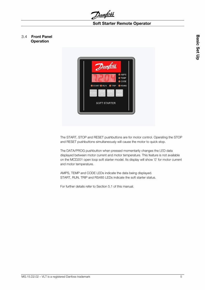
The START, STOP and RESET pushbuttons are for motor control. Operating the STOP and RESET pushbuttons simultaneously will cause the motor to quick stop. The DATA/PROG pushbutton when pressed momentarily changes the LED data displayed between motor current and motor temperature. This feature is not available on the MCD201 open loop soft starter model. Its display will show `0’ for motor current and motor temperature. AMPS, TEMP and CODE LEDs indicate the data being displayed. START, RUN, TRIP and RS485 LEDs indicate the soft starter status. For further details refer to Section 5.1 of this manual.
Soft Starter Remote Operator
6 MG.15.D2.02 – VLT is a registered Danfoss trademark
Ad
vanc
ed S
et U
p 4.1 Definition The Remote Operator can be connected to an RS485 serial communications network using AP ASCII or Modbus RTU selectable protocol. It also has a 4-20 mA analogue output for motor current monitoring. If these features are being used refer to the following details in this section.
4.2 Installation Sequence To install the Remote Operator use the following procedure.
�� Mount the Remote Operator at its intended location �� Connect the external power supply to the Remote Operator
and the soft starter �� Connect the Remote Operator RS485 Starter port to the soft starter �� Connect the Remote Operator RS485 Network port to a serial
communications network �� Configure the soft starter �� Configure the Remote Operator
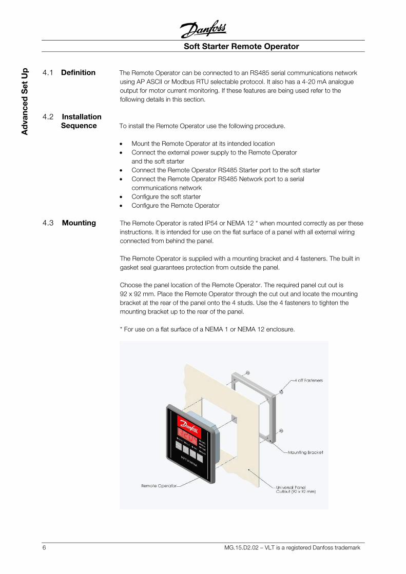
4.3 Mounting The Remote Operator is rated IP54 or NEMA 12 * when mounted correctly as per these instructions. It is intended for use on the flat surface of a panel with all external wiring connected from behind the panel. The Remote Operator is supplied with a mounting bracket and 4 fasteners. The built in gasket seal guarantees protection from outside the panel. Choose the panel location of the Remote Operator. The required panel cut out is 92 x 92 mm. Place the Remote Operator through the cut out and locate the mounting bracket at the rear of the panel onto the 4 studs. Use the 4 fasteners to tighten the mounting bracket up to the rear of the panel. * For use on a flat surface of a NEMA 1 or NEMA 12 enclosure.
Soft Starter Remote Operator
MG.15.D2.02 – VLT is a registered Danfoss trademark 7
Ad
vanced S
et Up
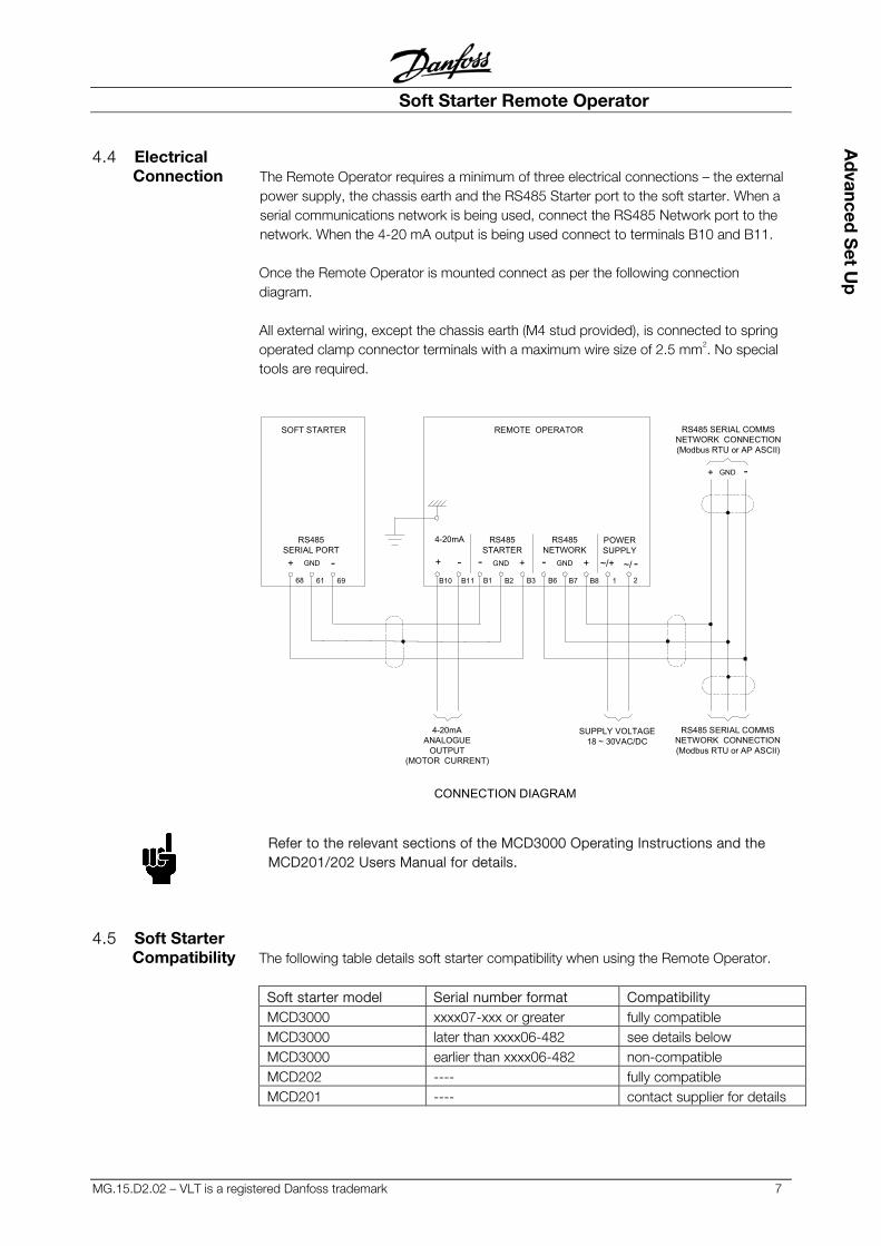
4.4 Electrical Connection The Remote Operator requires a minimum of three electrical connections – the external
power supply, the chassis earth and the RS485 Starter port to the soft starter. When a serial communications network is being used, connect the RS485 Network port to the network. When the 4-20 mA output is being used connect to terminals B10 and B11. Once the Remote Operator is mounted connect as per the following connection diagram. All external wiring, except the chassis earth (M4 stud provided), is connected to spring operated clamp connector terminals with a maximum wire size of 2.5 mm2. No special tools are required.
68 61 69 B10 B11 B1 B2 B3 B6 B7 B8 1 2
SOFT STARTER REMOTE OPERATOR RS485 SERIAL COMMSNETWORK CONNECTION(Modbus RTU or AP ASCII)
RS485 SERIAL COMMSNETWORK CONNECTION(Modbus RTU or AP ASCII)
4-20mAANALOGUE
OUTPUT(MOTOR CURRENT)
SUPPLY VOLTAGE18 ~ 30VAC/DC
+ GND -
GND +-GND +-+ GND - ~/+-+ ~/ -
CONNECTION DIAGRAM
RS485SERIAL PORT
4-20mA RS485STARTER
RS485NETWORK
POWERSUPPLY
Refer to the relevant sections of the MCD3000 Operating Instructions and the MCD201/202 Users Manual for details.
4.5 Soft Starter Compatibility The following table details soft starter compatibility when using the Remote Operator.
Soft starter model Serial number format Compatibility MCD3000 xxxx07-xxx or greater fully compatible MCD3000 later than xxxx06-482 see details below MCD3000 earlier than xxxx06-482 non-compatible MCD202 ---- fully compatible MCD201 ---- contact supplier for details
Soft Starter Remote Operator
8 MG.15.D2.02 – VLT is a registered Danfoss trademark
Ad
vanc
ed S
et U
p MCD3000 models identified by unit serial numbers later than xxxx06-482 are limited such that; �� The Forced Communications Trip feature (display code H) is not available when
networking. �� MCD3000 trip codes C (RS485 Comms Fault) and L (FLC Range Error) are
displayed as 1- on the Remote Operator. These trip codes are displayed correctly on the soft starter front panel.
Consult your local supplier if the Remote Operator is to be used with a non-compatible soft starter.
4.6 Configuring the Soft Starter No soft starter configuration is required unless RS485 Time Out protection between the
Remote Operator and soft starter is being used. The Remote Operator to soft starter Baud Rate (9,600 baud) and Satellite Address (20) are fixed within the Remote Operator. These parameters are default set within the soft starter. The soft starter should be set for local operation only when using the Remote Operator. For soft starter configuration details and set up procedures refer to the MCD3000 Operating Instructions and the MCD201/202 Users Manual.
4.7 Configuring the Remote Operator
If the Remote Operator is not being used with a serial communications network no configuration of the Remote Operator is necessary unless the 4-20 mA analogue output is required.
When configuring the Remote Operator it must be powered up with the soft starter in the “off” mode. When the Remote Operator is being used with a serial communications network configure the Remote Operator RS485 Network Baud Rate and Satellite Address to match that of the network. The Remote Operator RS485 Network Time Out protects the link between the Remote Operator and the serial communications network. Set this as required. The Remote Operator to serial communications network protocol is default set for AP ASCII. This can be selected to Modbus RTU protocol. Set as required along with the Modbus Parity if applicable. When the Remote Operator 4-20mA analogue output is being used set the Motor FLC and Analogue Output 4mA Offset parameters to suit the application. Refer to parameter list and programming procedure in Section 5.2 of this manual.
Soft Starter Remote Operator
MG.15.D2.02 – VLT is a registered Danfoss trademark 9
Ad
vanced S
et Up
5.1 Front Panel Operation The Remote Operator performs all soft starter functions except programming of the soft
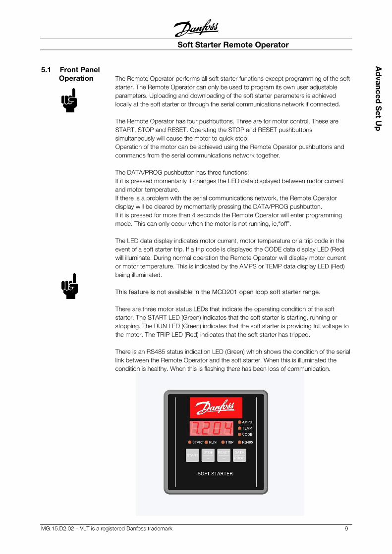
starter. The Remote Operator can only be used to program its own user adjustable parameters. Uploading and downloading of the soft starter parameters is achieved locally at the soft starter or through the serial communications network if connected. The Remote Operator has four pushbuttons. Three are for motor control. These are START, STOP and RESET. Operating the STOP and RESET pushbuttons simultaneously will cause the motor to quick stop. Operation of the motor can be achieved using the Remote Operator pushbuttons and commands from the serial communications network together. The DATA/PROG pushbutton has three functions: If it is pressed momentarily it changes the LED data displayed between motor current and motor temperature. If there is a problem with the serial communications network, the Remote Operator display will be cleared by momentarily pressing the DATA/PROG pushbutton. If it is pressed for more than 4 seconds the Remote Operator will enter programming mode. This can only occur when the motor is not running, ie,“off”. The LED data display indicates motor current, motor temperature or a trip code in the event of a soft starter trip. If a trip code is displayed the CODE data display LED (Red) will illuminate. During normal operation the Remote Operator will display motor current or motor temperature. This is indicated by the AMPS or TEMP data display LED (Red) being illuminated. This feature is not available in the MCD201 open loop soft starter range. There are three motor status LEDs that indicate the operating condition of the soft starter. The START LED (Green) indicates that the soft starter is starting, running or stopping. The RUN LED (Green) indicates that the soft starter is providing full voltage to the motor. The TRIP LED (Red) indicates that the soft starter has tripped. There is an RS485 status indication LED (Green) which shows the condition of the serial link between the Remote Operator and the soft starter. When this is illuminated the condition is healthy. When this is flashing there has been loss of communication.
Soft Starter Remote Operator
10 MG.15.D2.02 – VLT is a registered Danfoss trademark
Op
erat
ion
& P
rog
ram
min
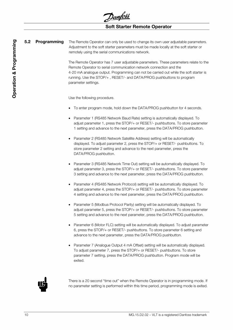
g 5.2 Programming The Remote Operator can only be used to change its own user adjustable parameters. Adjustment to the soft starter parameters must be made locally at the soft starter or remotely using the serial communications network.
The Remote Operator has 7 user adjustable parameters. These parameters relate to the Remote Operator to serial communication network connection and the 4-20 mA analogue output. Programming can not be carried out while the soft starter is running. Use the STOP/+ , RESET/- and DATA/PROG pushbuttons to program parameter settings. Use the following procedure. �� To enter program mode, hold down the DATA/PROG pushbutton for 4 seconds. �� Parameter 1 (RS485 Network Baud Rate) setting is automatically displayed. To
adjust parameter 1, press the STOP/+ or RESET/- pushbuttons. To store parameter 1 setting and advance to the next parameter, press the DATA/PROG pushbutton.
�� Parameter 2 (RS485 Network Satellite Address) setting will be automatically displayed. To adjust parameter 2, press the STOP/+ or RESET/- pushbuttons. To store parameter 2 setting and advance to the next parameter, press the DATA/PROG pushbutton.
�� Parameter 3 (RS485 Network Time Out) setting will be automatically displayed. To adjust parameter 3, press the STOP/+ or RESET/- pushbuttons. To store parameter 3 setting and advance to the next parameter, press the DATA/PROG pushbutton.
�� Parameter 4 (RS485 Network Protocol) setting will be automatically displayed. To adjust parameter 4, press the STOP/+ or RESET/- pushbuttons. To store parameter 4 setting and advance to the next parameter, press the DATA/PROG pushbutton.
�� Parameter 5 (Modbus Protocol Parity) setting will be automatically displayed. To adjust parameter 5, press the STOP/+ or RESET/- pushbuttons. To store parameter 5 setting and advance to the next parameter, press the DATA/PROG pushbutton.
�� Parameter 6 (Motor FLC) setting will be automatically displayed. To adjust parameter 6, press the STOP/+ or RESET/- pushbuttons. To store parameter 6 setting and advance to the next parameter, press the DATA/PROG pushbutton.
�� Parameter 7 (Analogue Output 4 mA Offset) setting will be automatically displayed. To adjust parameter 7, press the STOP/+ or RESET/- pushbuttons. To store parameter 7 setting, press the DATA/PROG pushbutton. Program mode will be exited.
There is a 20 second “time out” when the Remote Operator is in programming mode. If no parameter setting is performed within this time period, programming mode is exited.
Soft Starter Remote Operator
MG.15.D2.02 – VLT is a registered Danfoss trademark 11
Ad
vanced S
et Up
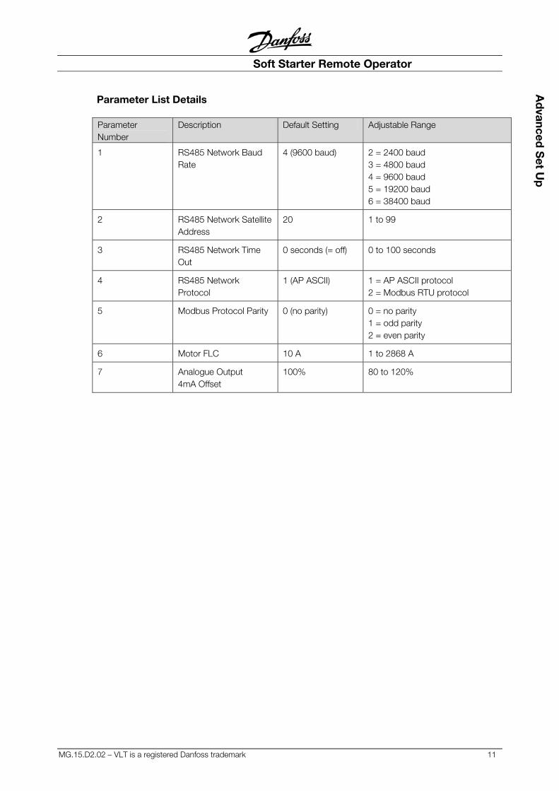
Parameter List Details Parameter Number
Description Default Setting Adjustable Range
1 RS485 Network Baud Rate
4 (9600 baud) 2 = 2400 baud 3 = 4800 baud 4 = 9600 baud 5 = 19200 baud 6 = 38400 baud
2 RS485 Network Satellite Address
20 1 to 99
3 RS485 Network Time Out
0 seconds (= off) 0 to 100 seconds
4 RS485 Network Protocol
1 (AP ASCII) 1 = AP ASCII protocol 2 = Modbus RTU protocol
5 Modbus Protocol Parity 0 (no parity) 0 = no parity 1 = odd parity 2 = even parity
6 Motor FLC 10 A 1 to 2868 A
7 Analogue Output 4mA Offset
100% 80 to 120%
Soft Starter Remote Operator
12 MG.15.D2.02 – VLT is a registered Danfoss trademark
Op
erat
ion
& P
rog
ram
min
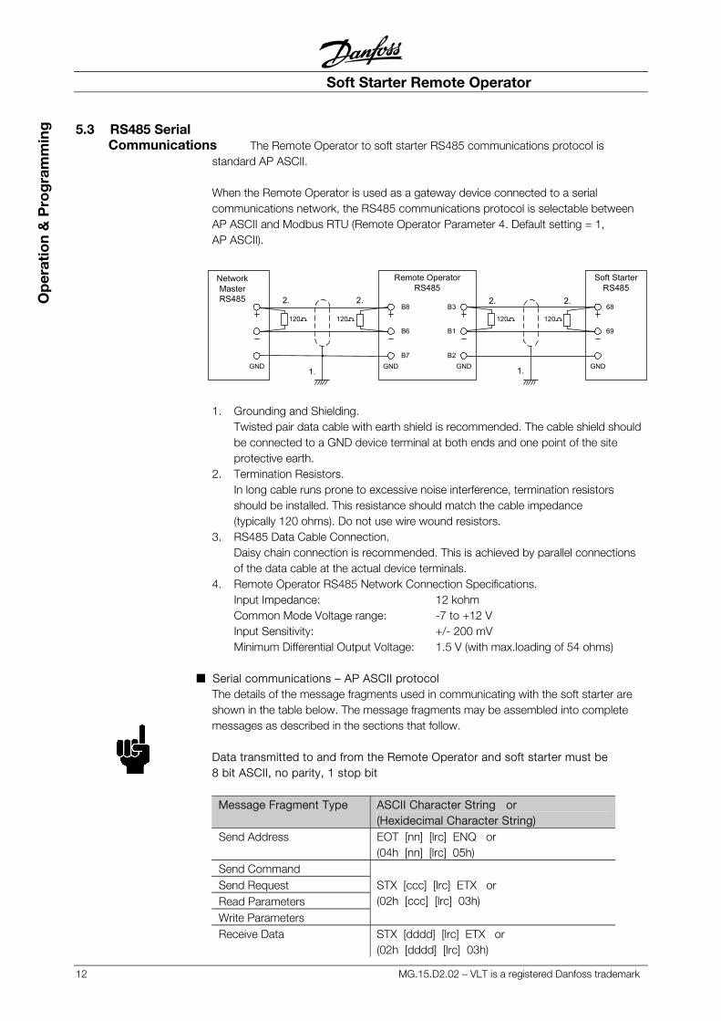
g 5.3 RS485 Serial Communications The Remote Operator to soft starter RS485 communications protocol is
standard AP ASCII. When the Remote Operator is used as a gateway device connected to a serial communications network, the RS485 communications protocol is selectable between AP ASCII and Modbus RTU (Remote Operator Parameter 4. Default setting = 1, AP ASCII).
1. Grounding and Shielding.
Twisted pair data cable with earth shield is recommended. The cable shield should be connected to a GND device terminal at both ends and one point of the site protective earth.
2. Termination Resistors. In long cable runs prone to excessive noise interference, termination resistors should be installed. This resistance should match the cable impedance (typically 120 ohms). Do not use wire wound resistors.
3. RS485 Data Cable Connection. Daisy chain connection is recommended. This is achieved by parallel connections of the data cable at the actual device terminals.
4. Remote Operator RS485 Network Connection Specifications. Input Impedance: 12 kohm Common Mode Voltage range: -7 to +12 V Input Sensitivity: +/- 200 mV Minimum Differential Output Voltage: 1.5 V (with max.loading of 54 ohms)
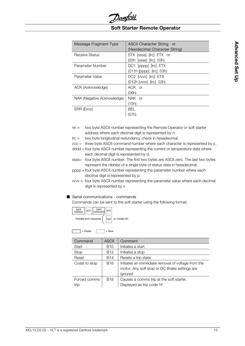
■ Serial communications – AP ASCII protocol
The details of the message fragments used in communicating with the soft starter are shown in the table below. The message fragments may be assembled into complete messages as described in the sections that follow. Data transmitted to and from the Remote Operator and soft starter must be 8 bit ASCII, no parity, 1 stop bit
Message Fragment Type ASCII Character String or (Hexidecimal Character String)
Send Address EOT [nn] [lrc] ENQ or (04h [nn] [lrc] 05h)
Send Command Send Request Read Parameters Write Parameters
STX [ccc] [lrc] ETX or (02h [ccc] [lrc] 03h)
Receive Data STX [dddd] [lrc] ETX or (02h [dddd] [lrc] 03h)
120 120 120 120
2. 2. 2. 2.
1. 1.
NetworkMasterRS485
Remote OperatorRS485
Soft StarterRS485
GND
B8
B6
B7
B3
B1
B2
68
69
GND GND GND
Soft Starter Remote Operator
MG.15.D2.02 – VLT is a registered Danfoss trademark 13
Ad
vanced S
et Up
Message Fragment Type ASCII Character String or (Hexidecimal Character String)
Receive Status STX [ssss] [lrc] ETX or (02h [ssss] [lrc] 03h)
Parameter Number DC1 [pppp] [lrc] ETX (011h [pppp] [lrc] 03h)
Parameter Value DC2 [vvvv] [lrc] ETX (012h [vvvv] [lrc] 03h)
ACK (Acknowledge) ACK or (06h)
NAK (Negative Acknowledge) NAK or (15h)
ERR (Error) BEL (07h)
nn = two byte ASCII number representing the Remote Operator or soft starter address where each decimal digit is represented by n.
lrc = two byte longitudinal redundancy check in hexadecimal. ccc = three byte ASCII command number where each character is represented by c. dddd = four byte ASCII number representing the current or temperature data where
each decimal digit is represented by d. ssss= four byte ASCII number. The first two bytes are ASCII zero. The last two bytes
represent the nibbles of a single byte of status data in hexadecimal. pppp = four byte ASCII number representing the parameter number where each
decimal digit is represented by p. vvvv = four byte ASCII number representing the parameter value where each decimal
digit is represented by v.
■ Serial communications - commands Commands can be sent to the soft starter using the following format;
SendAddress ACK Send
Command ACK
NAK Invalid LRCPossible error responses
= Master = Slave
Command ASCII Comment Start B10 Initiates a start Stop B12 Initiates a stop Reset B14 Resets a trip state Coast to stop B16 Initiates an immediate removal of voltage from the
motor. Any soft stop or DC Brake settings are ignored
Forced comms trip
B18 Causes a comms trip at the soft starter. Displayed as trip code `H’
Soft Starter Remote Operator
14 MG.15.D2.02 – VLT is a registered Danfoss trademark
Op
erat
ion
& P
rog
ram
min
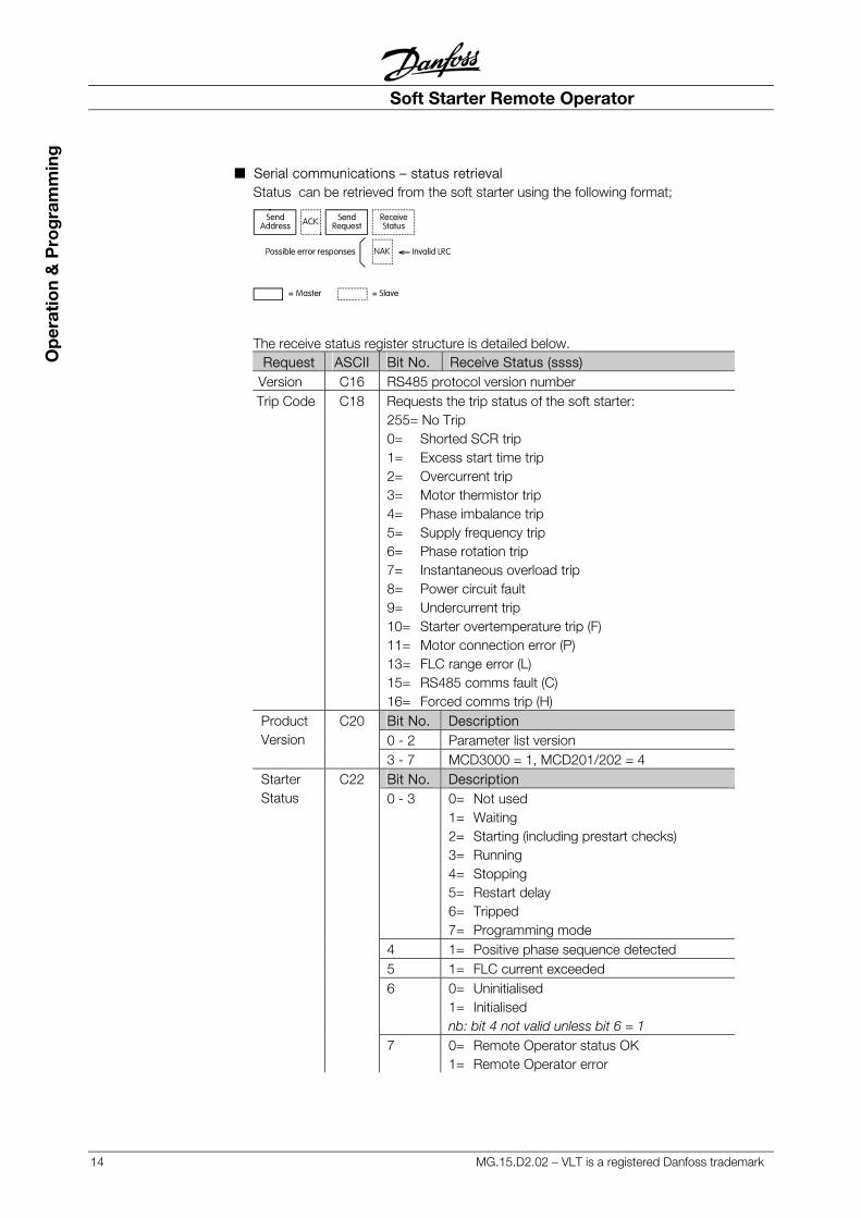
g ■ Serial communications – status retrieval
Status can be retrieved from the soft starter using the following format;
SendAddress ACK Send
Request
NAK
ReceiveStatus
Invalid LRCPossible error responses
= Master = Slave
The receive status register structure is detailed below. Request ASCII Bit No. Receive Status (ssss)
Version C16 RS485 protocol version number Trip Code C18 Requests the trip status of the soft starter:
255= No Trip 0= Shorted SCR trip 1= Excess start time trip 2= Overcurrent trip 3= Motor thermistor trip 4= Phase imbalance trip 5= Supply frequency trip 6= Phase rotation trip 7= Instantaneous overload trip 8= Power circuit fault 9= Undercurrent trip 10= Starter overtemperature trip (F) 11= Motor connection error (P) 13= FLC range error (L) 15= RS485 comms fault (C) 16= Forced comms trip (H) Bit No. Description 0 - 2 Parameter list version
Product Version
C20
3 - 7 MCD3000 = 1, MCD201/202 = 4 Bit No. Description 0 - 3 0= Not used
1= Waiting 2= Starting (including prestart checks) 3= Running 4= Stopping 5= Restart delay 6= Tripped 7= Programming mode
4 1= Positive phase sequence detected 5 1= FLC current exceeded 6 0= Uninitialised
1= Initialised nb: bit 4 not valid unless bit 6 = 1
Starter Status
C22
7 0= Remote Operator status OK 1= Remote Operator error
Soft Starter Remote Operator
MG.15.D2.02 – VLT is a registered Danfoss trademark 15
Ad
vanced S
et Up
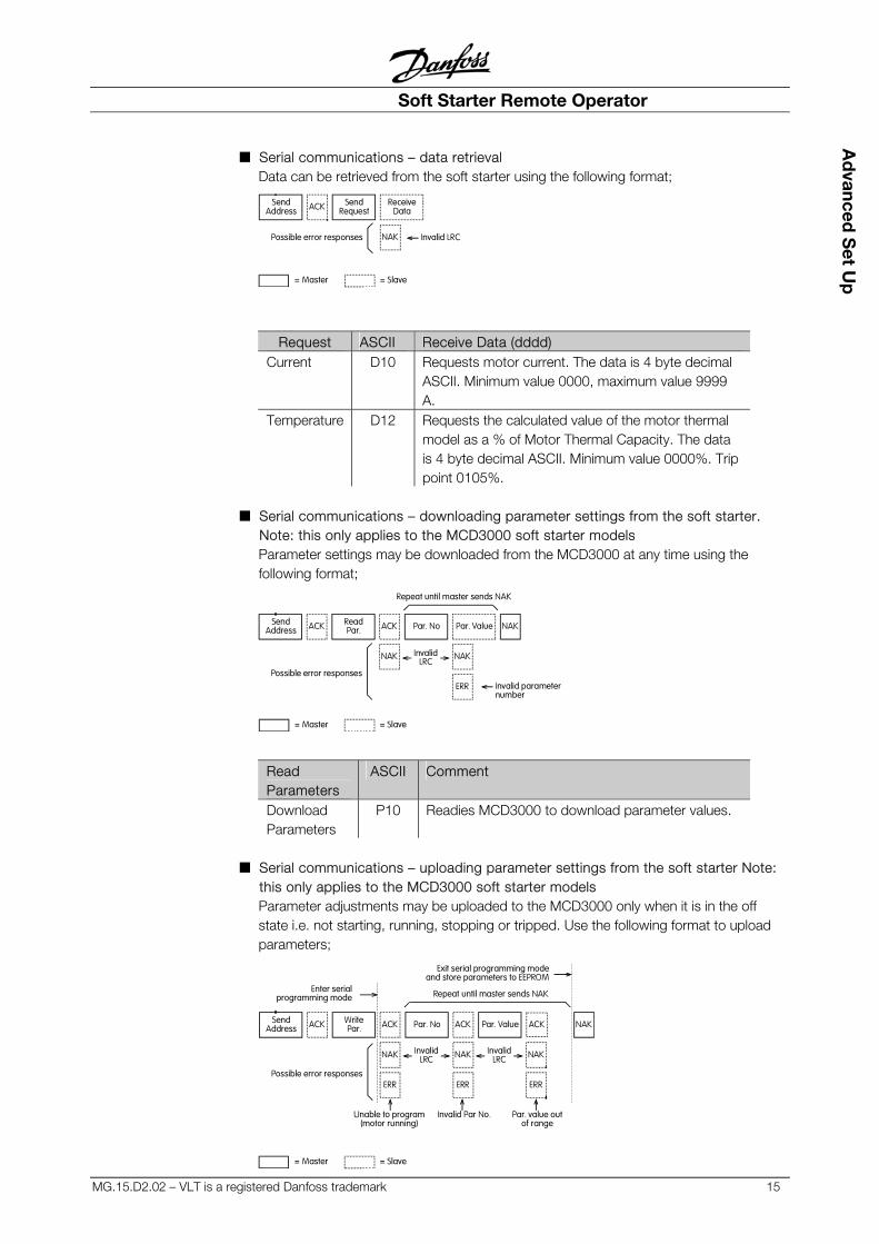
■ Serial communications – data retrieval Data can be retrieved from the soft starter using the following format;
SendAddress ACK Send
Request
NAK
ReceiveData
Invalid LRCPossible error responses
= Master = Slave
Request ASCII Receive Data (dddd) Current D10 Requests motor current. The data is 4 byte decimal
ASCII. Minimum value 0000, maximum value 9999 A.
Temperature D12 Requests the calculated value of the motor thermal model as a % of Motor Thermal Capacity. The data is 4 byte decimal ASCII. Minimum value 0000%. Trip point 0105%.
■ Serial communications – downloading parameter settings from the soft starter.
Note: this only applies to the MCD3000 soft starter models Parameter settings may be downloaded from the MCD3000 at any time using the following format;
SendAddress ACK Read
Par.
NAK
ACK Par. No Par. Value NAK
NAK
ERR
InvalidLRC
Possible error responsesInvalid parameternumber
Repeat until master sends NAK
= Master = Slave
Read Parameters
ASCII Comment
Download Parameters
P10 Readies MCD3000 to download parameter values.
■ Serial communications – uploading parameter settings from the soft starter Note:
this only applies to the MCD3000 soft starter models Parameter adjustments may be uploaded to the MCD3000 only when it is in the off state i.e. not starting, running, stopping or tripped. Use the following format to upload parameters;
SendAddress ACK Write
Par. ACK Par. No ACK NAK
NAK
ERR
ACK Par. Value
NAK
ERR
NAK
ERRPossible error responses
InvalidLRC
InvalidLRC
Unable to program(motor running)
Invalid Par No. Par. value outof range
Repeat until master sends NAK
Exit serial programming modeand store parameters to EEPROM
Enter serialprogramming mode
= Master = Slave
Soft Starter Remote Operator
16 MG.15.D2.02 – VLT is a registered Danfoss trademark
Op
erat
ion
& P
rog
ram
min
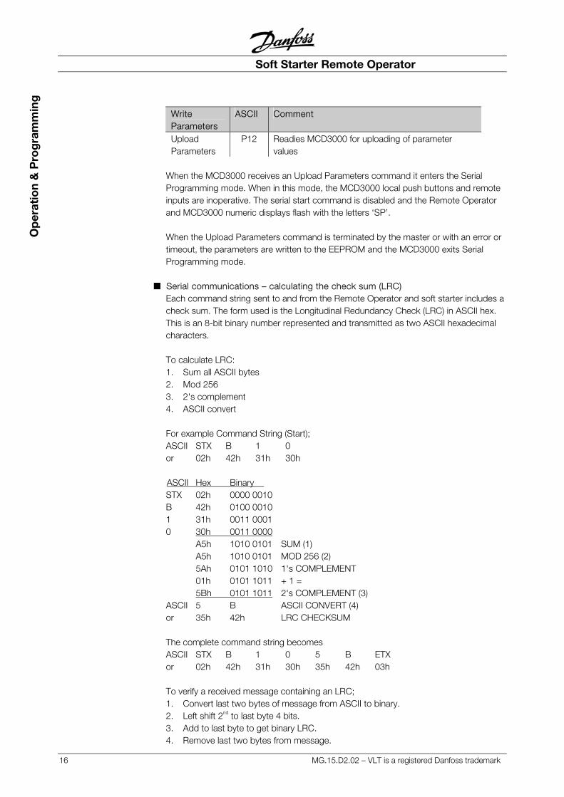
g Write Parameters
ASCII Comment
Upload Parameters
P12 Readies MCD3000 for uploading of parameter values
When the MCD3000 receives an Upload Parameters command it enters the Serial Programming mode. When in this mode, the MCD3000 local push buttons and remote inputs are inoperative. The serial start command is disabled and the Remote Operator and MCD3000 numeric displays flash with the letters ‘SP’. When the Upload Parameters command is terminated by the master or with an error or timeout, the parameters are written to the EEPROM and the MCD3000 exits Serial Programming mode.
■ Serial communications – calculating the check sum (LRC) Each command string sent to and from the Remote Operator and soft starter includes a check sum. The form used is the Longitudinal Redundancy Check (LRC) in ASCII hex. This is an 8-bit binary number represented and transmitted as two ASCII hexadecimal characters. To calculate LRC: 1. Sum all ASCII bytes 2. Mod 256 3. 2's complement 4. ASCII convert For example Command String (Start); ASCII STX B 1 0 or 02h 42h 31h 30h ASCII Hex Binary STX 02h 0000 0010 B 42h 0100 0010 1 31h 0011 0001 0 30h 0011 0000 A5h 1010 0101 SUM (1) A5h 1010 0101 MOD 256 (2) 5Ah 0101 1010 1's COMPLEMENT 01h 0101 1011 + 1 = 5Bh 0101 1011 2's COMPLEMENT (3) ASCII 5 B ASCII CONVERT (4) or 35h 42h LRC CHECKSUM The complete command string becomes ASCII STX B 1 0 5 B ETX or 02h 42h 31h 30h 35h 42h 03h To verify a received message containing an LRC; 1. Convert last two bytes of message from ASCII to binary. 2. Left shift 2nd to last byte 4 bits. 3. Add to last byte to get binary LRC. 4. Remove last two bytes from message.
Soft Starter Remote Operator
MG.15.D2.02 – VLT is a registered Danfoss trademark 17
Ad
vanced S
et Up
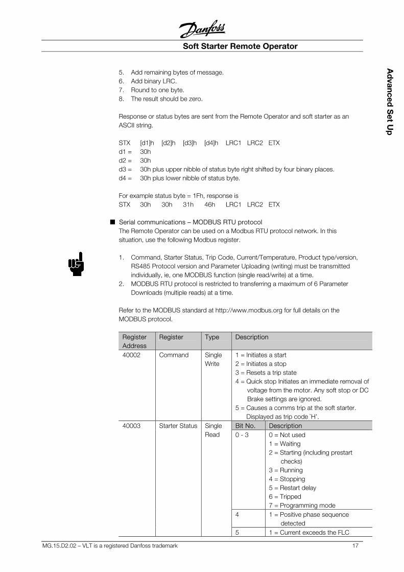
5. Add remaining bytes of message. 6. Add binary LRC. 7. Round to one byte. 8. The result should be zero. Response or status bytes are sent from the Remote Operator and soft starter as an ASCII string. STX [d1]h [d2]h [d3]h [d4]h LRC1 LRC2 ETX d1 = 30h d2 = 30h d3 = 30h plus upper nibble of status byte right shifted by four binary places. d4 = 30h plus lower nibble of status byte. For example status byte = 1Fh, response is STX 30h 30h 31h 46h LRC1 LRC2 ETX
■ Serial communications – MODBUS RTU protocol The Remote Operator can be used on a Modbus RTU protocol network. In this situation, use the following Modbus register. 1. Command, Starter Status, Trip Code, Current/Temperature, Product type/version,
RS485 Protocol version and Parameter Uploading (writing) must be transmitted individually, ie, one MODBUS function (single read/write) at a time.
2. MODBUS RTU protocol is restricted to transferring a maximum of 6 Parameter Downloads (multiple reads) at a time.
Refer to the MODBUS standard at http://www.modbus.org for full details on the MODBUS protocol.
Register Address
Register Type Description
40002 Command Single Write
1 = Initiates a start 2 = Initiates a stop 3 = Resets a trip state 4 = Quick stop Initiates an immediate removal of voltage from the motor. Any soft stop or DC Brake settings are ignored. 5 = Causes a comms trip at the soft starter. Displayed as trip code `H’. Bit No. Description 0 - 3 0 = Not used
1 = Waiting 2 = Starting (including prestart checks) 3 = Running 4 = Stopping 5 = Restart delay 6 = Tripped 7 = Programming mode
4 1 = Positive phase sequence detected
40003 Starter Status Single Read
5 1 = Current exceeds the FLC
Soft Starter Remote Operator
18 MG.15.D2.02 – VLT is a registered Danfoss trademark
Op
erat
ion
& P
rog
ram
min
g Register Address
Register Type Description
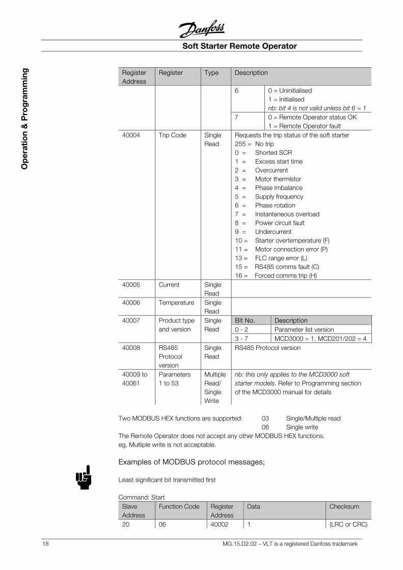
6 0 = Uninitialised 1 = Initialised nb: bit 4 is not valid unless bit 6 = 1
7 0 = Remote Operator status OK 1 = Remote Operator fault
40004 Trip Code Single Read
Requests the trip status of the soft starter 255 = No trip 0 = Shorted SCR 1 = Excess start time 2 = Overcurrent 3 = Motor thermistor 4 = Phase imbalance 5 = Supply frequency 6 = Phase rotation 7 = Instantaneous overload 8 = Power circuit fault 9 = Undercurrent 10 = Starter overtemperature (F) 11 = Motor connection error (P) 13 = FLC range error (L) 15 = RS485 comms fault (C) 16 = Forced comms trip (H)
40005 Current Single Read
40006 Temperature Single Read
Bit No. Description 0 - 2 Parameter list version
40007 Product type and version
Single Read
3 - 7 MCD3000 = 1, MCD201/202 = 4 40008 RS485
Protocol version
Single Read
RS485 Protocol version
40009 to 40061
Parameters 1 to 53
MultipleRead/ Single Write
nb: this only applies to the MCD3000 soft starter models. Refer to Programming section of the MCD3000 manual for details
Two MODBUS HEX functions are supported: 03 Single/Multiple read 06 Single write The Remote Operator does not accept any other MODBUS HEX functions. eg, Multiple write is not acceptable. Examples of MODBUS protocol messages; Least significant bit transmitted first Command: Start
Slave Address
Function Code Register Address
Data Checksum
20 06 40002 1 (LRC or CRC)
Soft Starter Remote Operator
MG.15.D2.02 – VLT is a registered Danfoss trademark 19
Ad
vanced S
et Up
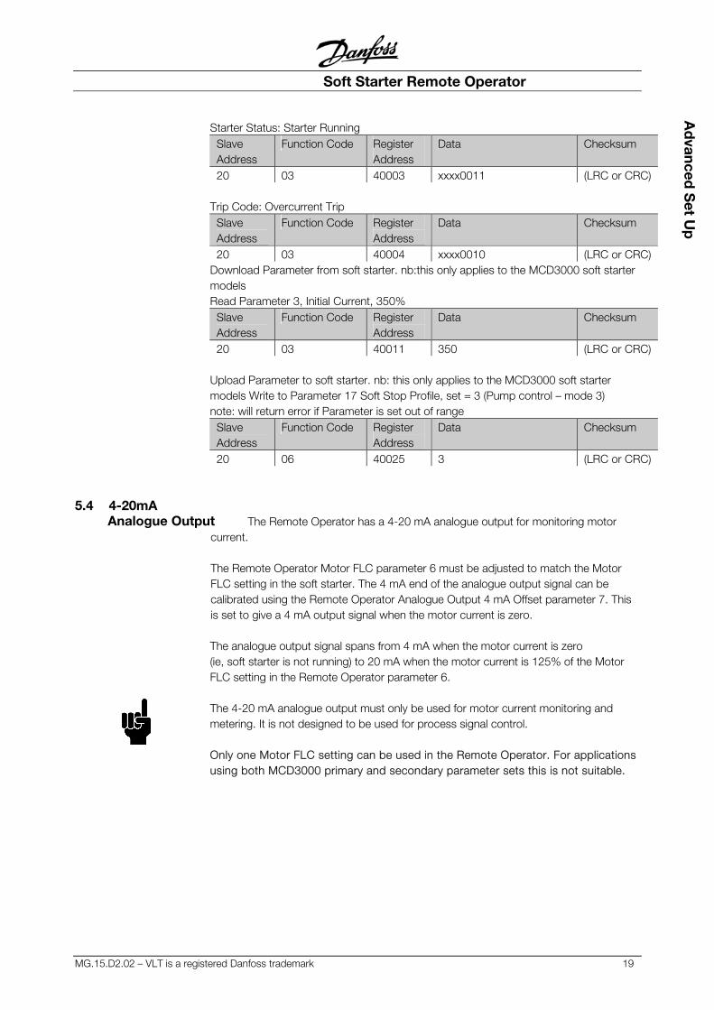
Starter Status: Starter Running Slave Address
Function Code Register Address
Data Checksum
20 03 40003 xxxx0011 (LRC or CRC) Trip Code: Overcurrent Trip
Slave Address
Function Code Register Address
Data Checksum
20 03 40004 xxxx0010 (LRC or CRC) Download Parameter from soft starter. nb:this only applies to the MCD3000 soft starter models Read Parameter 3, Initial Current, 350%
Slave Address
Function Code Register Address
Data Checksum
20 03 40011 350 (LRC or CRC) Upload Parameter to soft starter. nb: this only applies to the MCD3000 soft starter models Write to Parameter 17 Soft Stop Profile, set = 3 (Pump control – mode 3) note: will return error if Parameter is set out of range
Slave Address
Function Code Register Address
Data Checksum
20 06 40025 3 (LRC or CRC)
5.4 4-20mA Analogue Output The Remote Operator has a 4-20 mA analogue output for monitoring motor
current. The Remote Operator Motor FLC parameter 6 must be adjusted to match the Motor FLC setting in the soft starter. The 4 mA end of the analogue output signal can be calibrated using the Remote Operator Analogue Output 4 mA Offset parameter 7. This is set to give a 4 mA output signal when the motor current is zero. The analogue output signal spans from 4 mA when the motor current is zero (ie, soft starter is not running) to 20 mA when the motor current is 125% of the Motor FLC setting in the Remote Operator parameter 6. The 4-20 mA analogue output must only be used for motor current monitoring and metering. It is not designed to be used for process signal control. Only one Motor FLC setting can be used in the Remote Operator. For applications using both MCD3000 primary and secondary parameter sets this is not suitable.
MCD Remote Operator
20 MG.15.D2.02 – VLT is a registered Danfoss trademark
Tro
uble
Sho
oti
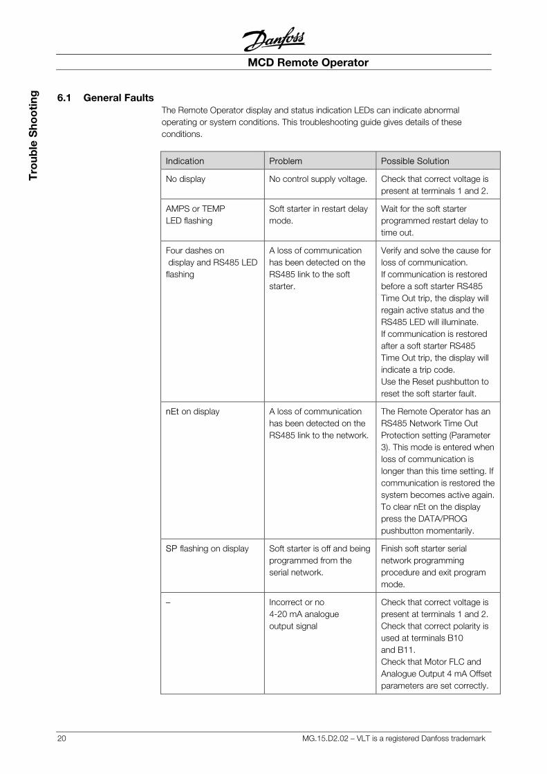
ng 6.1 General Faults The Remote Operator display and status indication LEDs can indicate abnormal
operating or system conditions. This troubleshooting guide gives details of these conditions.
Indication Problem Possible Solution
No display No control supply voltage. Check that correct voltage is present at terminals 1 and 2.
AMPS or TEMP LED flashing
Soft starter in restart delay mode.
Wait for the soft starter programmed restart delay to time out.
Four dashes on display and RS485 LED flashing
A loss of communication has been detected on the RS485 link to the soft starter.
Verify and solve the cause for loss of communication. If communication is restored before a soft starter RS485 Time Out trip, the display will regain active status and the RS485 LED will illuminate. If communication is restored after a soft starter RS485 Time Out trip, the display will indicate a trip code. Use the Reset pushbutton to reset the soft starter fault.
nEt on display A loss of communication has been detected on the RS485 link to the network.
The Remote Operator has an RS485 Network Time Out Protection setting (Parameter 3). This mode is entered when loss of communication is longer than this time setting. If communication is restored the system becomes active again.To clear nEt on the display press the DATA/PROG pushbutton momentarily.
SP flashing on display Soft starter is off and being programmed from the serial network.
Finish soft starter serial network programming procedure and exit program mode.
– Incorrect or no 4-20 mA analogue output signal
Check that correct voltage is present at terminals 1 and 2. Check that correct polarity is used at terminals B10 and B11. Check that Motor FLC and Analogue Output 4 mA Offset parameters are set correctly.
Soft Starter Remote Operator
MG.15.D2.02 – VLT is a registered Danfoss trademark 21
Tro
uble S
hoo
ting
6.2 Trip Codes When the soft starter trips the relevant trip code is displayed on the Remote Operator display. The CODE and TRIP LEDs are illuminated.
If the MCD3000 soft starter has an internal problem indicated by a Code E (EEPROM read/write failure), no communication is active between the soft starter and the Remote Operator. The Remote Operator display will indicate four dashes and its RS485 LED will flash. Refer to the Trip Codes section of the MCD3000 Operating Instructions and MCD201/202 Users Manual for details. This does not apply to the MCD201 open loop soft starter model.
Drives Solutions
www.danfoss.com/drives
Operating Instructions
MCD Remote Operator
Soft StarterSoft Starter
Operating Instructions
175R0964 MG15D202
XREF__BCNOT LOADED ON RIP
*MG15D202*REV. 2003-07-21