Embed Size (px)
Citation preview
mCAPACITORS IN AF CIRCUITS
by H. Baggott
It is weil know that coupling capacitors in hi-f audio circuits canadversely affect the tone quality of the circuits. Unfortunately, thereare frequently good reasons that make their use unavoidable. Buthow do you decide which type to use in a high-quality amplifier?
There are so many different types and makes on the marketthat this is not an easy decision. This article is intended to help in
choosing a suitable capacitor.
CONVENTlONAL eapaeitors are madeof two thin metal foils separated by a
thin insulator or dielectric, such as mica or aman-made fibre. This sandwich is rolled orfolded into a cornpact size and covered withan insulating coating. A wire terminal is at-tached to each foiI. Ta increase the capaci-tanee, the dieleetrie should be as thin as pos-sible. This ean only be done at the expenseof limiting the maximum voltage that canbe applied before the insulator ruptures be-cause of the intenseelectricfield. Another im-portant factar is the resistivity of the dielec-trie. Thin, large-area shapes increase theleakage resistance between the foils and thusdegrade the capacitor.
In ceramic and plastic-filrn capacitors,the metal-film plates are deposited direetlyon to the dielectric. Plastic dielectrics havevery high resistiviry so that the leakage re-sistance is very smalI.
Electrolytic capacitors are made of anoxidized meta! foil in a conducting paste(dry) or solution (wet). The thin oxide filmis the dieleetrie between the meta I foil andthe paste or solution. Since the film is verythin, the capacitance is large. The meta} foilis normally made of aluminium or tantal um.
The capacitance, C, of a capacitor is de-tennined by the dimensions of the foils andthe thiekness and relative permittivity, E,. ofthe insulator:
C=E,Aldx 8.85 x 10⁻¹² [farad],
where A is the surface area oftbe foils in m2
and d is the distance between the foils in m.The E, of polyester is about 3, while that oftantalum oxide is around 11.
The thiekness and type of material of thedielectric determine the breakdown voltageoftheeapaeitor: therefore, ahigh-voltage typeis larger than a low-voltage one.
A capacitor is a non-linear eJectrical corn-ponent, which rnakes it very useful in a num-ber of applications. Its specific characteris-tie is the frequency-dependent reactance,Xc, which, for an ideal capacitor, is
Xc= 112nfC [Q].
:'Q':~ .
•m:stantly dropping curve (on a logarithmicscale). This is, of course, not so, because thereactance would then really beeome 0 Q.
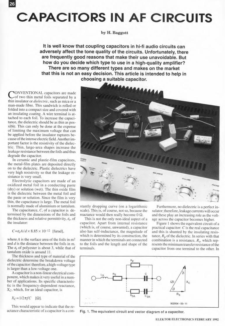
This is not the only non-ideal aspeet of acapacitor. Apart from interna! resistance(which is, of course, unwanted), a capacitoralso has self-inductance, the magnitude ofwhich is determined by its construction, themanner in which the terminals are connectedto the foils and the length and shape of tbetenninals.
Furtherrnore, no dielectric is a perfect in-sulator; therefore, Ieakage currents will occurand these play an increasing role as the volt-age across the eapacitor becomes higher.
Figure 1 shows the equivalent circuit of apractical capacitor: Cis the real capacitanceand this is shunted by the insulating resis-tance, Rp of the dieleetrie. In series with thatcornbination is a resistance, Rs• which rep-resents the miniraum transferresistanceofthecapacitor from one terminal to the other. In
e
IZI Xc,,, ,L_CJ--I._J
ROA GOA
e
902004 • 05- 11This would appear to indieate that the re-
actance characteristic of a capacitor is a con- Fig. 1. The equivalent circuit and vector diagram of a capacitor.
ELEKTOR ELECTRONICS FEBRUARY 1992
series with that network is the self-inductance,L" of the eapaeitor. Furthermore, in parallelwith C and Rp is aseries network consistingof ROA and COA, whieh represents the di-electric absorption of the capacitor. This is aless we!l-known property of eapaeitors. Thedielectric absorption, DA, is a charge dis-placement phenomenon in the dielectric thateauses a sort of memory lapse(adelayed trans-fer of acquired energy). Very few manufae-turers quote the DA in their datasheets. Thisphenomenon, which affeets the sound qual-ity of the circuit inwhich the capacitor is used,will be reverted to later on in the article.
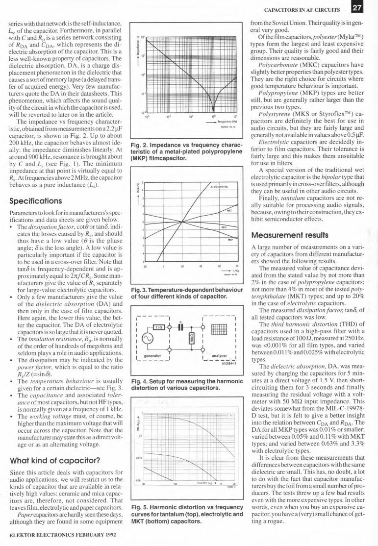
The irnpedance vs frequency character-istic, obtained from measurernents on a 2.2 ~capacitor, is shown in Fig. 2. Up to about200 kHz, the eapaeitor behaves a!most ide-a!ly: the impedanee diminishes Iinearly. Ataround 900 kHz, resonanee is brought aboutby C and Ls (see Fig. I). The minimumimpedance at that point is virtually equal toRs. At frequencies above 2 MHz, the capacitorbehaves as a pure inductance CLs).
SpecificationsParameters to look for in manufacturers's spec-ifications and data sheets are given below.
The dissipation facsor, cot8or tano, indi-eates the losses eaused by Rs, and shouldthus have a low value ce is the phaseangle; 8 is the loss angle). A low value isparticularly important if the capacitor isto be used in a eross-over filter. Note thattan8 is frequeney-dependent and is ap-proximately equal to 2rrfC Rs. Some man-ufacturers give the value of Rs separatelyfor large-value electroJytic capacitors.Onlya few manufacturers give the valueof the dielectric absorption (DA) andthen only in the case of film capacitors.Here again, the lower this value, the bet-ter the eapaeitor. The DA of eleetrolytiecapacitors is so large that it is neverquoted.The insulation resislance, Rp, is normaLlyof the order of hundreds of megohms andseidom plays a role in audio applieations.The dissipation may be indicated by thepower factor, which is equal to the ratioRs/Z (=sin 8).The temperature behaviour is usuallygiven for a certain dielectric-see Fig. 3.The capacitance and associated toter-ance of most capacitors.but not HF types,is normally given at a frequeney of 1kHz.The working voltage must, of course, behigher than the rnaximum voltage that willoccur across the capacitor. Note that themanu facturer may state this as a direct volt-age or as an altemating voltage.
What kind of capacitor?Since this article deals with capacitors foraudio applications, we will restriet us to thekinds of capacitor that are available in rela-tively high vaJues: ceramic and mica capac-itors are, therefore, not considered. Thatleaves film, eleetrolytie and papereapaeitors.
Papercapacitors arehardly seen thesedays,although they are found in some equipment
ELEKTOR ELECTRONICS FEBRUARY 1992
Ig6 10'_r .....U""~J{til)
,.0
Fig. 2. Impedanee vs frequeney eharae-terislie 01 a metal-plated polypropylene(MKP) lilmeapaeitor.
.' 71t.1,"'<1rol),lt~.1 ' /,
/ ::.::::<., -- 1/ »>-e.>/ --...:::., "" -/' / I----...z -; ,~,
.,/.,
• • • .. • •-'('Cl_ .... '"
Fig. 3.Temperature-dependent behaviour01lour different kinds 01eapaeitor.
I
11I111L ~e~,~Of__
------,.:1II1
1__ an~ly..:.e~_I9,Q084.11
Fig. 4. Setup lor measuring the harmoniedistortion of various capacitors.
,'0t
f '. ,.
",
- I "--,1o.c,~ ,
I,m,~ I I~ ,. '..........(HI)- ,. •'-'"
Fig. 5. Harmonie distortion vs Irequeneyeurves lor tantalum (top), eleetrolytie andMKT (bottom) eapaeitors.
CAPACITORS IN AF CIRCtJ1TS
fromtheSoviet Union. Theirquality is in gen-eral very good.
Of the fiImeapaeitors, polyester (Mylar™)types form the largest and least expensi vegroup. Their quality is fairly good and theirdimensions are reasonable.
Polycarbonate (MKC) eapaeitors haveslightly betterproperties than polyestertypes.They are the right choice for circuits wheregood temperature behaviour is important.
Polypropylene (MKP) types are betterstill, but are generaUy rather larger than theprevious two types.
Polystyrene (MKS or Styroflext'") ea-pacitors are definitely the best for use inaudio eireuits, but they are fairly large andgenerally notavailable in values aboveO.5 iJF.
Electrolytic capacitors are decidedly in-ferior to film capacitors. Their tolerance isfairly large and this makes them unsuitablefor use in filters.
A special version of the traditional weteleetrolytie eapaeitor is the bipolar type thatis used primarily incross-over filters, althoughthey can be useful in other audio circuits.
Finally, tantaluni capacitors are not re-ally suitable for proeessing audio signals,because, owing to theirconstruction, they ex-hibit semiconductor effects .
Measurement resultsA large number of measurements on a vari-ety of capacitors from different manufacrur-ers showed the foUowing results .
The measured value of capacitance devi-ated from the stated value by not more than2% in the case of polypropylene capacitors;not more than 4% in most of the tested poly-terephthalate (MKT) types; and up to 20%in the case of eLectrolytic capacitors.
The measured dissipation factor; tano, ofall tested capacitors was low.
The third harmonic distortion (THD) ofcapacitors used in a high-pass filter with aload resistanee of I00 Q, measured at 250 Hz,was <0.00 I% for all film types, and variedbetween 0.011 %andO.025% witheleetrolytietypes.
The dielectric absorption. DA, was mea-sured by charging the capaeitors for 5 min-utes at a direet voltage of 1.5 V, then short-eireuiting them for 3 seeonds and finallymeasuring the residual voltage with a volt-meter with 50 MQ input impedanee. Thisdeviates somewhat from the MlL-C-19978-D test, but it is feit to give a better insightinto the relation between COA and ROA' TheDA for aUMKP types was 0.01 % or smaUer;varied between 0.05%andO.11 % with MKTtypes; and varied between 0.63% and 3.3%with electrolytic types.
It is clear from these measurements thatdifferences between capacitors with the samedieleetrie are smalI. This has, no doubt, a lotto do with the fact that eapaeitor manufae-turers buytbefoil fromasmall numberofpro-dueers. The tests threw up a few bad resultseven with the more expensive types. In otherwords, even when you buy an expensive ca-pacitor, you have a (very) smaU chance of get-ting a rogue.
m AUDIO & Ill·FI
The poor DA figures of electrolytic ca-pacitors are probably the reason that thesecomponents often adversely affect the soundquality of audio circuits, which is not at allevident from their THD figures. Note thatthe DA and the THD have no direct rela-tionship.
The self-inductance ofthe capaci tors testedwas negligibly small: <50 nH in the case of2.2 ~ capacitors. Modern production meth-ods appear to resuJt in minimal self-induc-tance: most of this is formed by the termi-nals (Iength and shape).
As an aside: when procuring the manycapacitors for the tests, it was found that thelarger values are normally stocked by loud-
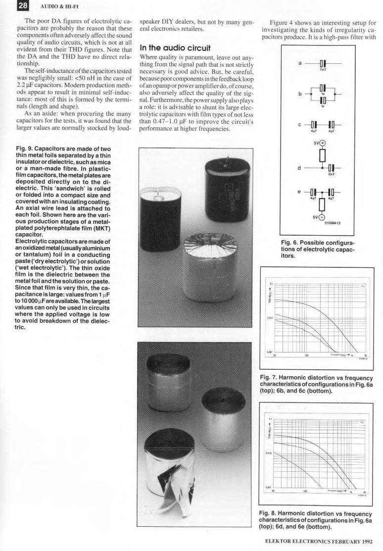
Fig. 9. Capaeitors are made 01 twothin metal loils separated by a thininsulatoror dielectric, such as micaor a man-made libre. In plastlc-lilm eapaeitors, the metal plates aredeposited direetly on to the dl-eleetrie. This 'sandwich' is rolledor lolded into a eompaet size andcovered with an insulating coating.An axial wire lead ls attaehed toeaeh loil. Shown here are the vari-ous produetion stages 01 a metal-plated polyterephtalate lilm (MKT)capacitor.Eleetrolytie eapaeitors are made 01anoxidized metal (usually aluminiumor tantalum) loi! in a eonduetingpaste ('dry eleetrolytie') or solution('wet eleetrolytie'). The thin oxidefilm is the dieleetrie between themetal loil and the solution or paste.Sinee that film is very thin, the ca-paeitanee is large: values Irom 1~Fto 10 000~Fareavailable.The largestvalues can only be used in circuitswhere the applied volta ge ls lowto avoid breakdown 01 the dielee-tric.
speaker D1Y dealers, but not by many gen-eral electronics retailers.
In the audio circuitWhere quality is pararnount, leave out any-thing from the signal path that is not strictlynecessary is good advice. Bur, be careful,because poorcomponents in the feedback loopof an opamp orpower amplifierdo, of course,also adversely affect the quality of the sig-nal. Furthermore, the power supply also playsa role: it is advisable to shunt its large elec-trolytic capaeitors with film types of not lessthan 0.47-1.0 ~ to improve the eircuil'sperformance at higher frequencies.
Figure 4 shows an interesting setup forinvestigating the kinds of irregularity ca-pacitors produee. It is a high-pass filter with
a --Ill----,,,
b-db-"
c -(] t---Ill--
e -1JJ;r,-tq-5V~
910084-13
Fig. 6. Possible eonligura-tions 01 eleetrolytie capac-itors.
.., A,tf~
IlD,G c--. J I"-.....
'. -,I~,1II "~,
"~I""""'(lI.I)-'k• ,. a.'-"Fig. 7. Harmonie distortion vs Irequeneycharacteristics of configurations in Fig. 6a(top); 6b, and 6e (bottom).
"t
A,
fi
••• f':"-, 1"-
-, ,".m' • ,. '''''''''''(111)- .. •,,-~
Fig. 8. Harmonie distortion vs Irequeneycharacteristics of configurations in Fig. 6a(top); 6d, and 6e (bottom).
ELEKTOR ELECTRONICS FEßRUARY 1992
cut-off frequency at around 400 Hz. A rela-tively low load is used to better show up anydeficiencies (high Ioads improve the distor-tion factor). A frequency of a few hundredhertz is necessary to show how the capaci-tor behaves below the cut-off point.
Figure 5 shows the harmonie distortionof three types of capacitor: MKT, wet elec-
t ' "f~ I I.,tlo,o I I
1,1101I m
~,10 ....... ,.'.., .....U , "_.
Fig. 1O.Distortion vs applied voltage char-aeteristie 01an eleetrolytie eapaeitor(top)and a metal-plated polypropylene type;the test Irequeney was 500 Hz.
s \0',i''''--,._-".,--
lo·,L_Ll.llllIIL.L.1illWL.LlllJ.lJlL....l..illlilll1~ w 1~ ~ ~
- fctquon<y(H,)
Fig. 11. Impedanee vs Irequeney eharae-teristie 01 an eleetroly1ie eapaeitor showsthat above 10kHz the eomponent doesno longer behave like a eapaeitor.
,,' LUJLlllJIIL.LL.1J.lD' 10' 10' lU'
_ frtt!u.n<y(H')__ .. ·n
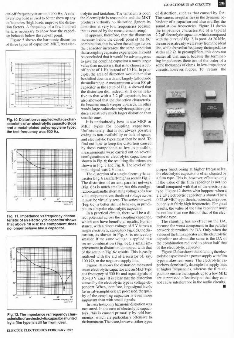
Fig. 12.The impedanee vs Irequeney char-acteristie01anelectroly1iecapaeitorshuntedby a lilm type is still lar Irom ideal.
ELEKTOR ELECTRONICS FEBRUARY 1992
trolytie and tantal um. The tantalum is poor,the electrolytic is reasonable and the MKTproduces virtually no distortion (ignore itsdistortion at very low frequencies becausethat is caused by the measurement setup).
lt appears, therefore, that the distortionincreases below the cut-off point of the Recornbination, that is, when the voltage acrossthe capacitor increases: the same conditionthata coupling capacitorexperiences. Itcouldbe eonc1uded that it would be advantageousto give the coupling capacitor a much largervalue tban necessary, that is, to eboose a cut-off point of I Hz instead of 10 Hz. In prin-eiple, tbe area of distortion would then alsobeshifted downwards and Iargely fall outsidethe audio range. A rneasurement with a 100 Ilfcapaeitor in the setup of Fig. 4 showed thatthe distortion did, indeed, shifr down rela-tive 10 that with a 2.2 Ilf capaeitor, but italso showed that the distortion characteris-tic beeame much steeper upwards. In otherwords, large-value electrolytic capacitors pro-duce a relatively mueh larger distortion thansmaJler ones.
It is undoubtedly best to use MKP orMKT types for coupling eapaeitors.Unfortunately, that is not always possibleowing to non-availability or lack of spaee,and eleetrolytie types must then be used. Tofind out how to keep the distortion eausedby these eomponents as Iow as possible,measurements were earried out on severaIconfigurations of electrolytic capacitors asshown in Fig. 6; the resulting distortions areshown in Fig. 7 and Fig. 8. The level of theinput signal was 2 V r.m.s,
The distortion of a single eleetrolytic ca-pacitor(Fig. 6 a) is fairly high as seen in Fig. 7.The distortion of an anti-parallel network(Fig. 6b) is much smaller, but this configu-ration can handle alternating voltages of a fewvolts onJy; moreover, the direct voltage acrossit must be virtually zero, The series network(Fig. 6e) is better still; it behaves, in princi-pIe, as abipolar eleetrolytie capacitor.
In a practical circuit, there will be a di-reet potential across the coupling capacitor,which ean have beneficial results. For in-stanee, with a direct voltage of 5 V aeross asingieelectrolyticeapacitor(Fig. öd), the dis-tortion, as shown in Fig. 8, is noticeablysmaller. U the same voltage is applied to aseries combination (Fig. 6e), a sm all im-provement in distortion compared with thatof the setup in Fig. 6e results. This is easilyrealized with the aid of a resistor of, say,100 W, to the negative supply line.
Figure 10 shows the distortion measuredon an electrolytic eapaeitor and an MKP typeat a frequency of 500 Hz and input signals of0.5-10 V r.m.s. lt is clear that the distortioncaused by the electrolytie type is voltage-de-pendent. When, therefore, large signal levels(as in valve arnplifiers) are processed, the qual-ity of the coupling capacitor is even moreimportant than with small signals.
In these tests, onJy harmonie distortion wasmeasured. In the ease of electrolytie capaci-tors, this is caused primarily by odd har-monies, whieh are particularly offensive tothe human ear. There are, however, other types
CAPACITORS IN AF CIRCUITS mof distortion, such as that eaused by DA.This eauses irregularities in tbe dynamic be-haviour of a capacitor and also muffies thesound at low frequencies. Figure 11 showstbe impedance characteristic of a typical2.2 Ilf eleetrol ytic capaei tor, which, comparedwith the eurve of Fig. 2, is poor. At 20 kHz,the eurve is a!ready weIl away frorn the idealline, while above that frequeney, the impedaneesticks at 2 rl. In prearnplifiers, this does notmatter all that much, because the terminat-ing impedances there are of the order of asorne thousands of ohms. In low-irnpedancecircuits, however, it does. To retain the
proper functioning at higher frequencies,the electrolytic capacitor is often shunted bya film type. This is, however, effeetive onlyif the value of the film capacitor is not taosmall eompared with that of the eleetrolytictype. Figure 12 shows what happens when a2.2 Ilf electrolytic capaeitor is shunted by a0.22 IlfMKT type: theeharaeteristic improvesbut only at fairly high frequencies. For goodresults, tbe value of the film capacitor mustbe not less than one third of that of the elec-trolytic type.
The shunting has no effeet on the DA,because the worst component in the parallelnetwork determines the DA. Only when thevalues ofthe film capacitor and the eleetrolytiecapacitor are about the same is the DA ofthe eombination redueed to about half thatof the electrolytie eapaeitor.
Figure 12also shows thatshunting the elec-trolyticcapacitors in a powersupply with filmtypes makes reaJ sense. The electrolytic ca-paeitorsalone hardly decouplethe supply linesat higher frequeneies, whereas the film ca-pacitors ensure that signals up to a few MHzare suppressed effectively so that they can-not cause interference in the audio circuits.•