Embed Size (px)
Citation preview

© COPYRIGHT 2009 Quadlogic Controls Corporation
MiniCloset-5c
Installation Manual

© COPYRIGHT 2009 Quadlogic Controls Corporation
Table of Contents
Contact Information................................................................................1Warning ................................................................................................1Disclaimer .............................................................................................1Symbols................................................................................................1
Chapter 1
IntroductionOverview...............................................................................................3Power Line Communications (PLC) ............................................................3Scan Transponder-5 (PLC Data Collector and Communicator)........................3Quadlogic Metering System......................................................................4
Chapter 2
About the MiniCloset-5cThe MiniCloset-5c ...................................................................................6Specifications.........................................................................................7
Chapter 3
Parts and Options Parts.....................................................................................................9Options .................................................................................................9
Chapter 4
InstallationOverview.............................................................................................13Installation Cautions and Warning...........................................................13Protective Conductor Terminal ................................................................13Installation Instructions for Meter, MCI, and CTs .......................................14Wiring Overview ...................................................................................183-Phase, 4-Wire Wye Wiring...................................................................181-Phase, 3-Wire 120/208V Wiring (Network) ............................................253-Phase, 3-Wire Delta Wiring .................................................................313-Phase, 4-Wire 1EL Wiring....................................................................371-Phase, 3-Wire 240V 1EL Wiring............................................................431-Phase, 3-Wire 240V 2EL Wiring............................................................49
Chapter 5
Using the MeterDisplay Navigation ................................................................................55Verifying Meter Functionality ..................................................................58Resetting Demand Values (For Commercial Applications only) .....................60
Chapter 6
Applying MultipliersReading the Display ..............................................................................61How CT multipliers are calculated............................................................62
© COPYRIGHT 2009 Quadlogic Controls Corporation
Chapter 7
CommunicationsOverview.............................................................................................63HyperTerminal Private Edition Setup........................................................63Security Hierarch..................................................................................65Logging In To the Meter ........................................................................65Basic Meter Data ..................................................................................66Advanced Meter Programming ................................................................69
Chapter 8
TroubleshootingResolving Meter Issues..........................................................................71
Chapter 9
Repair and Spare PartsRepair or Replacement ..........................................................................73Spare Parts..........................................................................................73
Chapter 10
MiscellaneousPreventive Maintenance.........................................................................75Warranty Information............................................................................75Release Dates ......................................................................................75Revision History ...................................................................................75
AppendixThe Communications Module ..................................................................76RS-485 Overview..................................................................................79Guidelines for Proper Wiring of a RS-485 Network .....................................79The Pulse Datalogger Module..................................................................85

© COPYRIGHT 2009 Quadlogic Controls Corporation
1
Thank you for purchasing a MiniCloset-5c multi-channel electric power meter manufactured byQuadlogic Controls Corporation. Quadlogic has been designing, manufacturing, and selling digitalelectric metering systems for over 25 years. We appreciate your business.
CONTACT INFORMATION
For sales and technical support, please contact Quadlogic Controls Corporation as indicatedbelow.
Quadlogic Controls Corporation
Telephone: (212) 930-9300
Fax: (212) 930-9394Email: [email protected]: www.quadlogic.com
WARNING
This manual is for persons who have received training and are qualified to work with
electricity and electrical metering equipment. All applicable national and local electricalcodes and standards must be followed. Failure to follow proper procedures may result indamage to the equipment and/or serious bodily harm including death.
DISCLAIMER
The information in this manual has been compiled with care, however, Quadlogic ControlsCorporation makes no warranty as to the accuracy or completeness of this material.Furthermore, the product(s) described herein may be changed or enhanced from time totime. This information does not constitute commitments or representations by QuadlogicControls Corporation, and is subject to change without notice.
SYMBOLS
WARNING
NOTE
CAUTION

© COPYRIGHT 2009 Quadlogic Controls Corporation
2

© COPYRIGHT 2009 Quadlogic Controls Corporation
3
CHAPTER 1
INTRODUCTION
OVERVIEW
Quadlogic Controls Corporation manufactures a line of revenue-grade electricity meters andmetering systems that utilize our patented, two-way Power Line Communicationstechnology. For over 25 years, Quadlogic systems have used this patented technology totransmit advanced meter data over the existing power lines in a building or service territory.No additional communication wiring is required to transmit metered data to the ScanTransponder (Quadlogic’s data collector). Because the system is read remotely via various
public or private communication means, meter readers are also not required. Building andfacility owners, property managers, and utility companies depend on Quadlogic meters toprovide all the data needed to bill customers, allocate energy costs, manage loads, andmake smart energy decisions.
POWER LINE COMMUNICATIONS (PLC)
Power Line Communications, or PLC, is a method of transferring meter data via the existingelectric power wires that serve each tenant in a building or customer on a utility grid.Quadlogic employs a patented method of PLC to move large amounts of metered data forresidential and commercial and industrial (C&I) customers to a central collection point. Thisrobust technology dynamically responds to the varying electrical noise conditions normallyfound on power lines or electrical distribution grids by changing frequency, phase etc. and is
therefore able to maintain highly reliable data communication, including passing throughdistribution transformers. (Consult Quadlogic or local representative for project layoutassistance.) The MiniCloset-5c includes PLC communications as a standard feature. In mostinstallations, the meter data from the MiniCloset-5c is read remotely via PLC.
SCAN TRANSPONDER-5 (PLC DATA COLLECTOR AND COMMUNICATOR)
When the MiniCloset-5c is read via PLC, one or more Scan Transponder-5’s are required. TheScan Transponder-5 is the central data collector for Quadlogic metering systems. Itcommunicates with Quadlogic meters over the existing electric wires that serve each tenantin a building or customer on a utility grid.
The Scan Transponder-5 collects a data block from each meter in the system. The blockcontains all previously uncollected meter readings, interval readings and event logs. Thisdata is stored in a non-volatile memory buffer. At regular intervals, the billing systemcommunicates with the Scan Transponder-5 and uploads all of the information for billing oranalysis purposes.
The Scan Transponder-5 is a separate product and requires its own installation.

Chapter 1 Introduction
© COPYRIGHT 2009 Quadlogic Controls Corporation
4
Figure 1-1. Quadlogic Scan Transponder-5.
QUADLOGIC METERING SYSTEM
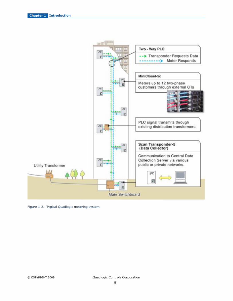
The MiniCloset-5c is typically part of a comprehensive metering system within residential,
commercial, industrial or mixed-use sites. (See Figure 1-2 for a typical Quadlogic PLCmetering system.) This metering system measures electrical usage for each tenant(customer), cost center, or common area space, and communicates this metering data overthe power distribution wires. A metering system is comprised of two or more Quadlogicelectricity meters and at least one Quadlogic Scan Transponder-5 (ST-5), which isQuadlogic’s data collector and concentrator. The ST-5 collects metering data for up to 240
metering points via the power lines. Large sites may require additional ST-5s. Multiple ST-5’s are typically interconnected via a data link network using RS-485 or via a wirelessnetwork.
Chapter 1 Introduction
© COPYRIGHT 2009 Quadlogic Controls Corporation
5
Figure 1-2. Typical Quadlogic metering system.

© COPYRIGHT 2009 Quadlogic Controls Corporation
6
CHAPTER 2
ABOUT THE MINICLOSET-5C
THE MINICLOSET-5C
The MiniCloset-5c, or MC-5c, is a multi-tenant digital electric meter used for commercial,
residential or industrial applications. It meters up to 24 circuits or channels, which can beconfigured as 24 single-phase/circuit loads, 12 two-phase/circuit loads, 8 three-phase/circuitloads, or any equivalent combination. It records interval data, including hourly and 15minute intervals, down to 5 minutes which allows flexible load profiling and Time-of-Use(TOU) billing options. It also measures four-quadrant energy, power-down events,frequency, etc. enabling the user to analyze power quality.
Figure 2-1. The MiniCloset-5c.
The MC-5c utilizes flash memory which enables reliable data storage and integrity withoutbattery reliance. In addition to metering data, it stores power quality data and acomprehensive list of relevant events. The recorded events include: power consumption,demand resets, power ups and power downs, time changes, and tampers. In addition toremote reading, the consumption readings, power quality and event data are also accessible
by reading the built-in Liquid Crystal Display (LCD) or using a computer and optical probe.(See chapter 5 for more information on the meter display.)
Using a Pulse Datalogger Module (PDM), the MC-5c is capable of collecting pulse data fromany device capable of a dry contact outputs, such as water, gas, or BTU meters. Each PDMcan count pulses for up to 12 discrete meters, and four PDMs can be daisy-chained together.
Therefore up to 48 different meters, (4x12) can be assigned to one MC-5c. Note; This datacan be recorded at different intervals than those set for the electricity readings.

Chapter 2 About the MiniCloset-5c
© COPYRIGHT 2009 Quadlogic Controls Corporation
7
SPECIFICATIONS
Metering Specifications
Metered Voltage:
Secondary Current Input:Programmable:Four Quadrant Consumption &
Delivered and received
Demand for each of the 24 channels:
Programmable Interval Data &Data and Peak Demand:
Demand Reset:Real-time data per Phase:
Time-of-Use:
Data Collection Options:
Pulse Datalogger Module (PDM-12):
Distance:
Interrogating Signal Specifications:
120, 208, 220, 230, 240, 277, 347, 380, 400, 416, 480,600 VACDelta or Wye, 50/60 Hz0.1 Amp or 5 Amp CT inputs available
(8) 3-phase meters, (12) network meters, or (24)single-phase meters (number of meter points available willvary by model)Delivered and received: kW, kVARLeading,kVARLagging, kVA, Volts-squared hours, and amp-squaredhours
5 minutes to hourly time window (longer time intervals alsoavailable)Meter total and/or by phaseProgrammable to user-determined specific time blocks orrolling time block demand Allows local reset of peak demand (kW) registerVoltage, current, phase angle, power factor, THD, watts,VARs, VA, and frequencyUp to 16 blocks per day available for all meteringparameters (Exception: Pulse input data)IQ SoftwareMV-90 TIM ModuleASCII-based, open-data protocolOpen-source data conversion programCollects data from up to 12 water, gas, or BTU metersForm A Dry Contact InputsPDM connects to MiniCloset-5c via CAT5Maximum 4 PDM units to a MC-5c (daisy chain)Total of 48 discrete inputs totalPulses will count during a power outagePulses can be logged in programmable intervalsPower supplied by MiniCloset-5cPulse meter to PDM - 300’ max.(18 gauge min.)All 4 PDM’s to MC-5c - 300’ CAT5 cableMin. Pulse Width:
Power on - 50 msec.Power off - 500 msec.*
Max. Pulse Rate:Power on - 10 pulses/sec maxPower off - 1 pulse/sec max
Peak voltage: 5.5VPeak current: not applicableIsolation: The interrogating signal is completely isolated from the AC line, with isolation barriers rated for at least 2.5 kV.Max. signal debounce tolerance: 20 msec.

Chapter 2 About the MiniCloset-5c
© COPYRIGHT 2009 Quadlogic Controls Corporation
8
The pulses that are counted by the PDM consist of a 'closed' state on the external contact,followed by an 'open' state. In order to be reliably registered, the time that the contact is'open' must be at least the Min Pulse Width, and the time that the contact is 'closed' must
also be at least the Min Pulse Width.* When the MC-5c loses power or is disconnected from the PDM, the PDM has the capabilityto record pulses using its onboard battery for power. In this situation, the sample rate of thePDM is reduced to decrease current drain and extend battery life.
Communications Options
Although a MiniCloset-5c is typically part of an AMR (Automatic Meter Reading) Systemwhereby metering data is collected by a Scan Transponder using PLC, in some cases a usermay need to communicate with the meter directly. In addition to the Power LineCommunications capability that is a standard feature of the MiniCloset-5c, the followingcommunications options are available:
• Local LCD (register values and certain diagnostic data are available via local LCD)• IEC Optical Communications Interface (optical port is standard feature; optical probe
is sold separately)• 19.2k Internal Modem/RS232/RS485 (Option)• Network Data Link (4-wire RS-485) (Option)
Accuracy:
Liquid Crystal Display:
Operating Range:
Memory:
Shipping Weight and Dimensions:
Environment:
Type Tests:
Metering Industry Standards:
±0.5% at unity power factor at any measured load between 1%and 100% of full-scale (excluding external CT error)±0.75% at 0.5 power factor (lead or lag)Push button scroll32-digit liquid crystal display (16 digits x 2 rows)6 whole digit consumption registerData digit height: 0.31”Programmable display scroll & decimal place displayRated Voltage: 90% to 110%Temperature: -20˚C to +60˚C512 Kbytes non-volatile flash memoryDuring power outage:
Flash memory retains daily and interval dataLong-life lithium battery maintains time, logs incomingpulses and retains data acquired within the uncompletedinterval at the time of the outage
Enclosure: 18.2" H X 10.70" W X 6.1” DShipping weight: 1 meter assembly: 34 lbsEnclosure: NEMA 1 rated for indoor use only.Temperature: -20˚C to +60˚CHumidity: 0-95% relative humidity (non-condensing)Pollution Degree: 2Maximum Altitude: 2000 metersTransient/surge suppression: ANSI C37.90.1-1989Installation Category: III. This product falls under InstallationCategory III because of its distribution level, fixed installation,and because it has a smaller transient over-voltage rating thanan Installation Category IV.Meets ANSI: C12.1UL and CUL: Recognized under E204142Industry Canada: MC# AE-1148

© COPYRIGHT 2009 Quadlogic Controls Corporation
9
CHAPTER 3
PARTS AND OPTIONS
PARTS
Figure 3-1. MiniCloset-5c, Parts and Assembly
A. Meter Head – Main component of the MiniCloset-5c. The Meter Head contains the MeterModule, through which all signals transmit, events are recorded and meter data is stored.
B. Voltage Connector – A 14-pin connector that connects the Fuse Block (C) and the MeterHead (A).
C. Fuse Block – Provides termination for the voltage taps. It supplies power and fuseprotection to the Meter Head.
D. MC-5c Back Box – Metal box housing the metering device and the MCI board.E. MCI – MiniCloset Interface, provides termination for the current transformers (CT).
F. Shorting Links – Provide termination for CTs when the Current Connectors aredisconnected from the meter head.
G. Communications Module (option).H. Front Door of MC-5c.I. Current Connectors – A 15-pin connector that connects the MCI and the Meter Head
together. Each MC-5c has 4 Current Connectors.
OPTIONS
The following options are available with the MC-5c. A suffix on the meterhead catalog number willindicate which option or options are included with that model as indicated below.
Options
Description Suffix for Meterhead Need to order separate part?
Modem Modem, RS-485, RS-232 M No. Modem/RS-232/RS-485 is included in "M" modelmeterhead.
RS-485 RS-485 only RS No. RS-485 is included in "RS" model meterhead.
PDM Pulse Data Module for Form Adry contact inputs
P Yes. "P" model meterheads do not include the PDMdevices. PDMs need to be ordered separately. (Up to 4
PDMs can be used on one MC-5c. 12 inputs x 4 PDMscollects 48 discrete inputs.)
Probe Abacus Electrics Optical Probeto download meter data locally
Not applicable Yes.

Chapter 3 Parts and Options
© COPYRIGHT 2009 Quadlogic Controls Corporation
10
I. Modem (Modem, RS-485, RS-232)
The Modem module is an optional accessory that can be ordered with the MC-5c. It includesa modem, RS-485 connection and RS-232 connection. The modem module connects to a
dedicated telephone line allowing remote data access directly to the device. Users candownload data or troubleshoot the system from any remote computer system.
II. RS-485
The Data Link External Communications or RS-485 module allows multiple Quadlogic metersto be connected together in cases where PLC is not being utilized. RS-485 utilizes two (2)
shielded, twisted pairs of #16 AWG stranded wires.
Figure 3-2. MiniCloset-5c with Modem and Data Link External Communications Module.
III. Pulse Datalogger Module
(See Appendix)
IV. Abacus Electrics Optical Probe
The Abacus Electrics optical probes (Model F6Z) are bi-directional interface devices utilizinginfra-red light. By connecting to the serial port of a computer or hand-held terminal, theypermit galvanically isolated communication with the MC-5c.
Figure 3-3. The Abacus Optical Probe.
Probes are available for use with laptop or desktop computers, as well as with many of thehand-held computers commonly used for field data collection. The probes are fitted with astandard 9-pin 'D' connector. The optical probe is convenient to use, as no battery or powersupply connection is needed.
ExternalCommunications Module

Chapter 3 Parts and Options
© COPYRIGHT 2009 Quadlogic Controls Corporation
11
V. Interface with Quadlogic Software (IQ)
The Interface with Quadlogic (IQ) Program allows for easy access to all metering information
necessary for basic bill generation, daily load profiling and certain customer service functionssuch as acquiring as needed reads for customers moving into or out of a designated location.Various metering parameters (Voltage, Amps, Watts, kWh, k VARh, kVAh, Power Factor andPhase Angle for one, two or three phases) can be viewed individually or in combination.Meters can be logically clustered, and the group totals for most metering parameters can beviewed as well.
Color graphs can be produced for Consumption and Daily Peak Demand, as well as DemandLogs. The program is both easy to use and provides professional presentation material.
IQ is available for purchase from Quadlogic Controls Corporation.
IQ requires the following minimum hardware and software:
Hardware:
486 or Pentium based PC 32 MB RAM minimum (64 MB RAM recommended) CD-ROM Drive
5 MB free space on the hard drive (for the program only) SVGA 800x600 Resolution Config.sys: files 50/buffers 15 minimum Color monitor Mouse Keyboard
At least 2400 baud or compatible modem (for remote connections only) Telephone line (for remote connections only) Printer (recommended)
Operating System Software:
• Windows 98, Windows NT, Windows XP
(Note: IQ is not compatible with Windows Vista)

Chapter 3 Parts and Options
© COPYRIGHT 2009 Quadlogic Controls Corporation
12
© COPYRIGHT 2009 Quadlogic Controls Corporation
13
CHAPTER 4
INSTALLATION
OVERVIEW
This chapter contains installation instructions and wiring diagrams for all MiniCloset-5c metermodels. The installation instructions start with a general procedure which applies to all metermodels, then continues with specific wiring and CT installation information for each particularMC-5c configuration. When installing the meter, it is critical that you use the correct wiringinstructions. See pages 18 to identify the correct instructions for your meter model.
INSTALLATION CAUTIONS AND WARNING
• This manual is for persons who have received training and are qualified to work withelectricity and electrical metering equipment. All applicable national and local electricalcodes and standards must be followed. Failure to follow proper procedures may result indamage to the equipment and/or serious bodily harm including death.
• Do not install if the device is damaged. Inspect the meter box for obvious defects such asdents or cracks in the housing.
• If the device is installed or used in a manner not specified by the accompanyingdocuments, the safety of the device may be impaired.
• If the device functions abnormally, proceed with caution. The safety of the device may beimpaired.
• Do not install the meter in the presence of explosive or combustible gas or gas vapor.• Do not install the meter on an electrical service with current or voltage outside of the
specified limits of the device.• Do not operate the meter with the cover removed.• To avoid electric shock, disconnect mains before replacing fuses.• Beware of working around this meter when the voltage is live. There is a risk of electric
shock.• To avoid electrical shock always install CT shorting links before removing meter head if
system is live.• For protection against fire, replace only with fuses of the specified voltage and current
rating.• See instructions for connection diagrams.
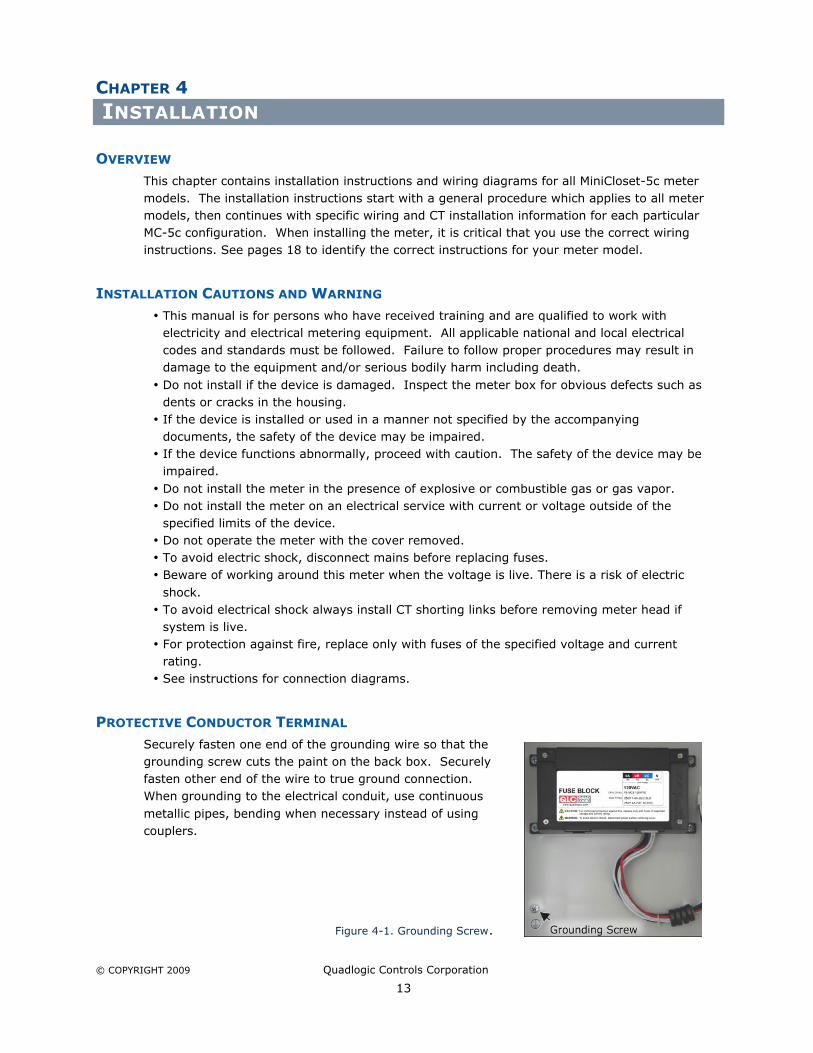
PROTECTIVE CONDUCTOR TERMINAL
Securely fasten one end of the grounding wire so that thegrounding screw cuts the paint on the back box. Securelyfasten other end of the wire to true ground connection.When grounding to the electrical conduit, use continuous
metallic pipes, bending when necessary instead of usingcouplers.
Figure 4-1. Grounding Screw.

Chapter 4 Installation
© COPYRIGHT 2009 Quadlogic Controls Corporation
14
INSTALLATION INSTRUCTIONS FOR METER, MCI, AND CTS
The use of the following procedure is mandatory both for safety and meter certification
purposes. Certification requires a visual inspection of the current transformers and thevoltage taps on the incoming feeder phase wires.
The MiniCloset-5c installation procedure consists of the following steps:1. Install metal box2. Optional communication module is installed, run communications wiring
3. Connect the meter’s voltage inputs to supply voltage4. Install Current Transformers (CT) in distribution panel and connect to the meter’s
current inputs5. Install meter head and optional communications unit, plug in to wiring harness
The installer needs to understand the following:
In order for the meter to be certified after installation, it must be possible to identify thephase to which each voltage tap and CT is connected. Therefore, it is a requirement that allwires be properly color-coded. Failure to color-code the wires will make it impossible tocertify the meter, and may require the entire installation to be re-done. In this document,we use the following color code:
Black – Phase A, or Line 1 for 240V installationsRed – Phase B, or Line 2 for 240V installations
Blue – Phase CWhite – Neutral (In wye installations only)
Local codes may require a different color code. If so, the installer must use the requiredcolor code consistently for each wire connecting the meter to the distribution panel.
Step 1: Install the back box and conduit
The MC-5c back box is the enclosure for the MCI and fuse block. The MC-5c back box issupplied with the fuse block pre-installed. If the optional communication module is ordered,it is pre-mounted to the MC-5c front cover. The MCI board contains the 48 screw terminalconnections for the current transformers. It is supplied with the MCI and current connector
wiring harness installed, with the CT shorting links in place.
1. Locate a section of wall to mount the meter. This should be as close as possible to thedistribution panel (preferably within 24”).
2. Mount the MC-5c back box to the wall. Connect the distribution panel box to the MC-5cback box with a metal conduit. This conduit will be used for the voltage taps. (Note: Theinstaller should use caution in creating punch outs other than those provided as this mayprevent the proper installation of the meter head). There will be between 2 and 4
#12AWG wires in this conduit, connected to the hot line(s) and neutral (if present). Theconduit should be sized to accommodate this. Also, a fused disconnect for the hot wiresmay be required. If so, the conduit should run through the fused disconnect.

Chapter 4 Installation
© COPYRIGHT 2009 Quadlogic Controls Corporation
15
3. Run a second metal conduit from the distribution panel box to the MC-5c back box. Thisconduit will be used for the CT secondary wires. In a 24-channel installation, there willbe 48 #16AWG wires. The conduit should be sized to accommodate this.
4. The metal box must be grounded. Either a ground wire may be run and attached to oneof the box mounting screws, or the box may be grounded by the conduit. Securelyfasten one end of the grounding wire so that the screw cuts the paint on the back box.Securely fasten the other end of the wire to true earth ground connection. Whengrounding to the electrical conduit, use continuous pipes, bending when necessary
instead of using couplers.
Step 2: Connect optional communications wiring
1. If using the optional communications module, you must arrange for the proper type ofcommunication line to be brought to the communications module box. This could be atelephone line, an RS-232 connection, or an RS-485 connection. This communicationline will connect to other equipment on-site. The details of this connection depend onthe particular installation.
2. Refer to detailed information for optional communication in the Appendix, page 76).
Step 3: Connect voltage taps
WARNING:
Power must be off when connecting these wires!
1. Locate the incoming feeder phase (hot) wires in the distribution panel. If color codedwiring is not being used, tape the incoming feeder wires with colored electrical tapeaccording to phase, for identification purposes.
2. Tap the feeder connections with #12 AWG stranded wires. These voltage connectionscan be made in any way that meets local codes and requirements. It is recommendedthat some means be provided to disconnect these voltage lines to facilitate servicing ofthe meter (fused disconnect, breaker, etc). Note: If fused, then no less than a 15A ‘FastActing’ fuses must be used. The color of the insulation on these wires must match the
color of the feeder connections to which they are attached. If neutral is required, tap theneutral connection with a #12 AWG stranded wire with white insulation.
3. Run the #12 AWG feeder phase tap wires through the conduit to the MC-5c back box.Connect the wires to the MiniCloset-5c Fuse Block.
Step 4: Install and connect Current Transformers (CTs)
WARNING:
Power must be off when connecting these wires!
Chapter 4 Installation
© COPYRIGHT 2009 Quadlogic Controls Corporation
16
DANGER:
Un-terminated CT secondary wires will produce hazardous electrical potentials if any currentis flowing through the CT. While connecting the CTs, POWER MUST BE OFF until the CTs
have all been connected to the MCI. Before power can be turned on, either the shortinglinks must be in place, or the 4 CT connectors must be plugged in to the meter head.Turning the power on with the meter unplugged and the shorting links removed will result ina condition that is hazardous to equipment and personnel.
This is the general procedure for connecting the current transformers. For specific wiring
instructions, refer to page 18 to identify the current instructions for your meter model.
1. Make sure shorting links are installed on the MCI.
2. Each CT is supplied with two secondary wires. One of these wires is colored either black,red, or blue, and the other wire is white. These 2 wires must pass through the conduit
to the MC-5c back box, and connect to screw terminals on the MCI.
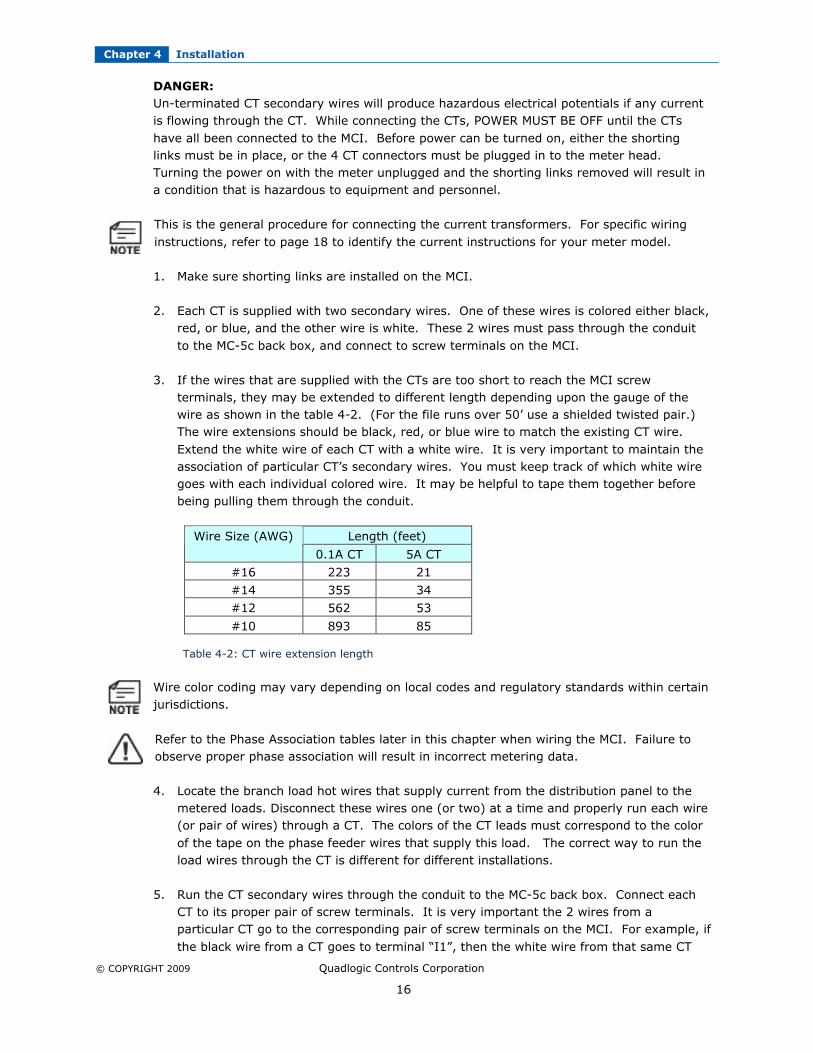
3. If the wires that are supplied with the CTs are too short to reach the MCI screwterminals, they may be extended to different length depending upon the gauge of thewire as shown in the table 4-2. (For the file runs over 50’ use a shielded twisted pair.)The wire extensions should be black, red, or blue wire to match the existing CT wire.
Extend the white wire of each CT with a white wire. It is very important to maintain theassociation of particular CT’s secondary wires. You must keep track of which white wiregoes with each individual colored wire. It may be helpful to tape them together beforebeing pulling them through the conduit.
Length (feet)Wire Size (AWG)
0.1A CT 5A CT
#16 223 21
#14 355 34
#12 562 53
#10 893 85
Table 4-2: CT wire extension length
Wire color coding may vary depending on local codes and regulatory standards within certainjurisdictions.
Refer to the Phase Association tables later in this chapter when wiring the MCI. Failure toobserve proper phase association will result in incorrect metering data.
4. Locate the branch load hot wires that supply current from the distribution panel to themetered loads. Disconnect these wires one (or two) at a time and properly run each wire(or pair of wires) through a CT. The colors of the CT leads must correspond to the color
of the tape on the phase feeder wires that supply this load. The correct way to run theload wires through the CT is different for different installations.
5. Run the CT secondary wires through the conduit to the MC-5c back box. Connect eachCT to its proper pair of screw terminals. It is very important the 2 wires from aparticular CT go to the corresponding pair of screw terminals on the MCI. For example, if
the black wire from a CT goes to terminal “I1”, then the white wire from that same CT

Chapter 4 Installation
© COPYRIGHT 2009 Quadlogic Controls Corporation
17
must go to terminal “N1”. The actual arrangement of the CT connections depends on theinstallation configuration.
6. Repeat items 4 and 5 (above) for each CT until all CTs have been installed andconnected to the MCI screw terminals.
7. Step 4 is complete if the shorting links are in place, the power can now be turned on.However, if you are installing the meter head immediately, leave the power off until themeter head has been installed.
Step 5: Install equipment and covers
It is much better to do this step with the power off. However, if it is not possible to turn thepower off, this step can be done with power on. If power is on and meter head is unplugged,
SHORTING LINKS MUST BE IN PLACE.
1. Plug the 4 Current connectors, labeled CT1, CT2, CT3, and CT4 into the correspondingconnectors in the back of the meter head. The connectors are color-coded and polarized.Make sure that the color of the plugs matches the color of the connectors on the meterhead. There are 2 connectors of each color, but they will only plug in one way because
one of the connectors has male pins, and the other has female pins. If a connector doesnot mate easily, try the other same-colored connector.
2. If the optional Communications Module is installed, there will be a 4-pin connector on theend of a wire coming out of the MC-5c meter head. Plug this connector into its mateconnector which is on the end of a wire that goes into the Communications Module
housing.
3. Plug the voltage connector from the fuse block (see figure 3-1) into the back of themeter head.
4. Make certain that the current connectors voltage connectors and ribbon cable on the
meter head are all plugged in securely and correctly.
5. Remove the shorting links from the MCI.
6. Close cover and secure with provided screw.
7. If power was off, turn it on.
8. Installation is complete. The LCD on the MC-5c meter head should be displaying lettersand numbers. The meter is ready for testing and certification.
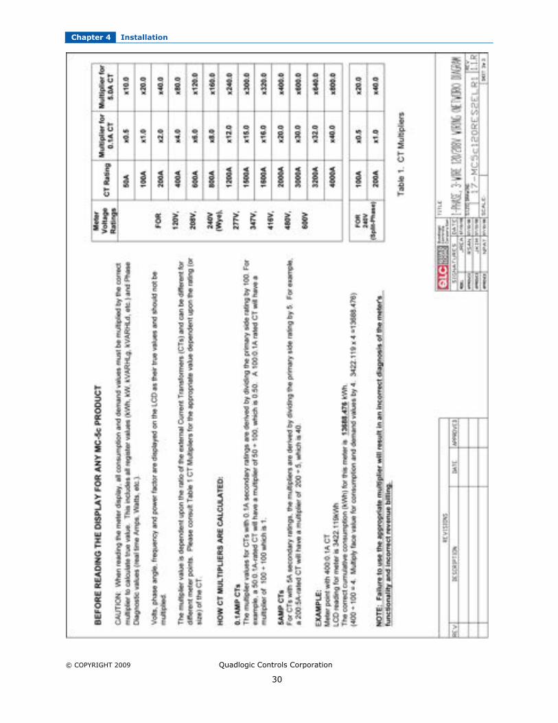
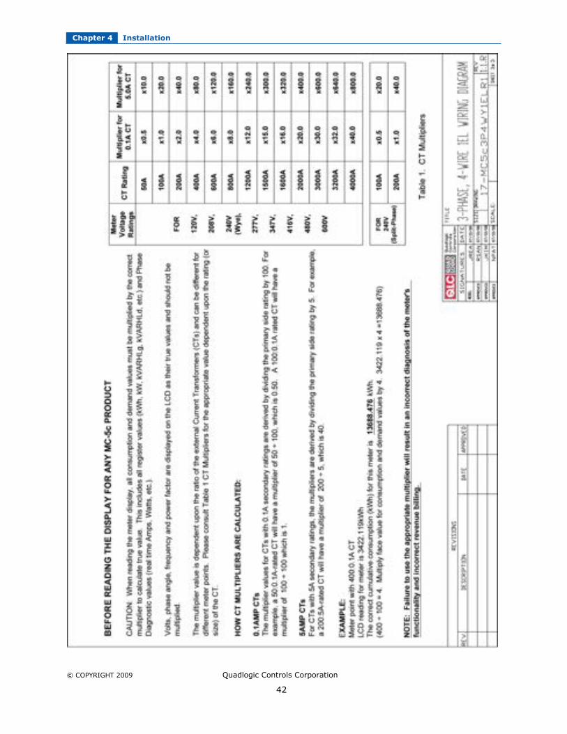
CAUTION:
When reading the meter display, all consumption and demand values must be multiplied bythe correct multiplier to calculate true value.
Please refer to Chapter 6: Applying Multipliers.
Chapter 4 Installation
© COPYRIGHT 2009 Quadlogic Controls Corporation
18
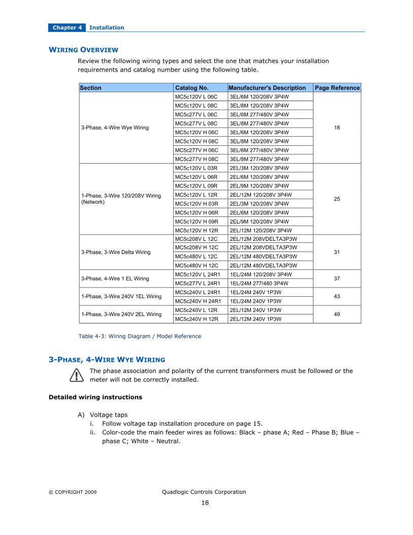
WIRING OVERVIEW
Review the following wiring types and select the one that matches your installationrequirements and catalog number using the following table.
Section Catalog No. Manufacturer's Description Page Reference
MC5c120V L 06C 3EL/6M 120/208V 3P4W
MC5c120V L 08C 3EL/8M 120/208V 3P4W
MC5c277V L 06C 3EL/6M 277/480V 3P4W
MC5c277V L 08C 3EL/8M 277/480V 3P4W
MC5c120V H 06C 3EL/6M 120/208V 3P4W
MC5c120V H 08C 3EL/8M 120/208V 3P4W
MC5c277V H 06C 3EL/6M 277/480V 3P4W
3-Phase, 4-Wire Wye Wiring
MC5c277V H 08C 3EL/8M 277/480V 3P4W
18
MC5c120V L 03R 2EL/3M 120/208V 3P4W
MC5c120V L 06R 2EL/6M 120/208V 3P4W
MC5c120V L 09R 2EL/9M 120/208V 3P4W
MC5c120V L 12R 2EL/12M 120/208V 3P4W
MC5c120V H 03R 2EL/3M 120/208V 3P4W
MC5c120V H 06R 2EL/6M 120/208V 3P4W
MC5c120V H 09R 2EL/9M 120/208V 3P4W
1-Phase, 3-Wire 120/208V Wiring (Network)
MC5c120V H 12R 2EL/12M 120/208V 3P4W
25
MC5c208V L 12C 2EL/12M 208VDELTA3P3W
MC5c208V H 12C 2EL/12M 208VDELTA3P3W
MC5c480V L 12C 2EL/12M 480VDELTA3P3W 3-Phase, 3-Wire Delta Wiring
MC5c480V H 12C 2EL/12M 480VDELTA3P3W
31
MC5c120V L 24R1 1EL/24M 120/208V 3P4W 3-Phase, 4-Wire 1 EL Wiring
MC5c277V L 24R1 1EL/24M 277/480 3P4W37
MC5c240V L 24R1 1EL/24M 240V 1P3W 1-Phase, 3-Wire 240V 1EL Wiring
MC5c240V H 24R1 1EL/24M 240V 1P3W43
MC5c240V L 12R 2EL/12M 240V 1P3W 1-Phase, 3-Wire 240V 2EL Wiring
MC5c240V H 12R 2EL/12M 240V 1P3W49
Table 4-3: Wiring Diagram / Model Reference
3-PHASE, 4-WIRE WYE WIRING
The phase association and polarity of the current transformers must be followed or themeter will not be correctly installed.
Detailed wiring instructions
A) Voltage tapsi. Follow voltage tap installation procedure on page 15.ii. Color-code the main feeder wires as follows: Black – phase A; Red – Phase B; Blue –
phase C; White – Neutral.

Chapter 4 Installation
© COPYRIGHT 2009 Quadlogic Controls Corporation
19
iii. Connect #12 AWG wires to phase A, phase B, phase C, and Neutral. Wires must beBlack (phase A), Red (phase B), Blue (phase C), and White (Neutral)
iv. If required, run the hot wires through a disconnect switch (if fused, use 15A ‘FastActing’ fuses.)
v. Run wires through conduit to MC-5c back box. Connect to screw terminals on fuseblock. Black – VA; Red – VB; Blue – VC; White – N
B) CT installationi. Follow CT installation procedure on page 15.ii. For each load, determine which voltage phase supplies the power. Then use a CT
with the corresponding color code for that load (Black, Red, or Blue).
iii. Route the load wire through the CT as shown in the diagramiv. Connect the CT secondary wires to the MCI according to the following procedure:
Chapter 4 Installation
© COPYRIGHT 2009 Quadlogic Controls Corporation
20
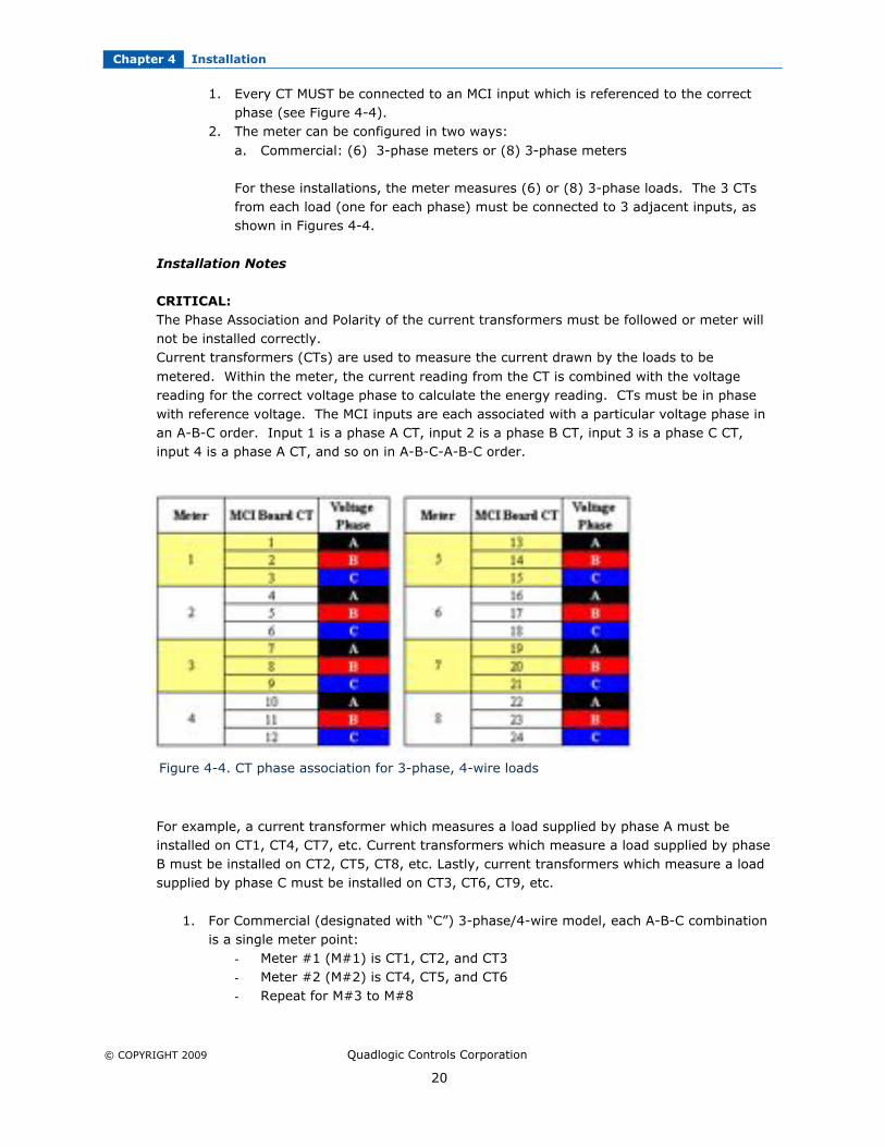
1. Every CT MUST be connected to an MCI input which is referenced to the correctphase (see Figure 4-4).
2. The meter can be configured in two ways:
a. Commercial: (6) 3-phase meters or (8) 3-phase meters
For these installations, the meter measures (6) or (8) 3-phase loads. The 3 CTsfrom each load (one for each phase) must be connected to 3 adjacent inputs, asshown in Figures 4-4.
Installation Notes
CRITICAL:
The Phase Association and Polarity of the current transformers must be followed or meter willnot be installed correctly.Current transformers (CTs) are used to measure the current drawn by the loads to be
metered. Within the meter, the current reading from the CT is combined with the voltagereading for the correct voltage phase to calculate the energy reading. CTs must be in phasewith reference voltage. The MCI inputs are each associated with a particular voltage phase inan A-B-C order. Input 1 is a phase A CT, input 2 is a phase B CT, input 3 is a phase C CT,input 4 is a phase A CT, and so on in A-B-C-A-B-C order.
Figure 4-4. CT phase association for 3-phase, 4-wire loads
For example, a current transformer which measures a load supplied by phase A must beinstalled on CT1, CT4, CT7, etc. Current transformers which measure a load supplied by phaseB must be installed on CT2, CT5, CT8, etc. Lastly, current transformers which measure a loadsupplied by phase C must be installed on CT3, CT6, CT9, etc.
1. For Commercial (designated with “C”) 3-phase/4-wire model, each A-B-C combinationis a single meter point:
- Meter #1 (M#1) is CT1, CT2, and CT3- Meter #2 (M#2) is CT4, CT5, and CT6- Repeat for M#3 to M#8
Chapter 4 Installation
© COPYRIGHT 2009 Quadlogic Controls Corporation
21
2. Follow local codes for installation requirement, e.g. conduit, fused disconnect,distance, and wiring.
3. For six (6) 3-phase metering points, model numbers:a) MC5c 120V L 06Cb) MC5c 277V L 06Cc) MC5c 120V H 06Cd) MC5c 277V H 06C
Use meter points M#1-M#6. M#7 and M#8 are not configured for operation.
CAUTION:
If breakers are energized, shorting links must be installed before: a) Disconnecting the CT headers or
b) Replacing or installing meter heads on the panel.
WARNING:
Bodily injury or damage may result if shorting links are not installed.

Chapter 4 Installation
© COPYRIGHT 2009 Quadlogic Controls Corporation
22
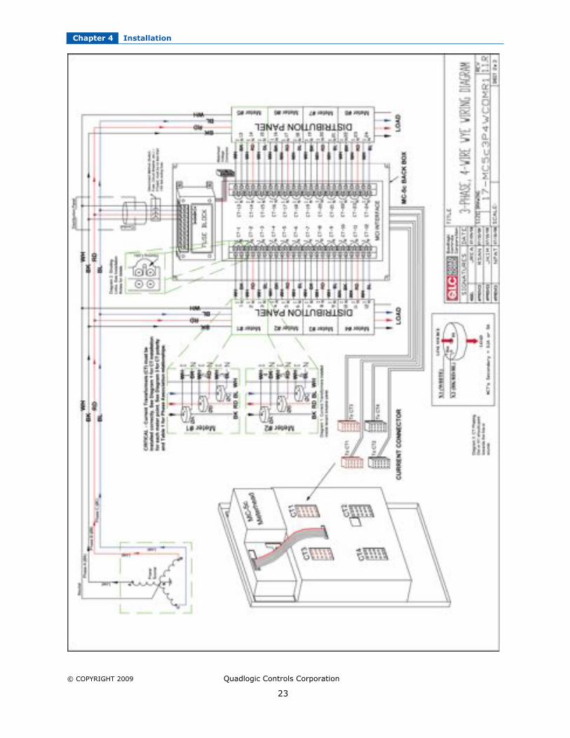
Figure 4-5. 3-phase, 4-wire wye wiring
Chapter 4 Installation
© COPYRIGHT 2009 Quadlogic Controls Corporation
23

Chapter 4 Installation
© COPYRIGHT 2009 Quadlogic Controls Corporation
24

Chapter 4 Installation
© COPYRIGHT 2009 Quadlogic Controls Corporation
25
1-PHASE, 3-WIRE 120/208V WIRING (NETWORK)
The phase association and polarity of the current transformers must be followed or the meterwill not be correctly installed.
Detailed Wiring Instructions
A) Voltage tapsi. Follow voltage tap installation procedure on page 15.ii. Color-code the main feeder wires as follows: Black – phase A; Red – phase B; Blue –
phase C; White – Neutral.
iii. Connect #12 AWG wires to phase A, phase B, phase C, and Neutral. Wires must beBlack (phase A), Red (phase B), Blue (phase C), and White (Neutral)
iv. If required, run the hot wires through a disconnect switch (if fused, use 15A ‘FastActing’ fuses.)
v. Run wires through conduit to MC-5c back box. Connect to screw terminals on fuseblock. Black – VA; Red – VB; Blue – VC; White – N

Chapter 4 Installation
© COPYRIGHT 2009 Quadlogic Controls Corporation
26
B) CT installationi. Follow CT installation procedure on page 13.ii. For each load, determine which voltage phase supplies the power. Then use a CT
with the corresponding color code for that load (Black, Red, or Blue).iii. Route the load wire through the CT as shown in the diagramiv. Connect the CT secondary wires to the MCI according to the following procedure:v. Every CT MUST be connected to an MCI input which is referenced to the correct
phase (See Figure 4-6.)vi. This type of meter is configured as a Residential 2-phase meter. For these
installations, the meter measures (12) 2-phase loads. Each metered load has 2 CTs.The 2 CTs from a particular metered load must be connected to adjacent inputs asshown in the chart. Note that meter 1 uses phases A and B, meter 2 uses phases Cand A, meter 3 uses phases B and C, and so on.
Installation Notes
CRITICAL:
The Phase Association and Polarity of the current transformers must be followed or meter willnot be installed correctly.
1. Current transformers must be in phase with Reference Voltage. The MCI runs in an A-B-C phase rotation and each three CT connections repeat an A-B, C-A, and B-C order.
Figure 4-6. CT phase association for 1-phase, 3-wire 120/208V loads.
For example, current transformers installed in phase with A reference voltage must be installed onCT1, CT4, CT7, etc. Current transformers installed in phase with B reference voltage must beinstalled on CT2, CT5, CT8, etc. Current transformers installed in phase with C reference voltagemust be installed on CT3, CT6, CT9, etc.
2. Each A-B, C-A, and B-C combination is a single meter point (separated by yellow and white in the above chart):
- Meter #1 (M#1) is measuring CT1 and CT2- Meter #2 (M#2) is measuring CT3 and CT4- repeat for M#3 to M#12

Chapter 4 Installation
© COPYRIGHT 2009 Quadlogic Controls Corporation
27
3. After completing all current transformer terminations, connect the four (4) currentconnectors and then remove the twenty-four (24) shorting links.
4. Follow local codes for installation requirement, e.g. conduit, fused disconnect, distance,and wiring.
5. Installation of 0.1A inputs and CL10 or 5A inputs are the same. For 3R, 6R, and 9R 3-phase metering points use meter points M#1-M#3, M#1-M#6, and M#1-M#9,respectively. M#4-M#12, M#7-M#12, and M#10-M#12 are not functional for three (3),
six (6), and nine (9) 3-phase metering points, respectively.
CAUTION:
If breakers are energized, shorting links must be installed before:
a) Disconnecting the CT headers or b) Replacing or installing meter heads on the panel.
WARNING:
Bodily injury or damage may result if shorting links are not installed.

Chapter 4 Installation
© COPYRIGHT 2009 Quadlogic Controls Corporation
28
Figure 4-7. 1-phase, 3-wire 120/208V wiring

Chapter 4 Installation
© COPYRIGHT 2009 Quadlogic Controls Corporation
29
Chapter 4 Installation
© COPYRIGHT 2009 Quadlogic Controls Corporation
30
Chapter 4 Installation
© COPYRIGHT 2009 Quadlogic Controls Corporation
31
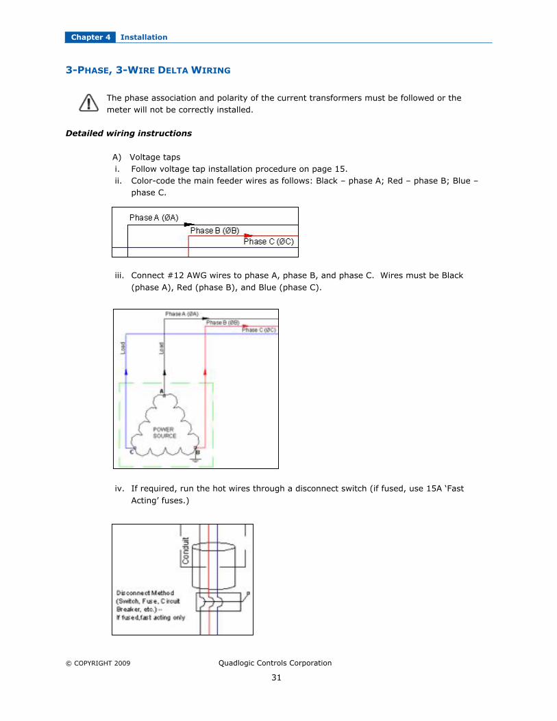
3-PHASE, 3-WIRE DELTA WIRING
The phase association and polarity of the current transformers must be followed or themeter will not be correctly installed.
Detailed wiring instructions
A) Voltage tapsi. Follow voltage tap installation procedure on page 15.ii. Color-code the main feeder wires as follows: Black – phase A; Red – phase B; Blue –
phase C.
iii. Connect #12 AWG wires to phase A, phase B, and phase C. Wires must be Black
(phase A), Red (phase B), and Blue (phase C).
iv. If required, run the hot wires through a disconnect switch (if fused, use 15A ‘Fast
Acting’ fuses.)

Chapter 4 Installation
© COPYRIGHT 2009 Quadlogic Controls Corporation
32
v. Run wires through conduit to MC5 back box. Connect to screw terminals on fuseblock. Black – VA; Red – VB; Blue – VC.
B) CT installationi. Follow CT installation procedure on page 15.ii. For each load, determine which voltage phase supplies the power. Then use a CT with
the corresponding color code for that load (Black or Blue). Note: The Red phase is notdirectly measured with a CT.
iii. Route the load wire through the CT as shown in the diagramiv. Connect the CT secondary wires to the MCI according to the following procedure:v. Every CT MUST be connected to an MCI input which is referenced to the correct phase
(See Figure 4-8).
This type of meter is configured as a Commercial meter with (12) 2-phase meters. For these
installations, the meter measures (12) 2-phase loads. Each metered load has 2 CTs. The 2CTs from a particular metered load must be connected to adjacent inputs as shown in thechart. Note that meter 1 uses phases A and C, meter 2 uses phases A and C, meter 3 usesphases A and C, and so on.
Installation Notes
CRITICAL:
The Phase Association and Polarity of the current transformers must be followed or meterwill not be installed correctly.
1. Current transformers must be in phase with Reference Voltage. The MCI runs in anA-C phase rotation (See Figure 4-8) and each two CT connections repeat an A-C, A-C, A-C pattern
Chapter 4 Installation
© COPYRIGHT 2009 Quadlogic Controls Corporation
33
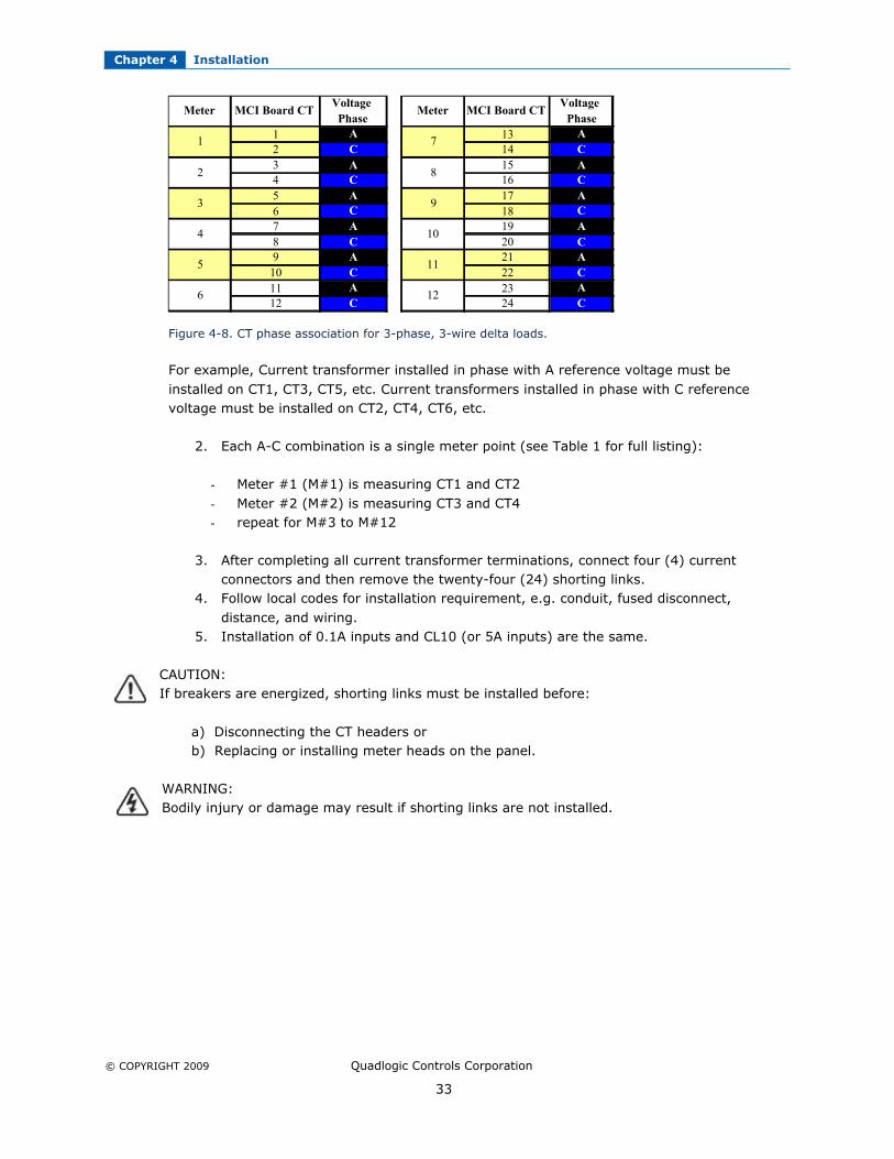
Figure 4-8. CT phase association for 3-phase, 3-wire delta loads.
For example, Current transformer installed in phase with A reference voltage must be
installed on CT1, CT3, CT5, etc. Current transformers installed in phase with C referencevoltage must be installed on CT2, CT4, CT6, etc.
2. Each A-C combination is a single meter point (see Table 1 for full listing):
- Meter #1 (M#1) is measuring CT1 and CT2
- Meter #2 (M#2) is measuring CT3 and CT4- repeat for M#3 to M#12
3. After completing all current transformer terminations, connect four (4) currentconnectors and then remove the twenty-four (24) shorting links.
4. Follow local codes for installation requirement, e.g. conduit, fused disconnect,
distance, and wiring.5. Installation of 0.1A inputs and CL10 (or 5A inputs) are the same.
CAUTION:If breakers are energized, shorting links must be installed before:
a) Disconnecting the CT headers or b) Replacing or installing meter heads on the panel.
WARNING:Bodily injury or damage may result if shorting links are not installed.
Voltage Voltage
Phase Phase
1 A 13 A
2 C 14 C
3 A 15 A
4 C 16 C
5 A 17 A
6 C 18 C
7 A 19 A
8 C 20 C
9 A 21 A
10 C 22 C
11 A 23 A
12 C 24 C
2
3
Meter MCI Board CTMeter MCI Board CT
4
5
6
7
8
9
10
11
12
1

Chapter 4 Installation
© COPYRIGHT 2009 Quadlogic Controls Corporation
34
Figure 4-9. 3-phase, 3-wire delta wiring

Chapter 4 Installation
© COPYRIGHT 2009 Quadlogic Controls Corporation
35

Chapter 4 Installation
© COPYRIGHT 2009 Quadlogic Controls Corporation
36
Chapter 4 Installation
© COPYRIGHT 2009 Quadlogic Controls Corporation
37
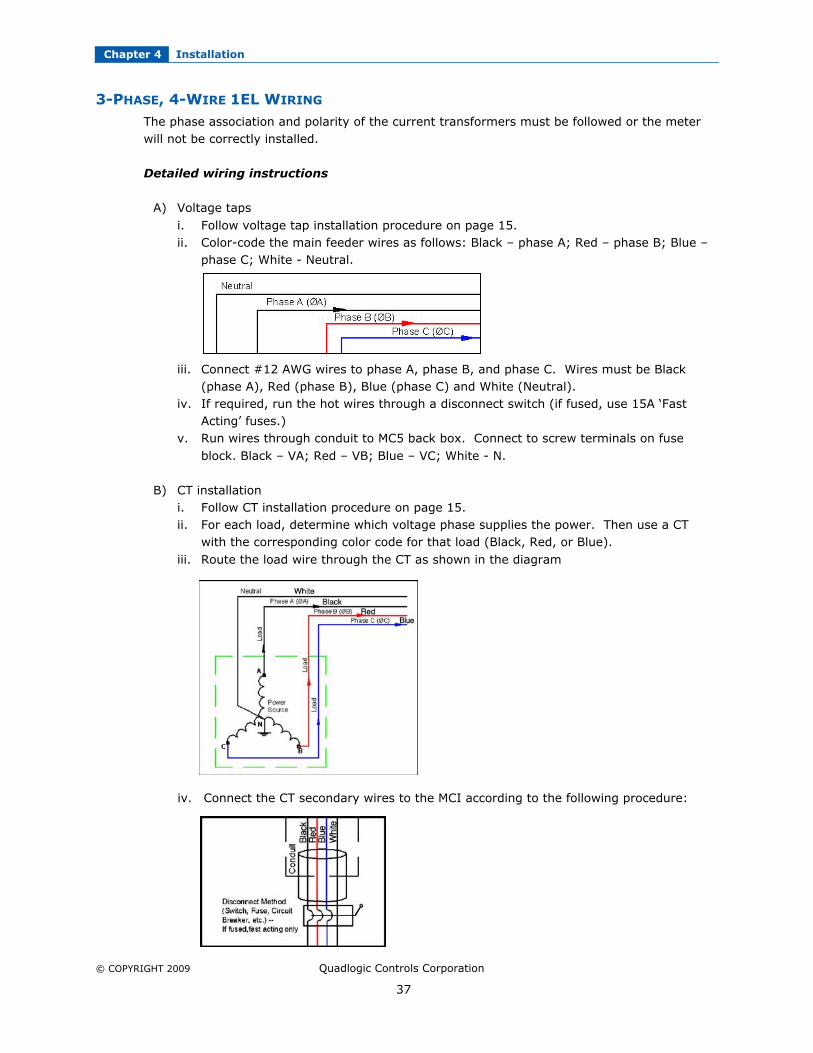
3-PHASE, 4-WIRE 1EL WIRING
The phase association and polarity of the current transformers must be followed or the meterwill not be correctly installed.
Detailed wiring instructions
A) Voltage taps
i. Follow voltage tap installation procedure on page 15.ii. Color-code the main feeder wires as follows: Black – phase A; Red – phase B; Blue –
phase C; White - Neutral.
iii. Connect #12 AWG wires to phase A, phase B, and phase C. Wires must be Black(phase A), Red (phase B), Blue (phase C) and White (Neutral).
iv. If required, run the hot wires through a disconnect switch (if fused, use 15A ‘FastActing’ fuses.)
v. Run wires through conduit to MC5 back box. Connect to screw terminals on fuse
block. Black – VA; Red – VB; Blue – VC; White - N.
B) CT installationi. Follow CT installation procedure on page 15.ii. For each load, determine which voltage phase supplies the power. Then use a CT
with the corresponding color code for that load (Black, Red, or Blue).
iii. Route the load wire through the CT as shown in the diagram
iv. Connect the CT secondary wires to the MCI according to the following procedure:

Chapter 4 Installation
© COPYRIGHT 2009 Quadlogic Controls Corporation
38
v. Every CT MUST be connected to an MCI input which is referenced to the correctphase (see Figure 4-8.)
vi. This type of meter is configured as a Residential meter with (24) single-phasemeters. For these installations, the meter measures (24) single-phase loads. Eachmetered load has one CT. The CT from a particular metered load must be connected
to adjacent inputs as shown in the chart. Note that Meter 1 uses phase A, Meter 2uses phases B, Meter 3 uses phases C, and so on.
Installation Notes
CRITICAL:
The Phase Association and Polarity of the current transformers must be followed or meter willnot be installed correctly.
1. Current transformers must be in phase with Reference Voltage. The MCI runs in an A-B-Cphase rotation and each CT connections repeat an A, B, C pattern.
Meter MCI Board CT Voltage Phase Meter MCI Board CT Voltage Phase
1 1 A 13 13 A
2 2 B 14 14 B
3 3 C 15 15 C
4 4 A 16 16 A
5 5 B 17 17 B
6 6 C 18 18 C
7 7 A 19 19 A
8 8 B 20 20 B
9 9 C 21 21 C
10 10 A 22 22 A
11 11 B 23 23 B
12 12 C 24 24 C
Figure 4-10. CT phase association for single-phase, 2-wire loads.
For example, Current transformer installed in phase with A reference voltage must be installedon CT1, CT4, CT7, etc. Current transformers installed in phase with B reference voltage must
be installed on CT2, CT5, CT8, etc. Current transformers installed in phase with C referencevoltage must be installed on CT3, CT6, CT9, etc.

Chapter 4 Installation
© COPYRIGHT 2009 Quadlogic Controls Corporation
39
2. Each phase is a single meter point (see Figure 4-10 for full listing):
- Meter #1 (M#1) is measuring CT1- Meter #2 (M#2) is measuring CT2- Meter #3 (M#3) is measuring CT3- repeat for M#4 to M#24
3. After completing all current transformer terminations, connect four (4) current connectors
and then remove the twenty-four (24) shorting links.4. Follow local codes for installation requirement, e.g. conduit, fused disconnect, distance,
and wiring.5. Installation of 0.1A inputs and CL10 (or 5A inputs) are the same.
CAUTION:
If breakers are energized, shorting links must be installed before: a) Disconnecting the CT headers or
b) Replacing or installing meter heads on the panel.
WARNING:
Bodily injury or damage may result if shorting links are not installed.

Chapter 4 Installation
© COPYRIGHT 2009 Quadlogic Controls Corporation
40
Figure 4-11. 3-phase, 4-wire 1EL wiring

Chapter 4 Installation
© COPYRIGHT 2009 Quadlogic Controls Corporation
41
Chapter 4 Installation
© COPYRIGHT 2009 Quadlogic Controls Corporation
42

Chapter 4 Installation
© COPYRIGHT 2009 Quadlogic Controls Corporation
43
1-PHASE, 3-WIRE 240V 1EL WIRING
The phase association and polarity of the current transformers must be followed or the meter
will not be correctly installed.
Detailed wiring instructions
A) Voltage tapsi. Follow voltage tap installation procedure on page 15.
ii. Color-code the main feeder wires as follows: Black – Line 1; Red – Line 2.iii. Connect #12 AWG wires to Line 1 and Line 2. Wires must be Black (Line 1)
and Red (Line 2).
iv. If required, run the hot wires through a disconnect switch (if fused, use no lessthan 15A ‘Fast Acting’ fuses.)
v. Run wires through conduit to MC5 back box. Connect to screw terminals onfuse block. Black – VA; Red – VB.
Chapter 4 Installation
© COPYRIGHT 2009 Quadlogic Controls Corporation
44
B) CT installationi. Follow CT installation procedure on page 15.ii. For each load, determine which voltage phase supplies the power. Then use a CT
with the corresponding color code for that load (Black or Red).iii. Route the load wire through the CT as shown in the diagram
iv. Connect the CT secondary wires to the MCI according to the following procedure:v. Every CT MUST be connected to an MCI input which is referenced to the correct
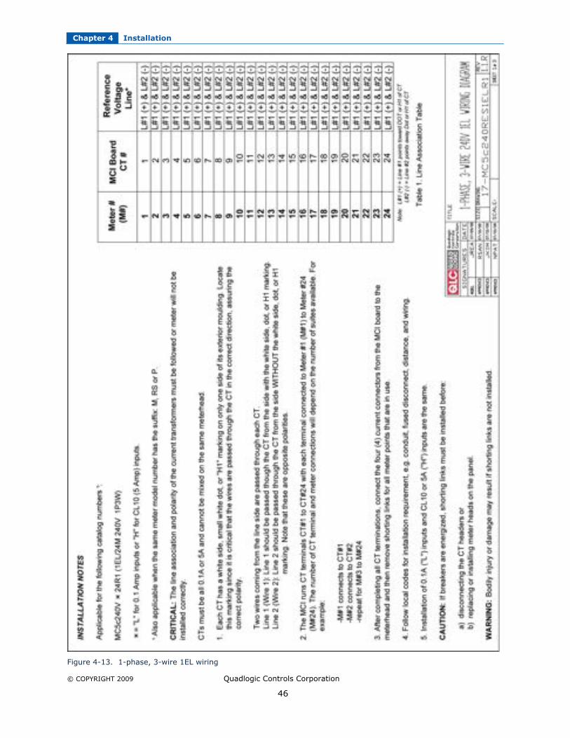
phase (see chart).vi. This type of meter is configured as a Residential meter with (24) 1-phase meters.
For these installations, the meter measures (24) 1-phase loads. Each metered loadhas 1 CT. The single CT from a particular metered load must be connected to
adjacent inputs as shown in the chart. Note that ALL meter points use Line 1 andLine 2.
Installation Notes
CRITICAL:
The Phase Association and Polarity of the current transformers must be followed or meter willnot be installed correctly.
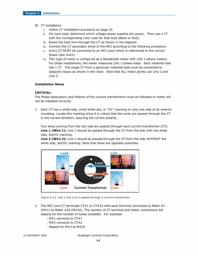
1. Each CT has a white side, small white dot, or "H1" marking on only one side of its exteriormoulding. Locate this marking since it is critical that the wires are passed through the CTin the correct direction, assuring the correct polarity.
Two wires coming from the line side are passed through each current transformer (CT).Line 1 (Wire 1): Line 1 should be passed through the CT from the side with the whiteside, dot/H1 marking.Line 2 (Wire 2): Line 2 should be passed through the CT from the side WITHOUT thewhite side, dot/H1 marking. Note that these are opposite polarities.
Figure 4-12. Line 1 and Line 2 passed through a current transformer.
2. The MCI runs CT terminals CT#1 to CT#24 with each terminal connected to Meter #1(M#1) to Meter #24 (M#24). The number of CT terminal and meter connections willdepend on the number of suites available. For example:
- M#1 connects to CT#1 - M#2 connects to CT#2
- Repeat for M#3 to M#24

Chapter 4 Installation
© COPYRIGHT 2009 Quadlogic Controls Corporation
45
3. After completing all current transformer terminations, connect four (4) current connectorsand then remove the twenty-four (24) shorting links.
4. Follow local codes for installation requirement, e.g. conduit, fused disconnect, distance,and wiring.
5. Installation of 0.1A inputs and CL10 or 5A inputs are the same. For 12R and 24R usemeter points M#1-M#12 and M#1-M#24, respectively. M#13-M#24 is not functional for
Model 12R.
CAUTION:
If breakers are energized, shorting links must be installed before:a) Disconnecting the CT headers or
b) Replacing or installing meter heads on the panel.
Bodily injury or damage may result if shorting links are not installed.
Chapter 4 Installation
© COPYRIGHT 2009 Quadlogic Controls Corporation
46
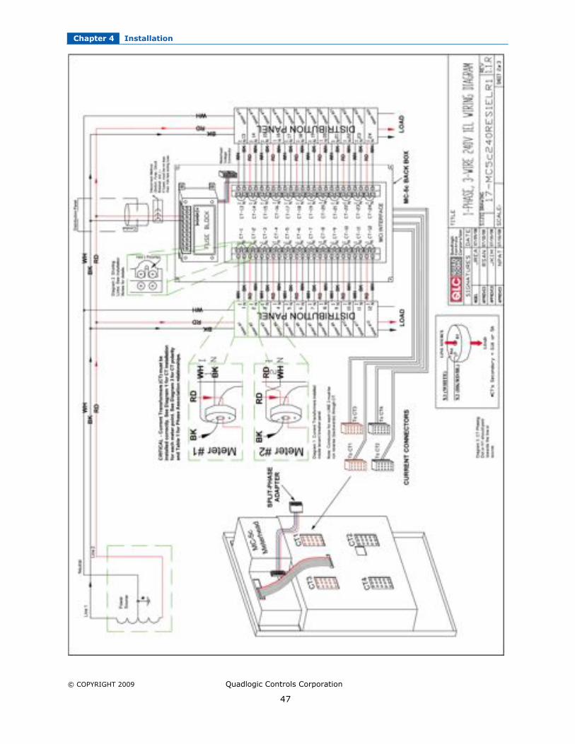
Figure 4-13. 1-phase, 3-wire 1EL wiring
Chapter 4 Installation
© COPYRIGHT 2009 Quadlogic Controls Corporation
47
Chapter 4 Installation
© COPYRIGHT 2009 Quadlogic Controls Corporation
48
Chapter 4 Installation
© COPYRIGHT 2009 Quadlogic Controls Corporation
49
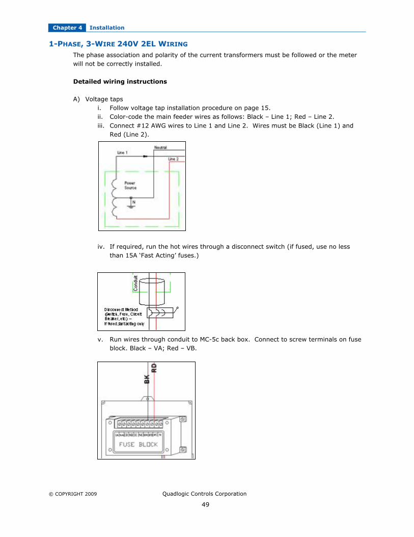
1-PHASE, 3-WIRE 240V 2EL WIRING
The phase association and polarity of the current transformers must be followed or the meterwill not be correctly installed.
Detailed wiring instructions
A) Voltage tapsi. Follow voltage tap installation procedure on page 15.ii. Color-code the main feeder wires as follows: Black – Line 1; Red – Line 2.
iii. Connect #12 AWG wires to Line 1 and Line 2. Wires must be Black (Line 1) andRed (Line 2).
iv. If required, run the hot wires through a disconnect switch (if fused, use no lessthan 15A ‘Fast Acting’ fuses.)
v. Run wires through conduit to MC-5c back box. Connect to screw terminals on fuseblock. Black – VA; Red – VB.

Chapter 4 Installation
© COPYRIGHT 2009 Quadlogic Controls Corporation
50
B) CT installationi. Follow CT installation procedure on page 15.
ii. For each load, determine which voltage phase supplies the power. Then use a CTwith the corresponding color code for that load (Black or Red).
iii. Route the load wire through the CT as shown in the diagramiv. Connect the CT secondary wires to the MCI according to the following procedure:v. Every CT MUST be connected to an MCI input which is referenced to the correct
phase (see chart).
vi. This type of meter is configured as a Residential meter with (12) 1-phase meters.For these installations, the meter measures (12) 1-phase loads. Each meteredload has 2 CT. The two CTs from a particular metered load must be connected toadjacent inputs as shown in the chart. Note that ALL meter points use Line 1 andLine 2.
Installation Notes
CRITICAL:
The Phase Association and Polarity of the current transformers must be followed or meter willnot be installed correctly.
1. Each CT has a white side, small white dot, or "H1" marking on only one side of itsexterior. Locate this marking as it is critical that the wires are passed through the CT inthe correct direction, assuring the correct polarity.
Two wires coming from the line side are passed through each current transformer (CT).
Line 1 (Wire 1): Line 1 should be passed through the CT from the side with the dot/H1marking.Line 2 (Wire 2): Line 2 should be passed through the CT from the side WITHOUT thedot/H1 marking. Note that these are opposite polarities (see Figure 4-14).
Figure 4-14. Line 1 and Line 2 passed through two different current transformers.

Chapter 4 Installation
© COPYRIGHT 2009 Quadlogic Controls Corporation
51
2. The MCI runs CT terminals CT#1 to CT#24 with two terminals connected to Meter #1(M#1) to Meter #12 (M#12). The number of CT terminal and meter connections willdepend on the number of suites available. For example,
- M#1 connects to CT#1 and CT#2 - M#2 connects to CT#3 and CT#4 - repeat for M#3 to M#1
3. After completing all current transformer terminations, connect four (4) current connectors
and then remove the twenty-four (24) shorting links.4. Follow local codes for installation requirement, e.g. conduit, fused disconnect, distance,
and wiring.5. Installation of 0.1A inputs and CL10 or 5A inputs are the same.
CAUTION:
If breakers are energized, shorting links must be installed before:
a) Disconnecting the CT headers or
b) Replacing or installing meter heads on the panel.
Bodily injury or damage may result if shorting links are not installed.

Chapter 4 Installation
© COPYRIGHT 2009 Quadlogic Controls Corporation
52
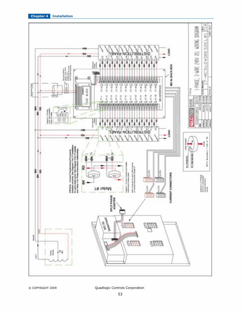
Figure 4-15. 1-phase, 3-wire 240V 2EL wiring
Chapter 4 Installation
© COPYRIGHT 2009 Quadlogic Controls Corporation
53

Chapter 4 Installation
© COPYRIGHT 2009 Quadlogic Controls Corporation
54

© COPYRIGHT 2009 Quadlogic Controls Corporation
55
CHAPTER 5
USING THE METER
DISPLAY NAVIGATION
The following figure shows the MC-5c user interface (LCD window) located on the front panelof the meter. It is easy to navigate the various sub-menus to read metering data, resetvalues and view configuration data.
Figure 5-1. MiniCloset-5 front panel display.
Press and hold the “Display Scroll” button, which is the small square button on the right sidewhen you are facing the meter. After two seconds, the LCD will display, REVERSE. If youcontinue to hold down the Display Scroll button, after another two seconds the LCD willdisplay FORWARD. These are simply directional indicators that you can use to navigate left
and right through the different menu register headings as shown on below. Each heading willbe displayed in two-second intervals. Note that the MC-5c defaults to the kWh register.
Meter LCD Headings:
Releasing the display scroll button at a given menu heading will allow you to cycle throughthe registers listed under the selected menu heading as shown in Figure 5-2, The DisplayMenu. For example, if the meter is in FORWARD mode and the Display Scroll button isreleased when the LCD reads “Serial # Registers”, each subsequent depression of the
Display Scroll button will show the following, in the order it appears below:
kWH kW Event Diagnostic
Registers Registers Registers
Serial # Phase Diagnostic PLC
Registers Registers Registers

Chapter 5 Using the Meter
© COPYRIGHT 2009 Quadlogic Controls Corporation
56
Serial #
Registers
Serial #
70005932
ASIC Version
FS1004F
Software Version
392b0136
Release Time
15:17 7/30/2005
Checksum
eee9f9b1
Hunt 19200 baud
8 b no parity
To reverse scrolling direction at either the heading level or within a submenu, press and holdthe display scroll button. When REVERSE is displayed after two seconds, release the display
scroll button. You can now go backwards through the menu selections by pressing andreleasing the display scroll button.
To go back to the forward scrolling option, follow the same procedure, except release thedisplay scroll button when FORWARD is displayed.
Caution:
When reading the meter display, all consumption and demand values must be multiplied bythe correct multiplier to calculate true value. Please refer to Chapter 6 for more details.

Chapter 5 Using the Meter
© COPYRIGHT 2009 Quadlogic Controls Corporation
57
Figure 5-2. The Display Menu Structure For an 8-meter point MC-5c.

Chapter 5 Using the Meter
© COPYRIGHT 2009 Quadlogic Controls Corporation
58
To follow is an explanation of each of the menu options under Phase Diagnostics Registers:
VERIFYING METER FUNCTIONALITY
It is very important to verify that the MC-5c and the CTs are properly installed. Follow the
steps below to verify the voltage, kWh reading, current, and energy.
I. Verifying Voltage
1. Press and hold the Display Scroll button until the following menu heading isdisplayed:
Chapter 5 Using the Meter
© COPYRIGHT 2009 Quadlogic Controls Corporation
59
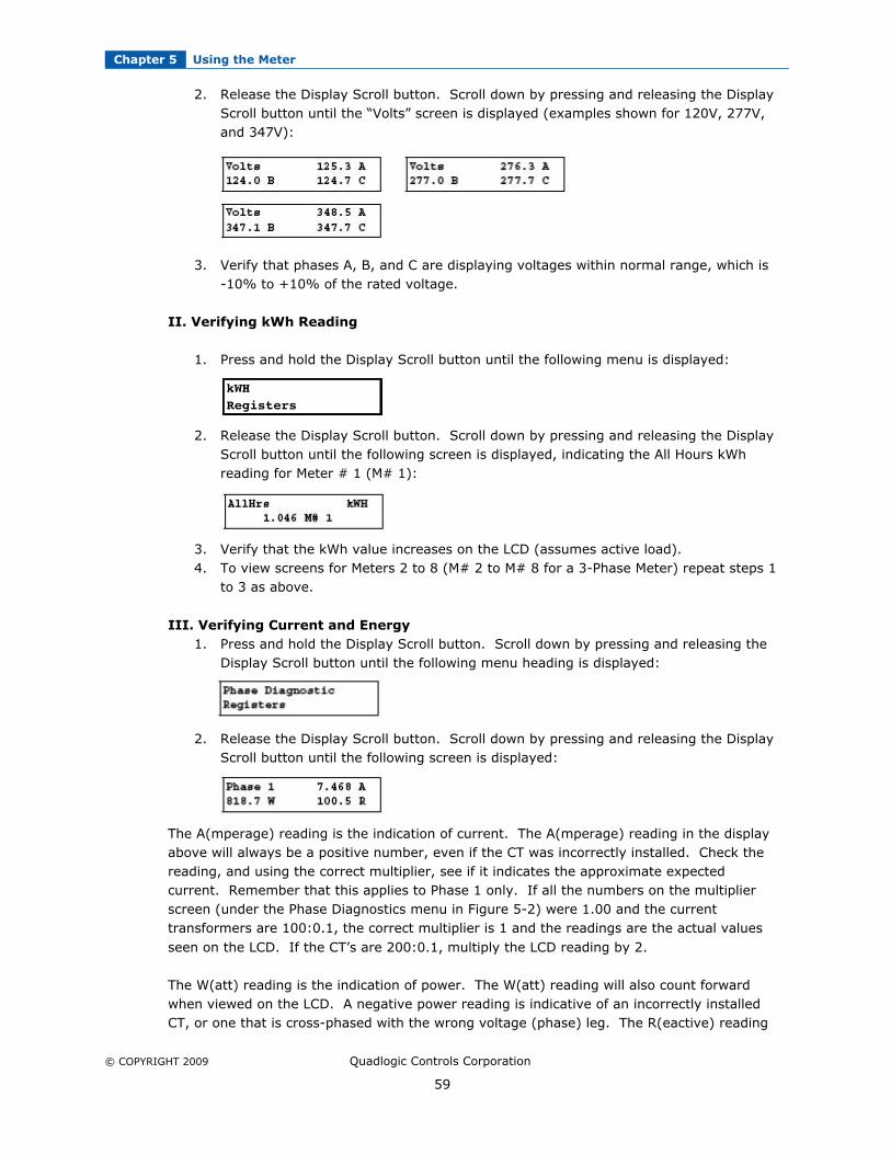
2. Release the Display Scroll button. Scroll down by pressing and releasing the DisplayScroll button until the “Volts” screen is displayed (examples shown for 120V, 277V,and 347V):
3. Verify that phases A, B, and C are displaying voltages within normal range, which is-10% to +10% of the rated voltage.
II. Verifying kWh Reading
1. Press and hold the Display Scroll button until the following menu is displayed:
2. Release the Display Scroll button. Scroll down by pressing and releasing the DisplayScroll button until the following screen is displayed, indicating the All Hours kWhreading for Meter # 1 (M# 1):
3. Verify that the kWh value increases on the LCD (assumes active load).4. To view screens for Meters 2 to 8 (M# 2 to M# 8 for a 3-Phase Meter) repeat steps 1
to 3 as above.
III. Verifying Current and Energy
1. Press and hold the Display Scroll button. Scroll down by pressing and releasing theDisplay Scroll button until the following menu heading is displayed:
2. Release the Display Scroll button. Scroll down by pressing and releasing the DisplayScroll button until the following screen is displayed:
The A(mperage) reading is the indication of current. The A(mperage) reading in the displayabove will always be a positive number, even if the CT was incorrectly installed. Check thereading, and using the correct multiplier, see if it indicates the approximate expectedcurrent. Remember that this applies to Phase 1 only. If all the numbers on the multiplierscreen (under the Phase Diagnostics menu in Figure 5-2) were 1.00 and the currenttransformers are 100:0.1, the correct multiplier is 1 and the readings are the actual values
seen on the LCD. If the CT’s are 200:0.1, multiply the LCD reading by 2.
The W(att) reading is the indication of power. The W(att) reading will also count forwardwhen viewed on the LCD. A negative power reading is indicative of an incorrectly installedCT, or one that is cross-phased with the wrong voltage (phase) leg. The R(eactive) reading
kWH
Registers

Chapter 5 Using the Meter
© COPYRIGHT 2009 Quadlogic Controls Corporation
60
can be negative, depending on the nature of the load. Negative values indicate a capacitiveload while positive values indicate an inductive load.
3. Scroll down by pressing and releasing the Display Scroll button until the followingscreen is displayed:
Under normal conditions the phase angle (x.x˚) should be between -30˚ and +30˚ and the
power factor should be a number between 0.80 – 1.0.
Power factor for inductive loads will typically be lower than that of resistive loads, typicallybetween 0.60 and 0.80.
If the phase angle on the lower left is a number close to 180˚ it indicates the CT was
installed backwards, or is 180˚ out-of-phase. If the angle is close to 120˚, at least two CTshave been cross-phased, and a similar number will appear in the phase angle data inPhase 2.
4. To view screens for phases 2 to 24, repeat steps 1 to 3 as above.
RESETTING DEMAND VALUES (FOR COMMERCIAL APPLICATIONS ONLY)
Use the following procedure to reset the Demand registers to zero:
BE CERTAIN TO RECORD THE CURRENT PEAK DEMAND (WITH THE TIME AND DATE) FOREACH METERING POINT MEASURED BY THE MC-5c, BEFORE RESETTING THE DEMAND.Once you reset the demand according to the instructions below, you cannot
retrieve any prior demands locally. If you are unsure, then using the above instructions,scroll through to the demand (kW) and record the demand value (kW) for each meteringpoint. (As a back up, locally resetting the demand will obviously not delete the demand from
the demand values already retrieved and stored in the meter, Transponder or software.)
1. Press and hold the Demand Reset button.
2. The LCD will initially display the Quadlogic Copyright message.3. The LCD will then display the Dmdreset event screen:
4. Keep the Demand Reset button depressed until the screen updates and displays the
current date and time. This signifies that the demand has been reset.

© COPYRIGHT 2009 Quadlogic Controls Corporation
61
CHAPTER 6
APPLYING MULTIPLIERS
READING THE DISPLAY
CAUTION:
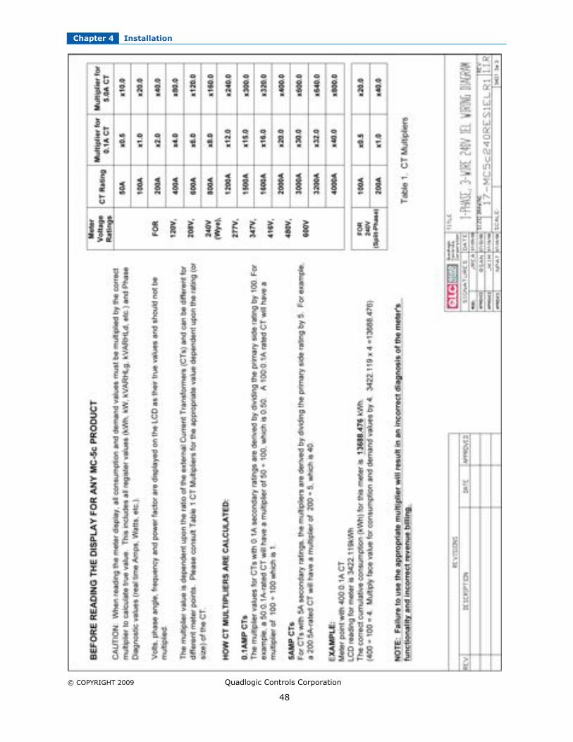
When reading the meter display, all consumption and demand values must be multiplied bythe correct multiplier to calculate true value. This includes all register values (kWh, kW,kVARHLg, kVARHLd, etc.) and Phase Diagnostic values (real time Amps, Watts, etc.).
Volts, phase angle, frequency and power factor are displayed on the LCD as their true valuesand should not be multiplied.
The multiplier value is dependent upon the ratio of the external Current Transformers (CTs)and can be different for different meter points. The following table MUST be used to obtainactual consumption and demand readings.
Meter Boltage
RatingsCT Rating
Multiplier for
0.1A CT
Multiplier for
5.0A CT
50A x0.5 X10.0
100A x1.0 X20.0
200A x2.0 X40.0
400A x4.0 X80.0
600A x6.0 X120.0
800A x8.0 X160.0
1200A x12.0 X240.0
1500A x15.0 X300.0
2000A x20.0 X400.0
3000A x30.0 X600.0
For120V,208V,230V,
240V (Wye),277V,347V,480V,600V
4000A x40.0 X800.0
Table 6.1 Standard multiplier table.
Meter BoltageRatings
CT RatingMultiplier for
0.1A CTMultiplier for
5.0A CT
100A X0.5 X20.0For 240V(Split-phase) 200A X1.0 X40.0
Table 6.2 Multiplier table for a 240V split-phase MiniCloset-5c meter.

Chapter 6 Applying Multipliers
© COPYRIGHT 2009 Quadlogic Controls Corporation
62
HOW CT MULTIPLIERS ARE CALCULATED
0.1Amp CTs
The multiplier values for CTs with 0.1A secondary ratings are derived by dividing the primaryside rating by 100. For example, a 50:0.1A-rated CT will have a multiplier of 50 ÷ 100,which is 0.50. A 100:0.1A rated CT will have a multiplier of 100 ÷ 100 which is 1. (Exceptfor 240V MC-5c meters.)5Amp CTsFor CTs with 5A secondary ratings, the multipliers are derived by dividing the primary side
rating by 5. For example, a 200:5A-rated CT will have a multiplier of 200 ÷ 5, which is 40.(Except for 240V MC-5c meters.)
Example:
Meter point with 400:0.1A CTLCD reading for meter is 3422.119kWh
The correct cumulative consumption (kWh) for this meter is 13688.476 kWh.(400 ÷ 100 = 4. Multiply face value for consumption and demand values by 4. 3422.119 x4 =13688.476)
The multiplier must be applied when calculating both kW and kWH readings on every screendisplayed on the LCD.
A 240V split-phase MiniCloset-5 meter is the ONLY meter type that has a different multiplierstructure (as shown in Table 6.2). This is due to the fact that internal multipliers werealready applied in the meter during the calibration process.
Failure to use the appropriate multiplier will result in an incorrect diagnosis of the meter’s
functionality and incorrect revenue billing.

© COPYRIGHT 2009 Quadlogic Controls Corporation
63
CHAPTER 7
COMMUNICATIONS
OVERVIEW
In addition to integrated PLC, Quadlogic meters have an optical port as a standard featureand an optional modem, RS-232, or RS-485 module through which communications with themeter can be established. Any computer with a terminal emulation program such asHyperTerminal Private Edition can be utilized. The meter utilizes ASCII text type commandsand responses for interrogation and programming.
HYPERTERMINAL PRIVATE EDITION SETUP
HyperTerminal Private Edition is one of the many terminal emulation programs that can beused to communicate with Quadlogic meters. Follow the procedures below to set up aHyperTerminal session suitable for meter communications.
1. Open HyperTerminal Private Edition. If the program is not yet installed in thecomputer, download the program from Hilgraeve’s website(http://www.hilgraeve.com/).
Commercial users need to purchase this program according to this software manufacturer’s
rules and regulations.
2. Enter the session name and click OK.
Figure 7-1. New Connection Window
3. Select the appropriate COM port that will be used for the optical coupler. The opticalcoupler will be used to communicate with the meter. This will be placed on the
optical port of the meter and held in place magnetically.

Chapter 7 Communications
© COPYRIGHT 2009 Quadlogic Controls Corporation
64
Figure 7-2. Connect To Window
4. Select the necessary parameters for communication. The session should be set at19200/8/N/1/N Click OK.
Figure 7-3. COM Port Properties Window
5. Go to the Properties window and select the Settings tab. Go to the ASCII Setup andcheck the “Echo typed characters locally” box. Click on OK.
Figure 7-4. ASCII Setup Window
Once HyperTerminal is setup, the user can now log in into the meter.

Chapter 7 Communications
© COPYRIGHT 2009 Quadlogic Controls Corporation
65
SECURITY HIERARCH
Quadlogic meters are protected by a security hierarchy of Level 1 (least secure) throughLevel 5 (most secure). Each level allows access to increasing data parameters and
manipulation of the meter. Once logged in at the specific level, access to that level and allthose levels below it are permitted. The levels are defined as follows:
Level 1 Reader Basic reading of meter data only
Level 2 Technician Access to TOU data
Level 3 Meter Superintendent Reading of all data (demand reset, time change, etc.),View TOU
Level 4 Utility Allows limited clearing and reprogramming of thedevice
Level 5 Meter Lab Allows full clearing and reprogramming of the device(Contact manufacturer.)
LOGGING IN TO THE METER
A Quadlogic meter is logged into by establishing proper communications and issuing the
following command set attn_–S<Serial Number>_-<Password><enter>.
The serial number of the meter is a unique 8-digit number assigned specifically to the meter.The password in the syntax depends on what security the user wants or was assigned. Thetable below lists the possible passwords that may be used at different security levels.
Passwords are case sensitive.
Level Number Level Description PasswordLevel 1 Reader 1reader1Level 2 Technician 2tech2Level 3 Meter Superintendent 3Super3
Figure 7-5. Login String
Chapter 7 Communications
© COPYRIGHT 2009 Quadlogic Controls Corporation
66
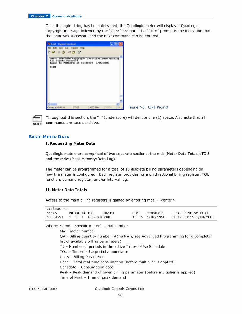
Once the login string has been delivered, the Quadlogic meter will display a QuadlogicCopyright message followed by the “CIP#” prompt. The “CIP#” prompt is the indication thatthe login was successful and the next command can be entered.
Figure 7-6. CIP# Prompt
Throughout this section, the “_” (underscore) will denote one (1) space. Also note that allcommands are case sensitive.
BASIC METER DATA
I. Requesting Meter Data
Quadlogic meters are comprised of two separate sections; the mdt (Meter Data Totals)/TOUand the mdw (Mass Memory/Data Log).
The meter can be programmed for a total of 16 discrete billing parameters depending onhow the meter is configured. Each register provides for a unidirectional billing register, TOUfunction, demand register, and/or interval log.
II. Meter Data Totals
Access to the main billing registers is gained by entering mdt_-T<enter>.
Where: Serno – specific meter’s serial number
M# - meter numberQ# - Billing quantity number (#1 is kWh, see Advanced Programming for a completelist of available billing parameters)T# - Number of periods in the active Time-of-Use ScheduleTOU – Time-of-Use period annunciatorUnits – Billing Parameter
Cons – Total real-time consumption (before multiplier is applied)Consdate – Consumption datePeak – Peak demand of given billing parameter (before multiplier is applied)Time of Peak – Time of peak demand
Chapter 7 Communications
© COPYRIGHT 2009 Quadlogic Controls Corporation
67
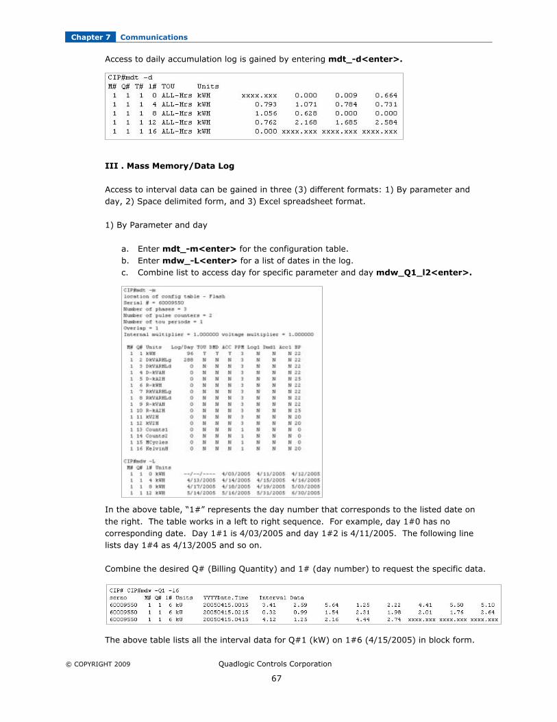
Access to daily accumulation log is gained by entering mdt_-d<enter>.
III . Mass Memory/Data Log
Access to interval data can be gained in three (3) different formats: 1) By parameter andday, 2) Space delimited form, and 3) Excel spreadsheet format.
1) By Parameter and day
a. Enter mdt_-m<enter> for the configuration table.b. Enter mdw_-L<enter> for a list of dates in the log.c. Combine list to access day for specific parameter and day mdw_Q1_l2<enter>.
In the above table, “1#” represents the day number that corresponds to the listed date on
the right. The table works in a left to right sequence. For example, day 1#0 has nocorresponding date. Day 1#1 is 4/03/2005 and day 1#2 is 4/11/2005. The following linelists day 1#4 as 4/13/2005 and so on.
Combine the desired Q# (Billing Quantity) and 1# (day number) to request the specific data.
The above table lists all the interval data for Q#1 (kW) on 1#6 (4/15/2005) in block form.

Chapter 7 Communications
© COPYRIGHT 2009 Quadlogic Controls Corporation
68
The YYYYDate.Time lists the end of interval time stamp and is read left to right in a similarfashion to the mdw_-L table. Each number, reading left to right indicates the peak kWreading for the next 15minute interval as shown below. For example, the peak kW at the
interval period ending at 04:00AM on 4/15/2005 was 2.64.
The characters “xxxx.xxx” denotes no power to the meter at the end of the interval.
2) Space Delimited Form
Entering the command mdw<enter> will list all the interval log data (for all billingparameters) in a space delimited format. It may be captured and for input in to variousother software platforms.
3) Excel Spreadsheet Form
Entering the command mdw_-E<enter> will list all interval log data in a format that can be
imported into Excel. The date column will then need to be formatted to an Excel format.
20050415.0015= Period
ending on April 15, 2005
at 12:15am
The unmultiplied kW
reading at this time was
3.41kW
12:30am 12:45am 1:00am 1:15am
Numbers indicate the unmultiplied peak kW readings at the following times:

Chapter 7 Communications
© COPYRIGHT 2009 Quadlogic Controls Corporation
69
IV. Phase Diagnostics
Quadlogic meters will display phase diagnostics data in real time for Volts, Amps, Watts, VAR
Lagging, Power Factor, Phase Angle, and by phase accumulation (i.e. for each phase and forthe total accumulation of the three phases)
V. Event Log
Quadlogic meters store an event log list and by event. To access the list enter event_-
d<enter>.
ADVANCED METER PROGRAMMING
VI. Setting Data
The meter requires the date and time to be set in the meter from the default which is
00:00:01 1/01/1990 Monday
The date can be displayed by the dt<enter> command. To change the date and time type inthe new date and time in the following format at the CIP# prompt

Chapter 7 Communications
© COPYRIGHT 2009 Quadlogic Controls Corporation
70
dt_hh:mm:ss_mm/dd/yyy
To verify the changes type in dt<enter> once again.
VII. Customizing the Display Scroll
The Quadlogic meter can be programmed with a custom display scroll table using thefollowing commands
1) disp_-d<enter> - Displays all available display registers.
2) disp_0_0_-s<enter> - Displays 0 0 register, kWH.3) disp_34_0_-s<enter> - Displays the serial number of the device.4) disp_-W1234<enter> - Writes the display scroll settings to the flash memory.5) disp_-s<enter> - Displays programmed registers.

© COPYRIGHT 2009 Quadlogic Controls Corporation
71
CHAPTER 8
TROUBLESHOOTING
RESOLVING METER ISSUES
Problem: Meter does not power up
• Make sure the voltage plug is connected to the meter head.• Measure voltage connections at fuse block (phase to neutral).
WYE meter models power phase A to neutral.
Delta meter models power phase A to phase B.• If expected voltage is present, check fuses at fuse block (black box located inside the
meter on the back panel).• 1 fuse for meter power (must be either 1/4th A for 120V or 1/8th A for 277 V).• 3 fuses for voltage measurements (4A).• If proper voltage is present at the fuse block and the internal fuses are good and LCD still
does not display anything, return meter head only for RMA repair. (It is not necessary toreturn meter box with fuse block.)
Problem: Zero voltage appears on the LCD
• Measure voltage connections at fuse block (phase to neutral) WYE meter models power phase A to neutral
Delta meter models power phase A to phase B• If expected volts are present, check fuses at fuse block (black box located inside the meter
on the back panel). 1 fuse for meter power (must be either 1/4th A for 120V or 1/8th A for 277 V) 3 fuses for voltage measurements (4A)
Problem: Negative watts
• CT is reversed. Check phase polarity of CT installation.• Verify proper connection of CT secondaries.• Verify proper connection of any contractor wire extension.• Confirm that the phase angle is between +30° and -30°.
Problem: Phase Angle not between +30°and -30°(see Figure 8-1 for Vector Diagram)
• If angle falls between 90° and 150° OR between –90° and –150°: the CT is installed on one of the incorrect phases
• If angle falls between 150° and –150°: the CT polarity is reversed OR the wires are reversed
• If angle falls between –30° and –90°:
that means the CT polarity is reversed AND the CT is installed on one of theincorrect phases
• If metering large inductive loads (e.g. Elevators, HVAC, pumps) phase diagnostics may notbe an accurate verification

Chapter 8 Troubleshooting
© COPYRIGHT 2009 Quadlogic Controls Corporation
72
Figure 8-1. Vector Diagram

© COPYRIGHT 2009 Quadlogic Controls Corporation
73
CHAPTER 9
REPAIR AND SPARE PARTS
REPAIR OR REPLACEMENT
Quadlogic requires prior approval and an assigned RMA (Return Merchandise Authorization)number before accepting any merchandise returns. An RMA request form which includes
complete repair and/or return for credit policies can be found on our website atwww.quadlogic.com. If you are returning equipment for credit, a 20% restocking fee shallapply. Note: RMA shipping charges to Quadlogic are the responsibility of the product owner.Quadlogic will return merchandise back to the customer via UPS Ground at no charge.(International Customers: Quadlogic will pay for standard cost of clearance through dutiesand customs for receipt of authorized return merchandise only. Clearance through duties
and customs is the customer’s responsibility for return shipments.)
SPARE PARTS
Below is a list of spare parts that can be purchased by a customer in the event that a part ofa MiniCloset-5 meter has been damaged.
A. Meter Head – Main component of the MiniCloset-5c. The Meter Head contains the Meter
Module, through which all signals transmit, events are recorded and meter data is stored.B. Fuse Block – Provides termination for the voltage taps. It supplies power and fuse
protection to the Meter Head.C. MC-5c Back Box – Metal box housing the metering device and the MCI board.D. MCI – MiniCloset Interface, provides termination for the current transformers (CT).E. Communications Module (option)

© COPYRIGHT 2009 Quadlogic Controls Corporation
74

© COPYRIGHT 2009 Quadlogic Controls Corporation
75
CHAPTER 10
MISCELLANEOUS
PREVENTIVE MAINTENANCE
There is no necessary preventive maintenance or inspection.
Use a soft dry cloth to clean the meter.
A Toshiba CR2032 coin battery is used in each device ONLY for the clock when power is lost,and is intended to be good for decades before replacement. The meter does not rely on thebattery, and the meter data is stored in non-volatile FLASH memory.
WARRANTY INFORMATION
Quadlogic Controls Corporation warrants its equipment for 3 years from the ship date againstdefects in material or workmanship when installed in accordance with manufacturer’sinstructions by qualified personnel. This warranty does not cover installation, removal,reinstallation or labor costs and excludes normal wear and tear. The warranty does not coverproduct which has been altered from its original manufactured condition due to faulty
installation, tampering, accident, neglect, abuse, force majeure or abnormal conditions ofoperation. Obligation under this warranty is limited to repair and/or replacement, atQuadlogic’s option, of the manufactured product and in no event shall Quadlogic be liable forconsequential or incidental damages.
RELEASE DATES
Manual QLC Part Number Revision Number Release DateMiniCloset-5c Manual MC5c_USMAN_R1.0.R 1.0.R 1.1.09
REVISION HISTORY
Date Page Change Description

© COPYRIGHT 2009 Quadlogic Controls Corporation
76
APPENDIX
THE COMMUNICATIONS MODULE
A Quadlogic meter or Scan Transponder can have an optional communications module thatwill allow the system to be interrogated remotely through a modem device or allow multipleQuadlogic devices to be connected in a network through a RS-485 device (see Figure A.1).

Appendix
© COPYRIGHT 2009 Quadlogic Controls Corporation
77
Figure A-1. MC-5c with modem installation.
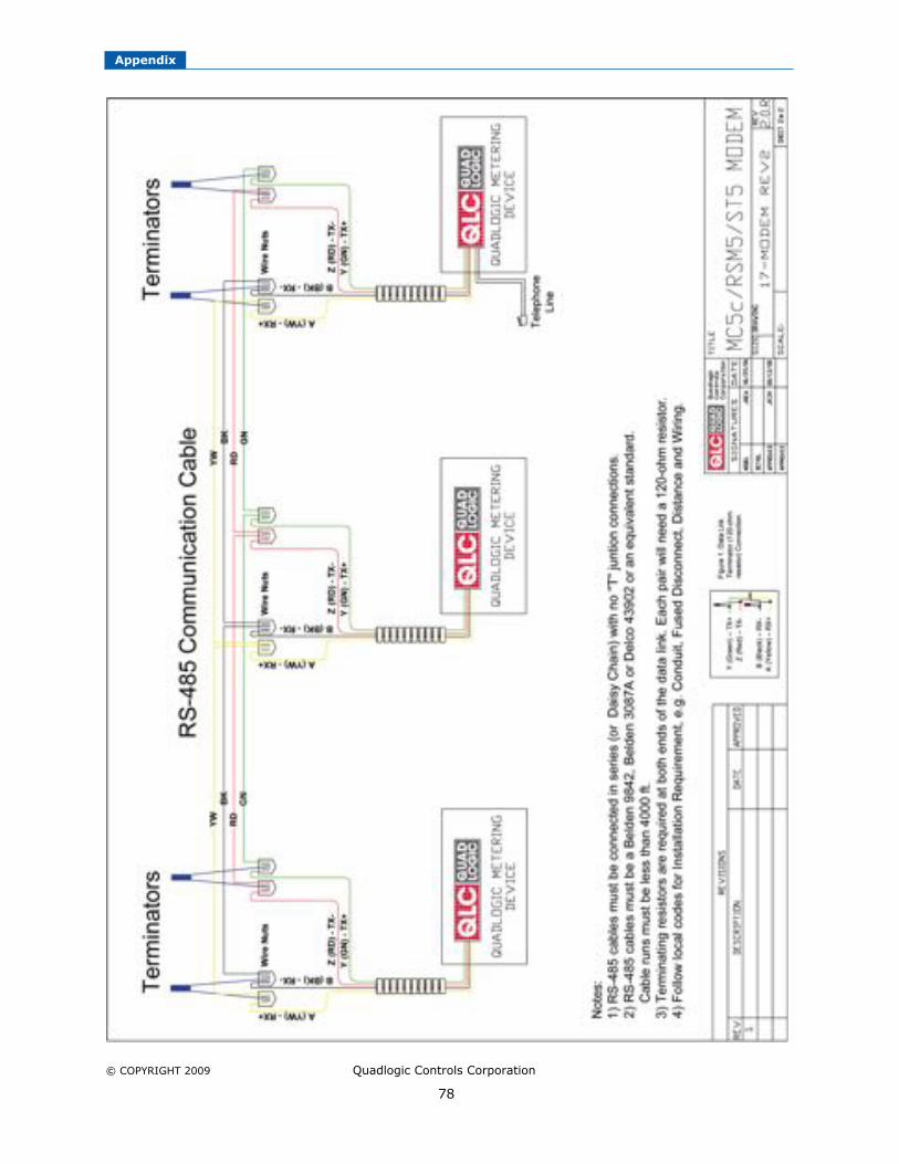
Appendix
© COPYRIGHT 2009 Quadlogic Controls Corporation
78
Appendix
© COPYRIGHT 2009 Quadlogic Controls Corporation
79
RS-485 OVERVIEW
Quadlogic devices may sometimes use a RS-485 interface to construct a multi-pointcommunications network. The RS-485 interface is connected in a 4-wire full-duplex mode
and is capable of handling 32 transmitters along with 32 receivers. In a four-wire network itis necessary that one node be a master node and all others be slaves. The network isconnected so that the master node communicates to all slave nodes and all slave nodescommunicate only with the master node.
GUIDELINES FOR PROPER WIRING OF A RS-485 NETWORK
Cable Selection1
Selecting data cable for a RS-485 system is important because intermittent communicationproblems are often caused by marginal cable and can be difficult to troubleshoot. The mostimportant parameters that dictate the type of cable that will be used are CharacteristicImpedance, Shunt Capacitance, and cable length or transmission run.
Characteristic Impedance (Ohms)
A value based on the inherent conductance, resistance, capacitance and inductance ofa cable that represents the impedance of an infinitely long cable. When the cable iscut to any length and terminated with this Characteristic Impedance, measurements of
the cable will be identical to values obtained from the infinite length cable. That is tosay that the termination of the cable with this impedance gives the cable theappearance of being infinite length, allowing no reflections of the transmitted signal.If termination is required in a system, the termination impedance value should matchthe Characteristic Impedance of the cable.
Shunt Capacitance (pF-ft)
The amount of equivalent capacitive load of the cable, typically listed in a per footbasis. One of the factors limiting total cable length is the capacitive load. Systemswith long lengths benefit from using low capacitance cable.
Cable Length (Transmission Run)
Typical RS-485 systems have a maximum transmission run of 4000 feet. The totaltransmission run will start from the first unit up to the last unit in the data linknetwork.
The type of cable used for RS-485 is typically a twisted-pair wire which is simply a pair of
wires with equal lengths and is twisted together. A twisted-pair wire helps prevent radiatedEMI and it also reduces the effects of received EMI. Because the two wires are close togetherand twisted, the noise received on one wire will tend to be the same as that received on thesecond wire. This type of noise is referred to as "common-mode noise." As RS-485 receiversare designed to look for signals that are the opposite of each other, they can easily rejectnoise that is common to both.
Recommended wires include Delco 43902, Belden 3087A, and Belden 9842.
1 http://www.arcelect.com/485info.htm

Appendix
© COPYRIGHT 2009 Quadlogic Controls Corporation
80
Termination Resistors2
A terminating resistor a resistor that is placed at the extreme end or ends of a cable. Thevalue of the terminating resistor is ideally the same value as the characteristic impedance ofthe cable.
The value of the terminating resistor MUST match the characteristic impedance of the wire orelse reflections will occur when the signal travels down the cable. There are instances where
reflections are bound to happen because of cable and resistor tolerances; however, largeenough mismatches may cause reflections big enough to bring about errors in thetransmitted data.
With this in mind, it is important to match the terminating resistance and the characteristicimpedance as closely as possible. The position of the terminating resistors is also very
important. Termination resistors should always be placed at the far ends of the cable.
Datalink Network
Quadlogic meters and Scan Transponders can be set-up to be a data link communicationnetwork when an RS-485 module is available (see Figure A-2). The data link communication
network can have up to thirty (30) meters which are daisy chained together. The beginningand end of each 30-meter segment within the network MUST have two (2) terminatingresistors for each pair of wires.
The data link communication network most of the time will have a Quadlogic device with aModem/RS-485 module where a dedicated telephone line will be plugged in. It is highly
recommended to put the Quadlogic device with the Modem/RS-485 module at the beginningof the network. Furthermore, the total wire run of the network MUST not exceed the wirelimit of 4,000 feet.
Occasionally, however, it becomes necessary for a particular meter to be further away fromthe “main RS-485 Data Link trunk” than the distance allowed by the Data Link Plug
assembly. In such an event, a longer, extended cable CANNOT be used to connect thatmeter to the RS-485 Data Link in an elongated “T” junction configuration. Rather, the RS-485 must be routed directly into that individual meter and then drawn back out from thatmeter to the next meter in the system in one continuous line.
WARNING:
While it would seem reasonable for a branch or “T” connection to run from RS-485 Data Linkand permit the proper functioning of the data gathering, this is not a solution. It isabsolutely imperative that a Quadlogic metering system with RS-485 Data Link never havebranches running from the main line. The twisted, shielded pair wires must “enter” and“exit” each meter in the system with the exception of the first and last “terminator” meters.
2 http://www.maxim-ic.com/appnotes.cfm/appnote_number/763

Appendix
© COPYRIGHT 2009 Quadlogic Controls Corporation
81
RS-485 Data Link Installation Guidelines
1. If there is more than one MC-5c, install the other MC-5cs and the interconnecting RS-
485 line, if required, which links all of the MC-5cs. See Figure A-2.2. An RS-485 line is a pair of wires, AWG #20 or larger in diameter, which begins at one
MC-5c where a terminator is placed.3. The RS-485 line runs from MC-5c to MC-5c ending at the final MC-5c, where another
terminator is placed.4. It is critically important that there should never be three RS-485 pairs entering or
leaving a MC-5c box.5. For the two MC-5s which gave terminators, only one RS-485 pair leaves each box.6. For the other MC-5cs, if there are more than two, exactly two RS-485 lines should leave
the box: each line goes to another transponder in the daisy-chain. Only one modemshould be installed in a data link system. If there are two or more modems in a data linksystem, the transponders will not communicate with each other.
7. There may be no more than 32 MC-5cs on a daisy-chain. If there are more than 32,special care must be taken, which is beyond the scope of these instructions.
8. If possible, run the RS-485 lines in a conduit to protect them from damage. It iscritically important to observe the polarity of the wires. The RS-485 data link uses ablack and yellow color code. Match black to black and yellow to yellow; otherwise thedata link will not work.
9. Avoid having loose conductors by using wire nuts to connect wires together. Use wirenuts suitable for the wires’ gauge.
10. The data link should run no more than 4000 feet.11. To Test the data link, measure the DC voltage across the yellow to black wire. This
should measure between 0.1V and 0.3V. If it is negative or outside of that range, re-check all of the MC-5c boxes according to the above specifications.
RS-485 network problems are often caused by cabling issues which may be difficult totroubleshoot. Complications include:
Inability to log in to a Quadlogic device. Intermittent or no communication to a Quadlogic device.
Garbled characters appear on the terminal screen when logged into a Quadlogic device.
Listed below are guides that can help troubleshoot a faulty RS-485 network.
Make sure the meter is energized. Make sure that there is voltage coming into the fuseblock of the Quadlogic device. It may
also be necessary to check if the fuses in the fuseblock are not yet blown. Make sure the voltage plug is connected properly to the meterhead and communications
module. Make sure the 4-wire communications cable is connected to the communications module
and the Quadlogic meter or Scan-Transponder head. Make sure there is black tape covering the optical port window on meter.
Make sure that recommended wires were used. Must use 2 Pair (Dual Twisted ONLY) wire with 24 AWG or thicker. Shield is not
necessary but if there is a shield, ground shield to metal housing at only of theends of the network. Do not connect at the other end or at midpoints.
Recommended wires are Belden 9842, Belden 3087A or Delco 43902.

Appendix
© COPYRIGHT 2009 Quadlogic Controls Corporation
82
Make sure the RS-485 wires are spliced together correctly. Like colors from pigtails connect to the same circuit. Make sure enough insulation is stripped off wire to make solid contact with the
circuit. Use wire nuts that are rated for the number of wires and gauge. Avoid excess bare wire outside of the wire nut. Make sure that the wires are not shorted together or to the box.
Make sure there are no “T” branches in the RS-485 network. Pigtails make a short wire connection to straight network.
Make sure there are no bare wires touching any metal conductors. Make sure data link is not more than 4000 feet with the meter at the end of the link. Make sure terminating resistors are in place. Make sure that there is only ONE communications module with a modem in the data
link."
If the problems persists after verification contact a Quadlogic technical support representative forfurther assistance. It is possible that the Quadlogic device is defective and may needreplacement.

Appendix
© COPYRIGHT 2009 Quadlogic Controls Corporation
83
Figure A-2. MC-5c communication network (RS-485).

Appendix
© COPYRIGHT 2009 Quadlogic Controls Corporation
84

Appendix
© COPYRIGHT 2009 Quadlogic Controls Corporation
85
THE PULSE DATALOGGER MODULE
The MiniCloset-5c can use Pulse Datalogger Modules (PDM) to collect pulses from other
utility meters (water, gas, BTU, etc.) that have optional Form-A dry-contact pulse outputs.Each PDM, which is powered by the MC-5c, can accommodate 12 discrete meters. Four (4)PDMs can be daisy-chained together to create a total of 48 discrete inputs.
Note: The MC-5c needs to be configured to accept pulses for it to start collecting the pulseoutputs from the other utility meters.
The PDMs need to be connected to the MC-5c via a CAT-5 cable. The MC-5c-to-PDM chaincan run up to 300 feet. Once connected, the MC-5c will initialize the PDMs to start readingthe pulses coming out of the other utility meters. A PDM can count pulses even during apower outage as long as it has already been initialized by the MC-5c. The pulses can belogged in programmable intervals, i.e. 5-, 15-, 30-, and 60-minute intervals.
The pulses that are counted by the PDM consist of a 'closed' state on the external contact,followed by an 'open' state. In order to be reliably registered, the time that the contact is'open' must be at least the Min Pulse Width, and the time that the contact is 'closed' mustalso be at least the Min Pulse Width.
Interrogating Signal Min. Pulse Width:Specifications: Power on - 50 msec.
Power off - 500 msec.*Max. Pulse Rate:Power on - 10 pulses/sec maxPower off - 1 pulse/sec maxPeak voltage: 5.5VPeak current: not applicable
Isolation: The interrogating signal is completelyisolated from the AC line, with isolation barriers rated for atleast 2.5 KV.Max. signal debounce tolerance: 20msec.
* When the MC-5c loses power or is disconnected from the PDM, the PDM has the capabilityto record pulses using its onboard battery for power. In this situation, the sample rate of thePDM is reduced to decrease current drain and extend battery life.

Appendix
© COPYRIGHT 2009 Quadlogic Controls Corporation
86


QUADLOGIC
33-00 Northern Blvd.Long Island City, NY 11101
Tel (212) 930-9300 Fax (212) 930-9394www.quadlogic.com
MC5c_USMAN_R1.0.RREV1.2.R