Embed Size (px)
Citation preview

MC58113 Developer’s KitUser’s Manual
Performance Motion Devices, Inc.80 Central Street
Boxborough, MA 01719
Revision 1.1, April 2015

ii MC58113 Developer’s Kit User’s Manual
NOTICE
This document contains proprietary and confidential information of Performance Motion Devices, Inc., and is pro-tected by federal copyright law. The contents of this document may not be disclosed to third parties, translated, copied,or duplicated in any form, in whole or in part, without the express written permission of PMD.
The information contained in this document is subject to change without notice. No part of this document may bereproduced or transmitted in any form, by any means, electronic or mechanical, for any purpose, without the expresswritten permission of PMD.
Copyright 1998–2015 by Performance Motion Devices, Inc.
ATLAS, Prodigy, Magellan, ION, Magellan/ION, Pro-Motion, C-Motion, and VB-Motion are registered trade-marks of Performance Motion Devices, Inc.
WarrantyPMD warrants that its products shall substantially comply with the specifications applicable at the time of sale, pro-vided that this warranty does not extend to any use of any PMD product in anUnauthorized Application (as defined below). Except as specifically provided in this paragraph, each PMD product is provided “as is” and without warranty of any type, including without limitation implied warranties of merchantability and fitness for any particular purpose.
PMD reserves the right to modify its products, and to discontinue any product or service, without notice and advises customers to obtain the latest version of relevant information (including without limitation product specifications) be-fore placing orders to verify the performance capabilities of the products being purchased. All products are sold sub-ject to the terms and conditions of sale supplied at the time of order acknowledgment, including those pertaining to warranty, patent infringement and limitation of liability.
Unauthorized ApplicationsPMD products are not designed, approved or warranted for use in any application where failure of the PMD product could result in death, personal injury or significant property or environmental damage (each, an “Unauthorized Ap-plication”). By way of example and not limitation, a life support system, an aircraft control system and a motor vehicle control system would all be considered “Unauthorized Applications” and use of a PMD product in such a system would not be warranted or approved by PMD.
By using any PMD product in connection with an Unauthorized Application, the customer agrees to defend, indem-nify and hold harmless PMD, its officers, directors, employees and agents, from and against any and all claims, losses, liabilities, damages, costs and expenses, including without limitation reasonable attorneys’ fees, (collectively, “Damag-es”) arising out of or relating to such use, including without limitation any Damages arising out of the failure of the PMD product to conform to specifications.
DisclaimerPMD assumes no liability for applications assistance or customer product design. PMD does not warrant or represent that any license, either express or implied, is granted under any patent right, copyright, mask work right, or other in-tellectual property right of PMD covering or relating to any combination, machine, or process in which such products or services might be or are used. PMD’s publication of information regarding any third party’s products or services does not constitute PMD’s approval, warranty or endorsement thereof.
MC58113 Developer’s Kit User’s Manual iii

Related Documents
Magellan® Motion Control IC User’s Guide
Complete description of the Magellan Motion Control IC features and functions with detailed theory of itsoperation.
MC58113 Electrical Specifications
Information on physical and electrical characteristics, timing diagrams, pin descriptions, application notesand application schematics of MC58113 IC.
Magellan® Motion Control IC Programmer’s Command Reference
Descriptions of all Magellan Motion Control IC commands, with coding syntax and examples, listed alpha-betically for quick reference.
PMD Resource Access Protocol Programmer’s Reference
Description of all Prodigy/CME and ION/CME product commands with software architecture overview,command syntax, and examples.
Atlas Digital Amplifier User's Manual
Description of the Atlas Digital Amplifier electrical and mechanical specifications along with a summary ofits operational features.
Atlas Digital Amplifier Complete Technical Reference
Complete technical and mechanical description of the Atlas Digital Amplifier with detailed theory ofoperations.
Pro-Motion® User’s Guide
User’s guide to Pro-Motion, the easy-to-use motion system development tool and performance optimizer.Pro-Motion is a sophisticated, easy-to-use program which allows all motion parameters to be set and/orviewed, and allows all features to be exercised.
iv MC58113 Developer’s Kit User’s Manual
Table of Contents1. Installation .................................................................................................. 71.1 Introduction ........................................................................................................................................ 71.2 Magellan Motion Control IC Family Overview........................................................................ 81.3 How To Order ..................................................................................................................................... 91.4 Developer’s Kit Components List ............................................................................................... 91.5 DK58113 Card................................................................................................................................... 101.6 Software ............................................................................................................................................. 101.7 Included Accessories ..................................................................................................................... 121.8 Installation Overview..................................................................................................................... 121.9 Recommended Hardware............................................................................................................ 131.10 Software Installation.................................................................................................................... 131.11 Preparing the Card for Installation......................................................................................... 141.12 Connection Summary ................................................................................................................. 161.13 Applying Power............................................................................................................................. 191.14 First-Time System Verification ................................................................................................. 19
2. Operation ................................................................................................. 252.1 DK58113 Block Diagram............................................................................................................... 252.2 Communication Ports.................................................................................................................... 262.3 Switching Motor Amplifier .......................................................................................................... 282.4 Drive Protection and Control Signals ...................................................................................... 322.5 DC Bus ................................................................................................................................................. 342.6 Connecting to a Remote Amplifier ........................................................................................... 362.7 Connecting to an Atlas Amplifier .............................................................................................. 372.8 Motor Feedback Signals ............................................................................................................... 372.9 Enable and FaultOut Signals ....................................................................................................... 402.10 Multi-card Synchronization....................................................................................................... 412.11 On-IC NVRAM Configuration Storage ................................................................................... 42
3. Electrical Reference ................................................................................. 433.1 User-Settable Components ......................................................................................................... 433.2 Connectors ........................................................................................................................................ 443.3 Motor Connection Quick Reference......................................................................................... 513.4 Absolute Maximum Ratings ........................................................................................................ 513.5 Environmental and Electrical Ratings ...................................................................................... 523.6 DK58113 On-Card Amplifier Quick Reference...................................................................... 52
MC58113 Developer’s Kit User’s Manual v

Table of Contents
This page intentionally left blank.
vi MC58113 Developer’s Kit User’s Manual
1
1.Installation In This ChapterIntroductionMagellan Motion Control IC Family OverviewHow To OrderDeveloper’s Kit Component ListDK58113 CardSoftwareIncluded AccessoriesInstallation OverviewRecommended HardwareSoftware InstallationPreparing the Card for InstallationConnection SummaryApplying PowerFirst-Time System Verification1.1 Introduction
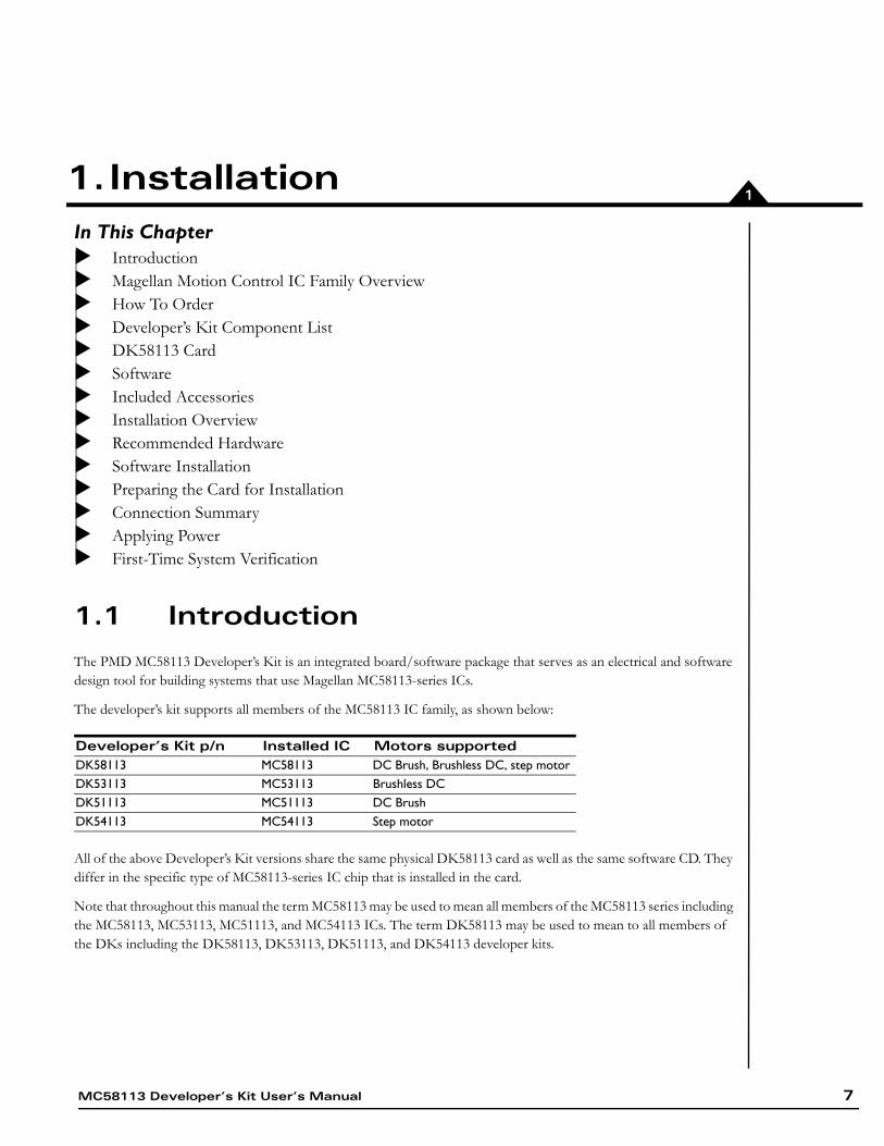
The PMD MC58113 Developer’s Kit is an integrated board/software package that serves as an electrical and software design tool for building systems that use Magellan MC58113-series ICs.
The developer’s kit supports all members of the MC58113 IC family, as shown below:
All of the above Developer’s Kit versions share the same physical DK58113 card as well as the same software CD. They differ in the specific type of MC58113-series IC chip that is installed in the card.
Note that throughout this manual the term MC58113 may be used to mean all members of the MC58113 series including the MC58113, MC53113, MC51113, and MC54113 ICs. The term DK58113 may be used to mean to all members of the DKs including the DK58113, DK53113, DK51113, and DK54113 developer kits.
Developer’s Kit p/n Installed IC Motors supportedDK58113 MC58113 DC Brush, Brushless DC, step motorDK53113 MC53113 Brushless DCDK51113 MC51113 DC BrushDK54113 MC54113 Step motor
MC58113 Developer’s Kit User’s Manual 7

Installation1
1.2 Magellan Motion Control IC Family Overview
The following table presents a feature summary of the products in the Magellan Motion Control IC product family:
M C 5 8 0 0 0 S e r i e s( E x c e p t M C 5 8 11 3 )
M C 5 5 0 0 0 S e r i e s M C 5 8 11 3 S e r i e s
# of axes 1, 2, 3, 4 1, 2, 3, 4 1+ (primary & aux channel encoder input)
Motor types supported DC brush, brushless DC, step motor
Step motor DC brush, brushless DC, step motor
Output format SPI Atlas, PWM, DAC, Pulse & direction
Pulse & direction SPI Atlas, PWM, DAC, Pulse & direction
Parallel host communication Serial host communication CAN 2.0B host communication SPI host communication Incremental encoder input Parallel word device input Index & Home signals Position capture Directional limit switches PWM output Parallel DAC output SPI Atlas interface SPI DAC output Pulse & direction output Digital current control (with Atlas) Field oriented control (with Atlas) Under/overvoltage sense (with Atlas)
12T Current foldback (with Atlas) DC Bus shunt resistor control Overtemperature sense (with Atlas) Short circuit sense (with Atlas) Ground fault detection (with Atlas)Trapezoidal profiling Velocity profiling S-curve profiling Electronic gearing On-the-fly changes PID position servo loop Dual biquad filters Dual encoder loop (multi-axis
configurations only)
Programmable derivative sampling time
Feedforward (accel & vel) Data trace/diagnostics Motion error detection (with encoder) Axis settled indicator (with encoder) Analog input Programmable bit output Software-invertible signals User-defined I/O Internal Trace Buffer External RAM support Multi-chip synchronization
8 MC58113 Developer’s Kit User’s Manual
Installation 1
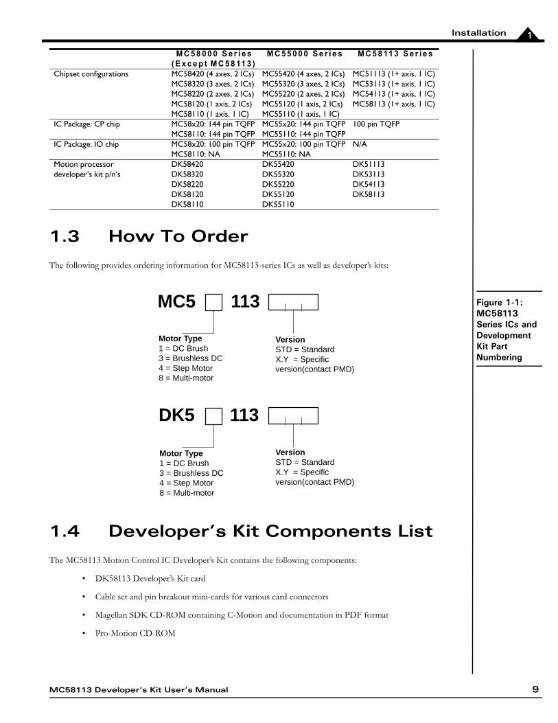
1.3 How To Order
The following provides ordering information for MC58113-series ICs as well as developer’s kits:
Figure 1-1:MC58113 Series ICs and Development Kit Part Numbering
1.4 Developer’s Kit Components List
The MC58113 Motion Control IC Developer’s Kit contains the following components:
• DK58113 Developer’s Kit card
• Cable set and pin breakout mini-cards for various card connectors
• Magellan SDK CD-ROM containing C-Motion and documentation in PDF format
• Pro-Motion CD-ROM
Chipset configurations MC58420 (4 axes, 2 ICs)MC58320 (3 axes, 2 ICs)MC58220 (2 axes, 2 ICs)MC58120 (1 axis, 2 ICs)MC58110 (1 axis, 1 IC)
MC55420 (4 axes, 2 ICs)MC55320 (3 axes, 2 ICs)MC55220 (2 axes, 2 ICs)MC55120 (1 axis, 2 ICs)MC55110 (1 axis, 1 IC)
MC51113 (1+ axis, 1 IC)MC53113 (1+ axis, 1 IC)MC54113 (1+ axis, 1 IC)MC58113 (1+ axis, 1 IC)
IC Package: CP chip MC58x20: 144 pin TQFPMC58110: 144 pin TQFP
MC55x20: 144 pin TQFPMC55110: 144 pin TQFP
100 pin TQFP
IC Package: IO chip MC58x20: 100 pin TQFPMC58110: NA
MC55x20: 100 pin TQFPMC55110: NA
N/A
Motion processor developer’s kit p/n’s
DK58420 DK58320DK58220DK58120DK58110
DK55420DK55320DK55220DK55120DK55110
DK51113DK53113DK54113DK58113
M C 5 8 0 0 0 S e r i e s( E x c e p t M C 5 8 11 3 )
M C 5 5 0 0 0 S e r i e s M C 5 8 11 3 S e r i e s
MC58113 Developer’s Kit User’s Manual 9
Installation1
Documentation:
• MC58113 Developer’s Kit Manual
• Magellan Motion Control IC User’s Guide
• Magellan Motion Control IC Programmer’s Command Reference
• MC58113 Electrical Specifications
• Pro-Motion User's Guide
If any of these components are missing, please contact your PMD representative.
1.5 DK58113 Card
The heart of the MC58113 Motion Control IC Developer’s Kit is the DK58113 printed circuit card that contains interface and amplifier circutiry to allow various features of the MC58113-family ICs to be accessed. Here is a summary of the features provided by the DK58113 card:
• Supports step, DC Brush, and Brushless DC motors
• IC socket allows MC58113s to be swapped out for testing or user configuration storage
• High performance on-card amplifier with current feedback supports all motor types
• Interfaces to external Atlas, user-designed, or pulse & direction amplifier
• RS-232, RS-485, CANbus, and SPI (Serial Peripheral Interface) host communications
• Single DC-voltage supply
• Primary and auxiliary axis quadrature signal input with Index and Home capture
• Hall sensor, Home, limits, AxisIn and AxisOut signals
• Support for overtemperature, overcurrent, over and undervoltage sense
• High current external shunt resistor support
• Pulse & Direction signals with AtRest for use with external step motor amplifiers
• Compact 3.3" x 4.7" standalone form factor (8.4 cm x 11.9 cm)
1.6 Software
Three major software packages are provided with the DK58113:
Pro-Motion®, an interactive Windows-based exerciser & software development tool
C-Motion®, a C-language library that allows you to create motion applications using the C programming language
VB-Motion®, DLLs and source code that let you create motion applications using .net languages, for example Visual Basic and C#
Here is more information on each of these software packages:
10 MC58113 Developer’s Kit User’s Manual

Installation 1
1.6.1 Pro-Motion
Pro-Motion is a sophisticated, easy-to-use exerciser program which allows all MC58113 parameters to be set and/or viewed, and allows all features to be exercised. Pro-Motion features include:
• Motion oscilloscope graphically displays processor parameters in real-time
• AxisWizard to automate axis setup and configuration
• Position loop and current loop auto-tuning
• Project window for accessing motion resources and connections
• Ability to save and load settings
• Distance, time, and electrical units conversion
• Frequency sweep and bode plot analysis tools
• Motor-specific parameter setup
• Axis shuttle performs continuous back and forth motion between two positions
• C-Motion Engine monitor/debug window
• C-Motion Engine user application code download
Pro-Motion is described in the Pro-Motion User’s Guide.
1.6.2 C-Motion
C-Motion provides a convenient set of callable routines comprising the code required for controlling the Magellan Motion Control IC, whether running on a separate host computer such as a PC, or running on a C-Motion Engine. C-Motion includes the following features:
• Magellan axis virtualization
• Ability to communicate to multiple PMD motion cards or modules
• Ability to communicate via PCIbus, PC/104bus, serial, CANbus, Ethernet, or SPI (Serial Peripheral Interface)
• Provided as source code, allowing easy compilation & porting onto various run-time environments including PC, microprocessor, embedded card, or C-Motion Engine
• Can be easily linked to any C/C++ application
C-Motion is described in the Magellan Motion Control IC Programmer’s Command Reference.
1.6.3 Language Support
A complete set of methods and properties is provided for developing applications in Visual Basic and C# using a dynamically loaded library (DLL) containing PMD library software. The DLL may also be used from any language capable of calling C language DLL procedures, but no special software support is provided.
Includes the following features:
• Magellan axis virtualization
• Ability to communicate to multiple PMD motion cards or modules
MC58113 Developer’s Kit User’s Manual 11

Installation1
• Ability to communicate via PCI bus, serial, CANbus, or Ethernet
• Provided as a single DLL and Visual Basic .NET source code for easy porting onto various PC environments
VB Motion is documented in the PMD Resource Access Protocol Progammer’s Reference.
1.7 Included Accessories
The DK58113 includes various accessories that you may find useful:
If for whatever reason you need to order more of these accessories, refer to the part numbers above and contact your PMD representative.
1.8 Installation Overview
1 Before using the card, the software must be installed. See Section 1.10, “Software Installation,” on page 13 for instructions on installing the software.
2 For a normal installation of the DK58113 card you will need to configure the card. See Section 1.11, “Preparing the Card for Installation,” on page 14 for a description of configuring the card.
3 Next, connect the system’s motors, encoder(s), and sensors to operate the motion hardware. See Section 1.12, “Connection Summary,” on page 16 for a description of the available connections and options for the DK58113 card.
4 Connect the DK58113 card to the host PC via a Serial cable. This is described in Section 1.12.4, “Communication Connections,” on page 19.
5 Once this hardware configuration is complete, the final step to finish the installation is to perform a functional test of the finished system. See Section 1.14, “First-Time System Verification,” on page 19 for a description of this procedure.
Once these steps have been accomplished, the installation is complete, and the card is ready for operation.
Component PMD Part Number
Description
Cable-1007-01 Serial cable. This cable connects to the DK58113’s DB-9 serial port and provides a connection to a PC serial port or USB to serial converter.
Cable-4705-KIT-01.R CANbus connector and terminator. This cable connects to the card’s CANbus connector and has RJ45 connectors on both ends.
MC-HW-05 DB-15 breakout interconnect. This module provides convenient jack-screw type terminators for the 15-pin axis connectors. Two units included.
Adapt-USB232-01.R This adapter provides USB to serial conversion. It is useful for connecting to the DB-9 serial port from a USB port.
CONN-0122-11 Power & shunt connector jack screw terminals. This two-pin plug provides convenient jack-screw-type terminals for the high current terminal block header power & shunt resistor connectors. Two units included
CONN-0121-11 Motor connector jackscrew terminals. This five-pin plug provides convenient jack-screw-type terminals for the high current terminal block header motor connector.
12 MC58113 Developer’s Kit User’s Manual

Installation 1
1.9 Recommended Hardware
To install a DK58113 card the following hardware is recommended. Note that this list assumes that the on-card amplifier will be used. For installation of a user-provided off-card amplifier, see Section 2.6, “Connecting to a Remote Amplifier,” on page 36.
• Intel (or compatible) processor, Pentium or better, 300MB of available disk space, 256 MB of available RAM, and a CD-ROM drive. The supported PC operating systems are Windows XP/Vista/Windows 7
• One step, DC brush, or brushless DC motor.
This motor may or may not provide encoder position feedback signals, depending on the type of motor being used. Encoder feedback is a requirement for DC brush motors, and is normally used with brushless DC motors (although not required because Hall sensors can be used for the position feedback). For step motors, encoders are an option.
• Cables as required to connect to the motor and associated motion hardware such as feedback signals, home sensor, and limit switches. If the auxiliary axis is being used, then additional cables will be used to connect to this second encoder.
• Power supply, power cable, and communication cables. The DK58113 card requires only a single voltage supply. The card logic and other circuitry is powered from this input voltage using an on-card DC to DC converter. Although the DK58113 supports serial, CANbus and SPI communications, for first-time installation you will use the card’s serial port.
1.10 Software Installation
Two CD-ROMs comprise the software distribution for the MC58113 developer’s kit. All software applications are designed to work with Windows XP, Vista, or Windows 7.
• Pro-Motion: The Pro-Motion disk is located in its own Pro-Motion box, and contains the software associated with the Pro-Motion Optimized Motion System Development software.
• Magellan SDK: This disk is contains the C-Motion source libraries, and VB-Motion Libraries.
To install the software:
1 Insert the Pro-Motion disk into the CD-ROM drive of your computer.
• If autorun is enabled, the installation process will begin when the CD-ROM is inserted.
• If autorun is not enabled, go to the next step.
2 On the Start menu, click Run.
3 In the Open text box, type D:\setup.exe.
where D:is the drive letter of your computer’s CD-ROM drive.
4 Follow the on-screen prompts to complete the installation process.
Once installation of Pro-Motion is complete, insert the Magellan SDK disk, and follow the same procedure above as for Pro-Motion installation.
Upon completion of the installation process for Pro-Motion and SDK, the following components will be installed:
• Pro-Motion–an application for communicating to, and exercising the motion processor. Refer to the Pro- Motion User’s Guide for operating instructions.
MC58113 Developer’s Kit User’s Manual 13
Installation1
• C-Motion–source code which may be used for developing motion applications in C/C++ based on the Magellan Motion Control IC.
• DLLs and example source code which may be used for developing motion applications in Visual Basic or C# based on the MC58113.
• PDF versions of the MC58113 Developer’s Kit User’s Manual, MC58113 Electrical Specifications, Magellan Motion Control IC Programmer’s Command Reference, and Magellan Motion Control IC User’s Guide. Adobe Acrobat Reader is required for viewing these files. If the Adobe Acrobat Reader is not installed on your computer, it may be freely downloaded from http://www..adobe.com.
1.11 Preparing the Card for Installation
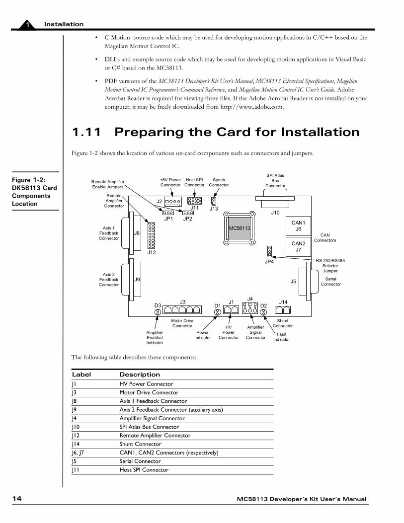
Figure 1-2 shows the location of various on-card components such as connectors and jumpers.
Figure 1-2:DK58113 Card Components Location
The following table describes these components:
Label DescriptionJ1 HV Power ConnectorJ3 Motor Drive ConnectorJ8 Axis 1 Feedback ConnectorJ9 Axis 2 Feedback Connector (auxiliary axis)J4 Amplifier Signal ConnectorJ10 SPI Atlas Bus ConnectorJ12 Remote Amplifier ConnectorJ14 Shunt ConnectorJ6, J7 CAN1, CAN2 Connectors (respectively)J5 Serial ConnectorJ11 Host SPI Connector
CAN2J7
CAN1J6
CAN Connectors
J1J3
HVPower
Connector
Motor Drive Connector
J14
Shunt Connector
J5 Serial Connector
J11
Host SPI Connector
J13
Synch Connector
J10
SPI AtlasBus
Connector
Axis 1FeedbackConnector
Axis 2FeedbackConnector
J2
+5V Power Connector
J12
RemoteAmplifier
Connector
JP1 JP2
Remote AmplifierEnable Jumpers
D1 D2D3J4
AmplifierSignal
Connector
JP4 RS-232/RS485Selector Jumper
AmplifierEnabledIndicator
PowerIndicator
FaultIndicator
J9
J8MC58113
14 MC58113 Developer’s Kit User’s Manual
Installation 1
There are no jumper changes that need to be made to the card. The DK58113 comes factory-configured to be compatible with the ‘first time installation’ instructions contained in this chapter.
However, for reference the table below shows the available jumper settings of the DK58113 card:
1.11.1 Enabling the Card
The MC58113 requires an active Enable signal to operate. To accomplish this the Amplifier Signal Connector (J4) is used. Connect terminal #1 of J4 to terminal #3 of J4 using a short wire. J4 provides convenient push-type connections, so no other hardware is needed to make this connection.
For reference the following table provides the pinouts of the J4 terminal block connector:
J13 Synch ConnectorJ2 +5V Power ConnectorD1, D2, D3 Power, fault, and amplifier enabled LED indicators
(respectively)JP1, JP2 Remote amplifier enable jumpersJP4 RS-232/RS-485 selector jumper
Jumper IDFactory Default Setting Setting &Description
JP1, JP2 1-2 (on-card amplifier) 1-2 Installing jumpers at 1-2 for JP1 and JP2 configures the DK58113 for operation of the on-card amplifier.
2-3 Installing jumpers at 2-3 for JP1 and JP2 disables the on-card amplifier, and configures the DK58113 for operation with a user-designed amplifier via the J12 Remote Amplifier Connector, or with an Atlas DK amplifier via the J10 connector.
JP4 1-2 (RS-232) 1-2 Installing a jumper at 1-2 for JP4 configures the DK58113 for RS-232 serial operation.
2-3 Installing a jumper at 2-3 for JP4 configures the DK58113 for RS-485 serial operation.
Setting & Description Pin # DescriptionEnable 1 Enable input. Must be tied low (GND) to enable
the MC58113 for full operation.FaultOut 2 Programmable FaultOut signal output.GND 3 Digital ground
Label Description
MC58113 Developer’s Kit User’s Manual 15
Installation1
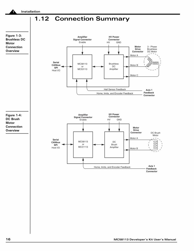
1.12 Connection Summary
Figure 1-3:Brushless DC Motor Connection Overview
Figure 1-4:DC Brush Motor Connection Overview
Motor A
Motor B
Motor C
Hall Sensor Feedback
BrushlessDC
Amplifier
3 - PhaseBrushlessDC Motor
MC58113or
MC53113
SerialCANbus
SPIHost I/O
Home, limits, and Encoder Feedback
Axis 1Feedback Connector
MotorDrive
Connector
HV GND
AmplifierSignal Connector
Enable
HV PowerConnector
Home, limits, and Encoder Feedback Axis 1Feedback Connector
DCBrush
Amplifier
DC BrushMotor
MC58113or
MC51113
MotorDrive
Connector
AmplifierSignal Connector
Enable HV GND
HV Power Connector
Motor A
Motor B
SerialCANbus
SPIHost I/O
16 MC58113 Developer’s Kit User’s Manual
Installation 1
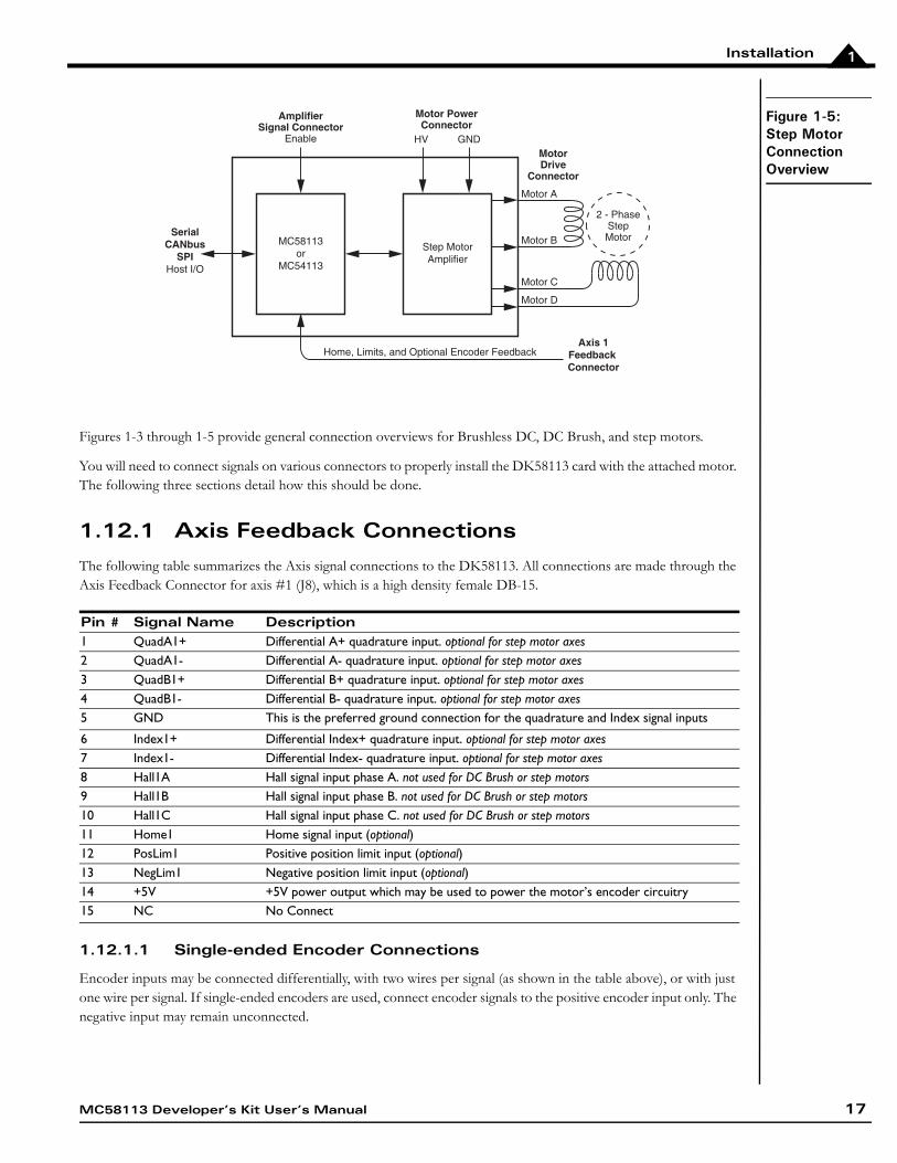
Figure 1-5:Step Motor Connection Overview
Figures 1-3 through 1-5 provide general connection overviews for Brushless DC, DC Brush, and step motors.
You will need to connect signals on various connectors to properly install the DK58113 card with the attached motor. The following three sections detail how this should be done.
1.12.1 Axis Feedback Connections
The following table summarizes the Axis signal connections to the DK58113. All connections are made through the Axis Feedback Connector for axis #1 (J8), which is a high density female DB-15.
1.12.1.1 Single-ended Encoder Connections
Encoder inputs may be connected differentially, with two wires per signal (as shown in the table above), or with just one wire per signal. If single-ended encoders are used, connect encoder signals to the positive encoder input only. The negative input may remain unconnected.
Pin # Signal Name Description1 QuadA1+ Differential A+ quadrature input. optional for step motor axes2 QuadA1- Differential A- quadrature input. optional for step motor axes3 QuadB1+ Differential B+ quadrature input. optional for step motor axes4 QuadB1- Differential B- quadrature input. optional for step motor axes5 GND This is the preferred ground connection for the quadrature and Index signal inputs
6 Index1+ Differential Index+ quadrature input. optional for step motor axes7 Index1- Differential Index- quadrature input. optional for step motor axes8 Hall1A Hall signal input phase A. not used for DC Brush or step motors9 Hall1B Hall signal input phase B. not used for DC Brush or step motors10 Hall1C Hall signal input phase C. not used for DC Brush or step motors11 Home1 Home signal input (optional)12 PosLim1 Positive position limit input (optional)13 NegLim1 Negative position limit input (optional)14 +5V +5V power output which may be used to power the motor’s encoder circuitry15 NC No Connect
Home, Limits, and Optional Encoder Feedback
Step MotorAmplifier
2 - PhaseStepMotorMC58113
orMC54113
Axis 1Feedback Connector
MotorDrive
Connector
Motor PowerConnector
Motor C
Motor D
Motor A
Motor B
HV GND
AmplifierSignal Connector
Enable
SerialCANbus
SPIHost I/O
MC58113 Developer’s Kit User’s Manual 17
Installation1
1.12.1.2 Auxiliary Encoder Input
J9 is the feedback connector for axis #2, which is the auxiliary axis for the MC58113 IC. This axis provides an additional encoder datastream for use in the MC58113’s dual loop control mode or with electronic gear profile mode. In addition various other signals are input via this connector.
For this 'getting started' installation of the DK58113 the auxiliary encoder inputs will not be used. For detailed information on the J9 connector and related electrical functions see Section 3.2.3, “Axis Feedback Connectors (J8, J9),” on page 45
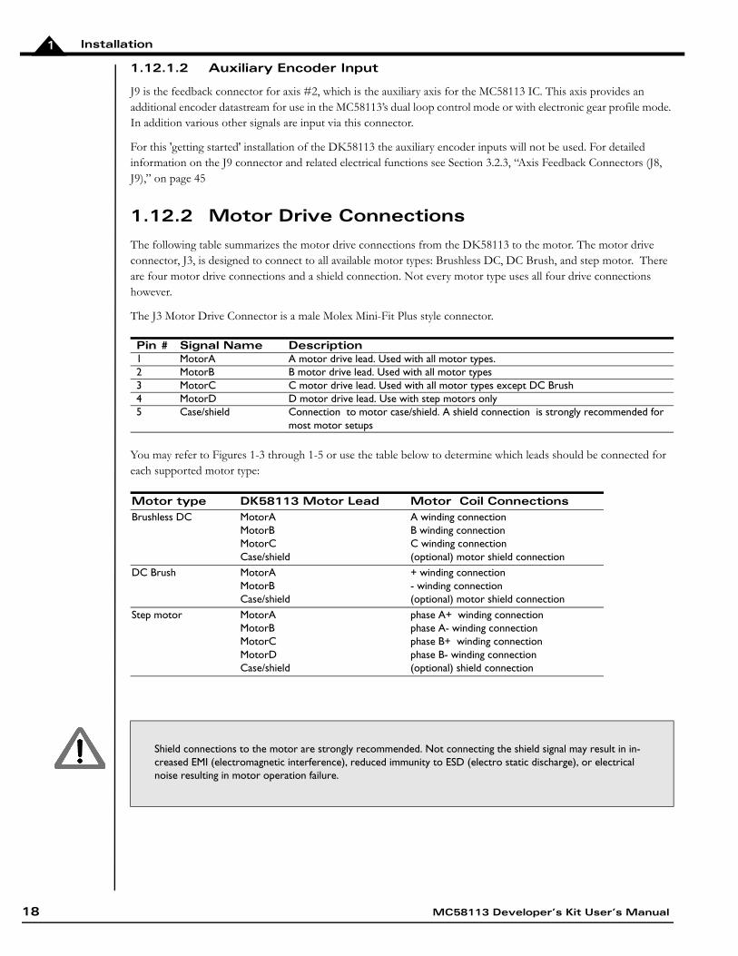
1.12.2 Motor Drive Connections
The following table summarizes the motor drive connections from the DK58113 to the motor. The motor drive connector, J3, is designed to connect to all available motor types: Brushless DC, DC Brush, and step motor. There are four motor drive connections and a shield connection. Not every motor type uses all four drive connections however.
The J3 Motor Drive Connector is a male Molex Mini-Fit Plus style connector.
You may refer to Figures 1-3 through 1-5 or use the table below to determine which leads should be connected for each supported motor type:
Pin # Signal Name Description1 MotorA A motor drive lead. Used with all motor types.2 MotorB B motor drive lead. Used with all motor types3 MotorC C motor drive lead. Used with all motor types except DC Brush4 MotorD D motor drive lead. Use with step motors only5 Case/shield Connection to motor case/shield. A shield connection is strongly recommended for
most motor setups
Motor type DK58113 Motor Lead Motor Coil ConnectionsBrushless DC MotorA
MotorBMotorCCase/shield
A winding connectionB winding connectionC winding connection(optional) motor shield connection
DC Brush MotorAMotorBCase/shield
+ winding connection- winding connection(optional) motor shield connection
Step motor MotorAMotorBMotorCMotorDCase/shield
phase A+ winding connectionphase A- winding connectionphase B+ winding connectionphase B- winding connection(optional) shield connection
Shield connections to the motor are strongly recommended. Not connecting the shield signal may result in in-creased EMI (electromagnetic interference), reduced immunity to ESD (electro static discharge), or electrical noise resulting in motor operation failure.
18 MC58113 Developer’s Kit User’s Manual
Installation 1
1.12.3 Motor Power Connections
The following table summarizes the motor power connections from the DK58113 to your power supply. This HV connection is also the power connection from which the card logic power is derived using an on-board DC-DC converter.
All connections are made through the Motor Power Connector, which is a Phoenix Contact 2-circuit terminal block Connector.
The HV voltage should be the voltage at which the motor will be driven and must be in the range of 12V - 56V.
1.12.4 Communication Connections
While the DK58113 card can communicate using CANbus, SPI (Serial Peripheral Interface), and one of two serial modes (RS-232 and RS-485), in this first-time installation we will set up the card for serial RS-232 communications. To set up the card for operation in other communication modes, see Chapter 2, “Operation” and the Pro-Motion User’s Guide.
A serial port accessory cable is included with the DK58113. This serial cable (PMD p/n Cable-1007-01) should be connected to the DK58113 card’s J5 Serial Connector, while the opposite end of the serial cable should be connected to your computer’s 9 pin serial port. If your computer does not have a dedicated serial port, the included USB to serial converter should be used.
1.13 Applying Power
Once you have made your motion hardware, communication, and power connections, hardware installation is complete and the card is ready for operation. When power is applied, the DK58113’s green power LED should light. This LED is locatable using Figure 1-2. If the LED does not light, recheck connections.
After power up no motor output will be applied. Therefore the motors should remain stationary. If the motors move or jump, power down the card and check the motor and encoder connections. If anomalous behavior is still observed, call PMD or your PMD representative for assistance.
1.14 First-Time System Verification
The first time system verification procedure summarized below has two overall goals. The first is to connect the DK58113 card with the PC that is being used so that they are communicating properly, and the second is to initialize the axis and bring it under stable control capable of making trajectory moves. While there are many additional capabilities that Pro-Motion and the DK58113 card provide, these steps will create a foundation for further successful exploration and development.
Here is a summary of the steps that will be used during first time system verification. Each of these steps will be described below in a separate manual section.
1 Initiate Pro-Motion and establish communication between the PC and the card using the serial communications link.
Pin # Signal Name Description1 HV Positive motor voltage power2 GND Motor voltage power ground
MC58113 Developer’s Kit User’s Manual 19
Installation1
2 Run Pro-Motion’s Axis wizard to initialize parameters such as encoder direction and safe servo parameters (if using a servo motor). Important! In addition to application specific parameters you will need to enter various on-card amplifier-related parameters during Axis Wizard setup to safely operate with the on-card amplifier. Refer to Section 3.6, “DK58113 On-Card Amplifier Quick Reference,” on page 52 of this manual for a list of these required settings.
3 Execute a simple trajectory profile on each axis demonstrating that it is operating correctly and under stable control.
During this first time system setup you may find it useful to refer to other PMD manuals including the Pro-Motion User’s Guide for complete information on the Pro-Motion application. You may also want to refer to the Magellan Motion Control IC User’s Guide to familiarize yourself with operation of the MC58113, or the MC58113 Electrical Specifications.
1.14.1 Establishing Serial Communications
To establish serial communications:
1 Make sure the MC58113 card is powered and connected to the PC via its serial port.
2 Launch the Pro-Motion application.
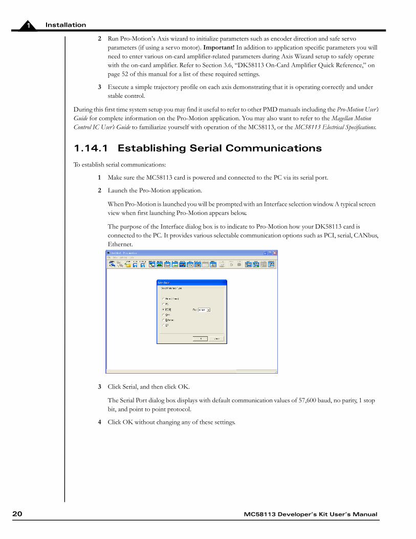
When Pro-Motion is launched you will be prompted with an Interface selection window. A typical screen view when first launching Pro-Motion appears below..
The purpose of the Interface dialog box is to indicate to Pro-Motion how your DK58113 card is connected to the PC. It provides various selectable communication options such as PCI, serial, CANbus, Ethernet.
3 Click Serial, and then click OK.
The Serial Port dialog box displays with default communication values of 57,600 baud, no parity, 1 stop bit, and point to point protocol.
4 Click OK without changing any of these settings.
20 MC58113 Developer’s Kit User’s Manual
Installation 1
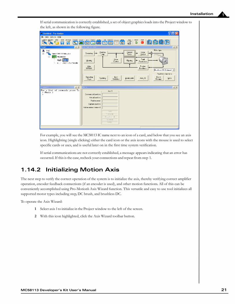
If serial communication is correctly established, a set of object graphics loads into the Project window to the left, as shown in the following figure.
For example, you will see the MC58113 IC name next to an icon of a card, and below that you see an axis icon. Highlighting (single clicking) either the card icon or the axis icons with the mouse is used to select specific cards or axes, and is useful later on in the first time system verification.
If serial communications are not correctly established, a message appears indicating that an error has occurred. If this is the case, recheck your connections and repeat from step 1.
1.14.2 Initializing Motion Axis
The next step to verify the correct operation of the system is to initialize the axis, thereby verifying correct amplifier operation, encoder feedback connections (if an encoder is used), and other motion functions. All of this can be conveniently accomplished using Pro-Motion’s Axis Wizard function. This versatile and easy to use tool initializes all supported motor types including step, DC brush, and brushless DC.
To operate the Axis Wizard:
1 Select axis 1 to initialize in the Project window to the left of the screen.
2 With this icon highlighted, click the Axis Wizard toolbar button.
MC58113 Developer’s Kit User’s Manual 21
Installation1
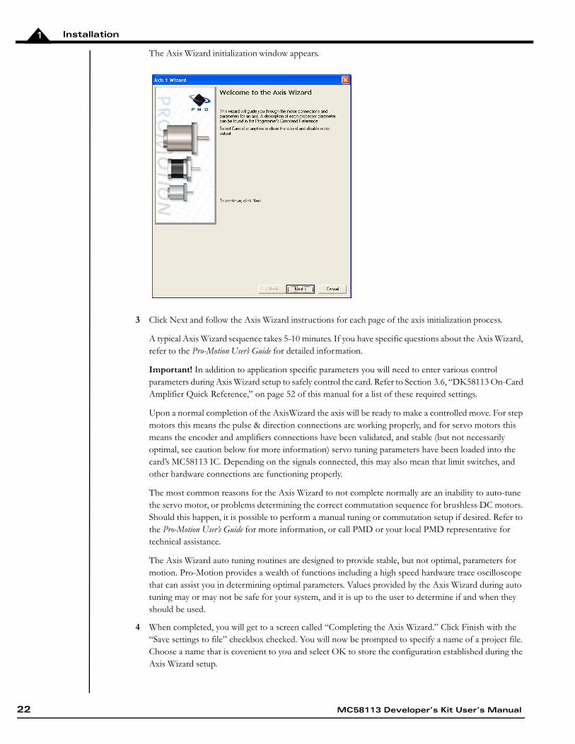
The Axis Wizard initialization window appears.
3 Click Next and follow the Axis Wizard instructions for each page of the axis initialization process.
A typical Axis Wizard sequence takes 5-10 minutes. If you have specific questions about the Axis Wizard, refer to the Pro-Motion User’s Guide for detailed information.
Important! In addition to application specific parameters you will need to enter various control parameters during Axis Wizard setup to safely control the card. Refer to Section 3.6, “DK58113 On-Card Amplifier Quick Reference,” on page 52 of this manual for a list of these required settings.
Upon a normal completion of the AxisWizard the axis will be ready to make a controlled move. For step motors this means the pulse & direction connections are working properly, and for servo motors this means the encoder and amplifiers connections have been validated, and stable (but not necessarily optimal, see caution below for more information) servo tuning parameters have been loaded into the card’s MC58113 IC. Depending on the signals connected, this may also mean that limit switches, and other hardware connections are functioning properly.
The most common reasons for the Axis Wizard to not complete normally are an inability to auto-tune the servo motor, or problems determining the correct commutation sequence for brushless DC motors. Should this happen, it is possible to perform a manual tuning or commutation setup if desired. Refer to the Pro-Motion User’s Guide for more information, or call PMD or your local PMD representative for technical assistance.
The Axis Wizard auto tuning routines are designed to provide stable, but not optimal, parameters for motion. Pro-Motion provides a wealth of functions including a high speed hardware trace oscilloscope that can assist you in determining optimal parameters. Values provided by the Axis Wizard during auto tuning may or may not be safe for your system, and it is up to the user to determine if and when they should be used.
4 When completed, you will get to a screen called “Completing the Axis Wizard.” Click Finish with the “Save settings to file” checkbox checked. You will now be prompted to specify a name of a project file. Choose a name that is covenient to you and select OK to store the configuration established during the Axis Wizard setup.
22 MC58113 Developer’s Kit User’s Manual
Installation 1
1.14.3 Performing a Simple Trajectory Move
The last step in first time system verification is to perform a simple move for the axis. To perform a simple move:
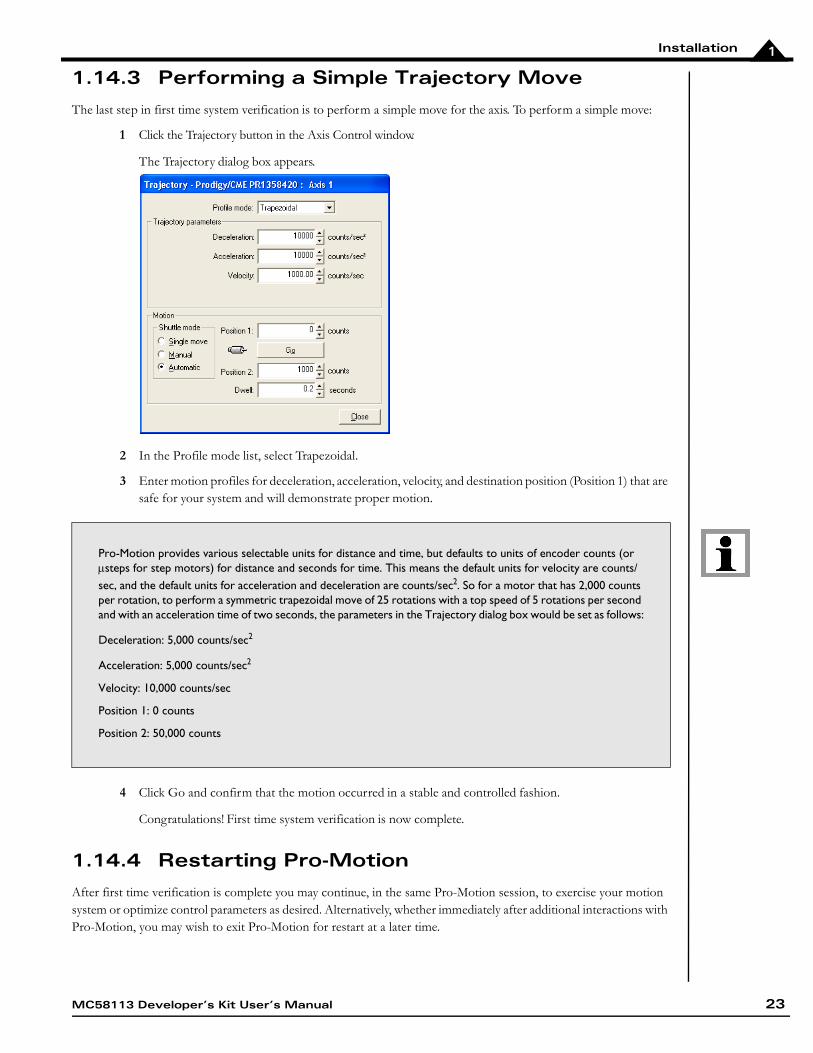
1 Click the Trajectory button in the Axis Control window.
The Trajectory dialog box appears.
2 In the Profile mode list, select Trapezoidal.
3 Enter motion profiles for deceleration, acceleration, velocity, and destination position (Position 1) that are safe for your system and will demonstrate proper motion.
4 Click Go and confirm that the motion occurred in a stable and controlled fashion.
Congratulations! First time system verification is now complete.
1.14.4 Restarting Pro-Motion
After first time verification is complete you may continue, in the same Pro-Motion session, to exercise your motion system or optimize control parameters as desired. Alternatively, whether immediately after additional interactions with Pro-Motion, you may wish to exit Pro-Motion for restart at a later time.
Pro-Motion provides various selectable units for distance and time, but defaults to units of encoder counts (or steps for step motors) for distance and seconds for time. This means the default units for velocity are counts/ sec, and the default units for acceleration and deceleration are counts/sec2. So for a motor that has 2,000 counts per rotation, to perform a symmetric trapezoidal move of 25 rotations with a top speed of 5 rotations per second and with an acceleration time of two seconds, the parameters in the Trajectory dialog box would be set as follows:
Deceleration: 5,000 counts/sec2
Acceleration: 5,000 counts/sec2
Velocity: 10,000 counts/sec
Position 1: 0 counts
Position 2: 50,000 counts
MC58113 Developer’s Kit User’s Manual 23
Installation1
If you have changed additional control parameters and would like to save these parameters use File and Save Project to update the stored configuration file. At this time you may update your existing project file or provide a new one.
When restarting Pro-Motion it is important that you restore the configuration that you have saved, particularly the on-card amplifier limits and scale factors established during Axis Wizard setup. Do this by selecting File and Open Project, selecting the correct file previously stored.
Operation of the DK58113 without proper safety settings established during Axis Wizard operation may harm the DK58113 card or the application hardware. To avoid this be sure to restore saved control settings using the File/Open Project menu item before operating the DK58113 card.
24 MC58113 Developer’s Kit User’s Manual
MC58113 Developer’s Kit User’s Manual 25
22.OperationIn This ChapterDK58113 Block Diagram Communication PortsSwitching Motor AmplifierDrive Protection and Control SignalsDC BusConnecting to a Remote AmplifierConnecting to an Atlas AmplifierMotor Feedback SignalsEnable and FaultOut SignalsMulti-card Synchronization
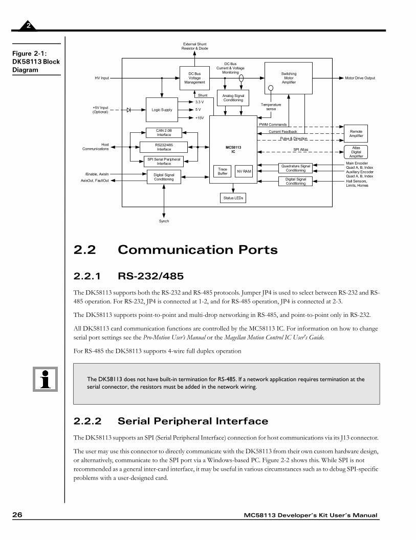
2.1 DK58113 Block Diagram
The MC58113 Developer’s Kit card (DK58113) provides a complete functioning MC58113-series IC exerciser and development system. It directly interfaces to a host computer using serial, CANBus, or SPI communication, and to all power and feedback signals required to drive a DC Brush, Brushless DC, or step motor.
The DK58113 incorporates several major subsystems including the MC58113-series IC itself, communications interface circuitry, a high performance MOSFET-based motor amplifier, a DC Bus conditioning system, and various other circuitry.
The following sections describe these major sections of the DK58113 card. For a complete description of the MC58113 IC, see the Magellan Motion Control IC User's Guide, MC58113 Electrical Specifications, and the Magellan Motion Control IC Programmers Command Reference.
26 MC58113 Developer’s Kit User’s Manual
2
Figure 2-1:DK58113 Block Diagram
2.2 Communication Ports
2.2.1 RS-232/485
The DK58113 supports both the RS-232 and RS-485 protocols. Jumper JP4 is used to select between RS-232 and RS-485 operation. For RS-232, JP4 is connected at 1-2, and for RS-485 operation, JP4 is connected at 2-3.
The DK58113 supports point-to-point and multi-drop networking in RS-485, and point-to-point only in RS-232.
All DK58113 card communication functions are controlled by the MC58113 IC. For information on how to change serial port settings see the Pro-Motion User’s Manual or the Magellan Motion Control IC User's Guide.
For RS-485 the DK58113 supports 4-wire full duplex operation
2.2.2 Serial Peripheral Interface
The DK58113 supports an SPI (Serial Peripheral Interface) connection for host communications via its J13 connector.
The user may use this connector to directly communicate with the DK58113 from their own custom hardware design, or alternatively, communicate to the SPI port via a Windows-based PC. Figure 2-2 shows this. While SPI is not recommended as a general inter-card interface, it may be useful in various circumstances such as to debug SPI-specific problems with a user-designed card.
The DK58113 does not have built-in termination for RS-485. If a network application requires termination at the serial connector, the resistors must be added in the network wiring.
Auxillary EncoderQuad A, B, Index
MC58113IC
SwitchingMotor
Amplifier
DC BusVoltage
Management
Analog Signal Conditioning
Quadrature SignalConditioning
Digital SignalConditioning
Digital SignalConditioning
RS232/485Interface
Main EncoderQuad A, B, Index
Hall Sensors, Limits, Homes
Logic Supply
HV Input
+5V Input(Optional)
/Enable, AxisIn
AxisOut, FaultOut
CAN 2.0BInterface
Host Communications
3.3 V
5 V
+15V
Motor Drive Output
PWM Commands
DC BusCurrent & Voltage
Monitoring
Status LEDs
Trace Buffer
SPI Serial PeripheralInterface
Synch
Temperaturesense
RemoteAmplifier
AtlasDigital
Amplifier
SPI Atlas
External Shunt Resistor & Diode
Current Feedback
Shunt
NV RAM
Pulse & Direction
MC58113 Developer’s Kit User’s Manual 27
2
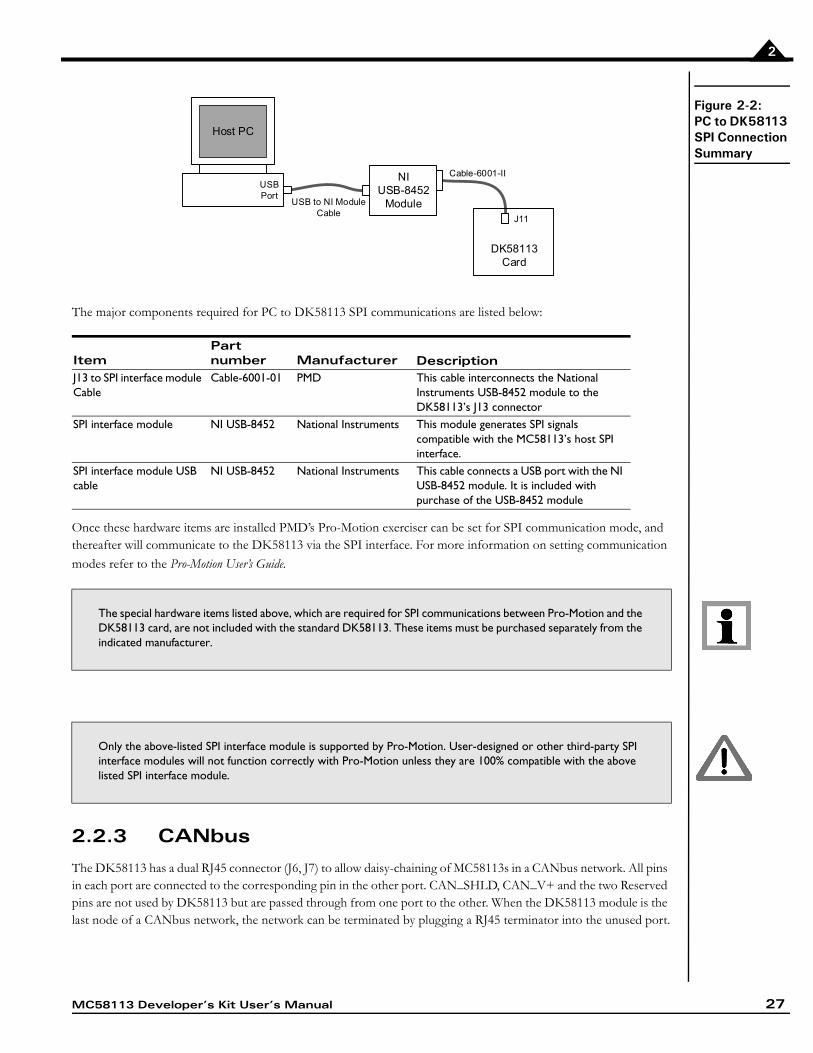
Figure 2-2:PC to DK58113 SPI Connection Summary
The major components required for PC to DK58113 SPI communications are listed below:
Once these hardware items are installed PMD’s Pro-Motion exerciser can be set for SPI communication mode, and thereafter will communicate to the DK58113 via the SPI interface. For more information on setting communication
modes refer to the Pro-Motion User’s Guide.
2.2.3 CANbus
The DK58113 has a dual RJ45 connector (J6, J7) to allow daisy-chaining of MC58113s in a CANbus network. All pins in each port are connected to the corresponding pin in the other port. CAN_SHLD, CAN_V+ and the two Reserved pins are not used by DK58113 but are passed through from one port to the other. When the DK58113 module is the last node of a CANbus network, the network can be terminated by plugging a RJ45 terminator into the unused port.
ItemPart number Manufacturer Description
J13 to SPI interface module Cable
Cable-6001-01 PMD This cable interconnects the National Instruments USB-8452 module to the DK58113’s J13 connector
SPI interface module NI USB-8452 National Instruments This module generates SPI signals compatible with the MC58113’s host SPI interface.
SPI interface module USB cable
NI USB-8452 National Instruments This cable connects a USB port with the NI USB-8452 module. It is included with purchase of the USB-8452 module
The special hardware items listed above, which are required for SPI communications between Pro-Motion and the DK58113 card, are not included with the standard DK58113. These items must be purchased separately from the indicated manufacturer.
Only the above-listed SPI interface module is supported by Pro-Motion. User-designed or other third-party SPI interface modules will not function correctly with Pro-Motion unless they are 100% compatible with the above listed SPI interface module.
Host PC
USBPort
NIUSB-8452
Module
DK58113Card
Cable-6001-II
J11
USB to NI ModuleCable
28 MC58113 Developer’s Kit User’s Manual
2
Standard UTP (unshielded twisted pair) CAT5 Ethernet cabling can be used in most CAN applications. For added noise immunity, shielded cable can be used with the shield routed through the CAN_SLD pins.
2.3 Switching Motor Amplifier
The DK58113 module contains a high-efficiency MOSFET power stage with PWM input control and leg current feedback. A different configuration is used for each motor type:
• Brushless DC motors are driven in a 3-phase bridge configuration consisting of 6 MOSFETs and 3 leg current sensors
• DC Brush motors are driven in an H-Bridge configuration consisting of 4 MOSFETs and 2 leg current sensors
• Step motors are driven with two H-Bridges, one for each phase, for a total of 8 MOSFETs and 4 leg current sensors
To operate the DK58113’s on-card amplifier the JP1 and JP2 jumpers must be installed in the 1-2 position.
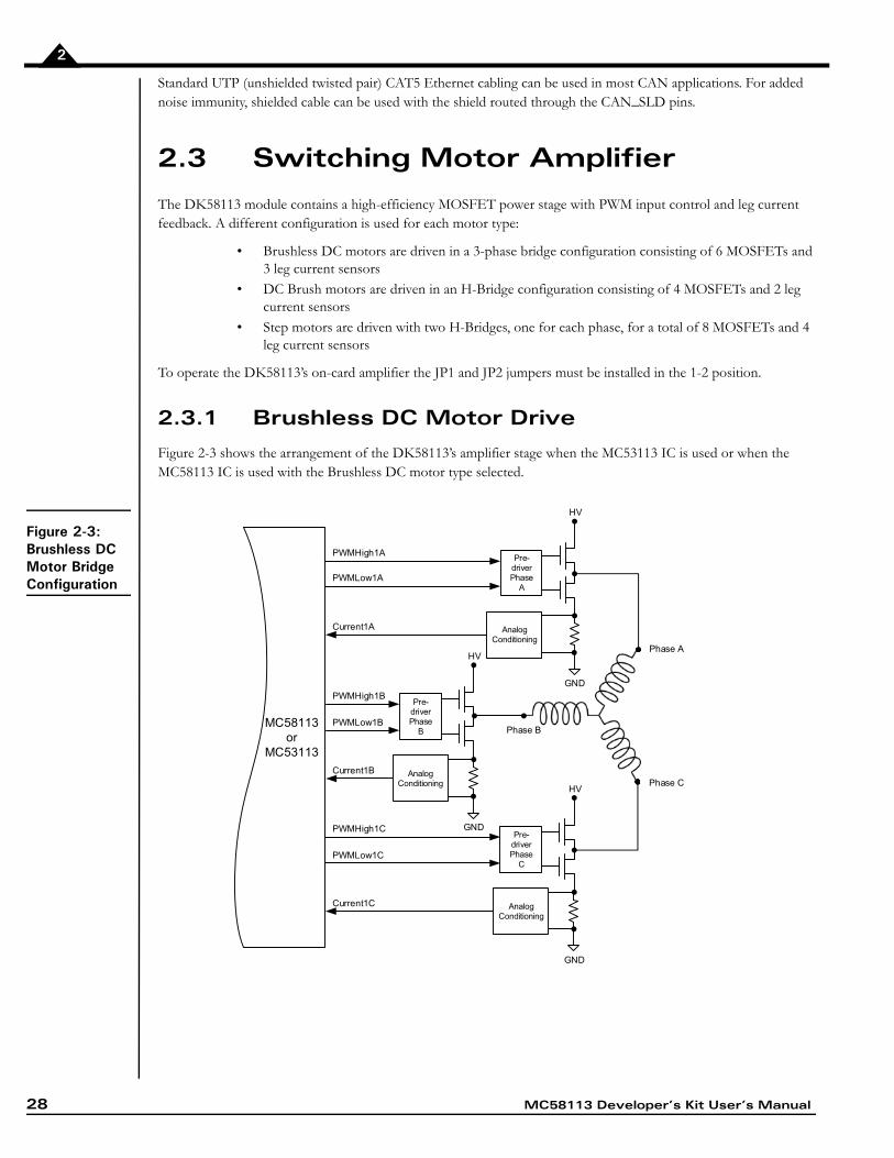
2.3.1 Brushless DC Motor Drive
Figure 2-3 shows the arrangement of the DK58113’s amplifier stage when the MC53113 IC is used or when the MC58113 IC is used with the Brushless DC motor type selected.
Figure 2-3:Brushless DC Motor Bridge Configuration
PWMHigh1B
PWMLow1B
Current1B
PWMHigh1A
PWMLow1A
Current1A
PWMHigh1C
PWMLow1C
Current1C
HV
Pre-driverPhase
A
GND
AnalogConditioning
HV
Pre-driverPhase
B
GND
AnalogConditioning HV
Pre-driverPhase
C
GND
AnalogConditioning
MC58113 or
MC53113
Phase A
Phase B
Phase C
MC58113 Developer’s Kit User’s Manual 29
2
As shown in the table below six PWM output signals and three analog feedback signals interface between the MC58113 IC and the DK58113’s switching amplifier.
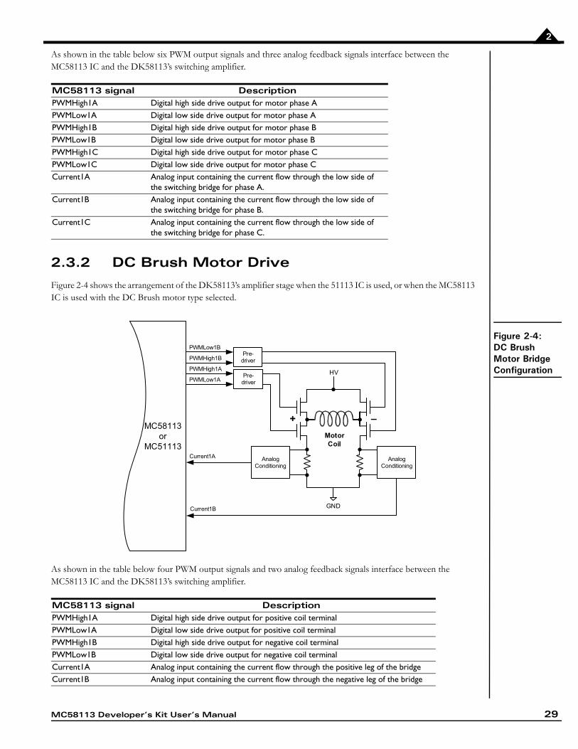
2.3.2 DC Brush Motor Drive
Figure 2-4 shows the arrangement of the DK58113’s amplifier stage when the 51113 IC is used, or when the MC58113 IC is used with the DC Brush motor type selected.
Figure 2-4:DC Brush Motor Bridge Configuration
As shown in the table below four PWM output signals and two analog feedback signals interface between the MC58113 IC and the DK58113’s switching amplifier.
MC58113 signal DescriptionPWMHigh1A Digital high side drive output for motor phase APWMLow1A Digital low side drive output for motor phase APWMHigh1B Digital high side drive output for motor phase BPWMLow1B Digital low side drive output for motor phase BPWMHigh1C Digital high side drive output for motor phase CPWMLow1C Digital low side drive output for motor phase CCurrent1A Analog input containing the current flow through the low side of
the switching bridge for phase A.Current1B Analog input containing the current flow through the low side of
the switching bridge for phase B.Current1C Analog input containing the current flow through the low side of
the switching bridge for phase C.
MC58113 signal DescriptionPWMHigh1A Digital high side drive output for positive coil terminal PWMLow1A Digital low side drive output for positive coil terminalPWMHigh1B Digital high side drive output for negative coil terminalPWMLow1B Digital low side drive output for negative coil terminalCurrent1A Analog input containing the current flow through the positive leg of the bridgeCurrent1B Analog input containing the current flow through the negative leg of the bridge
MC58113 or
MC51113 Current1A
Current1B GND
HV
AnalogConditioning
AnalogConditioning
MotorCoil
PWMLow1B
PWMHigh1B
PWMHigh1A
PWMLow1A
+ –
Pre-driver
Pre-driver
30 MC58113 Developer’s Kit User’s Manual
2
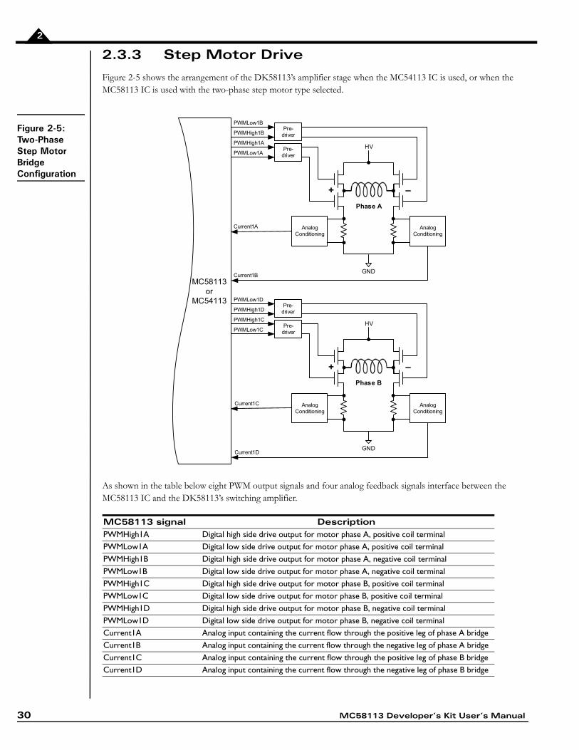
2.3.3 Step Motor Drive
Figure 2-5 shows the arrangement of the DK58113’s amplifier stage when the MC54113 IC is used, or when the MC58113 IC is used with the two-phase step motor type selected.
Figure 2-5:Two-Phase Step Motor Bridge Configuration
As shown in the table below eight PWM output signals and four analog feedback signals interface between the MC58113 IC and the DK58113’s switching amplifier.
MC58113 signal DescriptionPWMHigh1A Digital high side drive output for motor phase A, positive coil terminalPWMLow1A Digital low side drive output for motor phase A, positive coil terminalPWMHigh1B Digital high side drive output for motor phase A, negative coil terminalPWMLow1B Digital low side drive output for motor phase A, negative coil terminalPWMHigh1C Digital high side drive output for motor phase B, positive coil terminalPWMLow1C Digital low side drive output for motor phase B, positive coil terminalPWMHigh1D Digital high side drive output for motor phase B, negative coil terminalPWMLow1D Digital low side drive output for motor phase B, negative coil terminalCurrent1A Analog input containing the current flow through the positive leg of phase A bridge Current1B Analog input containing the current flow through the negative leg of phase A bridge Current1C Analog input containing the current flow through the positive leg of phase B bridge Current1D Analog input containing the current flow through the negative leg of phase B bridge
PWMLow1B
PWMHigh1B
PWMHigh1A
PWMLow1A
Current1A
Current1BGND
HV
AnalogConditioning
AnalogConditioning
Phase A
Phase B
MC58113 or
MC54113
Current1C
Current1DGND
HV
AnalogConditioning
AnalogConditioning
PWMLow1D
PWMHigh1D
PWMHigh1C
PWMLow1C
+ –
+ –
Pre-driver
Pre-driver
Pre-driver
Pre-driver
MC58113 Developer’s Kit User’s Manual 31
2
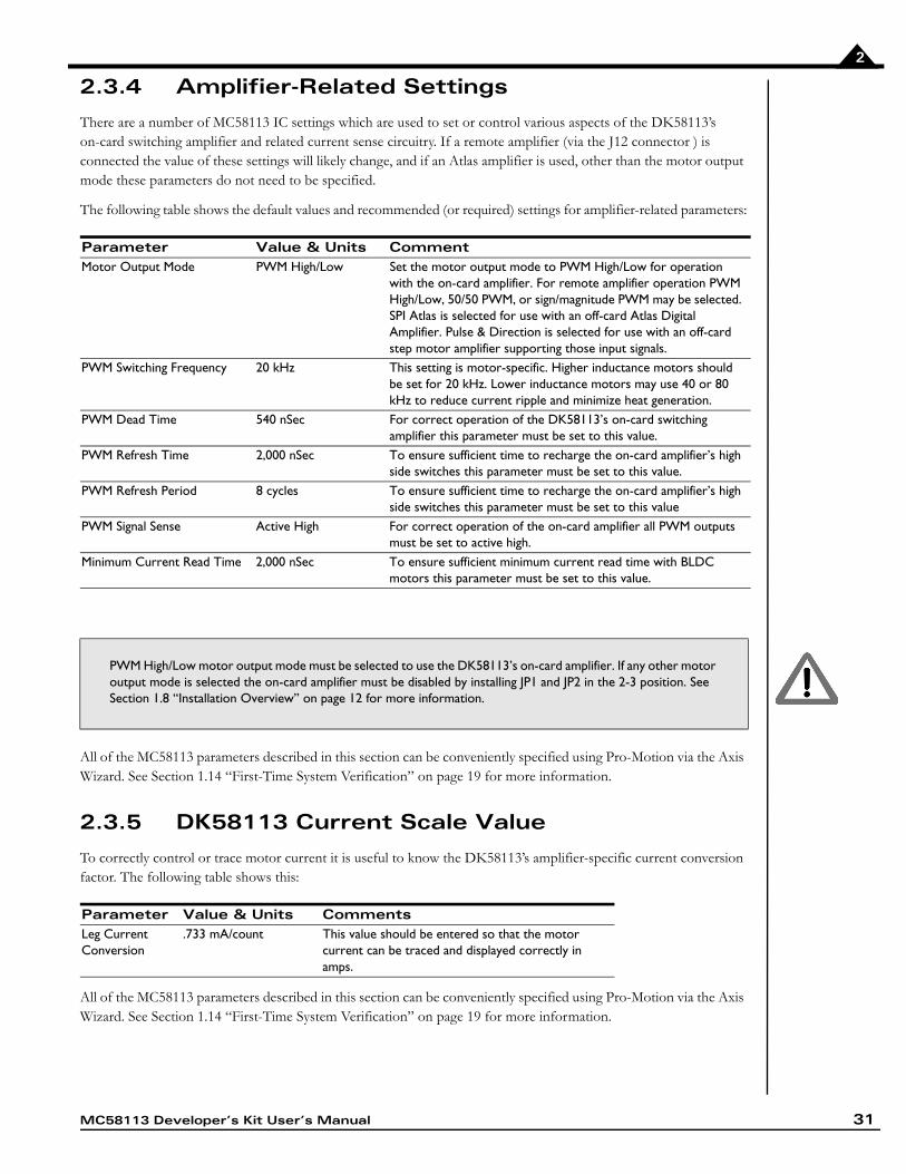
2.3.4 Amplifier-Related Settings
There are a number of MC58113 IC settings which are used to set or control various aspects of the DK58113’s on-card switching amplifier and related current sense circuitry. If a remote amplifier (via the J12 connector ) is connected the value of these settings will likely change, and if an Atlas amplifier is used, other than the motor output mode these parameters do not need to be specified.
The following table shows the default values and recommended (or required) settings for amplifier-related parameters:
All of the MC58113 parameters described in this section can be conveniently specified using Pro-Motion via the Axis Wizard. See Section 1.14 “First-Time System Verification” on page 19 for more information.
2.3.5 DK58113 Current Scale Value
To correctly control or trace motor current it is useful to know the DK58113’s amplifier-specific current conversion factor. The following table shows this:
All of the MC58113 parameters described in this section can be conveniently specified using Pro-Motion via the Axis Wizard. See Section 1.14 “First-Time System Verification” on page 19 for more information.
Parameter Value & Units CommentMotor Output Mode PWM High/Low Set the motor output mode to PWM High/Low for operation
with the on-card amplifier. For remote amplifier operation PWM High/Low, 50/50 PWM, or sign/magnitude PWM may be selected. SPI Atlas is selected for use with an off-card Atlas Digital Amplifier. Pulse & Direction is selected for use with an off-card step motor amplifier supporting those input signals.
PWM Switching Frequency 20 kHz This setting is motor-specific. Higher inductance motors should be set for 20 kHz. Lower inductance motors may use 40 or 80 kHz to reduce current ripple and minimize heat generation.
PWM Dead Time 540 nSec For correct operation of the DK58113’s on-card switching amplifier this parameter must be set to this value.
PWM Refresh Time 2,000 nSec To ensure sufficient time to recharge the on-card amplifier’s high side switches this parameter must be set to this value.
PWM Refresh Period 8 cycles To ensure sufficient time to recharge the on-card amplifier’s high side switches this parameter must be set to this value
PWM Signal Sense Active High For correct operation of the on-card amplifier all PWM outputs must be set to active high.
Minimum Current Read Time 2,000 nSec To ensure sufficient minimum current read time with BLDC motors this parameter must be set to this value.
PWM High/Low motor output mode must be selected to use the DK58113’s on-card amplifier. If any other motor output mode is selected the on-card amplifier must be disabled by installing JP1 and JP2 in the 2-3 position. See Section 1.8 “Installation Overview” on page 12 for more information.
Parameter Value & Units CommentsLeg Current Conversion
.733 mA/count This value should be entered so that the motor current can be traced and displayed correctly in amps.
32 MC58113 Developer’s Kit User’s Manual
2
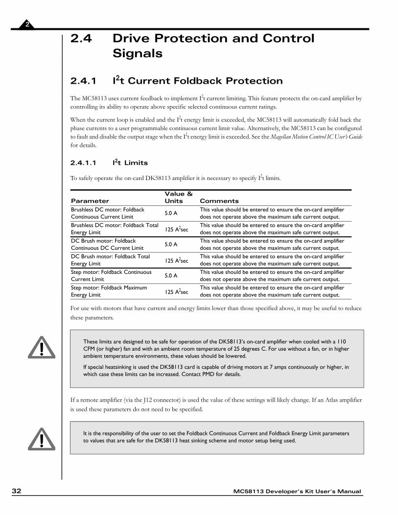
2.4 Drive Protection and Control Signals
2.4.1 I2t Current Foldback Protection
The MC58113 uses current feedback to implement I2t current limiting. This feature protects the on-card amplifier by controlling its ability to operate above specific selected continuous current ratings.
When the current loop is enabled and the I2t energy limit is exceeded, the MC58113 will automatically fold back the phase currents to a user programmable continuous current limit value. Alternatively, the MC58113 can be configured to fault and disable the output stage when the I2t energy limit is exceeded. See the Magellan Motion Control IC User’s Guide for details.
2.4.1.1 I2t Limits
To safely operate the on-card DK58113 amplifier it is necessary to specify I2t limits.
For use with motors that have current and energy limits lower than those specified above, it may be useful to reduce
these parameters.
If a remote amplifier (via the J12 connector) is used the value of these settings will likely change. If an Atlas amplifier
is used these parameters do not need to be specified.
ParameterValue & Units Comments
Brushless DC motor: Foldback Continuous Current Limit
5.0 AThis value should be entered to ensure the on-card amplifier does not operate above the maximum safe current output.
Brushless DC motor: Foldback Total Energy Limit 125 A2sec
This value should be entered to ensure the on-card amplifier does not operate above the maximum safe current output.
DC Brush motor: Foldback Continuous DC Current Limit
5.0 AThis value should be entered to ensure the on-card amplifier does not operate above the maximum safe current output.
DC Brush motor: Foldback Total Energy Limit 125 A2sec
This value should be entered to ensure the on-card amplifier does not operate above the maximum safe current output.
Step motor: Foldback Continuous Current Limit
5.0 AThis value should be entered to ensure the on-card amplifier does not operate above the maximum safe current output.
Step motor: Foldback Maximum Energy Limit 125 A2sec
This value should be entered to ensure the on-card amplifier does not operate above the maximum safe current output.
These limits are designed to be safe for operation of the DK58113’s on-card amplifier when cooled with a 110 CFM (or higher) fan and with an ambient room temperature of 25 degrees C. For use without a fan, or in higher ambient temperature environments, these values should be lowered.
If special heatsinking is used the DK58113 card is capable of driving motors at 7 amps continuously or higher, in which case these limits can be increased. Contact PMD for details.
It is the responsibility of the user to set the Foldback Continuous Current and Foldback Energy Limit parameters to values that are safe for the DK58113 heat sinking scheme and motor setup being used.
MC58113 Developer’s Kit User’s Manual 33
2
All of the MC58113 parameters described in this section can be conveniently specified using Pro-Motion via the Axis Wizard. See Section 1.14 “First-Time System Verification” on page 19 for more information.
2.4.2 Overtemperature Protection
The DK58113 uses a temperature sensor to continuously monitor the temperature of the on-card power MOSFETs.
2.4.2.1 Converting Temperature Readings into Degrees C
The MC58113 IC inputs temperature readings via its Temperature analog input and performs related functions such as over temperature checking without converting the readings from the attached temperature sensor into degrees C. It does this by comparing temperature in units of ‘counts,’ meaning the numerical value of the Temperature signal converted by the MC58113’s on-chip A/D.
While using Pro-Motion however, it is convenient to be able to view and trace the amplifier temperature in units of degrees C. This is accomplished by providing a conversion table to Pro-Motion.
Note that use of this table is optional and is only required if display of temperature via Pro-Motion is desired with units of degrees C. In any case, for the DK58113, the table “DK58113 Temp Table.txt” should be selected. See the Pro-Motion Users Manual for more information on how to select thermistor conversion tables.
2.4.2.2 Temperature Limit
The following temperature limit is required to safely operate the DK58113 card.
If an Atlas amplifier is used these temperature limit values do not need to be specified.
All of the MC58113 parameters described in this section can be conveniently specified using Pro-Motion via the Axis Wizard. See Section 1.14 “First-Time System Verification” on page 19 for more information.
Parameter Value & Units CommentsTemperature limit 75.0 C This value should be entered to ensure that the amplifier
does not operate above the maximum safe temperature
The DK58113’s temperature sensor is located on the DK58113 card and therefore will not function correctly when a remote amplifier is used.
34 MC58113 Developer’s Kit User’s Manual
2
2.5 DC Bus
Figure 2-6:DC Bus Monitoring Circuitry
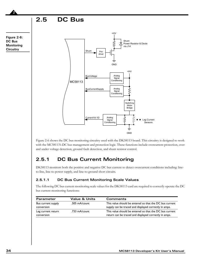
Figure 2-6 shows the DC bus monitoring circuitry used with the DK58113 board. This circuitry is designed to work with the MC58113’s DC bus management and protection logic. These functions include overcurrent protection, over and under voltage detection, ground fault detection, and shunt resistor control.
2.5.1 DC Bus Current Monitoring
DK58113 monitors both the positive and negative DC bus current to detect overcurrent conditions including: line-to-line, line-to-power supply, and line-to-ground short circuits.
2.5.1.1 DC Bus Current Monitoring Scale Values
The following DC bus current monitoring scale values for the DK58113 card are required to correctly operate the DC bus current monitoring functions:
Parameter Value & Units CommentsBus current supply conversion
.505 mA/count This value should be entered so that the DC bus current supply can be traced and displayed correctly in amps.
Leg current return conversion
.733 mA/count This value should be entered so that the DC bus current return can be traced and displayed correctly in amps.
+HV
GND
MC581130
Shunt Pre-driver
AnalogSignal
Conditioning
BusVoltage
+HV
AnalogSignal
Conditioning
BusCurrentSupply
Current1A-1D
SwitchingMotorBridge
ShuntPower Resistor & Diodevia J14
AnalogSignal
Conditioning
GND
Leg CurrentSensors
MC58113 Developer’s Kit User’s Manual 35
2
2.5.1.2 DC Bus Current Limits
The following MC58113 DC bus current limits are required to safely operate the DK58113 card:
Note that these values are designed to protect the DK58113 circuitry. Lower values may be used to protect the motor.
If an Atlas amplifier is used these DC bus current scale and limit values do not need to be set.
All of the MC58113 parameters described in this section can be conveniently specified using Pro-Motion via the Axis Wizard. See Section 1.14 “First-Time System Verification” on page 19 for more information
2.5.2 DC Bus Voltage Monitoring
DK58113 monitors the main DC bus voltage for overvoltage and undervoltage conditions. These thresholds are user-settable within the voltage operating range of the drive. DC bus voltage monitoring may operate even when a remote amplifier is used, as long as the +HV supply is still connected to the DK58113.
2.5.2.1 DC Bus Voltage Monitoring Scale Values
To correctly monitor the DK58113 DC bus voltage it is necessary to know the DC bus voltage scale factor. The following table provides this value.
2.5.2.2 DC Bus Voltage Limits
The following MC58113 DC bus voltage limits are required to safely operate the DK58113 card:
Note that these values are designed to protect the DK58113 circuitry. More restrictive values may be used to protect the motor.
All of the MC58113 parameters described in this section can be conveniently specified using Pro-Motion via the Axis Wizard. See Section 1.14 “First-Time System Verification” on page 19 for more information.
2.5.3 Shunt Resistor & Diode
J14 provides a connection for a shunt resistor and diode that may be used to regulate overvoltage conditions on the DC bus. Such conditions can occur during deceleration of a motor with a large inertia.
Parameter Value & Units CommentsBus Current Supply Limit 20.0 A This value should be entered to ensure safe
operation of the DK58113.Bus Current Return Limit 20.0 A This value should be entered to ensure safe
operation of the DK58113.
DC bus current monitoring functions will not work when a remote amplifier is used.
Parameter Value & Units CommentsBus Voltage Display .966 mV/count This value should be entered so that the DC bus voltage
can be traced and displayed correctly in volts.
Parameter Value & Units CommentsUndervoltage Limit 10.0 V This value should be entered to ensure safe
operation of the DK58113.Overvoltage Limit 60.0 V This value should be entered to ensure safe
operation of the DK58113.
36 MC58113 Developer’s Kit User’s Manual
2
As shown in Figure 2-6 the MC58113 provides a shunt PWM output, which in turn drives a MOSFET switch on the DK58113 card.
The resistor connected at J14 should have a resistance such that the current flow through the Shunt MOSFET does not exceed 10 amps. For example with an HV supply of 48 Volts, this means a resistance of no less than 4.8 ohms. The diode, which is connected in parallel to the resistor, should have a voltage and current rating at least equal to those of the MOSFET. For the DK58113 this means a voltage and current rating of 100 volts and 10 amps or higher.
Beyond this limit, the actual resistance used is application specific and depends on the nature of the anticipated over voltage generating conditions, the power supply used, and the wattage rating of the resistor.
Example: a shunt resistor with a resistance of 10 ohms is connected through the J4 shunt connector and a comparison value of 51 Volts and a PWM duty cycle of 75% are specified. When the +HV voltage exceeds 51.0 Volts, HV will be connected to GND via the shunt resistor resulting in an effective average current flow of (51.0V * .75)/10 ohms = 3.825 amps.
The default value of the shunt comparison mechanism is disabled. To enable, both a voltage comparison value and a
PWM output duty cycle are specified. See the Pro-Motion User’s Manual for details.
2.6 Connecting to a Remote Amplifier
Figure 2-7:DK58113 to Remote Amplifier Card Connections
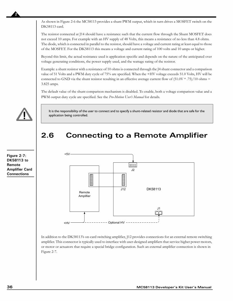
In addition to the DK58113’s on-card switching amplifier, J12 provides connections for an external remote switching amplifier. This connector is typically used to interface with user-designed amplifiers that service higher power motors, or motor or actuators that require a special bridge configuration. Such an external amplifier connection is shown in Figure 2-7.
It is the responsibility of the user to connect and to specify a shunt-related resistor and diode that are safe for the application being controlled.
RemoteAmplifier
DK58113
J1
J2
J12
+5V
+HV Optional HV
MC58113 Developer’s Kit User’s Manual 37
2
Note that connection of the remote amplifiers HV supply to the DK58113 card is optional. Doing so allows use of
the DK58113’s over and undervoltage check feature.
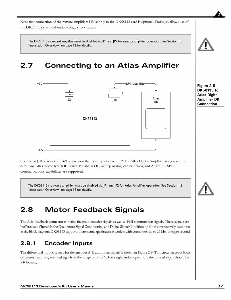
2.7 Connecting to an Atlas Amplifier
Figure 2-8:DK58113 to Atlas Digital Amplifier DK Connection
Connector J10 provides a DB-9 connection that is compatible with PMD’s Atlas Digital Amplifier single-axis DK card. Any Atlas motor type (DC Brush, Brushless DC, or step motor) can be driven, and Atlas's full SPI
communications capabilities are supported.
2.8 Motor Feedback Signals
The Axis Feedback connector contains the main encoder signals as well as Hall commutation signals. These signals are buffered and filtered in the Quadrature Signal Conditioning and Digital Signal Conditioning blocks, respectively, as shown in the block diagram. DK58113 supports incremental quadrature encoders with count rates up to 25 Mcounts per second.
2.8.1 Encoder Inputs
The differential input circuitry for the encoder A, B and Index signals is shown in Figure 2-9. This circuit accepts both differential and single-ended signals in the range of 0 – 5 V. For single-ended operation, the unused input should be left floating.
The DK58113’s on-card amplifier must be disabled via JP1 and JP2 for remote amplifier operation. See Section 1.8 “Installation Overview” on page 12 for details.
The DK58113’s on-card amplifier must be disabled via JP1 and JP2 for Atlas Amplifier operation. See Section 1.8 “Installation Overview” on page 12 for details.
DK58113
J10J2
MC58113
SPI Atlas Bus+5V
+HV
AtlasDK
38 MC58113 Developer’s Kit User’s Manual
2
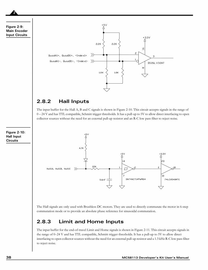
Figure 2-9:Main Encoder Input Circuits
2.8.2 Hall Inputs
The input buffer for the Hall A, B and C signals is shown in Figure 2-10. This circuit accepts signals in the range of 0 – 24 V and has TTL compatible, Schmitt trigger thresholds. It has a pull-up to 5V to allow direct interfacing to open collector sources without the need for an external pull-up resistor and an R-C low pass filter to reject noise.
Figure 2-10:Hall Input Circuits
The Hall signals are only used with Brushless DC motors. They are used to directly commutate the motor in 6-step commutation mode or to provide an absolute phase reference for sinusoidal commutation.
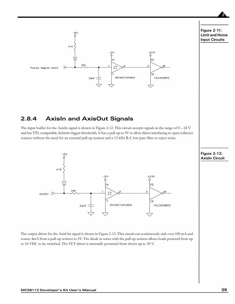
2.8.3 Limit and Home Inputs
The input buffer for the end-of-travel Limit and Home signals is shown in Figure 2-11. This circuit accepts signals in the range of 0–24 V and has TTL compatible, Schmitt trigger thresholds. It has a pull-up to 5V to allow direct interfacing to open collector sources without the need for an external pull-up resistor and a 1.3 kHz R-C low pass filter to reject noise.
MC58113 Developer’s Kit User’s Manual 39
2
Figure 2-11:Limit and Home Input Circuits
2.8.4 AxisIn and AxisOut Signals
The input buffer for the AxisIn signal is shown in Figure 2-12. This circuit accepts signals in the range of 0 – 24 V and has TTL compatible, Schmitt trigger thresholds. It has a pull-up to 5V to allow direct interfacing to open collector sources without the need for an external pull-up resistor and a 13 kHz R-C low pass filter to reject noise.
Figure 2-12:AxisIn Circuit
The output driver for the AxisOut signal is shown in Figure 2-13. This circuit can continuously sink over 100 mA and source 4mA from a pull-up resistor to 5V. The diode in series with the pull-up resistor allows loads powered from up to 24 VDC to be switched. The FET driver is internally protected from shorts up to 30 V.
40 MC58113 Developer’s Kit User’s Manual
2
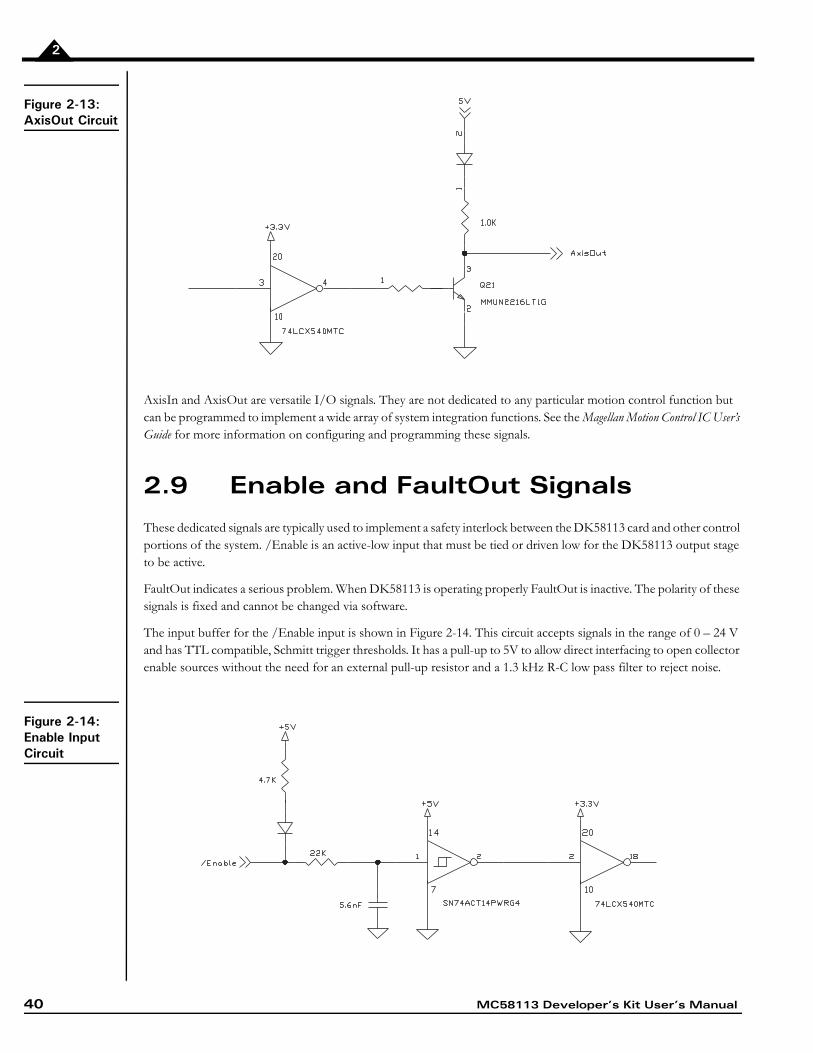
Figure 2-13:AxisOut Circuit
AxisIn and AxisOut are versatile I/O signals. They are not dedicated to any particular motion control function but can be programmed to implement a wide array of system integration functions. See the Magellan Motion Control IC User’s Guide for more information on configuring and programming these signals.
2.9 Enable and FaultOut Signals
These dedicated signals are typically used to implement a safety interlock between the DK58113 card and other control portions of the system. /Enable is an active-low input that must be tied or driven low for the DK58113 output stage to be active.
FaultOut indicates a serious problem. When DK58113 is operating properly FaultOut is inactive. The polarity of these signals is fixed and cannot be changed via software.
The input buffer for the /Enable input is shown in Figure 2-14. This circuit accepts signals in the range of 0 – 24 V and has TTL compatible, Schmitt trigger thresholds. It has a pull-up to 5V to allow direct interfacing to open collector enable sources without the need for an external pull-up resistor and a 1.3 kHz R-C low pass filter to reject noise.
Figure 2-14:Enable Input Circuit
MC58113 Developer’s Kit User’s Manual 41
2
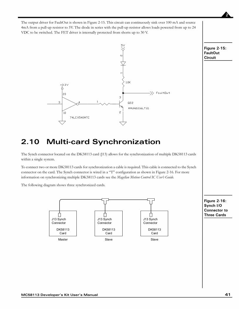
The output driver for FaultOut is shown in Figure 2-15. This circuit can continuously sink over 100 mA and source 4mA from a pull-up resistor to 5V. The diode in series with the pull-up resistor allows loads powered from up to 24 VDC to be switched. The FET driver is internally protected from shorts up to 30 V.
Figure 2-15:FaultOut Circuit
2.10 Multi-card Synchronization
The Synch connector located on the DK58113 card (J13) allows for the synchronization of multiple DK58113 cards within a single system.
To connect two or more DK58113 cards for synchronization a cable is required. This cable is connected to the Synch connector on the card. The Synch connector is wired in a “T” configuration as shown in Figure 2-16. For more information on synchronizing multiple DK58113 cards see the Magellan Motion Control IC User’s Guide.
The following diagram shows three synchronized cards.
Figure 2-16:Synch I/O Connector to Three Cards
Master Slave Slave
J13 SynchConnector
DK58113Card
J13 SynchConnector
DK58113Card
J13 SynchConnector
DK58113Card

42 MC58113 Developer’s Kit User’s Manual
2
2.11 On-IC NVRAM Configuration Storage
The MC58113-series ICs provide the ability to directly store configuration information such as gain parameters, drive-related safety parameters, and other parameters. This setup information, once loaded, is automatically initialized into the MC58113's active configuration registers at each power-up. When used in an actual control system the NVRAM may therefore be useful to reduce or eliminate communications to the MC58113 IC during powerup. See the Magellan Motion Control IC User’s Guide for more information on MC58113-series ICs powerup.
While developing a new MC58113-based application it is not recommended that the on-IC NVRAM be used to store configuration data. Pro-Motion can store a wide variety of configuration parameters using its Save Project and Load Project menu functions, and this generally represents a more flexible and general purpose approach.
Nevertheless, when ready, MC58113 configuration parameter programming or re-programming can be conveniently accomplished using Pro-Motion. See the Pro-Motion User’s Manual for details.
3
3.Electrical Reference In This ChapterUser-Settable ComponentsConnectorsMotor Connection Quick ReferenceAbsolute Maximum RatingsEnvironmental and Electrical RatingsDK58113 On-Card Amplifier Quick Reference3.1 User-Settable Components
The following table details the available DK58113 jumper settings, which are the DK58113’s only user-settable hard-ware components:
Jumper IDFactory Default Setting Setting & Description
JP1, JP2 1-2 (on-card amplifier) 1-2 Installing jumpers at 1-2 for JP1 and JP2 configures the DK58113 for operation of the on-card amplifier.
2-3 Installing jumpers at 2-3 for JP1 and JP2 disables the on-card amplifier, and configures the DK58113 for operation with a user-designed amplifier via the J12 Remote Amplifier Connector, or with an Atlas DK amplifier via the J10 connector.
JP4 1-2 (RS-232) 1-2 Installing a jumper at 1-2 for JP4 configures the DK58113 for RS-232 serial operation.
2-3 Installing a jumper at 2-3 for JP4 configures the DK58113 for RS-485 serial operation.
MC58113 Developer’s Kit User’s Manual 43
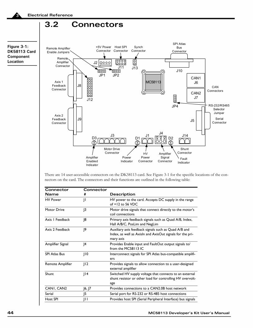
Electrical Reference3
3.2 Connectors
Figure 3-1:DK58113 Card Component Location
There are 14 user-accessible connectors on the DK58113 card. See Figure 3-1 for the specific locations of the con-nectors on the card. The connectors and their functions are outlined in the following table:
Connector Name
Connector # Description
HV Power J1 HV power to the card. Accepts DC supply in the range of +12 to 56 VDC
Motor Drive J3 Motor drive signals that connect directly to the motor's coil connections
Axis 1 Feedback J8 Primary axis feedback signals such as Quad A/B, Index, Hall A/B/C, PosLim and NegLim
Axis 2 Feedback J9 Auxiliary axis feedback signals such as Quad A/B and Index, as well as AxisIn and AxisOut signals for the pri-mary axis
Amplifier Signal J4 Provides Enable input and FaultOut output signals to/from the MC58113 IC
SPI Atlas Bus J10 Interconnect signals for SPI Atlas bus-compatible amplifi-ers
Remote Amplifier J12 Provides signals to allow connection to a user-designed external amplifier
Shunt J14 Switched HV supply voltage that connects to an external shunt resistor or other load for controlling HV overvolt-age
CAN1, CAN2 J6, J7 Provides connections to a CAN2.0B host networkSerial J5 Serial port for RS-232 or RS-485 host connectionsHost SPI J11 Provides host SPI (Serial Peripheral Interface) bus signals
CAN2J7
CAN1J6
CAN Connectors
J1J3
HVPower
Connector
Motor Drive Connector
J14
Shunt Connector
J5 Serial Connector
J11
Host SPI Connector
J13
Synch Connector
J10
SPI AtlasBus
Connector
Axis 1FeedbackConnector
Axis 2FeedbackConnector
J2
+5V Power Connector
J12
RemoteAmplifier
Connector
JP1 JP2
Remote AmplifierEnable Jumpers
D1 D2D3J4
AmplifierSignal
Connector
JP4 RS-232/RS485Selector Jumper
AmplifierEnabledIndicator
PowerIndicator
FaultIndicator
J9
J8MC58113
44 MC58113 Developer’s Kit User’s Manual
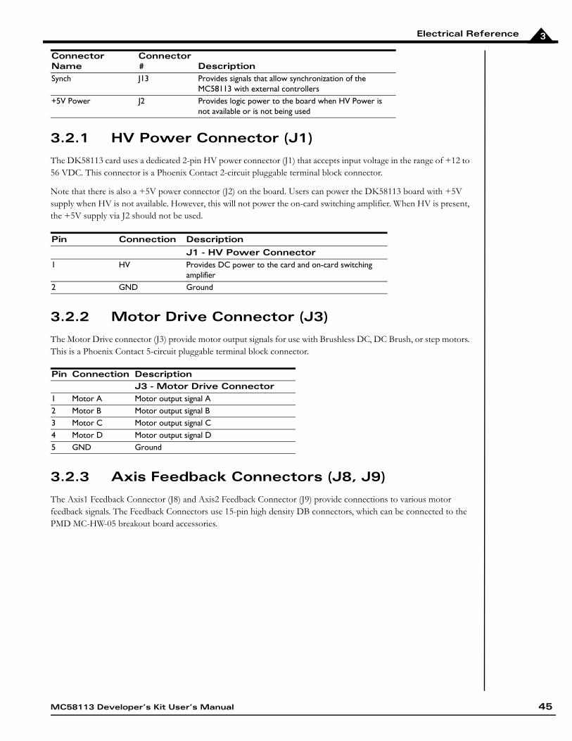
Electrical Reference 3
3.2.1 HV Power Connector (J1)
The DK58113 card uses a dedicated 2-pin HV power connector (J1) that accepts input voltage in the range of +12 to 56 VDC. This connector is a Phoenix Contact 2-circuit pluggable terminal block connector.
Note that there is also a +5V power connector (J2) on the board. Users can power the DK58113 board with +5V supply when HV is not available. However, this will not power the on-card switching amplifier. When HV is present, the +5V supply via J2 should not be used.
3.2.2 Motor Drive Connector (J3)
The Motor Drive connector (J3) provide motor output signals for use with Brushless DC, DC Brush, or step motors. This is a Phoenix Contact 5-circuit pluggable terminal block connector.
3.2.3 Axis Feedback Connectors (J8, J9)
The Axis1 Feedback Connector (J8) and Axis2 Feedback Connector (J9) provide connections to various motor feedback signals. The Feedback Connectors use 15-pin high density DB connectors, which can be connected to the PMD MC-HW-05 breakout board accessories.
Synch J13 Provides signals that allow synchronization of the MC58113 with external controllers
+5V Power J2 Provides logic power to the board when HV Power is not available or is not being used
Pin Connection DescriptionJ1 - HV Power Connector
1 HV Provides DC power to the card and on-card switching amplifier
2 GND Ground
Pin Connection DescriptionJ3 - Motor Drive Connector
1 Motor A Motor output signal A2 Motor B Motor output signal B3 Motor C Motor output signal C4 Motor D Motor output signal D5 GND Ground
Connector Name
Connector # Description
MC58113 Developer’s Kit User’s Manual 45
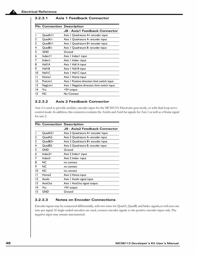
Electrical Reference3
3.2.3.1 Axis 1 Feedback Connector
3.2.3.2 Axis 2 Feedback Connector
Axis 2 is used to provide auxiliary encoder input for the MC58113’s Electronic gear mode, or with dual loop servo control mode. In addition, this connector contains the AxisIn and AxisOut signals for Axis 1 as well as a Home signal for axis 2.
3.2.3.3 Notes on Encoder Connections
Encoder inputs may be connected differentially, with two wires for QuadA, QuadB, and Index signals,or with just one wire per signal. If single-ended encoders are used, connect encoder signals to the positive encoder input only. The negative input may remain unconnected.
Pin Connection DescriptionJ8 - Axis1 Feedback Connector
1 QuadA1+ Axis 1 Quadrature A+ encoder input 2 QuadA1- Axis 1 Quadrature A- encoder input3 QuadB1+ Axis 1 Quadrature B+ encoder input4 QuadB1- Axis 1 Quadrature B- encoder input5 GND Ground6 Index1+ Axis 1 Index+ input7 Index1- Axis 1 Index- input8 Hall1A Axis 1 Hall A input 9 Hall1B Axis 1 Hall B input 10 Hall1C Axis 1 Hall C input 11 Home1 Axis 1 Home input12 PosLim1 Axis 1 Positive direction limit switch input13 NegLim1 Axis 1 Negative direction limit switch input14 Vcc +5V output15 NC No Connect
Pin Connection DescriptionJ9 - Axis2 Feedback Connector
1 QuadA2+ Axis 2 Quadrature A+ encoder input 2 QuadA2- Axis 2 Quadrature A- encoder input3 QuadB2+ Axis 2 Quadrature B+ encoder input4 QuadB2- Axis 2 Quadrature B- encoder input5 GND Ground6 Index2+ Axis 2 Index+ input7 Index2- Axis 2 Index- input8 NC no connect9 NC no connect10 NC no connect11 Home2 Axis 2 Home input12 AxisIn Axis 1 AxisIn signal input13 AxisOut Axis 1 AxisOut signal output14 Vcc +5V output15 GND Ground
46 MC58113 Developer’s Kit User’s Manual
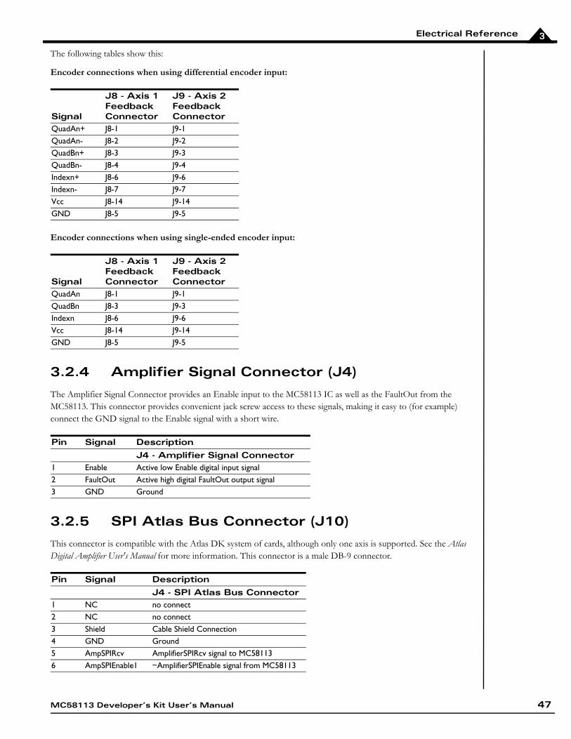
Electrical Reference 3
The following tables show this:
Encoder connections when using differential encoder input:
Encoder connections when using single-ended encoder input:
3.2.4 Amplifier Signal Connector (J4)
The Amplifier Signal Connector provides an Enable input to the MC58113 IC as well as the FaultOut from the MC58113. This connector provides convenient jack screw access to these signals, making it easy to (for example) connect the GND signal to the Enable signal with a short wire.
3.2.5 SPI Atlas Bus Connector (J10)
This connector is compatible with the Atlas DK system of cards, although only one axis is supported. See the Atlas Digital Amplifier User's Manual for more information. This connector is a male DB-9 connector.
Signal
J8 - Axis 1 Feedback Connector
J9 - Axis 2 Feedback Connector
QuadAn+ J8-1 J9-1QuadAn- J8-2 J9-2QuadBn+ J8-3 J9-3QuadBn- J8-4 J9-4Indexn+ J8-6 J9-6Indexn- J8-7 J9-7Vcc J8-14 J9-14GND J8-5 J9-5
Signal
J8 - Axis 1 Feedback Connector
J9 - Axis 2 Feedback Connector
QuadAn J8-1 J9-1QuadBn J8-3 J9-3Indexn J8-6 J9-6Vcc J8-14 J9-14GND J8-5 J9-5
Pin Signal DescriptionJ4 - Amplifier Signal Connector
1 Enable Active low Enable digital input signal2 FaultOut Active high digital FaultOut output signal3 GND Ground
Pin Signal DescriptionJ4 - SPI Atlas Bus Connector
1 NC no connect2 NC no connect3 Shield Cable Shield Connection4 GND Ground5 AmpSPIRcv AmplifierSPIRcv signal to MC581136 AmpSPIEnable1 ~AmplifierSPIEnable signal from MC58113
MC58113 Developer’s Kit User’s Manual 47
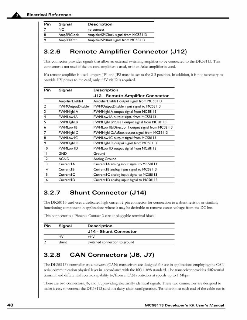
Electrical Reference3
3.2.6 Remote Amplifier Connector (J12)
This connector provides signals that allow an external switching amplifier to be connected to the DK58113. This connector is not used if the on-card amplifier is used, or if an Atlas amplifier is used.
If a remote amplifier is used jumpers JP1 and JP2 must be set to the 2-3 position. In addition, it is not necessary to provide HV power to the card, only +5V via J2 is required.
3.2.7 Shunt Connector (J14)
The DK58113 card uses a dedicated high current 2-pin connector for connection to a shunt resistor or similarly functioning component in applications where it may be desirable to remove excess voltage from the DC bus.
This connector is a Phoenix Contact 2-circuit pluggable terminal block.
3.2.8 CAN Connectors (J6, J7)
The DK58113’s controller are a network (CAN) transceivers are designed for use in applications employing the CAN serial communication physical layer in accordance with the ISO11898 standard. The transceiver provides differential transmit and differential receive capability to/from a CAN controller at speeds up to 1 Mbps.
There are two connectors, J6, and J7, providing electrically identical signals. These two connectors are designed to make it easy to connect the DK58113 card in a daisy-chain configuration. Termination at each end of the cable run is
7 NC no connect8 AmpSPIClock AmplifierSPIClock signal from MC581139 AmpSPIXmt AmplifierSPIXmt signal from MC58113
Pin Signal DescriptionJ12 - Remote Amplifier Connector
1 AmplifierEnable1 AmplifierEnable1 output signal from MC581132 PWMOutputDisable PWMOutputDisable input signal to MC581133 PWMHigh1A PWMHigh1A output signal from MC581134 PWMLow1A PWMLow1A output signal from MC581135 PWMHigh1B PWMHigh1B/Pulse1 output signal from MC581136 PWMLow1B PWMLow1B/Direction1 output signal from MC581137 PWMHigh1C PWMHigh1C/AtRest output signal from MC581138 PWMLow1C PWMLow1C output signal from MC581139 PWMHigh1D PWMHigh1D output signal from MC5811310 PWMLow1D PWMLow1D output signal from MC5811311 GND Ground12 AGND Analog Ground13 Current1A Current1A analog input signal to MC5811314 Current1B Current1B analog input signal to MC5811315 Current1C Current1C analog input signal to MC5811316 Current1D Current1D analog input signal to MC58113
Pin Signal DescriptionJ14 - Shunt Connector
1 HV +HV2 Shunt Switched connection to ground
Pin Signal Description
48 MC58113 Developer’s Kit User’s Manual
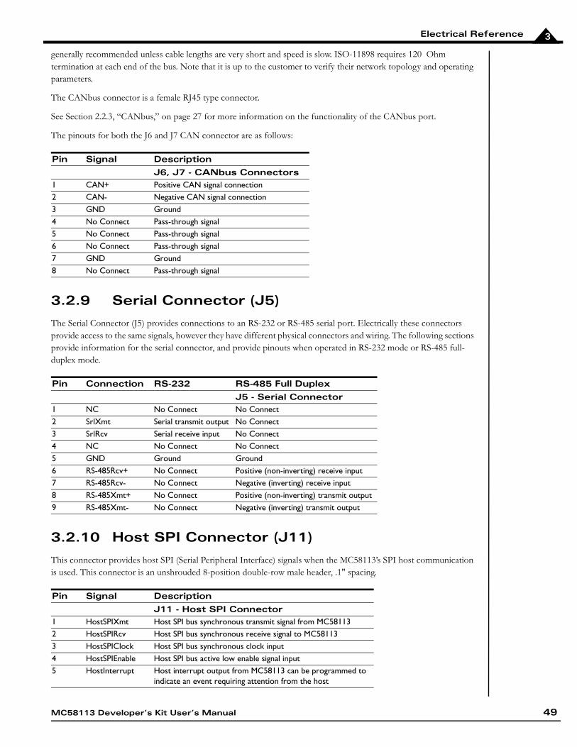
Electrical Reference 3
generally recommended unless cable lengths are very short and speed is slow. ISO-11898 requires 120 Ohm termination at each end of the bus. Note that it is up to the customer to verify their network topology and operating parameters.
The CANbus connector is a female RJ45 type connector.
See Section 2.2.3, “CANbus,” on page 27 for more information on the functionality of the CANbus port.
The pinouts for both the J6 and J7 CAN connector are as follows:
3.2.9 Serial Connector (J5)
The Serial Connector (J5) provides connections to an RS-232 or RS-485 serial port. Electrically these connectors provide access to the same signals, however they have different physical connectors and wiring. The following sections provide information for the serial connector, and provide pinouts when operated in RS-232 mode or RS-485 full-duplex mode.
3.2.10 Host SPI Connector (J11)
This connector provides host SPI (Serial Peripheral Interface) signals when the MC58113’s SPI host communication is used. This connector is an unshrouded 8-position double-row male header, .1" spacing.
Pin Signal DescriptionJ6, J7 - CANbus Connectors
1 CAN+ Positive CAN signal connection2 CAN- Negative CAN signal connection3 GND Ground4 No Connect Pass-through signal5 No Connect Pass-through signal6 No Connect Pass-through signal7 GND Ground8 No Connect Pass-through signal
Pin Connection RS-232 RS-485 Full DuplexJ5 - Serial Connector
1 NC No Connect No Connect2 SrlXmt Serial transmit output No Connect3 SrlRcv Serial receive input No Connect4 NC No Connect No Connect5 GND Ground Ground6 RS-485Rcv+ No Connect Positive (non-inverting) receive input7 RS-485Rcv- No Connect Negative (inverting) receive input8 RS-485Xmt+ No Connect Positive (non-inverting) transmit output9 RS-485Xmt- No Connect Negative (inverting) transmit output
Pin Signal DescriptionJ11 - Host SPI Connector
1 HostSPIXmt Host SPI bus synchronous transmit signal from MC581132 HostSPIRcv Host SPI bus synchronous receive signal to MC581133 HostSPIClock Host SPI bus synchronous clock input4 HostSPIEnable Host SPI bus active low enable signal input5 HostInterrupt Host interrupt output from MC58113 can be programmed to
indicate an event requiring attention from the host
MC58113 Developer’s Kit User’s Manual 49
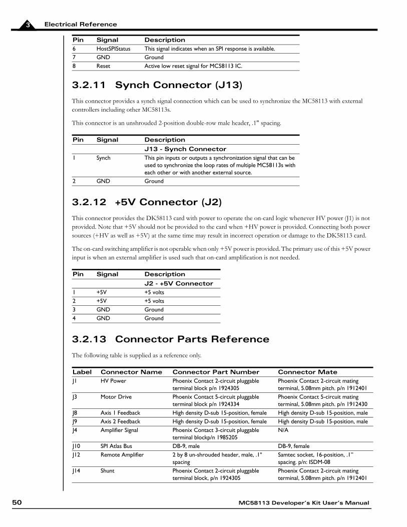
Electrical Reference3
3.2.11 Synch Connector (J13)
This connector provides a synch signal connection which can be used to synchronize the MC58113 with external controllers including other MC58113s.
This connector is an unshrouded 2-position double-row male header, .1" spacing.
3.2.12 +5V Connector (J2)
This connector provides the DK58113 card with power to operate the on-card logic whenever HV power (J1) is not provided. Note that +5V should not be provided to the card when +HV power is provided. Connecting both power sources (+HV as well as +5V) at the same time may result in incorrect operation or damage to the DK58113 card.
The on-card switching amplifier is not operable when only +5V power is provided. The primary use of this +5V power input is when an external amplifier is used such that on-card amplification is not needed.
3.2.13 Connector Parts Reference
The following table is supplied as a reference only.
6 HostSPIStatus This signal indicates when an SPI response is available.7 GND Ground8 Reset Active low reset signal for MC58113 IC.
Pin Signal DescriptionJ13 - Synch Connector
1 Synch This pin inputs or outputs a synchronization signal that can be used to synchronize the loop rates of multiple MC58113s with each other or with another external source.
2 GND Ground
Pin Signal DescriptionJ2 - +5V Connector
1 +5V +5 volts2 +5V +5 volts3 GND Ground4 GND Ground
Label Connector Name Connector Part Number Connector MateJ1 HV Power Phoenix Contact 2-circuit pluggable
terminal block p/n 1924305Phoenix Contact 2-circuit mating terminal, 5.08mm pitch. p/n 1912401
J3 Motor Drive Phoenix Contact 5-circuit pluggable terminal block p/n 1924334
Phoenix Contact 5-circuit mating terminal, 5.08mm pitch. p/n 1912430
J8 Axis 1 Feedback High density D-sub 15-position, female High density D-sub 15-position, maleJ9 Axis 2 Feedback High density D-sub 15-position, female High density D-sub 15-position, maleJ4 Amplifier Signal Phoenix Contact 3-circuit pluggable
terminal blockp/n 1985205N/A
J10 SPI Atlas Bus DB-9, male DB-9, femaleJ12 Remote Amplifier 2 by 8 un-shrouded header, male, .1"
spacingSamtec socket, 16-position, .1’’ spacing. p/n: ISDM-08
J14 Shunt Phoenix Contact 2-circuit pluggable terminal block, p/n 1924305
Phoenix Contact 2-circuit mating terminal, 5.08mm pitch. p/n 1912401
Pin Signal Description
50 MC58113 Developer’s Kit User’s Manual
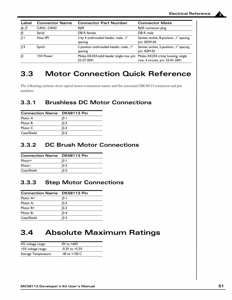
Electrical Reference 3
3.3 Motor Connection Quick Reference
The following sections show typical motor connection names and the associated DK58113 connector and pin numbers.
3.3.1 Brushless DC Motor Connections
3.3.2 DC Brush Motor Connections
3.3.3 Step Motor Connections
3.4 Absolute Maximum Ratings
J6, J7 CAN1, CAN2 RJ45 RJ45 connector plugJ5 Serial DB-9, female DB-9, maleJ11 Host SPI 2 by 4 unshrouded header, male, .1"
spacingSamtec socket, 8-position, .1’’ spacing. p/n: ISDM-04
J13 Synch 2 position unshrouded header, male, .1" spacing
Samtec socket, 2-position, .1’’ spacing. p/n: ISSM-02
J2 +5V Power Molex KK254 solid header single row, p/n 22-27-2041
Molex KK254 crimp housing, single row, 4 circuits. p/n: 22-01-2041
Connection Name DK58113 PinMotor A J3-1Motor B J3-2Motor C J3-3Case/Shield J3-5
Connection Name DK58113 PinMotor+ J3-1Motor- J3-3Case/Shield J3-5
Connection Name DK58113 PinMotor A+ J3-1Motor A- J3-2Motor B+ J3-3Motor B- J3-4Case/Shield J3-5
HV voltage range: 0V to +60V+5V voltage range: -0.3V to +5.5VStorage Temperature: -40 to +150 C
Label Connector Name Connector Part Number Connector Mate
MC58113 Developer’s Kit User’s Manual 51
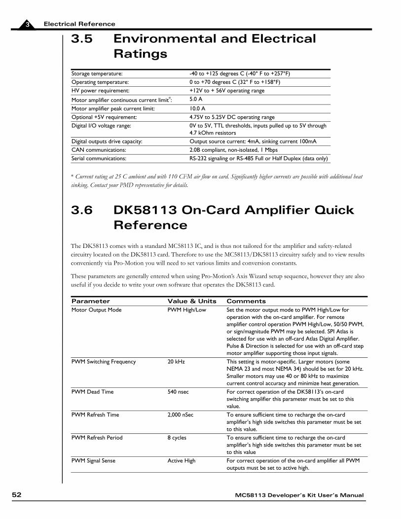
Electrical Reference3
3.5 Environmental and Electrical Ratings
* Current rating at 25 C ambient and with 110 CFM air flow on card. Significantly higher currents are possible with additional heat sinking. Contact your PMD representative for details.
3.6 DK58113 On-Card Amplifier Quick Reference
The DK58113 comes with a standard MC58113 IC, and is thus not tailored for the amplifier and safety-related circuitry located on the DK58113 card. Therefore to use the MC58113/DK58113 circuitry safely and to view results conveniently via Pro-Motion you will need to set various limits and conversion constants.
These parameters are generally entered when using Pro-Motion’s Axis Wizard setup sequence, however they are also useful if you decide to write your own software that operates the DK58113 card.
Storage temperature: -40 to +125 degrees C (-40° F to +257°F)Operating temperature: 0 to +70 degrees C (32° F to +158°F)HV power requirement: +12V to + 56V operating range
Motor amplifier continuous current limit*: 5.0 A
Motor amplifier peak current limit: 10.0 AOptional +5V requirement: 4.75V to 5.25V DC operating rangeDigital I/O voltage range: 0V to 5V, TTL thresholds, inputs pulled up to 5V through
4.7 kOhm resistorsDigital outputs drive capacity: Output source current: 4mA, sinking current 100mACAN communications: 2.0B compliant, non-isolated, 1 MbpsSerial communications: RS-232 signaling or RS-485 Full or Half Duplex (data only)
Parameter Value & Units CommentsMotor Output Mode PWM High/Low Set the motor output mode to PWM High/Low for
operation with the on-card amplifier. For remote amplifier control operation PWM High/Low, 50/50 PWM, or sign/magnitude PWM may be selected. SPI Atlas is selected for use with an off-card Atlas Digital Amplifier. Pulse & Direction is selected for use with an off-card step motor amplifier supporting those input signals.
PWM Switching Frequency 20 kHz This setting is motor-specific. Larger motors (some NEMA 23 and most NEMA 34) should be set for 20 kHz. Smaller motors may use 40 or 80 kHz to maximize current control accuracy and minimize heat generation.
PWM Dead Time 540 nsec For correct operation of the DK58113’s on-card switching amplifier this parameter must be set to this value.
PWM Refresh Time 2,000 nSec To ensure sufficient time to recharge the on-card amplifier’s high side switches this parameter must be set to this value.
PWM Refresh Period 8 cycles To ensure sufficient time to recharge the on-card amplifier’s high side switches this parameter must be set to this value
PWM Signal Sense Active High For correct operation of the on-card amplifier all PWM outputs must be set to active high.
52 MC58113 Developer’s Kit User’s Manual
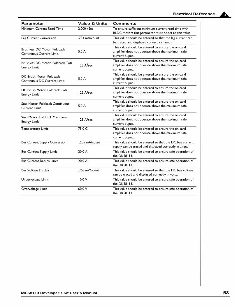
Electrical Reference 3
Minimum Current Read Time 2,000 nSec To ensure sufficient minimum current read time with BLDC motors this parameter must be set to this value.
Leg Current Conversion .733 mA/count This value should be entered so that the leg current can be traced and displayed correctly in amps.
Brushless DC Motor: Foldback Continuous Current Limit
5.0 AThis value should be entered to ensure the on-card amplifier does not operate above the maximum safe current ouput.
Brushless DC Motor: Foldback Total Energy Limit 125 A2sec
This value should be entered to ensure the on-card amplifier does not operate above the maximum safe current ouput.
DC Brush Motor: Foldback Continuous DC Current Limit
5.0 AThis value should be entered to ensure the on-card amplifier does not operate above the maximum safe current ouput.
DC Brush Motor: Foldback Total Energy Limit 125 A2sec
This value should be entered to ensure the on-card amplifier does not operate above the maximum safe current ouput.
Step Motor: Foldback Continuous Current Limit
5.0 AThis value should be entered to ensure the on-card amplifier does not operate above the maximum safe current ouput.
Step Motor: Foldback Maximum Energy Limit 125 A2sec
This value should be entered to ensure the on-card amplifier does not operate above the maximum safe current ouput.
Temperature Limit 75.0 C This value should be entered to ensure the on-card amplifier does not operate above the maximum safe current ouput.
Bus Current Supply Conversion .505 mA/count This value should be entered so that the DC bus current supply can be traced and displayed correctly in amps.
Bus Current Supply Limit 20.0 A This value should be entered to ensure safe operation of the DK58113.
Bus Current Return Limit 20.0 A This value should be entered to ensure safe operation of the DK58113.
Bus Voltage Display .966 mV/count This value should be entered so that the DC bus voltage can be traced and displayed correctly in volts.
Undervoltage Limit 10.0 V This value should be entered to ensure safe operation of the DK58113.
Overvoltage Limit 60.0 V This value should be entered to ensure safe operation of the DK58113.
Parameter Value & Units Comments
MC58113 Developer’s Kit User’s Manual 53

Electrical Reference3
This page intentionally left blank.
54 MC58113 Developer’s Kit User’s Manual
Index
Symbols/Enable and FaultOut Signals 40/Enable signal 40Numerics3-phase bridge 28
AAxisIn and AxisOut signals 39
BBlock Diagram 25brushless DC motors 22
Hall signals 38power stage configuration 28
Ccircuits
AxisIn 39AxisOut 39FaultOut 41Hall input 38limit and home input 38main encoder input 37, 38
Comm ports 26communication ports 26
RS-232/485 version 26communications
ports 26commutation 22
brushless DC motors 22commutation, sinusoidal 38components table, front of board 14configuration storage, on-IC NVRAM 42connections
communications 19motor power 19
connectorsfeedback 37
DDC brush motors
power stage configuration 28
DC buscurrent monitoring 34overvoltage and undervoltage 35
diagramsAxisIn circuit 39FaultOut circuit 41main encoder input circuits 38
differential encodersignals 37
Eencoder
incremental quadrature 37main 37
FFaultOut signal 40feedback connector 37
Gground fault 34
HHall signals 37, 38H-Bridge 28home inputs 38
II/O connector
signals 40I2t current foldback
energy limit 32incremental quadrature encoders 37inputs
Hall 38limit and home 38main encoder 37
Llimit inputs 38
MMagellan family 8
MC58113 Developer’s Kit User’s Manual 55
56
main encoder input circuits 38MOSFET power stages 28, 33Motor Feedback 37motor feedback 37
Nnetworking
configurations 26noise
R-C lowpass filter and 38
Ooperating temperature 33overtemperature protection 33
Pports, communication 26power
applying 19product summary 8PWM Power Stage 28
Qquadrature
incremental encoders 37
RR-C lowpass filter bandwidth
/Enable and FaultOut signals 40Hall inputs 38limit and home inputs 38
RS-232/485 connectorcommunication ports 26
Ssafety interlocks 40signals
/Enable 40AxisIn and AxisOut 39FaultOut 40single-ended 37
sinusoidal commutation 38SPI bus 33step motors
power stage configuration 28synch I/O
connectors 41synchronizing multiple boards 41
Ttemperature sensors 33
Uundervoltage, condition and threshold 35user-settable components 43
MC58113 Developer’s Kit User’s Manual

For additional information, or for technical assistance,please contact PMD at (978) 266-1210.
You may also e-mail your request to [email protected]
Visit our website at http://www.pmdcorp.com
Performance Motion Devices55 Old Bedford Rd.Lincoln, MA 01773
MC58113 Developer’s Kit User’s Manual 57

1
This page intentionally left blank.
58 MC58113 Developer’s Kit User’s Manual


![[PPT]Ferdinand Magellan - Tripod.comwadd.tripod.com/Magellan.ppt · Web viewFerdinand Magellan By Taylor and Haley Magellan was born in spring in 1470. Magellan was killed in the](https://img.pdfslide.us/doc/110x75/5afc89fd7f8b9a814d8c3915/pptferdinand-magellan-viewferdinand-magellan-by-taylor-and-haley-magellan-was.jpg)