Embed Size (px)
Citation preview
®
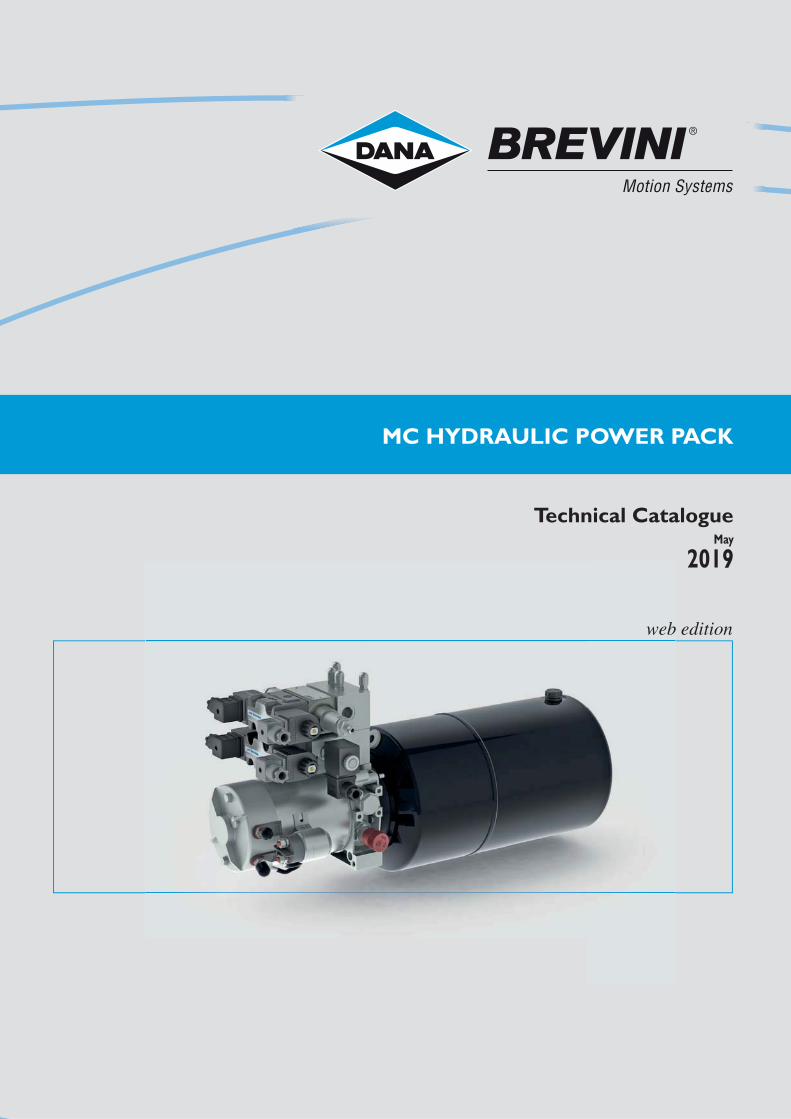
MC HYDRAULIC POWER PACK
Technical CatalogueMay
2019
web edition


1IE/MC-INTRO/00-2017
i
Table of contents
Introduction ...................................................................................................... 2
Endhead configuration .................................................................................... 3
Power pack sections ...................................................................................... 5
Selection code ................................................................................................. 6
Endhead overall dimensions ......................................................................... 9
Cavities dimensions ...................................................................................... 10
SELECTIONS FOR “MCA-MCB” POWER PACK ENDHEAD Endhead choice ............................................................................................. 11
Sect. I - MC Cavity 1 ...................................................................................... 12
Sect. I - MC Cavity 1R .................................................................................... 13
Sect. II - MC Cavity 2 ..................................................................................... 14
Sect. II - MCA Cavity 3 .................................................................................. 17
Sect. II - MCB Cavity 3 .................................................................................. 20
Sect. II - MCA Cavity 4 .................................................................................. 21
Sect. II - MC Ports P-T .................................................................................. 22
SELECTIONS FOR ALL POWER PACK ENDHEADS Sect. III - Pumps ............................................................................................. 23
Sect. IV - Tanks / Sect. V - Tubes kit .......................................................... 25
Sect. VI - DC Motors ...................................................................................... 41
Sect. VI - AC Motors ...................................................................................... 47
Sect. VII - Transmission kit DC motors ...................................................... 53
Sect. VIII - Blocks and CETOP valves ........................................................ 55
Sect. IX - Accessories .................................................................................. 59
Examples ......................................................................................................... 60
© 2019 Dana Motion Systems Italia S.r.l. all rights reserved. Hydr-App, SAM Hydraulik, Aron, Brevini Hydraulics, BPE Electronics, VPS Brevini, OT Oiltechno-logy, logos are trademarks or are registered trademarks of Dana Motion Systems Italia S.r.l. or other companies Dana in Italy and other countries.
The technical features supplied in this catalogue are non binding and no legal action can be taken against such material. Dana will not be held responsible for information and specifications which may lead to error or incorrect interpretations. Given the continuous technical research aimed at improved technical features of our products, Dana reserves the right to make change that are considered appropriate without any prior notice. This catalogue cannot be reproduced (in while or in part) without the prior written consent of Dana. This catalogue supersedes all previous ones.
Use of the products in this catalogue must comply with the operating limits given in the technical specifications. The type of application and operating condi-tions must be assessed as normal or in malfunction in order to avoid endangering the safety of people and/or items.
®
2 IE/MC-INTRO/00-2017
i
*
M
OIL
82
M10
P T
PT
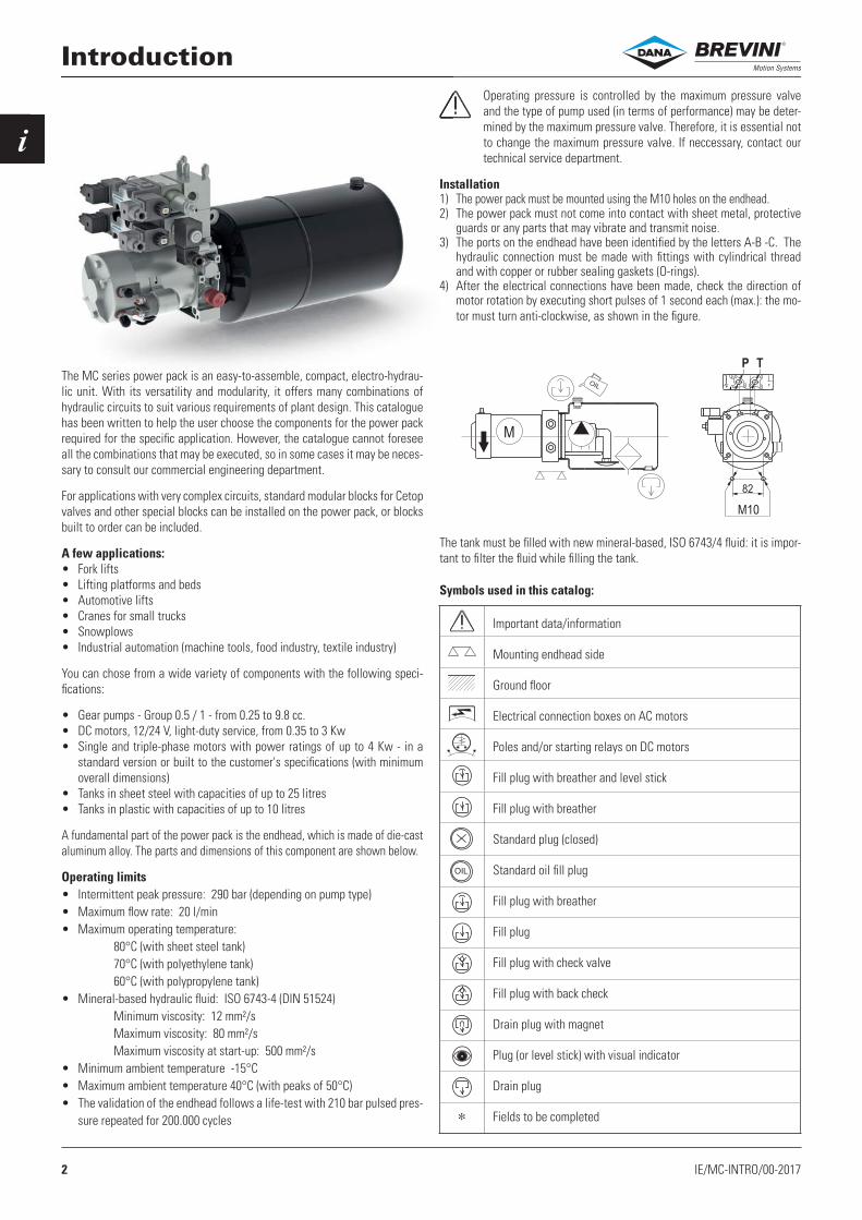
Introduction
The MC series power pack is an easy-to-assemble, compact, electro-hydrau-lic unit. With its versatility and modularity, it offers many combinations of hydraulic circuits to suit various requirements of plant design. This catalogue has been written to help the user choose the components for the power pack required for the specifi c application. However, the catalogue cannot foresee all the combinations that may be executed, so in some cases it may be neces-sary to consult our commercial engineering department.
For applications with very complex circuits, standard modular blocks for Cetop valves and other special blocks can be installed on the power pack, or blocks built to order can be included.
A few applications:• Fork lifts• Lifting platforms and beds• Automotive lifts• Cranes for small trucks• Snowplows• Industrial automation (machine tools, food industry, textile industry)
You can chose from a wide variety of components with the following speci-fi cations:
• Gear pumps - Group 0.5 / 1 - from 0.25 to 9.8 cc.• DC motors, 12/24 V, light-duty service, from 0.35 to 3 Kw• Single and triple-phase motors with power ratings of up to 4 Kw - in a
standard version or built to the customer's specifi cations (with minimum overall dimensions)
• Tanks in sheet steel with capacities of up to 25 litres• Tanks in plastic with capacities of up to 10 litres
A fundamental part of the power pack is the endhead, which is made of die-cast aluminum alloy. The parts and dimensions of this component are shown below.
Operating limits• Intermittent peak pressure: 290 bar (depending on pump type)• Maximum fl ow rate: 20 l/min• Maximum operating temperature: 80°C (with sheet steel tank) 70°C (with polyethylene tank) 60°C (with polypropylene tank)• Mineral-based hydraulic fl uid: ISO 6743-4 (DIN 51524) Minimum viscosity: 12 mm²/s Maximum viscosity: 80 mm²/s Maximum viscosity at start-up: 500 mm²/s• Minimum ambient temperature -15°C• Maximum ambient temperature 40°C (with peaks of 50°C)• The validation of the endhead follows a life-test with 210 bar pulsed pres-
sure repeated for 200.000 cycles
Important data/information
Mounting endhead side
Ground fl oor
Electrical connection boxes on AC motors
Poles and/or starting relays on DC motors
Fill plug with breather and level stick
Fill plug with breather
Standard plug (closed)
Standard oil fi ll plug
Fill plug with breather
Fill plug
Fill plug with check valve
Fill plug with back check
Drain plug with magnet
Plug (or level stick) with visual indicator
Drain plug
Fields to be completed
Operating pressure is controlled by the maximum pressure valve and the type of pump used (in terms of performance) may be deter-mined by the maximum pressure valve. Therefore, it is essential not to change the maximum pressure valve. If neccessary, contact our technical service department.
Installation1) The power pack must be mounted using the M10 holes on the endhead.2) The power pack must not come into contact with sheet metal, protective
guards or any parts that may vibrate and transmit noise.3) The ports on the endhead have been identifi ed by the letters A-B -C. The
hydraulic connection must be made with fi ttings with cylindrical thread and with copper or rubber sealing gaskets (O-rings).
4) After the electrical connections have been made, check the direction of motor rotation by executing short pulses of 1 second each (max.): the mo-tor must turn anti-clockwise, as shown in the fi gure.
The tank must be fi lled with new mineral-based, ISO 6743/4 fl uid: it is impor-tant to fi lter the fl uid while fi lling the tank.
Symbols used in this catalog:
®
3IE/MC-INTRO/00-2017
i
T1
3FC*
3TN
3HC
3TR
3TS
3FBC
3LB
3TQ
3CB
A1-B1-C1-D1
A2-B2
C2-D2
A3-B3
C3-D3
3CA
3FD*
3TP
1
3
4
1
3
A-B
2CA
2DB*
2FAA
2FAB
2TD
2TK
X
2DA*
2DD*
2HA
2TC
2TF
C
2CB
2DC*
2TA
2TE
1
R
2
1R
4
T P
2
4TB/*
3/4-16 unf
M16 x 1.5M18 x 1.5
M20 x 1.5
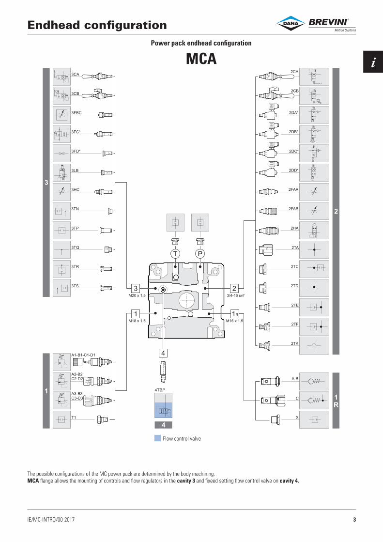
Endhead configurationPower pack endhead configuration
MCA
Flow control valve
The possible configurations of the MC power pack are determined by the body machining.MCA flange allows the mounting of controls and flow regulators in the cavity 3 and fixeed setting flow control valve on cavity 4.
®

4 IE/MC-INTRO/00-2017
i
3TJ/*3
1
3
A-B
2CA
2DB*
2FAA
2FAB
2TD
2TK
X
2DA*
2DD*
2HA
2TC
2TF
C
2CB
2DC*
2TA
2TE
1
R
2
1R
T P
23/4-16 unf
M16 x 1.5M18 x 1.5
M20 x 1.5
T1
A2-B2
C2-D2
A3-B3
C3-D3
1
A1-B1-C1-D1
Endhead configurationPower pack endhead configuration
MCB
The possible configurations of the MC power pack are determined by the body machining.MCA flange allows the mounting of controls and flow regulators fixed setting in the cavity 3.
®
5IE/MC-INTRO/00-2017
i
V (G)
VI (M)
VII (T)
VIII (J-K-W)
II
II
MCA
IV (S)
I
III (P)
IX (R)
MCB
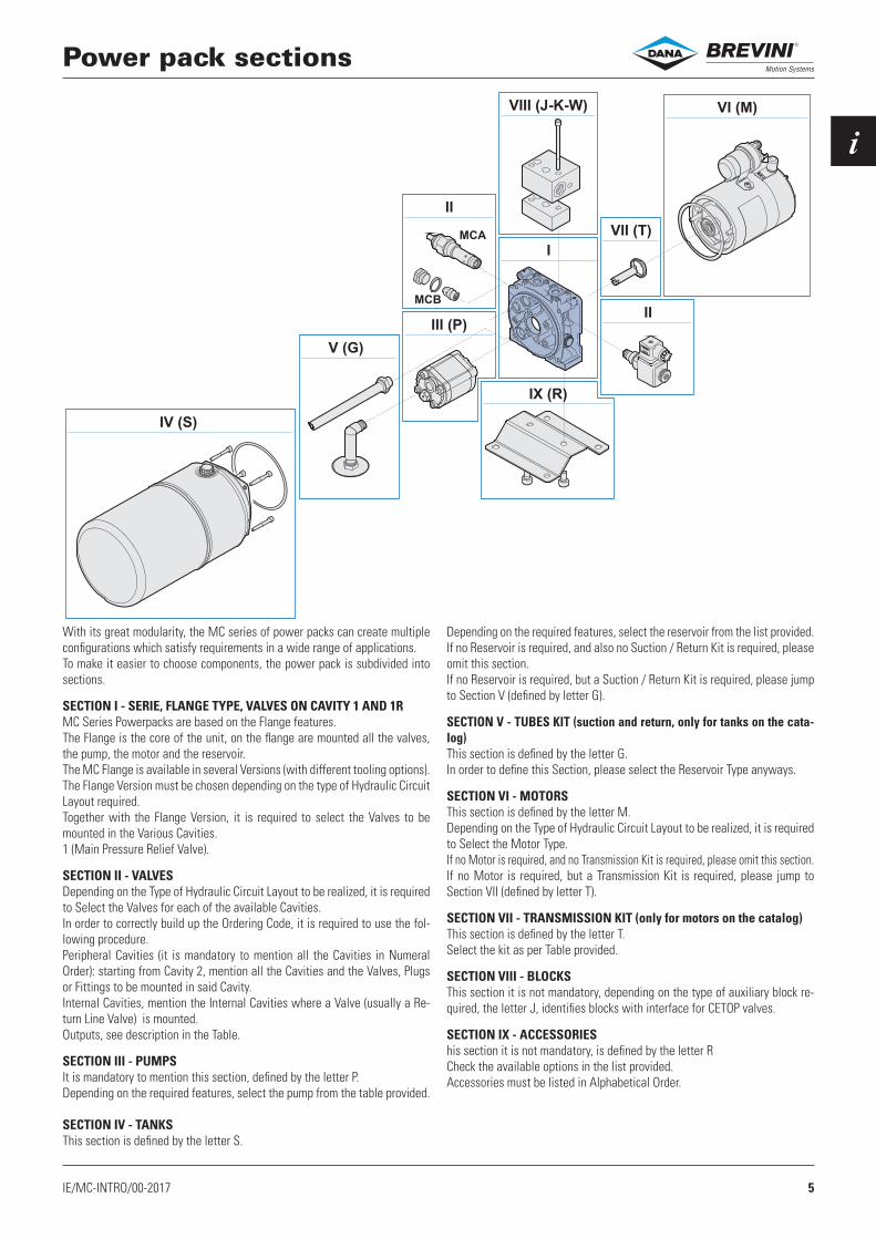
Power pack sections
With its great modularity, the MC series of power packs can create multiple configurations which satisfy requirements in a wide range of applications.To make it easier to choose components, the power pack is subdivided into sections.
SECTION I - SERIE, FLANGE TYPE, VALVES ON CAVITY 1 AND 1RMC Series Powerpacks are based on the Flange features.The Flange is the core of the unit, on the flange are mounted all the valves, the pump, the motor and the reservoir.The MC Flange is available in several Versions (with different tooling options).The Flange Version must be chosen depending on the type of Hydraulic Circuit Layout required.Together with the Flange Version, it is required to select the Valves to be mounted in the Various Cavities.1 (Main Pressure Relief Valve).
SECTION II - VALVESDepending on the Type of Hydraulic Circuit Layout to be realized, it is required to Select the Valves for each of the available Cavities.In order to correctly build up the Ordering Code, it is required to use the fol-lowing procedure.Peripheral Cavities (it is mandatory to mention all the Cavities in Numeral Order): starting from Cavity 2, mention all the Cavities and the Valves, Plugs or Fittings to be mounted in said Cavity.Internal Cavities, mention the Internal Cavities where a Valve (usually a Re-turn Line Valve) is mounted.Outputs, see description in the Table.
SECTION III - PUMPSIt is mandatory to mention this section, defined by the letter P.Depending on the required features, select the pump from the table provided.
SECTION IV - TANKSThis section is defined by the letter S.
Depending on the required features, select the reservoir from the list provided.If no Reservoir is required, and also no Suction / Return Kit is required, please omit this section.If no Reservoir is required, but a Suction / Return Kit is required, please jump to Section V (defined by letter G).
SECTION V - TUBES KIT (suction and return, only for tanks on the cata-log)This section is defined by the letter G.In order to define this Section, please select the Reservoir Type anyways.
SECTION VI - MOTORSThis section is defined by the letter M.Depending on the Type of Hydraulic Circuit Layout to be realized, it is required to Select the Motor Type.If no Motor is required, and no Transmission Kit is required, please omit this section.If no Motor is required, but a Transmission Kit is required, please jump to Section VII (defined by letter T).
SECTION VII - TRANSMISSION KIT (only for motors on the catalog)This section is defined by the letter T.Select the kit as per Table provided.
SECTION VIII - BLOCKSThis section it is not mandatory, depending on the type of auxiliary block re-quired, the letter J, identifies blocks with interface for CETOP valves.
SECTION IX - ACCESSORIEShis section it is not mandatory, is defined by the letter RCheck the available options in the list provided.Accessories must be listed in Alphabetical Order.
®
6 IE/MC-INTRO/00-2017
i
P * (*) ** / * -
2 .. ** 3 .. ** /* 4 .. /* -** -
MC * * * * (...)
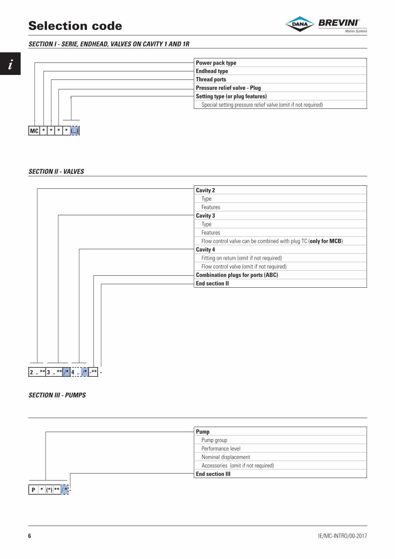
Selection codeSECTION I - SERIE, ENDHEAD, VALVES ON CAVITY 1 AND 1R
SECTION II - VALVES
SECTION III - PUMPS
Power pack typeEndhead typeThread portsPressure relief valve - PlugSetting type (or plug features)
Special setting pressure relief valve (omit if not required)
Cavity 2TypeFeatures
Cavity 3TypeFeaturesFlow control valve can be combined with plug TC (only for MCB)
Cavity 4Fitting on return (omit if not required)Flow control valve (omit if not required)
Combination plugs for ports (ABC)End section II
PumpPump groupPerformance levelNominal displacementAccessories (omit if not required)
End section III
®
7IE/MC-INTRO/00-2017
i
* ** * (*) ** /* -
M * ** (*) * /* -
M * * * * (*) /* -
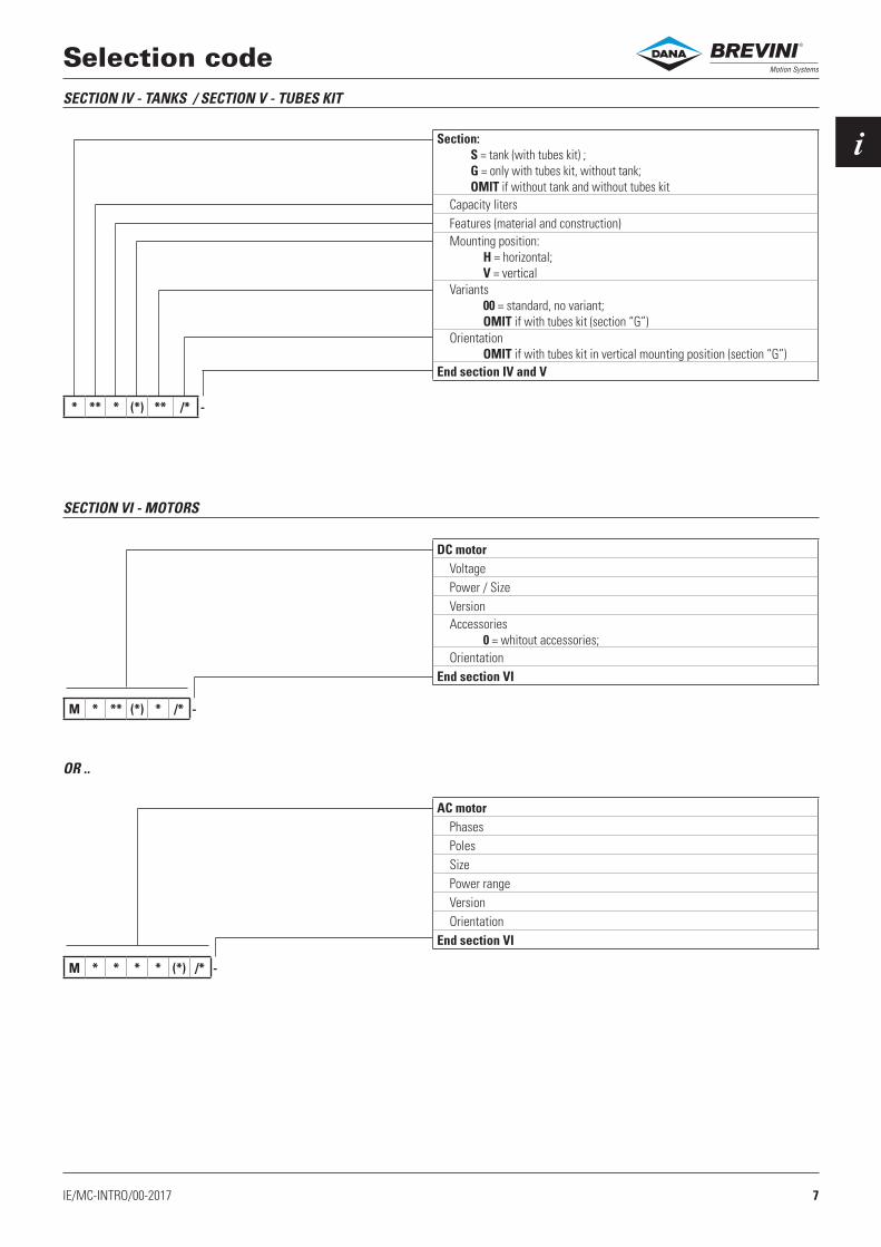
Selection codeSECTION IV - TANKS / SECTION V - TUBES KIT
SECTION VI - MOTORS
DC motorVoltagePower / SizeVersionAccessories 0 = whitout accessories; Orientation
End section VI
Section: S = tank (with tubes kit) ; G = only with tubes kit, without tank; OMIT if without tank and without tubes kit
Capacity litersFeatures (material and construction)Mounting position: H = horizontal; V = verticalVariants 00 = standard, no variant; OMIT if with tubes kit (section “G”)Orientation OMIT if with tubes kit in vertical mounting position (section “G”)
End section IV and V
AC motorPhasesPolesSizePower rangeVersionOrientation
End section VI
OR ..
®

8 IE/MC-INTRO/00-2017
i
T ** -
R * *
J * (00) - ** (00) (..) (..) /***/ -
Selection codeSECTION VII - TRANSMISSION KIT (only for motors on the catalog)
SECTION VIII - BLOCKS
Transmission kitType
End section VII
Specify the transmission kit whether you requested the joint and acces-sories assembly (without motor).
BlocksMounting positionAccessory
Separation lineBlock typeAccessoryPressure relief valve setting on “A” linePressure relief valve setting on “B” lineCETOP valve
End section VIII
Accessories (optional)First accessorySecond accessory
SECTION IX - ACCESSORIES
®

9IE/MC-INTRO/00-2017
i
118
101.6
118
134
101.6
82
20
20
118
118
G3/8" BSP40
42,50
46
11
20°
Ø27
Ø32
Ø121
Ø35
Ø80
Ø110
Ø98.3
14.1 10
4
PT
P MCA
MCB
T
S
2 3
1R 1
54
Endhead overall dimensions
POWER PACK FIXING SIDE
2 HO
LES
M10
(18)
4 HO
LES
WIT
H Ø7
(FOR
ATT
ACHI
NG
TAN
KS)
PUMP/TANK SIDE
PORT SIDE
On the endhead are highlighted (P-T) ports. In the drawing are shown the common dimensions.
GROOVE FOR TANKSEALING GASKET(O-RING, 3.53x110.72)
2 - M6 HOLES (10) WITH CENTER DISTANCE OF 101.5
MOTOR SIDE
4 HO
LES
1/4-
20 U
NC
(12)
W
ITH
CEN
TER
DIST
ANCE
OF
91
4 HOLES M8
The number of cavities tooled identify the endhead type:
There are three types of cavities:- Peripheral cavities, which can be accessed externally - Return cavities, inside of the tank.- Ports
Cavity ThreadEndhead typeMCA MCB
PT Ports
G1/4” • (1) • (1)
G3/8” • •
7/16” 20 UNF • •
9/16” 18 UNF • •
1 Peripheral M18 x 1.5 • •
1R Peripheral M16 x 1.5 • •
2 Peripheral 3/4” 16 UNF • •
3 Peripheral M20 x 1.5 • • (2)
4 Primaryreturn G3/8” • •
5 Secondary return
Ø 14not thread • •
S Press. reliefvalve return
Ø 12,5not thread • •
Cavities on endhead:
Cavity 3 detail
1) blocks interface
2) end cavity tooled G3/8” for flow regulator VSC06
3) return from T (ex. blocks)
®

10 IE/MC-INTRO/00-2017
i
CN041007
1C
1P
CN037004
3A
Ø 1
3
Ø.
14
5
3 7.
29
37
M16x1.5
16 5.
Ø 2
9
24,2
Ø9
Ø 1
4
26
40
2,5
16
13
12
Mx
18
1.5
Ø 3
4
3/4
" 16 U
NF
Ø20.6
Ø9
20
13
2.5
14.5
30
55.5
41.5
15
3
Ø 2
8
Ø 1
6
Ø 1
8.5
M2
0x1
.5M
20x1.5
55.5
15
29
40.5 10
Ø15.5
G3/8
"
Cavities dimensionsCavity Thread Drawing
1 Peripheral M18 x 1.5
1R Peripheral M16 x 1.5
2 Peripheral 3/4 16 UNF
3MCA Peripheral M20 x 1.5
3MCB Peripheral M20 x 1.5
®

11IE/MC-2/00-2017
IMC * *
3
T P
*
*
Endhead choice
The machining of the cavity 3 and the P-T ports define the body type.
Endhead typeThread ports
* Description
A For manual controls, flow regulators, logic valves on cavity 3 (Old commercial description MC)
B For flow regulator VSC06 (3/8” BSP) on cavity 3 (Old commercial description MS)
Endhead type
Thread ports P-T”
*Ports thread Blocks
interfaceG1/4” G3/8” 9/16” 18 UNF 7/16” 20 UNF
0 YES YES
1 YES NO
2 YES NO
3 YES NO
Endhead codesG1/4” G3/8” 7/16” 20 UNF 9/16” 18 UNF
MCA 71013000.000 71013001.000 — 71013022.000
MCB 71013003.000 71013005.000 71013007.000 —
®
12 IE/MC-2/02-2019
II
* * (...)
* *
3 2
1R
4
1
T P
MC * * * * (...)
1
2
3
3
1
T1
A1
B1
C1
D1
A2
B2
C2
D2
A3
B3
C3
D3
2
T P
1R
4
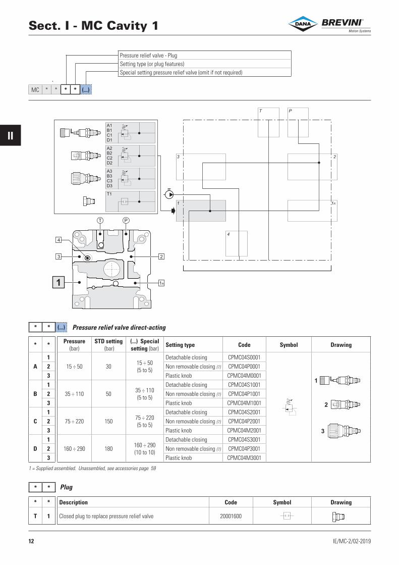
Sect. I - MC Cavity 1
Pressure relief valve - PlugSetting type (or plug features)Special setting pressure relief valve (omit if not required)
* * Description Code Symbol Drawing
T 1 Closed plug to replace pressure relief valve 20001600
Pressure relief valve direct-acting
Plug
1 = Supplied assembled. Unassembled, see accessories page 59
* * Pressure (bar)
STD setting (bar)
(...) Special setting (bar) Setting type Code Symbol Drawing
A1
15 ÷ 50 30 15 ÷ 50 (5 to 5)
Detachable closing CPMC04S0001
2 Non removable closing (1) CPMC04P0001
3 Plastic knob CPMC04M0001
B1
35 ÷ 110 50 35 ÷ 110 (5 to 5)
Detachable closing CPMC04S1001
2 Non removable closing (1) CPMC04P1001
3 Plastic knob CPMC04M1001
C1
75 ÷ 220 150 75 ÷ 220(5 to 5)
Detachable closing CPMC04S2001
2 Non removable closing (1) CPMC04P2001
3 Plastic knob CPMC04M2001
D1
160 ÷ 290 180 160 ÷ 290(10 to 10)
Detachable closing CPMC04S3001
2 Non removable closing (1) CPMC04P3001
3 Plastic knob CPMC04M3001
®
13IE/MC-2/02-2019
II
3 2
T P
X
C
A
B
4
3/8" BSP
1 1R
MC * * * * (...) *
T P
3 2
4
1 1R
*
*
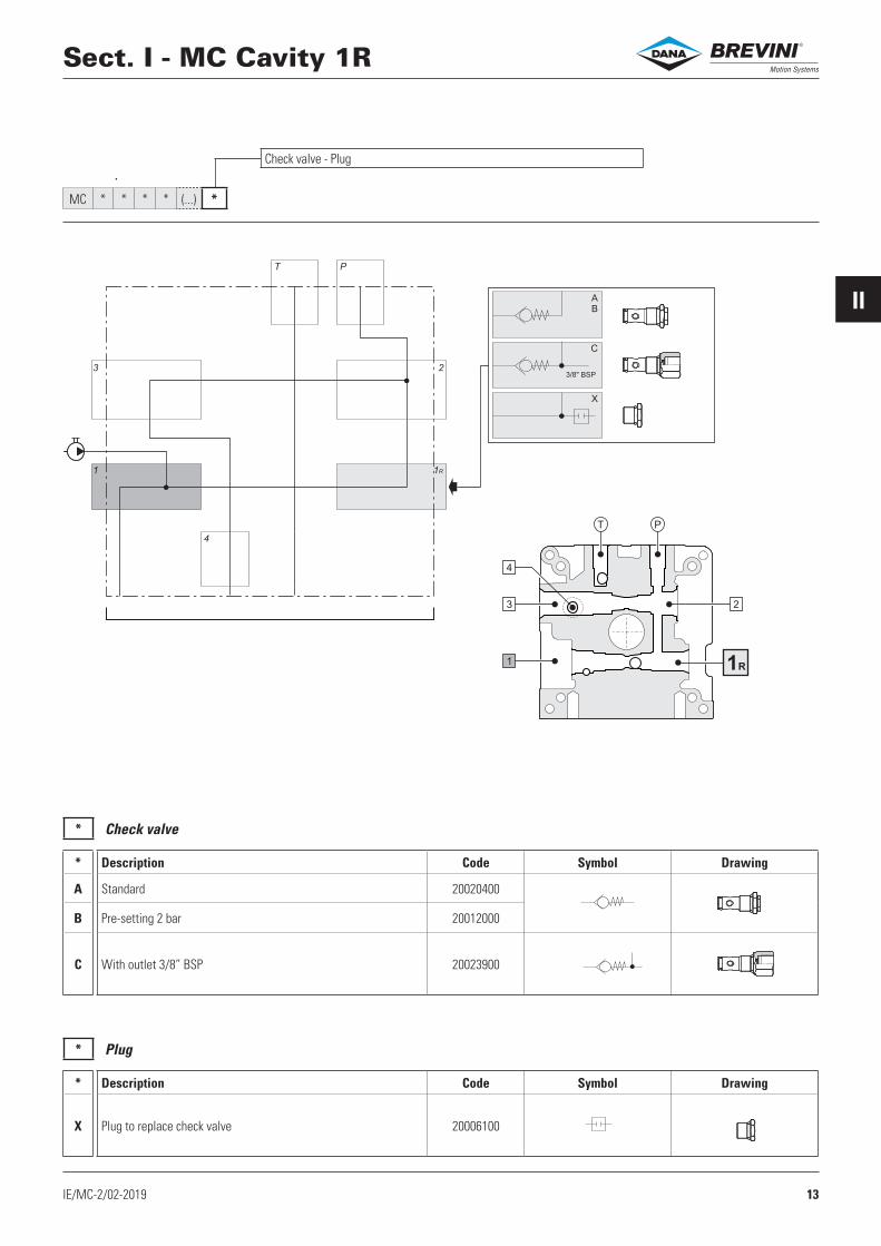
Sect. I - MC Cavity 1R
Check valve - Plug
* Description Code Symbol Drawing
A Standard 20020400
B Pre-setting 2 bar 20012000
C With outlet 3/8” BSP 20023900
Check valve
* Description Code Symbol Drawing
X Plug to replace check valve 20006100
Plug
®

14 IE/MC-2/02-2019
II
MC * * * * (...) * * * *
3 2
T P
4
2CA
2CB
2DA**
2DB**
2DC**
2DD**
2TC
2FA*
2TD
2TE
2HA
2TF
2TK
G 1/4"
2TA
G 1/4"
G 1/4"
G 1/4"
1 1R
T P
3
1R
4
1
2
Sect. II - MC Cavity 2CavityTypeFeatures
®
15IE/MC-2/02-2019
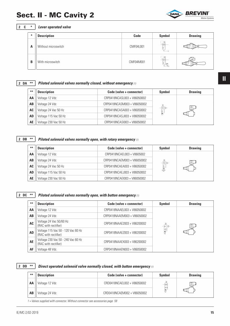
II2 DA **
2 DB **
2 DC **
2 DD **
2 C *
Sect. II - MC Cavity 2
** Description Code (valve + connector) Symbol Drawing
AA Voltage 12 Vdc CRP0418NCASL003 + V86050002
AB Voltage 24 Vdc CRP0418NCASM003 + V86050002
AC Voltage 24 Vac 50 Hz CRP0418NCASA003 + V86050002
AD Voltage 115 Vac 50 Hz CRP0418NCASJ003 + V86050002
AE Voltage 230 Vac 50 Hz CRP0418NCASI003 + V86050002
** Description Code (valve + connector) Symbol Drawing
AA Voltage 12 Vdc CRP0418NCAEL003 + V8605002
AB Voltage 24 Vdc CRP0418NCAEM003 + V86050002
AC Voltage 24 Vac 50 Hz CRP0418NCAEA003 + V86050002
AD Voltage 115 Vac 50 Hz CRP0418NCAEJ003 + V86050002
AE Voltage 230 Vac 50 Hz CRP0418NCAEI003 + V86050002
** Description Code (valve + connector) Symbol Drawing
AA Voltage 12 Vdc CRP0418NAAEL003 + V86050002
AB Voltage 24 Vdc CRP0418NAAEM003 + V86050002
AC Voltage 24 Vac 50/60 Hz (RAC with rectifier) CRP0418NAAE2003 + V86200002
AD Voltage 115 Vac 50 - 120 Vac 60 Hz (RAC with rectifier) CRP0418NAAEZ003 + V86200002
AE Voltage 230 Vac 50 - 240 Vac 60 Hz (RAC with rectifier) CRP0418NAAEX003 + V86200002
AF Voltage 48 Vdc CRP0418NAAEN003 + V86050002
** Description Code (valve + connector) Symbol Drawing
AA Voltage 12 Vdc CRD0418NCAEL002 + V86050002
AB Voltage 24 Vdc CRD0418NCAEM002 + V86050002
* Description Code Symbol Drawing
A Without microswitch CMF04L001
B With microswitch CMF04M001
Piloted solenoid valves normally closed, without emergency (1)
Piloted solenoid valves normally open, with rotary emergency (1)
Piloted solenoid valves normally open, with button emergency (1)
Direct operated solenoid valve normally closed, with button emergency (1)
Lever operated valve
1 = Valves supplied with connector. Without connector see accessories page 59
®
16 IE/MC-2/02-2019
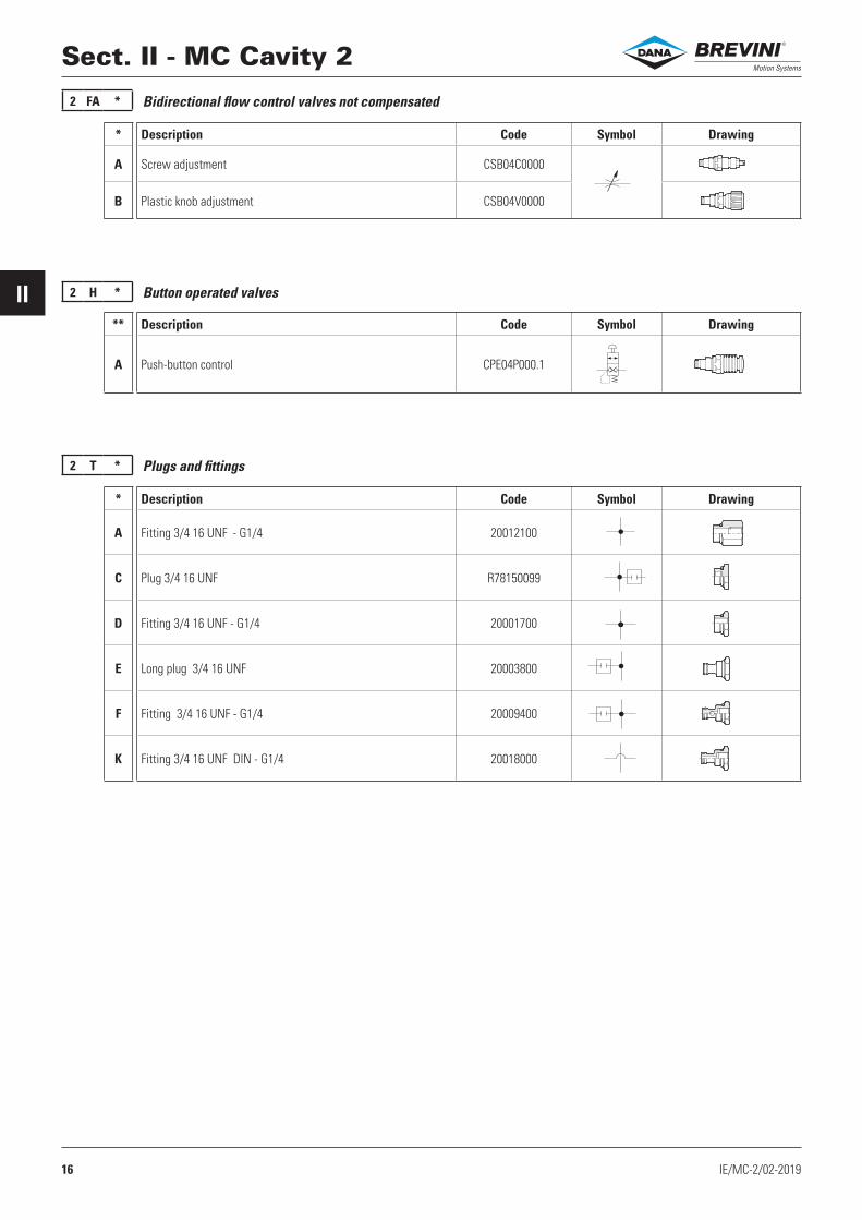
II 2 H *
2 FA *
2 T *
Sect. II - MC Cavity 2
** Description Code Symbol Drawing
A Push-button control CPE04P000.1
* Description Code Symbol Drawing
A Screw adjustment CSB04C0000
B Plastic knob adjustment CSB04V0000
* Description Code Symbol Drawing
A Fitting 3/4 16 UNF - G1/4 20012100
C Plug 3/4 16 UNF R78150099
D Fitting 3/4 16 UNF - G1/4 20001700
E Long plug 3/4 16 UNF 20003800
F Fitting 3/4 16 UNF - G1/4 20009400
K Fitting 3/4 16 UNF DIN - G1/4 20018000
Bidirectional flow control valves not compensated
Button operated valves
Plugs and fittings
®

17IE/MCA-2/01-2017
IIMCA
T P
2
1R
4
1
3
MC A * * * (...) * * * * * * *
3
3CA
3CB
3FBC
3FC*
3FD*
3LB
3HC
3TN
3TP
3TQ
3TR
3TS
2
T P
4G1/4"
G1/4"
U
U
1 1R
G 3/8"
G 1/4"
G 1/4"
Sect. II - MCA Cavity 3CavityTypeFeatures
Components only for MCA
®
18 IE/MCA-2/01-2017
IIMCA
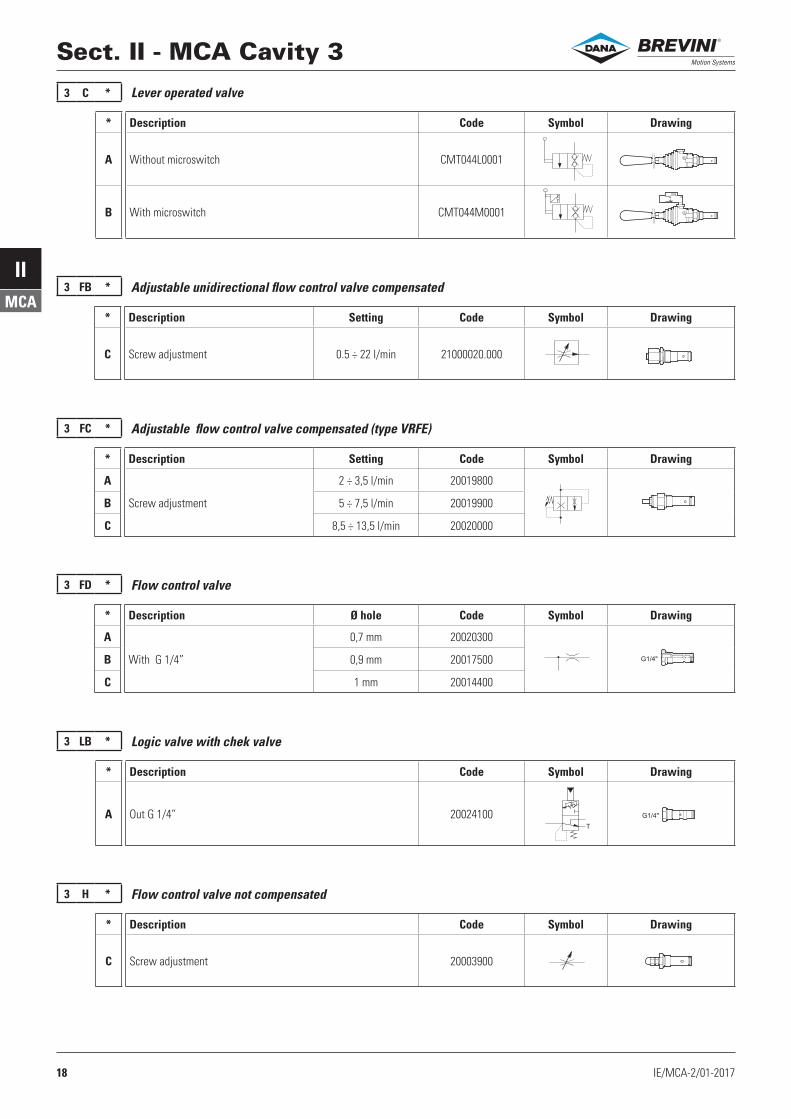
3 C *
3 FB *
3 FC *
3 FD *
3 H *
G1/4"
G1/4"
T
Sect. II - MCA Cavity 3
* Description Code Symbol Drawing
A Without microswitch CMT044L0001
B With microswitch CMT044M0001
Lever operated valve
Adjustable unidirectional flow control valve compensated
* Description Setting Code Symbol Drawing
A
Screw adjustment
2 ÷ 3,5 l/min 20019800
B 5 ÷ 7,5 l/min 20019900
C 8,5 ÷ 13,5 l/min 20020000
Adjustable flow control valve compensated (type VRFE)
* Description Ø hole Code Symbol Drawing
A
With G 1/4”
0,7 mm 20020300
B 0,9 mm 20017500
C 1 mm 20014400
Flow control valve
* Description Code Symbol Drawing
C Screw adjustment 20003900
Flow control valve not compensated
3 LB *
* Description Code Symbol Drawing
A Out G 1/4” 20024100
Logic valve with chek valve
* Description Setting Code Symbol Drawing
C Screw adjustment 0.5 ÷ 22 l/min 21000020.000
®
19IE/MCA-2/01-2017
IIMCA
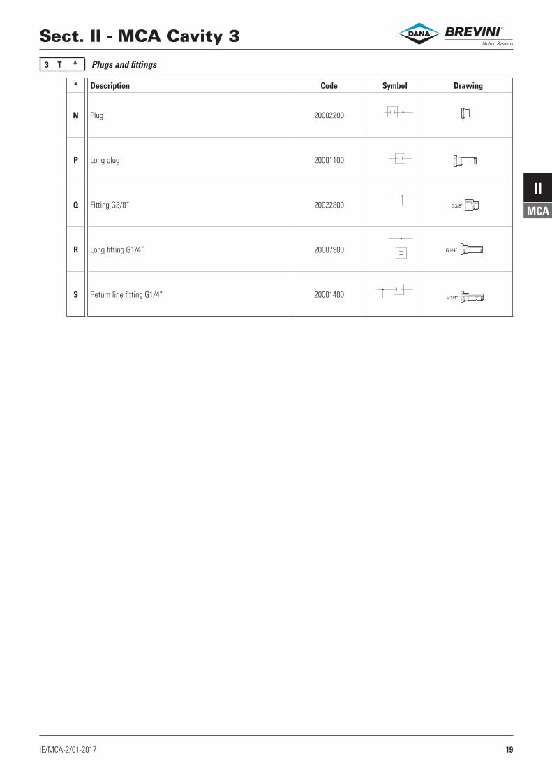
3 T *
G3/8"
G1/4"
G1/4"
Sect. II - MCA Cavity 3
* Description Code Symbol Drawing
N Plug 20002200
P Long plug 20001100
Q Fitting G3/8” 20022800
R Long fitting G1/4” 20007900
S Return line fitting G1/4” 20001400
Plugs and fittings
®

20 IE/MCB-2/01-2017
IIMCB
3 2
T P
4
1 1R
3TJ /*
T P
2
1R
4
1
3
3 TJ /*
MC B * * * (...) * * * * * * * / *
Sect. II - MCB Cavity 3
/* Flow Code (flow control valve) Code (kit plug + washer) Simbol Drawing
/A 0.7 l/min VSC06100002
17010085
/B 1.1 l/min VSC06120002
/C 2.1 l/min VSC06130002
/E 3.2 l/min VSC06150002
/G 4.7 l/min VSC06190002
/K 6.3 l/min VSC06220002
/N 7.5 l/min VSC06240002
/Q 10.0 l/min VSC06280002
/U 13.2 l/min VSC06330002
/V 15.7 l/min VSC06350002
Plug with flow control valve
Flow control valve
CavityTypeFeaturesFlow control valvesComponents only for MCB
®

21IE/MCA-2/01-2017
IIMCA
3 2
T P
4
4TB
/*
1 1R
MC A * * * (...) * * * * * * * / * 4TB /*
4 TB /*
T P
3 2
1R1
4
Componenti solo per MCA
Sect. II - MCA Cavity 4
Omit if not requiredComponents only for MCA
Any fitting and flow control valve on cavity 4
Fitting on return cavity 4Flow control valve on fitting 4
/* Flow Code (flow control valve)
Code (fitting for flow control valve) Simbol Drawing
/A 0.7 l/min VSC06100002
M67250053
/B 1.1 l/min VSC06120002
/C 2.1 l/min VSC06130002
/E 3.2 l/min VSC06150002
/G 4.7 l/min VSC06190002
/K 6.3 l/min VSC06220002
/N 7.5 l/min VSC06240002
/Q 10.0 l/min VSC06280002
/U 13.2 l/min VSC06330002
/V 15.7 l/min VSC06350002
Fitting and flow control valve
®
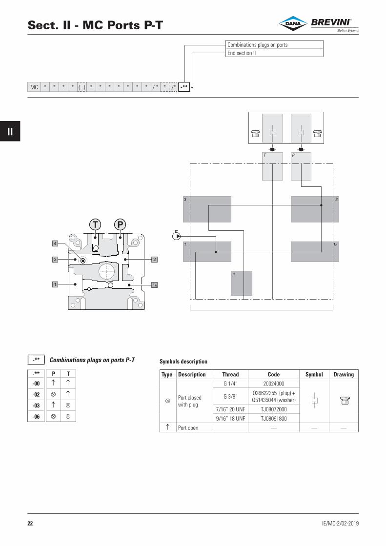
22 IE/MC-2/02-2019
II
-**
-** P T
-00
-02
-03
-06
3 2
T P
4
1 1R
3 2
1R
4
1
T P
MC * * * * (...) * * * * * * * / * * /* -** -
Sect. II - MC Ports P-T
Combinations plugs on ports P-T Symbols description
Combinations plugs on portsEnd section II
Type Description Thread Code Symbol Drawing
Port closed with plug
G 1/4” 20024000
G 3/8” Q26622255 (plug) + Q51435044 (washer)
7/16” 20 UNF TJ08072000
9/16” 18 UNF TJ08091800
Port open — — —
®

23IE/MC-3/00-2017
III
MC ........ P * (*) ** / * -
G1/4
Ø 2
2
Ø 3
2
14
L1
5P 0 (1) **
P 1 (1) ** / *
L1
G3/8
Ø 3
2
5
Sect. III - PumpsPumpPump groupPerformance levelNominal displacementAccessories (omit if not required)End section III
Pumps group 05 - Performance level 1
P2 = Intermittent operating pressure
P3 = Intermittent peak pressure (20 sec. max)
Tanks not compatible (as dimensions, see page 25)
Motors not compatible (interface and transmission not supplied, see
pages 41 - 47)
** Nominal displacement
Tolerance on geometric
displacement
P2bar
P3bar
Codecomplete kit
L1mm
Tanks not compatible (•)Motors
not compatibleS01A S09E S02G All
(H) (V) (H) (V) (H) (V) (H) (V)
02 0.25 cc 0.25 ÷ 0.33 230 270 17050037.035 54 M4FB(1) - M4GJ(1)MM*PA(1)
M*AA(1)D - M*AA(1)GM*AA(1)H
M*AB(1)D - M*AB(1)GM*AB(1)H
04 0.45 cc 0.45 ÷ 0.55 230 270 17050036.035 55.7
05 0.56 cc 0.56 ÷ 0.68 230 270 17050039.035 56.7 • •
07 0.75 cc 0.69÷ 0.82 230 270 17050038.035 58.5 • •
09 0.92 cc 0.83 ÷ 0.95 230 270 17050053.035 59.8 • •
Pumps group 1 - Performance level 1
P2 = Intermittent operating pressure
P3 = Intermittent peak pressure (20 sec. max)
** Nominal displacement
Tolerance on geometric
displacement
P2bar
P3bar
Codecomplete kit
L1mm
Tanks not compatible (•)S01A S09E S02G All
(H) (V) (H) (V) (H) (V) (H) (V)07 0.80 cc 0.69 ÷ 0.82 170 210 17050107.018 72.4 •
10 1.00 cc 0.96 ÷ 1.09 170 210 17050088.018 73.5 •
12 1.20 cc 1.10 ÷ 1.30 250 290 17050005.018 74.8 •
17 1.70 cc 1.50 ÷ 1.70 250 290 17050006.018 76.2 •
22 2.20 cc 2.10 ÷ 2.30 250 290 17050007.018 78.2 •
26 2.60 cc 2.50 ÷ 2.70 250 290 17050008.018 79.7 • •
32 3.20 cc 3.10 ÷ 3.32 250 290 17050009.018 82.0 • •
38 3.80 cc 3.60 ÷ 3.99 250 290 17050010.018 84.0 • •
43 4.30 cc 4.00 ÷ 4.35 250 290 17050011.018 86.6 • •
48 4.80 cc 4.85 ÷ 4.95 225 260 17050033.018 88.1 • •
60 6.00 cc 5.62 ÷ 6.02 185 215 17050012.018 92.2 • • • • •
78 7.80 cc 7.48 ÷ 7.90 140 160 17050013.018 98.9 • • • • • •
98 9.80 cc 9.60 ÷ 10.00 110 125 17050054.018 107.2 • • • • • •Tanks not compatible (as dimensions,
see page 25) .
®
24 IE/MC-3/00-2017
III
P 1 (1) ** / *
60.5
TP T
12.5
69
Ø 5
.5
TP T
Sect. III - Pumps
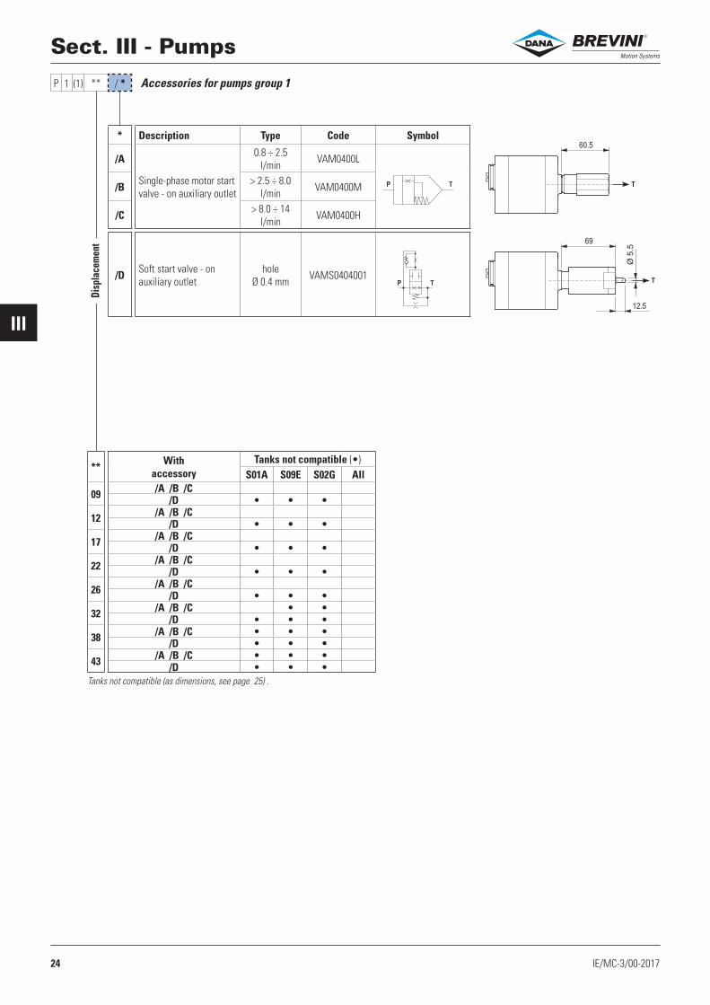
* Description Type Code Symbol
/A
Single-phase motor start valve - on auxiliary outlet
0.8 ÷ 2.5l/min VAM0400L
/B > 2.5 ÷ 8.0l/min VAM0400M
/C > 8.0 ÷ 14l/min VAM0400H
/D Soft start valve - on auxiliary outlet
hole Ø 0.4 mm VAMS0404001
Accessories for pumps group 1
** With accessory
Tanks not compatible (•)S01A S09E S02G All
09 /A /B /C /D • • •
12 /A /B /C /D • • •
17 /A /B /C /D • • •
22 /A /B /C /D • • •
26 /A /B /C /D • • •
32 /A /B /C • •/D • • •
38 /A /B /C • • •/D • • •
43 /A /B /C • • •/D • • •
Tanks not compatible (as dimensions, see page 25) .
Disp
lace
men
t
®

25IE/MC-4-5/01-2017
IVV
MC ........ * ** * (*) ** /* -
Tank (S = with tank and tubes kit; G = only tubes kit, without tank; OMIT if without tank and without tubes kit) Capacity litersFeatures (material and construction)Mounting position: (H = horizontal; V = vertical)Variants (00 = standard, no variant) - OMIT if with tubes kitOrientation - OMIT if with tubes kit in vertical mounting positionEnd section IV and V
** Liters * Dimensions (mm) Material(*) **
Page*
PageMounting Variants Orientation
01 1 A Ø 123 - L 141 Sheet steel(H) 00
26
/1(std)/2/3/4
39
(V) 00
021,5 G 130x140 - L 135 Polyethylene
(H) 0035
(V) 00
2 A Ø 123 - L 200 Sheet steel(H) 00
26(V) 00
032,5 G 130x140 - L 235 Polyethylene
(H) 0035
(V) 00
3 A Ø 123 - L 330 Sheet steel(H) 00
26(V) 00
044 G 130x140 - L 295 Polyethylene
(H) 0035
(V) 00
4 L 180 - L 210 Polyethylene(H) 00
36(V) 00
05
5 B Ø 175 - L 246 Sheet steel(H) 00-01-02-03-04
27(V) 00
5 C Ø 200 - L 210 Sheet steel(H) 00
28(V) 00
5 F 180 - L 240 Polypropylene(H) 00
34(V) 00
06 6 B Ø 175 - L 308 Sheet steel(H) 00-04
27(V) 00
07
7 E 154x188 - L 299 Sheet steel (V) 00-01 30
7 F 180 - L 308 Polypropylene(H) 00
34(V) 00
7 L 180 - L 310 Polyethylene(H) 00
37(V) 00
7 M 180 - L 335 Polietilene(H) 00
38(V) 00
088 B Ø 175 - L 370 Sheet steel
(H) 00-0427
(V) 00
8 C Ø 200 - L 306 Sheet steel(H) 00
28(V) 00
09 9E 230x130 - L 350 Sheet steel
(H) 0031
(V) 00L 180 - L 370 Polietilene (V) 00 37
10
10 C Ø 200 - L 373 Sheet steel(H) 00
28(V) 00
10 D Ø 217 - L 273 Sheet steel(H) 00
29(V) 00
10 L 180 - L 410 Polyethylene(H) 00
37(V) 00
12 12 D Ø 217 - L 370 Sheet steel(H) 00
29(V) 00
14 14 E 255x193 - L 366 Sheet steel (V) 00-01 32
25 25 E 250x255 - L 436 Sheet steel(H) 00-01
33(V) 00-01
Sect. IV - Tanks / Sect. V - Tubes kit®

26 IE/MC-4-5/01-2017
IVV
37
L
Ø 1
23
(49149800)
* ** * (H) ** * -
* ** * (V) ** * -
L
Ø 123
101
(60502700)
(49149800)
Tanks Ø 123 - Sheet steel, capacity 1-2-3 liters - Horizontal mounting
Sect. IV - Tanks / Sect. V - Tubes kit
Tanks Ø 123 - Sheet steel, capacity 1-2-3 liters - Vertical mounting
(1 ) Variant - OMIT if without tank but with tubes kit
(1 ) Variant - OMIT if without tank but with tubes kit
Other variants
Other variants
(..) spare parts
(..) spare parts
(black painted)
(black painted)
Variant Tank Variant Tank Variant Tank Variant Tank
Variant Tank Variant Tank Variant Tank Variant Tank
Capa
city
Feat
ures
Mou
ntin
g
Vari
ant (
1) L (mm)
Capacity (liters)
Tank (with plug)
Tank fixing kit
(screws and O-Ring)
Nom
inal
Full
Usa
ble
01
A (H) 00
141 1 1.0 0.7 90310000
1701008602 200 2 1.6 1.5 90310001
03 330 3 3 2.8 90310002
Capa
city
Feat
ures
Mou
ntin
g
Vari
ant (
1) L (mm)
Capacity (liters)
Tank (with plug)
Tank fixing kit
(screws and O-Ring)
Nom
inal
Full
Usa
ble
01
A (V) 00
141 1 0.9 0.7 90310009
1701008602 200 2 1.6 1.5 90310010
03 330 3 2.9 2.9 90310011
®

27IE/MC-4-5/01-2017
IVV
* ** * (H) ** * -
* ** * (V) ** * -
L
Ø 1
75
25
51 (49149800)
(R78100021)
L
Ø 175
127
(60502700)
(49149800)
(R78100021)
(49149800)
(R78100021)
(60306400)
(R78100021)
(49107500)
(R78100021)
(49121900)
(R78100021)
Tanks Ø 175 - Sheet steel, capacity 5-6-8 liters - Horizontal mounting
Tanks Ø 175 - Sheet steel, capacity 5-6-8 liters - Vertical mounting
Sect. IV - Tanks / Sect. V - Tubes kit
(1 ) Variant - OMIT if without tank but with tubes kit
(1 ) Variant - OMIT if without tank but with tubes kit
Other variants
Other variants
(..) spare parts
(..) spare parts
(black painted)
(black painted)
Variant Tank05
B (H) 0190310003
0608
Variant Tank05
B (H) 0290310149
0608
Variant Tank05
B (H) 0390310134
06 9031006208 90310069
Variant Tank05
B (H) 0490310176
0608
Variant Tank Variant Tank Variant Tank Variant Tank
Capa
city
Feat
ures
Mou
ntin
g
Vari
ant (
1) L (mm)
Capacity (liters)
Tank (with plugs)
Tank fixing kit
(screws and O-Ring)
Nom
inal
Full
Usa
ble
05
B (H) 00
246 5 4.7 4.5 90310003
1701008606 308 6 6 5.9 90310004
08 370 8 8 7.3 90310005
Capa
city
Feat
ures
Mou
ntin
g
Vari
ant (
1) L (mm)
Capacity (liters)
Tank (with plugs)
Tank fixing kit
(screws and O-Ring)
Nom
inal
Full
Usa
ble
05
B (V) 00
246 5 4.3 4.1 90310012
1701008606 308 6 5.8 5.5 90310013
08 370 8 7.5 7.2 90310015
®
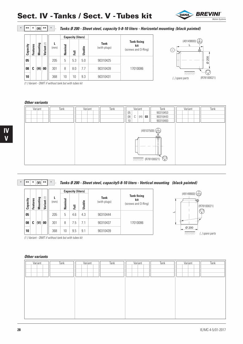
28 IE/MC-4-5/01-2017
IVV
* ** * (H) ** * -
* ** * (V) ** * -
(49149800)
(R78100021)
Ø 2
00
L
(49149800)
(R78100021)
Ø 200
L
(49107500)
(R78100021)
Sect. IV - Tanks / Sect. V - Tubes kit
Other variants
Other variants
Tanks Ø 200 - Sheet steel, capacity 5-8-10 liters - Horizontal mounting
Tanks Ø 200 - Sheet steel, capacity5-8-10 liters - Vertical mounting
(1 ) Variant - OMIT if without tank but with tubes kit
(1 ) Variant - OMIT if without tank but with tubes kit
Variant Tank Variant Tank Variant Tank05
C (H) 0390310453
08 9031044310 90310483
Variant Tank
Variant Tank Variant Tank Variant Tank Variant Tank
(..) spare parts
(..) spare parts
(black painted)
(black painted)
Capa
city
Feat
ures
Mou
ntin
g
Vari
ant (
1) L (mm)
Capacity (liters)
Tank (with plugs)
Tank fixing kit
(screws and O-Ring)
Nom
inal
Full
Usa
ble
05
C (H) 00
205 5 5.3 5.0 90310425
1701008608 301 8 8.0 7.7 90310428
10 368 10 10 9.3 90310431
Capa
city
Feat
ures
Mou
ntin
g
Vari
ant (
1) L (mm)
Capacity (liters)
Tank (with plugs)
Tank fixing kit
(screws and O-Ring)
Nom
inal
Full
Usa
ble
05
C (V) 00
205 5 4.6 4.3 90310444
1701008608 301 8 7.5 7.1 90310437
10 368 10 9.5 9.1 90310439
®
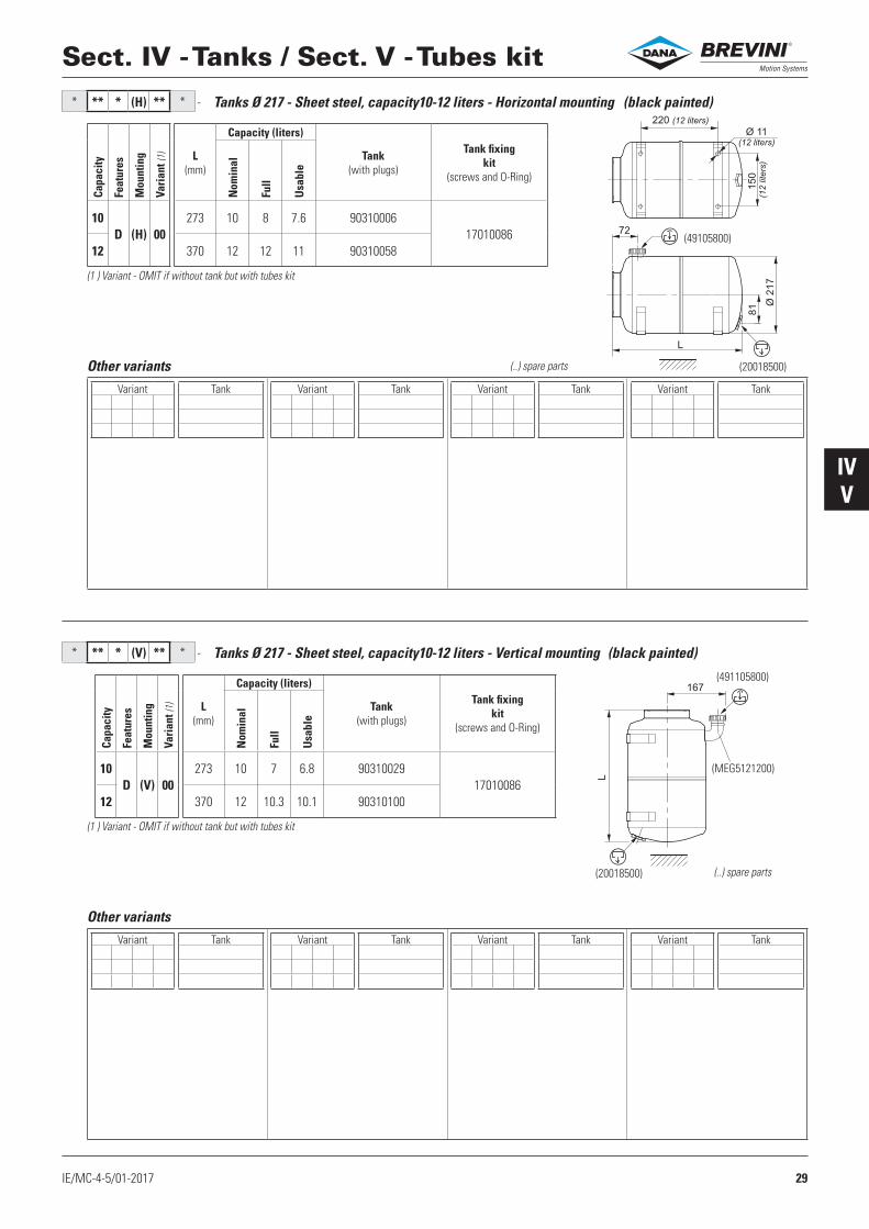
29IE/MC-4-5/01-2017
IVV
* ** * (H) ** * -
* ** * (V) ** * -
(49105800)
220 (12 liters)
72
L
Ø 11
(12 liters)
Ø 2
17
81
150
(12 liters
)
(20018500)
(491105800)
(MEG5121200)
167
L
(20018500)
Sect. IV - Tanks / Sect. V - Tubes kit
Other variants
Other variants
Tanks Ø 217 - Sheet steel, capacity10-12 liters - Horizontal mounting
Tanks Ø 217 - Sheet steel, capacity10-12 liters - Vertical mounting
(1 ) Variant - OMIT if without tank but with tubes kit
(1 ) Variant - OMIT if without tank but with tubes kit
Variant Tank Variant Tank Variant Tank Variant Tank
Variant Tank Variant Tank Variant Tank Variant Tank
(..) spare parts
(..) spare parts
(black painted)
(black painted)
Capa
city
Feat
ures
Mou
ntin
g
Vari
ant (
1) L (mm)
Capacity (liters)
Tank (with plugs)
Tank fixing kit
(screws and O-Ring)
Nom
inal
Full
Usa
ble
10D (H) 00
273 10 8 7.6 9031000617010086
12 370 12 12 11 90310058
Capa
city
Feat
ures
Mou
ntin
g
Vari
ant (
1) L (mm)
Capacity (liters)
Tank (with plugs)
Tank fixing kit
(screws and O-Ring)
Nom
inal
Full
Usa
ble
10D (V) 00
273 10 7 6.8 9031002917010086
12 370 12 10.3 10.1 90310100
®
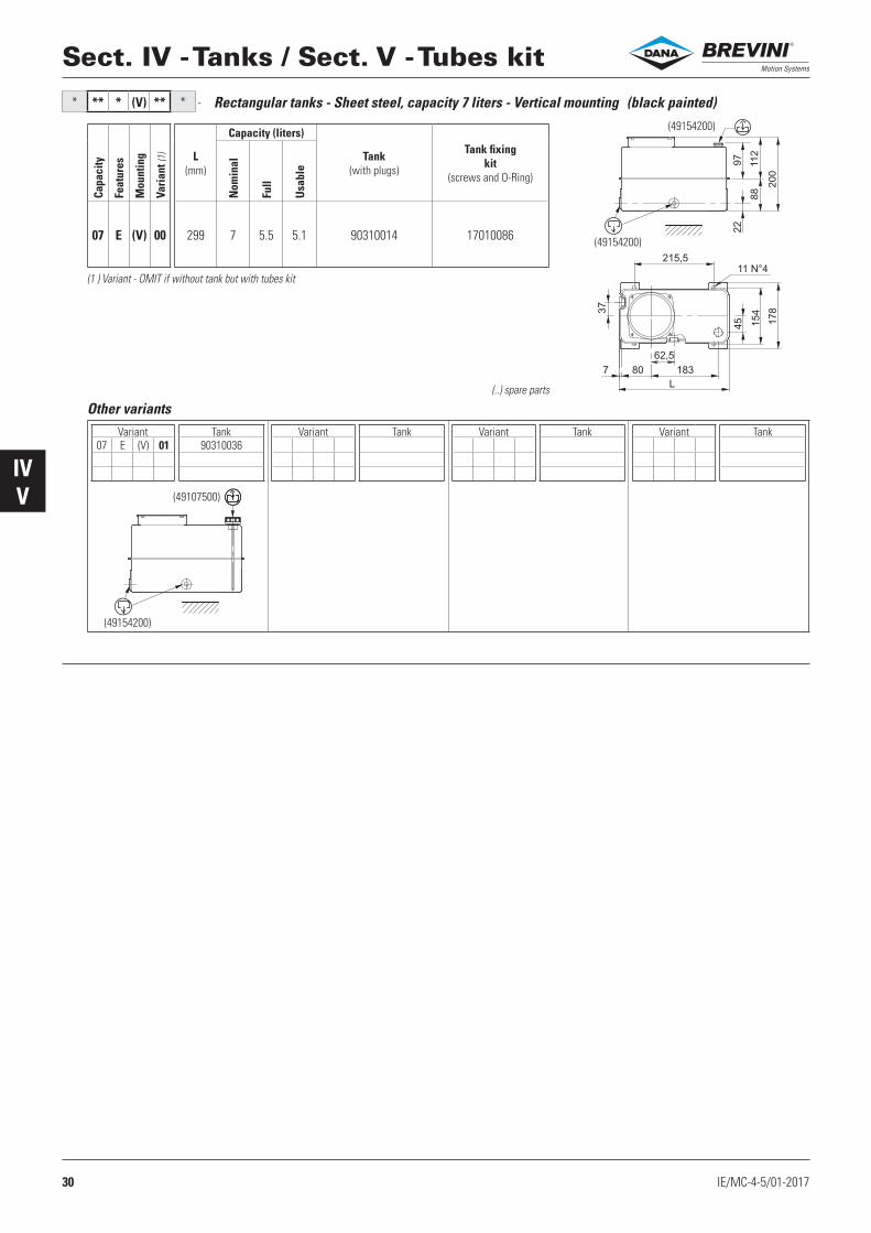
30 IE/MC-4-5/01-2017
IVV
* ** * (V) ** * -
(49154200)
(49154200)
22
45
215,5
62,5
7 80 183
L
11 N°4
37
154
178
88
200
97
112
(49107500)
(49154200)
Sect. IV - Tanks / Sect. V - Tubes kit
Variant Tank07 E (V) 01 90310036
Variant Tank Variant Tank Variant Tank
Other variants
Rectangular tanks - Sheet steel, capacity 7 liters - Vertical mounting
(1 ) Variant - OMIT if without tank but with tubes kit
(..) spare parts
(black painted)Ca
paci
ty
Feat
ures
Mou
ntin
g
Vari
ant (
1) L (mm)
Capacity (liters)
Tank (with plugs)
Tank fixing kit
(screws and O-Ring)
Nom
inal
Full
Usa
ble
07 E (V) 00 299 7 5.5 5.1 90310014 17010086
®
31IE/MC-4-5/01-2017
IVV
* ** * (H) ** * -
* ** * (V) ** * -
(49149800)
L
21125
22
22
12
130
133
93
230
(R78100021)
(49149800)
L
236
211 25
22
22
12
130
133
93
230
(R78100021)
Sect. IV - Tanks / Sect. V - Tubes kit
Variant Tank Variant Tank Variant Tank Variant Tank
Other variants
Variant Tank Variant Tank Variant Tank Variant Tank
Other variants
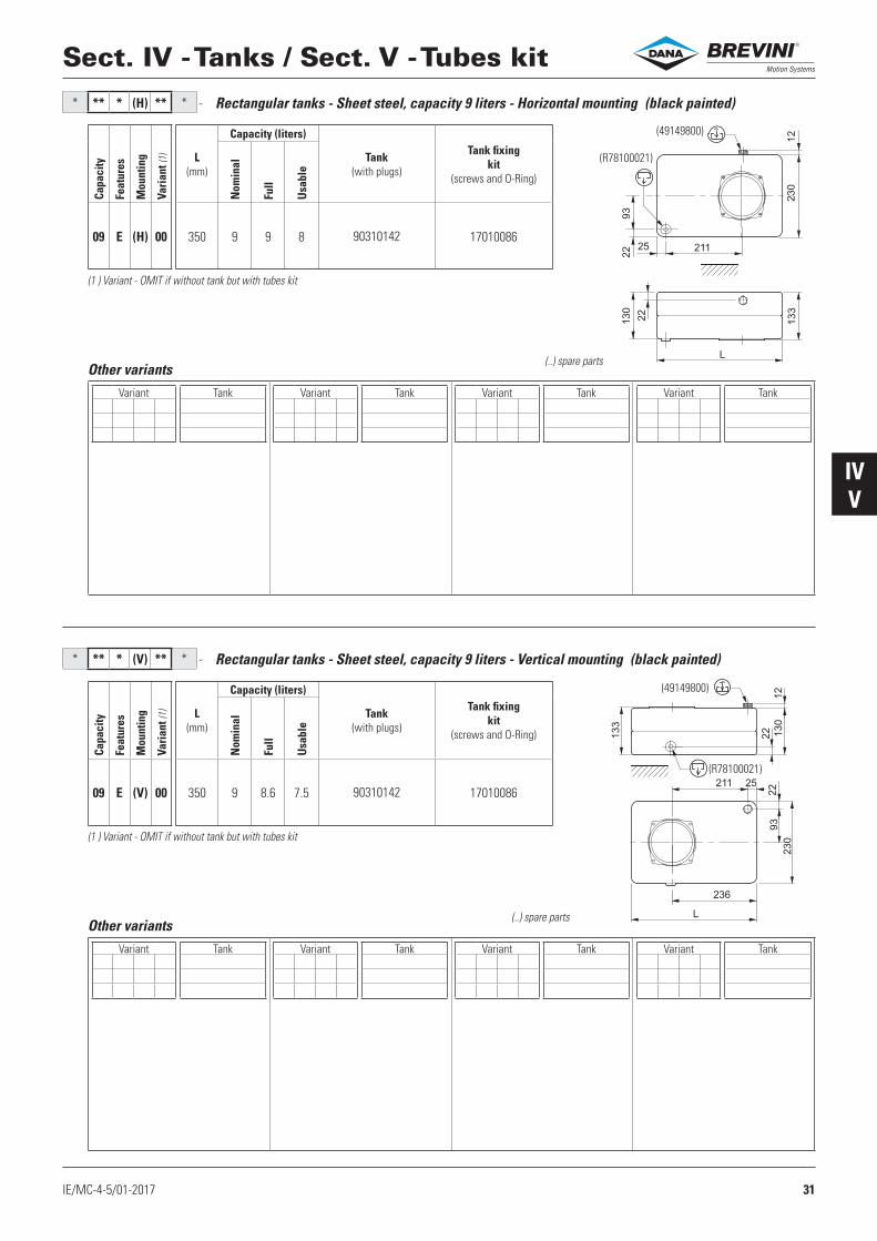
Rectangular tanks - Sheet steel, capacity 9 liters - Horizontal mounting
Rectangular tanks - Sheet steel, capacity 9 liters - Vertical mounting
(1 ) Variant - OMIT if without tank but with tubes kit
(1 ) Variant - OMIT if without tank but with tubes kit
(..) spare parts
(..) spare parts
(black painted)
(black painted)
Capa
city
Feat
ures
Mou
ntin
g
Vari
ant (
1) L (mm)
Capacity (liters)
Tank (with plugs)
Tank fixing kit
(screws and O-Ring)
Nom
inal
Full
Usa
ble
09 E (H) 00 350 9 9 8 90310142 17010086
Capa
city
Feat
ures
Mou
ntin
g
Vari
ant (
1) L (mm)
Capacity (liters)
Tank (with plugs)
Tank fixing kit
(screws and O-Ring)
Nom
inal
Full
Usa
ble
09 E (V) 00 350 9 8.6 7.5 90310142 17010086
®
32 IE/MC-4-5/01-2017
IVV
* ** * (*) ** * -
(49149800)
(49154200)
219
300
L
265
220
37
20
75 73
277.5
94
91
11
193
12
22
(49154200)
(49107500)
Sect. IV - Tanks / Sect. V - Tubes kit
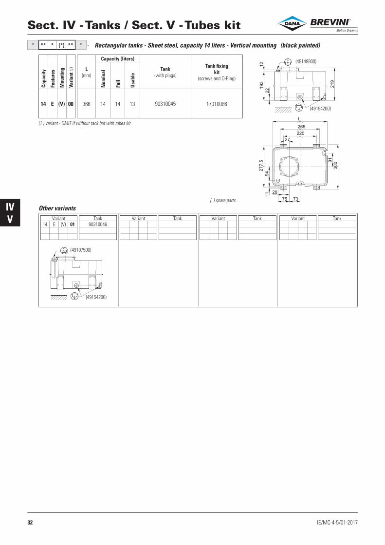
Variant Tank14 E (V) 01 90310046
Variant Tank Variant Tank Variant Tank
Other variants
Rectangular tanks - Sheet steel, capacity 14 liters - Vertical mounting
(1 ) Variant - OMIT if without tank but with tubes kit
(..) spare parts
(black painted)Ca
paci
ty
Feat
ures
Mou
ntin
g
Vari
ant (
1) L (mm)
Capacity (liters)
Tank (with plugs)
Tank fixing kit
(screws and O-Ring)
Nom
inal
Full
Usa
ble
14 E (V) 00 366 14 14 13 90310045 17010086
®
33IE/MC-4-5/01-2017
IVV
* ** * (*) ** * -
* ** * (*) ** * -
(20022600)
(49118000)19
16.5 n°4
L
474
506
105
46
(16)
(16)
(25)
(25)60
200
250
35
183.5
255
46
(20022600)
(49118000)
16.5 n°4
L
474
506
(16)
(16)
(25)
(25)
200
250
100
125
281
255
33.5
35
26
60
46
46
(20022600)
(49120600)
(20022600)
(49120600)
Sect. IV - Tanks / Sect. V - Tubes kit
Variant Tank25 E (H) 01 90310083
Variant Tank Variant Tank Variant Tank
Other variants
Variant Tank25 E (V) 01 90310124
Variant Tank Variant Tank Variant Tank
Other variants
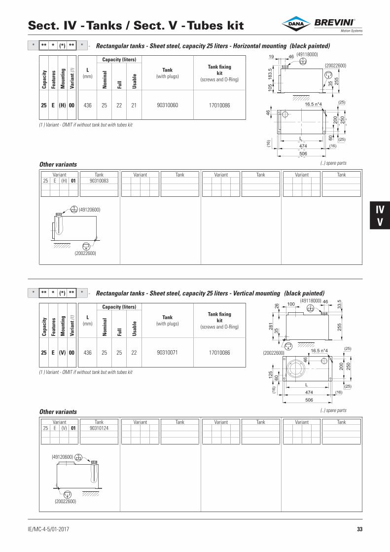
Rectangular tanks - Sheet steel, capacity 25 liters - Horizontal mounting
Rectangular tanks - Sheet steel, capacity 25 liters - Vertical mounting
(1 ) Variant - OMIT if without tank but with tubes kit
(1 ) Variant - OMIT if without tank but with tubes kit
(..) spare parts
(..) spare parts
(black painted)
(black painted)
Capa
city
Feat
ures
Mou
ntin
g
Vari
ant (
1) L (mm)
Capacity (liters)
Tank (with plugs)
Tank fixing kit
(screws and O-Ring)
Nom
inal
Full
Usa
ble
25 E (H) 00 436 25 22 21 90310060 17010086
Capa
city
Feat
ures
Mou
ntin
g
Vari
ant (
1) L (mm)
Capacity (liters)
Tank (with plugs)
Tank fixing kit
(screws and O-Ring)
Nom
inal
Full
Usa
ble
25 E (V) 00 436 25 25 22 90310071 17010086
®

34 IE/MC-4-5/01-2017
IVV
* ** * (H) ** * -
* ** * (V) ** * -
(49138700)
90
105
L
180
19
0
(49138700)
L
90 105
Sect. IV - Tanks / Sect. V - Tubes kit
Square polypropylene tanks capacity 5-7 liters - Horizontal mounting
Square polypropylene tanks capacity 5-7 liters - Vertical mounting
(..) spare parts
(..) spare parts
Operating temperature -10°C ÷ +60°C - (1 ) Variant - OMIT if without tank but with tubes kit
Operating temperature -10°C ÷ +60°C - (1 ) Variant - OMIT if without tank but with tubes kit
Capa
city
Feat
ures
Mou
ntin
g
Vari
ant (
1) L (mm)
Capacity (liters)
Tank (with plug, brackets, nuts)
Tank fixing kit
(screws and O-Ring)
Nom
inal
Full
Usa
ble
05
F (H) 00
242 5 5.4 4.5 90310313
17010086
07 308 7 7.4 6.5 90310289
Capa
city
Feat
ures
Mou
ntin
g
Vari
ant (
1) L (mm)
Capacity (liters)
Tank (with plug, brackets, nuts)
Tank fixing kit
(screws and O-Ring)
Nom
inal
Full
Usa
ble
05
F (V) 00
242 5 5.4 4.5 90310313
17010086
07 306 7 7.4 6.5 90310289
®

35IE/MC-4-5/01-2017
IVV
* ** * (H) ** * -
* ** * (V) ** * -
(C86100001)
L 130
35
104.5
MAX
MIN
MIN
MA
X
94
140
70
(V60513005)
02 = 4915350003-04 = 49138700
(49154200)
L
MA
X
MIN
MIN
MAX
Sect. IV - Tanks / Sect. V - Tubes kit
Square polyethylene tanks capacity 1.5-2.5-4 liters - Horizontal mounting
Square polyethylene tanks capacity 1.5-2.5-4 liters - Vertical mounting
Variant Tank Variant Tank Variant Tank Variant Tank
Other variants
Variant Tank Variant Tank Variant Tank Variant Tank
Other variants
Operating temperature -10°C ÷ +70°C - (1 ) Variant - OMIT if without tank but with tubes kit (..) spare parts
(..) spare parts
Operating temperature -10°C ÷ +70°C - (1 ) Variant - OMIT if without tank but with tubes kit
Capa
city
Feat
ures
Mou
ntin
g
Vari
ant (
1) L (mm)
Capacity (liters)
Tank (with plugs, clamp, nuts)
Tank fixing kit collar Ø123
(screws and O-Ring)
Nom
inal
Full
Usa
ble
02
G (H) 00
135 1.5 1.3 1 90310491
1701008703 235 2.5 2.5 2 90310484
04 295 4 3.4 2.5 90310422
Capa
city
Feat
ures
Mou
ntin
g
Vari
ant (
1) L (mm)
Capacity (liters)
Tank (with plugs, clamp, nuts)
Tank fixing kit collar Ø123
(screws and O-Ring)
Nom
inal
Full
Usa
ble
02
G (V) 00
135 1.5 1.1 0.7 90310486
1701008703 235 2.5 2.7 2.3 90310419
04 296 4 3.5 3.1 90310402
®
36 IE/MC-4-5/01-2017
IVV
* ** * (H) ** * -
* ** * (V) ** * -
(C86100001)
(49154200)
104.5
90.5
85
180
119
95
L 180
MAX
MAX
MIN
MIN
MA
X
MIN
35
(V60513005)
( )49153500
(49154200)
MA
X
MA
X
MIN
MIN
MAX
MIN
L
(49138700)
MA
X
MA
X
MIN
MIN
MAX
MIN
Sect. IV - Tanks / Sect. V - Tubes kit
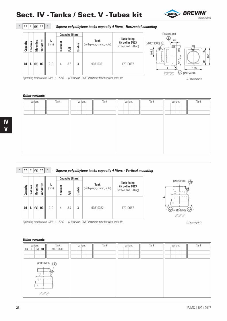
Square polyethylene tanks capacity 4 liters - Horizontal mounting
Square polyethylene tanks capacity 4 liters - Vertical mounting
Variant Tank Variant Tank Variant Tank Variant Tank
Other variants
Variant Tank04 L (V) 01 90310433
Variant Tank Variant Tank Variant Tank
Other variants
(..) spare parts
(..) spare parts
Operating temperature -10°C ÷ +70°C - (1 ) Variant - OMIT if without tank but with tubes kit
Operating temperature -10°C ÷ +70°C - (1 ) Variant - OMIT if without tank but with tubes kit
Capa
city
Feat
ures
Mou
ntin
g
Vari
ant (
1) L (mm)
Capacity (liters)
Tank (with plugs, clamp, nuts)
Tank fixing kit collar Ø123
(screws and O-Ring)
Nom
inal
Full
Usa
ble
04 L (H) 00 210 4 3.6 3 90310331 17010087
Capa
city
Feat
ures
Mou
ntin
g
Vari
ant (
1) L (mm)
Capacity (liters)
Tank (with plugs, clamp, nuts)
Tank fixing kit collar Ø123
(screws and O-Ring)
Nom
inal
Full
Usa
ble
04 L (V) 00 210 4 3.7 3 90310332 17010087
®

37IE/MC-4-5/01-2017
IVV
* ** * (*) ** * -
* ** * (*) ** * -
(C86100001)
(V60513005)
85 1
80
95
180
MAX
MAX
MIN
MIN
MA
X
MIN
20L
102.5
119
67
35(V60513005)
07= 4913870010= 49153500
(V60513005) (49154200)
MA
X
MIN
MIN
MA
X
MIN
MAX
L
(V60513005)
180
L21
(49153500)
180
9585
102* ** * (*) ** * -
Sect. IV - Tanks / Sect. V - Tubes kit
Square polyethylene tanks capacity 7-10 liters - Horizontal mounting
Square polyethylene tanks capacity 7-10 liters - Vertical mounting
(..) spare parts
(..) spare parts
Operating temperature -10°C ÷ +70°C - (1 ) Variant - OMIT if without tank but with tubes kit
Operating temperature -10°C ÷ +70°C - (1 ) Variant - OMIT if without tank but with tubes kit
Capa
city
Feat
ures
Mou
ntin
g
Vari
ant (
1) L (mm)
Capacity (liters)
Tank (with plugs, clamp, nuts)
Tank fixing kit collar Ø123
(screws and O-Ring)
Nom
inal
Full
Usa
ble
07
L (H) 00
310 7 6.7 5.5 90310330
17010087
10 410 10 8.7 7.5 90310339
Capa
city
Feat
ures
Mou
ntin
g
Vari
ant (
1) L (mm)
Capacity (liters)
Tank (with plugs, clamp, nuts)
Tank fixing kit collar Ø123
(screws and O-Ring)
Nom
inal
Full
Usa
ble
07
L (V) 00
310 7 6.7 6 90310403
17010087
10 410 10 9.8 9 90310338
Square polyethylene tanks capacity 9 liters - Vertical mounting
(..) spare parts
Operating temperature -10°C ÷ +70°C - (1 ) Variant - OMIT if without tank but with tubes kit
Capa
city
Feat
ures
Mou
ntin
g
Vari
ant (
1) L (mm)
Capacity (liters)
Tank (with plugs, clamp, nuts)
Tank fixing kit collar Ø123
(screws and O-Ring)
Nom
inal
Full
Usa
ble
09 L (V) 00 370 9 8.6 8 90310371 17010087
®
38 IE/MC-4-5/01-2017
IVV
* ** * (H) ** * -
* ** * (V) ** * -
(49155600)
L
MA
X
MIN
MIN
MAX
(49155600)
180L
122
67
113
180
MAX
MIN
MIN
MA
X
Sect. IV - Tanks / Sect. V - Tubes kit
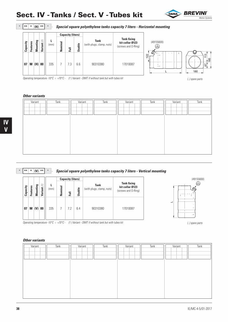
Special square polyethylene tanks capacity 7 liters - Horizontal mounting
Special square polyethylene tanks capacity 7 liters - Vertical mounting
Variant Tank Variant Tank Variant Tank Variant Tank
Other variants
Variant Tank Variant Tank Variant Tank Variant Tank
Other variants
(..) spare parts
(..) spare parts
Operating temperature -10°C ÷ +70°C - (1 ) Variant - OMIT if without tank but with tubes kit
Operating temperature -10°C ÷ +70°C - (1 ) Variant - OMIT if without tank but with tubes kit
Capa
city
Feat
ures
Mou
ntin
g
Vari
ant (
1) L (mm)
Capacity (liters)
Tank (with plugs, clamp, nuts)
Tank fixing kit collar Ø123
(screws and O-Ring)
Nom
inal
Full
Usa
ble
07 M (H) 00 335 7 7.3 6.6 90310380 17010087
Capa
city
Feat
ures
Mou
ntin
g
Vari
ant (
1) L (mm)
Capacity (liters)
Tank (with plugs, clamp, nuts)
Tank fixing kit collar Ø123
(screws and O-Ring)
Nom
inal
Full
Usa
ble
07 M (V) 00 335 7 7.2 6.4 90310380 17010087
®
39IE/MC-4-5/01-2017
IVV
* ** * (*) ** /* -
P
P
P
P
P
P
P
P
P
P
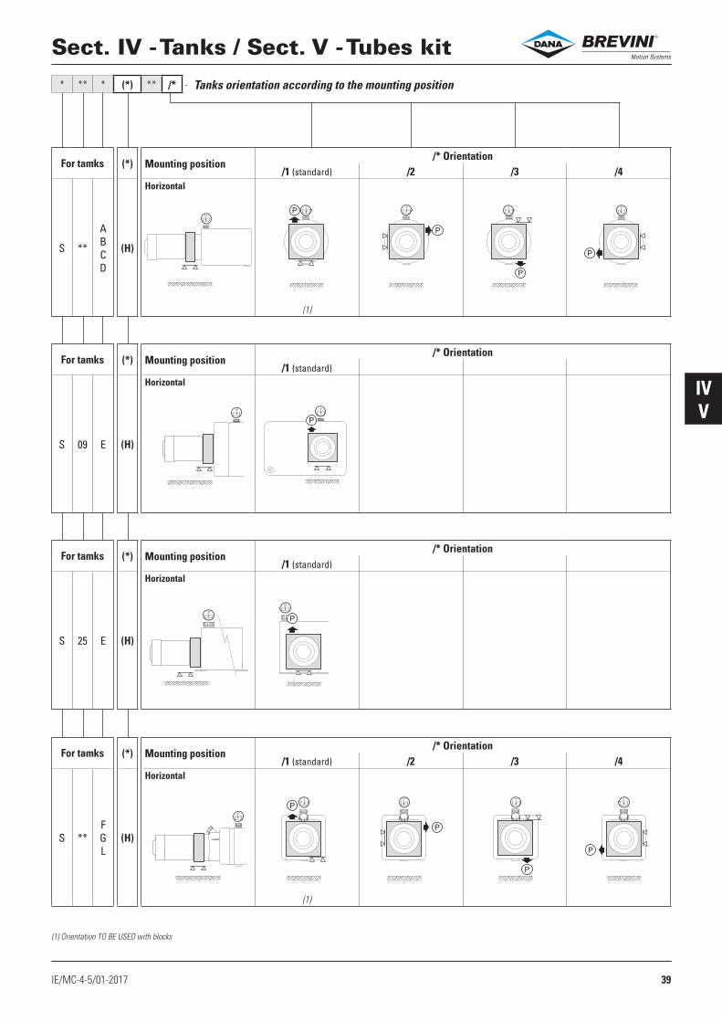
Sect. IV - Tanks / Sect. V - Tubes kit
For tamks (*) Mounting position/* Orientation
/1 (standard) /2 /3 /4
S **
ABC D
(H)
Horizontal
(1)
Tanks orientation according to the mounting position
For tamks (*) Mounting position/* Orientation
/1 (standard)
S 09 E (H)
Horizontal
For tamks (*) Mounting position/* Orientation
/1 (standard)
S 25 E (H)
Horizontal
For tamks (*) Mounting position/* Orientation
/1 (standard) /2 /3 /4
S **FGL
(H)
Horizontal
(1)
(1) Orientation TO BE USED with blocks
®
40 IE/MC-4-5/01-2017
IVV
* ** * (*) ** /* -
P P P P
P P P P
P P P P
P P P P
Sect. IV - Tanks / Sect. V - Tubes kit
For tamks (*) Mounting position/* Orientation
/1 (standard) /2 /3 /4
S **
ABCDFGL
(V)
Vertical
(2)
Tanks orientation according to the mounting position
For tamks (*) Mounting position/* Orientation
/1 (standard) /2 /3 /4
S 07 E (V)
Vertical
(1)
For tamks (*) Mounting position/* Orientation
/1 (standard) /2 /3 /4
S 0925 E (V)
Vertical
(1)
For tamks (*) Mounting position/* Orientation
/1 (standard) /2 /3 /4
S 14 E (V)
Vertical
(1)
(1) Orientation TO BE USED with blocks
(2) D Orientation DO NOT USE with blocks
®

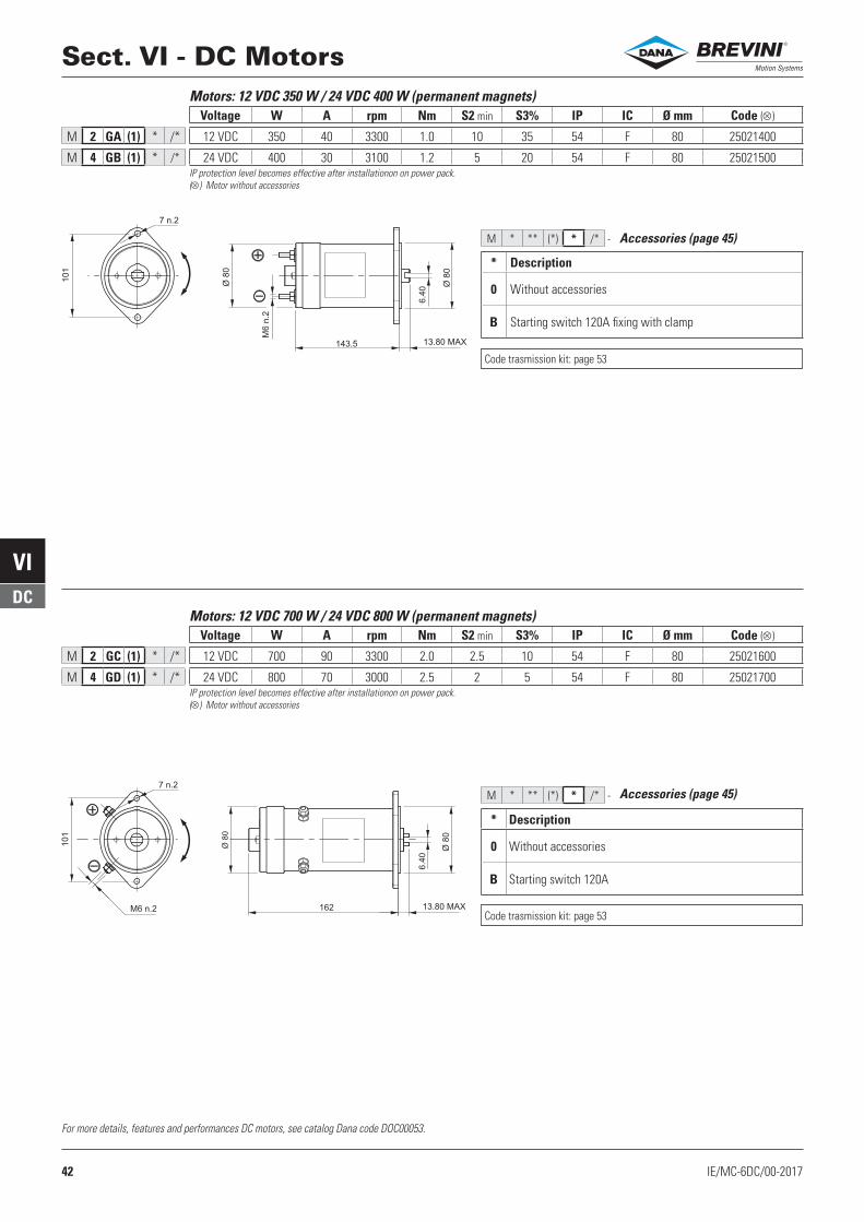
41IE/MC-6DC/00-2017
VIDC
MC ........ M * ** (*) * /* -
Sect. VI - DC MotorsMotorVoltagePower / SizeVersionAccessoriesOrientationEnd section VI
* Voltage ** Power Size (*) Version Page * Accessories /* Orientation Page
2 12 VDC
GA 350 W Ø 80 (1) Std 42 0 - B
/1/2/3 /4
Std 46
GC 700 W Ø 80 (1) Std 42 0 - BAA 1500 W Ø 115 (1) Std 43 0 - B - C - D - F - G - H EN 1600 W Ø 115 (1) Std 43 0 - B - C - EGN 1600 W Ø 115 (1) Std 44 0 - B - C - E
4 24 VDC
GB 400 W Ø 80 (1) Std 42 0 - BGD 800 W Ø 80 (1) Std 42 0 - BAB 2000 W Ø 115 (1) Std 43 0 - B - C - D - F - G - H ES 2200 W Ø 115 (1) Std 43 0 - B - C - EGP 2200 W Ø 115 (1) Std 44 0 - B - C - EGJ 3000 W Ø 125 (1) Std 44 0 - B - C - EFB 3000 W Ø 125 (1) Std 44 0 - B - C - E
* Accessories description Page0 Without accessories —B Starting switch 45C Thermal protection —D (•) Ventilation 45E Starting switch + thermal protection —F (•) Starting switch + ventilation —G Thermal protection + ventilation —H (•) Starting switch + thermal protection + ventilation —
(•)= IP protection level becomes effective after installationon on power pack.
Acquires IP 10 level with “ventilation” accessory.
For more details, features and performances DC motors, see catalog Dana code DOC00053.
All motors are equipped with a transmission kit (coupling and components for the assembly)
®
42 IE/MC-6DC/00-2017
VIDC
143.5
M6 n
. 2
7 n.2
Ø 8
0
Ø 8
0
101
6.4
0
13.80 MAX
162M6 n.2
7 n.2
Ø 8
0
Ø 8
0
101
6.4
0
13.80 MAX
M * ** (*) * /* -
M * ** (*) * /* -
W A rpm Nm S2 min S3% IP IC Ø mm
M 2 GA (1) * /* 12 VDC 350 40 3300 1.0 10 35 54 F 80 25021400
M 4 GB (1) * /* 24 VDC 400 30 3100 1.2 5 20 54 F 80 25021500
W A rpm Nm S2 min S3% IP IC Ø mm
M 2 GC (1) * /* 12 VDC 700 90 3300 2.0 2.5 10 54 F 80 25021600
M 4 GD (1) * /* 24 VDC 800 70 3000 2.5 2 5 54 F 80 25021700
* Description
0 Without accessories
B Starting switch 120A fixing with clamp
Accessories (page 45)
IP protection level becomes effective after installationon on power pack.
( ) Motor without accessories
Sect. VI - DC MotorsMotors: 12 VDC 350 W / 24 VDC 400 W (permanent magnets)
Accessories (page 45)
IP protection level becomes effective after installationon on power pack.
( ) Motor without accessories
* Description
0 Without accessories
B Starting switch 120A
Motors: 12 VDC 700 W / 24 VDC 800 W (permanent magnets)
For more details, features and performances DC motors, see catalog Dana code DOC00053.
Code ( )Voltage
Code ( )Voltage
Code trasmission kit: page 53
Code trasmission kit: page 53
®
43IE/MC-6DC/00-2017
VIDC
M * ** (*) * /* -
17312.3 MAX
Ø112
Ø9
8.3
Ø3
5
Ø1
5
6.4
M89.1 MAX11 M
AX
91
1/4-20 UNC-2A
M * ** (*) * /* -
158
Ø114
Ø35
Ø15
6.4
11 max
12.3
M5 n°2
M8
D1
E1
A2
E2
1339.1
Ø98.32
90.4
1/4-20UNC
W A rpm Nm S2 min S3% IP IC Ø mm
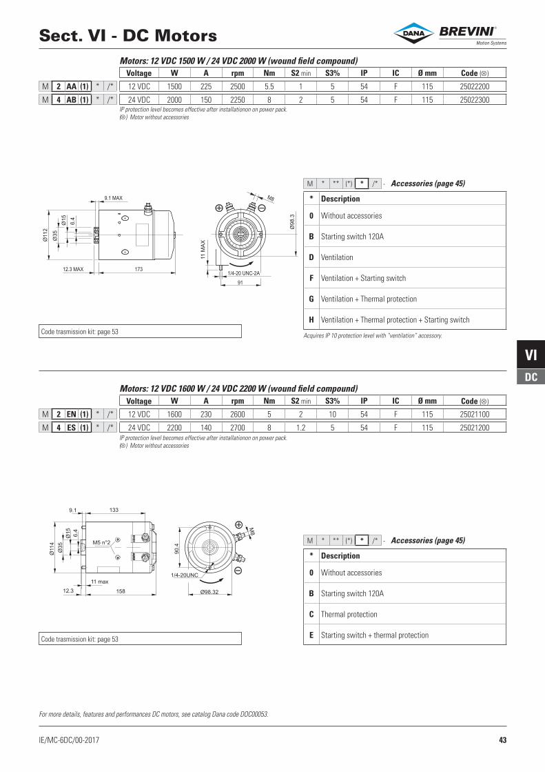
M 2 AA (1) * /* 12 VDC 1500 225 2500 5.5 1 5 54 F 115 25022200
M 4 AB (1) * /* 24 VDC 2000 150 2250 8 2 5 54 F 115 25022300
W A rpm Nm S2 min S3% IP IC Ø mm
M 2 EN (1) * /* 12 VDC 1600 230 2600 5 2 10 54 F 115 25021100
M 4 ES (1) * /* 24 VDC 2200 140 2700 8 1.2 5 54 F 115 25021200
IP protection level becomes effective after installationon on power pack.
( ) Motor without accessories
* Description
0 Without accessories
B Starting switch 120A
D Ventilation
F Ventilation + Starting switch
G Ventilation + Thermal protection
H Ventilation + Thermal protection + Starting switch
Accessories (page 45)
Acquires IP 10 protection level with “ventilation” accessory.
Motors: 12 VDC 1500 W / 24 VDC 2000 W (wound field compound)
Sect. VI - DC Motors
IP protection level becomes effective after installationon on power pack.
( ) Motor without accessories
* Description
0 Without accessories
B Starting switch 120A
C Thermal protection
E Starting switch + thermal protection
Accessories (page 45)
Motors: 12 VDC 1600 W / 24 VDC 2200 W (wound field compound)
For more details, features and performances DC motors, see catalog Dana code DOC00053.
Code ( )Voltage
Code ( )Voltage
Code trasmission kit: page 53
Code trasmission kit: page 53
®
44 IE/MC-6DC/00-2017
VIDC
M * ** (*) * /* -
M * ** (*) * /* -
Ø114.3
Ø35
Ø15
6.4
3
9.1
11.8
M5 n°2
M8
121.28.4
Ø98.32161.8
90.4
1/4-20UNC
W A rpm Nm S2 min S3% IP IC Ø mm
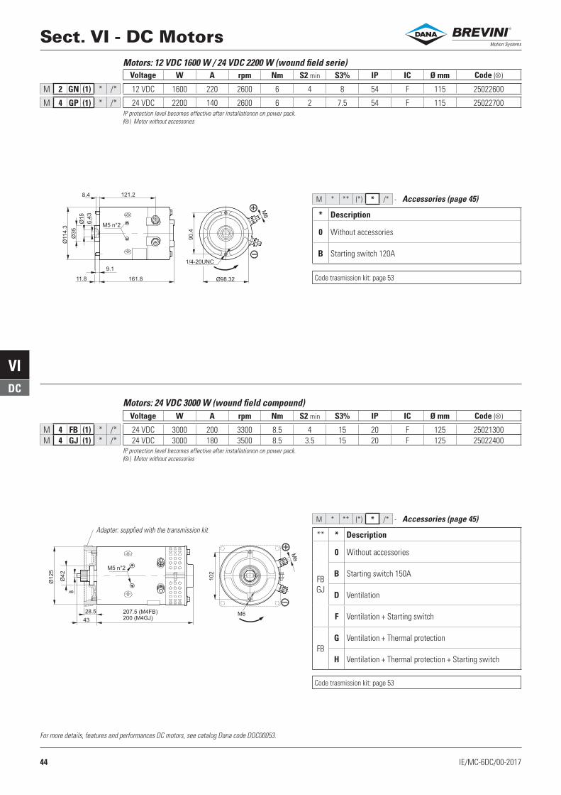
M 4 FB (1) * /* 24 VDC 3000 200 3300 8.5 4 15 20 F 125 25021300M 4 GJ (1) * /* 24 VDC 3000 180 3500 8.5 3.5 15 20 F 125 25022400
W A rpm Nm S2 min S3% IP IC Ø mm
M 2 GN (1) * /* 12 VDC 1600 220 2600 6 4 8 54 F 115 25022600
M 4 GP (1) * /* 24 VDC 2200 140 2600 6 2 7.5 54 F 115 25022700
200 (M4GJ)M6
43
28.5 207.5 (M4FB)
Ø125
Ø42
102
8
M5 n°2
M8
Sect. VI - DC Motors
For more details, features and performances DC motors, see catalog Dana code DOC00053.
IP protection level becomes effective after installationon on power pack.
( ) Motor without accessories
Accessories (page 45)
Motors: 24 VDC 3000 W (wound field compound)
IP protection level becomes effective after installationon on power pack.
( ) Motor without accessories
* Description
0 Without accessories
B Starting switch 120A
Accessories (page 45)
Motors: 12 VDC 1600 W / 24 VDC 2200 W (wound field serie)Code ( )Voltage
Code ( )Voltage
Adapter: supplied with the transmission kit** * Description
FBGJ
0 Without accessories
B Starting switch 150A
D Ventilation
F Ventilation + Starting switch
FBG Ventilation + Thermal protection
H Ventilation + Thermal protection + Starting switch
Code trasmission kit: page 53
Code trasmission kit: page 53
®

45IE/MC-6DC/00-2017
VIDC
72
Female Faston
6.3-08 N.2
57.3
20
Ø 4
0
21
M6 N
. 25
M * ** (*) B /* -
182.5
Female Faston
6.3-08 N.2
64.5
29
Ø 5
4.5
26
M8 N
.2
5
M * ** (*) C /* -
M * ** (*) * /* -
118
118
9 (N°4)
55.9 207.553.2
5
46 173118
11
8
9 (N°4)
5
52.6
Ø
Sect. VI - DC Motors
Accessory: Starting switch
120A starting switchCode (•) VDC For motors
KIT07012.027 12 M2GA - M2GC KIT07012.032 24 M4GB - M4GDKIT07012.033 12 M2AAKIT07012.034 24 M4ABKIT07012.025 12 M2EN - M2GN KIT07012.026 24 M4ES - M2GP
150A starting switchCode (•) VDC For motors
KIT07012.019 24 M4FB - M4GJ
Accessory: Thermal protection
Accessory: Ventilation (motor included)
IP 10 protectionIP 10 protection
For more details, features and performances DC motors, see catalog Dana code DOC00053.
* Code (•) VDC For motors
D KIT01008.065 12 M2AA
G KIT01008.088 12 M2AA + thermal protecion
D KIT01008.067 24 M4AB
G KIT01008.077 24 M4AB + thermal protecion
(•) Complete kit with all assembly components.
(•) Complete kit with all assembly components (motor, transmission kit, etc).
For more details, features and performances DC motors, see catalog Dana code DOC00053.
Thermal protectionCode Ø mm For motors
90340009 16 M2EN - M4ES
* Code (•) VDC For motors
D KIT01008.118 24 M4FB
D KIT01008.215 24 M4GJ
G KIT01008.119 24 M4FB + thermal protecion
®

46 IE/MC-6DC/00-2017
VIDC
M * ** (*) * /* -
/1
/2/4
/3
Std
P
Sect. VI - DC MotorsMotor orientation
Starting switch and poles position.
Do not use “orientation 1” with blocks.
®

47IE/MC-6AC/00-2017
VIAC
MC ........ M * * * * (*) /* -
Sect. VI - AC MotorsMotorPhasesPolesSizePower rangeVersionOrientationEnd section VI
Motors supplied with all assembly components (transmission kit, coupling, etc).
* Phases * Poles * Size * Power range Page (*) Version /* Orientation PagePower Voltage
M Monofase
2
L 71 A 0.37 kW 230 Vac 50 Hz 48
(1) Std
/1/2/3 /4
Std 52
L 71 B 0.55 kW 230 Vac 50 Hz 48
S 71 A 0.75 kW 230 Vac 50 Hz 50
S 71 B 1.10 kW 230 Vac 50 Hz 50
M 80 A 0.75 kW 230 Vac 50 Hz 48
M 80 B 1.10 kW 230 Vac 50 Hz 48
N 90 A 1.50 kW 230 Vac 50 Hz 48
N 90 B 2.20 kW 230 Vac 50 Hz 48
P 100 A 3.00 kW 230 Vac 50 Hz 48
4
L 71 A 0.25 kW 230 Vac 50 Hz 48
L 71 B 0.37 kW 230 Vac 50 Hz 48
S 71 C 0.85 kW 230 Vac 50 Hz 50
M 80 A 0.55 kW 230 Vac 50 Hz 48
M 80 B 0.75 kW 230 Vac 50 Hz 48
N 90 A 1.10 kW 230 Vac 50 Hz 48
N 90 B 1.50 kW 230 Vac 50 Hz 48
V 90 A 1.80 kW 230 Vac 50 Hz 51
V 90 B 3.00 kW 230 Vac 50 Hz 51
P 100 A 2.20 kW 230 Vac 50 Hz 48
T Trifase
2
R 63 A 0.18 kW 230/400 Vac 50 Hz 49
R 63 B 0.25 kW 230/400 Vac 50 Hz 49
L 71 A 0.37 kW 230/400 Vac 50 Hz 49
L 71 B 0.55 kW 230/400 Vac 50 Hz 49
S 71 A 0.75 kW 230/400 Vac 50 Hz 50
S 71 B 1.10 kW 230/400 Vac 50 Hz 50
M 80 A 0.75 kW 230/400 Vac 50 Hz 49
M 80 B 1.10 kW 230/400 Vac 50 Hz 49
T 80 A 2.70 kW 230/400 Vac 50 Hz 51
T 80 B 2.70 kW 230/400 Vac 50 Hz 51
N 90 A 1.50 kW 230/400 Vac 50 Hz 49
N 90 B 2.20 kW 230/400 Vac 50 Hz 49
P 100 A 3.00 kW 230/400 Vac 50 Hz 49
P 112 B 4.00 kW 230/400 Vac 50 Hz 49
4
R 63 A 0.12 kW 230/400 Vac 50 Hz 49
R 63 B 0.18 kW 230/400 Vac 50 Hz 49
L 71 A 0.25 kW 230/400 Vac 50 Hz 49
L 71 B 0.37 kW 230/400 Vac 50 Hz 49
S 71 A 0.75 kW 230/400 Vac 50 Hz 50
M 80 A 0.55 kW 230/400 Vac 50 Hz 49
M 80 B 0.75 kW 230/400 Vac 50 Hz 49
T 80 A 2.20 kW 230/400 Vac 50 Hz 51
T 80 B 2.20 kW 230/400 Vac 50 Hz 51
T 80 C 2.20 kW 230/400 Vac 50 Hz 51
T 80 D 3.00 kW 230/400 Vac 50 Hz 51
N 90 A 1.10 kW 230/400 Vac 50 Hz 49
N 90 B 1.50 kW 230/400 Vac 50 Hz 49
P 100 A 2.20 kW 230/400 Vac 50 Hz 49
P 100 B 3.00 kW 230/400 Vac 50 Hz 49
P 112 C 4.00 kW 230/400 Vac 50 Hz 49
®

48 IE/MC-6AC/00-2017
VIAC
D1
L2
D2
H1
L1
Single-phase motors 2-4 Poles - 230 Vac 50Hz - Version B14
Phas
esPo
les
Size
D1 (•)
D2 (•)
H1 (•)
L1 (•)
Power range
Cabl
e gl
and
met
ric th
red Adapter
SingleMotor
Transmission kit(for pump)
PowerkW Voltage IP IC S1 Code
Screw UNI 5931
L2
M M 2 L A (1) 2 2 71 14 148 115 208 0.37 230 Vac 50 Hz 54 F Si 20-25 61000700 M6x20 19.5 M12E2000 KIT01008.006 (Gr.05)KIT01008.001 (Gr.1)M M 2 L B (1) 2 2 71 14 148 115 208 0.55 230 Vac 50 Hz 54 F Si 20-25 61000700 M6x20 19.5 M12F2000
M M 2 M A (1) 2 2 80 19 170 126 234 0.75 230 Vac 50 Hz 54 F Si 20-25 61000800 M6x20 30.4 M13G2000 KIT01008.005 (Gr.05)KIT01008.002 (Gr.1)M M 2 M B (1) 2 2 80 19 170 126 234 1.10 230 Vac 50 Hz 54 F Si 20-25 61000800 M6x20 30.4 M13H2000
M M 2 N A (1) 2 2 90 24 185 142 247 1.50 230 Vac 50 Hz 54 F Si 20-25 61000900 M8x21 40.4 M14L2000 KIT01008.007 (Gr.05)KIT01008.003 (Gr.1)M M 2 N B (1) 2 2 90 24 185 142 272 2.20 230 Vac 50 Hz 54 F Si 20-25 61000900 M8x21 40.4 M14N2000
M M 2 P A (1) 2 2 100 28 210 155 310 3.00 230 Vac 50 Hz 54 F Si 25-32 61001000 M8x28 75 M15P2000 KIT01008.013 (Gr.05)KIT01008.004 (Gr.1)
M M 4 L A (1) 2 4 71 14 148 115 208 0.25 230 Vac 50 Hz 54 F Si 20-25 61000700 M6x20 19.5 M12D4000 KIT01008.006 (Gr.05)KIT01008.001 (Gr.1)M M 4 L B (1) 2 4 71 14 148 115 208 0.37 230 Vac 50 Hz 54 F Si 20-25 61000700 M6x20 19.5 M12E4000
M M 4 M A (1) 2 4 80 19 170 126 234 0.55 230 Vac 50 Hz 54 F Si 20-25 61000800 M6x20 30.4 M13F4000 KIT01008.005 (Gr.05)KIT01008.002 (Gr.1)M M 4 M B (1) 2 4 80 19 170 126 234 0.75 230 Vac 50 Hz 54 F Si 20-25 61000800 M6x20 30.4 M13G4000
M M 4 N A (1) 2 4 90 24 185 142 247 1.10 230 Vac 50 Hz 54 F Si 20-25 61000900 M8x21 40.4 M14H4000 KIT01008.007 (Gr.05)KIT01008.003 (Gr.1)M M 4 N B (1) 2 4 90 24 185 142 272 1.50 230 Vac 50 Hz 54 F Si 20-25 61000900 M8x21 40.4 M14L4000
M M 4 P A (1) 2 4 100 28 210 155 310 2.20 230 Vac 50 Hz 54 F Si 25-32 61001000 M8x28 75 M15N4000 KIT01008.013 (Gr.05)KIT01008.004 (Gr.1)
Sect. VI - AC Motors
(•)= Approximate dimensions
Adapter: supplied with the transmission kit
®

49IE/MC-6AC/00-2017
VIAC
D1
L2
D2
H1
L1
Sect. VI - AC Motors
Three-phase motors 2-4 Poles - 230/400 Vac 50Hz - Version B14
Phas
esPo
les
Size
D1 (•)
D2 (•)
H1 (•)
L1 (•)
Power range
Cabl
e gl
and
met
ric th
red Adapter
SingleMotor
Transmission kit(for pump)
PowerkW Voltage IP IC S3 Code
Screw UNI 5931
L2
M T 2 R A (1) 3 2 63 11 125 95 189 0.18 230/400 Vac 50 Hz 54 F 60% 16-20 61004300 M5x16 19.5 M31C2000 KIT01008.008 (Gr.05)KIT01008.014 (Gr.1)M T 2 R B (1) 3 2 63 11 125 95 189 0.25 230/400 Vac 50 Hz 54 F 60% 16-20 61004300 M5x16 19.5 M31D2000
M T 2 L A (1) 3 2 71 14 148 115 208 0.37 230/400 Vac 50 Hz 54 F 60% 20-25 61000700 M6x20 19.5 M32E2000 KIT01008.006 (Gr.05)KIT01008.001 (Gr.1)M T 2 L B (1) 3 2 71 14 148 115 208 0.55 230/400 Vac 50 Hz 54 F 60% 20-25 61000700 M6x20 19.5 M32F2000
M T 2 M A (1) 3 2 80 19 170 126 234 0.75 230/400 Vac 50 Hz 54 F 60% 20-25 61000800 M6x20 30.4 M33G2000 KIT01008.005 (Gr.05)KIT01008.002 (Gr.1)M T 2 M B (1) 3 2 80 19 170 126 234 1.10 230/400 Vac 50 Hz 54 F 60% 20-25 61000800 M6x20 30.4 M33H2000
M T 2 N A (1) 3 2 90 24 185 142 247 1.50 230/400 Vac 50 Hz 54 F 60% 20-25 61000900 M8x21 40.4 M34L2000 KIT01008.007 (Gr.05)KIT01008.003 (Gr.1)M T 2 N B (1) 3 2 90 24 185 142 272 2.20 230/400 Vac 50 Hz 54 F 60% 20-25 61000900 M8x21 40.4 M34N2000
M T 2 P A (1) 3 2 100 28 210 155 310 3.00 230/400 Vac 50 Hz 54 F 60% 25-32 61001000 M8x28 75 M35P2000 KIT01008.013 (Gr.05)KIT01008.004 (Gr.1)M T 2 P B (1) 3 2 112 28 225 182 325 4.00 230/400 Vac 50 Hz 54 F 60% 25-32 61001000 M8x28 75 M36Q2000
M T 4 R A (1) 3 4 63 11 125 95 189 0.12 230/400 Vac 50 Hz 54 F 60% 16-20 61004300 M5x16 19.5 M31B4000 KIT01008.008 (Gr.05)KIT01008.014 (Gr.1)M T 4 R B (1) 3 4 63 11 125 95 189 0.18 230/400 Vac 50 Hz 54 F 60% 16-20 61004300 M5x16 19.5 M31C4000
M T 4 L A (1) 3 4 71 14 148 115 208 0.25 230/400 Vac 50 Hz 54 F 60% 20-25 61000700 M6x20 19.5 M32D4000 KIT01008.006 (Gr.05)KIT01008.001 (Gr.1)M T 4 L B (1) 3 4 71 14 148 115 208 0.37 230/400 Vac 50 Hz 54 F 60% 20-25 61000700 M6x20 19.5 M32E4000
M T 4 M A (1) 3 4 80 19 170 126 234 0.55 230/400 Vac 50 Hz 54 F 60% 20-25 61000800 M6x20 30.4 M33F4000 KIT01008.005 (Gr.05)KIT01008.002 (Gr.1)M T 4 M B (1) 3 4 80 19 170 126 234 0.75 230/400 Vac 50 Hz 54 F 60% 20-25 61000800 M6x20 30.4 M33G4000
M T 4 N A (1) 3 4 90 24 185 142 247 1.10 230/400 Vac 50 Hz 54 F 60% 20-25 61000900 M8x21 40.4 M34H4000 KIT01008.007 (Gr.05)KIT01008.003 (Gr.1)M T 4 N B (1) 3 4 90 24 185 142 272 1.50 230/400 Vac 50 Hz 54 F 60% 20-25 61000900 M8x21 40.4 M34L4000
M T 4 P A (1) 3 4 100 28 210 155 310 2.20 230/400 Vac 50 Hz 54 F 60% 25-32 61001000 M8x28 75 M35N4000KIT01008.013 (Gr.05)KIT01008.004 (Gr.1)M T 4 P B (1) 3 4 100 28 210 155 310 3.00 230/400 Vac 50 Hz 54 F 60% 25-32 61001000 M8x28 75 M35P4000
M T 4 P C (1) 3 4 112 28 225 182 325 4.00 230/400 Vac 50 Hz 54 F 60% 25-32 61001000 M8x28 75 M36Q4000(•)= Approximate dimensions
Adapter: supplied with the transmission kit
®

50 IE/MC-6AC/00-2017
VIAC
(117)
118 (175)
8.25 max
3.15 max
118
(Ø115)
Ø35
6.4
0
n°4 -
Ø9
Ø 110
(126)
118 (175)
8.25 max
5.32 max
118
(Ø115)
Ø35
6.4
0
n°4 -
Ø9
Ø 110
Sect. VI - AC Motors
Phas
esPo
les
Size
Power range
Cabl
e gl
and
met
ric th
red
SingleMotor Transmission kit NotePower
kW Voltage IP IC Service
M T 2 S A (1) 3 2 71 0.75 230/400 Vac 50 Hz 54 F Light-duty 20 M32GY3FL.003 KIT01008.126 (per pompe Gr.1) KIT01008.130 (per pompe Gr.0.5)
Without fan
M T 2 S B (1) 3 2 71 1.10 230/400 Vac 50 Hz 54 F Light-duty 20 M32HY3FL.001 KIT01008.126 (per pompe Gr.1) KIT01008.130 (per pompe Gr.0.5)
Without fan
M T 4 S A (1) 3 4 71 0.75 230/400 Vac 50 Hz 54 F Light-duty 20 M32GY3FL.002 KIT01008.126 (per pompe Gr.1) KIT01008.130 (per pompe Gr.0.5)
Without fan
Three-phase motors 2-4 Poles - 230/400 Vac 50Hz - Direct fixing
IP protection level becomes effective after installationon on power pack.
Phas
esPo
les
Size
Power range
Cabl
e gl
and
met
ric th
red
SingleMotor Transmission kit NotePower
kW Voltage IP IC Service
M M 2 S A (1) 2 2 71 0.75 230 Vac 50 Hz 54 F Light-duty 20 M12GY3FF.001 KIT01008.126 (per pompe Gr.1) KIT01008.130 (per pompe Gr.0.5)
Without fan
M M 2 S B (1) 2 2 71 1.10 230 Vac 50 Hz 54 F Light-duty 20 M12HY3FF.000 KIT01008.126 (per pompe Gr.1) KIT01008.130 (per pompe Gr.0.5)
Without fan
M M 4 S C (1) 2 4 71 0.85 230 Vac 50 Hz 54 F Light-duty 20 M12YY3FF.001 KIT01008.126 (per pompe Gr.1) KIT01008.130 (per pompe Gr.0.5)
Without fan
Single-phase motors 2-4 Poles - 230 Vac 50Hz - Special housing
IP protection level becomes effective after installationon on power pack.
®

51IE/MC-6AC/00-2017
VIAC
(126)
(Ø154)
Ø20
Ø20
9.5
max
7.5
118
n°4 -
Ø9
Ø 110
(238)118
(126)
(Ø154)
Ø20
7.5
118 (203)
9.5
max
118
n°4 -
Ø9
Ø 110
(150)
Ø25
118 (280)
9.5
max
7.5
n°4 -
Ø9
Ø110
(Ø175)
118
Sect. VI - AC Motors
Three-phase motors 2-4 Poles - 230/400 Vac 50Hz - Direct fixing
IP protection level becomes effective after installationon on power pack.
With fan Without fan
Phas
esPo
les
Size
Power range
Cabl
e gl
and
met
ric th
red
SingleMotor Transmission kit NotePower
kW Voltage IP IC Service
M T 2 T A (1) 3 2 80 2.7 230/400 Vac 50 Hz 44 F Light-duty 20-25 M33YD1FF.000 KIT01008.131 (per pompe Gr.1) With fan
M T 2 T B (1) 3 2 80 2.7 230/400 Vac 50 Hz 44 F Light-duty 20-25 M33YD1FF.001 KIT01008.131 (per pompe Gr.1) Without fan
M T 4 T A (1) 3 4 80 2.2 230/400 Vac 50 Hz 44 F S3 - 4% 20-25 M33NF1FF.001 KIT01008.131 (per pompe Gr.1) Without fan
M T 4 T B (1) 3 4 80 2.2 230/400 Vac 50 Hz 55 F S3 - 4% 20-25 M33NF4FF.000 KIT01008.131 (per pompe Gr.1) With fan
M T 4 T C (1) 3 4 80 2.2 230/400 Vac 50 Hz 44 F S3 - 4% 20-25 M33NF1FF.000 KIT01008.131 (per pompe Gr.1) With fan
M T 4 T D (1) 3 4 80 3.0 230/400 Vac 50 Hz 54 F Light-duty 20-25 M33PF3FF.000 KIT01008.131 (per pompe Gr.1) With fan
Single-phase motors 4 Poles - 230 Vac 50Hz - Direct fixing
IP protection level becomes effective after installationon on power pack.
Phas
esPo
les
Size
Power range
Cabl
e gl
and
met
ric th
red
SingleMotor Transmission kit NotePower
kW Voltage IP IC Service
M M 4 V A (1) 2 4 90 1.8 230 Vac 50 Hz 44 F Light-duty 20-25 M14MF1FF.001 KIT01008.131 (per pompe Gr.1)With fanStart torque 13Nm
M M 4 V B (1) 2 4 90 3.0 230 Vac 50 Hz 55 F S3 - 7% 20-25 M14PF4FF.000 KIT01008.131 (per pompe Gr.1) With fan
®

52 IE/MC-6AC/00-2017
VIAC
M * * * * (*) /* -
/1
/2/4
/3
Std
P
Motor orientation
Connector box position on power pack.
Do not use “orientation 1” with blocks.
Sect. VI - AC Motors®
53IE/MC-7/00-2017
VII
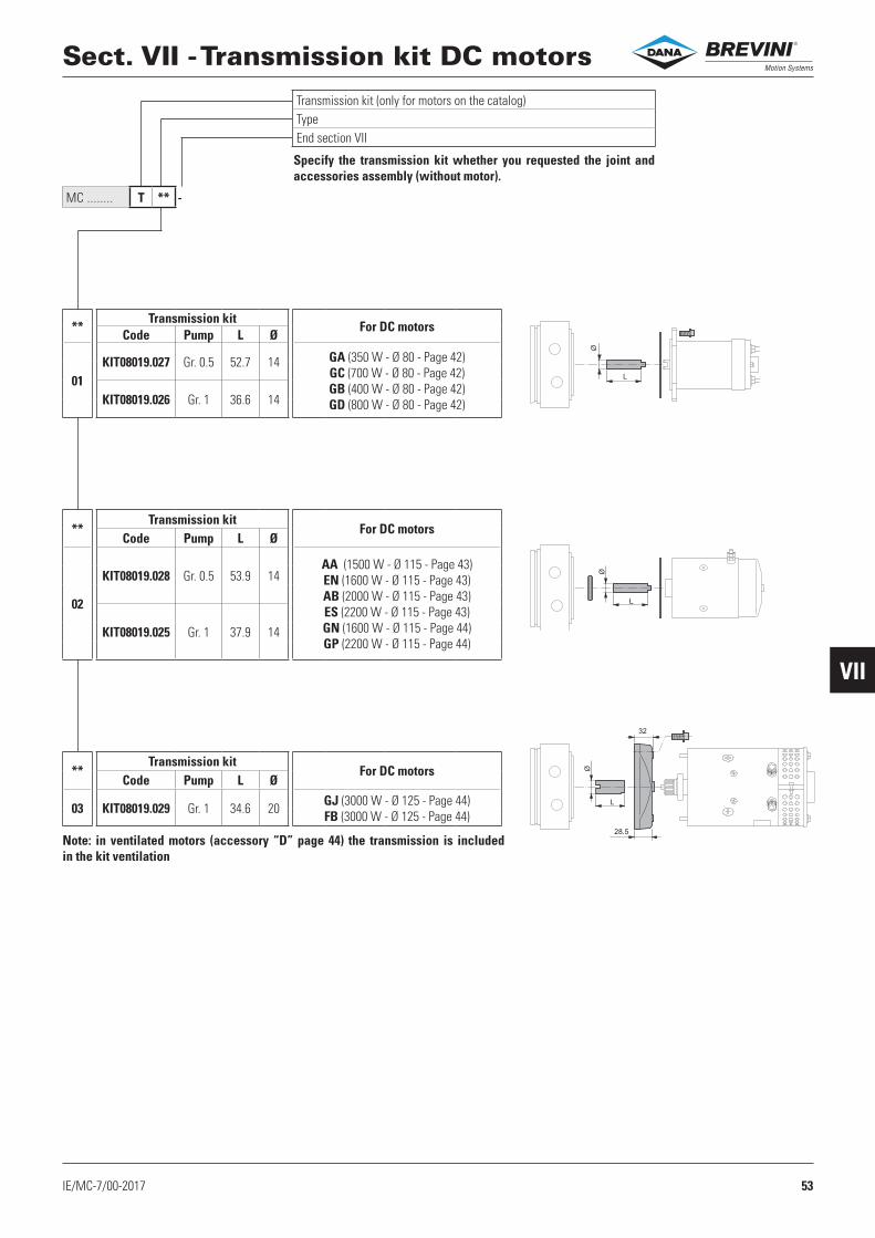
MC ........ T ** -
Ø
L
ØL
Ø
L
32
28.5
Sect. VII - Transmission kit DC motors
Specify the transmission kit whether you requested the joint and accessories assembly (without motor).
Transmission kit (only for motors on the catalog)TypeEnd section VII
Note: in ventilated motors (accessory “D” page 44) the transmission is included in the kit ventilation
**Transmission kit
For DC motorsCode Pump L Ø
01KIT08019.027 Gr. 0.5 52.7 14 GA (350 W - Ø 80 - Page 42)
GC (700 W - Ø 80 - Page 42)GB (400 W - Ø 80 - Page 42)GD (800 W - Ø 80 - Page 42)KIT08019.026 Gr. 1 36.6 14
**Transmission kit
For DC motorsCode Pump L Ø
02
KIT08019.028 Gr. 0.5 53.9 14AA (1500 W - Ø 115 - Page 43)EN (1600 W - Ø 115 - Page 43)AB (2000 W - Ø 115 - Page 43)ES (2200 W - Ø 115 - Page 43)GN (1600 W - Ø 115 - Page 44)GP (2200 W - Ø 115 - Page 44)
KIT08019.025 Gr. 1 37.9 14
**Transmission kit
For DC motorsCode Pump L Ø
03 KIT08019.029 Gr. 1 34.6 20 GJ (3000 W - Ø 125 - Page 44)FB (3000 W - Ø 125 - Page 44)
®

54 IE/MC-7/00-2017
VII
MC ........ T ** -
LL1
Z
Ø Ø 1
1
19.5
L L1
Z
Ø Ø 1
4
19.5
L L1
Ø
Z
Ø 1
9
30.4
L L1
Ø
Z
Ø 2
4
40.4
L1L
Ø
Z
Ø 2
8
75
L
Ø
L
Ø
Sect. VII - Transmission kit AC motors
Specify the transmission kit whether you requested the joint and accessories assembly (without motor).
Transmission kit (only for motors on the catalog)TypeEnd section VII
“Z” : dimension of the coupling side motor
**Transmission kit For AC motors
PageCode Pump L Ø L1 Z Ref. Size
1RKIT01008.008 Gr. 0.5 16 14 49.5 62.7
R 63(B14) 49
KIT01008.014 Gr. 1 19.5 20 30 42.8
**Transmission kit For AC motors
PageCode Pump L Ø L1 Z Ref. Size
1LKIT01008.006 Gr. 0.5 36.1 14 26.5 42
L 71(B14)
48
KIT01008.001 Gr. 1 19.5 20 26.5 42 49
**Transmission kit For AC motors
PageCode Pump L Ø L1 Z Ref. Size
1MKIT01008.005 Gr. 0.5 36.1 14 38 53
M 80(B14)
48
KIT01008.002 Gr. 1 19.5 20 38 53 49
**Transmission kit For AC motors
PageCode Pump L Ø L1 Z Ref. Size
1NKIT01008.007 Gr. 0.5 36.1 14 45.5 63
N 90(B14)
48
KIT01008.003 Gr. 1 19.5 20 45.5 63 49
**Transmission kit For AC motors
PageCode Pump L Ø L1 Z Ref. Size
1PKIT01008.013 Gr. 0.5 52.7 14 57 81.5
P 100-112(B14)
48
KIT01008.004 Gr. 1 36.3 20 57 81.5 49
**Transmission kit For AC motors
PageCode Pump L Ø Ref. Size
1SKIT01008.130 Gr. 0.5 53.9 14
S71
(direct fixing)
50KIT01008.126 Gr. 1 37.9 14
**Transmission kit For AC motors
PageCode Pump L Ø Ref. Size
1T KIT01008.131 Gr. 1 41.5 20 T V 80-90 (direct fixing)
51
®

55IE/MC-8/00-2017
VIII
J 0 J A J B J C
J 0 J A J B J C
MC ... J * (00) -
1
2
3
4
96 (91006000.000)
1
2
3
4
111
.5 (91006001.000)
4 3 2 1
14
0.5 (91006001.000)
(91006000.000)4 3 2 1
1 2 3 4
96
(91006000.000)
1 2 3 4
111.5
(91006001.000)
1
2
3
4
24
140.5
(91006001.000)
(91006000.000)
1
2
3
4
Blocks orthogonal to the axisExcept AC motors ref. size M-N-P
Blocks orthogonal to the axis with heightenFor AC motors ref. size M-N-P
Blocks parallel to the axis with interface 90°Except AC motors ref. size P
Blocks parallel to the axis with heighten and interface 90°For AC motors ref. size P
Sect. VIII - Blocks and CETOP valves
Blocks mounting on horizontal power pack
The blocks can not be mounted with motors oriented in position “1” (DC motors, see page 46. AC motors, see page 52).
Blocks orthogonal to the axisExcept AC motors ref. size M-N-P
Blocks orthogonal to the axis with heightenFor AC motors ref. size M-N-P
Blocks parallel to the axis with interface 90°Except AC motors ref. size P
Blocks parallel to the axis with heighten and interface 90°For AC motors ref. size P
Blocks mounting on vertical power pack
The blocks can not be mounted with motors oriented in position “1” - DC motors, see page 46. AC motors, see page 52.
In the order confirmation the code of the “Blocks and CETOP valves” will be converted into a type Jxxxx (xxxx = sequential number).
The blocks mounting kit (interface 90°, heighten) is included on the selection code (see “Mounting kits “table page 58).
Standard blocks
Mounting position
Accessory
Separation line
®
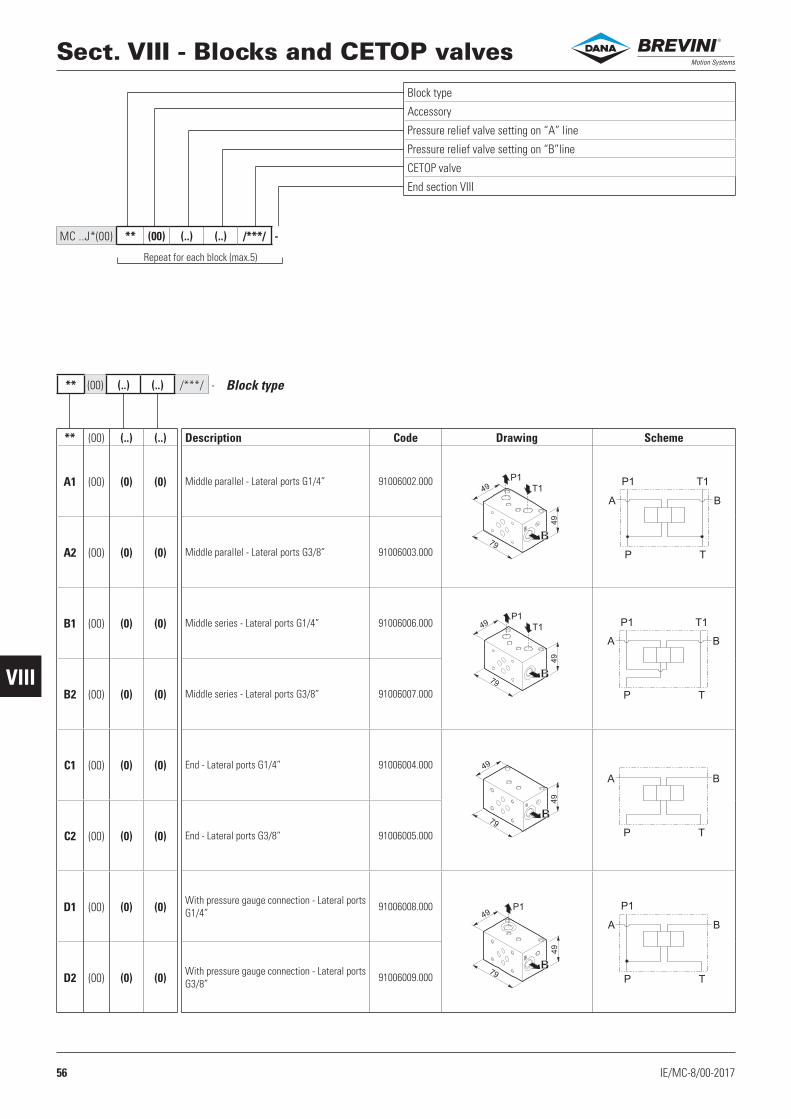
56 IE/MC-8/00-2017
VIII
MC ..J*(00) ** (00) (..) (..) /***/ -
** (00) (..) (..) /***/ -
B
49
79
49 T1
P1
B
49
79
49T1
P1
B
49
79
49
49
79
49
B
P1
A
P
P1
T
T1
B
P1 T1
A
P T
B
A
P T
B
A
P
P1
T
B
Sect. VIII - Blocks and CETOP valves
Block type
Repeat for each block (max.5)
Block type
Accessory
Pressure relief valve setting on “A” line
Pressure relief valve setting on “B”line
CETOP valve
End section VIII
** (00) (..) (..) Description Code Drawing Scheme
A1 (00) (0) (0) Middle parallel - Lateral ports G1/4” 91006002.000
A2 (00) (0) (0) Middle parallel - Lateral ports G3/8” 91006003.000
B1 (00) (0) (0) Middle series - Lateral ports G1/4” 91006006.000
B2 (00) (0) (0) Middle series - Lateral ports G3/8” 91006007.000
C1 (00) (0) (0) End - Lateral ports G1/4” 91006004.000
C2 (00) (0) (0) End - Lateral ports G3/8” 91006005.000
D1 (00) (0) (0) With pressure gauge connection - Lateral ports
G1/4”91006008.000
D2 (00) (0) (0) With pressure gauge connection - Lateral ports
G3/8”91006009.000
®

57IE/MC-8/00-2017
VIII
** (00) (..) (..) /***/ -
49
89
59
B
T1
P1
49
79
65
C
T1
P1
80
40
181
60
max
190
49
85
78.5
B
T1
P1
49
85
79.5
B
T1
P149
85
79.5
B
T1
P1
A
P
P1
T
T1
B
A
P
P1
T
T1
B
A
P
P1
T
T1
B
A
P
P1
T
T1
B
A
P
P1
T
T1
B
A
P
P1
T
T1
B
P
C
P1
T
T1
P1
P
R1 R2
T
Sect. VIII - Blocks and CETOP valves
Block type
** (00) (..) (..) Description Code Drawing Scheme
E1 (00) (0) (0) With pilot check valve on ”A” port
Lateral ports G1/4”91006010.000
E2 (00) (0) (0) With pilot check valve on ”B” port
Lateral ports G1/4”91006011.000
E3 (00) (0) (0) With pilot check valve on ”A” and “B” ports
Lateral ports G1/4”91006012.000
F1 (00)
(A) (0)With pressure relief valve on “A” port
Setting 35 ÷ 90 bar - Lateral ports G1/4”91006013.000
(B) (0) With pressure relief valve on “A” port
Setting 75 ÷ 190 bar - Lateral ports G1/4”91006014.000
(C) (0) With pressure relief valve on “A” port
Setting 160 ÷ 290 bar - Lateral ports G1/4”91006015.000
F2 (00)
(0) (A)With pressure relief valve on “B” port
Setting 35 ÷ 90 bar - Lateral ports G1/4”91006016.000
(0) (B) With pressure relief valve on “B” port
Setting 75 ÷ 190 bar - Lateral ports G1/4”91006017.000
(0) (C) With pressure relief valve on “B” port
Setting 160 ÷ 290 bar - Lateral ports G1/4”91006018.000
F3 (00)
(A) (A)With pressure relief valve on “A” and “B”
Setting 35 ÷ 90 bar - Lateral ports G1/4”91006019.000
(B) (B) With pressure relief valve on “A” and “B”
Setting 75 ÷ 190 bar - Lateral ports G1/4”91006020.000
(C) (C) With pressure relief valve on “A” and “B”
Setting 160 ÷ 290 bar - Lateral ports G1/4”91006021.000
G1 (00) (0) (0)Block No.13 (CRP04 valves to be ordered sepa-
rately, see catalogue code. DOC00044)
Lateral ports G1/4”
91006022.000
K1 (00) (0) (0) End - Hand pump 91006023.000
®

58 IE/MC-8/00-2017
VIII
a b
A
P
B
T
a b
A
P
B
T
a b
A
P
B
T
a b
A
P
B
T
** (00) (..) (..) /***/ -
Sect. VIII - Blocks and CETOP valves
1 = Valves supplied with connector. Without connector see accessories page 59 2 = More details, features and performances, see catalog Dana “Valves and Electronics” code DOC00078
CETOP 3 valves
Mounting kit: blocks For No. blocks Code
Mounting position 0-B-C
1 17070013
2 17070015
3 17070017
4 17070019
Mounting position A (with heighten)
1 17070014
2 17070016
3 17070018
4 17070020
Mounting kit: interface 90° Code
Mounting position B 17070022
Mounting kit: interface 90° with heighten Code
Mounting position C 17070023
Mounting kits
The blocks mounting kit (interface 90°, heighten) is included on the selection code (see mounting position, page 55).
connectors supplied with the valve (1)
/***/ Voltage CodeSpool (2) Screw kit for valve
mounting Type Mounting Scheme
/000/ Without valve
/001/ 24 VDC (M) ADC3E01CM001
01 C
V60513015
/002/ 12 VDC (L) ADC3E01CL001
/003/ 24 VDC (M) ADC3E02CM001
02 C
/004/ 12 VDC (L) ADC3E02CL001
/005/ 24 VDC (M) ADC3E03CM001
03 C
/006/ 12 VDC (L) ADC3E03CL001
/007/ 24 VDC (M) ADC3E04CM001
04 C
/008/ 12 VDC (L) ADC3E04CL001
®

59IE/MC-9/01-2017
IX
Ø 114
101.6
Ø 1
21
264 FORI M6
101.6
125 120
48
n°4 Ø 9
MC ........ R * *
125 125
28
.5
n°4 Ø 11
Sect. IX - AccessoriesAccessories (optional)First accessorySecond accessory
* Description Drawing Code Note
G Standard foot, (galvanized sheet steel)
thickness 2.5 mm (unassembled)
Kit
(foot and screws):
17010021
All motors are compatible
except orientation / 3
Tanks compatible
(except for orientation / 3)
S**A
S**B
S**C
S**G
S**L
B Non-removable red plastic plug for pressure
relief valve (unassembled)
Plug:
60309200
C Protection device for DC motors
(supplied assembled)
Kit
(protectin, nut,
tierods, washers):
17010048
For motors:
M2EN
M4ES
With blocks, please add the
block code 91006000.000
D High foot, (galvanized sheet steel) thickness
2 mm (unassembled)
Kit
(foot and screws):
17010053
All motors are compatible
except orientation / 3
Tanks compatible
(except for orientation / 3)
S**A
S**B
S**C
S**D
S**F
S**G
S**L
E Collar in welded sheet steel, thickness 2 mm
(unassembled)
Collar:
25000300
Tank fixing kit
(screws and O-Ring):
17010086
F Without valves connectors
®

60
MCA 1 A1 A 2DAAA 3FBC -03 - ..
MCA 0 A1 A 2TE 3TN -00 - ..
MCB 1 B1(80) A 2CA 3TJ/G -03 - ..
A1 A
2DAAA3FBC
3 2
1R
4
1
T P
G3/8" G3/8"
A1 A
3 2
1R
4
1
T P
2CA3TJ /G
G3/8" G3/8"
4
A1 A
3 2
1R
4
1
G1/4" G1/4"
AB
P1T1
3TN 2TE
Examples
Examples with MCA endhead
Examples with MCB endhead
Cavity Code Description Page- 1 Thread ports P-T G3/8” 11
1 A1
Pressure relief valve with check valve (15 ÷ 50 bar) with screw and detachable closing, standard setting 50 bar
12
1R A Standard check valve 13
2 2DAAAPiloted solenoid valve normally closed, without emergency. Voltage 12 VDC
15
3 3FBC Unidirectional flow control valve compensated 18
P-T -03 Combinations plugs on ports (P= open ; T= closed) 22
- - End section —
Cavity Code Description Page
- 0 Thread ports P-T G1/4” (blocks interface) 11
1 A1
Pressure relief valve with check valve (15 ÷ 50 bar) with screw and detachable closing, standard setting 50 bar
12
1R A Standard check valve 132 2TE Long plug 3/4 16 UNF - G1/4” 163 3TN Plug 19
P-T -00 Combinations plugs on ports (P= open ; T= open) 22
- - End section —
Cavity Code Description Page- 1 Thread ports P-T G3/8” 11
1 B1Pressure relief valve with check valve with screw and detachable closing, special setting 80 bar
12
1R A Standard check valve 13
2 2CA Lever operated valve without microswitch 15
3 3TJ/G Plug and flow control valve 4.7 l/min 20
P-T -03 Combinations plugs on ports (P= open ; T= closed) 22
- - End section —
®


®
Dana Motion Systems Italia S.r.l.Fluid Power Division
Sede operativa: Via Giulio Natta 1, 42124 Reggio Emilia - Italy Tel: +39.0522.270711 - Fax: +39.0522.505856
Sede legale: Via Luciano Brevini 1/A, 42124 Reggio Emilia - Italy Tel: +39.0522.9281 - Fax: +39.0522.928300
www.dana.com/brevini - [email protected]
Code DOC00084 - Rev. 04