Embed Size (px)
Citation preview

PAGE 1
MC-4210 - CO-F ADDRESSABLE SENSOR
Manual Part Number 180-0567 September 15, 2006
AMERICAN MINE RESEARCH, INC. P. O. BOX 234, ROCKY GAP, VA 24366 PH. 276-928-1712 FAX 276-928-1814

PAGE 2
TABLE OF CONTENTS TITLE PAGE Table of Contents...............................................................................................2 List Of Figures ...................................................................................................4 1. Introduction ...................................................................................................5 1.0. General ............................................................................................5 1.1. Features ...........................................................................................5 1.2. Default Values .................................................................................6 1.3. New Features...................................................................................6 2. Specifications..................................................................................................7 3. Setup ...............................................................................................................9 3.1. DS1 Setup Switch............................................................................9 3.2. DS2 Cell Polarity ............................................................................10 3.3. DS3 2 Wire/4 Wire Comm .............................................................10 3.4. DS4 Comm Enable/Disable............................................................11 3.5. DS5 2 Wire/3 Wire Cell..................................................................11 3.6. DS6 Sensor Mode............................................................................11 3.7. Address Switches ............................................................................11 3.8. Setup Adjust....................................................................................11 3.9. Zero Adjust .....................................................................................11 3.10. Reference Adjust ..........................................................................12 3.11. PGM INIT Port.............................................................................12 4. Configuration.................................................................................................13 4.0. General ............................................................................................13 4.1. Current Loop Mode Sensor (Stand Alone) ..................................13 4.2. Voltage Mode Sensor (Stand Alone) .............................................13 4.3. Monitor System Sensor/Remote ....................................................14 5. Installation......................................................................................................15 5.0. General ............................................................................................15 5.1. Power Connections .........................................................................16 5.1.1. Power Connection (Stand Alone Voltage Mode) ......................17 5.1.2. Power Connection (Voltage Mode in Permissible Area)..........18 5.1.3. Power Connection (Current Loop Mode) .................................19 5.1.4. Power Connection (Current Loop Mode in Permissible Area)20 5.2. Sensor Cell Connection ..................................................................21 5.3. Warn/Alarm Output Connection..................................................21 5.4. Analog Input #1 and Analog Input #2 Connections ....................21

PAGE 3
TABLE OF CONTENTS(CONT.) TITLE PAGE 5.5. Status Input #1 and Status Input #2 Connections.......................22 5.6. Control Output #1 and Control Output #2 Connections ............22 5.7. Calibration/Test Switch Connection.............................................22 5.8. 2-Wire Monitor System Connection .............................................22 5.9. 4-Wire Monitor System Connection .............................................22 5.10. Input/Output Interface PC Board ..............................................25 5.10.1. Remove MC-4210 Terminal Block Board...............................25 5.10.2. Inby/Outby Power Connection.................................................25 5.10.3. Inby/Outby 2-Wire Comm Connection ...................................25 5.10.4. Inby/Outby 4-Wire Comm Connection ...................................26 5.10.5. E1 Thru E7 Wires to Monitor PC Board 253-0355................26 5.10.6. Control Output 0 .......................................................................26 5.10.7. Control Output 1 .......................................................................26 5.10.8. Digital Input 0 ............................................................................27 5.10.9. Digital Input 1 ............................................................................27 5.10.10. Analog Input 0 .........................................................................27 5.10.11. Analog Input 1 .........................................................................27 6. Calibration .....................................................................................................30 6.0. General ............................................................................................30 6.1. Zero Calibration .............................................................................30 6.2. Span Calibration.............................................................................31 7. Testing ............................................................................................................32 7.0. General ............................................................................................32 7.1. Perform Test ...................................................................................33 8. Programming the Flash MC-4210-CO Sensor............................................34 9. Installation Check List ..................................................................................35 10. Replacement Parts.......................................................................................36
PAGE 4
LIST OF FIGURES TITLE PAGE Figure 1, Connection and Configuration Diagram.........................................8 Figure 2, MC-4210-CO Monitor Connections ................................................16 Figure 3, Stand Alone Voltage Mode Connection to Monitor System..........17 Figure 4, Stand Alone Voltage Mode Sensor in Permissible Area................18 Figure 5, Stand Alone Current Loop Mode Connection…………………….19 Figure 6, Stand Alone Current Loop Mode Sensor in Permissible Area .....20 Figure 7, MC-4210 (2 Wire Addressable Sensor)...........................................23 Figure 8, 2 Wire Addressable Monitor Thru Barriers ..................................23 Figure 9, MC-4210 (4 Wire Addressable Sensor)...........................................24 Figure 10, 4 Wire Addressable Monitor Thru Barriers ................................24 Figure 11, Input/Output Interface PC Board Connections ...........................28 Figure 12, Input/Output Interface PC Board Connections ...........................29 Figure 13, Flash Sensor Programmer Connections........................................34

PAGE 5
1. INTRODUCTION 1.0. General The American Mine Research Flash MC-4210-CO Addressable Sensor is a compact monitor designed to be used with the AMR Mine Wide Monitoring System. Available in a varity of gases, it has the traditional AMR quality construction, leading edge technology and maintenance free characteristics. The Flash MC-4231-CO Sensor has the same electronics as the MC-4210-CO Sensor with the addition of audible and visual alarms. The Flash sensor firmware can easily be modified at the installation site to add new features. 1.1. Features The features of the Flash MC-4210-CO Sensor are summarized below:
• Firmware programmable in the field • Firmware version displayed on boot-up and during “Test” • Sensor self testing proper operation • Available also as NO, NO2, O2, SO2, H2S, H2 sensor • Stand Alone Voltage or Current Mode Operation • May be used in areas with like type classification barriers • Low current operation: Less than 6 ma. in voltage mode • High speed data rate: Standard 19.2K baud • 4 Digit LCD Display • Magnetically activated test and calibration switch (can be calibrated without
removing the cover) • Microprocessor controlled calibration (no potentiometers to adjust) • Smart operation: testing and calibration does not set off outside alarms. • Alarm and Warning outputs adjustable • Optional Zero Offset • Valid communications with Master Station indication • Sealed polycarbonate enclosure • Highly visible 360 degree strobe light (Flash MC-4231-CO Modbus) • 103 decibel Sonalert (R)(Flash MC-4231-CO Modbus) • Uses City Technology sensor cells • MSHA Classification (Pending) • Optional Input/Output Interface PC Board available

PAGE 6
1.2. Default Values The unit is shipped from the factory with the following default settings:
• Output mode: Voltage • Full-scale value: 50PPM • Calibration gas : 50PPM • Test value: 50PPM • Warning level: 10PPM • Alarm level: 15 PPM • Zero Offset: 0 PPM (Zero Offset is optional and provided for some users)
1.3. New Features The American Mine Research Flash MC-4210-CO Sensor has all the features of the earlier MC-4210 model plus several important features have been included. Listed below are the new features of the Flash MC-4210-CO Sensor.
• Sensor firmware may be changed in the field • Sensor firmware version displayed on boot-up and during “Test” • Sensor Span, Warn and Alarm memory values are tested during boot-up • Sensor Cal/Test Switch is continuously tested for proper operation • Sensor checks to insure the CO sensor cell is connected • Sensor periodically verifies proper response to a simulated rise in CO.
PAGE 7
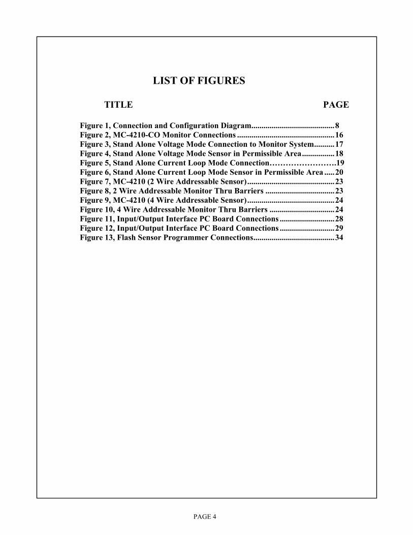
2. SPECIFICATIONS
• Size: 7”W x 7”H x 5”D • Operating Voltage: +10VDC to +28VDC • Operating Mode: Voltage Mode or Current (4-20mA) Mode • Operating Current: Voltage Mode = 6.0mA. • Operating Current: Addressable Sensor = 8.5mA • Voltage Mode Output: 0.1 volts for 0 ppm • Voltage Mode Output: 4.0 volts for 50 ppm • Full Scale Range: Dip Switch Selectable, 25 ppm or 50 ppm • Calibration Gas: Dip Switch Selectable, 25 ppm or 50 ppm • Display: Four Digit LCD • Detection Principle: Diffusion Type Electro-chemical • Trip Outputs: Open Collector Current sink 100mA • Warn, Alarm Trip Level: User Adjustable • Zero Offset Level User Adjustable (Provided for some users)
• Communication Interface: 2 Wire or 4 Wire RS-485 • Communication Baud Rate: 38400 baud, standard
PAGE 8
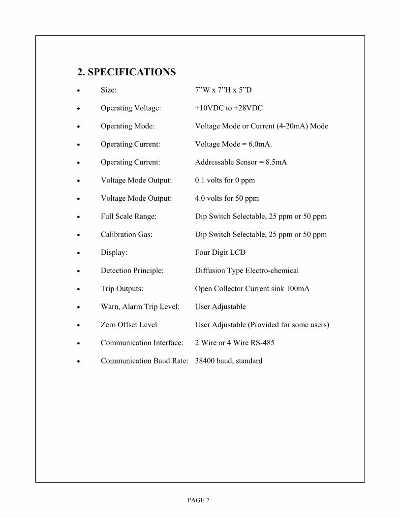
FIGURE 1, CONNECTION AND CONFIGURATION DIAGRAM
PAGE 9
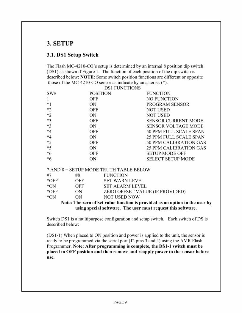
3. SETUP 3.1. DS1 Setup Switch The Flash MC-4210-CO’s setup is determined by an internal 8 position dip switch (DS1) as shown if Figure 1. The function of each position of the dip switch is described below: NOTE: Some switch position functions are different or opposite those of the MC-4210-CO sensor as indicate by an asterisk (*).
DS1 FUNCTIONS SW# POSITION FUNCTION 1 OFF NO FUNCTION *1 ON PROGRAM SENSOR *2 OFF NOT USED *2 ON NOT USED *3 OFF SENSOR CURRENT MODE *3 ON SENSOR VOLTAGE MODE *4 OFF 50 PPM FULL SCALE SPAN *4 ON 25 PPM FULL SCALE SPAN *5 OFF 50 PPM CALIBRATION GAS *5 ON 25 PPM CALIBRATION GAS *6 OFF SETUP MODE OFF *6 ON SELECT SETUP MODE 7 AND 8 = SETUP MODE TRUTH TABLE BELOW #7 #8 FUNCTION *OFF OFF SET WARN LEVEL *ON OFF SET ALARM LEVEL *OFF ON ZERO OFFSET VALUE (IF PROVIDED) *ON ON NOT USED NOW Note: The zero offset value function is provided as an option to the user by using special software. The user must request this software. Switch DS1 is a multipurpose configuration and setup switch. Each switch of DS is described below: (DS1-1) When placed to ON position and power is applied to the unit, the sensor is ready to be programmed via the serial port (J2 pins 3 and 4) using the AMR Flash Programmer. Note: After programming is complete, the DS1-1 switch must be placed to OFF position and then remove and reapply power to the sensor before use.

PAGE 10
3.1. DS1 Setup Switch (Cont.) (DS1-2) Not Used. (DS1-3) Selects sensor output mode. OFF= current , ON= voltage. Note: 1) The voltage mode should be used if the sensor is an addressable type. 2) Voltage mode output of 0.1 volts represents 0 PPM and 4.0 volts represents 50 PPM full scale. 3) Current mode output of 4 mA represents 0 PPM and 20 mA represents 50 PPM. 4) DS6 must match DS1-3 mode selection. (DS1-4) Selects sensor full scale span range. OFF= 50 PPM, ON=25 PPM (DS1-5) Selects sensor calibration gas value OFF = 50 PPM, ON= 25 PPM (DS1-6) Enables the sensor setup mode to allow setting the warn and alarm levels using the setup potentiometer (R15). OFF= SETUP MODE OFF, ON= SETUP MODE ENABLED. (DS1-7,8) These two switches are used according to the truth table above to select the warn or alarm value that is to be set using the SETUP potentiometer (R15). To set one of these values, place DS1-6 switch to the ON position. The display will now read the current value given by the Setup Adjust potentiometer(Figure1). The value indicated will be the previously used position of the Setup Adjust potentiometer, not necessarily the value of the currently selected parameter. Next, configure switches DS1-7,8 according to the above table. Using a small screwdriver, adjust potent- iometer R15 until the desired value is displayed. Now briefly activate the test/calibrate switch. The display will blink the setup value three times indicating that the displayed value has been saved. You may now select another parameter to set using the same procedure. After all the values have been set, return the DS1-6 switch position to OFF. 3.2. DS2 Cell Polarity DS2 is for FACTORY USE ONLY. It is used to match the sensor cell polarity for each gas in the Flash MC-4210 series. 3.3. DS3 2 Wire/4 Wire Comm DS3 allows the Flash MC-4210 to operate with either a 2 wire monitor system interface such as the MC-4000 system or a 4 wire monitor system.
PAGE 11
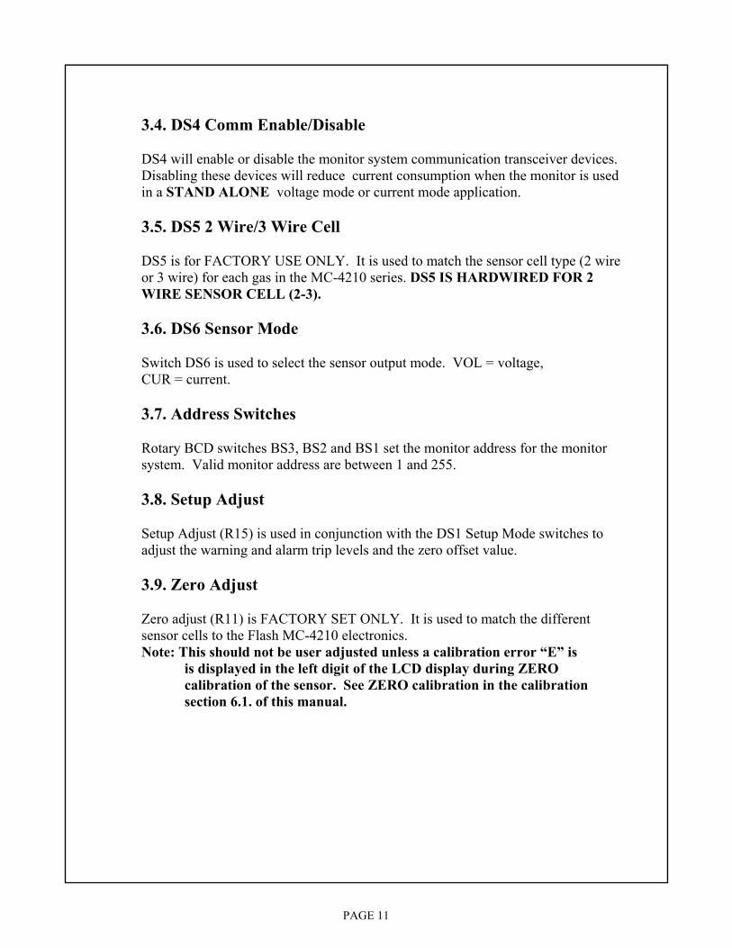
3.4. DS4 Comm Enable/Disable DS4 will enable or disable the monitor system communication transceiver devices. Disabling these devices will reduce current consumption when the monitor is used in a STAND ALONE voltage mode or current mode application. 3.5. DS5 2 Wire/3 Wire Cell DS5 is for FACTORY USE ONLY. It is used to match the sensor cell type (2 wire or 3 wire) for each gas in the MC-4210 series. DS5 IS HARDWIRED FOR 2 WIRE SENSOR CELL (2-3). 3.6. DS6 Sensor Mode Switch DS6 is used to select the sensor output mode. VOL = voltage, CUR = current. 3.7. Address Switches Rotary BCD switches BS3, BS2 and BS1 set the monitor address for the monitor system. Valid monitor address are between 1 and 255. 3.8. Setup Adjust Setup Adjust (R15) is used in conjunction with the DS1 Setup Mode switches to adjust the warning and alarm trip levels and the zero offset value. 3.9. Zero Adjust Zero adjust (R11) is FACTORY SET ONLY. It is used to match the different sensor cells to the Flash MC-4210 electronics. Note: This should not be user adjusted unless a calibration error “E” is is displayed in the left digit of the LCD display during ZERO calibration of the sensor. See ZERO calibration in the calibration section 6.1. of this manual.

PAGE 12
3.10. Reference Adjust Reference Adjust (R32) is FACTORY SET ONLY. It is used in to match the different types of sensor cells to the Flash MC-4210 electronics. Note: This should not be user adjusted. 3.11. PGM INIT Port The PGM INIT Port (J6) is used to initialize the Flash Sensor memory to allow the memory to be programmed with the sensor application firmware. It is for factory use only.
PAGE 13
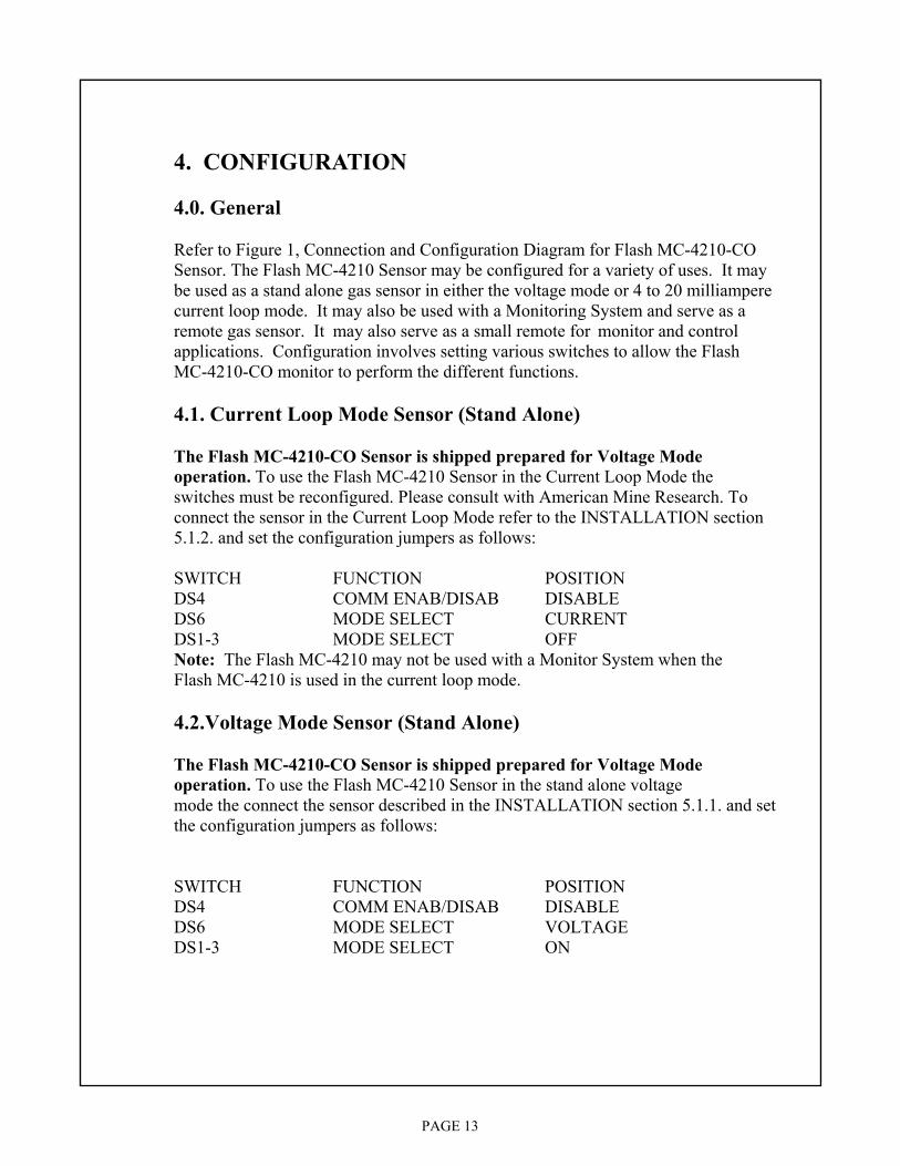
4. CONFIGURATION 4.0. General Refer to Figure 1, Connection and Configuration Diagram for Flash MC-4210-CO Sensor. The Flash MC-4210 Sensor may be configured for a variety of uses. It may be used as a stand alone gas sensor in either the voltage mode or 4 to 20 milliampere current loop mode. It may also be used with a Monitoring System and serve as a remote gas sensor. It may also serve as a small remote for monitor and control applications. Configuration involves setting various switches to allow the Flash MC-4210-CO monitor to perform the different functions. 4.1. Current Loop Mode Sensor (Stand Alone) The Flash MC-4210-CO Sensor is shipped prepared for Voltage Mode operation. To use the Flash MC-4210 Sensor in the Current Loop Mode the switches must be reconfigured. Please consult with American Mine Research. To
connect the sensor in the Current Loop Mode refer to the INSTALLATION section 5.1.2. and set the configuration jumpers as follows: SWITCH FUNCTION POSITION DS4 COMM ENAB/DISAB DISABLE DS6 MODE SELECT CURRENT DS1-3 MODE SELECT OFF Note: The Flash MC-4210 may not be used with a Monitor System when the
Flash MC-4210 is used in the current loop mode. 4.2.Voltage Mode Sensor (Stand Alone) The Flash MC-4210-CO Sensor is shipped prepared for Voltage Mode operation. To use the Flash MC-4210 Sensor in the stand alone voltage mode the connect the sensor described in the INSTALLATION section 5.1.1. and set the configuration jumpers as follows: SWITCH FUNCTION POSITION DS4 COMM ENAB/DISAB DISABLE DS6 MODE SELECT VOLTAGE DS1-3 MODE SELECT ON
PAGE 14
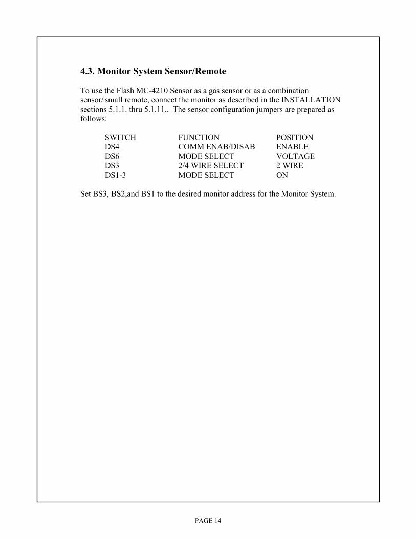
4.3. Monitor System Sensor/Remote To use the Flash MC-4210 Sensor as a gas sensor or as a combination sensor/ small remote, connect the monitor as described in the INSTALLATION sections 5.1.1. thru 5.1.11.. The sensor configuration jumpers are prepared as follows: SWITCH FUNCTION POSITION DS4 COMM ENAB/DISAB ENABLE DS6 MODE SELECT VOLTAGE DS3 2/4 WIRE SELECT 2 WIRE DS1-3 MODE SELECT ON Set BS3, BS2,and BS1 to the desired monitor address for the Monitor System.
PAGE 15
5. INSTALLATION 5.0. General The Flash MC-4210-CO Sensor may be installed in a variety of configurations to solve almost any gas sensor requirements. The monitor may be used in a Stand Alone 4 to 20 milliampere current loop output mode or a Stand Alone 0 to 4 VDC voltage output mode. When used in the voltage output mode, the monitor may also be connected to a Monitoring System 2 wire or a 4 wire RS-485 hardware interface. The monitor may be used in permissible areas in both the voltage and current loop mode by using barriers that have the same classification. When used with a PLC Monitoring System via 2 wire or 4 wire RS-485 hardware interface, the sensor may be placed in permissible areas by using barriers that have the same classification. The monitor may also be used as a monitoring system small remote. In addition to the 100 milliampere current sink type Warning and Alarm outputs, the monitor has two more 100 milliampere current sink type outputs triggered by the two digital status inputs. The two digital status inputs accept 0 to 5 VDC and trigger the control outputs at 2.5 VDC. The digital status information is sent to the PLC Monitor System Master Station. The monitor will also accept two analog voltage inputs and send this information to the Monitoring System Master Station. The analog voltage range is 0 to 5 VDC. The monitor may also serve as a small remote by configuring it with an optional Input/Output Interface PC Board that will allow monitor and control of the following devices:
• control 2 each 115 VAC or 28 VDC at 3 amperes circuits • monitor 2 each 115 VAC or 28 VDC circuits • monitor 2 each 0 to 5 VDC or (4 to 20 mA current loops) analog inputs Note: When the optional Input/Output Interface PC Board is used, the MSHA sensor classification is void.
PAGE 16
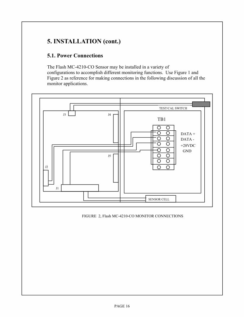
5. INSTALLATION (cont.) 5.1. Power Connections The Flash MC-4210-CO Sensor may be installed in a variety of configurations to accomplish different monitoring functions. Use Figure 1 and Figure 2 as reference for making connections in the following discussion of all the monitor applications.
TEST/CAL SWITCH
SENSOR CELL
DATA + DATA - +28VDC GND
FIGURE 2, Flash MC-4210-CO MONITOR CONNECTIONS
J1
J2
J3 J4
J5
TB1
PAGE 17
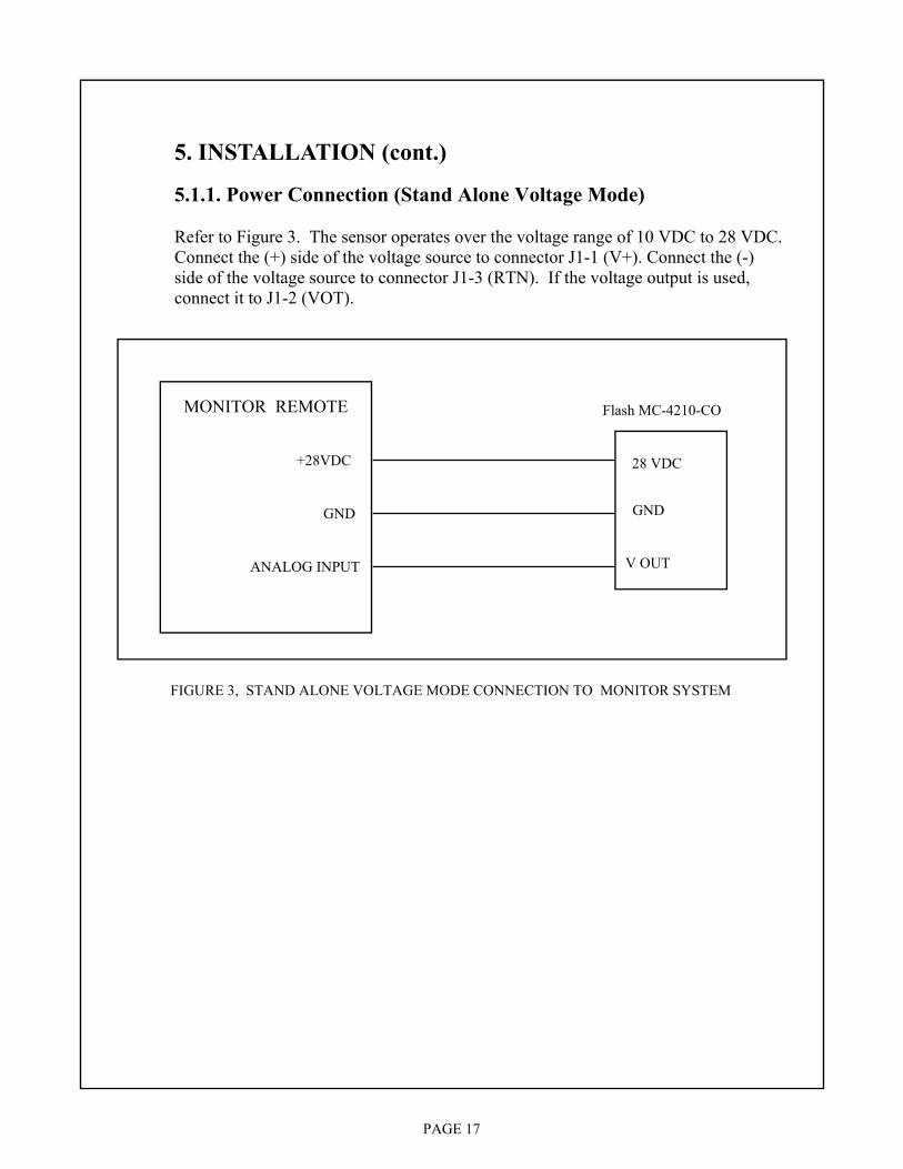
5. INSTALLATION (cont.) 5.1.1. Power Connection (Stand Alone Voltage Mode) Refer to Figure 3. The sensor operates over the voltage range of 10 VDC to 28 VDC. Connect the (+) side of the voltage source to connector J1-1 (V+). Connect the (-) side of the voltage source to connector J1-3 (RTN). If the voltage output is used, connect it to J1-2 (VOT).
FIGURE 3, STAND ALONE VOLTAGE MODE CONNECTION TO MONITOR SYSTEM
Flash MC-4210-CO
V OUT
28 VDC
GND
MONITOR REMOTE
ANALOG INPUT
GND
+28VDC
PAGE 18
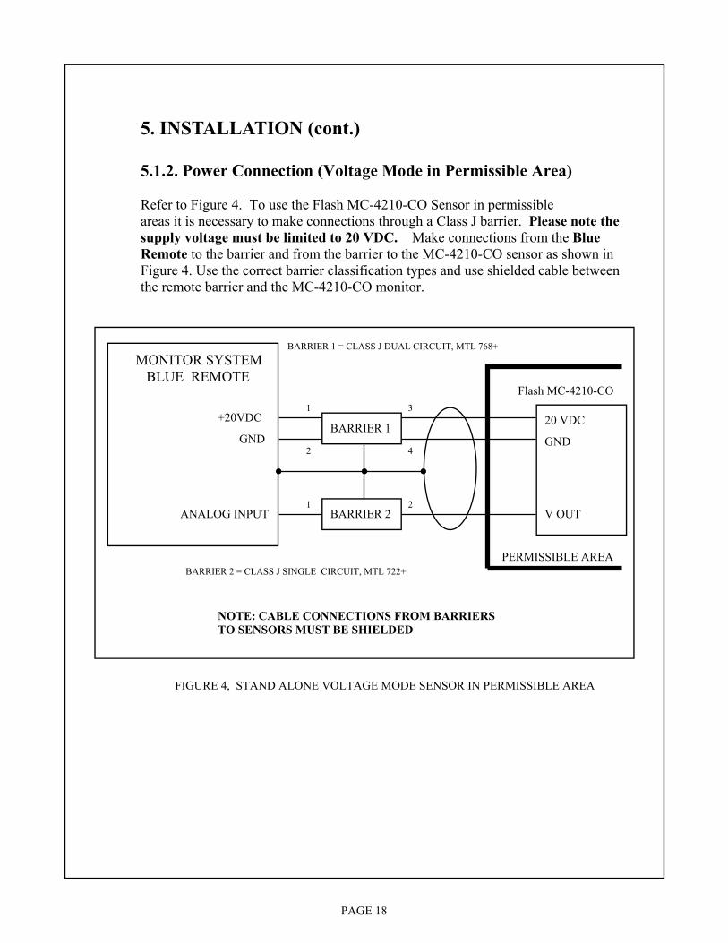
5. INSTALLATION (cont.) 5.1.2. Power Connection (Voltage Mode in Permissible Area) Refer to Figure 4. To use the Flash MC-4210-CO Sensor in permissible areas it is necessary to make connections through a Class J barrier. Please note the supply voltage must be limited to 20 VDC. Make connections from the Blue Remote to the barrier and from the barrier to the MC-4210-CO sensor as shown in Figure 4. Use the correct barrier classification types and use shielded cable between the remote barrier and the MC-4210-CO monitor.
FIGURE 4, STAND ALONE VOLTAGE MODE SENSOR IN PERMISSIBLE AREA
Flash MC-4210-CO
V OUT
20 VDC
GND
MONITOR SYSTEM BLUE REMOTE
ANALOG INPUT
GND
+20VDC BARRIER 1
BARRIER 2
PERMISSIBLE AREA
NOTE: CABLE CONNECTIONS FROM BARRIERS TO SENSORS MUST BE SHIELDED
BARRIER 2 = CLASS J SINGLE CIRCUIT, MTL 722+
BARRIER 1 = CLASS J DUAL CIRCUIT, MTL 768+
1
2
3
4
1 2

PAGE 19
5. INSTALLATION (cont.) 5.1.3. Power Connection (Current Mode) Refer to Figure 5. The sensor operates over the voltage range of 10 VDC to 28 VDC. Connect the (+) side of the voltage source to connector J1-1 (V+). Connect the top side of the current loop monitor resistor to J1-3 (RTN). Connect the bottom side of the current loop monitor resistor the (-) side of the voltage source. Note: VOT is not used in the current loop mode.
FIGURE 5, STAND ALONE CURRENT LOOP MODE CONNECTION TO MONITOR SYSTEM
Flash MC-4210-CO
28 VDC
GND
MONITOR REMOTE
ANALOG INPUT
GND
+28VDC
100 OHMS

PAGE 20
5. INSTALLATION (cont.) 5.1.4. Power Connection (Current Loop Mode in Permissible Area) Refer to Figure 6. To use the Flash MC-4210-CO Sensor in permissible areas it is necessary to make connections through a Class J barrier. Please note the supply voltage must be limited to 20 VDC. Make connections from the Blue Remote to the barrier and from the barrier to the MC-4210-CO monitor as shown in Figure 6. Use the correct barrier classification types and use shielded cable between the remote barrier and the Flash MC-4210-CO monitor.
FIGURE 6, STAND ALONE CURRENT LOOP MODE SENSOR IN PERMISSIBLE AREA
Flash MC-4210-CO
20 VDC
GND
MONITOR BLUE REMOTE
ANALOG INPUT
GND
100 OHMS
BARRIER 1
PERMISSIBLE AREA
NOTE: CABLE CONNECTIONS FROM BARRIERS TO SENSORS MUST BE SHIELDED
BARRIER 1 = CLASS J DUAL CIRCUIT, MTL 768+
20 VDC 1
2
3
4

PAGE 21
5. INSTALLATION (cont.) 5.2. Sensor Cell Connection The Flash MC-4210-CO Sensor may be connected to either 2 wire or 3 wire City Technology sensor cells. For 2 wire cells, connect the SENSE (white/black wire) to J1-4 (SEN) and connect the COUNTER (white/red wire) to J1-6 (CTR). Note: The REF is not used with the 2 wire sensor cell. Note: Jumper DS5 is hardwired to 2 wire (2-3). For 3 wire cells, connect the SENSE (white/black wire) to J1-4 (SEN). Connect the REFERENCE (white wire) to J1-5 (REF) and connect the COUNTER (white/red wire) to J1-6 (CTR). Note: Jumper DS5 must be changed to 3 wire (1-4). 5.3. Warn/Alarm Output Connection The warning and alarm outputs are used to provide audible/visual outputs to indicate the monitor preset levels have been exceeded or they may be used to perform some control function (close door, start device) when these preset levels have been exceeded. Connect the (+) side of the device to be controlled to the (+) side of the power source (+ 28 VDC or less). Connect the (-) side of the device to be controlled to either J1-7(WRN) or J1-8 (ALM). Connect the RETURN of the power source to J1-3 (RTN) of the Flash MC-4210. Note: The current requirement of the device to be controlled can not exceed 100 milliamperes. 5.4. Analog Input # 1 and Analog Input # 2 Connection When the Flash MC-4210-CO monitor is used with the PLC Monitor System, it may be connected to other sensors or transducers that provide a voltage output of 0 to +3 VDC or a 4 to 20 current mode output. The monitor will convert the analog input signal and send the value back to the Monitor System Master Station. Analog input # 1 is connected between J4-3(+) and J4-4 (-). Analog # 2 is connected between J4-5 (+) and J4-6(-). If the input is from a voltage mode sensor, connect the (+) voltage output and the (-) return to the connector as defined above. If the input is from a current mode sensor, connect the current loop monitor resistor across the J4 (+) and (-) connections as defined above.

PAGE 22
5. INSTALLATION (cont.) 5.5. Status Input # 1 and Status Input # 2 Connection The Flash MC-4210-CO may be used to monitor digital (ON/OFF) status signals to perform output control functions (start/stop pump as a function of water level). When the Flash MC-4210-CO monitor is used with the Monitor System, it may be used as a small remote to monitor and control digital (ON/OFF) signals. The status input voltage must be in the range of 0 to 5 VDC. Status input #1 is connected between J5-1(+) and J5-2 (-). Status input #2 is connected between J5-3 (+) and J5-4 (-). 5.6. Control Output # 1 and Control Output # 2 Connection The Flash MC-4210 the monitor has two 100 milliampere current sink type outputs that are triggered by the two digital status inputs. These outputs may be used in conjunction with an interface relay to perform heavy duty control applications (start/stop pump as a function of water level). Connect the (+) side of the device to be controlled to the (+) side of the power source (+28 VDC or less). Connect the (-) side of the device to be controlled to either J5-5 (#1 output) or J5-7 (# 2 output). Connect the RETURN of the power source to either J5-6 (#1 output) or J5-8 (# 2 output). 5.7. Calibration/Test Switch Connection Connect the magnetically activated reed switch used for calibrating and testing the Flash MC-4210 to connector J3. 5.8. 2-Wire Monitor System Connection If the Flash MC-4210 is used either as a gas sensor or as a small remote with the Monitor System it must be connected to the RS-485 communication date line using the 2 wire connection scheme as shown in Figure 7. Connect the data (+) (TB1-1) wire to J2-3 and data (-) (TB1-2) wire to J2-4. 5. 9. 4-Wire Monitor System Connection If the Flash MC-4210 is used either as a gas sensor or as a small remote with a 4 wire monitor system it must be connected to the RS-485 communication data line using the 4 wire connection scheme shown in Figure 9. Connect the Master Station TX(+) (TB1-1) wire to J2-1 and TX(-)(TB1-2) wire to J2-2. Connect the Master Station RX(+) wire to J2-3 and RX(-) wire to J2-4. Connect +28VDC (TB1-5) to J1-1 and GND (TB1-6) to J1-3.

PAGE 23
TEST/CAL SWITCH
SENSOR CELL
DATA + DATA - +28VDC GND
FIGURE 7, Flash MC-4210 (2 WIRE ADDRESSABLE
J1
J2
J3 J4
J5
TB1
FIGURE 8, 2 WIRE ADDRESSABLE MONITOR THRU BARRIERS
BLUE REMOTE
DATA LINE
20 VDC BARRIER 1
BARRIER 2
Flash MC-4210-CO 1
2
3
4
1
2
3
4
DATA LINE
20 VDC
BARRIER 1, 2 = CLASS J DUAL CIRCUIT, MTL 768+
NOTE: CABLE CONNECTIONS FROM BARRIERS TO SENSORS MUST BE SHIELDED
12 AWG GND WIRE MINIMUM
PERMISSIBLE AREA

PAGE 24
SENSOR CELL
TX + TX -
+28VDC GND
FIGURE 9, Flash MC-4210 (4 WIRE ADDRESSABLE
J1
J2
J3 J4
J5
RX + RX -
TEST/CAL SWITCH
TB1
FIGURE 10, 4 WIRE ADDRESSABLE MONITOR THRU BARRIERS
BLUE REMOTE
TX LINE
20 VDC BARRIER 1
BARRIER 2
Flash MC-4210-CO
1
2
3
4
1
2
3
4
RX LINE
20 VDC
BARRIER 1,2 ,3 = CLASS J DUAL CIRCUIT, MTL 768+
NOTE: CABLE CONNECTIONS FROM BARRIERS TO SENSORS MUST BE SHIELDED
12 AWG GND WIRE MINIMUM
RX LINE BARRIER 3
1
2
3
4
TX LINE
PERMISSIBLE AREA
PAGE 25
5. INSTALLATION (cont.) 5. 10. Input/Output Interface PC Board The Flash MC-4210-CO monitor may also serve as a small remote by configuring it with an optional Input/Output Interface PC Board that will allow monitor and control of the following devices:
1) control 2 each 115 VAC or 28 VDC at 3 amperes circuits 2) monitor 2 each 115 VAC or 28 VDC circuits 3) monitor 2 each 0 to 5 VDC or (4 to 20 mA current loops) analog inputs Note: When the optional Input/Output Interface PC Board is used, the MSHA sensor classification is void.
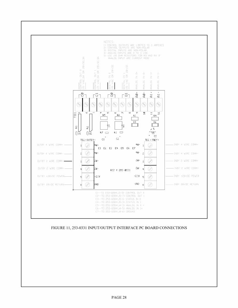
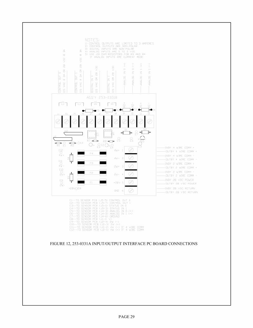
5.10.1. Remove Flash MC-4210-CO Terminal Block Board The Input/Output Interface PC Board fits the same mounting holes as the terminal block board installed in the bottom of the Flash MC-4210-CO monitor. Remove power from the monitor and disconnect all wires from the terminal block board. Remove the the terminal block board and replace it with the Input/Output Interface PC Board. 5.10.2. Inby/Outby Power Connection Refer to Figure 11 if the interface pc board assembly is 253-0331 and connect the wires that provide +28 VDC and Ground to power to inby monitors and remotes to TB3 positions 5 and 6 respectively. Connect the wires from outby the monitor that provide +28 VDC and Ground to power the monitor to TB2 positions 5 and 6 respectively. Refer to Figure 12 if interface pc board assembly is 253-0331A and connect the wires that provide +28 VDC and Ground to power to inby and outby monitors and remotes to TB2 positions 5 and 6 respectively. 5.10.3. Inby/Outby 2 - Wire Comm Connection Refer to Figure 11 if the interface pc board assembly is 253-0331. For the 2 - wire PLC Monitor System communication line, connect the inby comm (+) and comm (-) to TB3 positions 3 and 4 respectively. Connect the wires from outby the monitor that provide comm (+) and comm (-) to the monitor to TB2 positions 3 and 4 respectively. Refer to Figure 12 if the interface pc board assembly is 253-0331A . For the 2 - wire Monitor System communication line, connect the inby and outby comm (+) and comm (-) to TB2 positions 3 and 4 respectively.

PAGE 26
5. INSTALLATION (cont.) 5.10.4. Inby/Outby 4 - Wire Comm Connection Refer to Figure 11 of the interface pc board assembly is 253-0331. For the 4 - wire monitor system communication line, connect the inby comm (+) and comm (-) to TB3 positions 1 and 2 respectively. Connect the wires from outby the monitor that provide comm (+) and comm (-) to the monitor to TB2 positions 1 and 2 respectively. Refer to Figure 12 if the interface pc board assembly is 253-0331A. For the 4 - wire monitor system communication line, connect the inby and outby comm (+) and comm (-) to TB3 positions 1 and 2 respectively. 5.10.5. E1 - E12 Wires to Monitor PC Board 253-0355 Refer to Figures 11 and 12. Connect wires E1 thru E7 to the monitor pc board assembly 253-0355 as follows: E1 to J5-5 Control Output 0 E8 to J1-1 V+ E2 to J5-7 Control Output 1 E9 to J2-4 2W Comm (-) E3 to J5-1 Digital Input 0 E10 to J2-3 2W Comm (+) E4 to J5-3 Digital Input 1 E11 to J2-2 4W Comm (-) if used E5 to J4-3 Analog Input 0 E12 to J2-1 4W Comm (+) if used E6 to J4-5 Analog Input 1 E7 to J4-6 Ground 5.10.6. Control Output 0 Refer to Figures 11 and 12. The load that is to be controlled by output 0 may be powered either by 115 VAC or 28 VDC. The load current must be less than 3 amperes. The control device is an isolated bi-directional solid state switch so polarity is not important. Connect the device to be controlled to TB1 positions 1 and 2. 5.10.7. Control Output 1 Refer to Figures 11 and 12. The load that is to be controlled by output 1 may be powered either by 115 VAC or 28 VDC. The load current must be less than 3 amperes. The control device is an isolated bi-directional solid state switch so polarity is not important. Connect the device to be controlled to TB1 positions 3 and 4.
PAGE 27
5. INSTALLATION (cont.) 5.10.8. Digital Input 0 Refer to Figures 11 and 12. Digital Input 0 is typically connected across a contact that is controlling a 115 VAC device or 28 VDC device. A bi-directional input opto- coupler is used on the interface pc board to monitor the presence of voltage. Polarity is not important. Connect the device or contact to be monitored to TB1 positions 5 and 6. 5.10.9. Digital Input 1 Refer to Figures 11 and 12. Digital Input 1 is typically connected across a contact that is controlling a 115 VAC device or 28 VDC device. A bi-directional input opto- coupler is used on the interface pc board to monitor the presence of voltage. Polarity is not important. Connect the device or contact to be monitored to TB1 positions 7 and 8. 5.10.10. Analog Input 0 Refer to Figures 11 and 12. Analog input 0 may be either from a 0 to 3 VDC voltage source or a 4 to 20 mA current loop source. If the analog input is from a voltage source, remove the 100 ohm termination resistor R3. If the analog input is from a current source, insure that the 100 ohm termination resistor R3 is installed. Connect analog input 0 (+) to TB1-9 and analog input 0 (-) to TB1-10. The analog input signal device may be powered from the same +28 VDC that powers the MC-4210- CO monitor. 5.10.11. Analog Input 1 Refer to Figures11 and 12. Analog input 1 may be either from a 0 to 3 VDC voltage source or a 4 to 20 mA current loop source. If the analog input is from a voltage source, remove the 100 ohm termination resistor R4. If the analog input is from a current source, insure that the 100 ohm termination resistor R4 is installed. Connect analog input 0 (+) to TB1-11 and analog input 0 (-) to TB1-12. The analog input signal device may be powered from the same +28 VDC that powers the MC-4210- CO monitor.
PAGE 28
FIGURE 11, 253-0331 INPUT/OUTPUT INTERFACE PC BOARD CONNECTIONS
PAGE 29
FIGURE 12, 253-0331A INPUT/OUTPUT INTERFACE PC BOARD CONNECTIONS
PAGE 30
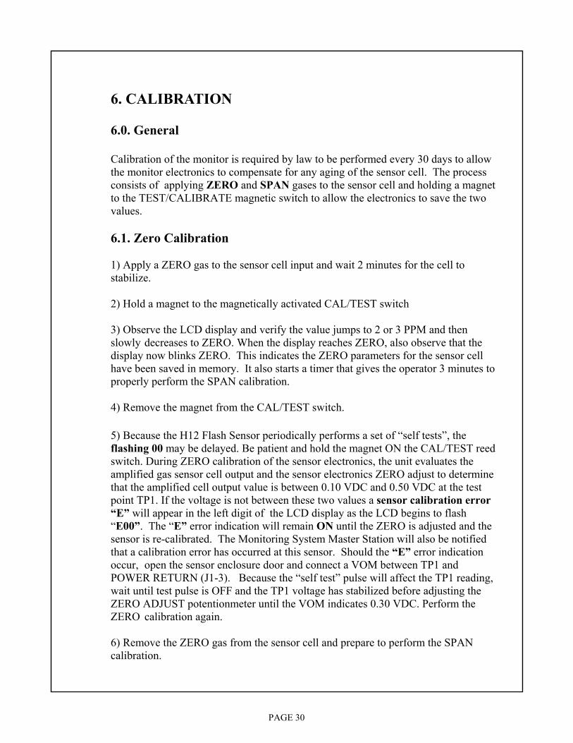
6. CALIBRATION 6.0. General Calibration of the monitor is required by law to be performed every 30 days to allow the monitor electronics to compensate for any aging of the sensor cell. The process consists of applying ZERO and SPAN gases to the sensor cell and holding a magnet to the TEST/CALIBRATE magnetic switch to allow the electronics to save the two values. 6.1. Zero Calibration 1) Apply a ZERO gas to the sensor cell input and wait 2 minutes for the cell to stabilize. 2) Hold a magnet to the magnetically activated CAL/TEST switch 3) Observe the LCD display and verify the value jumps to 2 or 3 PPM and then slowly decreases to ZERO. When the display reaches ZERO, also observe that the display now blinks ZERO. This indicates the ZERO parameters for the sensor cell have been saved in memory. It also starts a timer that gives the operator 3 minutes to properly perform the SPAN calibration. 4) Remove the magnet from the CAL/TEST switch. 5) Because the H12 Flash Sensor periodically performs a set of “self tests”, the flashing 00 may be delayed. Be patient and hold the magnet ON the CAL/TEST reed switch. During ZERO calibration of the sensor electronics, the unit evaluates the amplified gas sensor cell output and the sensor electronics ZERO adjust to determine that the amplified cell output value is between 0.10 VDC and 0.50 VDC at the test point TP1. If the voltage is not between these two values a sensor calibration error “E” will appear in the left digit of the LCD display as the LCD begins to flash “E00”. The “E” error indication will remain ON until the ZERO is adjusted and the sensor is re-calibrated. The Monitoring System Master Station will also be notified that a calibration error has occurred at this sensor. Should the “E” error indication occur, open the sensor enclosure door and connect a VOM between TP1 and POWER RETURN (J1-3). Because the “self test” pulse will affect the TP1 reading, wait until test pulse is OFF and the TP1 voltage has stabilized before adjusting the ZERO ADJUST potentionmeter until the VOM indicates 0.30 VDC. Perform the ZERO calibration again. 6) Remove the ZERO gas from the sensor cell and prepare to perform the SPAN calibration.

PAGE 31
6. CALIBRATION (cont.) 6.2. Span Calibration 1) Apply a SPAN gas to the sensor cell input and wait 2 minutes for the cell to stabilize. Observe that the LCD display value increases and stabilizes. 2) Hold a magnet to the magnetically activated CAL/TEST switch. 3) Observe the LCD display and verify the value jumps 2 or 3 PPM below the desired SPAN calibration value then slowly increases to the SPAN calibration gas value. When the display reaches the SPAN value also observe that the display now blinks the SPAN value. This indicates the SPAN parameters for the sensor cell have been saved in memory. 4) Remove the magnet from the CAL/TEST switch. 5) During SPAN calibration of the sensor electronics, the unit evaluates the amplified gas sensor cell output to determine that the value is between 1.80 VDC and 3.00VDC at the test point TP1. If the voltage is not between these two values a sensor calibration error “E” will appear in the left digit of the LCD display as the LCD begins to flash the full scale value. The “E” error indicates that the sensor cell is defective and should be replaced. The “E” will remain ON until the sensor cell is replaced and re-calibrated properly. The Monitor System Master Station will also be notified that a calibration error has occurred at this sensor. Note: There is no adjustment available to bring the amplified sensor cell output back into the proper range. Replace the sensor cell or the entire unit. 6) Remove the SPAN gas from the sensor cell and observe that the LCD display returns to zero or to the ambient value.

PAGE 32
7. TESTING 7.0. General The manual TEST operation displays certain calibration and setup values along with the address of the monitor (when used with a Monitoring System) and the firmware version of the Flash sensor is also displayed at the test conclusion. During TEST, the WARN and ALARM outputs will be activated and the Master Station will be alerted that the monitor is performing a TEST so the Master Station generated alarms may be prohibited. The Flash sensor also performs a “SELF TEST” in which critical parameters and functions are periodically evaluated for proper operation. The sensor cell is tested to insure it is connected to the PC board sensor cell inputs. A short (100 millisecond) pulse is applied to one side of the sensor cell. If the cell is not connected properly, the output from the short pulse will be detected and an error “E” will be displayed on the sensor LCD display left most digit. A fault code will be returned to the Master Station. In addition to the sensor “cell open” test, the cell and sensor electronics are tested to insure that a rise in CO level will be detected and sent to the Master Station. This is accomplished by applying a long (1 second) pulse to the one side of the sensor cell. If simulated rise in CO level does not produce the appropriate sensor electronics output, an error “E” will be displayed on the sensor LCD display left most digit. A fault code will be returned to the Master Station. On initial application of power ( boot-up) calibration, warning and alarm values are evaluated for proper value range. During normal operation the following tests are performed on the sensor for proper operation: 1) the ZERO calibration value at TP1, 2) the SPAN calibration value at TP1, 3) the sensor cell connection, 4) the sensor electronics, 5) the CAL/TEST Switch.

PAGE 33
7. TESTING (cont.) 7.1. Perform Test 1) Quickly tap the CAL/TEST switch with a magnet. Observe the display reading. 2) The LCD display will show the following values in the order below: a. Monitor Electronics Span Gas Value (50 PPM or 25 PPM) b. Monitor Electronics Test (value slowly rises to 20 PPM) c. SPAN calibration value d. WARN trip level e. ALARM trip level f. ADDRESS for use with the monitor system g. Monitor Electronics Firmware version (L01L) Notes: 1) The WARN and ALARM trip levels may be changed using the SETUP procedures( See Operation section using DS1 for SETUP operation). 2) If there is valid communications with the Monitor System Master Station, the ADDRESS number will blink. If there is no communications with the Master Station, the ADDRESS number will be displayed but will not blink. 3) Flash Firmware versions will begin with L. The next two numbers will be the firmware version. The fourth character, if different from L, will be a firmware modifier indicating a special function version (such as H for CH4 Section Alarm).
PAGE 34
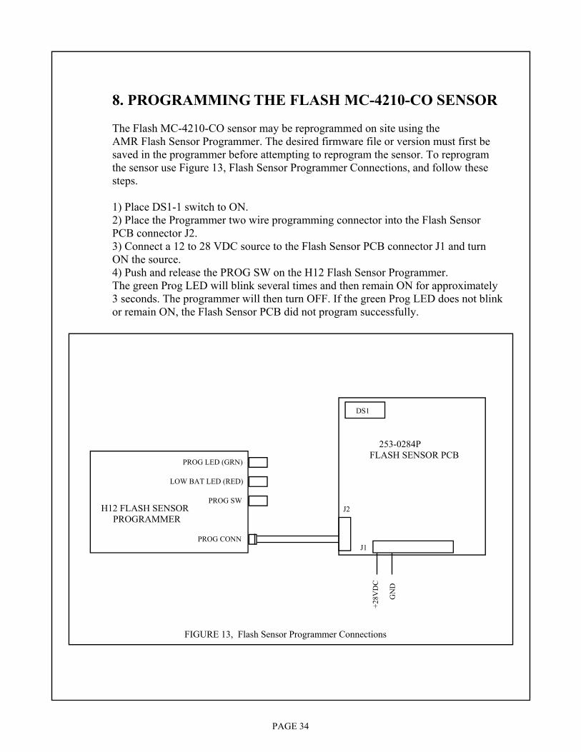
8. PROGRAMMING THE FLASH MC-4210-CO SENSOR The Flash MC-4210-CO sensor may be reprogrammed on site using the AMR Flash Sensor Programmer. The desired firmware file or version must first be saved in the programmer before attempting to reprogram the sensor. To reprogram the sensor use Figure 13, Flash Sensor Programmer Connections, and follow these steps. 1) Place DS1-1 switch to ON. 2) Place the Programmer two wire programming connector into the Flash Sensor PCB connector J2. 3) Connect a 12 to 28 VDC source to the Flash Sensor PCB connector J1 and turn ON the source. 4) Push and release the PROG SW on the H12 Flash Sensor Programmer. The green Prog LED will blink several times and then remain ON for approximately 3 seconds. The programmer will then turn OFF. If the green Prog LED does not blink or remain ON, the Flash Sensor PCB did not program successfully.
H12 FLASH SENSOR PROGRAMMER
PROG CONN
PROG SW
PROG LED (GRN)
LOW BAT LED (RED)
253-0284P FLASH SENSOR PCB
DS1
J2
J1
+28V
DC
GN
D
FIGURE 13, Flash Sensor Programmer Connections
PAGE 35
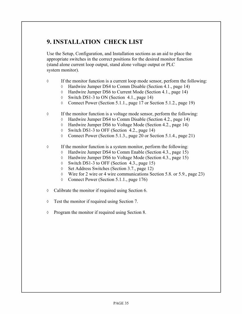
9. INSTALLATION CHECK LIST Use the Setup, Configuration, and Installation sections as an aid to place the appropriate switches in the correct positions for the desired monitor function (stand alone current loop output, stand alone voltage output or PLC system monitor).
◊ If the monitor function is a current loop mode sensor, perform the following: ◊ Hardwire Jumper DS4 to Comm Disable (Section 4.1., page 14) ◊ Hardwire Jumper DS6 to Current Mode (Section 4.1., page 14) ◊ Switch DS1-3 to ON (Section 4.1., page 14) ◊ Connect Power (Section 5.1.1., page 17 or Section 5.1.2., page 19)
◊ If the monitor function is a voltage mode sensor, perform the following:
◊ Hardwire Jumper DS4 to Comm Disable (Section 4.2., page 14) ◊ Hardwire Jumper DS6 to Voltage Mode (Section 4.2., page 14) ◊ Switch DS1-3 to OFF (Section 4.2., page 14) ◊ Connect Power (Section 5.1.3., page 20 or Section 5.1.4., page 21)
◊ If the monitor function is a system monitor, perform the following:
◊ Hardwire Jumper DS4 to Comm Enable (Section 4.3., page 15) ◊ Hardwire Jumper DS6 to Voltage Mode (Section 4.3., page 15) ◊ Switch DS1-3 to OFF (Section 4.3., page 15) ◊ Set Address Switches (Section 3.7., page 12) ◊ Wire for 2 wire or 4 wire communications Section 5.8. or 5.9., page 23) ◊ Connect Power (Section 5.1.1., page 176)
◊ Calibrate the monitor if required using Section 6. ◊ Test the monitor if required using Section 7.
◊ Program the monitor if required using Section 8.
PAGE 36
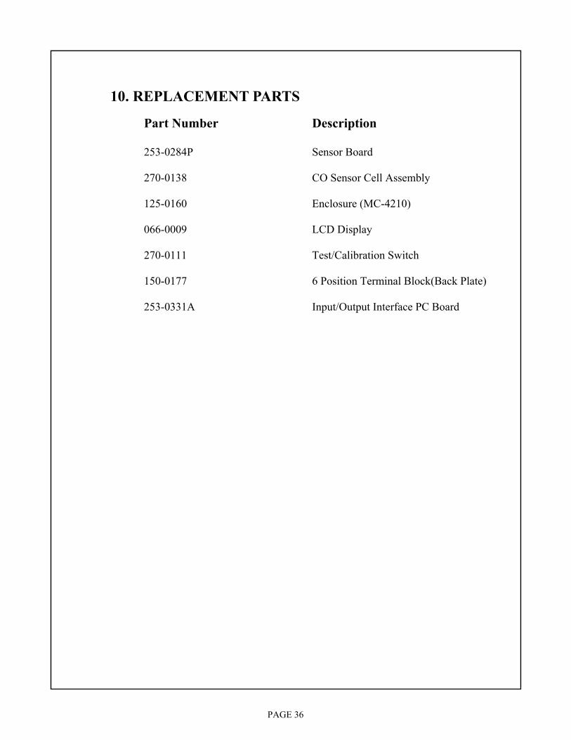
10. REPLACEMENT PARTS Part Number Description 253-0284P Sensor Board 270-0138 CO Sensor Cell Assembly 125-0160 Enclosure (MC-4210) 066-0009 LCD Display 270-0111 Test/Calibration Switch 150-0177 6 Position Terminal Block(Back Plate) 253-0331A Input/Output Interface PC Board