Embed Size (px)
Citation preview
TSG – Making Every Drop Count Page 1
Membrane Bioreactors
Prepared By:
Kiera S. Fitzgerald, P.E. TSG Technologies, Inc.
2401 NE 18th Terr. Suite B Gainesville, Fl 32609
(352) 371-6925 x 305
June 2008
Proprietary Notice
TSG Technologies, Inc. considers the data and information contained in this document to be proprietary. This document and any information contained herein shall not be disclosed outside the client and shall not be duplicated, used, or disclosed in whole or in part for any purpose other than evaluating the proposed development’s wastewater needs.
2008
Copyright 2008©TSG
TSG – Making Every Drop Count Page 2
The following paper provides some general information based on TSG Technologies, Inc.’s experience with Membrane Bioreactors (MBRs). It focuses on two types of MBRs: Kubota’s plate membrane and Zenon’s hollow fiber membranes. These are two membrane manufacturers that have a significant number of systems in operation and are systems that we are currently using in our small plant designs. It is not the intent of this paper to suggest that our clients exclude other manufacturers from participating in their projects. Rather, it is our intent to provide a synopsis of our experiences with these two systems, provide some explanation of the advantages of using MBRs and to explain some of the differences in the construction and operation of these two systems. After reading this synopsis, it is our hope that you will better understand membrane bioreactors and will allow TSG Technologies, Inc. the privilege of working with you on your next wastewater treatment plant, be it an MBR or a more conventional technology.
Membrane Bioreactors Membrane Bioreactors combine conventional biological treatment processes with membrane filtration to provide an advanced level of organic and suspended solids removal. When designed accordingly, these systems can also provide an advanced level of nutrient removal. In an MBR system, the membranes are submerged in an aerated biological reactor. The membranes have porosities ranging from 0.035 microns to 0.4 microns (depending on the manufacturer), which is considered between micro and ultra filtration. This level of filtration allows high quality effluent to be drawn through the membranes and eliminates the sedimentation and filtration processes typically used for wastewater treatment. Because the need for sedimentation is eliminated, the biological process can operate at a much higher mixed liquor concentration. This dramatically reduces the process tankage required and allows many existing plants to be upgraded without adding new tanks. To provide optimal aeration and scour around the membranes, the mixed liquor is typically kept in the 1.0-1.2% solids range, which is 4 times that of a conventional plant. The membrane bioreactor has several distinct advantages over the Extended Aeration (EA) and Sequencing Batch Reactor (SBR) systems that make most regulatory agencies look favorably on MBRs, especially for small plants in environmentally sensitive areas. However, since the equipment is more costly than conventional plants, it is not the appropriate technology for every application. The key advantages of MBRs are that they provide a higher level of treatment and are much more resistant to upsets due to fluctuating influent flows. In addition, if land is at a premium, the MBR system can be designed to have a much smaller footprint. Some of the other benefits of MBRs include: Hydraulic Retention Time (HRT) of 4-8 hours vs 16-24 hours Solids Retention Time (SRT) of 15-365 days, can vary based on flow without negative process
impact MLSS of 10-15,000 mg/L Sludge Yield of 20-40% less than conventional Footprint of 25% Conventional Plant Modular expandability Highest quality effluent Capable of meeting AWT standards for nutrient removal Barrier to Giardia/Crypto Less susceptible to upsets due to flow variations Less odor Simple, yet sophisticated
To better explain the process, a schematic of a membrane system is provided below.

TSG – Making Every Drop Count Page 3
SIMPLIFIED MBR SCHEMATIC
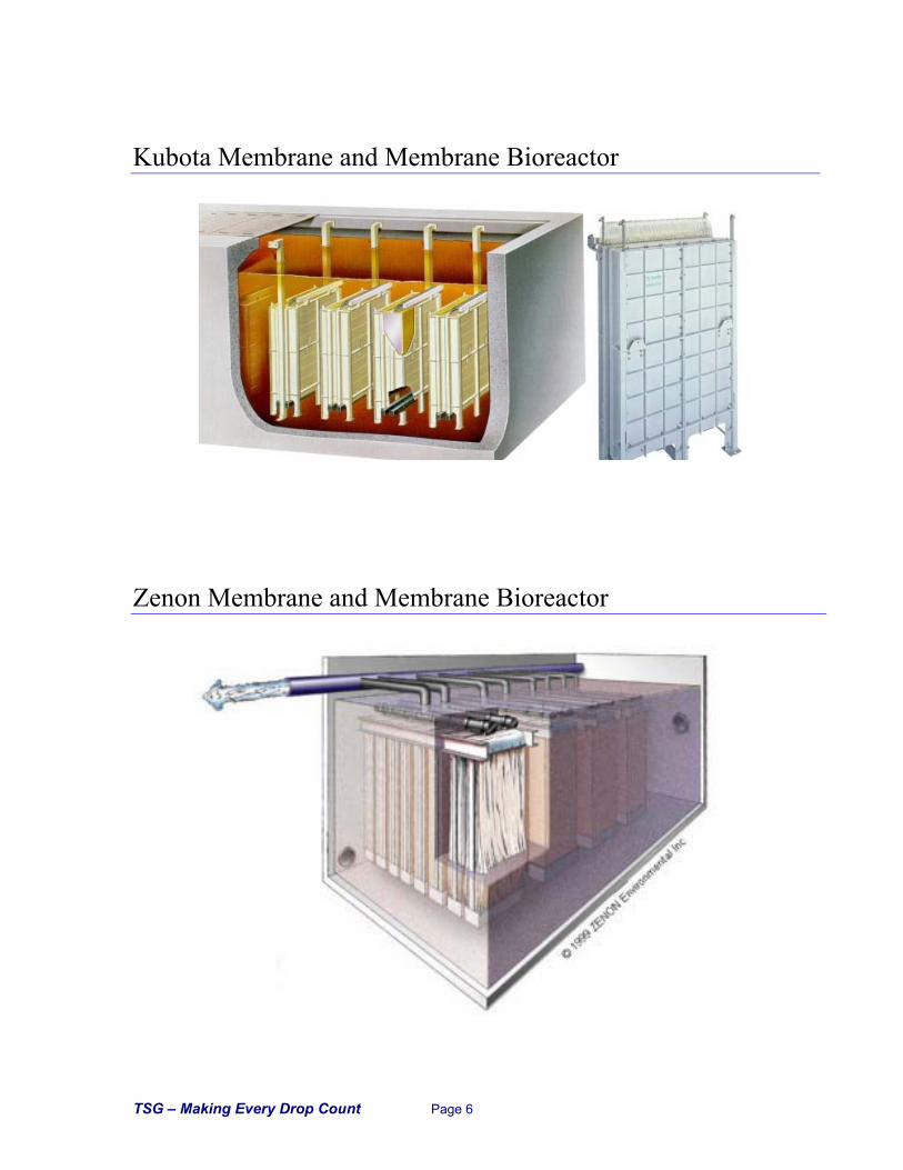
As noted, the membrane manufacturers that we are currently working with are Zenon and Kubota. Process-wise, these two systems are very similar and both will provide high quality effluent. However, there are several differences in how the membranes themselves are configured and, in turn, how the ancillary equipment (pumps, cleaning systems, valves) is configured to support each type of membrane. Kubota is a plate membrane where the Zenon’s ZeeWeed® is a hollow fiber membrane. The Kubota plate membrane is a slightly looser membrane. ZeeWeed®’s pore size is 0.1 micron (0.035 micron effective); Kubota’s is 0.4 micron (0.1 micron effective). As such, in theory, Kubota’s removal efficiency will not be as good as the Zenon hollow fiber system. However, it has proven it can meet all USEPA standards for public access reuse, it is has an order of magnitude better removal than a conventional sand or fabric filter and it will provide bacterial level removal. (As illustrated in the attached Filtration Spectrum graphic.)
ZeeWeed® Hollow Fiber Membrane
Kubota Flat Plate Membrane
Treated
WaterWaste Sludge to Disposal
Air ScourBlower
Raw Wastewater
Influent Screen
Membrane Module
Mixed Liquor Recirculation
Pump
Bioreactor Process Aeration Blower
Permeate Pump
Anoxic Zone
ML Recycle
TSG – Making Every Drop Count Page 4
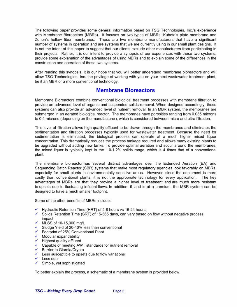
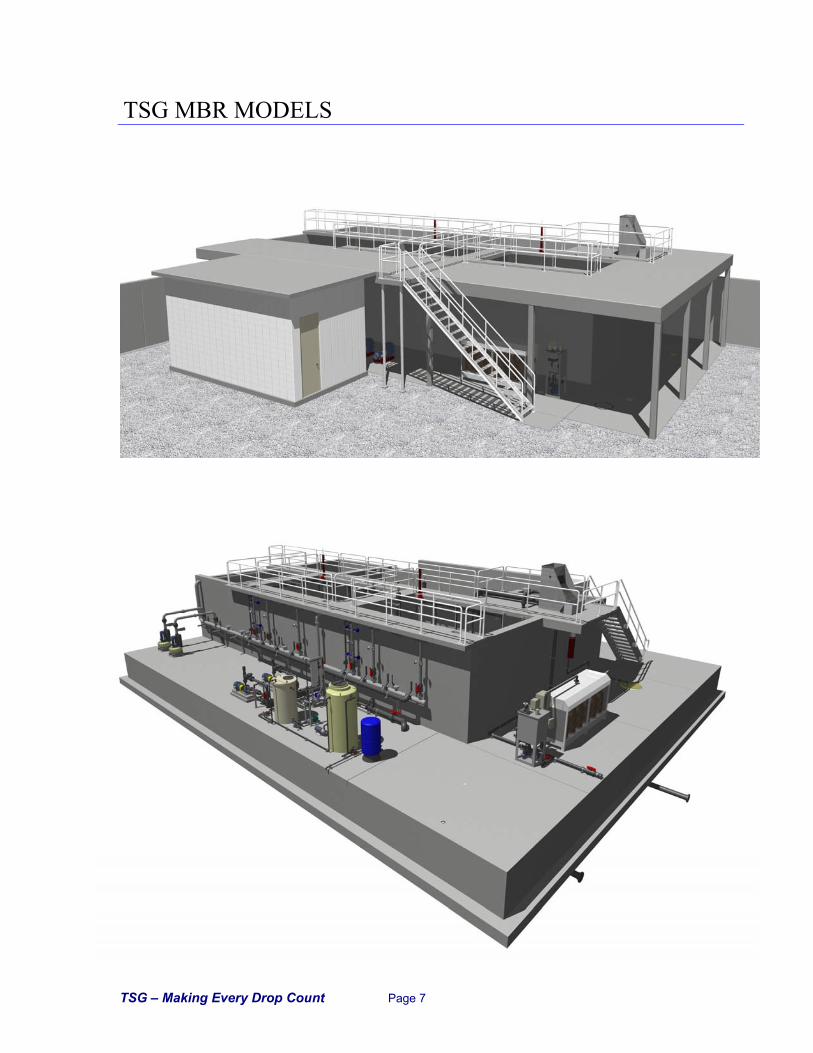
In addition, as a hollow fiber, the Zenon system can operate at a higher suction pressure than the Kubota plate system. This differential does allow operators to “push” the Zenon system harder than the Kubota system when it is fouled. However, the looser Kubota membrane does allow a higher “flux rate”, or gallons per day per square foot of membrane. Though the tighter porosity of the Zenon membrane results in higher rates of particle rejection, it creates a more complex plant since Zenon requires an automatic backpulse system and Kubota does not. The Zenon backpulse system is used to force flow back through the fibers every 10-15 minutes to prevent plugging. This system is integrated into the permeate pump skid and requires up to 10 automatic valves. Since the Kubota system does not use a back pulse system, the mechanics are much simpler. The process schematics provided below illustrate the differences between the permeate valving for these two systems.
ZENON ZEEWEED® SCHEMATIC
KUBOTA SCHEMATIC
Treated Water Clean
in Place Tank
Waste Sludge to Disposal
Air ScourBlower
Raw Wastewater
Influent Screen
Membrane Module
Mixed Liquor Recirculation
Pump
Bioreactor AerationBlower
Permeate Pumps
Backpulse Pump
Anoxic Zone
Chlorine Feed Tank
ML Recycle
Treated
Water
Chlorine Feed Tank
Waste Sludge to Disposal
Air ScourBlower
Raw Wastewater
Influent Screen
Membrane Module
Mixed Liquor Recirculation
Pump
Bioreactor AerationBlower
Permeate Pump
Anoxic Zone
ML Recycle
TSG – Making Every Drop Count Page 5
Another key difference is how the membranes are cleaned. Both systems occasionally require an intense cleaning to remove excessive biogrowth and grease that can foul the membranes. The frequency of cleaning is a site-specific factor but for most plants, cleaning is required every three to six months. For this type of cleaning, the membranes soak in a dilute solution of sodium hypochlorite for a period of time before being returned to service. In certain cases, a mild acid or caustic solution may also be required. For the Zenon system design, individual membrane chambers are provided to allow in situ cleaning of the membrane banks. Zenon membranes are taken out of service, the chambers drained and the membranes are soaked for 24-48 hours in 200 to 1000 mg/L of bleach. Once clean, the chlorine remaining in the chamber can be readily deactivated by the addition of a dechlorination chemical such as dry sodium sulfite. Unlike the Zenon system, the Kubota cleaning cycle can be done in the mixed liquor WITHOUT draining the tank. A dilute solution of bleach is allowed to flow by gravity back through the permeate lines. The solution soaks in the membranes for 1-2 hours, and then the plant is brought back on-line. Only a negligible fraction of the total biomass (i.e. that which is growing on each membrane plate) is killed off during this process due to the minimal amount of 0.5% to 1.0% bleach solution used. As a result, you still have an active biomass in the MBR upon startup after cleaning, resulting in a simplified cleaning process that minimizes downtime. If effluent requirements dictate, the “first flush” of the effluent after cleaning can be recycled to the head of the plant to minimize particulate release. However, very few plants will have this stringent an effluent requirement. In addition to cleaning the membranes themselves, rags and stringy material can catch on the membranes fibers and casing and interfere with proper air scour. The Zenon membrane fibers are in cassettes and the entire cassette must be lifted out of the tank. Our experience is that this de-ragging is needed at least as frequently as the chlorine cleaning and therefore recommend installing a hoist and monorail or bridge crane with the Zenon systems. Kubota has 50 to 400 membrane plates in each cassette and, if desired, the entire case can be lifted for maintenance. However, since individual plates can be pulled up by hand and de-ragged, the need for a permanent hoist is eliminated for smaller facilities. When comparing MBRs to other processes, the issue of energy efficiency is often brought up. MBRs utilize aeration for membrane scour and require permeate pumping systems. At full design flow, MBRs typically use more power. However, few plants operate at full design flow, especially those in seasonal resorts. By properly designing the MBRs, portions of an MBR plant can be taken out of service and the cassettes can be cycled during low flow periods to provide a lower net energy cost. In addition, because they do not need separate cleaning chambers, and because they are provided with a “box” to control the air scour, the Kubota flat plate membranes can be arranged in the final aeration chamber and the scour aeration can also provide process aeration. This can virtually eliminate the extra power due to scour aeration for this style of MBR. In summary, TSG has designed numerous MBR systems including 7 systems we have built and/or operated in the Caribbean. When considering whether to use this technology or not, the above listed advantages need to be weighed against the potential additional capital cost.
TSG – Making Every Drop Count Page 6
Kubota Membrane and Membrane Bioreactor
Zenon Membrane and Membrane Bioreactor
TSG – Making Every Drop Count Page 7
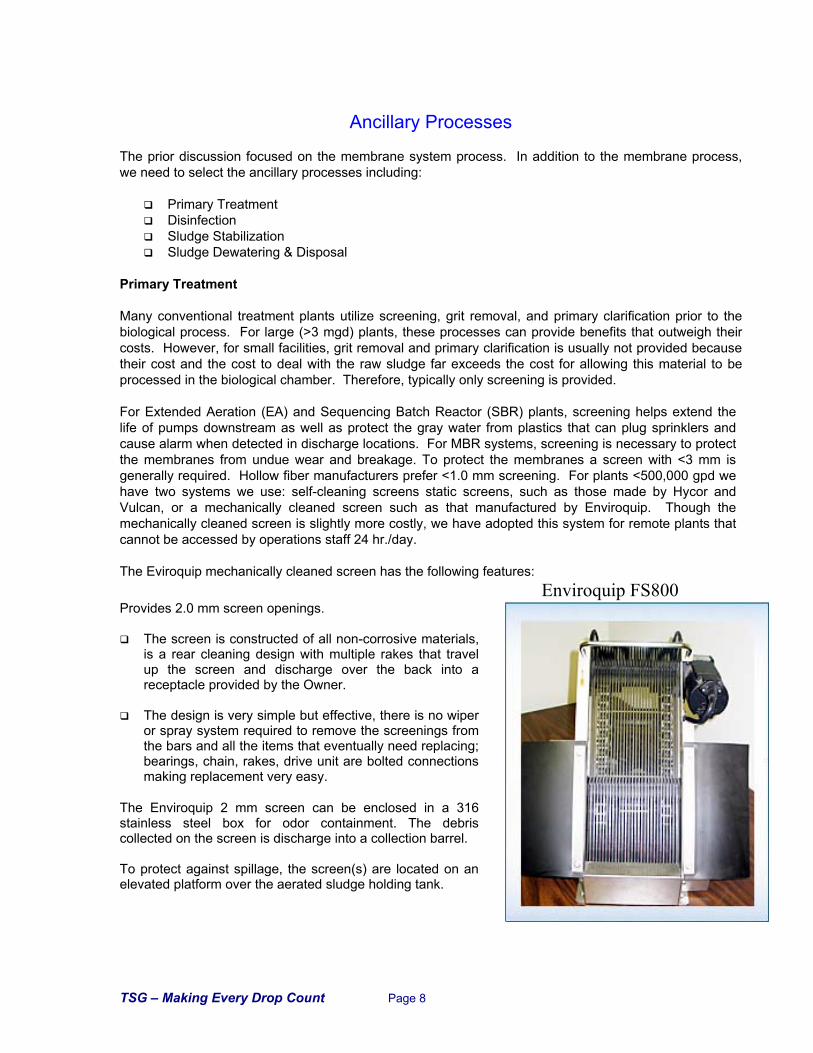
TSG MBR MODELS
TSG – Making Every Drop Count Page 8
Ancillary Processes
The prior discussion focused on the membrane system process. In addition to the membrane process, we need to select the ancillary processes including:
Primary Treatment Disinfection Sludge Stabilization Sludge Dewatering & Disposal
Primary Treatment Many conventional treatment plants utilize screening, grit removal, and primary clarification prior to the biological process. For large (>3 mgd) plants, these processes can provide benefits that outweigh their costs. However, for small facilities, grit removal and primary clarification is usually not provided because their cost and the cost to deal with the raw sludge far exceeds the cost for allowing this material to be processed in the biological chamber. Therefore, typically only screening is provided. For Extended Aeration (EA) and Sequencing Batch Reactor (SBR) plants, screening helps extend the life of pumps downstream as well as protect the gray water from plastics that can plug sprinklers and cause alarm when detected in discharge locations. For MBR systems, screening is necessary to protect the membranes from undue wear and breakage. To protect the membranes a screen with <3 mm is generally required. Hollow fiber manufacturers prefer <1.0 mm screening. For plants <500,000 gpd we have two systems we use: self-cleaning screens static screens, such as those made by Hycor and Vulcan, or a mechanically cleaned screen such as that manufactured by Enviroquip. Though the mechanically cleaned screen is slightly more costly, we have adopted this system for remote plants that cannot be accessed by operations staff 24 hr./day. The Eviroquip mechanically cleaned screen has the following features:
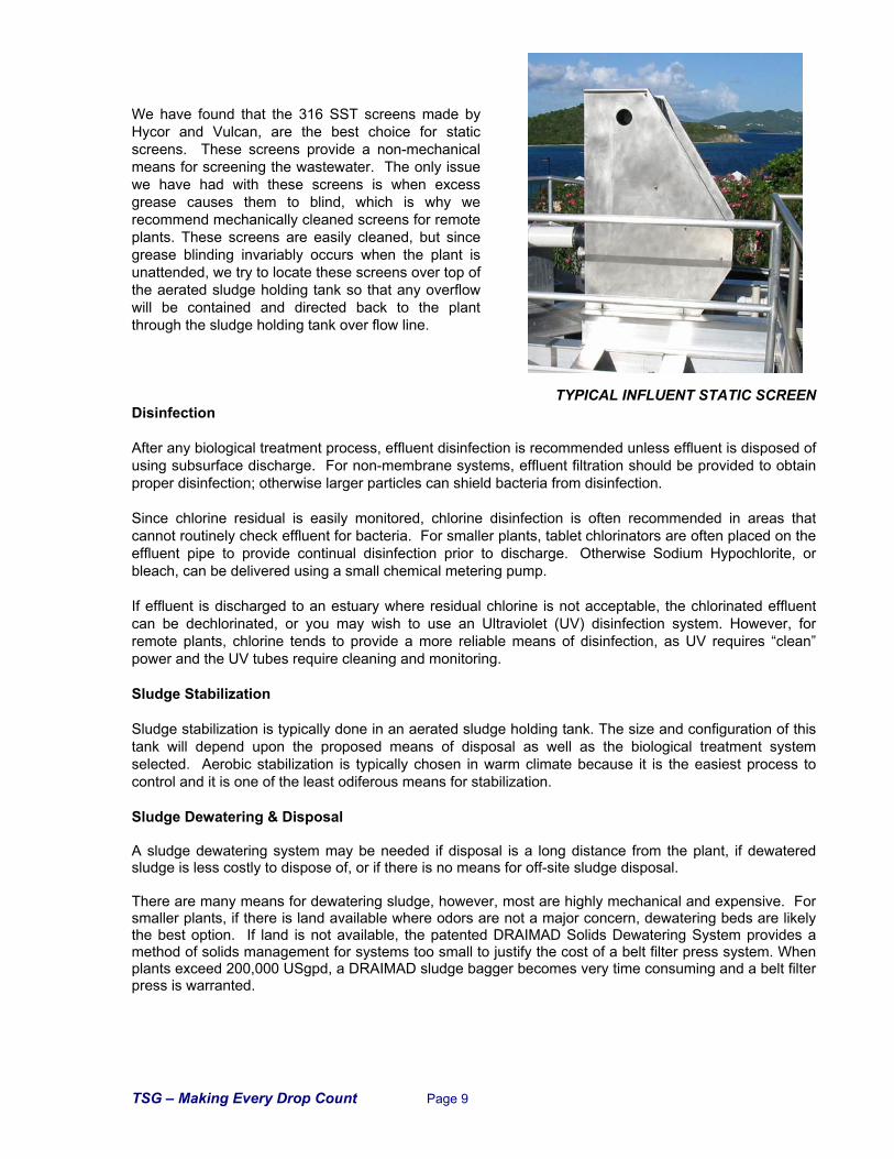
Enviroquip FS800 Provides 2.0 mm screen openings.
The screen is constructed of all non-corrosive materials, is a rear cleaning design with multiple rakes that travel up the screen and discharge over the back into a receptacle provided by the Owner.
The design is very simple but effective, there is no wiper
or spray system required to remove the screenings from the bars and all the items that eventually need replacing; bearings, chain, rakes, drive unit are bolted connections making replacement very easy.
The Enviroquip 2 mm screen can be enclosed in a 316 stainless steel box for odor containment. The debris collected on the screen is discharge into a collection barrel. To protect against spillage, the screen(s) are located on an elevated platform over the aerated sludge holding tank.
TSG – Making Every Drop Count Page 9
We have found that the 316 SST screens made by Hycor and Vulcan, are the best choice for static screens. These screens provide a non-mechanical means for screening the wastewater. The only issue we have had with these screens is when excess grease causes them to blind, which is why we recommend mechanically cleaned screens for remote plants. These screens are easily cleaned, but since grease blinding invariably occurs when the plant is unattended, we try to locate these screens over top of the aerated sludge holding tank so that any overflow will be contained and directed back to the plant through the sludge holding tank over flow line.
TYPICAL INFLUENT STATIC SCREEN Disinfection After any biological treatment process, effluent disinfection is recommended unless effluent is disposed of using subsurface discharge. For non-membrane systems, effluent filtration should be provided to obtain proper disinfection; otherwise larger particles can shield bacteria from disinfection. Since chlorine residual is easily monitored, chlorine disinfection is often recommended in areas that cannot routinely check effluent for bacteria. For smaller plants, tablet chlorinators are often placed on the effluent pipe to provide continual disinfection prior to discharge. Otherwise Sodium Hypochlorite, or bleach, can be delivered using a small chemical metering pump. If effluent is discharged to an estuary where residual chlorine is not acceptable, the chlorinated effluent can be dechlorinated, or you may wish to use an Ultraviolet (UV) disinfection system. However, for remote plants, chlorine tends to provide a more reliable means of disinfection, as UV requires “clean” power and the UV tubes require cleaning and monitoring. Sludge Stabilization Sludge stabilization is typically done in an aerated sludge holding tank. The size and configuration of this tank will depend upon the proposed means of disposal as well as the biological treatment system selected. Aerobic stabilization is typically chosen in warm climate because it is the easiest process to control and it is one of the least odiferous means for stabilization. Sludge Dewatering & Disposal A sludge dewatering system may be needed if disposal is a long distance from the plant, if dewatered sludge is less costly to dispose of, or if there is no means for off-site sludge disposal. There are many means for dewatering sludge, however, most are highly mechanical and expensive. For smaller plants, if there is land available where odors are not a major concern, dewatering beds are likely the best option. If land is not available, the patented DRAIMAD Solids Dewatering System provides a method of solids management for systems too small to justify the cost of a belt filter press system. When plants exceed 200,000 USgpd, a DRAIMAD sludge bagger becomes very time consuming and a belt filter press is warranted.
TSG – Making Every Drop Count Page 10
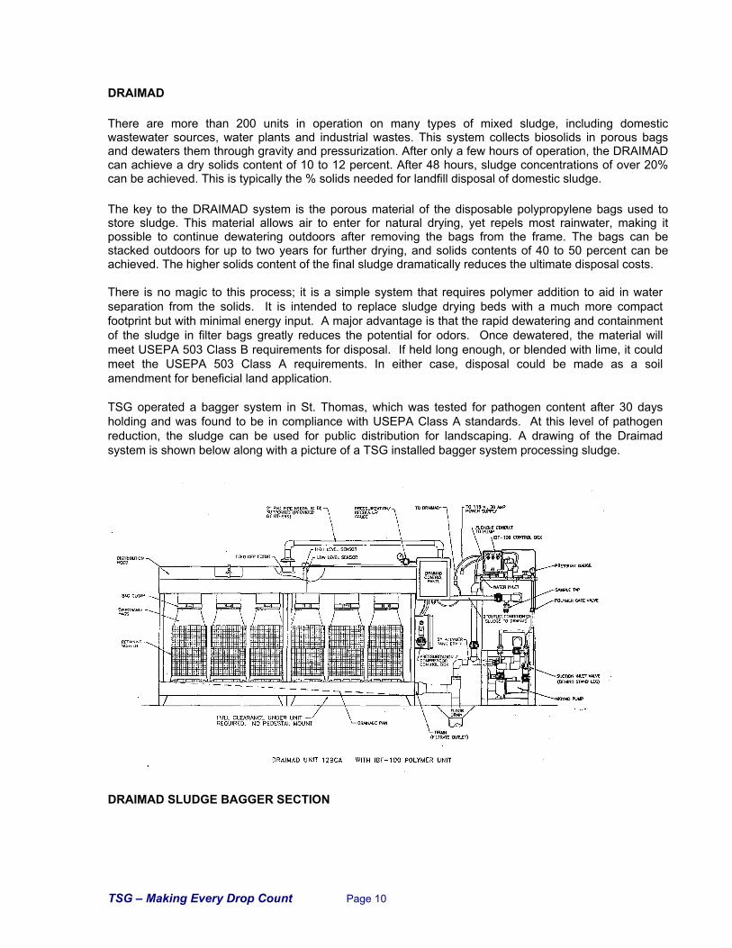
DRAIMAD
There are more than 200 units in operation on many types of mixed sludge, including domestic wastewater sources, water plants and industrial wastes. This system collects biosolids in porous bags and dewaters them through gravity and pressurization. After only a few hours of operation, the DRAIMAD can achieve a dry solids content of 10 to 12 percent. After 48 hours, sludge concentrations of over 20% can be achieved. This is typically the % solids needed for landfill disposal of domestic sludge.
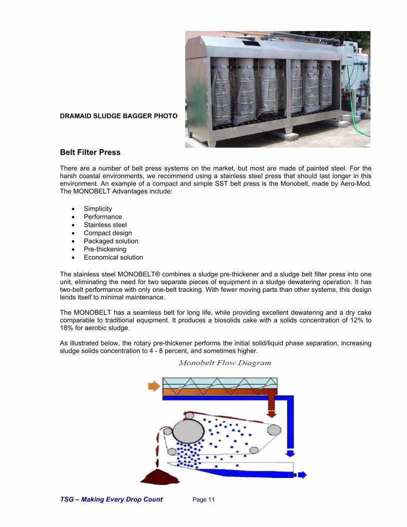
The key to the DRAIMAD system is the porous material of the disposable polypropylene bags used to store sludge. This material allows air to enter for natural drying, yet repels most rainwater, making it possible to continue dewatering outdoors after removing the bags from the frame. The bags can be stacked outdoors for up to two years for further drying, and solids contents of 40 to 50 percent can be achieved. The higher solids content of the final sludge dramatically reduces the ultimate disposal costs. There is no magic to this process; it is a simple system that requires polymer addition to aid in water separation from the solids. It is intended to replace sludge drying beds with a much more compact footprint but with minimal energy input. A major advantage is that the rapid dewatering and containment of the sludge in filter bags greatly reduces the potential for odors. Once dewatered, the material will meet USEPA 503 Class B requirements for disposal. If held long enough, or blended with lime, it could meet the USEPA 503 Class A requirements. In either case, disposal could be made as a soil amendment for beneficial land application. TSG operated a bagger system in St. Thomas, which was tested for pathogen content after 30 days holding and was found to be in compliance with USEPA Class A standards. At this level of pathogen reduction, the sludge can be used for public distribution for landscaping. A drawing of the Draimad system is shown below along with a picture of a TSG installed bagger system processing sludge. DRAIMAD SLUDGE BAGGER SECTION
TSG – Making Every Drop Count Page 11
DRAMAID SLUDGE BAGGER PHOTO
Belt Filter Press There are a number of belt press systems on the market, but most are made of painted steel. For the harsh coastal environments, we recommend using a stainless steel press that should last longer in this environment. An example of a compact and simple SST belt press is the Monobelt, made by Aero-Mod. The MONOBELT Advantages include:
• Simplicity • Performance • Stainless steel • Compact design • Packaged solution • Pre-thickening • Economical solution
The stainless steel MONOBELT® combines a sludge pre-thickener and a sludge belt filter press into one unit, eliminating the need for two separate pieces of equipment in a sludge dewatering operation. It has two-belt performance with only one-belt tracking. With fewer moving parts than other systems, this design lends itself to minimal maintenance. The MONOBELT has a seamless belt for long life, while providing excellent dewatering and a dry cake comparable to traditional equipment. It produces a biosolids cake with a solids concentration of 12% to 18% for aerobic sludge. As illustrated below, the rotary pre-thickener performs the initial solid/liquid phase separation, increasing sludge solids concentration to 4 - 8 percent, and sometimes higher.
TSG – Making Every Drop Count Page 12
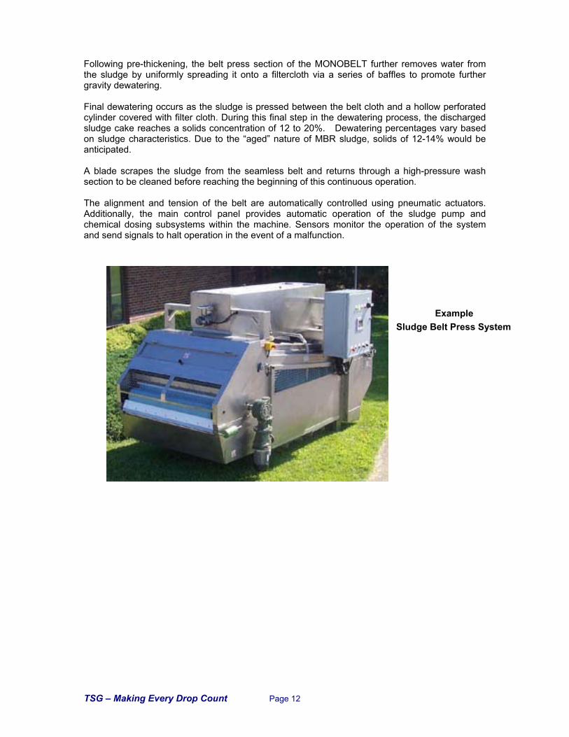
Following pre-thickening, the belt press section of the MONOBELT further removes water from the sludge by uniformly spreading it onto a filtercloth via a series of baffles to promote further gravity dewatering. Final dewatering occurs as the sludge is pressed between the belt cloth and a hollow perforated cylinder covered with filter cloth. During this final step in the dewatering process, the discharged sludge cake reaches a solids concentration of 12 to 20%. Dewatering percentages vary based on sludge characteristics. Due to the “aged” nature of MBR sludge, solids of 12-14% would be anticipated. A blade scrapes the sludge from the seamless belt and returns through a high-pressure wash section to be cleaned before reaching the beginning of this continuous operation. The alignment and tension of the belt are automatically controlled using pneumatic actuators. Additionally, the main control panel provides automatic operation of the sludge pump and chemical dosing subsystems within the machine. Sensors monitor the operation of the system and send signals to halt operation in the event of a malfunction.
Example Sludge Belt Press System
TSG – Making Every Drop Count Page 13
The Filtration Spectrum
ZeeW
eed
Ku
bota
Con
ven
tion
al F
iltra
tion
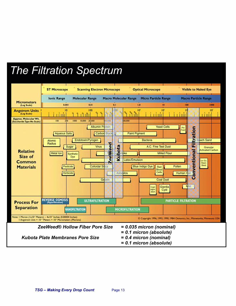
ZeeWeed® Hollow Fiber Pore Size = 0.035 micron (nominal) = 0.1 micron (absolute)
Kubota Plate Membranes Pore Size = 0.4 micron (nominal) = 0.1 micron (absolute)