Embed Size (px)
Citation preview

MBA Health and Safety Conference - PE15 March 2018
Considerations essential to safe temporary works design and execution on site.
Dévan Venter
Lead Engineer – PERI KZN Region
■ Introduction.
■ Engineering considerations.
■ Codes, good practices and safety.
■ Typical considerations for shoring.
■ Typical errors and what to look out for on site.
■ Typical considerations for walls / columns.
■ Typical considerations for scaffolding.
■ Bracing 101.
DV2

Engineering considerations
Unstable founding conditions
Mobile / movable
Removable after casting concrete
Dynamic / impact loading
Labour intensive construction opposed to mechanized (South Africa).
Instability condition before concrete is cast.
DV
3
Codes, good practices and safety
BS 5975.
DIN EN 12810 / 12811 / 12812.
SANS10085-1 (Scaffolding) and Unit Standard 243035.
Special structural steel and timber SANS 10162 and SABS 0163.
Wind = SANS 10160-3.
DV
4
Type verification
Codes, good practices and safety
Is only valid for a predefined application area.
Has to be described through a valid assembly instruction.
Proof engineer needs to check, if the type test is valid for that system.
Proof in structual analysis
Applied stress ≤ Permissible stress
When using a structural analysis, type verifications
have to be proofed from scratch every time.
DV
5
Type test
Codes, good practices and safety
Test report from an authority (e.g. state / federal testing office) is available.
Is a service offer.
Avoids a type varification from being
checked for every project individually.
DV
6
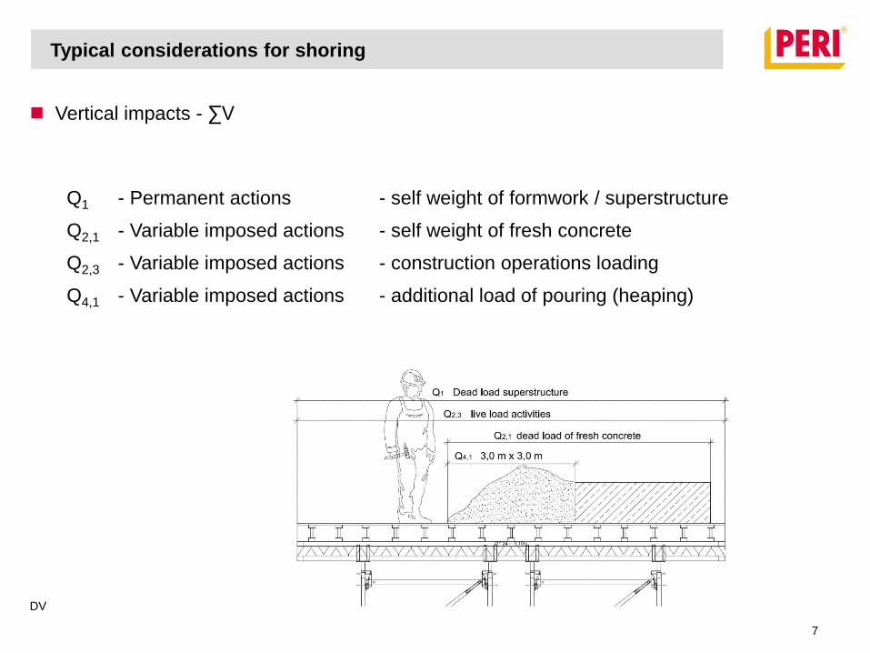
Vertical impacts - ∑V
Typical considerations for shoring
Q1 - Permanent actions - self weight of formwork / superstructure
Q2,1 - Variable imposed actions - self weight of fresh concrete
Q2,3 - Variable imposed actions - construction operations loading
Q4,1 - Variable imposed actions - additional load of pouring (heaping)
DV
7
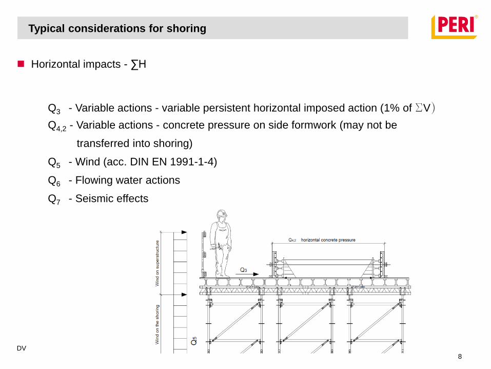
Horizontal impacts - ∑H
Typical considerations for shoring
Q3 - Variable actions - variable persistent horizontal imposed action (1% of SV)
Q4,2 - Variable actions - concrete pressure on side formwork (may not be
transferred into shoring)
Q5 - Wind (acc. DIN EN 1991-1-4)
Q6 - Flowing water actions
Q7 - Seismic effects
DV
8
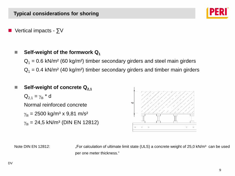
Vertical impacts - ∑V
Self-weight of the formwork Q1
Q1 = 0.6 kN/m² (60 kg/m²) timber secondary girders and steel main girders
Q1 = 0.4 kN/m² (40 kg/m²) timber secondary girders and timber main girders
Self-weight of concrete Q2,1
Q2,1 = gB * d
Normal reinforced concrete
gB = 2500 kg/m³ x 9,81 m/s²
gB = 24,5 kN/m³ (DIN EN 12812)
Note DIN EN 12812: „For calculation of ultimate limit state (ULS) a concrete weight of 25,0 kN/m³ can be used
per one meter thickness.“
Typical considerations for shoring
DV
9
Horizontal impacts - ∑H
Typical considerations for shoring
Wind:
Maximum wind = 0.5kPa up to 8.4m, 0.8kPa over 8.4m or according to
SANS10160-3.
Working wind = 0.2kPa (DIN EN)
DV
10
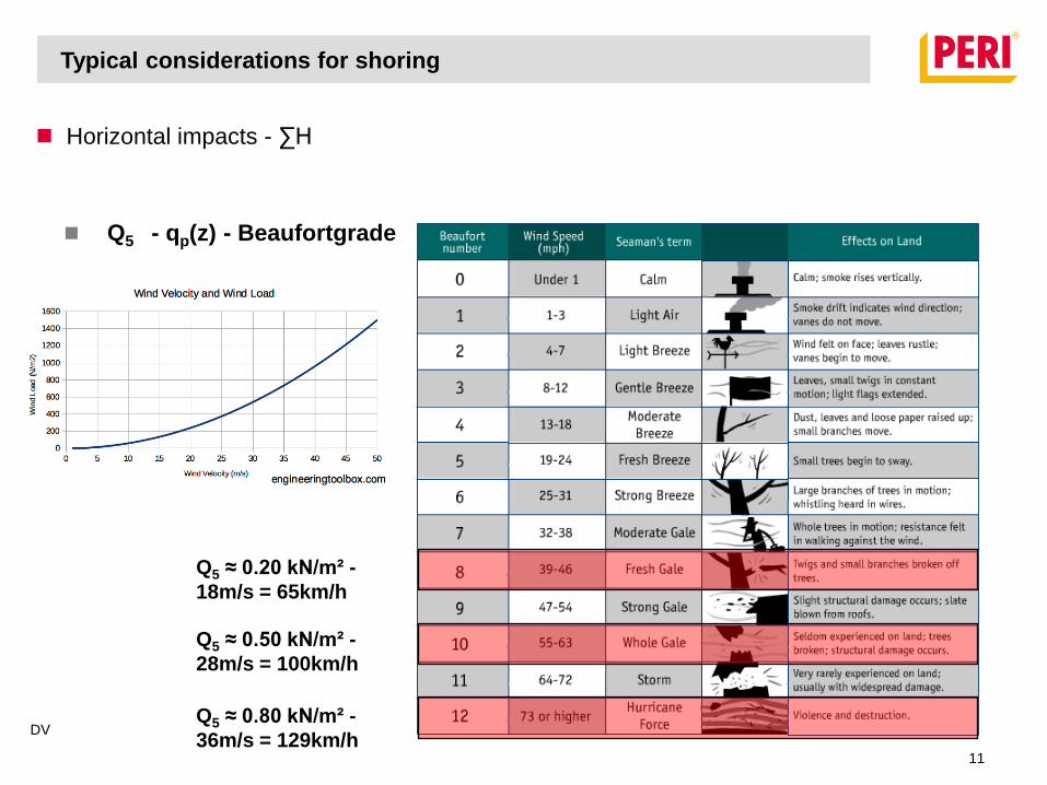
Horizontal impacts - ∑H
Q5 - qp(z) - Beaufortgrade
Typical considerations for shoring
Q5 ≈ 0.20 kN/m² -
18m/s = 65km/h
Q5 ≈ 0.50 kN/m² -
28m/s = 100km/h
Q5 ≈ 0.80 kN/m² -
36m/s = 129km/hDV
11
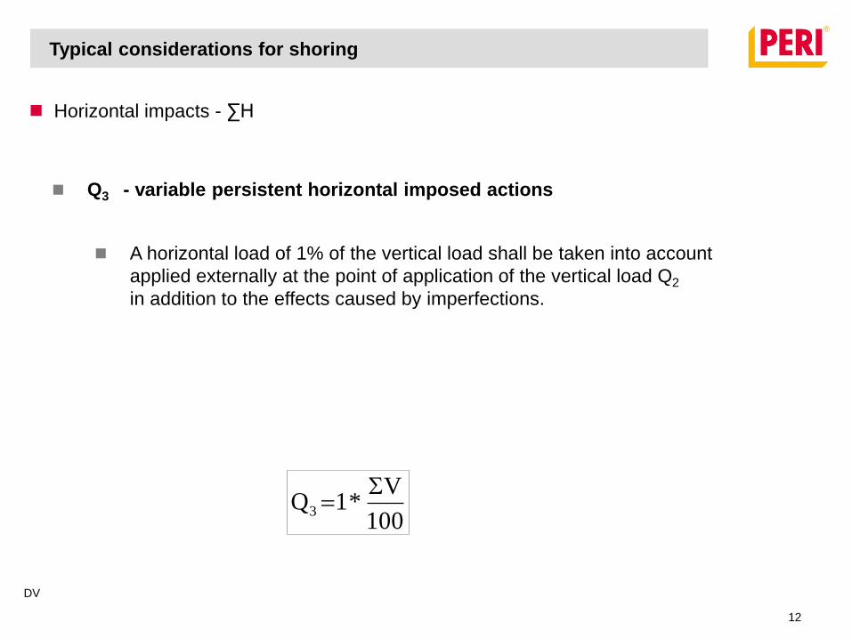
Horizontal impacts - ∑H
Q3 - variable persistent horizontal imposed actions
A horizontal load of 1% of the vertical load shall be taken into account
applied externally at the point of application of the vertical load Q2
in addition to the effects caused by imperfections.
100
V*1Q3
Typical considerations for shoring
DV
12
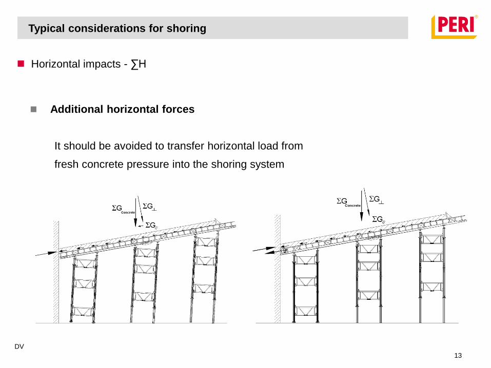
Horizontal impacts - ∑H
Additional horizontal forces
It should be avoided to transfer horizontal load from
fresh concrete pressure into the shoring system
Typical considerations for shoring
DV
13
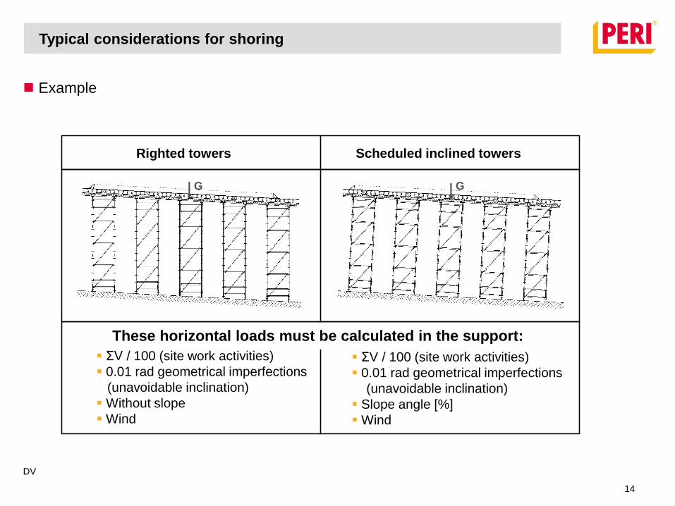
Example
Typical considerations for shoring
These horizontal loads must be calculated in the support:
ƩV / 100 (site work activities)
0.01 rad geometrical imperfections
(unavoidable inclination)
Without slope
Wind
GG
Scheduled inclined towersRighted towers
ƩV / 100 (site work activities)
0.01 rad geometrical imperfections
(unavoidable inclination)
Slope angle [%]
Wind
DV
14
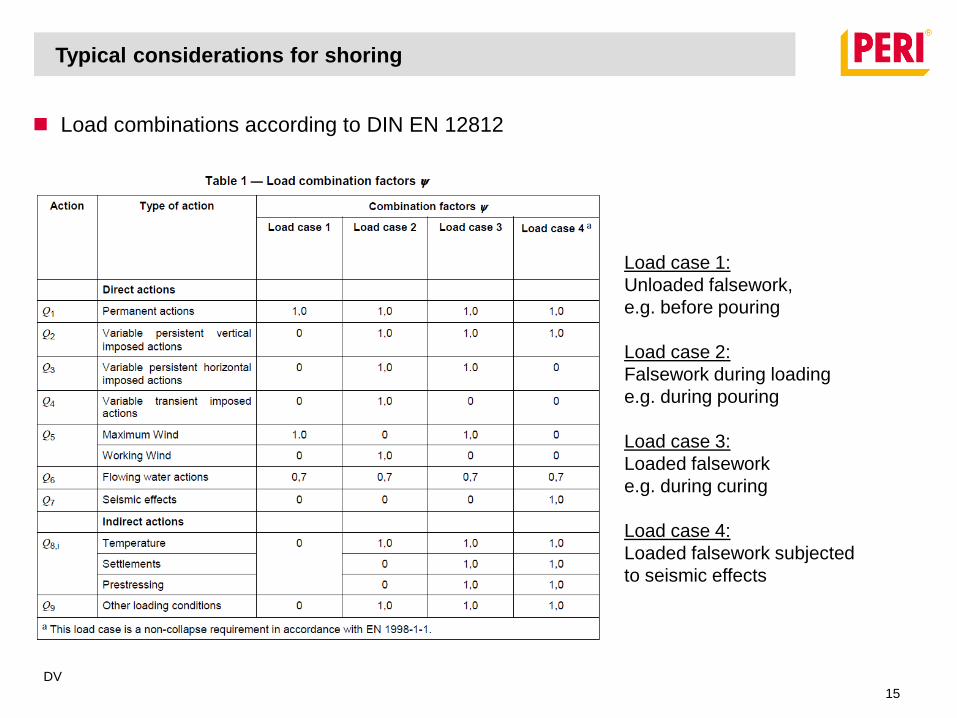
Load combinations according to DIN EN 12812
Load case 1:
Unloaded falsework,
e.g. before pouring
Load case 2:
Falsework during loading
e.g. during pouring
Load case 3:
Loaded falsework
e.g. during curing
Load case 4:
Loaded falsework subjected
to seismic effects
Typical considerations for shoring
DV
15
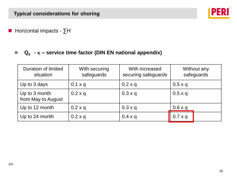
Horizontal impacts - ∑H
Q5 - k – service time factor (DIN EN national appendix)
Typical considerations for shoring
Duration of limited
situation
With securing
safeguards
With increased
securing safeguards
Without any
safeguards
Up to 3 days 0.1 x q 0.2 x q 0.5 x q
Up to 3 month
from May to August
0.2 x q 0.3 x q 0.5 x q
Up to 12 month 0.2 x q 0.3 x q 0.6 x q
Up to 24 month 0.2 x q 0.4 x q 0.7 x q
DV
16
Typical considerations for shoring
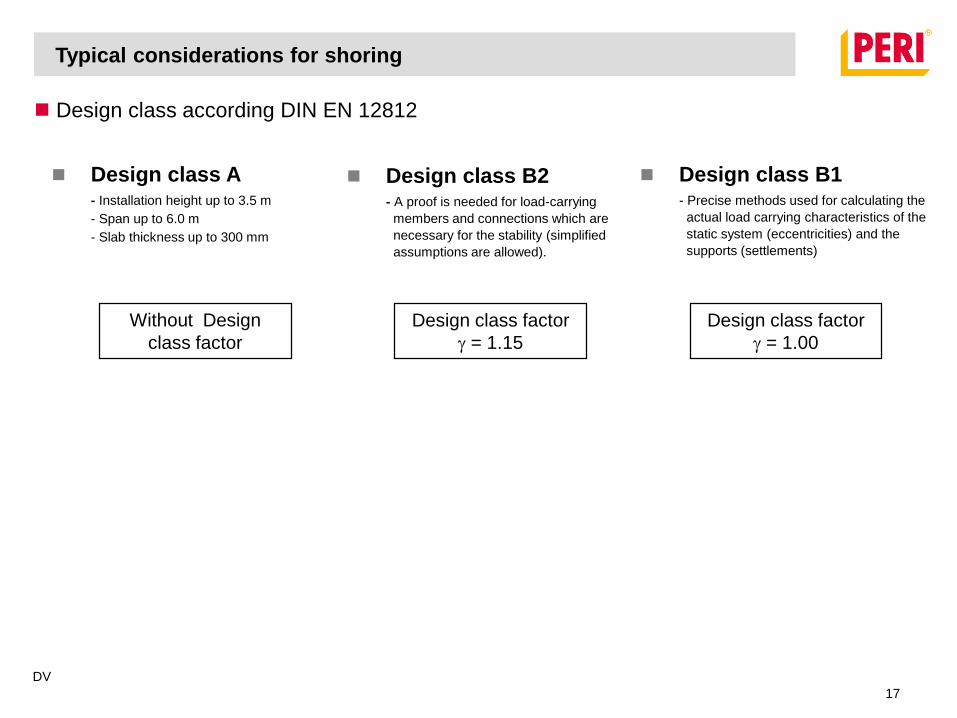
Without Design
class factor
Design class factor
g = 1.15
Design class factor
g = 1.00
Design class A - Installation height up to 3.5 m
- Span up to 6.0 m
- Slab thickness up to 300 mm
Design class B2 - A proof is needed for load-carrying
members and connections which are
necessary for the stability (simplified
assumptions are allowed).
Design class B1- Precise methods used for calculating the
actual load carrying characteristics of the
static system (eccentricities) and the
supports (settlements)
Design class according DIN EN 12812
DV
17
Imperfections and eccentricities
The following influences shall be taken into account
Eccentricities of loads
Angular imperfections and eccentricities caused by looseness
Differences from the theoretical axes (bow and sway)
Typical considerations for shoring
DV
18
Imperfections and eccentricities
Eccentricities of loads
Typical considerations for shoring
DV
19

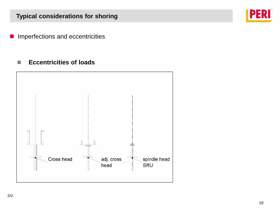
Imperfections and eccentricities
Eccentricities of loads
Typical considerations for shoring
The load eccentricity at load
points shall be taken as a
minimum of 5mm.
DV
20
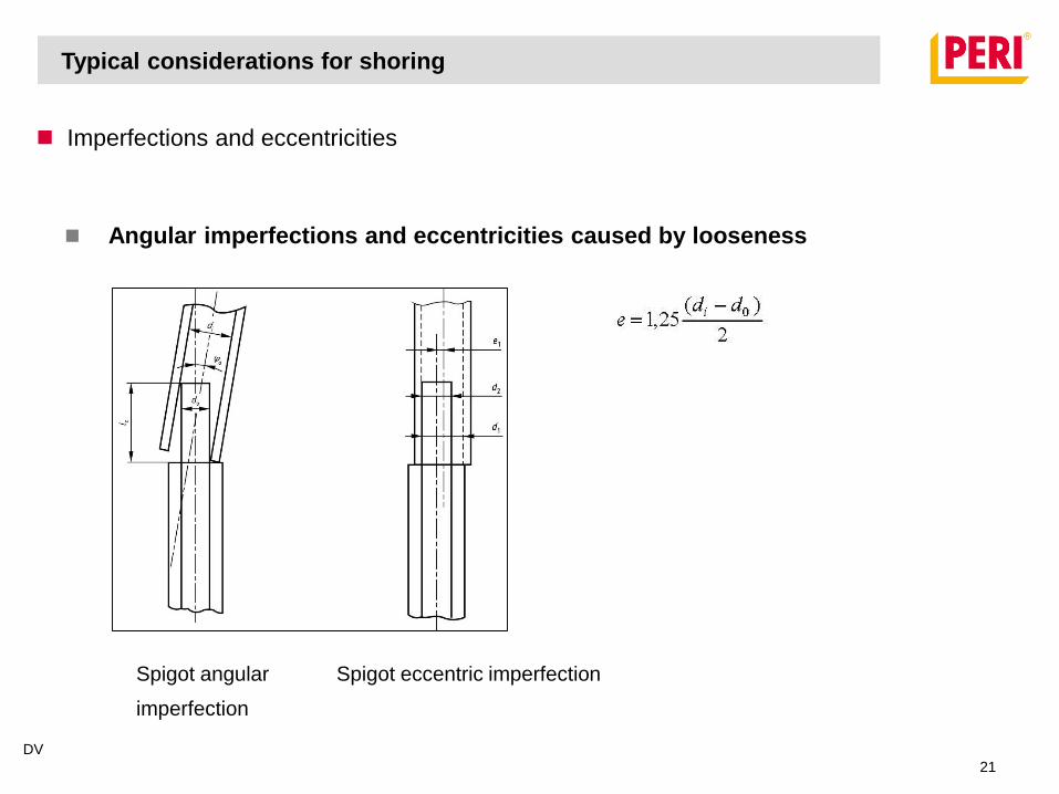
Imperfections and eccentricities
Angular imperfections and eccentricities caused by looseness
Spigot angular
imperfection
Spigot eccentric imperfection
Typical considerations for shoring
DV
21
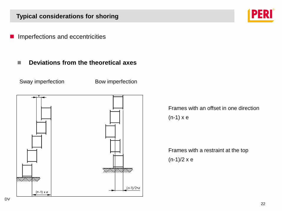
Imperfections and eccentricities
Deviations from the theoretical axes
Sway imperfection Bow imperfection
Frames with an offset in one direction
(n-1) x e
Frames with a restraint at the top
(n-1)/2 x e
Typical considerations for shoring
DV
22

Imperfections and eccentricities
Bow imperfections for compression members
Typical considerations for shoring
DV
23
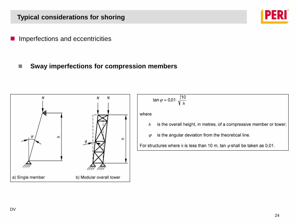
Imperfections and eccentricities
Sway imperfections for compression members
Typical considerations for shoring
DV
24
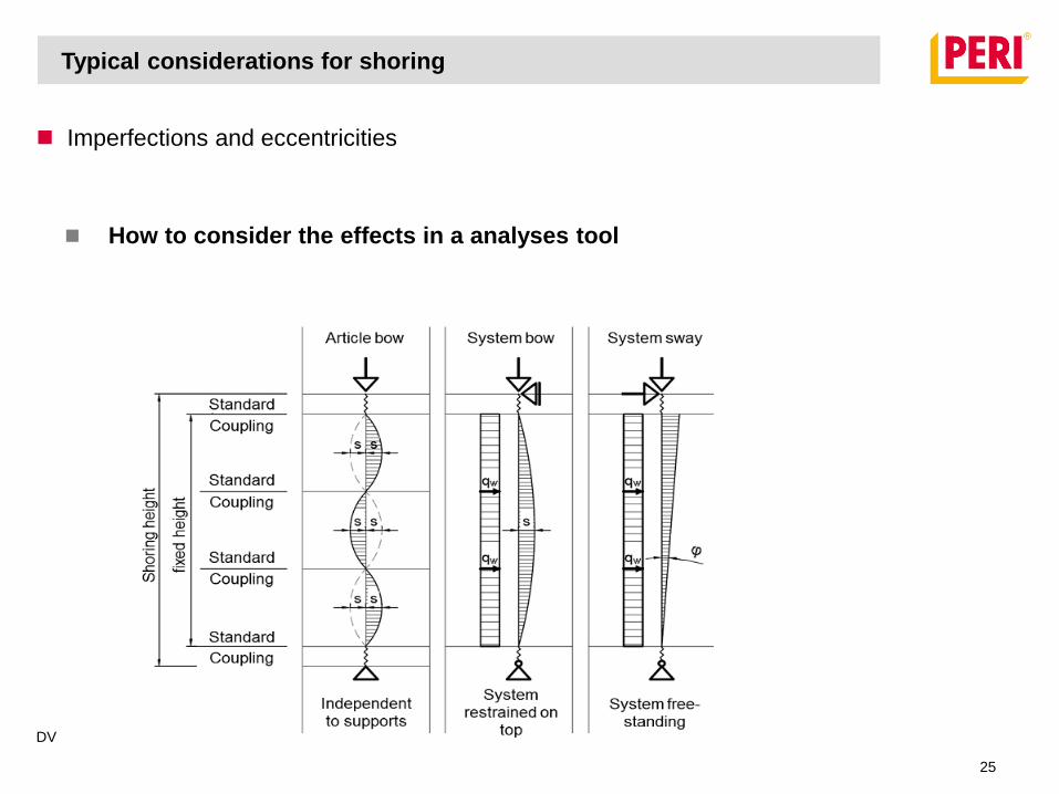
Typical considerations for shoring
Imperfections and eccentricities
How to consider the effects in a analyses tool
DV
25
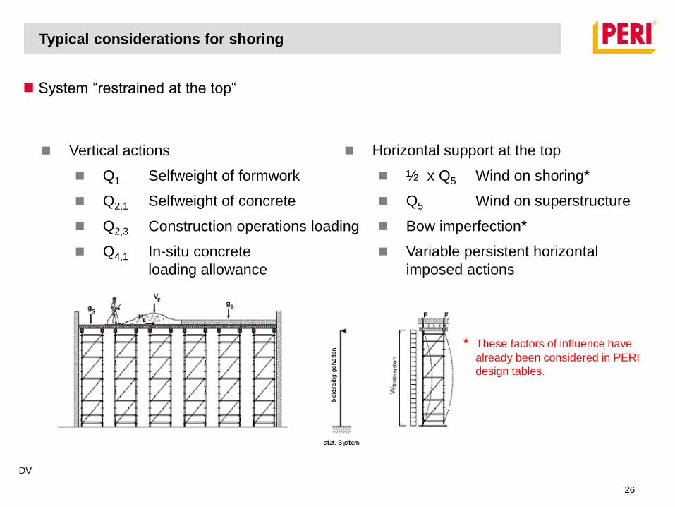
System “restrained at the top“
Typical considerations for shoring
Vertical actions
Q1 Selfweight of formwork
Q2,1 Selfweight of concrete
Q2,3 Construction operations loading
Q4,1 In-situ concrete
loading allowance
Horizontal support at the top
½ x Q5 Wind on shoring*
Q5 Wind on superstructure
Bow imperfection*
Variable persistent horizontal
imposed actions
* These factors of influence have
already been considered in PERI
design tables.
DV
26
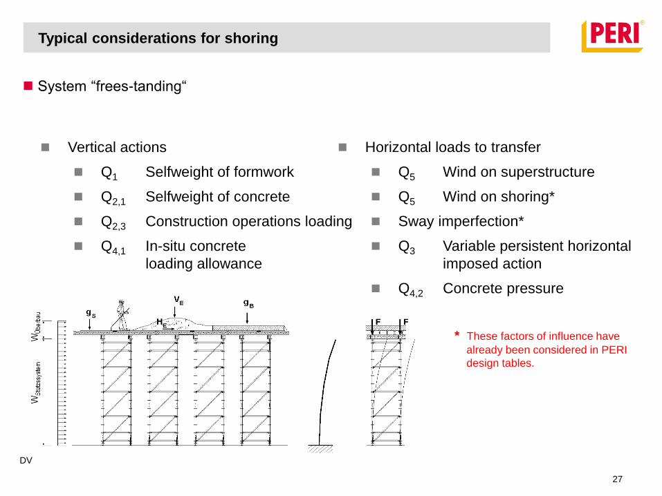
System “frees-tanding“
Vertical actions
Q1 Selfweight of formwork
Q2,1 Selfweight of concrete
Q2,3 Construction operations loading
Q4,1 In-situ concrete
loading allowance
Horizontal loads to transfer
Q5 Wind on superstructure
Q5 Wind on shoring*
Sway imperfection*
Q3 Variable persistent horizontal
imposed action
Q4,2 Concrete pressure
* These factors of influence have
already been considered in PERI
design tables.
Typical considerations for shoring
DV
27
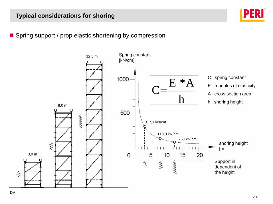
Spring support / prop elastic shortening by compression
3,0 m
8,0 m
12,5 m
Typical considerations for shoring
shoring height
[m]
Spring constant
[kN/cm]
h
A* EC
Support in
dependent of
the height
317,1 kN/cm
118,9 kN/cm
76,1kN/cm
C spring constant
E modulus of elasticity
A cross section area
h shoring height
DV
28
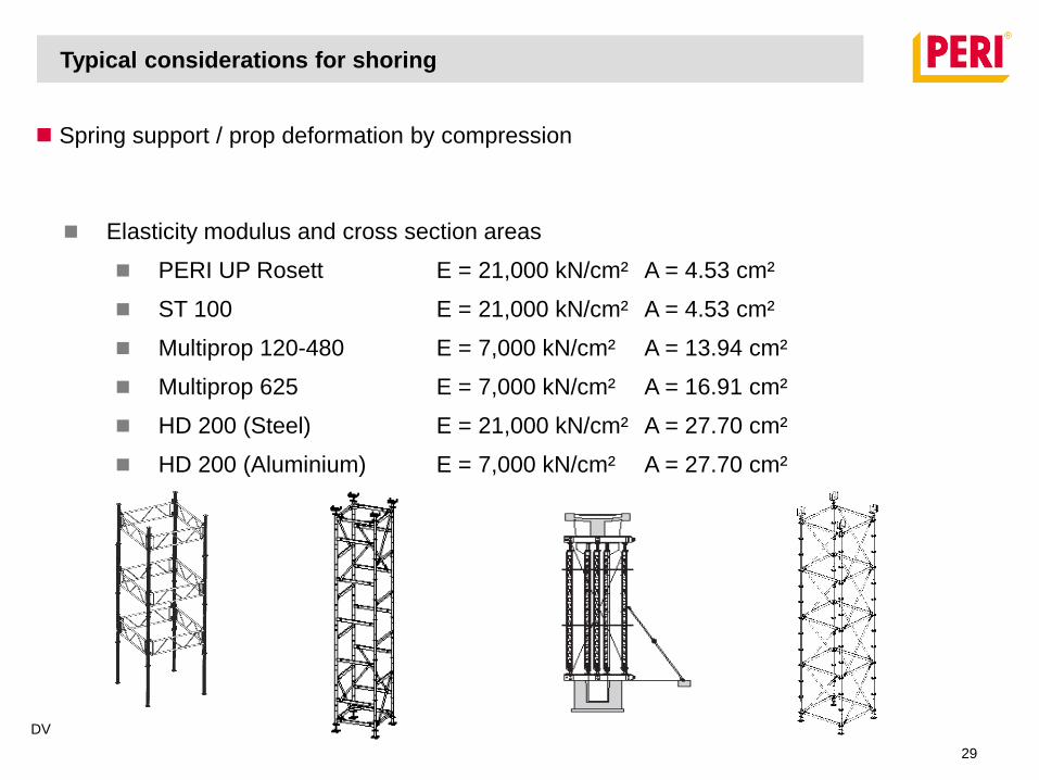
Elasticity modulus and cross section areas
PERI UP Rosett E = 21,000 kN/cm² A = 4.53 cm²
ST 100 E = 21,000 kN/cm² A = 4.53 cm²
Multiprop 120-480 E = 7,000 kN/cm² A = 13.94 cm²
Multiprop 625 E = 7,000 kN/cm² A = 16.91 cm²
HD 200 (Steel) E = 21,000 kN/cm² A = 27.70 cm²
HD 200 (Aluminium) E = 7,000 kN/cm² A = 27.70 cm²
Typical considerations for shoring
Spring support / prop deformation by compression
DV
29
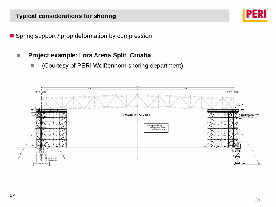
Project example: Lora Arena Split, Croatia
(Courtesy of PERI Weißenhorn shoring department)
Typical considerations for shoring
Spring support / prop deformation by compression
DV
30
Typical considerations for shoring
Spring support / prop deformation by compression
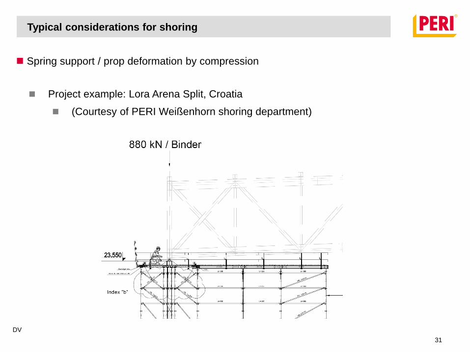
Project example: Lora Arena Split, Croatia
(Courtesy of PERI Weißenhorn shoring department)
DV
31
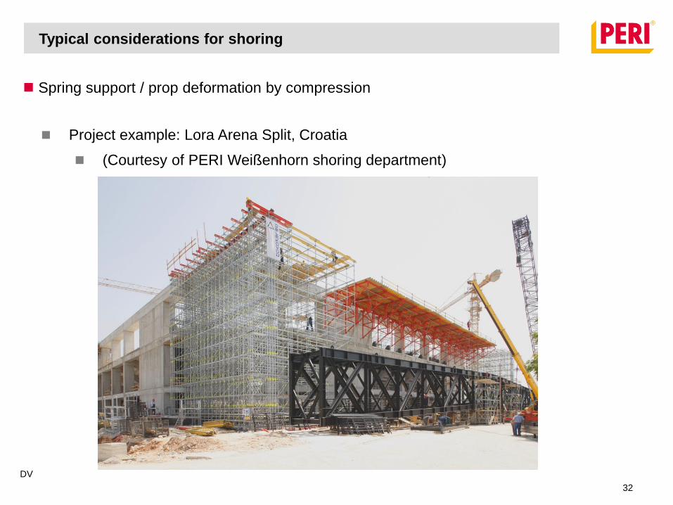
Typical considerations for shoring
Spring support / prop deformation by compression
Project example: Lora Arena Split, Croatia
(Courtesy of PERI Weißenhorn shoring department)
DV
32
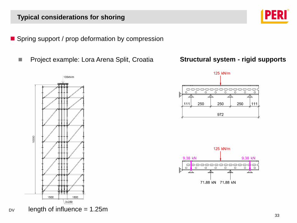
length of influence = 1.25m
Typical considerations for shoring
Spring support / prop deformation by compression
Project example: Lora Arena Split, Croatia Structural system - rigid supports
DV
33
Typical considerations for shoring
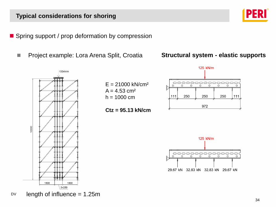
Spring support / prop deformation by compression
Project example: Lora Arena Split, Croatia
length of influence = 1.25m
E = 21000 kN/cm²
A = 4.53 cm²
h = 1000 cm
Ctz = 95.13 kN/cm
Structural system - elastic supports
DV
34

Proof of ULS
The maximum stress induced is a single component must be lower than permissible stress!
Stability has to be provided for the complete system as well as for
every single component.
Ed = design value of an effects of influence
Rd = corresponding design value of resistance
1R
E
d
d
Typical considerations for shoring
DV
35
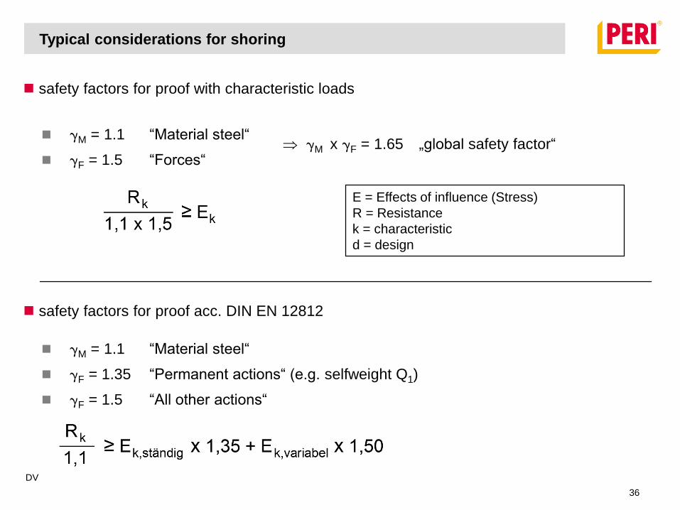
safety factors for proof with characteristic loads
M = 1.1 “Material steel“
F = 1.5 “Forces“ M x F = 1.65 „global safety factor“
E = Effects of influence (Stress)
R = Resistance
k = characteristic
d = design
safety factors for proof acc. DIN EN 12812
M = 1.1 “Material steel“
F = 1.35 “Permanent actions“ (e.g. selfweight Q1)
F = 1.5 “All other actions“
Typical considerations for shoring
DV
36
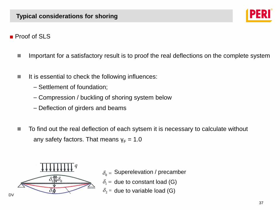
■ Proof of SLS
Typical considerations for shoring
Important for a satisfactory result is to proof the real deflections on the complete system
It is essential to check the following influences:
⎯ Settlement of foundation;
⎯ Compression / buckling of shoring system below
⎯ Deflection of girders and beams
To find out the real deflection of each sytsem it is necessary to calculate without
any safety factors. That means γF = 1.0
Superelevation / precamber
due to constant load (G)
due to variable load (G)DV
37
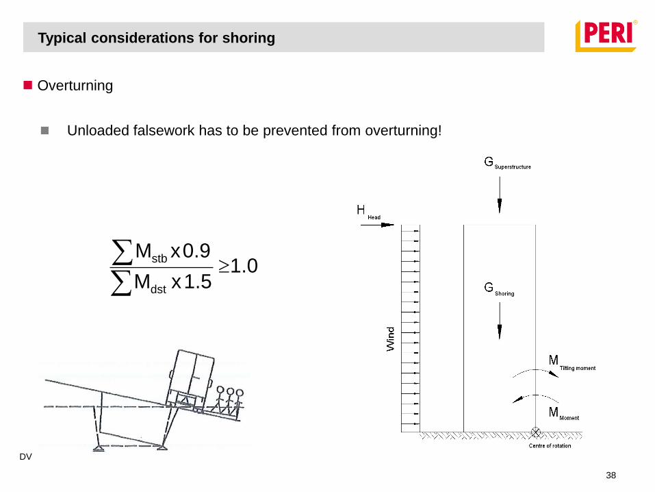
Overturning
Unloaded falsework has to be prevented from overturning!
1.01.5xM
0.9xM
dst
stb
Typical considerations for shoring
DV
38
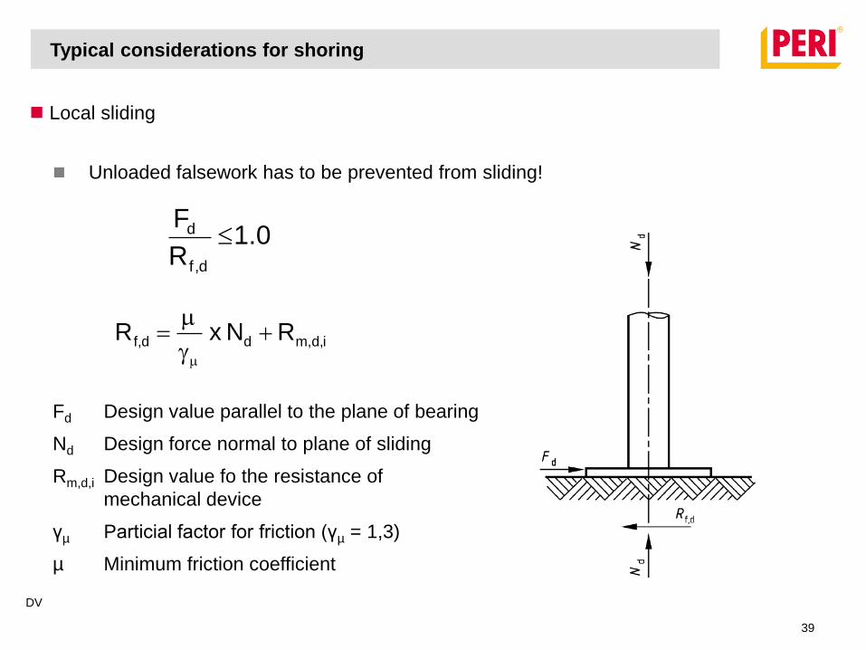
Local sliding
id,m,ddf, R N x R g
1.0R
F
d,f
d
Fd Design value parallel to the plane of bearing
Nd Design force normal to plane of sliding
Rm,d,i Design value fo the resistance of
mechanical device
γµ Particial factor for friction (γµ = 1,3)
µ Minimum friction coefficient
Unloaded falsework has to be prevented from sliding!
Typical considerations for shoring
DV
39
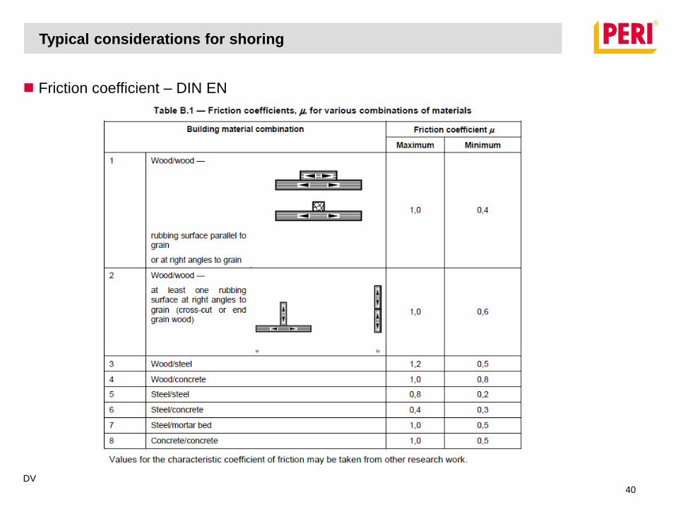
Friction coefficient – DIN EN
Typical considerations for shoring
DV
40
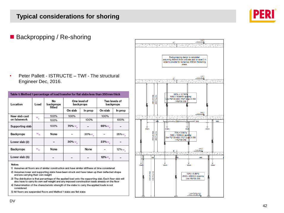
Backpropping / Re-shoring
Typical considerations for shoring
DV
41
• Concrete strength at time of backpropping / Re-shoring
• Sufficient prop capacity under slabs
• Can slab span between props?
• Involve permanent structure engineer for approval of backpropping before
commencing stripping.
• Backpropping percentages.
Backpropping / Re-shoring
Typical considerations for shoring
DV
42
• Peter Pallett - ISTRUCTE – TWf - The structural
Engineer Dec, 2016.

Typical errors and what to look out for on site.
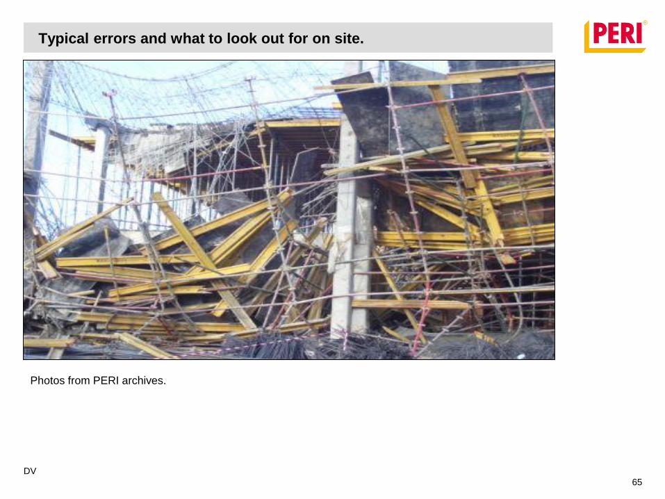
The main causes of formwork failure are:
1 - Improper stripping and shore removal
2 - Inadequate bracing
3 - Vibration
4 - Unstable soil under mudsills* (Sole Plates), shoring not plumb
5 - Inadequate control of concrete placement
6 - Lack of attention to formwork details
DV
43

Typical errors and what to look out for on site.
DV
44
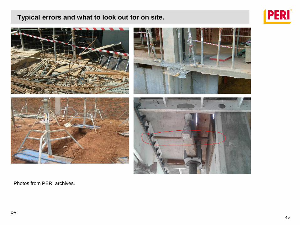
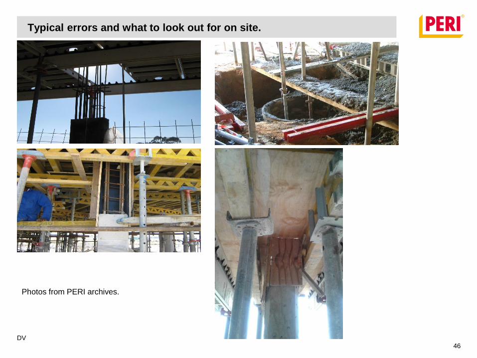
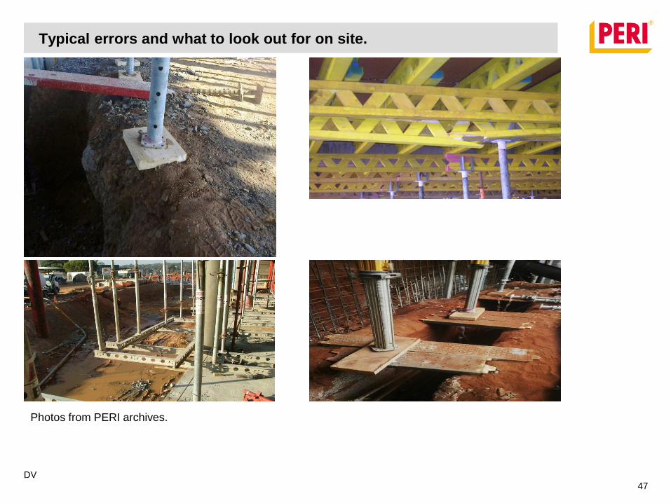
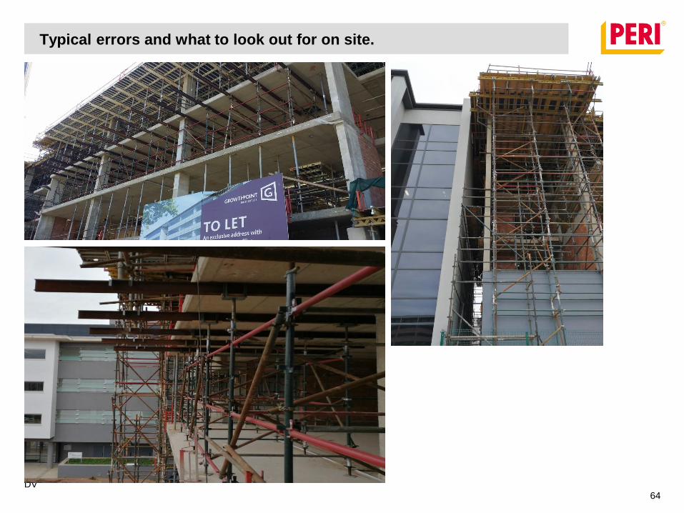
• Failure to install intermediate props.
• Insufficient bracing.
• Correct Bracing installation
• Incorrect grid used.
• Patching around columns.
• Insufficient founding (soil, sole boards etc.)
• Striping and re-propping – Upstand beams
Typical errors and what to look out for on site.
DV
45
Photos from PERI archives.
Typical errors and what to look out for on site.
DV
46
Photos from PERI archives.
Typical errors and what to look out for on site.
DV
47
Photos from PERI archives.
Typical errors and what to look out for on site.
DV
48
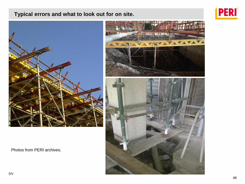
Photos from PERI archives.

Typical errors and what to look out for on site.
DV
49
Photos from PERI archives.
Typical errors and what to look out for on site.
DV
50
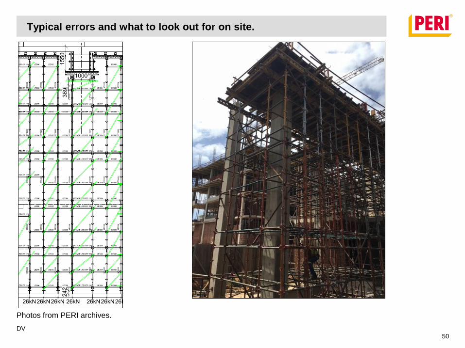
Photos from PERI archives.
Typical errors and what to look out for on site.
DV
51
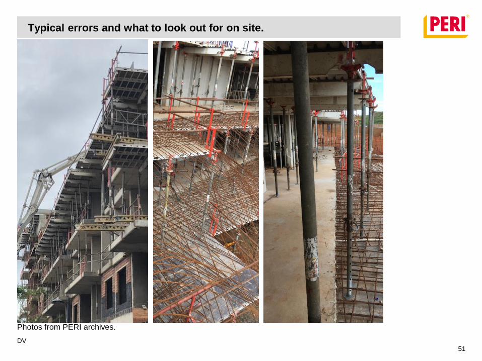
Photos from PERI archives.
Typical errors and what to look out for on site.
DV
52
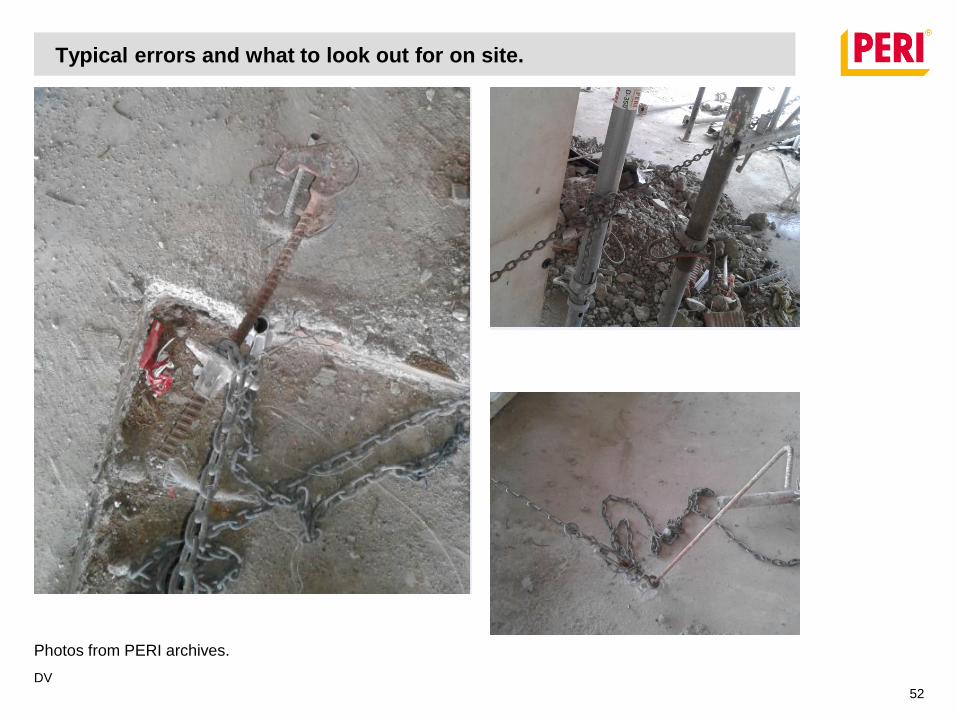
Photos from PERI archives.

Typical errors and what to look out for on site.
DV
53
Bracing 101
A brace must
Be installed at the correct position
Be strong enough
Be stiff enough

Typical errors and what to look out for on site.
DV
54
Bracing 101 – Quickstage example
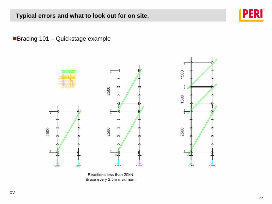
Typical errors and what to look out for on site.
DV
55
Bracing 101 – Quickstage example
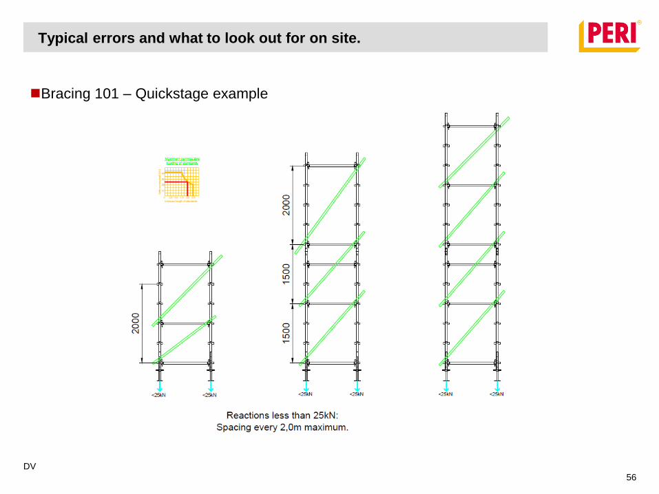
Typical errors and what to look out for on site.
DV
56
Bracing 101 – Quickstage example
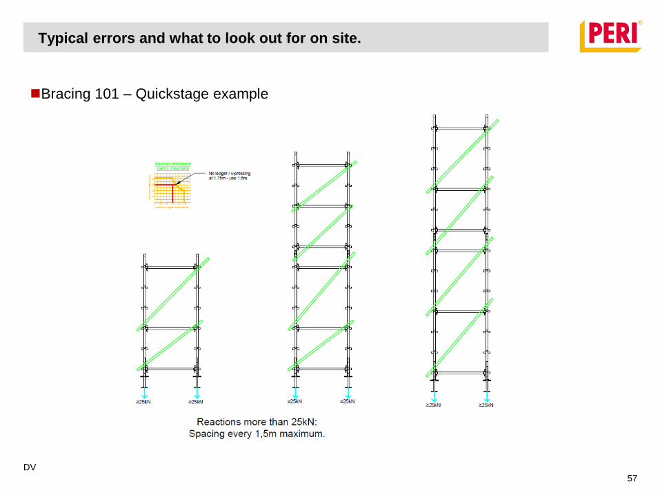
Typical errors and what to look out for on site.
DV
57
Bracing 101 – Quickstage example
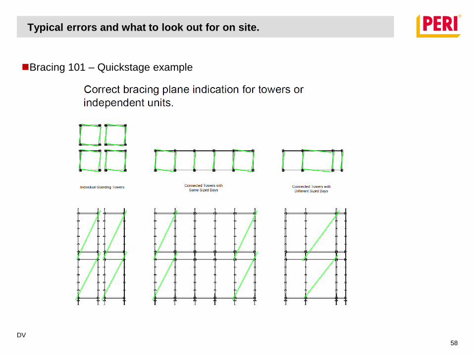
Typical errors and what to look out for on site.
DV
58
Bracing 101 – Quickstage example

Typical errors and what to look out for on site.
DV
59
Bracing 101 – Quickstage example
Typical errors and what to look out for on site.
DV
60
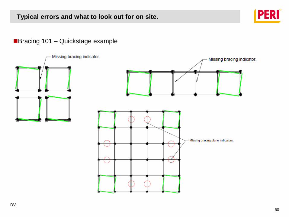
Bracing 101 – Quickstage example
Typical errors and what to look out for on site.
DV
61
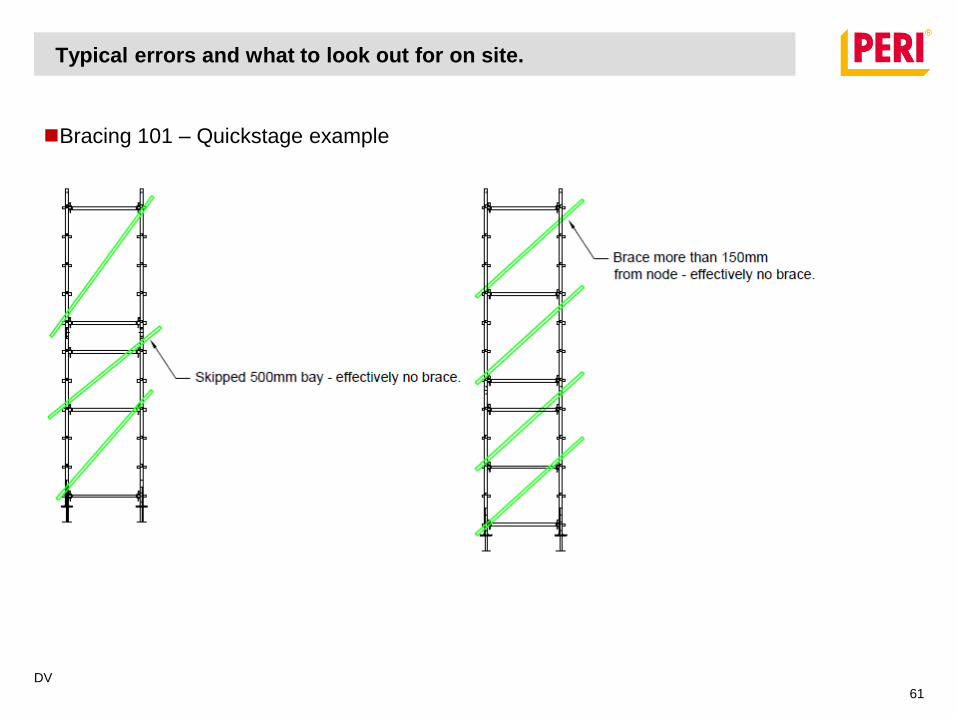
Bracing 101 – Quickstage example
Typical errors and what to look out for on site.
DV
62
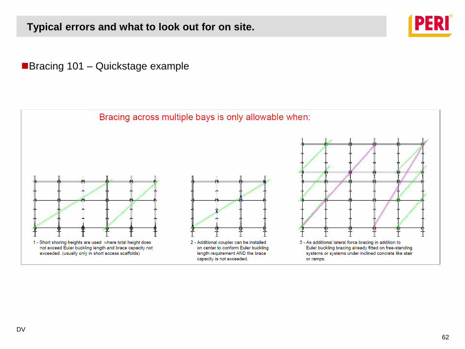
Bracing 101 – Quickstage example
Typical errors and what to look out for on site.
DV
63
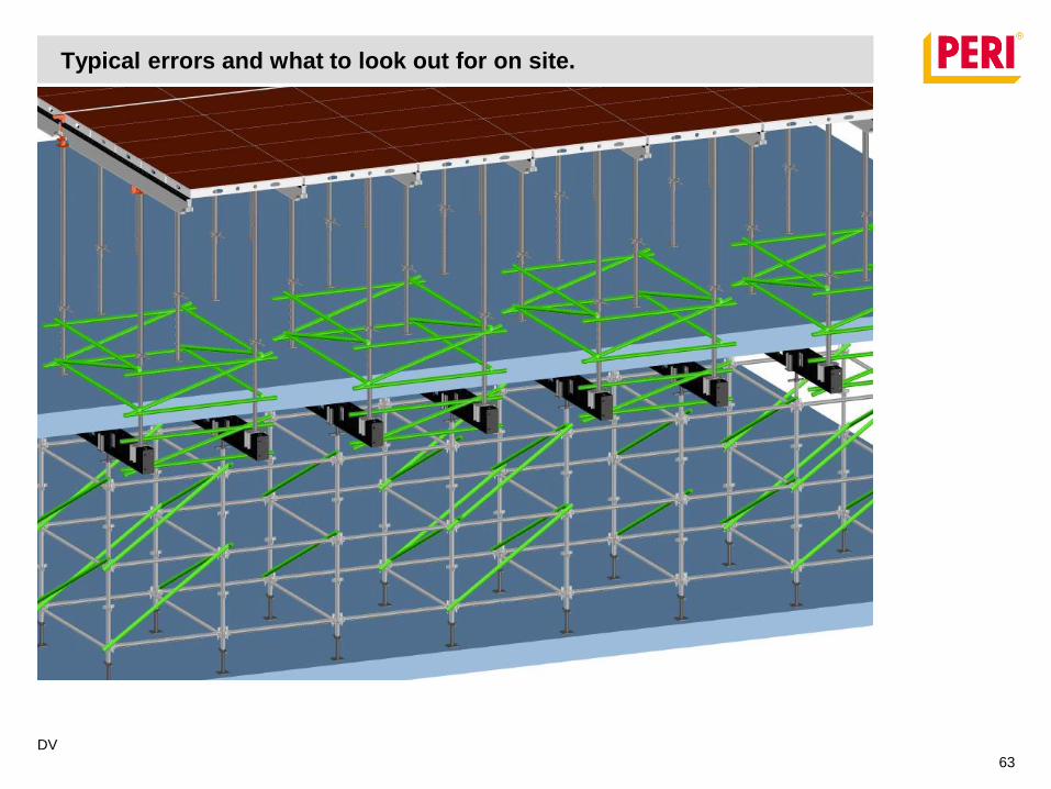
Typical errors and what to look out for on site.
DV
64
Typical errors and what to look out for on site.
DV
65
Photos from PERI archives.
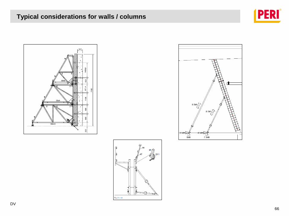
Typical considerations for walls / columns
DV
66
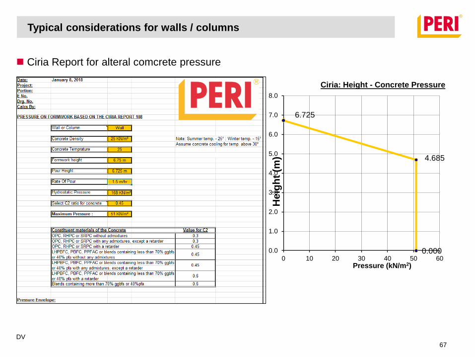
Ciria Report for alteral comcrete pressure
Typical considerations for walls / columns
DV
67
0.000
4.685
6.725
0.0
1.0
2.0
3.0
4.0
5.0
6.0
7.0
8.0
0 10 20 30 40 50 60
He
igh
t (m
)
Pressure (kN/m2)
Ciria: Height - Concrete Pressure
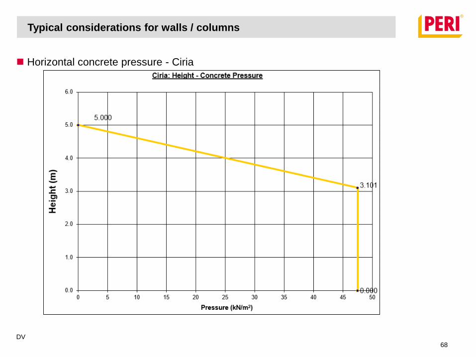
Horizontal concrete pressure - Ciria
Typical considerations for walls / columns
DV
68
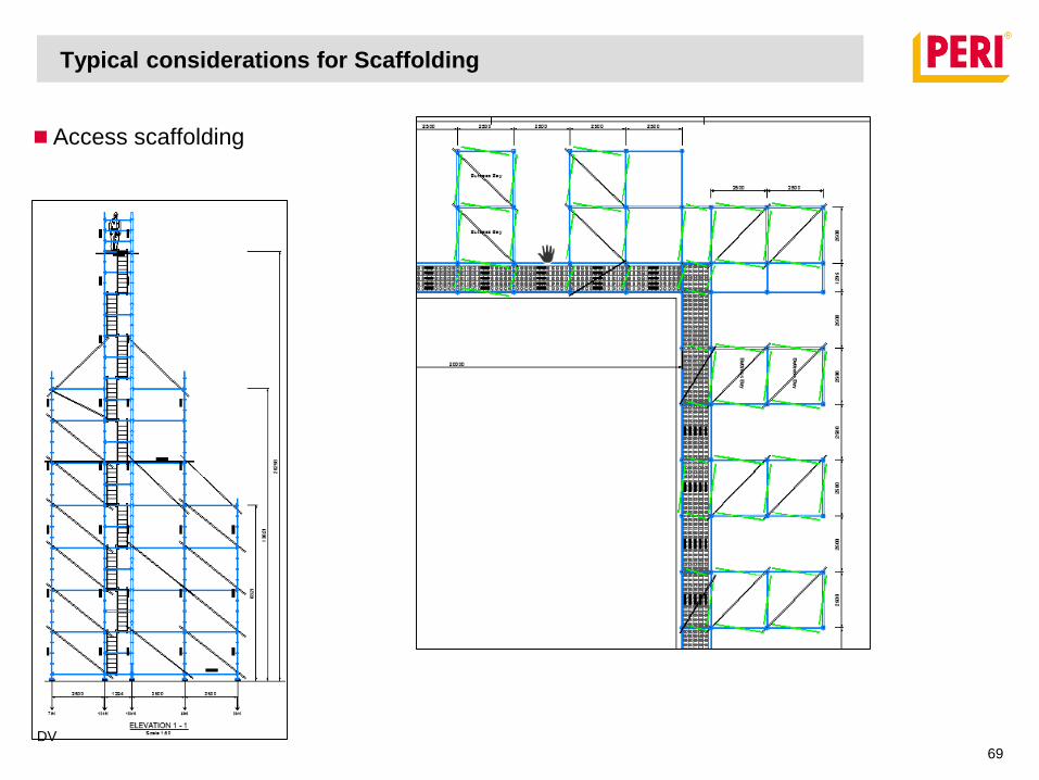
Typical considerations for Scaffolding
Access scaffolding
DV
69

Typical considerations for Scaffolding
Access scaffolding
DV
70
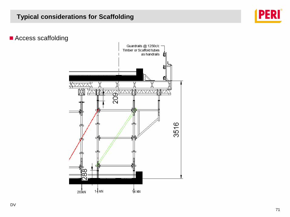
Typical considerations for Scaffolding
Access scaffolding
DV
71

Typical considerations for Scaffolding
DV
72
Important Extracts from SANS10085-1:2005
For knots, refer to 6.3.3

Typical considerations for Scaffolding
DV
73
Important Extracts from SANS10085-1:2005
This is a good practise guideline – designers should still calculate stability.
For stability ratios refer to Table 3.
Typical considerations for Scaffolding
DV
74
Important Extracts from SANS10085-1:2005
Take care of maximum allowed number of platforms – usually 2x working platforms.
For classification refer to Table 5.
Typical considerations for Scaffolding
DV
75
Important Extracts from SANS10085-1:2005
For deviations refer to 10.1.4
Typical considerations for Scaffolding
DV
76
Important Extracts from SANS10085-1:2005
For scaffold boards refer to Table 6
Typical considerations for Scaffolding
DV
77
Important Extracts from SANS10085-1:2005
For ladders refer to 10.7
Typical considerations for Scaffolding
DV
78
Important Extracts from SANS10085-1:2005
For ledgers refer to Table 9
For Maintenance and housekeeping refer to 11.4

Typical considerations for Scaffolding
DV
79
Important Extracts from SANS10085-1:2005
For inspection refer to Clause 12

Typical considerations for Scaffolding
DV
80
16.2 Training of Scaffolding erector to Inspector.
SANS details the minimum required training program and experience.
For training refer to 16.2.5
Thank You.
Questions?
DV
81
Flanders Drive
bridge over R102.

References
Shoring presentation extracts, PERI Weißenhorn shoring department.
PERI RSA local project photos, PERI photo archives.
PERI international project photos, www.peri.com
Table extracts, DIN EN 12812, SANS10085-1:2005.
Graph extracts, DIN EN 12812.
Beaufort wind scale, Francis Beaufort.
DV
82