Embed Size (px)
Citation preview

i
GROUP 28
Maze Twinbots
Uyen Nguyen, Ly Nguyen, Luke Ireland
Fall 2014 - Spring 2015

ii
Table of Contents 1 Executive Summary ...................................................................................... 1
2 Motivation and Goals ..................................................................................... 2
3 Requirements/Specifications ......................................................................... 3
3.1 Motor ....................................................................................................... 3
3.2 Wheels and Chassis ................................................................................ 3
3.3 Power Supply .......................................................................................... 4
3.4 Sensor ..................................................................................................... 4
4 Identification and Review of Applicable Standards ........................................ 6
4.1 IEC 61249-2-23 Ed. 1.0 b:2005 [5] .......................................................... 6
4.2 IEC/TS 62657-1 Ed. 1.0 en:2014 [5] ....................................................... 6
4.3 CISPR/TR 28 Ed. 1.0 b:1997 [5] ............................................................. 7
5 Research ....................................................................................................... 7
5.1 Motor ....................................................................................................... 7
5.1.1 Center and Modify Servo .................................................................. 8
5.2 Encoder ................................................................................................... 9
5.3 Sensor ................................................................................................... 12
5.3.1 Photoelectric Sensor ....................................................................... 14
5.4 Microcontroller ....................................................................................... 15
5.5 Power Supply ........................................................................................ 19
5.6 Voltage Regulator .................................................................................. 19
5.7 Communication Hardware ..................................................................... 20
5.7.1 Infrared Communication .................................................................. 21
5.7.2 Bluetooth ......................................................................................... 22
5.7.3 RF Communication ......................................................................... 22
5.7.4 Decision .......................................................................................... 25
5.7.5 CC110L Transceiver ....................................................................... 26
5.8 Integrated Development Environment (IDE) .......................................... 28
5.9 Maze Solving Algorithms ....................................................................... 28
6 Initial Hardware Design ............................................................................... 32
6.1 Voltage Regulation and Protection Circuit ............................................. 32
6.1.1 Boost Regulator Circuit Design ....................................................... 37
6.1.2 Buck/Boost Regulator Circuit Design .............................................. 38
6.1.3 Linear Regulator Circuit Design ...................................................... 41
iii
6.1.4 Microcontroller Interfaces ................................................................ 43
6.1.5 Sensor Connection ......................................................................... 46
6.2 System Integration ................................................................................ 46
7 Initial Software Design ................................................................................. 48
7.1 Wall Following Algorithm ....................................................................... 48
7.2 Control System ...................................................................................... 54
7.3 Movement Control ................................................................................. 56
7.4 CC110L Transceiver Analysis ............................................................... 60
7.4.1 Data Transfer .................................................................................. 61
7.4.2 Microcontroller Interface ................................................................. 62
7.4.3 Packet Handling .............................................................................. 62
7.5 Software Integration .............................................................................. 63
7.5.1 Communication Integration ............................................................. 69
8 Prototyping and Testing .............................................................................. 70
8.1 Breadboarding ....................................................................................... 71
8.2 Printed Circuit Board (PCB) Design ...................................................... 73
8.2.1 Voltage Regulator Layout ............................................................... 73
8.2.2 Final Power Supply Design ............................................................. 74
8.2.3 Anaren AIR Module Layout ............................................................. 75
8.2.4 Program Microcontroller on PCB .................................................... 76
8.2.5 Final Programming Interface Design ............................................... 77
8.2.6 Soldering ......................................................................................... 78
8.2.7 Final Hardware Design ................................................................... 81
8.3 Working with Motors .............................................................................. 83
8.3.1 Centering Servos ............................................................................ 83
8.3.2 Motor Tests ..................................................................................... 85
8.4 Interpret Sensor Data ............................................................................ 87
8.4.1 Resolving Sensor Issues ................................................................ 92
8.5 Maze Construction ................................................................................ 93
8.6 Navigation ............................................................................................. 94
8.6.1 Prototype Construction for Testing .................................................. 96
8.6.2 Navigation Problems and Solutions ................................................ 97
8.7 Algorithm Implementation ...................................................................... 98
8.7.1 Simplification ................................................................................... 98

iv
8.7.2 Solving the Maze ............................................................................ 98
8.7.3 Finding the Exit ............................................................................. 103
8.7.4 Resolving Communication Issues ................................................. 104
9 Impact of Design Constraints Imposed by Applicable Standards .............. 105
10 Project Operation .................................................................................... 105
10.1 Uploading Maze Solving Program .................................................... 105
10.2 Add I/O Pins Not Recognized by Energia ........................................ 106
10.3 Configure the Maze .......................................................................... 108
10.4 Robot Operation ............................................................................... 108
10.5 Final Assembly ................................................................................. 110
11 Administrative Content ............................................................................ 111
11.1 Team Management .......................................................................... 111
11.2 Senior Design 1 Project Milestone ................................................... 112
11.3 Budget and Financing ...................................................................... 115
12 Conclusion .............................................................................................. 119
References ............................................................................................................ I
Appendices ......................................................................................................... VII
Appendix A Bibliography ................................................................................. VII
Appendix B Copyright Permissions ................................................................ VIII
Digi-Key ...................................................................................................... VIII
ElectronicsTutorials .................................................................................... VIII
Texas Instruments ...................................................................................... VIII
Anaren .......................................................................................................... IX

1
1 Executive Summary The Twinbots project is a project that is designed mainly for the intellectual/ experiential gain of the design team members. However, there is also a realization that this project has some inherent flexibility for application such as: reconnaissance, search and rescue, etc. To demonstrate this flexibility the project will create two robots that will solve a maze in tandem using two separate maze solving algorithms. Since both robots will be using different algorithms to solve the maze we assume that for a given configuration one robot will be faster than the other one. To ensure that the robots work as a “team” they will be designed with Sub GHz RF communication modules so that the faster of the two robots can communicate the solution back to the other robot. While each robot is completing the maze they will store each turn and the after each run is completed they will each analyze the solution and optimize based on certain criteria. The goal of this project is to create both robots to be small, consume low power, be inexpensive, and have a 90% success rate when solving the maze. The robots should also be able to figure out the optimal solution through a maze in no more than five runs. A majority of this project is intended to be a learning process for the team members considering the fact that none of the members has extensive experience in any field. Therefore, some basic skills like soldering, PCB design and reading sensor data will be integral portions of the project. To accomplish all of these things the design team has researched every aspect of the project in an effort to minimize mistakes and successfully complete the project on time. This include researching what type of microcontroller to use, what kind of sensor should be used, and the kind of motors to be used to drive the wheels. There was also research on control theory to be implemented on the motors as well as the frequency at which to transmit RF signals. Special attention has also been given to system protection from accidental short circuits or overcurrent faults through the research and implementation of protective circuits. These circuits are one of the most important parts of the project since they can protect the entire system from a mistake or accident that occurs in any one of the subsystems and will preserve the individual components in the event of any problems. Comparisons have been made between alternative solutions to these issues and final decisions have been made and then clarified to illustrate how the team came to these conclusions. Throughout this report there will be information about how certain subsystems have been designed and how they will be integrated across the entire system. This starts after the research phase with simple block diagrams that illustrate how subsystems are arranged and culminates with the PCB design where all components are interfaced together to from the motherboard of the entire project.

2
2 Motivation and Goals Robotics is a technology that most of us don’t see in our daily life. However, it is still a very important technology that is used widely. Robots are used to access areas that are dangerous to humans, such as in space exploration or human rescue. Robots are used in manufacturing processes as well. In recent years, other countries use robots in customer service or as companions for elder people. To construct a robot, different areas of engineering come into play. The robotic body requires the knowledge of mechanical engineers since it consists mostly of moving parts. To connect the electronic parts together and process data from the surrounding environment, we need the skills of electrical engineers. To help the robots develop some kind of decision-making ability, we need to create artificial intelligence which serves as the robot’s brain. This falls into the field of computer science. The maze-solving robot sounds like a hobbyist project. However, the concept can apply to real life situation. For an example, if a person is trapped in a place where he or she doesn’t know the location of the exit, a robot can be sent in to lead the person to the outside. Our group wants to do a project that involves a variety of fields in electrical engineering. All the members of the group like electronics so we imagined we can do something with circuits. We came up with the robot idea because it’s big enough to be interesting and small enough to be accomplished by a three-member group. This project can be divided into three parts: hardware, software, and communication. For the hardware part, we need to build protection and regulation circuit for the sensor and the microcontroller. The software part involves writing maze-solving algorithm in programming language. The communication part is where we need to transmit signals between the two robots. There are a lot of robot projects out there such as paint-spraying robots or fire-rescue robots. We chose the maze-solving robots because we like the puzzle-solving aspect of it. A project similar to this one is the line-following robot, which solves a two-dimensional maze by tracing the black lines against a white background. We thought a three-dimensional maze is more real and more difficult to implement. In a three-dimensional maze, it is harder for the robot to turn around because it may hit the wall or get stuck. For the line-following robot, only one sensor array is needed at the bottom of the robot to scan the line. For the wall-following robot, we need to set up multiple sensors at different angles so that the robot can scan a 180° frontal area. Our goal is to create a low-cost and energy-efficient robot that can navigate through a maze autonomously. Most of the robot parts are made from microelectronics so the power consumption is very small. Memory usage also links to the efficiency issue. We would like to write a maze-solving algorithm that uses as little memory as possible.

3
3 Requirements/Specifications The robot can be divided into 3 major categories.
Hardware - sensors, microcontroller, protection and regulation circuit, chassis, wheels, mounting parts, battery, and motors.
Software – memory, maze-solving libraries, integrated development environment (IDE) for designing PCB (printed circuit board) and executing maze-solving algorithm.
Communication – protocols and radio module.
3.1 Motor It’s preferable to choose a motor that is light. Since the robot is designed to be small, the motor should be small enough to fit under a chassis. Smaller motor would require lower current [1]. High torque is better than low torque to handle the robot’s overall load. The motor’s speed shouldn’t be too high in order for sensor to have adequate time to respond to the surrounding environment or too low so that the robot has sufficient time to find a way out of a maze. With the purpose of designing low-power robot, the motor is selected to operate in a low voltage range. However, the voltage shouldn’t be too low to prevent the torque and speed being reduced significantly [2]. It’s desirable that the motor doesn’t draw a huge amount of current out of batteries when the motor shaft stalls. Gears play a major factor in weight and torque. Metal gears are known to be stronger but heavier than plastic gears [3]. Figure 3-1 lists the required range of torque, weight, voltage, and speed for the motors. The type of motor that will be used is determined through research.
Torque 2 – 10 kg-cm
Weight < 55 g
Voltage 4 – 6 V
Speed 30 – 50 RPM
Length x Width x Height ≤ 7 cm x ≤ 3 cm x ≤ 3 cm
Figure 3-1: Motor specifications
3.2 Wheels and Chassis Since wheels are the only mechanical moving parts on the robots, motors will be attached to the wheels to control movement. Bigger wheels allow faster movement but can’t support heavier load because they have less torque. For instance, a 4 kg-cm motor produces 4 kg of force at the end of a wheel with 1-cm radius. A 0.5-cm radius can support 8 kg of force. Thus, A 2-cm wheel can only support 2 kg of force. Smaller wheels are ideal for fine positional control since they can keep up with changes in position well but take longer to solve the maze [4]. As a result, the team should consider the tradeoffs before deciding on the
4
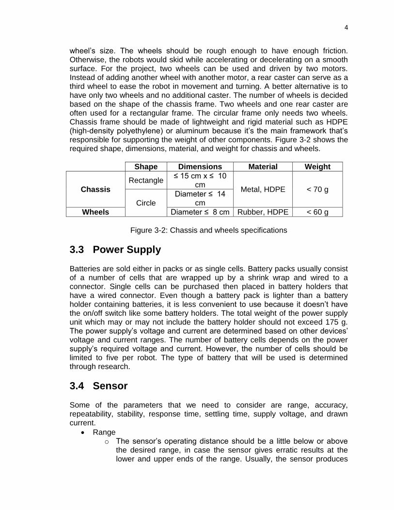
wheel’s size. The wheels should be rough enough to have enough friction. Otherwise, the robots would skid while accelerating or decelerating on a smooth surface. For the project, two wheels can be used and driven by two motors. Instead of adding another wheel with another motor, a rear caster can serve as a third wheel to ease the robot in movement and turning. A better alternative is to have only two wheels and no additional caster. The number of wheels is decided based on the shape of the chassis frame. Two wheels and one rear caster are often used for a rectangular frame. The circular frame only needs two wheels. Chassis frame should be made of lightweight and rigid material such as HDPE (high-density polyethylene) or aluminum because it’s the main framework that’s responsible for supporting the weight of other components. Figure 3-2 shows the required shape, dimensions, material, and weight for chassis and wheels.
Shape Dimensions Material Weight
Chassis Rectangle
≤ 15 cm x ≤ 10 cm
Metal, HDPE < 70 g
Circle Diameter ≤ 14
cm
Wheels Diameter ≤ 8 cm Rubber, HDPE < 60 g
Figure 3-2: Chassis and wheels specifications
3.3 Power Supply Batteries are sold either in packs or as single cells. Battery packs usually consist of a number of cells that are wrapped up by a shrink wrap and wired to a connector. Single cells can be purchased then placed in battery holders that have a wired connector. Even though a battery pack is lighter than a battery holder containing batteries, it is less convenient to use because it doesn’t have the on/off switch like some battery holders. The total weight of the power supply unit which may or may not include the battery holder should not exceed 175 g. The power supply’s voltage and current are determined based on other devices’ voltage and current ranges. The number of battery cells depends on the power supply’s required voltage and current. However, the number of cells should be limited to five per robot. The type of battery that will be used is determined through research.
3.4 Sensor Some of the parameters that we need to consider are range, accuracy, repeatability, stability, response time, settling time, supply voltage, and drawn current.
Range o The sensor’s operating distance should be a little below or above
the desired range, in case the sensor gives erratic results at the lower and upper ends of the range. Usually, the sensor produces

5
very high voltage when detecting close objects and that can give false reading.
Accuracy o Ideally, it should not deviate a lot from the standard values. We will
have to gather a lot of data and graph it in order to see the overall pattern.
Repeatability o It should be able to produce the same results in the same
environment.
Stability o The sensor should be able to give the same output for a given
input. This is a photoelectric sensor so interference can come from ambient light. It’s important to choose a high-quality sensor that is immune to sunlight. Ideally, the sensor should not be affected by the object’s color.
Response time o The sensor should take about 30 to 40 milliseconds to respond. If
the response time is too quick, the electronics will not be able to process the signals quick enough. If the response time is too slow, it will take a long time for the robot to move and exit out the maze.
Continuity o It’s better if the sensor can continuously take in data, so that there’s
no delay in data processing.
Settling time o Settling time is the time it takes for the sensor to reach a stable
output once it’s turned on. The data collected at the settling time should be discarded. The settling time should be around 30 to 50 milliseconds.
Supply voltage o If the voltage is too high, the sensor will burn out. If the voltage is
too low, the sensor won’t work correctly. Supply voltage should be several volts, around 3 volts to 7 volts.
Current o Power is the product of voltage and current. Therefore, to keep a
constant power, current must be kept relatively small and voltage must be relatively high. When the battery discharges, the voltage decreases and the current increases. This may cause the sensor to burn out. Therefore, we need a protection circuit connected to the sensor if it’s not already provided with the sensor.
Signal output voltage o If the output voltage is analog, we need an analog-to-digital
converter if it’s not already provided with the microcontroller. If the output voltage is smaller than what is needed for the microcontroller, we may need an amplifier. If it is higher than what is needed, we may need a voltage regulator.

6
4 Identification and Review of Applicable Standards
4.1 IEC 61249-2-23 Ed. 1.0 b:2005 [5] Title: Materials for printed boards and other interconnecting structures - Part 2-23: Reinforced base materials, clad and unclad - Non-halogenated phenolic cellulose paper reinforced laminated sheets, economic grade, copper clad" Scope: This part of IEC 61249 gives requirements for properties of non-halogenated phenolic cellulose paper copper-clad laminated sheets, economic grade, in thicknesses of 0,8 mm up to 3,2 mm. This standard covers materials with different requirements on flammability and is designated according to the following: Material 61249-2-23-1: general purpose grade, requirement on flammability not specified; Material 61249-2-23-2: materials of defined flammability (vertical burning test). These grades of material provide for one of two flammability requirements and designated as FV0 or FV1.
4.2 IEC/TS 62657-1 Ed. 1.0 en:2014 [5] Title: Industrial communication networks - Wireless communication networks - Part 1: Wireless communication requirements and spectrum considerations IEC TS 62657-1:2014(en) provides the wireless communication requirements dictated by the applications of wireless communication systems in industrial automation, and requirements of related context. The requirements are specified in a way that is independent of the wireless technology employed. The requirements are described in detail and in such a way as to be understood by a large audience, including readers who are not familiar with the industry applications. Social aspects, environmental aspects, health aspects and market requirements for wireless communication systems in industrial automation are described to justify the wireless communication requirements. This Technical Specification describes requirements of the industrial automation applications that can be used to ask for additional dedicated, worldwide unique spectrum. This additional spectrum is intended to be used for additional wireless applications while continuing using the current ISM bands.
7
4.3 CISPR/TR 28 Ed. 1.0 b:1997 [5] Title: Industrial, scientific and medical equipment (ISM) - Guidelines for emission levels within the bands designated by the ITU (International Telecommunication Union) This technical report provides the guidelines for emission levels within the bands designated by the International Telecommunication Union (ITU) for industrial, scientific and medical (ISM) application.
5 Research
5.1 Motor A motor is necessary to power all the moving parts on the robot, mainly the wheels. Upon choosing a motor, three motor types are considered: servo, stepper, and direct current (DC) motors. DC motor is most commonly used in applications that require fast continuous rotations [6]. However, the high speed characteristic is not advantageous to the project. In order to reverse and control the speed of a DC motor, an H bridge is commonly used to reverse the direction of the current in the motor [7]. The addition of an H bridge would complicate the circuitry. DC motor is ideal for speed control using pulse width modulation [6]. A servo is ideal when selecting a motor that functions similar to a DC motor but also possesses characteristics of stepper motor. It’s favored over the DC motor because its position control is more precise and over the stepper motor due to its quiet operation and small sizes [8] [9]. Nevertheless, it’s more expensive and more complicated to setup than stepper motor since it requires tuning. One major drawback when using the servo for the robot’s wheels is its limited rotation range (up to 180 degrees). However, few manufacturers do offer continuous-rotation servos. Users can also modify the servos themselves. Some servos are harder to modify than others. Digital servos update position at a faster rate, typically 300 Hz, than analog counterparts, which update position at 30 Hz. Digital servos also generally have higher torque and smaller size than analog ones. However, digital servos cost much more than analog servo even though there’s no main component difference between the two [10]. A stepper motor has several advantages over the other two servos. Among the three motors, it's known to be the most precise one, which is desirable for the project since precision is crucial for obstacle avoidance. Whereas servo requires a feedback positioning control, a stepper motor drives positioning through its open loop. It requires no tuning and easy to set up and control. In addition, it can provide a constant holding torque without the need to be powered. Stepper motors are generally cheaper than servo motors. As good as it sounds, a stepper motor does have its downsides. It’s slow and noisy. Moreover, it requires an

8
external control circuit to make the motor shaft turn. It consumes current regardless of load. Since it lacks the control loop, stepper motor can stall or lose position when it runs. Stepper motor is available in two varieties: unipolar and bipolar. Bipolar is favored for the project because it generally has more torque than unipolar one. [6] [8] After careful consideration of the three motor types’ advantages and disadvantages, servo is chosen to control the robot’s wheels because of multiple reasons. Servo motor does not require an external H bridge or control circuit like stepper and DC motors. Servo’s speed is moderate, making it desirable for our project. It’s not as fast as DC motor or as slow as a stepper motor. Servo may be more expensive than the other two but the price difference is not very large. A Parallax standard servo is already acquired. Therefore, we have one less motor to buy. Besides pulse width modulation (PWM), which can be utilized in any of the motor type, the team will also gain experience if we decide to modify a standard servo for continuous rotation.
5.1.1 Center and Modify Servo Before modifying a servo, it’s necessary to understand the servo’s electronic and mechanical structures and what consequences would result in changing these structures. The Parallax standard servo consists of an electronic control system, DC motor, gearset, and output position sensor or potentiometer. In a standard servo, the command signal from the control system goes to the motor and gear set, which feed back positional signal to the system. Figure 5-1 shows how the signal flows in the servo’s feedback drive system. Once a standard servo is modified for continuous rotations, this feedback loop is broken and becomes open loop. There is no signal returning to inform the control system of the position. A feedback system would support positional control whereas an open loop system provides speed control. [9]
Figure 5-1: Servo’s feedback drive system A servo’s neutral position is the equilibrium or 0 degree position where the servo’s arm doesn’t move. Centering is the process of setting the servo to the
Control System
Motor Gear Set
Position Sensor
(potentiometer)
PWM signal
Servo output (physical shaft movement)

9
neutral position. Centering prevents stress to the motor and damages to the electronics. A servo that has not been centered may turn when it receives the centering signal. By default, sending a centering signal or pulse with a width of 1.5 ms from a microcontroller to a continuous-rotation servo would make the servo turn to the neutral position. As the pulse’s width decreases from 1.5 ms, the servo’s arm would rotate faster in the clockwise direction from the neutral point. Likewise, increasing the pulse width from 1.5 ms would cause the arm to rotate faster in the counter-clockwise direction. The range for the pulse’s width is generally from 1 ms to 2 ms. A 20 ms pause between pulses is required in order for the servo to rotate smoothly. [11] [12] [13]
5.2 Encoder An encoder is a sensor that converts motion to digital signals. It is an electro-mechanical device that uses motion to determine angle, displacement, velocity, or acceleration. Encoders are popular among robot builders for their high reliability and accuracy, high resolution, and compatibility with feedback system. There are two types of encoders.
Linear encoder: a sensor or a transducer that responds to the position along a path. It is used to measure the change in position over time.
Rotary/shaft encoder: responds to angular position or motion of the rotating object
These two types can be divided into two subcategories: absolute and incremental. They differ in their output characteristics.
Absolute encoder: outputs the position in the form of digital bits. For an example, if it has n bits, then it produces 2n pulses per revolution.
Incremental encoder: outputs a train of pulses or square waves to determine position and speed. The position is calculated by using a counter to add up all the pulses.
Figure 5-2 compares the pros and cons of different encoder types. For our project, we choose rotary, incremental, and optical encoders. The encoders are used to measure the rotation of the wheels so rotary is better than linear. Even though absolute encoders offer higher reliability, they are more expensive than incremental encoders. On the other hand, incremental encoders can be used in either linear or rotary motion to determine the position and velocity. Incremental encoders are also called quadrature encoders because they have two outputs, A and B, which are 90 degrees out of phase. To solve the problem with power loss, the encoders provide another optional output called index or Z. This output generates one pulse per revolution and provides the reference point when the power is lost. The reference point serves as the starting position for the counter after the power has returned. Whenever the index pulse occurs, the counter is reset to 0. We choose optical encoders over magnetic type because they have higher resolution and accuracy. To prevent interference, we’ll seal the encoders

10
away from the light and keep the encoders clean so that dust can’t get in. [14] [15]
Type Advantages Disadvantages
Absolute
Keep track of the current position even when power is lost. After power is returned, it does not need to return to a calibration point.
More expensive than incremental encoders Low resolution
Incremental/ quadrature
When power is lost, it does not keep track of the counter. Therefore, after the power is returned it does not know where to start so it needs a fixed reference point. It is less accurate than absolute encoder because it’s more likely to be prone to interference and misreads.
Optical
Compatible with high rotational speed Has higher resolution and accuracy than magnetic type
Can shatter during impact Allow contaminants to get in Bearing fails due to stresses Susceptible to direct light
Magnetic
Operate on magnetic field so it is immune to interference from light, dust, or oil.
Susceptible to magnetic or radio interference
Mechanical
Require deboucing Can only handle slow rotational speed Operate manually
Capacitive Insensitive to shock, vibration, and magnetic fields
Not used widely More expensive than other types of encoders
Figure 5-2: Different types of encoders
Some of the specifications that we need to consider are resolution and noise level. To reduce the noise, we need a short cable with low capacitance. Longer cables are more prone to noise. The resolution is measured in pulses per revolution (PPR), which is the number of output pulses for every rotation of the disk. The speed of the motor is measured in revolutions per minute (RPM), which is given by Equation 5-1, where P is the number of pulses in an encoding period and T is the time of the period measured in minutes:

11
RPM =P
T∗PPR=
pulses
minutes∗
rev
pulses=
rev
minute (5-1)
The relationship between the frequency, the resolution and the motor speed is given by Equation 5-2 [16]:
f = PPR ∗RPM
60=
cycles
rev∗
rev
second= Hz (5-2)
The rotating angle of the wheel can be found by Equation 5-3:
θ =360°
PPR=
degrees/rev
pulses/rev=
degrees
pulse (5-3)
The angle can have a negative value. To convert it to positive value, we need to add 360 degrees to the negative value. Usually, angles are positive in the counterclockwise direction and negative in the clockwise direction. Figure 5-3 [17] shows the relationship between the rotating directions and the output channels. If channel A leads channel B by 90 degrees, the motor is spinning counterclockwise. If channel B leads channel A by 90 degrees, the motor is spinning clockwise.
Figure 5-3: Encoder quadrature output (Reprinted with permission from ElectronicsTutorials)
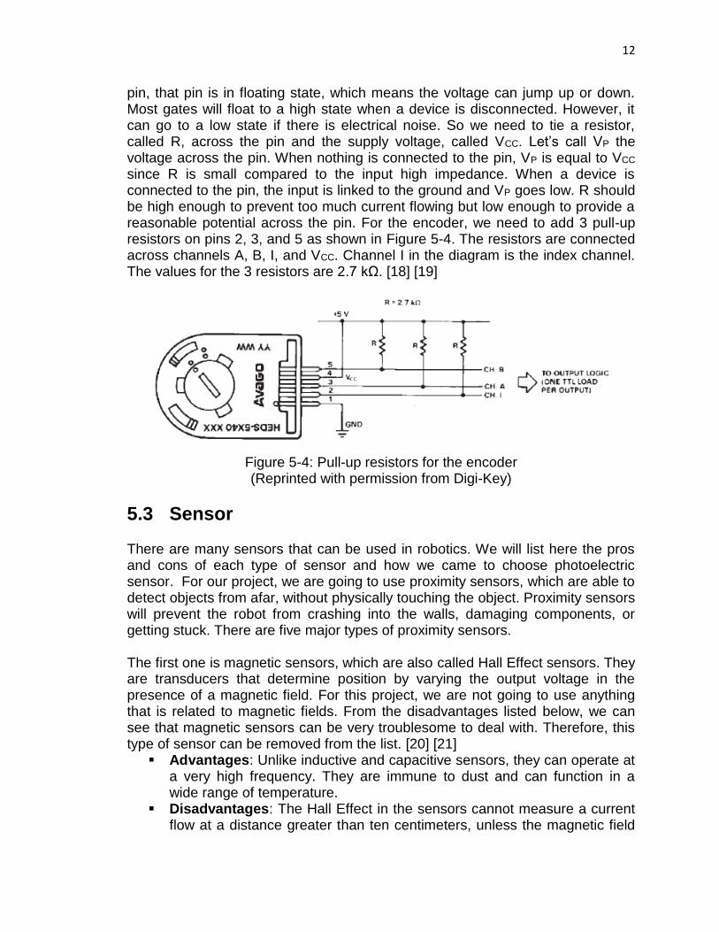
Figure 5-4 shows an Avago HEDS-5540#I12 encoder diagram of pull-up resistors. The pull-up resistors are used in logic circuits to ensure that inputs settle at a desirable logic levels in case external devices are disconnected or high impedance is present. Their job is to set a default value at a high state. The input to the logic gates has very high impedance. If nothing is connected to the
12
pin, that pin is in floating state, which means the voltage can jump up or down. Most gates will float to a high state when a device is disconnected. However, it can go to a low state if there is electrical noise. So we need to tie a resistor, called R, across the pin and the supply voltage, called VCC. Let’s call VP the voltage across the pin. When nothing is connected to the pin, VP is equal to VCC since R is small compared to the input high impedance. When a device is connected to the pin, the input is linked to the ground and VP goes low. R should be high enough to prevent too much current flowing but low enough to provide a reasonable potential across the pin. For the encoder, we need to add 3 pull-up resistors on pins 2, 3, and 5 as shown in Figure 5-4. The resistors are connected across channels A, B, I, and VCC. Channel I in the diagram is the index channel. The values for the 3 resistors are 2.7 kΩ. [18] [19]
Figure 5-4: Pull-up resistors for the encoder (Reprinted with permission from Digi-Key)
5.3 Sensor There are many sensors that can be used in robotics. We will list here the pros and cons of each type of sensor and how we came to choose photoelectric sensor. For our project, we are going to use proximity sensors, which are able to detect objects from afar, without physically touching the object. Proximity sensors will prevent the robot from crashing into the walls, damaging components, or getting stuck. There are five major types of proximity sensors. The first one is magnetic sensors, which are also called Hall Effect sensors. They are transducers that determine position by varying the output voltage in the presence of a magnetic field. For this project, we are not going to use anything that is related to magnetic fields. From the disadvantages listed below, we can see that magnetic sensors can be very troublesome to deal with. Therefore, this type of sensor can be removed from the list. [20] [21]
Advantages: Unlike inductive and capacitive sensors, they can operate at a very high frequency. They are immune to dust and can function in a wide range of temperature.
Disadvantages: The Hall Effect in the sensors cannot measure a current flow at a distance greater than ten centimeters, unless the magnetic field
13
is big enough. External magnetic field from other devices can also interfere with the sensors. Temperature also affects the sensitivity of the sensors by changing the electrical resistance and the mobility of the carriers. Even when the magnetic field is absent, the output voltage still produces a small voltage, called the offset voltage, which is caused when the object is made from a non-uniform material.
The second type is capacitive sensors. They detect anything that is conductive or has a dielectric different from the air. They can be used to detect both metallic and non-metallic objects. The walls of the maze will be made of wood or a non-metallic material; so capacitive sensors could be used. However, after considering the cons, we decide to look for a better sensor. [22]
Advantages: They are inexpensive, fairly stable, do not take long to respond, and have low power consumption.
Disadvantages: Capacitive sensors can be affected by temperature and humidity. They can be accidentally triggered by dust if kept unclean. They are sensitive to noise and not as accurate as inductive sensors. Their measurement is not linear. They can be difficult to design.
The third type is inductive sensors. They have a coil inside that can generate a magnetic field to detect metallic object. We are not going to use any metallic object in our maze construction. Therefore, this type is eliminated as well. [23]
Advantages: They are pretty accurate, have high switching rate, and can work in harsh environment.
Disadvantages: Unlike capacitive sensors, they cannot detect non-metallic object. Their operating range is also limited.
The fourth type is ultrasonic sensors. They emit high frequency sound waves, which bounce off objects and travel back to the sensor. The sensors calculate the distance by measuring the time it takes for the waves to return. They cost around 20 to 30 dollars, which are pretty cheap but we can always find other cheaper sensors that have less problems. [24]
Advantages: Ultrasonic sensors work great even in rain, dusty, or adverse environment. They are not affected by colors and can detect both solid and liquid forms.
Disadvantages: They cannot detect objects that are too close because the time it takes to travel back is too short for the electronics to respond. If the objects are too far, the sound can grow weak with distance. Air motions such as winds can falsely trigger the sensors. The density and the material of the objects can distort sensor readings. If the walls of the maze are made of wood, which doesn’t have uniform density, it can mess up the readings. The sensors consume around 100 milliamps when not in use but it can jump to several amps when used.
The last one is photoelectric sensors. The emitter produces either invisible infrared beam or visible LED light. The detector uses a method called

14
triangulation, which determines the distance by measuring the reflected angles. Farther object has smaller reflected angle. Likewise, closer object has larger reflected angle. The sensor’s detector has a charge-coupled device (CCD) array that reads the reflected angle and outputs an analog value in form of voltage. The voltage in turn serves as an input to the microcontroller. We chose this type of sensors because of their advantages. Like other sensors, they have downsides as well but it’s easy to fix these problems. [25]
Advantages: They are cheap, only cost around 10 dollars to 20 dollars. They are easy to set up, have low power consumption and can work quite well with sunlight if we are using Sharp brand.
Disadvantages: They cannot detect close objects so we will put the sensors in the back of the robot so that the front is located outside of the minimum sensing range. Another problem is cross interference, which occurs when two or more sensors are placed too close to each other. The signal emitted by one sensor can be read by another sensor. To solve this problem, we can position the sensors on top of each other, instead of side by side.
5.3.1 Photoelectric Sensor Photoelectric sensors work in three major modes: through-beam, retro-reflective, and diffuse-reflective, as shown in Figures 5-5, 5-6, and 5-7. For our project, we are going to use diffuse-reflective mode because we don’t have to set up emitter and detector separately. According to Figure 5-8 [26], even though diffuse-reflective mode is less accurate and has shortest sensing distance, that shouldn’t pose any problem. The walls of the maze should be close enough to the robot so that the beam will be able to reach.
Figure 5-5: Through-beam mode
Figure 5-6: Diffuse-reflective mode

15
Figure 5-7: Retro-reflective mode
Modes Advantages Disadvantages
Through-beam Longest sensing distance Most accurate Very reliable
Costly, require 2 components because emitter and detector are separate The installation could be difficult because the emitter has to be within the detection range of the receiver
Retro-reflective
Slightly less expensive than through-beam Longer range than diffuse-reflective Very reliable
Slightly less accurate than through-beam Slightly more expensive than diffuse-reflective Must install 2 components, sensor and reflector Dust on the reflector can affect performance
Diffuse-reflective
Emitter and detector are in one component, only install once Cheaper than through-beam and retro-reflective
More setup time involved Less accurate than through-beam and retro-reflective Shortest sensing distance
Figure 5-8: Pros and cons of sensor operation modes
5.4 Microcontroller The microcontroller is the brain of the entire system; without it instructions cannot be executed, algorithms cannot be implemented, data cannot be read and interpreted and tasks cannot be completed. There are many factors that must be considered when choosing a microcontroller, such as: the performance of the microcontroller (i.e. the processor speed, memory capacity, etc.); power consumption; number of analog to digital converters for sensors; output ports for

16
motors, communication and other necessary peripherals. Also, as with any real project, the cost of the MCU must be strongly considered. Figure 5-9 to Figure 5-15 show the analysis of some of the microcontrollers that were researched followed by the final decision with an explanation for the chosen microcontroller. [27] [28] [29] [30] [31] [32]
Raspberry Pi B+: $40
Pros Cons
High Quality Processor
Fast Clock time (700 MHz)
Programmable in multiple languages (C, Python, C++, etc.)
Easy to add expansion peripherals
High Power Consumption (5V at 2A)
Geared toward audio/visual I/O
Requires knowledge of Linux based systems
No on board A/D pins for sensor input
Figure 5-9: Pros and cons of Raspberry Pi B+
BeagleBone Black: $55
Pros Cons
High Storage Capacity- 512 MB DDR3 RAM, 4GB 8-bit eMMC on-board flash storage
Fast Processor- 1GHz ARM Cortex
Full Linux System on-board
Floating Point Capability
Two 32 Bit MCU
Wide array of Software Compatibility- Android, Debian, etc.
Includes native IDE and Script library
ON Board A/D converter
Must have knowledge of Linux based systems
High Power Consumption- 5V @ 210-460 mA
Most likely more advanced hardware than needed for this project
Also geared towards Audio Video outputs which is unnecessary
Figure 5-10: Pros and cons of BeagleBone Black

17
BASIC Stamp 2: $49
Pros Cons
Low Power- 5-5.5 VDC @ 23 mA
A/D converter for sensor I/O
Small Board Size
Native IDE
Programmable in C, C++, Arduino type language (PBASIC)
Slower Clock- 20MHz
Somewhat higher price
Native RF Communication Peripherals are somewhat expensive
Small Memory- 32 Byte RAM, 2kB EEPROM
Figure 5-11: Pros and cons of BASIC Stamp 2
PIC- Droids SAS MuIn - Multi Interface Board: $35
Pros Cons
Moderate Sized Memory- 12 Kbytes on-chip Flash program, 512 bytes on-chip data RAM
Moderate Power Consumption- 3.3 V @ 250 mA
Programmable in C
Included, optimized compiler for native instruction set
Capable of handling up to 12 sensor inputs to ADC
multiple PWM for outputs such as motors
No native IDE
Price is somewhat high compared to others
Figure 5-12: Pros and cons of PIC- Droids SAS MuIn
Wiring S Microcontroller: $26.99
Pros Cons
High Memory Capacity- 62 kB of Flash, 2kB SRAM, 4 kB of EEPROM
Plenty A/D pins for sensors- 8
PWM outputs- 6 on board, more than needed for motors
High operating voltage- 7.5-12 VDC
Slow oscillator- 16 MHz
Figure 5-13: Pros and cons of Wiring S

18
TI MSP430 family: $12-$24
Pros Cons
Inexpensive
Online E2E community
Energia- Arduino based IDE
All group members are familiar with Texas Instruments hardware
Low Power Consumption- 1.8-3.6 V @ 200 μA
Differential ADC – connect directly to sensors and limit interference
For prototyping, most peripherals need to be added
Figure 5-14: Pros and cons of TI MSP430
TI Tiva C Series: $12
Pros Cons
Inexpensive
Online E2E community
Energia- Arduino based IDE
All group members are familiar with Texas Instruments hardware
Differential ADC – connect directly to sensors and limit interference
Boosterpacks for prototyping can be expensive
Figure 5-15: Pros and cons of TI Tiva C
After comparing all the models above as well as many others, the group has decided to use the MSP430 microcontroller family for this project. This decision was based on a number of factors. First, this project was originally thought of as something that would require low power. We need low power consumption for two reasons: to maximize the length of time that our robots can operate before needing to be recharged and also we need to minimize the amount of weight on the robots to reduce the stress on the wheel motors and to minimize the size of the robots. Avoiding a bulky battery that carries a lot of weight and demands a lot of board space is paramount to making our design effective. Secondly, the team wanted a microcontroller that has as many native peripherals as possible. This is because we thought it would be easier to interface the necessary communication hardware and thing s of the like if they were manufactured by the same company. Texas Instruments has a booster pack for the Sub GHz hardware that is needed for robot to robot communication.
19
Obviously some of the other microcontrollers have some of these same characteristics as those described above. The reason that the MSP430 microcontroller was ultimately chosen above all the others researched was for a very simple reason, all three members are familiar with its technology and we have multiple development boards to prototype on. The team agreed that the design should be focused on the things we do not know versus what we do know. This all comes back to the idea that our senior design project will be a learning process in which the skills of all involved can be enhanced.
5.5 Power Supply Three types of battery are considered: nickel metal hydride (NiMH), nickel cadmium (NiCad), and lithium ion (Li-Ion). NiCad is cheaper than NiMH and has highest current output among the three types. NiCad takes around one to two hours to fully recharge. The battery needs to be fully discharged before recharging to prevent memory effect in which the battery holds less charge over time. NiMH battery is a newer technology of NiCad. It’s known to have limited memory effect and higher energy density than NiCad. NiMH battery has good current output and is more environmentally friendlier than NiCad. However, it takes around five to ten hours to fully recharge. Li-Ion is the most advanced technology among the three. It is environmentally friendly and has the same energy as NiMH battery but weighs less. Li-Ion has higher energy density than the other two. It has no memory effect. Nonetheless, Li-Ion may explode and cause fire if it’s not handled properly. Alkaline disposable batteries are readily available, commonly used, and cheap. However, they are heavy and have low power capacities. Since the robots might go through extensive maze-solving tests. It’s not desirable to use them since it can get expensive to constantly replace. The battery might also have trouble supplying large amounts of current in a short time. Rechargeable NiMH battery is available in 1.2 V per cell. Thus, the batteries are commonly sold in a multiple of 1.2 volt: 2.4 V 3.6 V 4.8 V and so on. Rechargeable Li-Ion single cell’s nominal value is 3.6 V However, some manufacturers mark their products as 3.7 V but there is no significant difference between the two. Li-Ion cells are combined to form 7.4 V 11.1 V and so on. [4] [33]
5.6 Voltage Regulator Switching regulator is favored over linear regulator because it has a much higher efficiency, typically 85 percent compared to linear regulator’s typical efficiency of 40 percent. Even the new linear low drop-out (LDO) regulators are still inefficient. Since linear regulator’s efficiency is low, it generates a lot of wasted energy in the form of heat which has to be dissipated by heat sink. In addition, it’s difficult to drive loads over 200 mA and reduces battery life. Switching regulator’s efficiency doesn’t depend on input voltage as much as linear regulator. However, switching regulator generally is more complicated to set up than linear regulator because it has more pins and requires more external components. [34]
20
Switching regulator is available in several varieties. The three varieties that are of interest and more applicable to the project are buck, boost, and buck/boost regulators. Among all the types, buck regulator is the most commonly used and often seen in robotic projects. The buck regulator requires the input voltage to be higher than the output voltage. As a consequence, battery’s power is wasted. A better alternative is the buck/boost regulator. This kind of regulator combines the principles of the buck and boost regulators. For a constant output voltage, the buck regulator would take over to reduce the input voltage if it’s too high and boost regulator would boost up the input voltage once it goes too low. Therefore, the buck/boost regulator would be ideal to be used with battery because the supply voltage may be lower or higher than the regulated output voltage. Since the team registered to participate in Texas Instruments’ Innovation Challenge, we would use the manufacturer’s products. TI offers less options for buck/boost converters compared to the buck converters. One downside of TI buck/boost converters is that they generally require more external components than buck converters. Buck regulator is also a good option since the input voltage is lower than the output voltage. As a result, the power supply is lighter than the one used for buck regulator since less number of battery cells is needed.
5.7 Communication Hardware Since the project involves multiple robots working to solve a maze together there must be a way for the robot tandem to share information. Adding this capability gives the project another dimension of complexity and can increase efficiency using the “two heads are better than one mentality” except in this case it is “two robots are better than one”. There are many different technologies in the market place that can enable two robots to transmit information back in forth. This project could, in theory, attach an extremely long wire to physically connect the two microcontrollers and use serial communication; however there is the strong possibility that the wires would get caught on a corner or end up not being long enough. For this reason the project will employ wireless communication to allow communication between the Twinbots. There is a multitude of wireless communication technologies in the market place. These include technologies such as: infrared, Bluetooth, 2.4 GHz RF, Sub GHz RF, Wi-Fi and more. When considering which technology to utilize we need to consider many different aspects that can affect the overall quality of performance. The most important thing that needs to be determined when evaluating a given communication technology is whether or not it can transmit information under the circumstances that our system will be designed for, if the technology cannot transmit information under the desired circumstances then it would obviously be a waste of time to use it. Another important factor is the range over which the given technology can operate. The distance over which information can be transmitted under the desired conditions must be determined to accurately compare different technologies. Another consideration which is

21
paramount to this project is the power consumption of each given technology. Since this project is being designed as a low power project, the communication technology must not consume a large amount of power or else it will drain the system and hinder overall performance. The amount of information that can be transmitted and how fast it can be transmitted must also be considered. This is not a primary concern for this project since the data that will be sent via wireless communication will be fairly small, maybe a few bytes at time, however, the design team must be sure that the whatever hardware we use based on the other primary concerns can handle our packet size. Lastly, as always the cost of the given hardware must be considered closely to fall in line with the other project constraint that the robots be low cost. Below is an analysis of the different possible technologies and their characteristics. Precedence will be given to the technologies that excel in the areas of importance mentioned in the preceding paragraph. After the analysis of these technologies will be the final decision on the technology to be employed and the basis on which that decision was made.
5.7.1 Infrared Communication Infrared communication is a very popular communication technology for many applications such as remote control, robotics, etc. Infrared communication has been used in applications such as remote effectively since around the 1950’s; it is an effective way to wirelessly transmit data. There are many aspects of infrared communication that can make it a suitable means of transferring data given the right conditions. It is a very low power option that generally requires no more than a couple of AA batteries. Since infrared is a very popular technology it is also well established and has existed in the market place for many years now. Due to this widespread market utilization it is also a very inexpensive technology and has many resources on the fundamentals of its operation. The data transfer rate of infrared is not as fast as some other technologies (around 4 MB per second), but that is fast enough for this project and therefore is not an appreciable problem. Unfortunately, infrared communication also has some serious drawbacks. Due to the high frequency with which infrared operates, about 100-214 THz for lo grange telecommunications, infrared cannot pass through solid objects such as walls or nay other solid material. This means that to effectively utilize infrared technology the receiver must be visible to the transmitter or the signal will be totally reflected and not be transmitted/ received at all. Another drawback of infrared is that it only works well over short distances, about ten meters. This is a problem for this project because it is supposed to be designed to work over a long range. The last notable drawback of IR is that only one pair of devices can connect. This would be a problem if this project wanted to employ more than two robots at the same time.

22
5.7.2 Bluetooth Bluetooth is another solution to utilize wireless communication. It is somewhat newer technology that has many advantages over infrared and other technologies. Bluetooth was invented I m1994 by Ericsson as an alternative for RS-232 serial communication. Bluetooth utilizes radio frequencies in the 2.45 GHz range to transmit data. The reason it has not been lumped into the 2.4 GHz section of this report is because of some key differences between the two that will be addressed later. As with any technology, Bluetooth has some positive attributes as well as some shortcomings. Bluetooth technology is actually an RF standard that employs a standard protocol as well. This means that any device operating on Bluetooth technology will operate in a specific frequency range and send information in a uniform format. This leads to one of the biggest benefits to using Bluetooth technology, automatic connectivity. If any two Bluetooth devices are within the operating range and they are both enabled they will connect and transmit data automatically. This adds a level of convenience for the user since they do not have to worry about formatting how they transmit data or whether or not they are connected. Bluetooth technology also has the advantage of being a low power transmission option for wireless communication; it transmits about 1 mW per transmission. This helps save on power consumption which can lead to savings in space due to less of a need for a large battery. This is obviously advantageous if larger packets of information must be sent. Also, Bluetooth can incorporate multiple devices at once due to its “frequency hopping” which allows up to 79 devices on as many different frequencies communicate with one another. This would be advantageous for this project if multiple robots were to be created and added in the future. Although there are many advantages to using Bluetooth technology, there are also some disadvantages that must be taken into account. While Bluetooth is a low power and easy to use technology it also has the disadvantage of only being able to transmit data over a range of a few meters. This would not be a huge problem except that, as mentioned before, this project is supposed to be designed to operate over a substantial distance, ideally much farther than ten meters. Bluetooth is also capable of fast data transfer, up to 3 megabits per second which is slower than infrared but still fast enough for the application of this project.
5.7.3 RF Communication Radio frequency (RF) communication is the most popular form of communication in modern technology today; Bluetooth is actually a specialized form of RF communication designed to operate over short distances. Most RF communication technologies are designed to operate over greater distances than technologies like Bluetooth or Infrared with ranges of up to a few kilometers. RF

23
communication technologies are generally classified by the frequency with which they transmit information; the two that will be addressed here are two frequencies in the ISM (industrial, scientific, medical) frequency band, 2.4 GHz and sub-GHz technology. Instead of separating them into two different categories they will be compared side by side due to many commonalities in their operation as well as to highlight some of their differences. 5.7.3.1 2.4 GHz 2.4 GHZ technology is the most popular frequency in most wireless internet routers today; it has been the chosen frequency in the ISM band for some time due to the IEEE standards. This frequency has a balance between range and penetrability. If allowed to transmit through free space it has a range that is higher than a 900 MHZ system and also allows for smaller antennas due to the shorter wavelength of a 2.4 GHz RF signal. Unfortunately signals are not transmitted in free space so there will be greater transmission loss for a 2.4 GHz signal if obstructions are encountered such as walls and other solid objects. Another important feature of 2.4 GHz technology compared to 900 MHz technology is the data rate associated with each; 2.4 GHz technology allow for higher data transfer rates. 5.7.3.2 Sub GHz (900 MHz) Sub GHz technology has become increasingly popular over the last few years for a number of reasons. It is still a part of the unlicensed ISM band making it suitable for industrial applications. It has some of the same advantages of 2.4 GHz technology with some vast improvements. While 2.4 GHz experiences better range in free space transmission, sub GHz technology is vastly superior in transmission through environments where obstructions are encountered resulting in an overall better range for sub GHz transmission. This is due to a number of factors, one of which is path loss. Path loss is a mathematical model describing how much of a signal is lost over a certain distance for a certain wavelength [35]. It is given as:
Path Loss(dB) = 20 ∗ log10 (4∗π∗d
λ) (5-4)
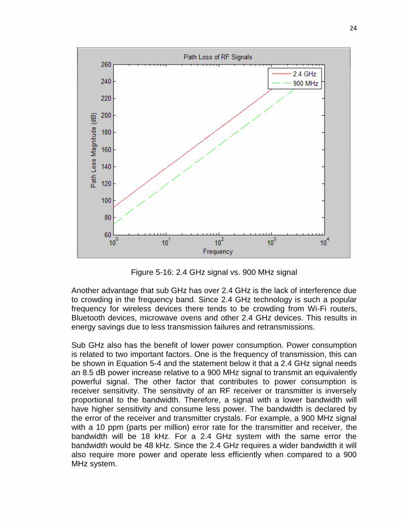
Where d is the distance and λ is the wavelength of the transmitted signal. Since wavelength is inversely proportional to frequency it can be seen that a 90 MHz signal would have far superior range compared to a 2.4 GHz signal. As a matter of fact a 900 MHz signal would have approximately 2.67X increase in range compared to a 2.4 GHz signal. A 2.4 GHz device would have to increase its power by nearly 8.5 dB to match the range of a 900 MHz signal operating at lower power. A graph comparing the path loss of a 2.4 GHz signal to a 900 MHz signal is shown below in Figure 5-16.
24
Figure 5-16: 2.4 GHz signal vs. 900 MHz signal Another advantage that sub GHz has over 2.4 GHz is the lack of interference due to crowding in the frequency band. Since 2.4 GHz technology is such a popular frequency for wireless devices there tends to be crowding from Wi-Fi routers, Bluetooth devices, microwave ovens and other 2.4 GHz devices. This results in energy savings due to less transmission failures and retransmissions. Sub GHz also has the benefit of lower power consumption. Power consumption is related to two important factors. One is the frequency of transmission, this can be shown in Equation 5-4 and the statement below it that a 2.4 GHz signal needs an 8.5 dB power increase relative to a 900 MHz signal to transmit an equivalently powerful signal. The other factor that contributes to power consumption is receiver sensitivity. The sensitivity of an RF receiver or transmitter is inversely proportional to the bandwidth. Therefore, a signal with a lower bandwidth will have higher sensitivity and consume less power. The bandwidth is declared by the error of the receiver and transmitter crystals. For example, a 900 MHz signal with a 10 ppm (parts per million) error rate for the transmitter and receiver, the bandwidth will be 18 kHz. For a 2.4 GHz system with the same error the bandwidth would be 48 kHz. Since the 2.4 GHz requires a wider bandwidth it will also require more power and operate less efficiently when compared to a 900 MHz system.

25
5.7.4 Decision Before making any final decisions on which communication technology we need to review the important parameters that will influence which technology is utilized. First and foremost, the technology must be able to physically transmit the required information successfully. Since the Twinbots will be operating within a maze, which inherently have obstructions, the project cannot use any technology that requires “line-of-sight” communication. For this reason infrared communication cannot be used in the project. Secondly, while this project is to be demonstrated within a maze that does not cover a very large area, there is a scalability factor that is being considered. Therefore, the communication method must be able to transmit over large distances, ideally over 500 meters. Figure 5-17 shows the ranges of all technologies being considered, except infrared since it has already been eliminated.
Figure 5-17: Range comparison of different communication technologies
Based on the data in Figure 5-17, Bluetooth must be eliminated from consideration due to its lack of range capabilities. Since all of these communication technologies are of comparable cost, the last thing that will be considered is power consumption. As mentioned earlier, sub GHz technology, specifically 900 MHz in this case, has a considerably lower path los than 2.4 GHz technology. Due to this fact it can be shown that to reach equivalent distances of transmission, a 2.4 GHz signal would need to be transmitted with about an additional 8.5 dB of power than a 900 MHz signal would. It has been clearly shown that this project is intended to be as power efficient as possible; for this reason the project will utilize sub GHz technology to allow for wireless communication between the Twinbots. This decision was reached without specifically addressing the difference in data rate of Bluetooth, 2.4 GHz, and sub
10 500 12000
200
400
600
800
1000
1200
1400
Bluetooth 2.4 GHz 900 MHz
Typical Range (meters)
Communication Technology
Range Comparison for Transmission of Possible Communication Technologies

26
GHz technologies due to the fact that the Twinbots will be sending small packets of information therefore making the data rate a secondary concern to range and power efficiency. After researching sub GHz RF modules the team has decided to utilize the Anaren A110LR09A00GM module [36]. This module is very suitable for this project. It is supported n the Texas Instruments e2e community and is programmable in the Energia IDE. This module is also low cost, only about $25-35 for a pair of modules. Another aspect that is very appealing is that it is a very small module that will not take up a lot of board space; its dimensions are only 9x16x2.5mm. This module operates at 915 MHz and has a baud rate of 1.2k which will be enough for the application it is intended for. It also is power efficient consuming only 200 nA of current in sleep mode and 15 mA in active mode. It is simple to power and requires no additional voltage regulation since it can be supplied at the same Vcc as the microcontroller. Due to its lower power consumption and inexpensiveness it will be a suitable choice for this project.
5.7.5 CC110L Transceiver The actual operation of the Anaren A110LR09A is controlled by the transceiver that it uses. The transceiver is a CC110L RF transceiver made by Texas Instruments; it is a twenty-four pin device that is capable of operating at the 915 MHz frequency that the design team has chosen. This device has very specific operating characteristics that allow it to operate efficiently and consume a low amount of power. One of the most appealing features of this transceiver is the fact that it is designed to be power efficient. The transceiver operates at Vcc of the microcontroller (for this project it will be 3.3V) while drawing low current. In sleep mode it draws about 200 nA, about 15 mA in receive mode, and about 30 mA in transmit mode. Since this project will operate the transceiver in sleep mode for a majority of the execution time the communication module will likely consume negligible power compared to other components until it needs to transmit or receive. One of things that contributes to this power efficiency can be explained from the bandwidth discussion earlier. This transceiver has a bandwidth of about 26 MHz which allows for a higher efficiency component. Since this module will be operating in sleep mode for a majority of its operation the wake up time of the transceiver is also important. The CC110L transceiver has a typical wakeup time of 150 μS which is very fast and allows for quick transmission of signals without having to pause for a long period of time allowing the module to power up into its active modes. Due to the fact that this project is supposed to be designed to be scalable for operating over large ranges, noise levels of the transceivers must be accounted for to ensure low error rates in transmission. Luckily the CC110L transceiver has a very low noise floor, typically -92dBc/Hz.

27
One of the key features of the CC110L transceiver is that it can be programmed and optimized for specific applications. Based on the needs of its user the transceiver can be optimized for applications where it will be receiving and transmitting constantly, operating in standby frequently as well as for operations at different sub GHz ISM frequencies. This is all done using the SPI (Serial Peripheral Interface). Some of the key features that can be individually optimized using the SPI are shown below. • Power-down / power up mode • Crystal oscillator power-up / power-down • Receive / transmit mode • Carrier frequency / RF channel • Data rate • Modulation format • RX channel filter bandwidth • RF output power • Data buffering with separate 64-byte RX and TX FIFOs Some of the key features that relate to this project specifically would naturally be the data rate and the RF output power. Since this project must maintain a conscious effort to minimize power consumption while maintain performance at all times these two parameters must be closely examined to ensure that optimal power and performance are reached. The power-down/ power-up mode must also be optimized as well as receive and transmit modes. The operating frequency has been engrained into the Anaren module to be a 915 MHz module so that cannot be modified. A state diagram from the CC110L data sheet explains the individual operating/ power consumption of individual operating modes. It is a useful tool for understanding how the CC110L module operates. The state diagram is somewhat complicated however; the main thing to take from is that the CC110L transceiver does not waste much power by staying in operation modes during unnecessary times. Rather it seeks to enter idle mode or sleep mode every time it is not sending or receiving data, this is the key reason it was chosen for this project. Another benefit to using the Anaren Air module is that it takes care of a lot of RF design issues that would require more background in the RF field. This includes impedance matching techniques that ensure that the transmit amplifier is loaded correctly to achieve optimal output power. The Anaren module also includes filtering into its design that save the design team time on ensuring that false signals are not transmitted and ensures compliance with regulatory standards regarding “intentional radiator” rules. One of the other huge advantages that Anaren module provides is an on chip antenna that was designed with all of the impedance matching and filtering that was mentioned before. This again removes the need for RF engineering experience and ensures that an

28
omnidirectional radiation pattern is achieved which is optimal for this application. This module not only takes care of the RF design components that are being implemented but also takes care of its internal power management. The power management is mainly to allow for the transceiver to enter different operating modes to improve power efficiency. This allows the user to only hook up one power supply pin that connects to all the power supply pins on the CC110L internal transceiver.
5.8 Integrated Development Environment (IDE) An important consideration for this project is how the hardware will be programmed to make decisions. To do this thee must be a way for the hardware to be programmed, tested and debugged as quickly and efficiently as possible. Ideally the project will be programmed using a language that allows for higher level algorithms to be implemented without having to focus on manipulating individual bits and registers. To accomplish this, the design team will be utilizing the Energia Integrated Development Environment. The decision to use the Energia Integrated Development Environment was based on a number of factors. One of the most important reasons the design team chose Energia is that it is designed to utilize the Arduino programming language and incorporates the plethora of libraries that can be implemented for this project. This IDE has libraries dedicated to everything that this project needs to implement. There are libraries that can drive motors taking care of the pulse width modulation (PWM) required to do so. There are also libraries to read sensor data which will be incredibly important to expediting the decision making process required to successfully implement the necessary algorithms to solve the mazes and increase the efficiency with which they can be solved. Another useful feature that is associated with the Energia IDE is that sketches can be imported into Code Composer Studio which also speeds up development time. The design team can develop the basic algorithm using the Arduino language and libraries initially and then it can be imported into Code Composer if more precise refinements are needed such as optimization of register and manipulation of individual bits that cannot be accomplished in Energia. The design team believes that using Energia in conjunction with Code Composer Studio will allow for the optimization of the teams collective programming and development skills.
5.9 Maze Solving Algorithms We are going to build a perfect maze, which is also called simply connected maze. It has no loops, no inaccessible areas, and has exactly one solution. The maze is three-dimensional. The cells are rectangular and intersect at right angles. The start and the exit will be placed at the outermost wall. To build the maze, we are going to add new walls to the maze by connecting one end of the
29
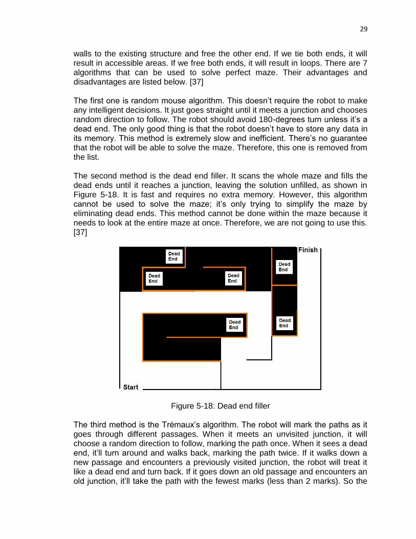
walls to the existing structure and free the other end. If we tie both ends, it will result in accessible areas. If we free both ends, it will result in loops. There are 7 algorithms that can be used to solve perfect maze. Their advantages and disadvantages are listed below. [37] The first one is random mouse algorithm. This doesn’t require the robot to make any intelligent decisions. It just goes straight until it meets a junction and chooses random direction to follow. The robot should avoid 180-degrees turn unless it’s a dead end. The only good thing is that the robot doesn’t have to store any data in its memory. This method is extremely slow and inefficient. There’s no guarantee that the robot will be able to solve the maze. Therefore, this one is removed from the list. The second method is the dead end filler. It scans the whole maze and fills the dead ends until it reaches a junction, leaving the solution unfilled, as shown in Figure 5-18. It is fast and requires no extra memory. However, this algorithm cannot be used to solve the maze; it’s only trying to simplify the maze by eliminating dead ends. This method cannot be done within the maze because it needs to look at the entire maze at once. Therefore, we are not going to use this. [37]
Figure 5-18: Dead end filler
The third method is the Trémaux’s algorithm. The robot will mark the paths as it goes through different passages. When it meets an unvisited junction, it will choose a random direction to follow, marking the path once. When it sees a dead end, it’ll turn around and walks back, marking the path twice. If it walks down a new passage and encounters a previously visited junction, the robot will treat it like a dead end and turn back. If it goes down an old passage and encounters an old junction, it’ll take the path with the fewest marks (less than 2 marks). So the

30
maze will have 3 types of passages: the unmarked paths that it hasn’t visited yet, the paths that are marked once, and the paths that are marked twice. The continuous path which is marked only once will be the solution, as shown in Figure 5-19. This is an efficient technique that prevents the robot from going in circle and visiting the same place more than twice. Trémaux’s algorithm is very similar to wall follower. In Figure 5-19, the robot is actually using the left-hand rule to find the exit. The only difference is that the robot needs to spray paint or use some sort of marking mechanism. Therefore, we are not going to use this. [37]
Figure 5-19: Trémaux’s algorithm
The fourth one is recursive backtracker. The general rule is to follow a random direction and only backtrack when reaching a dead end. The method considers 3 cases. If the robot hits a wall or revisits an old location, the function’s returned value is false. If the robot is at the finish line, the returned value is true. Otherwise, the recursive function guides the robot in one of the four directions. The robot assigns a value for the backtracking location so that it won’t have to pass through the same place again from a different direction. Every time it tries out new route, it’ll draw a new line. If the function returns false, the line is erased. The robot repeats this step until it draws a continuous line from the start to the finish. This method is fast but it uses memory proportional to the size of the maze. There are other better algorithms that use less memory. Therefore, we are not going to use this. [37] The fifth one is chain algorithm. For this method, we will need two wall-following robot. First, we have to locate the start and the end points. Then we draw a line between the two points, ignoring the walls. The first robot generally follows the line until it is blocked by a wall. Then it’ll try to go around. A second robot is sent out to follow the same wall in the opposite direction. If one of the robots intersects the line at a point closer to the exit, then the other robot will follow the
31
wall to get to that point. They keep following the line and repeat the previous step until the end is found. This method ensures a solution but uses quite a bit of memory. Therefore, we are not going to use this. [37] The sixth method is wall follower, also known as left-hand rule or right-hand rule. It is equivalent to a person placing one hand on the wall at all time and walks through the maze until he reaches the exit. This technique is also called the LSRB algorithm. L stands for left; S stands for straight; R stands for right; and B stands for turning around. Let’s say the robot uses the left-hand rule. Basically, the robot follows 4 conditions. Firstly, it should turn left whenever it can. Secondly, it should go straight if it cannot turn left. Thirdly, it should turn right if it can neither turn left nor go straight. Lastly, it should turn around if the previous 3 conditions are not met, which means it has encountered a dead end. To trace through the solution, we can also mark the passages like in the Trémaux’s algorithm. We choose this method because it is fast and requires no extra memory. Also, the robot will always find the exit if there is one. The downside to this is that the robot will keep going in a circle if the start or the end points are inside the maze. To solve this problem, we are going to put the entrance and the exit on the outer wall. Also, it may not offer the shortest way out if the maze has multiple solutions. Fortunately, our maze only has 1 solution so this should not pose any problem. [37] The last method is pledge algorithm. The robot will choose a default direction, either left or right, to always move in. The robot will keep track of the turns it makes. When it turns left, it’ll register -1. When it turns right, it’ll register +1. When the robot encounters a wall, it’ll follow that wall until all the turns sum up to 0. Then it keeps going straight. When it encounters another wall, it’ll resume its default direction. Figure 5-20 shows the passage taken by the right-hand robot using Pledge algorithm. A left turn is equivalent to a -90° and a right turn is equivalent to +90°. Let’s take a look at the first dead end that the robot encounters. The total number of turns sums up to 360. Even though the robot resumes its original direction (facing to the left), the sum is still not 0. Therefore, we have 2 conditions to satisfy. First, the robot has to face its original direction and the sum has to be 0. If both conditions are true, then the robot can go straight. This method is easier to implement than the wall following method. It only needs a counter that keeps track of all the turns. It doesn’t require all 3 sensors. It only requires the output from the front sensor and the sensor facing the wall. For the left-hand robot, the front sensor and the right sensor operate most of the time. When it goes straight, the front sensor is used to sense the obstacle ahead. After it turns left and follows the wall, the right sensor is used to find the next turn along the wall. On the opposite, the front sensor and the left sensor operate most of the time for the right-hand robot. Unlike wall follower, Pledge algorithm can find the exit on the outer wall if the start is in the middle of the maze. However, the opposite is not true. The robot cannot find the exit inside the maze if the start point is on the outer wall. It may visit the start point or some passages multiple times. If the maze is unsolvable, the number of turns will keep

32
increasing. We are not going to use this method because it is not compatible with our maze structure. [37]
Figure 5-20: Right-hand robot uses Pledge algorithm to find the exit
6 Initial Hardware Design
6.1 Voltage Regulation and Protection Circuit Sometimes motors would draw huge amount of current that battery source can’t handle. As a result, the whole system would experience a significant voltage drop, causing the microcontroller to reset and not working properly or sensor give bad readings. The solution to the problem is placing an electrolytic capacitor parallel to the battery pack. One of the main functions of capacitor is to store large energy quantity during idle periods and give up that energy when other components need it. The higher the capacitance, the more charge it can hold. Many capacitors are labeled with maximum voltage that the capacitors can handle without damaging them. It’s recommended to get capacitors that are rated at least twice the expected voltage drop across them to ensure that they don’t explode when fully charged. Since ceramic capacitor can lose about 50 percent of its capacitance at a rated voltage, it’s best to leave a large margin on the voltage rating. [38] [39] Capacitors are typically connected to the input and output of voltage regulator. The input capacitors filter out system noise prior to regulation. The output capacitors help the regulator deal with spikes created by the load. The regulator may oscillate at certain temperatures if the capacitors are not present. The large capacitors prevent low frequency interferences and keep the system powered when sudden current surges occur. Small capacitors prevent high frequency

33
disturbances from motors. They have low equivalent series resistance (ESR) that allow them to charge and discharge quickly. [40] [41] Under fault conditions such as short circuits and overload, fuse should be used to protect the motors from excessive current flowing from the battery. The fuse would heat up and blow, therefore, interrupting the current flow and preventing damage to the motors. Time-delay or slow-blow fuses are recommended for inductive loads such as motors. Fast-acting fuses are used for non-inductive loads. Fuse’s voltage rating indicates that the fuse can be used at all voltages not exceeding the rating. AC fuse can be used on a DC circuit but make sure that its voltage is rated at least twice that of the circuit. As a rule of thumb, the fuse’s current rating should be 125% of the full-load steady-state current. According to both the datasheets of Parallax continuous rotation servo and standard servo, the maximum current draw is 140 +/- 50 mA or 90 mA to 190 mA operated at a maximum DC voltage of 6 V To be safe, the maximum current should be aimed at 90 mA instead of 190 mA. To protect a single servo, a fuse would be selected with a current rating indicated in Equation 6-1. [42] [43]
90 mA x 1.25 = 112.5 mA or 112 mA (6-1) A rating slightly less than 112 mA is acceptable. We would use slow-blow fuses that have a current rating of 100 mA because they are the best ones that we can find so far. Since there are two motors, two fuses would be needed. Fuses can be connected in series or parallel. If there’re multiple power sources connected in series, then only one fuse is needed to connect in series to the sources and load, shown in Figure 6-1. If there’re more than one battery connected in parallel, then there must be one fuse for each battery in addition to one main fuse connected to a load, shown in Figure 6-2. The series configuration is obviously more advantageous than the parallel configuration because it requires less number of fuses.
Battery 1 Battery 2 Battery 3
Load
Figure 6-1: Series fuse configuration

34
LoadBattery 1 Battery 2 Battery 3
Fuse 2 Fuse 3 Fuse 4Fuse 1
Figure 6-2: Parallel fuse configuration
To protect the components in case the battery’s polarity is reversed, Schottky diode would be connected to the power supply to ensure that the current can flow only in the positive direction. Schottky diode is preferred over the normal pn-junction diode because it has a very low forward voltage drop, which means higher efficiency. A normal diode’s voltage drop usually ranges from 0.6 V to 1.7 V whereas a Schottky diode’s voltage drop is only between 0.15 V and 0.45 V. In addition, Schottky diode also has less voltage overshoot when device is turned on than the normal diode. The team would use a SB530-E3/54 Schottky diode manufactured by Vishay General Semiconductor because its forward voltage drop and reverse leakage current are relatively low. The forward current is high enough to be used with typical Li-Ion and NiMH batteries. High maximum reverse voltage ensures that the diode wouldn’t enter the breakdown mode when the battery’s polarity is reversed. [44] [45] Large capacitors that are fully charged after the robot is turned off can cause components to be accidently shorted and fried. A LED can be used to drain the capacitors and also serves as a status indicator. A dim LED might indicate that the circuit is low in power. The LED should be connected in series with a resistor to prevent the LED from frying. There’re tradeoffs in selecting the resistance. The higher the resistance, the more power it can drain but the LED’s brightness would decrease. Figure 6-3 explains how the LED is connected to its resistor as well as the power source and Schottky diode. Our team has acquired LEDs without cost from a workshop. Therefore, the LEDs’ manufacturer and part number are unknown. As a result, we don’t know the exact specifications for current and voltage. Typically, red LEDs are rated around 1.8 to 2.1 V and 10 to 20 mA. As a result, the LED’s average voltage and current should be around 2 V and 15 mA. The LED’s resistor R can be calculated by Equation 6-2. [46]
R = Vs – (0.48 + 2)
15 mA (6-2)

35
Figure 6-3: LED circuit
Figure 6-4 lists the calculated, rounded, and standard resistor values for given battery voltages. The standard resistor values are the actual ones that will be used in testing and prototyping. Because resistors normally are not available in rounded values, standard resistors with resistance close to the rounded value will be used instead. The third column in Figure 6-4 provides the resistor value by rounding up the calculated resistance. For a resistor value of 154.7 Ω, a 150 Ω standard resistor can be connected in series with one that is 4.7 Ω. This combination is close to the rounded value but requires two resistors instead of one. Another alternative is rounding up the calculated value to the next standard value which is 160 Ω. A 220 Ω standard resistor in series with two 10 Ω and 4.7 Ω standard resistors would make a perfect 234.7 Ω. However, this arrangement requires three resistors, which are undesirable because they would take space. It’s also harder to keep track during testing and prototyping as the number of resistors increase. Resistors’ value usually are coded by color bars. Having less resistors means the group would have less trouble of having to identify the value of each single resistor. Our team might use the next standard value of 235.7 Ω which is 240 Ω.
VS (V) Rcalculated (Ω) Rrounded (Ω) Rstandard (Ω)
3.7 81.33333 82 82
4.8 154.6667 154.7 150 and 4.7
160
6 234.6667 234.7 220, 10, and 4.7
240
Figure 6-4: LED’s resistor values
Voltage regulator is needed to regulate the voltage to microcontroller and sensor. Increasing or decreasing the input voltage even for a fraction of a second would result in the microcontroller resetting or sensor giving bad signals. Even though
IC
IL = 15 mA
IS

36
batteries are specified to operate at a nominal voltage, they are not always at the nominal value. A fully-charged can go higher than the nominal voltage. A drained one would drop significantly from the nominal value. Because microcontroller and sensor consume low current, the wasted power is not significant. As a result, either a linear regulator or switching regulator can be used. On the other hand, motors require a lot of current. In this case, switching regulator is ideal for the motors. [39] Multiple circuit protection and voltage regulation designs are considered. One design uses two power sources. A battery pack is used exclusively to power the motors. Another pack is used to power other electronics. The design divides the system into two main subsystems. One subsystem consists of one battery pack, motors, and fuses. The other subsystem includes the other battery pack, microcontroller, sensor, and voltage regulator. If one subsystem fails, then it would not affect the other subsystem. However, adding more battery packs means more space is occupied and adding load burden on the whole system, causing the motors to draw more current. Therefore, the design is unfit for our robot. Another design would have only one power source. There is one major drawback of this design, however. Since the whole system is interconnected, a component’s failure may affect the other components. For this design, several voltage regulators are taken into account including boost/buck, boost, and LDO (low drop-out) regulators. Before designing the circuit, it’s necessary to carefully study the datasheet of each component in order to understand the specifications. The most important rating that we need to look at is the voltage. Next, we take note of the current. Then, we need to calculate the sum of the maximum currents consumed by the electronic devices in the system. Finally, we have to determine how many and what type of battery cells are sufficient to power the devices. Figure 6-5 shows the voltage and current ratings for the listed devices. Many Li-Ion and NiMH batteries are more than able to provide 517 mA. Therefore, we should focus more on the voltage.
Device Voltage
(V) Typical
Voltage (V) Maximum current
(mA)
MSP430F5529 Microcontroller
1.8 – 3.6 3.3 < 100
Sharp IR Range Sensor 4.5 – 5.5 5 22
Parallax Servo 4 – 6 5 190 x 2 = 380
Red LED 2 15
Total: < 517
Figure 6-5: System’s overall current and voltage requirements

37
6.1.1 Boost Regulator Circuit Design Figure 6-6 shows a circuit design with a TI TPS61232 boost converter. TPS61232 is preferred over the TPS61230 and TPS61231 because it allows a 5 V fixed output voltage whereas the other two have adjustable outputs which require additional resistors to adjust the voltage. The converter is ideal for our project because its maximum efficiency is 96 percent. With an input ranging from 2.3 V to 5.5 V it’s able to regulate a fixed output voltage of 5 V that is required by the sensor and servos. The converter also delivers up to 2.1 A of current with a 5 V output and 3.3 V input. This current is more than enough to power the electronics in the system. The converter has additional built-in features including output over voltage and thermal shutdown protections, power good output, and power save mode for light load which typically consumes 1.5 uA. The converter is optimized for a one-cell Li-Ion battery, which is usually rated at 3.7 V. Either a single Li-Ion cell or three NiMH cells with a voltage of 3.6 V can be used. Based on Figure 6-4, the LED’s resistor should be 82 Ω for a power supply of about 3.7 V. C1, C2, C3, L, and R2 are required external components whose values are specified in the TPS6123x datasheet. They help to stabilize the regulator. The inductor and the output capacitor C3 serve as energy storage during conversion. Both the EN hysteresis program, marked by HYS and the power good, PG, pins can be left floating or unconnected if not used. At moderate or heavy load currents, the converter would operate at a 2 MHz frequency pulse width modulation (PWM). At light load current, it reduces the switching frequency and operates with pulse frequency modulation (PFM). For C1 and R2, standard 22 µF capacitor and 1 MΩ resistor will be used. C2 has a value of 10 nF, which is equivalent to 10,000 pF or 0.01 µF. A 10,000 pF is harder to find than a standard 0.01 µF capacitor. Thus, our team will use a 0.01 µF capacitor for C2. C3’s value can be achieved by connecting three 22 µF capacitors in parallel. The team will have to purchase 1 µH inductor. The battery drops 0.48 V across the Schottky diode, resulting in a 3.22 V at the converter’s input. A 3.22 V still safely remains in the converter’s specified input range. Since the microcontroller needs a 3.3 V, two regular diodes will be used. Each one has a voltage drop of 0.85 V totaling 1.7 V. The regulator’s 5 V output is then reduced to 3.3 V. Because the converter as well as other devices don’t have reverse voltage protection, Schottky diode is placed right after the battery to protect the rest of the circuit. DVCC1, AVCC1, P1.1, P1.2, and P6.4 are the pins on the MSP430F5529 microcontroller.

38
Figure 6-6: Boost converter circuit schematic
6.1.2 Buck/Boost Regulator Circuit Design If our team decides to use a buck/boost converter to regulate voltages, then a TI TPS63061 converter will be selected. Out of all the other TI buck/boost converters, it is one of the few that is able to regulate a fixed voltage of 5 V. Besides, its 93 percent efficiency is high. It can also accept input voltage range from 2.5 V to 12 V, making it ideal for low voltage supply. Nevertheless, it’s not advisable to have a converter’s input voltage at the exact minimum and maximum of the range since the input might deviate from the values. Going off the input range would result in a damaged converter or one that doesn’t regulate voltage at all. Therefore, the team decides to use a 4.8 V supply. VIN voltage then is 4.32 V due to the 0.48 V drop across the Schottky diode.
39
Unlike the TPS61232 boost converter, the TPS63061 has additional pins with special functions. The PS pin is used to enable/disable power save mode. A 1 is disabled and a 0 means enabled. During power save mode, the switching frequency and quiescent current is reduced to maintain high efficiency. Disabling the PS would set the switching frequency at a fixed rate. Connecting a clock signal at the PSY/SYNC pin would force the converter to synchronize to the clock’s frequency. To enable the EN pin, set it to 1. Otherwise, set it to 0. In many applications, the pin is tied to the supply voltage, which is on high. Hence, the pin is always enabled. To shut down the device, the EN can be connected to the ground. The battery and the load are disconnected during shutdown. The power good or PG indicates whether the output voltage is regulated properly. For the PG pin, setting to 1 means good, 0 means failure. The converter has additional features including overvoltage protection, over temperature protection, short circuit protection, under voltage lockout, and power save mode. Once the temperature goes beyond a threshold, the IC stops its operation. As the temperate decreased below the threshold, the device starts operating. The under voltage lockout functions by automatically starting the device only when the supply voltage on VIN is above a certain under voltage lockout threshold. If the supply voltage goes below the threshold, then the IC automatically enters shutdown mode. The overvoltage protection internally monitors the output voltage so that it doesn’t exceed critical values. There is no timer in the IC. As a result, the output voltage overshoot and current inrush occur at startup but the device keeps the current and overshoot at minimum. When the output voltage does not rise above 1.2 V the IC would assume a short circuit at the output and protect itself by keeping the current limit low, typically under 2 A. According to Figures 5 and 6 in the TPS6306X datasheet, the efficiency rises as the output current increases. The output current depends on the input current from the battery. As a result, the battery will be selected to have the current rating as high as possible. Figure 6-7 shows a circuit design with the TPS63061. C1, C2, C3, L, and R2 are the external components required by the TPS6306X datasheet. Larger capacitance of output capacitor C3 may be used without limit. A larger value would result in a lower output voltage ripple and output voltage drop during load transients. C2 is used to ensure that the internal control circuits are supplied with a stable low noise supply voltage. C2 can have a higher capacitance but it can’t exceed 0.22 µF. The input capacitor C1 is used to improve the transient and electromagnetic interference (EMI) behavior of the circuit. Since there is no standard capacitor value of 20 µF, two 10 µF capacitors will be connected in parallel to achieve 20 µF. C2, C3, L, and R2 selections will be the same as the ones used for TPS61232 boost converter. The TPS63061 converter can only output 800 mA, which is sufficient in powering other electronics. Even though Figure 6-7 shows a feedback pin on the converter, the TPS63061 may not be sold or sampled with such pin.

40
Figure 6-7: Buck/boost converter circuit schematic with motors subsystem at the converter’s output
Another design for TPS63061 buck/boost converter circuit would be separating the motors subsystem from the microcontroller and sensor subsystem and place it at the input of the voltage regulator, shown in Figure 6-8. The 4.8 V battery in the Figure 6-7 design is no longer able to support the motors because they require at least 4.8 V to operate but the voltage at the power pin of the motors is 4.32 V. For this reason, the 4.8 V battery is replaced by a 6 V battery. A 6 V is perfect because it falls in the range of input voltage for both the motor and the voltage regulator. The configuration in Figure 6-8 is more advantageous than the one in Figure 6-7 because the motors are not affected if the voltage regulator fails to regulate voltage.

41
Figure 6-8: Buck/boost converter circuit schematic with motors subsystem at the converter’s input
6.1.3 Linear Regulator Circuit Design Figure 6-9 shows a less complicated circuitry using a LM2937 LDO (low-dropout) linear regulator. This circuit is better than the circuits that use switching regulators since it has less number of components. Even though the LM2937 datasheet doesn’t specify the efficiency, the LDO regulator’s efficiency is expected to be lower than that of TPS61232 and TPS63061. Since the regulator can only output a maximum of 500 mA and its efficiency is low, it would be used to power the low-power devices including sensor and microcontroller. According

42
to Figure 6-5, the maximum current required for the microcontroller and sensor is only 122 mA. A 500 mA output is more than enough to supply the devices. For the components that require higher current such as motors, they will be directly connected to the battery instead of the regulator’s output. The LM2937-5 should be used because it has a fixed output voltage of 5 V. Unlike the TPS61232 and TPS63061 converters, the LM2937 has reverse battery protection. As a result, the Schottky diode would be connected to the fuses to protect the motors. The regulator’s reverse battery protection circuit automatically protects the sensor and microcontroller. Therefore, Schottky diode is not needed at the regulator’s input. Though the typical minimum dropout voltage is 0. 5 V, the input voltage should be at least 2 V higher than the output voltage for optimal performance. In other words, the input voltage is required to be at least 5.5 V but should be 7 V or higher. Because it’s harder to find a 5.5 V than a 6 V NiMH or Li-Ion battery, a 6 V battery will be used with the LM2937 regulator. The regulator’s quiescent current is typically 10 mA if the regulator is under full load and the input and output voltage difference is greater than 3 V. The LM2937 also has additional features including thermal shutdown, short circuit current limit, and overvoltage shutdown. The thermal shutdown circuitry is not intended to replace the heat sink. Running the IC at thermal shutdown is not advisable because the device’s reliability may be degraded as the junction temperature rises above the allowed absolute maximum junction temperature rating. In cases the output is shorted to ground or the load impedance is extremely low, the device would limit the current. If the LM2937 operates continuously at the current limit, then the IC would transition into thermal shutdown mode. Since our project wouldn’t not use any power supply that exceeds 26 V we have no need to be concerned about the overvoltage shutdown. The LM2937 lacks the under voltage lockout and enable functions. The output only tracks the input voltage until the input rises above 6 V where the device remains in linear operation. CIN is required if the regulator is located more than 3 inches from the power-supply-filter capacitors. COUT is required to stabilize the regulator. It has to be at least 10 µF and should be located as close as possible to the IC. The output capacitance may be increased without limit. Larger values would improve the transient response. The equivalent series resistance (ESR) for COUT must be at least 10 mΩ but must not exceed 3 Ω. If the ESR goes above its upper limit or below its lower limit, then loop instability or oscillation may occur.

43
Figure 6-9: LDO regulator circuit schematic
6.1.4 Microcontroller Interfaces Figure 6-10 shows the MSP430F5529 interfacing with other devices including sensor, motors, and radio module. All the pins of port 6 accept analog inputs then the ADC (analog-to-digital converter) converts them to digital signals. Because the sensor outputs analog data at its Vo port, the sensor’s Vo is connected to one of the analog pins of the microcontroller, which is port 6 pin 4, notated as P6.4. The microcontroller processes the sensor data which is then interpreted by a software program. All the pins of port 1 are general-purpose digital I/O pins. Therefore, the signal port from each motor is connected to one of the pins of port 1. One motor is connected to port 1 pin 1 and the other to port 1 pin 2. The pins accept command signal from the microcontroller and deliver it to the signal port of the motors. Once the command signal is received, the motors then generate mechanical energy to move the wheels. The microcontroller must be properly grounded. The analog ground supply, shown as AVSS1, and digital ground supply, shown as DVSS1 are tied to one common node, GND, which also serves as the ground for A110LR09A radio module as well as the motors, voltage converter, sensor device, and power supply. The analog power supply pin, notated as AVCC1, and digital power supply pin, notated as DVCC1 share 3.3 V, which is the typical Vcc specified in the MSP430F5529 datasheet. AVCC1 and

44
DVCC1 have the same voltage since the MSP430F5529 datasheet recommends that they are powered from the same source. However, the microcontroller can tolerate up to 0.3 V difference between the analog and digital power supplies during power up and operation. This 3.3 V is needed during program execution and flash programming. The voltage does not come directly from a power supply. Instead, the 3.3 V is the output of the voltage regulator connected to two diodes, as shown in Figure 6-6 to Figure 6-9. Not all pins of the A110LR09A radio module are connected to the microcontroller. The DNC (do not connect) as well as the NC (no connection) pins can be left floating since they are not in use. The DNC pins are internal connection used during assembly. The NC pins are not connected internally. Pin 8 and 17 are two primary ground pins. Either one can be grounded. The SCLK pin is a digital input that accepts SPI (Serial Peripheral Interface) bus clock signal. Pin 12 or _CSN pin is also a digital input that functions as SPI bus select. By default, it’s active low. The MISO/GDO1 pin is a digital output that delivers data from the radio when CSN is low. The pin acts as a general purpose I/O pin when CSN is high. MOSI is another digital input pin that accepts data into the radio. Since SCLK, MISO/GDO1, MOSI, and _CSN are digital pins, they are tied to the microcontroller’s digital P1.3 to P1.6 pins. VDD is the power supply pin which requires a supply voltage ranging from 1.8 V to 3.6 V. Since 3.3 V falls in this range, it’s convenient to connect the VDD to the 3.3 V. The A110LR09A datasheet recommends to disconnect analog pins 7 and 15 except in noisy environment in which they help reduce the noise on the modules internal VDD. GDO0 and GDO2 are digital I/O general-purpose ports. GDO0 can also act as an analog output. The CC110L transceiver on the A110LR09A radio module has internal voltage regulators that are unseen to the end user; however some of these do require coupling capacitors, fortunately the module supplies the internal voltage regulation required for safe operation as long as the module is connected to a power supply within the maximum and minimum values. There is a possibility that excessive noise on the power supply line can disrupt the transceiver. This can cause degradation in the wireless link which results in reduced range. The Anaren Air module has a solution to minimize the noise from the power supply. There is a decoupling pin that includes a decoupling capacitance on pin 7 (Vdcoup1) which can filter out unwanted noise from the power supply. In some cases this is not necessary however if the noise exceeds 10 mVpp then this decoupling would be the first option to eliminate noise. This is mentioned because there is a possibility that excessive noise will be encountered if switching regulators are needed close to the module since these can create noisy environments. If the noise level is in excess of 120 mVpp then additional steps will be taken to eliminate noise such as these methods suggested by the Anaren user manual:
1. Add more decoupling capacitance to pin 7 (Vdcoup1) 2. Include more filtering in the supply line

45
3. Add a low drop-out voltage regulator in the supply line
The SPI is the same as the one that was covered in the discussion about the CC110L transceiver and the power pin consists of nothing more than one supply pin and ground. In total, this means that only five pins must be connected between the microcontroller and the Anaren module which greatly simplifies the design. It can also be seen that a 27 MHz oscillation crystal is included in the design once again simplifying the design team’s design. The pullup resistor is at pin 63 on the MSP430F5529 MCU. The pullup resistor is used as a reference to invoke the default bootstrap loader after a BOR (Brownout Reset). Therefore, unless the application is invoking the BSL, it is important to keep PUR pulled low after a BOR reset, even if the BSL or USB is never used. To do this a recommended value of 1MΩ is used at this pin connected to ground. This ensures that the PUR is not unintentionally pulled high under normal operation.
Figure 6-10: MSP430F5529 microcontroller interface

46
6.1.5 Sensor Connection We’ll use a by-pass capacitor of 10 µF or more between the supply voltage and the ground to stabilize the power supply and filter out AC noise, as shown in Figure 6-11. We will need a cable to connect the 3 terminals of the sensor to the microcontroller. The cable usually has 3 colors: red, yellow, and black. The black head is connected to GND, which is the ground. The red head is connected to VCC, which is the supply voltage. The yellow head is connected to VO, which is the output voltage. The other side of the cable is connected to MSP430F5529 launchpad. The black end is connected to GND pin. The red end is connected to 5V pin. The yellow end is connected to P6, which is the pin for analog input. [47]
Figure 6-11: 10µF capacitor is added to stabilize the power supply (Reprinted with permission from Digi-Key)
6.2 System Integration Figure 6-12 is a block diagram of the whole system of each robot. The only command signal comes from the microcontroller to the motors to control the wheels’ movement. The two data signals in the system are the sensor and SPI data. Unlike other interfaces, the interface between the microcontroller and radio module is bidirectional. Data can flow the microcontroller to the radio module and vice versa. The system can be divided into different subsystems. One subsystem consists of the microcontroller and its interfaces. This subsystem is the central control and processing unit which acts as the decision-making brain of the system. Another subsystem includes the voltage regulator as well as its stabilizing components. It manages and maintains power. Finally, another subsystem comprises of the wheels, motors, and fuses. This subsystem is

47
responsible for moving the robot. Figure 6-6 to Figure 6-10 would go more into details of the whole system.
Microcontroller
Battery Pack
Left Motor Right MotorSwitching
Regulator
Sensor Radio Module
Rig
ht W
heel
Le
ft Wh
eel
Resistors
Capacitors
LED
Schottky
DiodeFuse
Diode
Inductor
5 V
Sensor Signal SPI
PWM SignalPWM Signal
5 V 5 V
3.3 V
3.3 V
Figure 6-12: System block diagram
Figure 6-13 shows the robot assembly. It’s best to keep the electronics further away from the motors which might cause electronic noise interference. Motors would be placed at the bottom of the chassis to drive the wheels. Electronics would be on the top away from the motors. The PCB is where the microcontroller, sensor, and protective circuit locate.

48
Figure 6-13: Robot assembly
7 Initial Software Design
7.1 Wall Following Algorithm We have 2 robots so one of them is going to use the left-hand rule. The other will use the right-hand rule. Initially, they follow the same path. At some point, they’ll take different route at a junction. The robot that finds the exit first will send signal to the other robot, telling it to stop searching and exiting the maze via the solution passage. The robots will have to make 3 decisions:
Look for a junction
Identify the type of the junction
Make a turn
These 3 decisions are in the form of if-else statements, which run over and over again in a loop until the final destination is reached. We will need 3 sensors: one is on the left side of the robot, one is on the right, and one is in the front. The voltage remains high when there is no obstacle and low when there is obstacle. Let’s consider the paths that the robots may encounter. There are 9 possible cases shown below in Figure 7-1.
Motors Wheels
Chassis frame
Battery packs
Rear caster
PCB

49
Junction type
Robot action Left sensor’s voltage
Front sensor’s voltage
Right sensor’s voltage
Go straight and search for the next junction
Low
High
Low
Turn left
High
Low
Low
Turn right
Low
Low
High
Turn left or turn
right
High
Low
High
Go straight or
turn left
High
High
Low
Go straight or
turn right
Low
High
High
Go straight, turn left or turn right
High
High
High
Turn around at
dead end
Low
Low
Low
Exit the maze
High
High
High
Figure 7-1: Sensor outputs for different types of junctions
There are 3 bits so there are 23 possible combinations. However, we have a total of 9 cases in Figure 7-1. The robot yields the same sensor output when it encounters a four-way junction or an exit. Therefore, we need to develop two distinct conditions for these cases. If either the left or the right sensor does not

50
detect any wall in 5 seconds, we can assume the robot already found the exit. If not, the robot is still inside the maze. Every time the robot encounters a dead end, the paths to the dead end are erased and replaced by a letter, either B, L, R, or S. So far, we compile 8 possible dead ends that can be substituted, as shown in Figure 7-2. These rules can apply anywhere in the maze as long as the sequence of turns is the same. Every time the robot encounters a dead end, it will scan the last 3 characters to verify if the character sequence matches with the ones in the table. If it matches, the robot will replace the character sequence with a single letter. If we run into other types of dead ends in the future, we’ll update this table. We will run as many tests as possible to verify if the table holds true for all circumstances. [48]
Junction type Sequence of turns Substituting letter
LBR
B
RBL
B
LBS
R
RBS
L
SBL
R
RBR
S
LBL
S
SBR
L
Figure 7-2: All possible dead ends that can be substituted by a letter.
We’ll start solving a simple maze to show how we store different turns in memory. Initially, no memory is stored. Immediately after entering the entrance, the robot finds itself at a three-way intersection. It uses left-hand rule so it decides to go straight because it cannot turn left at junction 1. S is stored in memory. At junction 2, it cannot turn left so it goes straight again. Another S is recorded. At junction 3, it turns right because it cannot go any other way. R is stored. The robot runs into a dead end and turns around. So far, we have SSRB. It turns left at junction 3 to head back to junction 2. Now we have SSRBL. From

51
Figure 7-2, RBL can be substituted by B. So SSRBL becomes SSB. If the robot visits junction 3 again, it’ll turn around instead of turning right. The robot continues to turn left at junction 2 to head towards junction 4. Now we have SSBL. The robot learns that its previous decision at junction 2 was wrong because going straight leads to a dead end. Therefore, this path should be avoided. Next time, it should turn right at junction 2. From Figure 7-2, SBL is substituted by R. So SSBL becomes SR. In Figure 7-4, the passage is shown by the first arrow segment.
Figure 7-3: Junctions where the left-hand robot makes a decision
Figure 7-4: The passages taken by left-hand robot
The robot continues to go straight. It encounters junction 4. As always, it will turn left whenever possible. L is stored. Then it encounters junction 5 and turns left. Another L is recorded. It sees junction 6 and turns left. This L is saved as well.

52
So far, we have SRLLL. Now, the robot is at junction 7. It turns left again. L is stored. However, it encounters a dead end so it turns around and goes straight. Now we have SRLLLLBS. The robot learns that turning left at junction 7 will lead to a dead end. Next time, it should turn right instead. So it replaces LBS with R, as shown in Figure 7-2. SRLLLLBS becomes SRLLLR. The robot encounters another dead end so it turns around and turns left to exit junction 7. So far, we have SRLLLRBL. From Figure 7-2, RBL is substituted by B. So SRLLLRBL becomes SRLLLB. Next time when it gets to junction 7, the robot will turn around. It turns right at junctions 6 and 5 to head back to junction 4. Two Rs are recorded. It keeps going straight once it passes junction 4. Now we have SRLLLBRRS in memory. The robot learns that by turning left at junction 4 leads to 2 dead ends. Therefore, SRLLLBRRS will be replaced with SRR. In Figure 7-4, the passage is shown by the second arrow segment. The robot continues on, turning right at junction 8. R is saved in memory. It turns left at junction 9. L is stored. So far, we have SRRRL. It turns left again at junction 10. L is recorded. The robot turns left at junction 11. Again, L is stored. It gets to junction 12 and turns left. Another L is saved. So far, we have SRRRLLLL. Now, the robot is at junction 13. It makes a left, which is recorded, hits a dead end, and turns around. B is stored. It turns right, and turns left to exit junction 12. Now we have SRRRLLLLLBRL. From Figure 7-2, LBR is substituted by B. So SRRRLLLLLBRL becomes SRRRLLLLBL. From previous mistake, the robot learns to go straight instead of turning left at junction 12. From Figure 7-2, LBL is substituted by S. So SRRRLLLLBL becomes SRRRLLLS. In Figure 7-4, the passage is shown by the third arrow segment. The robot proceeds to junction 14. It turns left. L is stored. However, it hits the wall so it turns around and turns left to exit the maze. Now, we have SRRRLLLSLBL. To avoid the dead end, the robot should go straight instead of turning left at junction 14. LBL is substituted by S so SRRRLLLSLBL becomes SRRRLLLSS. In Figure 7-4, the passage is shown by the fourth arrow segment. So in conclusion, the robot stops at 14 junctions and runs into 5 dead ends to go through the maze. This solution is not very efficient. The right-hand method offers a better solution. Figure 7-5 shows the solution to this maze, for both left-hand rule and right-hand rule. The solution is the fastest route to the exit because it doesn’t consist of any dead ends.

53
Figure 7-5: This is the solution to the maze.
Figure 7-6 shows all the junctions where the right-hand robot will make its decisions. Figure 7-7 shows all the paths that the right-hand robot will go through. We can see that the right-hand rule is more efficient for this maze. The right-hand robot only needs to go through 11 junctions and runs into 2 dead ends while the left-hand robot has to go through 14 junctions, as shown in Figure 7-3. However, right-hand rule is not always better than left-hand rule. It depends on the structure of the maze. For the first run of the test, we turn both robots on at the same time and place them at the entrance. The right-hand robot is likely to exit the maze before the left-hand robot, given they travel at the same speed and their sensor response time is the same. After it leaves the maze, it sends the map of the solution to the other robot. The left-hand robot locates its current location in the maze and uses the solution to exit the maze. On the second run of the test, both robots should be able to exit the maze at the same time since both already knew the solution.
Figure 7-6: Junctions where the right-hand robot makes a decision

54
Figure 7-7: The passages taken by right-hand robot
7.2 Control System Like humans, the robot is very likely to make mistakes in its decision-making process. So we need a way to ensure that it responds the way we want. For an example, if we tell it to go straight, there’s no guarantee that it doesn’t wander off to the left or the right. So we need an error-correcting mechanism called control system. The most common control system used in robotics is the PID system. P stands for proportional, I stands for integral, and D stands for derivative. PID is a closed-loop control system that allows feedback from the output to the input. Initially, we identify a desirable output. Then we compare the actual output to the ideal value. If they differ, then there’s an error. The error is fed back to the input through a control equation, which produces a new output. Again, the new output is compared to the desirable value. This process repeats until we obtain the desirable value from the actual output. The control equation has 3 terms: P, I, and D. Each term has its own control constant. KP is the proportional constant; KI is the integral constant; and KD is the differential constant. Equation 7-1 below demonstrates this relationship:
z(t) = P + I + D (7-1) The error e(t), shown in Equation 7-2, is the difference between the desirable output r(t) and the measured output y(t):
e(t) = r(t) − y(t) (7-2) The proportional term, shown in Equation 7-3, is the product of the proportional constant and the current error:
P = KPe(t) (7-3)

55
The integral term, shown in Equation 7-4, is the product of the integral constant and the accumulation of past errors:
I = KI ∫ e(τ)dτt
0 (7-4)
The differential term, shown in Equation 7-5, is the product of the differential constant and the rate of change of errors:
D = KDde(t)
dt (7-5)
So the adjusted output sums up to Equation 7-6 [49]:
z(t) = KPe(t) + KI ∫ e(τ)dτt
0+ KD
de(t)
dt (7-6)
Our goal is to control the robot so that it goes straight. To do this, we need to ensure that the robot always maintain an equal distance on both sides. The desirable distance detected by left and right sensor is given by Equation 7-7:
desirable distance = path width−robot width
2 (7-7)
So the pseudocode for the control equation is something like this [50]: Control function (Ideal value, Measured value)
Error = Ideal value – Measured value I = I + Error D = Error – Previous error Output = KP * Error + KI * I + KD *D Previous error = Error Return The derivative of time, dt, is the difference between the current time and the last time of sensor input. The variable dt is not included in the pseudocode because dt is the same for every loop so it is treated like a constant. Therefore, KD/dt and KI*dt are just constants; KD/dt is just KD and KI*dt is just KI. We find KP, KI, KD, and ideal values through trials and errors. To find KP, we set KI and KD to 0. Then we increase or decrease KP accordingly and observe the controlled output. A big KP value will make the robot swerve and a small KP value makes the robot sluggish. A good KP value is the one that produces the most stable output. We do the same for the other two constants. We increase KI until we see a perceivable change in the robot and decrease KI until the robot doesn’t jerk left or right. KI is an accumulative term so we should change it by a very small amount each time. As for KD, we increase it until the robot stops wobbling. Our ultimate goal is a control model with quick response time and small overshoot.

56
To go forward in a straight line, the left and right motors must have the same angular speed. Supplying the same power to both motors doesn’t mean that they rotate at the same speed. First, we identify the ideal power for going straight. Then we apply that power to the left motor. We measured the rotational speed of the left motor and call it the ideal speed. The right motor has to match up with the second motor’s speed. Again, we call the control function above. The input parameters to the function are the ideal speed from the left motor and the measured speed from the right motor. Equation 7-8 [51] solves for the rotational speed ω, where T is the encoder’s period, measured by CPU timer:
ω =360°
T=
degrees
second (7-8)
The pseudocodes to maintain both motors at the same speed is given below. Loop
Desired speed = Right motor speed Measured speed = 360/timer Call control function (Desired speed, Measured speed)
Right Motor Power = Power + Output Jump to loop
7.3 Movement Control In this section, we are going to discuss how the microcontroller controls the motors based on sensor input. The sensors continuously scan the surrounding environment and feed their analog values into the microcontroller. The CPU processes the data and translates it into physical distance measured in centimeters. Once the robot hits a junction or a dead end, the CPU sends signal to the motors to steer the wheels. The wheels can be in 8 states, as listed below. We’ll discuss in detail the behaviors of the robot in each state.
Go forward Go backward Turn left Turn right Turn around Accelerate Decelerate Stop
When the robot goes straight, the voltage on the left and right sensors remains low while the front sensor remains high. To move forward, the microcontroller tells both motors to spin clockwise. When we turn on the robot at the entrance, we’ll place it right in the middle of path so that it can maintain an equal distance from both walls. Ideally, the robot should keep a distance of 4 cm or greater on both sides, as shown in Figure 7-8. In case the robot strays off course and leans towards one side, it will need to adjust itself. The motors can also accelerate since the robot is just searching for the next junction. To accelerate, more power
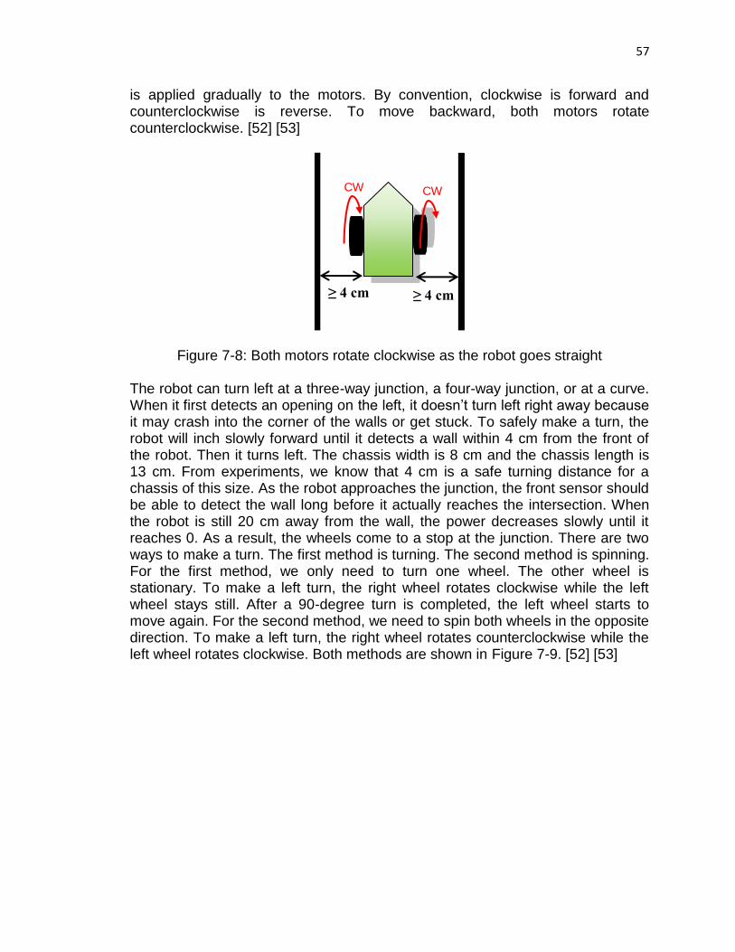
57
is applied gradually to the motors. By convention, clockwise is forward and counterclockwise is reverse. To move backward, both motors rotate counterclockwise. [52] [53]
Figure 7-8: Both motors rotate clockwise as the robot goes straight
The robot can turn left at a three-way junction, a four-way junction, or at a curve. When it first detects an opening on the left, it doesn’t turn left right away because it may crash into the corner of the walls or get stuck. To safely make a turn, the robot will inch slowly forward until it detects a wall within 4 cm from the front of the robot. Then it turns left. The chassis width is 8 cm and the chassis length is 13 cm. From experiments, we know that 4 cm is a safe turning distance for a chassis of this size. As the robot approaches the junction, the front sensor should be able to detect the wall long before it actually reaches the intersection. When the robot is still 20 cm away from the wall, the power decreases slowly until it reaches 0. As a result, the wheels come to a stop at the junction. There are two ways to make a turn. The first method is turning. The second method is spinning. For the first method, we only need to turn one wheel. The other wheel is stationary. To make a left turn, the right wheel rotates clockwise while the left wheel stays still. After a 90-degree turn is completed, the left wheel starts to move again. For the second method, we need to spin both wheels in the opposite direction. To make a left turn, the right wheel rotates counterclockwise while the left wheel rotates clockwise. Both methods are shown in Figure 7-9. [52] [53]
≥ 4 cm
≥ 4 cm
CW CW
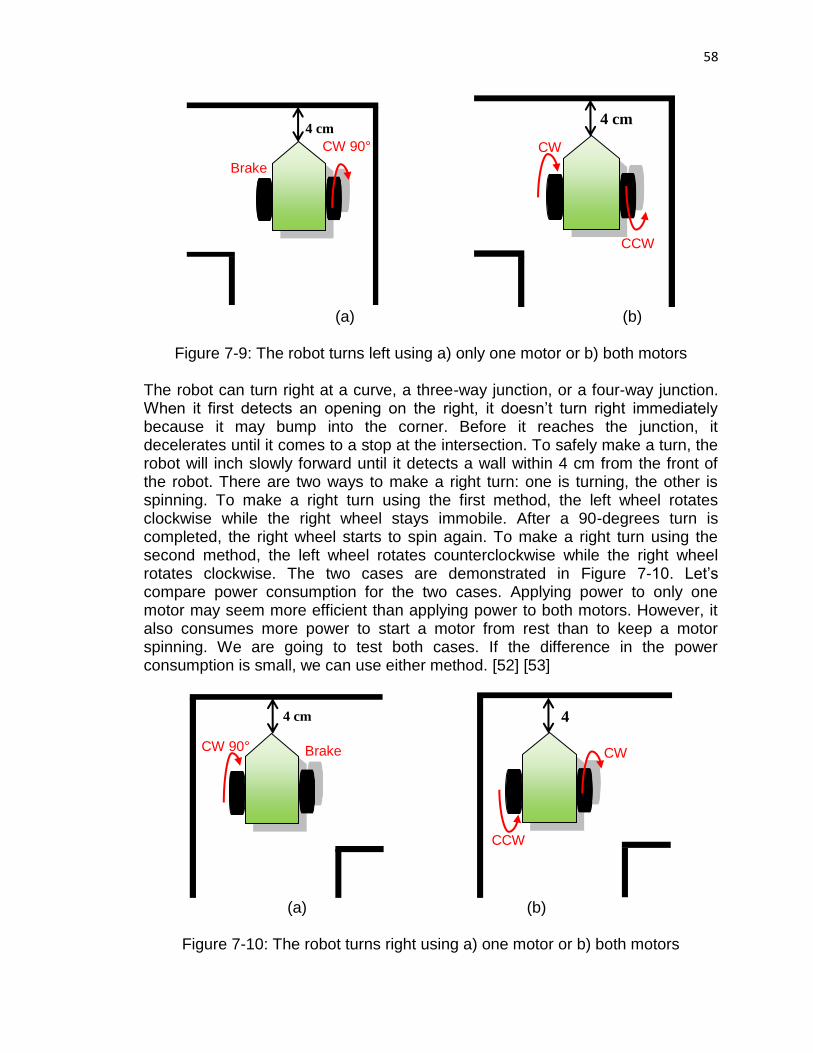
58
(a) (b)
Figure 7-9: The robot turns left using a) only one motor or b) both motors
The robot can turn right at a curve, a three-way junction, or a four-way junction. When it first detects an opening on the right, it doesn’t turn right immediately because it may bump into the corner. Before it reaches the junction, it decelerates until it comes to a stop at the intersection. To safely make a turn, the robot will inch slowly forward until it detects a wall within 4 cm from the front of the robot. There are two ways to make a right turn: one is turning, the other is spinning. To make a right turn using the first method, the left wheel rotates clockwise while the right wheel stays immobile. After a 90-degrees turn is completed, the right wheel starts to spin again. To make a right turn using the second method, the left wheel rotates counterclockwise while the right wheel rotates clockwise. The two cases are demonstrated in Figure 7-10. Let’s compare power consumption for the two cases. Applying power to only one motor may seem more efficient than applying power to both motors. However, it also consumes more power to start a motor from rest than to keep a motor spinning. We are going to test both cases. If the difference in the power consumption is small, we can use either method. [52] [53]
(a) (b)
Figure 7-10: The robot turns right using a) one motor or b) both motors
4
cm
CCW
CW
4 cm
CW 90° Brake
4 cm
CCW
CW
4 cm
CW 90°
Brake

59
The microcontroller detects a dead end when the voltage on all sensors goes low. It responds by telling the robot to turn around. Like left turn and right turn, there are more than one ways to implement a U-turn. The first method is to turn one motor 180 degrees clockwise while the other motor stops moving. The second method is to spin both motors in the opposite direction. One wheel spins clockwise while the other wheel spins counterclockwise. However, the second method is better than the first one because using two motors results in shorter distance than using a single motor. The distance travelled by two wheels is half the distance travelled by one wheel, as shown in Figure 7-11. The width of the passage is more than 20 cm so the robot can turn around as soon as the front sensor is 10 cm away from the wall, given that the left and right sensors detect no opening on their side. Unlike other junctions, the robot doesn’t have to move closely to the front wall to make a turn. It is recommended to power the motors at 75% or less. Full power at 100% may cause erratic movements. On the other hand, power that is lower than 25% may cause the robot to stall. Figure 7-12 sums up the rotations for each turn. [52] [53]
Figure 7-11: Using both wheels results in a smaller distance than using only one wheel
*CW is clockwise. CCW is counterclockwise
Robot action
Turning degrees
Turning technique Spinning technique Left
wheel Right wheel
Left wheel
Right wheel
Turn left 90° Stop CW CW CCW Turn right 90° CW Stop CCW CW
Turn around clockwise
180° CW Stop CCW CW
Turn around counterclockwise
180° Stop CW CW CCW
Go forward 0° CW CW CW CW Go backward 0° CCW CCW CCW CCW
Figure 7-12: Summary of motor actions
CW
CCW
R
CW 180⁰
Brake
2R

60
So how do we know when the robot completes a 180-degree turn? We have to convert the turning angle to the rotational angle of the motors. To U-turn, the robot only needs to make a 180-degree turn, which is half of a circle. To return to its original position one more time, the robot has to complete the whole circle, which is 360 degrees. First, we need to determine the radius of the circular turn. One wheel stays fixed at the center of the circle while the other rotates around it, acting like a compass. Therefore, the radius, denoted as R, is the distance between the two wheels. Next, we need to find the circumference of the circular turn, which is given by Equation 7-9:
Cturn = 2πR (7-9) Now we find the circumference of the wheel, which is given by Equation 7-10, where r is the radius of the wheel.
Cwheel = 2πr (7-10) By dividing Equation 7-9 by Equation 7-10, we have Equation 7-11 [52]:
ϕ =Cturn
Cwheel=
R
r (7-11)
It takes ɸ wheel rotations to complete a 360-degree turn. In other words, it takes ɸ motor degrees to make a 1-degree turn. Therefore, to make a turn of n degrees, we need to multiply ɸ with n, as shown below in Equation 7-12, where ɸn is the number of motor degrees to make an n-degree turn:
ϕn = nR
r (7-12)
7.4 CC110L Transceiver Analysis One of the most important requirements of this project is that the Twinbots can communicate solutions to one another. Since the robots will be implementing two different algorithms for solving the maze and the maze itself will be changing from run to run, both robots must be able to send as well as receive information to effectively communicate through different situations. As much as the design team would prefer to have a “plug and play” method of sending information however that is not generally a luxury that exists and the team must be mindful of all the necessary parameters required to successfully program the Twinbots to communicate effectively. To do this the design team must be able to fully understand the operational characteristics of the chosen communication hardware; this includes how the hardware operates in standby/sleep modes, transmit mode, and receive mode. Another component that must be standardized is the protocol with which all information will be transmitted so that both modules are on the same page when information is set; this includes baud rates, bit configurations, packet size, etc.

61
7.4.1 Data Transfer An important aspect to efficient transmission of data is how it is sent. The C110L has two options for this, data can be sent or received one byte at a time or using a burst from the 64-byte FIFO transfer/ receive registers. The configuration for how data is transmitted and received is set on the header bytes. The bytes concerning burst or single byte access are the only ones of concern here. The CC110L has 64 byte transfer and receive data registers that enable efficient transmission and reception of data. For this project data will most likely be sent using the burst mode to optimize performance and power efficiency when in transmit and receive modes. This can be achieved since all data that will be sent will be ASCII characters that correspond to directions for the robots to follow to solve the maze. Figure 7-13 below summarizes the control state machine of C110L. [54]
Figure 7-13: Control state machine of C110L

62
7.4.2 Microcontroller Interface In most applications, including this project, the CC110L transceiver is interfaced with a microcontroller using a master-slave relationship with the transceiver being the slave. This is done through the SPI (Serial Peripheral Interface) which is a four wire interface to the microcontroller. The four pins through which the CC110L are configured are Serial in (SI), Serial Out (SO), Serial Clock (SCLK), and Chip Select (CSn). This interface is also used to read and write buffered data. All transfers on the SPI are done using a FIFO protocol (MSB first). The SPI pins can be seen in the pin-out shown below for the CC110L. All data transactions start with a header byte that consists of an R/W bit, a burst bit which was referenced earlier and six address bits. When data is being transferred from the MCU to the transceiver the CSn bit will be low as well as the SO bit, if the CSn bit goes high during data transfer, the transfer will be cancelled. One important aspect of the transceiver is how fast the user can expect to receive or transmit data; this is given by Equation 7-13 [54] shown below.
Data Rate = (256+DRATEM)∗2DRATEE
228 ∗ fxosc (7-13)
Where fxosc is the oscillation frequency of the crystal, DRATEM is the mantissa of the user specified symbol rate, and DRATEE is the exponent of the user specified symbol rate.
7.4.3 Packet Handling Since this project will be sending packets of data it is important to discuss how the CC110L handles such data transfer requests. Luckily for the user this transceiver has built in packet handling support. This is accomplished through certain protocols which ensure that data is being transmitted and received correctly and can alert the user to possible errors in transmission. In transmit mode:
A programmable number of preamble bytes
A two byte synchronization (sync) word. Can be duplicated to give a 4-byte sync word (recommended).
It is not possible to only insert preamble or only insert a sync word
A CRC checksum computed over the data field.
The recommended setting is 4-byte preamble and 4-byte sync word which applies to the 1.2 kbaud rate used in this project.
In receive mode, the packet handler unpacks this data checking for the following (if enabled):
Preamble detection

63
Sync word detection
CRC (Cyclic Redundancy Check) computation and CRC to detect errors made in transmitting raw data
One byte address check
Packet length check (length byte checked against a programmable maximum length)
7.5 Software Integration First, we assign pin numbers to the sensors, motors, and the activating switch, which will be declared as global constants at the very beginning of the program. We also specify the inputs and outputs in the set-up subroutine. This function is called only once every time the program is executed. Sensor signals serve as inputs to the microcontroller. The pulse width modulation to the motors will be the outputs. In Energia, we can use pinMode function to initialize, by passing in the pin number and the input or output mode as parameters, as shown in Figure 7-14 [55] [56].
setup()
switch = pin number sensors = pin numbers motors = pin numbers pinMode (switch, INPUT) pinMode(sensors, INPUT) pinMode(motors, OUTPUT)
Figure 7-14: The function of setup subroutine
We will have a main function, which involves the decision-making process of the robot. To simplify the tasks, we develop specialized subroutines that can be called by the main function. Inside the main function, we have two infinite loops that run forever as long as the activating switch is not off. The first infinite loop is used to figure out the maze in the first round. The second infinite loop contains the solution after the maze is solved. Before we can do any maze solving, we need to turn on the robot first. Therefore, the first thing that the main function needs to check is whether the activating switch is on. We use the function digitalRead in Energia to determine if the switch is toggled. If the function returns high, then the switch is on and the robot is ready to move. If the function returns low, then the switch is off and the code stops executing. Then, the main function calls sensor subroutine, shown in Figure 7-15, which inputs sensor data and determines what type of passages the robot encounters. [55] [56]

64
Figure 7-15: Subroutine that reads sensor inputs
In Energia, we can use the function analogRead to read sensors’ analog outputs, which are represented by integers from 0 to 1023. If the left and right sensors do not yield high analog values but the front sensor does, then the robot is on a straight path searching for the next junction. The main function contains an array that keeps track of the current path. Therefore, an S is placed into the array. Next, the main function calls the PID control subroutine, shown in Figure 7-16, which helps the robot travel in a straight line and maintains safe distance between the two walls on both sides. The PID control subroutine executes the PID equation mentioned in section 6.2. The subroutine contains an infinite loop which continuously takes in sensor reading to ensure that the robot maintains a straight path at all time. [55] [56]
To keep the robot stable, the maximum power delivered to both motors should be set at 50 percents only. In Energia, we can use the function analogWrite to drive the motors at various speeds. The frequency of the pulse width modulation used in this function is approximately 490 hertz. We need to pass in the pin number and the duty cycle as parameters. The duty cycle ranges from 0 to 255. At 0, the motors are always off and at 255, the motors are always on. So at 50 percents, the duty cycle should be around 127, which is about half of 255. Once the robot successfully follows a straight line, both motors can operate at the same power. We should include a delay every time we change the motor power so that the mechanical parts have time to respond. To pause the program, we only need to use the delay function in Energia. If the front sensor detects a wall ahead, low power is applied to the motors to slow down the robot. When the robot can no longer go straight, we exit the subroutine and return to the main function.
ReadSensors()
If analogRead(left sensor) = LOW and timer = 5 seconds
Return E If analogRead(left sensor) = HIGH
array = L If analogRead(front sensor) = HIGH
array = S If analogRead(right sensor) = HIGH
array = R Else array = B
Output: E, L, S, R, B

65
PIDControl() Infinite loop ReadSensors() If S is not found, exit the loop Control function Output = KP*Proportional + KI*Integral + KD*Differential Limit power to a maximum value If output > maximum Output = maximum If output < -maximum Output = -maximum If output < 0, turn left analogWrite(maximum + output, maximum) delay() If output > 0, turn right analogWrite(maximum, maximum - output) delay() If output = 0, go straight analogWrite(maximum, maximum) delay()
Figure 7-16: PID control subroutine
The microcontroller continues to take in sensor data. If the robot encounters a junction or a dead end, the turning subroutine in Figure 7-17 is called and an L, R, or B is put in the path array. To rotate, the same power is delivered to both motors. However, the signs are opposite, which means the motors are spinning in opposite directions. For an example, if the left motor is powered at 60, then the right motor is powered at -60. After that, we add a delay. To turn left or right, the robot only needs to rotate 90 degrees. However, to turn around, the robot needs to rotate 180 degrees. Therefore, the delay to make a U-turn doubles the delay of a left or right turn. [55] [56]

66
Figure 7-17: Turning subroutine If the robot hits a dead end, we call the subroutine that can simplify the path. Our goal is to get rid of dead ends. Therefore, we need to eliminate all the B characters in the array. Figure 7-2 shows that the dead-end junctions always have a B character in the middle and are represented by 3 letters. Therefore, we need to scan the last 3 entries in the array. The second to last entry should contain a B. In Figure 7-2, LBS and SBL can be both substituted by R. Therefore, the order of the letters is not important. We can infer from this that R can serve as a substitute whenever an L and an S go together. In other words, LBS will make the same angle as SBL. Instead of matching every single letter with the table in Figure 7-2, we count the total angle that the robot makes. An S makes 0 degree; a B makes 180 degrees; both L and R make 90 degrees. However, R is in the opposite direction of L so it actually makes a -90 degrees, which are equivalent to 270 degrees. Summing them together will give us 5 different total angles. In Figure 7-18, RBR and LBL give 2 different angles, which are the multiple of 360 degrees. To simplify, we do modulo operation on the total angles, which yield 4 distinct results that match with 4 substituting letters, L, R, B, and S. After we find the substituting letter, we erase the last 3 entries and replace them with a new entry. Now, the array is shortened and the solution is simplified. Figure 7-19 shows how the software is implemented. [55] [56]
Input: L, R, B
TurningControl() Slow down analogWrite(low power, low power) delay() If L, turn left analogWrite(-power, power) delay() If R, turn right analogWrite(power, -power) delay() If B, turn around analogWrite(power, -power) double delay()

67
Sequence of turns
Substituting letter
Total angles Modulo angles
SBR
L
0° + 180° + 270° =
450°
450° % 360° =
90° RBS
LBS
R
90° + 180° + 0° =
270°
270° % 360° =
270° SBL
LBR
B
90° + 180° + 270° =
540°
540° % 360° =
180° RBL
RBR
S
270° + 180° + 270° =
720° 90° + 180° + 90° =
360°
720° % 360°
= 360° % 360° = 0°
LBL
Figure 7-18: Matching letters with turning angles
SimplifyPath()
Search for B in the second last entry of the array If B is not found, exit the function
If angle = 90 Replace XBX with L If angle = 270 Replace XBX with R If angle = 180 Replace XBX with B If angle = 0 Replace XBX with S The path is shortened
Array length - 2
Figure 7-19: Subroutine that simplifies the path by deleting B sequence in the
array
So far, we have been using the left-hand rule. If the left sensor does not detect walls in 5 seconds, then the robot has left the maze. The sensor subroutine will return the letter E. The first main loop is aborted and the program continues to the second main loop. The robot already obtained the solution so it only needs to

68
follow the path written in the array to find the exit. Figure 7-20 shows the software integration of the main function and its subroutines.
Figure 7-20: Software integration of the main function and its subroutines
Main Loop Decision-making Process
First infinite loop Maze solving
Check if the robot is turned on digitalRead(activating switch) = HIGH
Second infinite loop Maze solved
If sensors change from high to low
or low to high, the robot detects the next junction
Read solution array
setup() Assign pins to motors, sensors, and switch
Specify inputs and outputs
ReadSensors() Search for open
paths
PIDControl() Maintain a
straight path
TurningControl() Adjust power on motors to make
turns
SimplifyPath() Eliminate dead
ends in the solution
E
L, R, or B S
S
L or R
End
Program
E

69
7.5.1 Communication Integration A key feature of this project is that it uses wireless communication as a core tool to complete its task. At the end of every run the first robot that finishes firs will transmit the solution to the entire maze back to the slower robot. To do this there are a few things that need to be understood.
The solution will be communicated in an array of characters corresponding to turns
Communication will only happen when one robot completes the maze successfully
The robot that is receiving the solution will communicate that the solution has been sent using a “received” message flag
The process for implementing this algorithm is fairly straightforward, especially since the team will be using the Energia IDE to code the project. This allows the team to code at a high level and focus on solving problems instead of manipulating bits. Since the robots will have forward facing sensors they will only be sensing what direction to move in the forward direction. When the sensors take in data they obviously read them in as voltages where a higher voltage corresponds to a closer object and vice versa. When the first robot completes the maze there will be nothing in front of it to initiate a significant enough voltage to cause any turning action; this will signal to the robot that it has completed the maze successfully and can now stop. Once the first robot has completed the maze the communication protocols will commence and the solution will be transmitted to the second robot. While the first robot is transmitting the solution back to the second robot another problem arises: there needs to be a way for the first robot to know when to stop transmitting. This problem has a simple solution; as each robot works through the maze they will store a counter that will be used for the loop counter while the solution is being transmitted. This will allow the robots to transmit the data more efficiently and avoid any guessing games that could be involved with the length of the array and result in incomplete solutions being transmitted or solutions with too many extraneous transmissions. Another important consideration is when and how to utilize the burst transmission capabilities of the Anaren RF module. As stated in the communication hardware section each module has a 64-byte transmit and receive FIFO buffer that allows for burst transmissions. This could increase the robots transmission efficiency greatly since the robots could transmit many characters using this feature. The downside to this is that if care is not taken with using this feature the robots could transmit unwanted data that could degrade the integrity of the solution causing unwanted motion after the maze has been solved. To solve this problem there will be two lops for transmission. The first loop will utilize the burst capabilities of

70
the RF module to transmit the bulk of the solution. This will be done as long as even 64-byte packets can be sent. Once there are no more 64-byte packets the second loop will be entered and the remaining turns of the solution will be computed.
8 Prototyping and Testing To create a working PCB design, the team decides to follow three processes. The first process is testing on a breadboard. Depending on how much time the team has and how far the team wants to go into testing, the electronic components can be soldered on a perf or prototype board for another process of testing. This intermediate step is optional. It’s better to test on a perf board than a breadboard because electronic components are more tied down, allowing more accurate current and voltage readings. On the breadboard, components may be loosely connected, producing incorrect data. Besides, a prototype board resembles the final product more than a breadboard. The second process is designing PCB layout using a PCB design software. Then the group would send the design layout to a PCB manufacturer to have the PCB fabricated. The final process is to solder the components on the fabricated PCB and test them. Usually semiconductor integrated circuits such as voltage regulator are available as surface-mount device (SMD) or through hole components. Through hole mounting involves placing components’ lead wires through holes on the printed circuit board (PCB). They are then soldered permanently on the board. Surface mounting is a newer mounting technique resulted from a high demand for lighter weight and smaller components. This method involves soldering the devices on the printed circuit board surface directly. Compared to through hole technology, surface mounting saves more space and allows more pins. Through hole components are ideal in applications that constantly need replacements. They are perfect for our project because we can test them on breadboard as well as solder them on the PCB. Surface mount devices are not as favored in bread boarding as in PCB designing and testing. [57] Precautions should be taken before replacing a fuse. It’s not advisable to replace a fuse with one that has higher amperage and lower voltage ratings. Consider an arbitrary fuse that has an amperage rating of 1 A and voltage rating of 15 V to protect a device that can only handle up to 1.5 A from a 12 V battery. This fuse only allows a maximum of 1 A to flow through it, thus, ensuring that the device would be protected. Suppose this fuse is replaced by a second one with an amperage rating of 2 A and voltage rating of 10 V The second one allows more current to flow into the device and thus, damaging it. The 10 V rating wouldn’t be able to support a 12 V battery. Replacing a fuse with the wrong one can result in no protection or blow up the fuse. It’s acceptable to decrease the amperage rating and increase the voltage rating. Understanding fuse’s interrupting rating is important in order to handle the fuse safely. The interrupting rating indicates the maximum amount of short-circuit or fault current that the fuse can safely

71
withstand. The interrupting rating should be higher than the fault current in the circuit. Otherwise, the fuse could rupture or explode. [58] Sparks that occur near batteries can ignite hydrogen gas and pose safety risks to the users. When connecting or disconnecting charging equipment to a battery pack, remember to disconnect first or connect last at a location away from the battery. It’s not recommended to connect the motor’s power port to the microcontroller’s power supply pin because powering the motor directly from the microcontroller may drain significant amount of current from the microcontroller. The servos should be powered by an external power supply. [59] It’s best to double check the connections before the battery or power source is turned on in case we introduce a short or reverse polarity. Always make sure that all devices are grounded properly. Determine the positive and negative leads of components such as capacitors and LED before connecting. When connect polarized capacitors and LED, make sure to connect the longer leg to positive and shorter one to negative or ground. Reversing the LED’s polarity might fry the component.
8.1 Breadboarding A good practice for testing and prototyping is to take notes of observations and data so that if a problem occurs, our team can go back and resolve it quickly. Before a resistor is placed on a breadboard, our team should ensure that the resistance value is determined by an online resistor calculator. If a component is a surface mount device (SMD) that has pins sticking out of its sides, then alligator clip shall be used to connect it with other components. Use a multimeter and measure the amount of current drawn to the servos in the presence of no load and full load to understand how much the practical values deviate from the datasheet’s values. Make sure that the full load does not draw more current than the battery pack can supply. In case it does, replace another battery pack that can support higher current draw. The group will power the motors using a power supply in the lab before actually testing with a battery pack. It’s best to set the current as low as possible then verify that the motors draw the right amount of current before slowly increasing the current. Measure the input and output voltage as well as the input and output current of the voltage regulator then calculate the wasted power using Equation 8-1 [34]. If the power loss is within 1 watt, then no heat sink is required. If a linear regulator wastes more than 1 watt of power, then it should be replaced by a switching regulator. Wasted power = (input voltage – output voltage) x output current (8-1) Next, calculate the voltage regulator’s efficiency based on Equation 8-2,

72
Efficiency = output power
input power × 100 =
output current × output voltage
input current × input voltage × 100 (8-2)
If the LM2937 LDO regulator is used to regulate the voltage, then dissipated power, PD should be calculated in order to determine if a heatsink is required. Refer to Equations 8-3 to 8-4 and Figure 8-1 to calculate PD. Note that IG is not quiescent current. It is the current at the ground. After PD is calculated, the maximum allowable temperature rise TR (max) must be calculated using Equation 8-5. TA (max) is the maximum ambient temperature. Next, the maximum allowable value for the junction-to-ambient thermal resistance RθJA can be found from Equation 8-6. No heatsink is needed if RθJA satisfies the conditions listed in the third column of Figure 8-2. [60]
Figure 8-1: LDO regulator power dissipation diagram
IIN = IL + IG (8-3) PD = (VIN – VOUT)IL + (VIN) IG (8-4)
TR (max) = TJ (max) – TA (max) (8-5) RθJA = TR (max)/ PD (8-6)
LM2937 Package TJ (max) OC
RθJA (°C/W) Conditions For No Heatsink
TO-220 TO-263
125 ≥ 53
≥ 80
SOT-223 85 ≥ 174
Figure 8-2: LM2937 LDO regulator’s RθJA conditions for no heatsink
VIN
IIN
IL
IG
VOUT

73
8.2 Printed Circuit Board (PCB) Design
8.2.1 Voltage Regulator Layout The TPS6123x datasheet [61] provides layout guidelines and example to follow which would be useful in the future when the team designs a PCB layout. In the datasheet, only the TPS61230 and TPS61231 IC pictures are shown. These ICs have the feedback pin which might not be available in the TPS61232 product. The pin is only needed when adjustable output is required. Based on the datasheet, if the power supply is located more than a few inches from the IC, then 47 µF tantalum or electrolytic capacitors may be required besides the bypass capacitors. The inductor, input and output capacitors should be placed as close as possible to the converter. In case the capacitor’s size prevents it from being placed close to the to the VOUT and GND pins, then a 1 µF capacitor connected in parallel should be used. The datasheet recommends to use a small X5R or X7R ceramic capacitor for the output and input decoupling capacitors. Larger values may be used for C1 to reduce input current ripple. If a TPS63061 buck/boost regulator is used to regulate voltage, then we need to pay close attention to the datasheet. In order to minimize the ground noise effects, the datasheet recommends using a common node for power ground and another one for control or logic ground. Both nodes must be connected on the PCB at only one point that is close to the GND pin. The power ground is notated as PGND in the datasheet. The logic or control ground is GND. The PowerPad, shown on page 4 of the datasheet, needs to be connected to PGND and has to be soldered in order to reach appropriate power dissipation. [62] The LM2937 LDO regulator is available in three packages: TO-220, SOT-223, and DPAK/TO-263. Among the three, the TO-220 has longer pins which are perfect for testing on breadboard. The DPAK/TO-263 is a surface-mount package that would be used on the PCB. We might also use the SOT-223 on our printed circuit board because it has the smallest size. The three packages and their size are listed on the first page of the datasheet. The DDPAK/TO-263 and SOT-223 packages use a copper plane on the PBC and the PCB itself as heat sink. In order to optimize heat sinking, the tab should be soldered to the plane. The tab is connected to GND pin internally. It can be left floating. If a SOT-223 is soldered on a PCB, then soldering techniques for the package should be taken into consideration. Either vapor phase or infrared reflow techniques are preferred. Hand or wave soldering is not recommended because excessive temperature may crack the package. [60] The LM2937 or any regulator’s performance depends on the PCB layout. If the layout is not properly done, then power supply rejection ratio (PSRR), noise, and transient performance may be degraded. Figure 8-3 only serves as an example for our team to follow when we layout the PCB. CIN and COUT should be on the same side of the PCB as the regulator to achieve best performance. Connections

74
through vias, long trace length, and narrow trace width should be avoided because they add parasitic resistances and inductances which would reduce the performance, particularly during transient state. [60]
Figure 8-3: LM2937 SOT-223-4 layout (Reprinted with permission from Texas Instruments)
8.2.2 Final Power Supply Design For our final power supply we chose to use the LMR61428, a boost switching regulator with an adjustable output that we configured for a 5V to supply the sensors and Servo motors. We also used the REG113, a 3.3V fixed output LDO to supply our microcontroller and Anaren AIR module. The schematic is shown below in Figure 8-4.
Figure 8-4: Power supply design

75
8.2.3 Anaren AIR Module Layout The Anaren Air module has some added benefits related to the PCB design of the project. The Anaren Air module has a shielded package which makes it suitable for a two layer PCB design, this help keep the design simple and inexpensive. Also, since the Anaren Air module family all have a similar footprint and are all configured using the same pin layout the design team can elect to change the specific module that is used without having to redesign the PCB connections for communication. There are multiple ways that this module can be mounted onto a PCB; Figure 8-5 below goes over the suggested ways of doing so to allow for proper operation. [36]
Figure 8-5: Different methods of mounting (Reprinted with permission from Anaren)
As shown in the Figures 8-5 and 8-6 there are many ways that this component can be mounted as long as the proper ground plane procedures are followed. This gives the design team a lot of flexibility on the placement of this component.
Figure 8-6: Different methods of mounting (Reprinted with permission from Anaren)

76
To allow for wireless communication between the two robots the team used the Anaren AIR module to implement sub GHz RF communication. The schematic for this interface is shown below in Figure 8-7. The Anaren BoosterPack’s pinout was used as a reference to understand which pins were needed for proper operation of the AIR module.
Figure 8-7: Anaren AIR module interface design
8.2.4 Program Microcontroller on PCB During the prototyping and initial testing phases the project will be implemented using an MSP430F5529LP LaunchPad. THs will provide the design team with a quick method of implementing the maze solving algorithm and interfacing the major components of each robot such as the MCU, Servos, Sensors, and Wireless Communication. One of the advantages of using the LaunchPad to prototype the project is that it has an emulator board on it that is used to program the microcontroller. The microcontroller cannot be programmed properly without this. However, for the final design the project will obviously not be using a LaunchPad, but rather a custom designed PCB with the microcontroller and all other components surface mounted. The emulator board is not a simple set of components but rather a complex and high level emulator module that is beyond the scope of the design team. Also, the emulator board physically takes up a
77
considerable amount of board space. The design team has made a decision to use the emulator board on the LaunchPad to program the MCU on the custom PCB for the final design. This seemed to be the most cost, time, and space efficient way to implement the design without having to redesign a Texas Instruments Emulation board. To use the emulator board from the LaunchPad to program the custom PCB the design team must isolate the emulator board from the LaunchPad and replace the on board MCU with the MCU on the custom PCB. This is done by using the target isolation jumper block on the LaunchPad. Instead of constructing the entire emulation board the design team will simply design the PCB so that jumper wires from the jumper block can be attached temporarily to set the MCU on the PCB as the target device for the emulation board. After considering different options and time constraints it seems that this will be the most efficient method to be able to use the emulator without having to reinvent it.
8.2.5 Final Programming Interface Design After having many issues programming the microcontroller using the spy-bi-wire connections from the LaunchPad emulator, the team decided to switch to four wire JTAG programming instead. This decision was made do to the sensitivity of Spy-Bi-Wire to board capacitances and other interference form switching power supplies and other sources. JTAG is more robust since it uses four wires instead of two wires to do the same thing as spy-bi wire which removes the sensitivity of the clocking procedures needed to program via spy-bi-wire. To use JTAG the team procured a FET430-UIF flash emulation tool. After making this design change the team was able to load programs onto the MCU much easier; also, the FET430-UIF had the added feature of preserving UART communication which was used extensively in testing. As mentioned earlier the team decided to switch from Spy-Bi-Wire programming to the more reliable JTAG programming using the FET430-UIF Flash Emulation Tool. A reference design from the MSP430F5529 Experimenter board was used to design the portion of the PCB; the resulting, final, design is shown below in Figure 8-8.

78
Figure 8-8: JTAG interface for programming the MCU
8.2.6 Soldering While soldering may seem trivial to the experienced engineer or hobbyist, none of the design team members have ever done it before. Since it is such a fundamental skill in electrical engineering and none of the team members have done it before, time will be taken here to gain some knowledge about how to solder. Soldering is a process used to join different metal components together. This is accomplished by using a metal alloy (solder) to connect the different pieces by melting the solder onto the components and allowing it to cool. This creates a bond that is strong enough to hold the components together and also conduct electricity. Soldering is different from other methods used to fuse metals together such as welding because it occurs at a lower temperature (around 400 degrees Fahrenheit). Also, soldering melts a filler material between two metals to create contact unlike welding which actually melts the independent metals and fuses them together. Soldering can be “undone” for this reason by melting away the solder when it is desired to do so. 8.2.6.1 Soldering Tools
1. Soldering Iron The size of the soldering iron depends on the application. A 15-40 watt soldering iron is good for circuit board soldering while 60-140 watt iron is better for thicker materials. Using a higher power iron on small components can result in overheating and damage to the components.

79
Some soldering irons have variable temperature so that most applications can be accomplished with one iron however they are much more expensive.
2. Solder
Solder comes in a variety of thicknesses depending on what it is needed for. For circuit board applications thinner solder is better since it is more detailed work. Most solder material is combination of lead and tin but nowadays lead is being phased out of design due to health concerns. Some solder contains silver as well which results in a higher melting temperature which can result in burning components if care is not taken. Apparently solder with rosin core is better to use because it acts as a flux and helps the connection.
3. Soldering iron tips
Soldering irons come with tips but it is good to know what tips are better suited for certain applications. For detailed work, it is better to use a conical shaped tip while a flat larger tip is good for joining wires together. Also, the tip should be slightly smaller than whatever is being soldered.
4. Soldering iron holder and cleaning sponge
This just provides a safe place to hold the iron while not in use and a safe means of cleaning the tip.
5. Tools for wires and clips to hold work
Wire clippers and wire strippers for cutting and stripping wire. Also good clips to give extra hands while soldering pieces together are necessary such as “helping hands” or just alligator clips, anything to help make the soldering process easier.
6. Safety equipment
These include exhaust fans so that fumes are not being inhaled and safety goggles.
8.2.6.2 Soldering Procedure
1. Heat up soldering iron and clip all components together onto clips in the proper orientation such that the board can be flipped upside down and not have everything fall off.
2. Clean tip of soldering iron with a wet sponge.
3. (Soldering Wires together) Strip about half an inch away from the ends of the wires and twist them together to form your joint. Touch the soldering iron to the joint (not the solder) and begin to heat the wires. Touch the solder to the wires (not the iron) and wait until it melts into the joint. If you
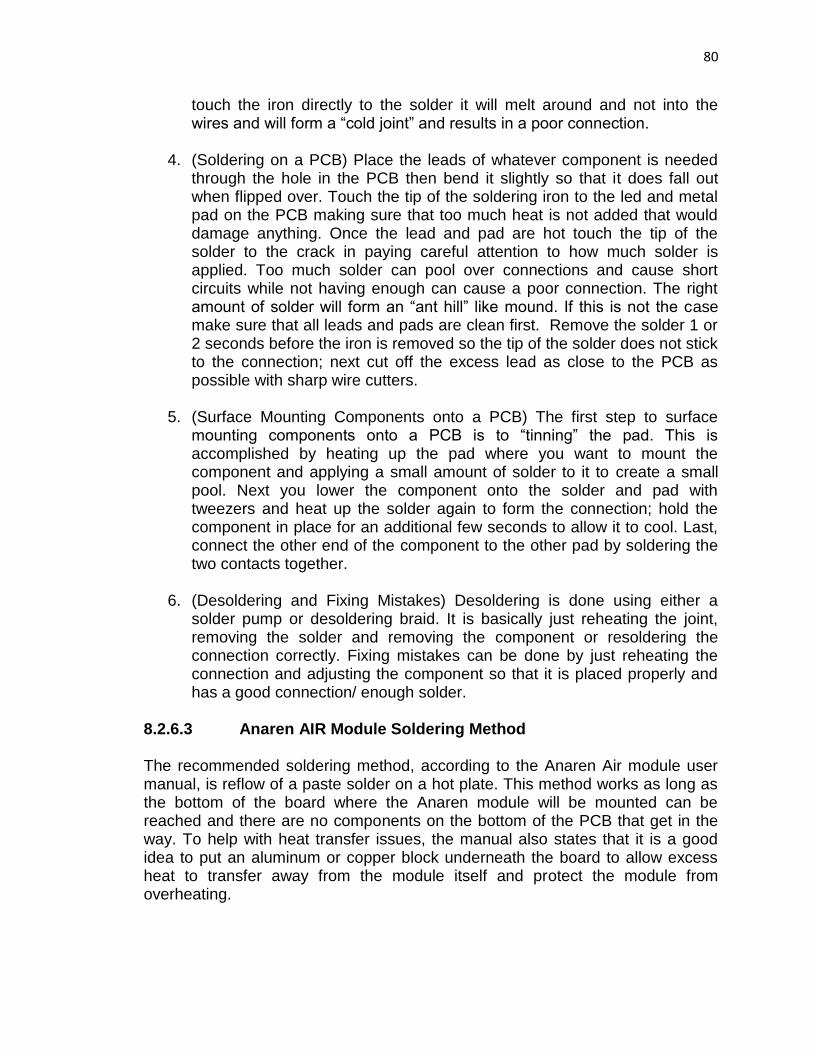
80
touch the iron directly to the solder it will melt around and not into the wires and will form a “cold joint” and results in a poor connection.
4. (Soldering on a PCB) Place the leads of whatever component is needed
through the hole in the PCB then bend it slightly so that it does fall out when flipped over. Touch the tip of the soldering iron to the led and metal pad on the PCB making sure that too much heat is not added that would damage anything. Once the lead and pad are hot touch the tip of the solder to the crack in paying careful attention to how much solder is applied. Too much solder can pool over connections and cause short circuits while not having enough can cause a poor connection. The right amount of solder will form an “ant hill” like mound. If this is not the case make sure that all leads and pads are clean first. Remove the solder 1 or 2 seconds before the iron is removed so the tip of the solder does not stick to the connection; next cut off the excess lead as close to the PCB as possible with sharp wire cutters.
5. (Surface Mounting Components onto a PCB) The first step to surface
mounting components onto a PCB is to “tinning” the pad. This is accomplished by heating up the pad where you want to mount the component and applying a small amount of solder to it to create a small pool. Next you lower the component onto the solder and pad with tweezers and heat up the solder again to form the connection; hold the component in place for an additional few seconds to allow it to cool. Last, connect the other end of the component to the other pad by soldering the two contacts together.
6. (Desoldering and Fixing Mistakes) Desoldering is done using either a
solder pump or desoldering braid. It is basically just reheating the joint, removing the solder and removing the component or resoldering the connection correctly. Fixing mistakes can be done by just reheating the connection and adjusting the component so that it is placed properly and has a good connection/ enough solder.
8.2.6.3 Anaren AIR Module Soldering Method The recommended soldering method, according to the Anaren Air module user manual, is reflow of a paste solder on a hot plate. This method works as long as the bottom of the board where the Anaren module will be mounted can be reached and there are no components on the bottom of the PCB that get in the way. To help with heat transfer issues, the manual also states that it is a good idea to put an aluminum or copper block underneath the board to allow excess heat to transfer away from the module itself and protect the module from overheating.

81
Set the hot plate to the reflow temperature recommended by the manufacturer
Apply solder paste to the pads on the board receiving the AIR module
Place the AIR module carefully onto the dispensed solder
Using tweezers or another holding device, carefully place board with AIR module onto the hot plate surface (or metal block)
Apply heat until reflow occurs, according to solder paste manufacturer’s recommendations
Remove the board and place on a heat-resistant surface to cool
Double check all connections to verify that no opens or shorts have occurred
8.2.7 Final Hardware Design The final design of our hardware was very similar to the original design since we still had to interface a microcontroller to a power supply and multiple sensors and servos. However, it took the team multiple attempts to get a functioning PCB. Three design iterations in total. The first major problem the team had was that using the Spy-Bi-Wire programming method, the team could not program the microcontroller successfully. After researching the common problems with Spy-Bi-Wire we found that it was very sensitive to internal board capacitances, line capacitances and had a very sensitive clocking scheme to convert its normally four wire JTAG operation to a two wire configuration. After wasting hours trying to fix this issue the team decided to abandon Spy-Bi-Wire and switch to JTAG. This allowed us to program the microcontroller easily as well as maintain our UART capabilities. The schematic and PCB layout for the final design are shown below in Figures 8-9 and 8-10, respectively. Throughout the hardware design phase of this project, the team learned many hard lessons through failed attempts at designing the system. First, the team learned that reference designs should be used whenever they are applicable to the design of a system. Only when a reference design for interfacing the microcontroller to a JTAG emulator was used was the team able to successfully flash the microcontroller. The team did, however, use reference designs for the power supply which worked perfectly on the first design iteration. The next lesson that was learned was to very slowly double and triple check the design schematic to make sure that all components are connected properly to correctly reflect the design. The second design iteration failed due to the absence of a junction in the schematic capture of the system in the power supply. Another thing that was learned was to make sure that the board being designed is not too big for the application; the second board was nearly too big for the robot chassis. The last, and most important, lesson learned was that prototyping the entire is system is the most important thing that can be done to achieve success. This means using breakout board to prototype small ICs and MCUs and connecting the entire system before a PCB is designed.

82
Figure 8-9: Schematic of the final system design
Figure 8-10: Final PCB layout

83
8.3 Working with Motors
8.3.1 Centering Servos Manufactured continuous-rotation servos often have trimmer potentiometer which replaces the traditional feedback potentiometer. The trim pot allows the user to calibrate the servo through a hole in the side of the servo case. To center the servo, connect the servo to a microcontroller and send a centering signal to the servo. Then simply insert a Phillips head screwdriver’s tip into the hole and gently twist the potentiometer in either direction until it stops turning. A standard servo doesn’t have the access hole for calibration. However, a Parallax standard servo can be modified for continuous rotation and centered with the following procedure. [13] [63]
1. Remove the four screws at the bottom of the servos, as shown in Figure 8-11.
Figure 8-11: Parallax standard servo’s bottom view
2. Unscrew the servo horn and pull off the top cover, as shown in Figure 8-12.
Figure 8-12: Parallax standard servo’s side view
Top cover
Remove this screw
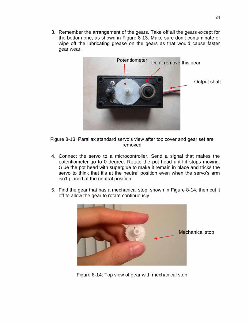
84
3. Remember the arrangement of the gears. Take off all the gears except for the bottom one, as shown in Figure 8-13. Make sure don’t contaminate or wipe off the lubricating grease on the gears as that would cause faster gear wear.
Figure 8-13: Parallax standard servo’s view after top cover and gear set are removed
4. Connect the servo to a microcontroller. Send a signal that makes the
potentiometer go to 0 degree. Rotate the pot head until it stops moving. Glue the pot head with superglue to make it remain in place and tricks the servo to think that it’s at the neutral position even when the servo’s arm isn’t placed at the neutral position.
5. Find the gear that has a mechanical stop, shown in Figure 8-14, then cut it off to allow the gear to rotate continuously
Figure 8-14: Top view of gear with mechanical stop
Don’t remove this gear Potentiometer
Output shaft
Mechanical stop

85
6. Remove the slot from the gear that was connected to the potentiometer, shown in Figure 8-15, so that the pot wouldn’t rotate when the gear rotates.
Figure 8-15: Bottom view of top cover with gears
7. Reassemble everything.
8.3.2 Motor Tests Since wheels are attached directly to motors. The direction of rotation of the motor corresponds to that of the wheel. Based on observations and common sense, direction of rotation of each wheel can be easily found for different types of turn or movement that the robot makes. Figure 8-16 summarizes the direction of rotation given the types of movement.
Direction of Rotation
Movement Left Servo Right Servo
Turn right Counterclockwise Counterclockwise
Turn left Clockwise Clockwise
Turn around Either clockwise or counterclockwise
Go forward Counterclockwise Clockwise
Go backward Clockwise Counterclockwise
Figure 8-16: Servos’ direction of rotation given types of movement
Notice that the left and right servo can rotate in either direction for the robot to turn around. If both servos turn clockwise, then the robot turns around in the counterclockwise direction. Likewise, the robot turns around clockwise if both servos turn counterclockwise.
Slot

86
The team also performed multiple tests on pulse widths to determine the right speed of the servo motors to move forward, backward, turn right, turn left, and turn around. Since the servo doesn’t rotate significantly with a single pulse, a relatively large number of pulses were used for both the left and right motors in order to be able to observe how far the robot moves or how much it turns. First, an arbitrary pair of clockwise or counterclockwise pulse widths are chosen in which one is sent to the left servo and the other to the right servo. This pair of pulse widths is sent simultaneously then followed by a 20 ms delay. The pair of pulse widths and 20 ms delay are sent multiple times to the servos until a noticeable full turn is achieved. The turns are not exactly 90° and 180° because they are implemented purely based on visual observations. Precision is not necessary for the maze solving application. Figure 8-17 lists different pairs of pulse widths and the corresponding number of pulse pairs for each turn.
Left and Right Servo Pulse Width (us)
Number of Pulse Pair
Turn left 90° 1450 39
1470 65
1400 27
1300 27
Turn right 90° 1550 39
1530 65
1600 27
1700 27
Turn around 180° Either 1450 or 1550 78
Either 1470 or 1530 130
Either 1400 or 1600 55
Either 1300 or 1700 48
Figure 8-17: Pulse width modulation testing
The team also performed multiple tests to see if the distance is directly proportional to the number of wheel revolutions. To implement this, the same process is used as in turning left, right, and around. Again, a pair of pulse widths is sent to the servos but this time one is counterclockwise and the other is clockwise. In this case, the number of pulse pairs is not determined by observing if the robot makes a full turn but by random selection. First, mark the starting position of one of the wheels with chalk or pencil. Next, send an arbitrary number of pulse pairs to make the robot moves. Once the robot stops moving, mark the stopping position of the wheel. Then measure the distance from the starting position to the end with a ruler. Repeat the process with a different number of pulse pairs. The number of pulse pairs corresponds to the number of revolutions. Therefore, if the distance is directly proportional to the number of pulse pairs, then it’s also directly proportional to the number of revolutions. The linear

87
relationship is shown in Figure 8-18. For a 1550 us and 1450 us pair, the distance can be related to the number of pulse pair as shown in Equation 8-7,
Distance ≈ number of pulse pair/5 (8-7) For the 1530 us and 1470 us pair, the relationship is expressed in Equation 8-8,
Distance ≈ number of pulse pair/7.5 (8-8)
In both cases, the relationship is linear but the proportionality constant changes for different set of pulse widths.
Left Servo Pulse Width (us)
Right Servo Pulse Width (us)
Number of Pulse Pair
Distance (cm)
1550 1450 20 4
50 11
1530 1470 30 4
85 11
Figure 8-18: Distance vs. number of pulse pair
8.4 Interpret Sensor Data There are 3 steps in sensor interpretation:
Calibration and gather sensor data Graph sensor data Generate a best-fit line
Let’s start with the calibration process. Sensors do not always yield the same output for the same input even if they are tested under the same environment. The same range can correspond to multiple different output voltages. Therefore, we need to calibrate the sensors before actually using them. First, we put a wall in front of a sensor and vary the distance between them. We only change certain variables while keeping other factors the same. In the calibration test, the independent variable is the distance between the sensor and the wall. The dependent variable is the output voltage of the sensor. The constant factors are the wall, the sensor, and the lighting condition. Next, we use a ruler to measure the actual distance between the sensor and the wall. This physical distance is different from the distance calculated by the microcontroller. The measured distance serves as a reference for our verification of the calculated distance. We can also calibrate different sensors at the same time. Even two sensors are of the same type, they don’t necessarily return the same values for the same distance. It is highly recommended to perform the same test multiple times for accuracy. The sensor is likely to behave erratically at the lower and upper ends of the range. Therefore, we need to pay attention to the output voltage around 4 cm and 30 cm. At 4 cm, we expect to see very high voltage. At 30 cm, we expect

88
to see very low voltage. It is a good idea to do more tests where the data fluctuate. Sensor noise can also affect sensor reading. Sharp infrared sensors are pretty immune to outside interference so it should not cause too much problem. However, small noise is still expected. To get rid of the noise, we only keep the average values of the data points. Therefore, we need as many data points as possible to make an accurate graph, especially if it’s nonlinear. Sometimes sensors fail to read distance correctly because reflective object has clear boundary line. To solve this problem, the sensor is placed orthogonal to the boundary line, shown here in Figure 8-19. We are not dealing with moving objects. However, moving sensors can also potentially cause problem. It is recommended to position the sensors in parallel to the moving direction, as shown in Figure 8-20. [47] [64]
Figure 8-19: Sensor positioning relative to boundary (Reprinted with permission from Digi-Key)
Figure 8-20: Sensor positioning relative to moving direction (Reprinted with permission from Digi-Key)
The second step is to log the data in Excel and create a graph. There are several patterns that we need to observe. First, the graph may not be continuous. This often occurs at very close range, especially for distance less than 4 cm. Secondly, the graph is very likely to be nonlinear. Therefore, we need to linearize the graph. We can remove the lower end and the upper end of the graph where the data fluctuate a lot. What we have left is a scatter plot that resembles some kind of equations. If we plot output voltage on the y-axis and distance on the x-axis, we’ll end up with a graph that resembles an inverse equation such as 1/x, as shown by the datasheet in Figure 8-21 [47]. To generate a best-fit curve for this graph, we need sophisticated math program that uses floating point. Unfortunately, this adds to CPU compute time and increases power consumption. Another approach is to use piecewise linear approximation. Basically, we cut the curve into smaller linear pieces and match each of them with linear equations. However, this method takes up a lot of memory space. To get an accurate graph, we need a large number of infinitesimal segments. The

89
last option is to use information from the sensor datasheet and work from there. [64] The sensor datasheet includes two graphs, one is curvy and the other is almost linear. We choose to work with the second graph. As shown in Figure 8-22 [47], the analog output voltage is not related to the distance itself, but the inverse of distance. The first segment is perfect for our analysis because it comprises of the range from 3.5 cm to 40 cm. According to the datasheet, the relationship between the voltage and the distance can be approximated by Equation 8-9, where V is the output voltage, L is the range, and 0.42 is the linear constant.
V =1
L+0.42 (8-9)
Our goal is to come up with Equation 8-10, where x is the voltage, y is the range, m is the slope and b is a constant.
y = mx + b (8-10) Substituting x for voltage and y for Equation 8-9, we get:
1
L+0.42= mV + b (8-11)
Rearranging Equation 8-11 gives us the range in term of voltage:
L =1
mV+b− 0.42 (8-12)
Reducing Equation 8-12 further, we get the final equation:
L =1
m
V+b
m
− 0.42 (8-13)
Equation 8-14 is the simplified version of equation 8-13:
L =m′
V+b′− 0.42 (8-14)
In some cases, b’ is negative so V + b’ can result in 0. Before the program executes the division, it has to check whether V is less than b’. If it is, the program aborts and let the user know an error has occurred. Now we have 4 variables. We know L and V from sensor input and output. To find m and b, we need to collect data from the output of the analog-to-digital (A2D) converter. This output is different from the previous analog output because it is computed after the analog values are converted to digital bits. Then we collect data for the linearized range, which is equal to 1/(L+0.42). L is the range collected in the calibration step. After we have two sets of data, we plot digital output on the y-

90
axis and linearized range on the x-axis. Using the linear regression feature in Excel, we can find m and b. In Equation 8-14, L is not measured in exact centimeters because some precision is lost through integer calculation. However, Equation 8-14 is still a good estimation model to follow. [65]
Figure 8-21: Output voltage is inversely proportional to distance (Reprinted with permission from Digi-Key)

91
Figure 8-22: Output voltage is linear to the inverse distance (Reprinted with permission from Digi-Key)

92
8.4.1 Resolving Sensor Issues Before working with the sensors, we didn’t know that the sensors can be very unstable especially when the robot is moving. If the algorithm only involves navigation, then we won’t have any problem using unstable sensors. However, for the maze solving algorithm, it is important for the robot to identify the right junction. When the sensor readings jump, the robot may mistake a wall for an opening or an opening for a wall. Consequently, the robot identifies the wrong junction and follows the wrong path to get out of the maze or crash into the walls when it falsely detects an opening. Before implementing the algorithm on the PCB, we just loaded the code into the launch pad and executed the code while the robot stayed still. We used 3 blocks of woods to create different types of junctions that the robot might encounter in a maze. For an example to create a dead end, we put 3 blocks of wood in the front, the left side and right side. To create a straight path, we only removed the block of wood in the front. To create a right turn, we removed only the block of wood on the right and so on. The sensors still took in readings and made decisions based on the code. However, the motors did not rotate. Instead of a physical turn, the code printed a line indicating the turn. During the test, the algorithm worked very well. However, when we placed the robot inside the maze, the navigation was so inaccurate because the sensor reading was very unstable. As a result, the robot stored wrong characters in the array, making it difficult to find a way out. Initially, we planned to use IR sensors only. However, after some testing, we discovered that the range of IR sensor is too short. The readings are very unstable when the distance is greater than 30 cm. When the range is too big, IR sensor sometimes goes low and stays around 10 cm. We needed a sensor with better range. So we switched to ultrasonic sensors. We found that ultrasonic sensors could work well at close distance and far distance. However, if it’s too far, the sensor also goes low but at least it stays around 40 cm. However, ultrasonic sensors often reset to 0 and the readings fluctuate more often than IR sensors due to ghost echoes bouncing back from the walls. Also, the ultrasonic sensors cannot take in reading simultaneously because they can cross talk when operating at the same 40 kHz frequency. Therefore, they need to take turn to send out the trigger pulses. Due to the flaws of these 2 sensors, we decided to combine them. We’ll use the IR sensor on the side that follows the wall. For an example, left robot maintains close distance to the left wall so we’ll place IR sensor on the left side. Likewise, the right robot will use IR sensor on the right side. Two ultrasonic sensors will be used for the remaining 2 sides to detect big openings. To solve the problem of the ultrasonic sensors, we retake reading every time the ultrasonic sensor measures a negative or zero distance. We also add timeout to ensure that the echo doesn’t stay high forever when it fails to detect an echo. We tested with 3 different IR sensors of the same models. Each one yields different

93
equation. However, even with the right equation, the sensors still give inaccurate measurements since the sensor readings will always be off by a few centimeters. So we end up using the same equation for every IR sensor because we only need to work with estimated values. To stabilize the IR sensor reading, we could use an RC low pass filter. However, that might complicate the hardware design unnecessarily. Therefore, taking samples of readings is still preferred. We tried different sampling methods for the IR and ultrasonic sensors. Initially, we take the average of 10 readings. Then we divide them by 10. This method is not good because outlier values will make the average very high. So we come up with the second method, we compare the deviation between each reading. For an example, if the current reading and the last reading differ for more than 10 cm, then we retake 5 readings. If one out of 5 readings differs from the other for more than 10 cm, we keep retaking 5 more readings until the deviation between 5 readings is less than 10. Then we take the average of 5 readings. This method is good but it can take a lot of time. So we come up with the third method. Every time the current reading and the last reading differ for more than 10 cm, we retake 15 readings but we only keep the lowest value of the 15 readings. The sensor reading usually jumps up so we should keep the lowest value rather than the highest value.
8.5 Maze Construction The goal of this project is to construct a team of robots that can each solve a very specific type of maze. To be able to completely understand how this maze will be solved there must be clear criteria about how the mazes will be constructed during testing. The criteria for the construction of each test maze will be discussed in detail below. In general, both robots will be implementing the wall following algorithm; the only difference is that one robot will be a left wall follower and the other will be a right wall follower. The thought behind this is that for any valid maze design one of these two methods will yield a more efficient solution to the maze at which point the faster robot will communicate the solution back to the slower robot. The wall following algorithm is designed to solve a specific type of maze:
The goal cannot be on the inside of the maze
Since we are using Infrared Sensors, the maze must be a 3-dimensional maze, i.e. not a line on paper
The maze material must be a material that reflects enough light to be sensed by the sensor, wood will be used since it has sufficient reflection to qualify
The maze must be reconfigurable so that it can be modified to test the optimization characteristics of the robots, this will be accomplished by using either pegs or screws to attach the wood boards that make up the maze together at predetermined locations

94
The channels of the maze must be large enough for the robots to navigate through and turn around
By following the above methods this project seeks to optimize a team of robots using a simple maze solving algorithm that uses a small amount of memory and basic hardware.
8.6 Navigation The robot should execute the corresponding action whenever it detects junctions. For a right-wall-following robot, it should always act according to the right sensor’s reading. Similarly, a left-wall-following robot should act accordingly based on its left sensor’s reading. To simplify the explanation, let’s take the right-wall-following robot as an example. If the right sensor reads between 9 and 10 cm then the robot can go straight. If it’s too close to the wall which is defined as less than 9 cm from the right wall, then the robot should slight left. Likewise, if the robot is too far from the right wall which is defined as more than 10 cm it should automatically slight right. The purpose is to have the robot in close proximity with the right wall at all times. Once the robot detects an opening on the right, it should move up slowly to the middle of the junction then turn right 90 degrees. Next, it moves up again slowly until it passes the junction. Since the robot always follows the right wall, there will be times when it’s a little close to the right wall, causing the robot to hit the wall when turning left. As a result, before turning left, the robot should check the right sensor. The robot should rear towards the left if it’s less than 11 cm from the right wall. After rearing, the robot should adjust itself so that it remains parallel to the right wall. Rearing causes the robot to be a little far from the front wall, which later it would follow after turning. Therefore, the robot should go forward until it is 6 cm from the front wall. Only then would it turn left 90 degrees. The decision making process while turning left is shown in Figure 8-23.
Figure 8-23: Turning left flowchart
Right wall
< 11 cm?
Rear left then
straightenTurn left 90°
Go straightFront wall > 6
cm?
Yes
No
No
Yes
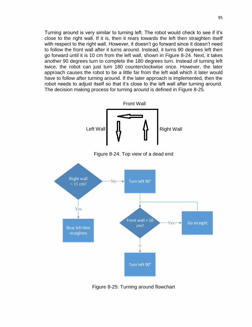
95
Turning around is very similar to turning left. The robot would check to see if it’s close to the right wall. If it is, then it rears towards the left then straighten itself with respect to the right wall. However, it doesn’t go forward since it doesn’t need to follow the front wall after it turns around. Instead, it turns 90 degrees left then go forward until it is 10 cm from the left wall, shown in Figure 8-24. Next, it takes another 90 degrees turn to complete the 180 degrees turn. Instead of turning left twice, the robot can just turn 180 counterclockwise once. However, the later approach causes the robot to be a little far from the left wall which it later would have to follow after turning around. If the later approach is implemented, then the robot needs to adjust itself so that it’s close to the left wall after turning around. The decision making process for turning around is defined in Figure 8-25.
Figure 8-24: Top view of a dead end
Figure 8-25: Turning around flowchart
Right wall
< 11 cm?
Rear left then
straighten
Turn left 90°
Go straight
Yes
No
Front wall > 10 cm?
Turn left 90°
Yes
No
Left Wall
Front Wall
Right Wall

96
8.6.1 Prototype Construction for Testing Before testing maze solving algorithm, the team received 3 PCBs manufactured from OSH Park. The team soldered all necessary surface mount components on the PCBs. The 3.3 V and 5 V regulation systems were both fully functional. However, the MSP430F5529 chip couldn’t be programmed using Spy-Bi-Wire. As a result, the PCBs were used to supply 3.3 V to an MSP430F5529 Launchpad and 5 V to the sensors and motors while robots were moving. Two wires, one is positive, the other is ground, of a battery holder which contains 4 battery cells were plugged into a breadboard. The breadboard also has a red LED in series with a 200 Ω resistor connected from the positive to the ground of the battery. The LED helps the team to know if the battery is on or off since the battery was placed below the chassis frame. Larger resistor values were used for the LED. However, the LED became dimmer as the value increases. Two 10 uF capacitors were also connected in parallel with the battery to filter out any DC noise from the battery. Next, the team connected all the grounds of the battery, PCB, and Launchpad. All signal pins from the sensors and servos were connected to the I/O pins of the Launchpad. Since the servos’ input voltage ranges from 4.8 V to 6 V and the battery was measured at around 5.5 V when fully charged, the motors’ power pin can be connected directly to the battery’s positive terminal instead of the 5 V regulator’s output. Since there’s no 3.3 V male header on the PCB, a green jumper wire was soldered directly to the output pin of the REG113-33 regulator, shown in Figure 8-26. The 3V3 label on the PCB is wrong. The label should be 5V instead of 3V3. All the male header pins in the top rectangle box are ground. All the male header pins in the bottom rectangle box are 5 V. To supply 5 V to the Launchpad, use a female-female jumper wire to connect one of the 5V pins on the PCB to one of the 5 V pins on the Launchpad. The jumper wire connected to 3.3 V output is plugged in one of the 3V3 pins on the Launchpad.
Figure 8-26: PCB used for testing

97
Figure 8-27 shows how the pins of the servos and sensors are connected to the I/O pins, 5 V pin, and GND pin on the Launchpad. When Serial Monitor is needed to debug a problem, the Launchpad is connected directly to a computer using a USB cable. The PCB can be disconnected from the Launchpad since the computer supplies 5V to the Launchpad which regulates 3.3 V to the MSP430F5529 chip on the Launchpad.
Servo and IR Sensor Connections
Pin Color Connected To
Red 5 V
Black Ground
White/Yellow Microcontroller analog or digital I/O pin
Figure 8-27: Servos and sensors pin connections
8.6.2 Navigation Problems and Solutions The team experienced countless problems while testing turning and maintain straight using sensors’ reading. Moving while avoiding obstacles was easier than correctly detecting a junction when one was present. Below are some of the problems that occurred while testing right-wall-following robot and the solutions. All the sensors on the robot are ultrasonic sensors.
Figure 8-28: Top view of a -| junction
Problem 1: Multiple Ss were stored when no -| junction was present, shown in
Figure 8-28. Solution 1: Count the number of times the robot detects a left opening. If the
number is less than 10, it is a false junction. If it’s equal to or greater than 10, then the robot correctly detects a -| junction and an S should be stored.
Ultrasonic Sensor Connections
Pin Name Connected To
Vcc 5 V
Trig Microcontroller digital or analog I/O pin
Echo Microcontroller analog I/O pin
GND Ground

98
Problem 2: Right sensor reading suddenly increased to a very high distance value. As a result, the robot incorrectly detected a right opening so it stored an R.
Solution 2a: For both left and right sensors, always compare the previous reading to the next one. If the readings differ by 10 cm, then take 10 reading samples and select the lowest value.
Solution 2b: The right sensor reading stays at a high value only for a short period of time while the robot navigates between two walls. When the robot is at a junction with a right opening, the reading stays high for a longer period of time. Therefore, if the right sensor reading stays high for 4 consecutive times, then there is actually a right opening.
Solution 2c: Replace the right ultrasonic sensor with an IR sensor, which less likely would falsely detect an opening than ultrasonic sensor. The team decided to combine solutions 2c and 2a to resolve the problem.
Problem 3: Sensor reading stayed relatively constant for a long period of time
while the robot moved. Solution 3: Tighten all sensors’ signal, ground, and 5 V connections.
8.7 Algorithm Implementation
8.7.1 Simplification In senior design 1, we planned to use encoders for the PID control. However, after researching, we decided not to use PID control. First of all, encoders are quite expensive. It can cost around 50 dollars or more. We were aiming for a low-cost robot so we were trying to make the cost as low as possible. It also adds to the complexity of hardware design. Secondly, it’s difficult to tune the PID constants. We have a total of 3 constants to tune, KP, KI, and KD. Tuning each constant takes a considerable amount of time and testing. Even with extensive testing, the PID control may not be perfect. We needed the PID control to help the robot maintaining a straight path. However, we found that we can also achieve a straight path if the robot moves forward while slight left and right. Even the path is not perfectly straight, the robot still maintains good distance from both walls. In conclusion, removing PID control saved us a lot of time and reduced the complexity of software design.
8.7.2 Solving the Maze Because the maze is quite small, we cannot let both robots run side by side. Therefore, in order for this to work, the robots start at the same location but at different time. We cannot allow one robot to go in front of the other either. If the robots see each other, they may mistake the other for a wall.
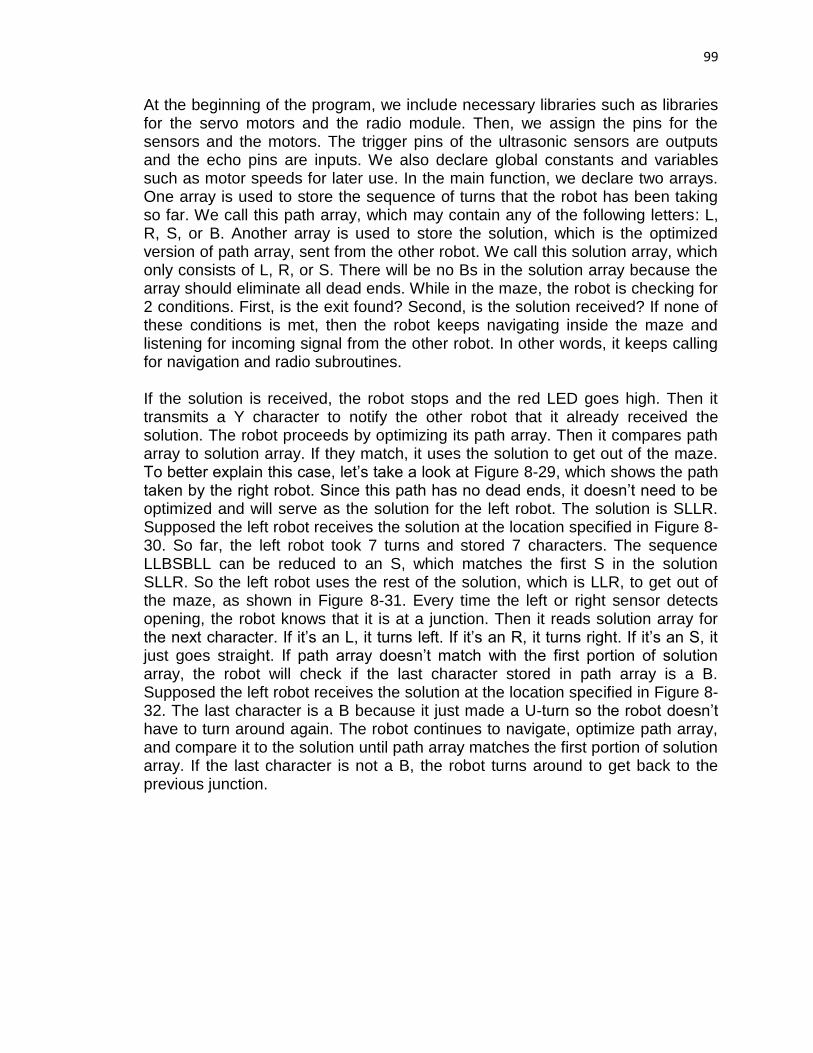
99
At the beginning of the program, we include necessary libraries such as libraries for the servo motors and the radio module. Then, we assign the pins for the sensors and the motors. The trigger pins of the ultrasonic sensors are outputs and the echo pins are inputs. We also declare global constants and variables such as motor speeds for later use. In the main function, we declare two arrays. One array is used to store the sequence of turns that the robot has been taking so far. We call this path array, which may contain any of the following letters: L, R, S, or B. Another array is used to store the solution, which is the optimized version of path array, sent from the other robot. We call this solution array, which only consists of L, R, or S. There will be no Bs in the solution array because the array should eliminate all dead ends. While in the maze, the robot is checking for 2 conditions. First, is the exit found? Second, is the solution received? If none of these conditions is met, then the robot keeps navigating inside the maze and listening for incoming signal from the other robot. In other words, it keeps calling for navigation and radio subroutines. If the solution is received, the robot stops and the red LED goes high. Then it transmits a Y character to notify the other robot that it already received the solution. The robot proceeds by optimizing its path array. Then it compares path array to solution array. If they match, it uses the solution to get out of the maze. To better explain this case, let’s take a look at Figure 8-29, which shows the path taken by the right robot. Since this path has no dead ends, it doesn’t need to be optimized and will serve as the solution for the left robot. The solution is SLLR. Supposed the left robot receives the solution at the location specified in Figure 8-30. So far, the left robot took 7 turns and stored 7 characters. The sequence LLBSBLL can be reduced to an S, which matches the first S in the solution SLLR. So the left robot uses the rest of the solution, which is LLR, to get out of the maze, as shown in Figure 8-31. Every time the left or right sensor detects opening, the robot knows that it is at a junction. Then it reads solution array for the next character. If it’s an L, it turns left. If it’s an R, it turns right. If it’s an S, it just goes straight. If path array doesn’t match with the first portion of solution array, the robot will check if the last character stored in path array is a B. Supposed the left robot receives the solution at the location specified in Figure 8-32. The last character is a B because it just made a U-turn so the robot doesn’t have to turn around again. The robot continues to navigate, optimize path array, and compare it to the solution until path array matches the first portion of solution array. If the last character is not a B, the robot turns around to get back to the previous junction.

100
Figure 8-29: Right robot follows the solution SLLR
Figure 8-30: Left robot receives solution after 7 turns
If the exit is found, the robot stops and optimizes its path array. Path array becomes the solution because after optimization, all Bs are discarded. Now, the path is a continuous line from the entrance to the exit without going through any dead ends. The robot then sends the solution to the slower robot which is still inside the maze. It keeps sending the solution until it receives a Y from the other robot. While it’s transmitting, the LED will be blinking. After receiving a Y, the robot stops transmitting and moves forward briefly to leave enough room for the slower robot when it arrives.
Each robot needs a navigation subroutine. However, left robot’s subroutine is slightly different from right robot’s subroutine since left robot prioritizes left turn and right robot prioritizes right turn. First, the robot reads from left, right, and front sensors. Then it compares sensor readings to 5 cases. For the left robot’s navigation, we have the following:
1. Left sensor detects opening? Yes – Turn left, store an L No – Go to the next case

101
2. Left and right sensors detect walls, front sensor detects opening? Yes – Maintain a straight path No – Go to the next case 3. Left sensor detects walls, right and front sensors detect opening? Yes – Go straight to pass the three-way junction, store an S No – Go to the next case 4. Left and front sensors detect walls, right sensor detects opening? Yes – Turn right, store an R No – Go to the next case 5. All three sensors detect walls? Yes – Turn around, store a B
Figure 8-31: After optimization, left robot uses solution to find the exit
Figure 8-32: Left robot receives solution after a U-turn
For the right robot, we compare the right sensor’s reading first: 1. Right sensor detects opening?
Yes – Turn right, store an R No – Go to the next case

102
2. Left and right sensors detect walls, front sensor detects opening? Yes – Maintain a straight path No – Go to the next case 3. Right sensor detects walls, left and front sensors detect opening? Yes – Go straight to pass the three-way junction, store an S No – Go to the next case 4. Right and front sensors detect walls, left sensor detects opening? Yes – Turn left, store an L No – Go to the next case 5. All three sensors detect walls? Yes – Turn around, store a B
We need to include another condition in the first case to check for the exit. For the left robot, before turning left, it moves forward a little and checks to see if there is a big opening in the front.
1. Left sensor detects opening? Yes – Move forward a little, read the front and right sensors Right and front sensors detect an opening >40 cm?
Yes – Read the front sensor as the front servo rotates 180 degrees Every time the front sensor detects an opening >90 cm, counts up from 0. If the counter >= 20, exit is found If not, turn left, store an L
Likewise, before turning right, the right robot will move forward a little and check to see if there is a big opening in the front. Figure 8-33 below shows the overview of the maze solving algorithm.
START
Solution Received?
NAVIGATE& STORE L,S,R,B
STOPMOTORS
OPTIMIZE PATH
COMPARE SOLUTION
Solution Matches?
FOLLOW SOLUTION
Exit Found?
SEND SOLUTION
END
NoNo
Yes
Yes
Yes
No
Figure 8-33: Maze-solving algorithm overview

103
8.7.3 Finding the Exit We came up with multiple methods to find the exit. From testing, we conclude that only the last one works best, even though it has its own flaws. The following methods are used for the left robot so we will speak in terms of left hand rule. Initially, we tried to use 555 timers to blink IR LEDs, which will be placed at the exit. However, this poses a lot of problems. First of all, the IR sensor’s readings deviate when the LEDs are blinking. The sensor reading also deviates while the robot is inside the maze. We don’t know if the readings change due to the common fluctuation or due to blinking. Secondly, the IR beam is very narrow, it may miss the blinking LEDs even if we make a row of IR LEDs. Therefore, using IR LEDs to mark the exit is not a good practice. We wrote the first exit condition when we still used IR sensor for the front. Exit is found if the left, right, and front sensors detect far distance. However, when the robot exited the maze, front IR sensor stayed around 10 cm. The IR sensor’s maximum working range is 30 cm. It was out of range so the sensor jumped to low readings. Then we replaced the front IR sensor with an ultrasonic sensor. We wrote the second method based on the behavior of the front and right sensors at the exit. We observed that at the exit, the front sensor tends to detect an opening greater than 50 cm. The right sensor tends to deviate a lot when it detects long distance. So we count the number of times the right readings deviate. If it deviates more than 20 times, it is an exit. However, this method doesn’t work well because it varies from sensor to sensor. The readings only deviate a lot for that specific right sensor. When we put in another ultrasonic sensor of the same model, the sensor was pretty stable at the exit. Therefore, the robot will think it’s still inside the maze. We wrote the third method based on the fact that when the robot is outside the maze, the sensor readings are the same as when it passes a three-way junction. When the robot exits the maze, the robot will see opening on the left. It’ll turn left. Then it’ll follow the outer wall for some time before it turns left at a corner. When it follows the wall, the left sensor sees wall but the right and front sensors see opening, just like when the robot detects a three-way junction. So we just count the number of times the robot detects a three-way junction. If it exceeds a certain threshold, then it’s the exit. Ideally, this method will work if we have stable sensors that do not need to retake reading every time it deviates. When the robot is outside of the maze, the right sensor detects very long distance which causes it to deviate a lot. It then retakes 15 samples of reading and keeps the lowest reading. Then it moves forward over a very short distance. The robot reads the sensors again and this time, the right sensor also deviates a lot so it retakes another 15 samples of reading. This repeats until the robot turns left at the next corner. When we tested this, the robot barely moved forward because it stopped frequently and for a long period of time. To travel the length of a wood block, or a

104
distance of 30 cm, the robot would take a few minutes. Clearly, this method is very inefficient in term of time. Finally, we came up with the last method. We attached another servo to the front sensor. The front sensor stays still most of the time while the robot navigates within the maze. Before the robot turns left, it’ll move forward a little. If the front and right sensors detect a distance greater than 40 cm, then the front servo rotates 180 degrees. The front sensor calculates distance while the servo is rotating. Every time the front sensor detects a distance greater than 90 cm, we count up from 0. If the counter is greater or equal to 20, exit is found. However, there is a problem. The front and right sensors detect a distance greater than 40 cm both at a four-way junction and the exit. How do we differentiate between these 2 cases? The answer is we can’t. So we have to eliminate all four-way junctions from our maze structure. If we use more stable and more accurate sensors, the algorithm can work better. However, this will be left for future improvements.
8.7.4 Resolving Communication Issues When we attached the booster pack on the MSP430 launch pad, we did not see any data being sent or received on the serial monitor. We found out later that we were using the pins reserved for the radio module. The Anaren booster pack uses pins 2.2, 3.0, 3.1, 3.2, 6.5, 3V3 pin, and ground pin. However, we attached the sensors and motors on some of the general input/output pins. So to avoid that problem, we reserved pins 2.2, 3.0, 3.1, 3.2, and 6.5 when using the booster pack. We only used the 3V3 and ground pins. We attached the booster pack on the PCB and used blinking LEDs to indicate whether the communication part was working. However, we did not see the LEDs blinking so we assumed that the PCB communication did not work. We thought we used the wrong syntax by passing in the arrays incorrectly or using an invalid type. It turned out that the problem was not the PCB but the LEDs. We just did not give enough delay to show visible blinking. Another problem with the communication is the timeout. By default, Energia passed a timeout of 1000 milliseconds, or 1 second, to the function Radio.receiverOn when listening for incoming signal. We used the same timeout during testing. What we found was a great delay in the robot’s response. For an example, when the robot detects a junction, it’s supposed to stop right away. However, with a one-second timeout, the robot stops only when it nearly passes the junction. Similarly, when the robot encounters a dead end, it’s supposed to stop about 10 cm away from the wall. However, with the timeout, the robot only stops after it hits the wall. After we reduced the timeout to 50 milliseconds, the response has been improved significantly.

105
Initially, we only transmitted the solution once. However, we realized that was a big mistake. When we tested the algorithm, we saw that none of the robots received anything from the other robot. We assumed that once the data is transmitted, it will be received. However, in reality, while the robot is navigating inside the maze, it has to do a lot of things like reading sensors, controlling motors, detecting junctions, and storing characters in an array. Most of the time is spent navigating so it doesn’t always listen for incoming signal. The radio module only listens for 50 milliseconds, so if the other robot does not transmit in this time frame, it will never receive the solution since the transmission only occurs once. To solve this problem, we put the transmission in a while loop. The transmission only stops when the slower robot sends an acknowledgement that it already received the solution.
9 Impact of Design Constraints Imposed by Applicable Standards
A quick review of the standards above shows that this project is not directly affected by many standards, however, it is subject to a few. The first standard that is relevant is IEC 61249-2-23 Ed. 1.0 b:2005 which is a standard that governs flammability characteristics of PCB materials. This is obviously important to the project since we employ two PCBs in our project, one for each robot. These boards must conform to this standard since they are built using industrial materials. The next two standards are used to set standards for RF communication in the ISM band; our project has wireless communication between 915 MHz and 928 MHz. Due to this fact the RF module we selected, the Anaren AIR module, conforms to the FCC standards listed as well as the ITU standard.
10 Project Operation In order to correctly operate the two robots, users need to follow the below instructions. It’s recommended to operate the robots indoors away from excessive sunlight. Outdoors light exposure may cause infrared sensor readings to become unstable.
10.1 Uploading Maze Solving Program
1. Download Energia IDE from the following website: http://energia.nu/download/
2. Download the Energia sketches LeftRobot.ino or RightRobot.ino 3. Open Energia IDE by double clicking on energia.exe. 4. Click File then click Open. 5. Browse for LeftRobot.ino or RightRobot.ino then click Open.

106
6. Plug the USB connector of the MSP430 Flash Emulation Tool (FET) into the USB port of the computer then plug the FET’s 14-pin JTAG connector into the 14-pin male header on the PCB.
7. To program the MSP430F5529 chip and power it using the FET, connect a female-female jumper wire from J2 to the 3.3 V pin, shown in Figure 10-1. Note: Make sure the battery that’s connected to the PCB is switched off. To program the MSP430F5529 chip and power it using the PCB’s power supply, connect a female-female jumper wire from J4 to the 3.3 V pin. Note: The battery which supplies power to the PCB needs to be switched on.
Figure 10-1: PCB component labeling
8. In Energia, click on Tools then Board. Select either LaunchPad wl msp430f5529 (16MHz) or LaunchPad wl msp430f5529 (25MHz).
9. Click on Upload button then wait until Done Uploading is shown on the red bar at the bottom of the IDE. Note: To open the Serial Monitor for debugging purposes, click on Tools then Serial Monitor or click on the magnify glass icon on the upper right corner of the IDE.
10. Unplug the JTAG connector from the PCB.
10.2 Add I/O Pins Not Recognized by Energia Energia IDE only recognizes the I/O pins available on the MSP430F5529 Launchpad. However, the PCB does include several pins not supported by the Launchpad. Figure 10-2 shows all the I/O pins on the PCB. Notice that P1.7,

107
P7.2, P7.1, P6.7, and P1.1 are not on the Launchpad and therefore is not recognized by Energia. In order for the programmer to recognize all the pins on the PCB, follow the below instructions.
A = P1.7 B = P1.6 C = P1.5 D = P1.4 E = P7.3 F = P7.2 G = P7.1 H = P7.0 I = P6.7 J = P1.1 K = P6.4 L = P1.2
M = P6.2 N = P6.3
Figure 10-2: Top view of I/O pins
1. Download Code Composer Studio (CCS) from http://www.ti.com/tool/CcStudio.
2. Click on CCS executable and follow instructions to install CCS. 3. Open CCS then click on File then Import then Energia 4. Select Energia Sketch then click Next> 5. Browse for LeftRobot.ino or RightRobot.ino 6. Under Device, select msp430 for Target and either LaunchPad wl
msp430f5529 (16MHz) or LaunchPad wl msp430f5529 (25MHz) for Board.
7. Click Finish 8. In Project Explorer, click on the arrow of the Energia sketch to expand 9. Expand Includes then expand the third folder which contains
pins_energia.h 10. Open pins_energia.h then scroll down until you see the variable
declaration section: static const uint8_t A0 = 23;
Pins dedicated for motors
Pins dedicated for IR sensors
Pins dedicated for ultrasonic sensors

108
… static const uint8_t P6_5 = 2;
11. Declare the I/O pins not available on the launchpad in the section 12. Click on Build and Debug to upload the program to MSP430F5529 chip
on the PCB.
10.3 Configure the Maze It’s important to follow the below guidelines when constructing a maze.
Construct the maze so that all the walls are connected to the outer wall.
The height of the pieces of woods or carton paper should be at least 20 cm.
The distance between two opposite walls should be at least 30 cm.
At a junction, two walls that are perpendicular to each other should be placed so that none of the edges stick out, shown in Figure 10-3.
The maze can be constructed from pieces of woods or carton paper.
Wrong
Wrong Correct
Correct
These walls
stick out
Figure 10-3: Top view of a four-way junction configuration
10.4 Robot Operation
1. Mount the Anaren AIR module onto the PCB as shown in Figure 10-4. If the module is not mounted or mounted on incorrectly, then the robot wouldn’t run.

109
Figure 10-4: Anaren AIR module mounting configuration
2. Switch the battery on. 3. If the front sensor doesn’t tilt clockwise, as shown in Figure 10-5b, then
proceed to the next step. If it does, then turn off the battery. Twist the front servo slightly in the counterclockwise direction, as shown in Figure 10-5c. Turn the battery on again. If the front sensor is at the center, as shown in Figure 10-5a, then proceed to the next step. If it’s still tilted, then repeat step 2 again until the sensor goes back to the center position.
Figure 10-5: Top view of front servo and sensor
(a) Center position
(b) Tilted clockwise
(c) Tilted counterclockwise

110
4. If the robot is right-wall-following robot, hold it about 10 cm from the right wall. If the robot is left-wall-following robot, hold it about 10 cm from the left wall.
5. Now release the robot to let it run. 6. To restart the robot, push the white reset button on the PCB.
10.5 Final Assembly Two servos for the wheels and the battery holder are placed at the bottom of the chassis frame. Since the chassis is metallic, the PCB is placed on an insulator or a plastic frame, which is mounted on three poles. The PCB has an LED to serve as a status indicator while path solution is transmitted and received. However, this LED is located below the Anaren AIR module and is not easily seen from the top. As a result, a larger red LED is used. The LED is connected in series with a resistor on a breadboard which is placed below the PCB as shown in Figure 10-6. On the left is the right-wall-following robot and on the right is the left-wall-following robot.
Figure 10-6: Actual models of twinbots
PCB
AIR module
IR sensor
Front servo
Ultrasonic sensor
LED and breadboard

111
11 Administrative Content
11.1 Team Management Once we decided on our project, we developed a timeline for our periodic meetings through the semester. We met up every week to report to other members what we were currently working on and shared some of the things we learned. We also assigned new tasks for the upcoming weeks. Our goal was to keep the project simple at first. As we researched more, we added improvements to the robot and changed our objectives if necessary. The first 3 months of Senior Design 1 were for research and purchasing components. The last month of Senior Design 1 was for prototyping and testing, as shown in Figure 11-1. We also wrote a report of 90 pages. As we researched, we wrote down what we learned in the report. We found out that writing everything down after all the research was done would take more time. When we created the table of content, we also assigned areas of specialty to each member, as shown in Figure 11-3. We collaborated on some parts as well.
Aug Sept Oct Nov Dec Documentation
Research Prototyping
Figure 11-1: Project timeline for Senior Design 1
Unlike Senior Design 1, we spent most of our time on prototyping, testing, and redesigning in Senior Design 2. We spent a few weeks designing the PCB layout. We had to wait for another week for the PCB to arrive. Then we spent a few days soldering the components. After we found out that the MSP430 microcontroller on the PCB could not be programmed, we had to redesign a new board. We spent approximately half of the semester on hardware design and another half on software design. It did not take much time to write the maze solving algorithm. However, we spent a lot of time on sensor testing and navigation. Figure 11-2 below shows the timeline of Senior Design 2.
Jan Feb Mar Apr Purchase components PCB layout, soldering, and troubleshooting Algorithm testing and troubleshooting Final system integration and testing
Documentation
Figure 11-2: Project timeline for Senior Design 2

112
Division of Tasks
Ly Nguyen Uyen Nguyen Luke Ireland
Motor testing Data processing Maze construction
PCB design Navigation PCB layout
System integration Maze-solving algorithm Soldering
Circuit troubleshooting Code testing
Bill of materials
Figure 11-3: Division of tasks
11.2 Senior Design 1 Project Milestone All of us are pretty new to this project since we did not have any experience in robotics. Ideally, we aim to prototype and test at the end of this semester. We overestimate the time needed to complete each task so that if an unexpected problem comes up, we still have enough time to fix. However, 80% of the time is already dedicated to research. We spent so much time on research because not all information we read about is related to what we are working on. Sometimes when we are building a part of the robot, we have to go back and research for more information. While doing our own research, we have to keep in mind the other members’ research too. For an example, if one member works on protection circuits and the other two are working on sensors and microcontroller, the first member has to keep in mind of the specifications of the sensors and microcontroller. The research part is very crucial. It eventually determines how our product will turn out. One wrong step can lead to a series of problems in the future. Therefore, we pay very particular attention to our research. Initially, we wanted to finish the research part as soon as possible so that we have more time on the designing and prototyping. However, we are slightly behind schedule. Nevertheless, we all have solid understanding of where we are heading so we can be on track pretty quickly. If necessary, we’ll spend more time on the project to speed things up. To increase productivity, we decide that each member should specialize in certain topics. This method saves time and prevents confusion due to overloaded information. Then we share what we learn with each other. However, we’ll collaborate on the designing, testing, and coding because they are too important to leave to one member. After we have finished a decent amount of research, we set out to acquire the components. We are looking for two factors: price and quality. For the sensors, the price is not too expensive so we should favor accuracy over price. For the microcontroller, we have to consider the price and the functionality such as the number of ports, the memory, and the processing power. Also, we need to know what kind of communication technology is compatible with that processor or Launchpad. So far, we have acquired some of the material and just started with prototyping. Connecting the components together won’t take too much time but getting them to work will take a lot of time. Interfacing the microcontroller with the

113
sensors and motors are important to the robot’s decision-making process. Therefore, this process will take a significant amount of time. We expect it to drag on for a few months. Figures 11-4a and 11-4b below show the milestone of the group. Aug 25
Sept 1 Sept 8
Establish Objectives
Form a group and start brainstorming
Group decides to do a robot project, start to research about different types of robot
Group decides to do a maze-solving robot, discuss about the goals of the project
Aug Sept Oct Nov Research
Research types of mazes
Research sensors
Research data analysis and sensor interpretation
Research microcontrollers
Research communication protocols & technology
Research IDEs and open-source software
Research motors and other mechanical components
Research protection circuits
Research PCB
Research system integration
Research algorithms Aug Sept Oct Nov Design
Design protection circuits Design PCB layout Simulate and capture schematics Design maze and develop test cases Create pseudocodes
Figure 11-4a: Project milestone

114
Aug Sept Oct Nov Acquisition of Material
Purchase sensors
Purchase connecting cables
Purchase regulators
Purchase motors
Purchase chassis
Purchase battery
Purchase PCB
Purchase microcontrollers
Purchase booster packs Sept Oct Nov Dec Prototyping & Testing
Integrate protection circuits with motors, sensors, and microcontroller
Interfacing sensors with microcontroller
Gather and analyze sensor data
Write a function for the output voltage
Test the accuracy of CPU data processing
Interfacing motors with battery
Interfacing motors with microcontroller
Write test codes to rotate motors clockwise and anti-clockwise
Test the number of pulses necessary to make 90° turn and 180° turn
Write conditions for decision-making process Aug Sept Oct Nov Documentation
Note all the advantages and disadvantages of all components
Note all the failures, fixes, and successes
Start on final report and divide the topics among team members
Write final report
Get together to finalize report
Group members read through the whole report to familiarize themselves with the entire system.
Group members decide the next step over winter break
Figure 11-4b: Project milestone

115
11.3 Budget and Financing Texas Instruments’ distributors Digi-key and Mouser have search filters that are simpler and easier to use than that of TI. Besides, the distributors allow buyers to select the mounting style which is not offered on Texas Instruments’ website. The team utilized the distributors’ search filter to find TI products. Since there might be a chance that a component might become defective or break during testing and prototyping, electronic components were purchased in multiple quantities. Nonetheless, the group kept the quantity at a reasonable level, since it may be expensive to buy at a large amount. Besides, the team might not use the leftover after Senior Design 2. In order to save on shipping costs, our team tried to purchase only from a few sellers. Our team first looked for the items at local stores where we could pick up. If the items were not available locally, then we looked for them in online stores. Figures 11-5 to 11-8 list all the components needed for building the robots. All of the cost come from the hardware. The software part is free. Some of the components are free such as the chassis, the launch pads, and the booster packs. The launch pads and booster packs were acquired from Texas Instruments’ $200 coupon. We also sampled regulators and microcontrollers for free. The chassis were donated from other people. If these components were not free, the cost would be much higher. We didn’t need the encoders so we save approximately $100 on encoders. Most of the cost come from the IR sensors, sensor cables, Digikey components, and radio modules.

116
Item Manufacturer Part Number Seller Quantity Price/Unit
IR Range Sensor Sharp Microelectronics GP2Y0A21YK0F Digi-Key 9 $7.40
Sensor Cable
RB-Onl-11 RobotShop 7 $1.95
805-28995 Digi-Key 1 $3.88
Ultrasonic Sensor
HC-SR04 Ebay 3 $2.99
HC-SR05 Ebay 2 $3.99
Sensor Bracket Lynxmotion RB-Lyn-75 RobotShop 1 $4.95
Continuous Rotation Servo Parallax 900-00008 Parallax 2 $13.99
RF Module Anaren
A110LR09A00GM Anaren 2 $12.25
Digi-Key 4 $17.33
4 Rechargeable AA NiMH Batteries and Charger Rayovac PS332-4B Best Buy 2 $14.99
Enclosed 4 AA Battery Holder With Switch 270-409 Radioshack 1 $1.99
Boost Converter Texas Instruments TPS61232DRCT Digi-Key 1 $3.42
Fuse Bel Fuse Inc 3JS 100-R Digi-Key 2 $0.36
Inductor Bourns Inc 5300-01-RC Digi-Key 2 $0.94
2WD Mini Round Double-Deck Chassis Ebay 1 $11.77
M/F Jumper Wires
PRT-12794 ROHS Sparkfun 1 $1.95
Ebay 1 $3.39
F/F Jumper Wires
PRT-12796 ROHS Sparkfun 1 $1.95
Ebay 1 $3.39
M/M Jumper Wires
PRT-12795 ROHS Sparkfun 1 $1.95
4-Pin F/F Jumper Wires Ebay 1 $8.00
Breadboard and Jumper Wires Ebay 1 $3.99
Boe-Bot/SumoBot Wheel & Tire Parallax 28109 Parallax 2 $3.99
Rubber Band Tires Parallax Parallax 1 $3.50
Figure 11-5: Cost of separate items
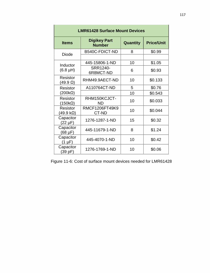
117
LMR61428 Surface Mount Devices
Items Digikey Part
Number Quantity Price/Unit
Diode B540C-FDICT-ND 8 $0.99
Inductor (6.8 µH)
445-15806-1-ND 10 $1.05
SRR1240-6R8MCT-ND
6 $0.93
Resistor (49.9 Ω)
RHM49.9AECT-ND 10 $0.133
Resistor (200kΩ)
A110764CT-ND 5 $0.76
10 $0.543
Resistor (150kΩ)
RHM150KCJCT-ND
10 $0.033
Resistor (49.9 kΩ)
RMCF1206FT49K9CT-ND
10 $0.044
Capacitor (22 µF)
1276-1287-1-ND 15 $0.32
Capacitor (68 µF)
445-11679-1-ND 8 $1.24
Capacitor (1 µF)
445-4070-1-ND 10 $0.42
Capacitor (39 pF)
1276-1769-1-ND 10 $0.06
Figure 11-6: Cost of surface mount devices needed for LMR61428

118
Miscellaneous Surface Mount Devices
Components Digikey Part
Number Quantity Price/Unit
Capacitor (0.1 µF) 1276-1506-1-
ND
25 $0.0308
Capacitor (10 µF) 490-10469-1-
ND
15 $0.095
445-7486-1-ND 15 $0.42
Resistor (1 kΩ) P16058CT-ND 20 $0.28
Capacitor (10 nF) 490-6340-1-ND 10 $0.028
Capacitor (4.7 µF) 490-3297-1-
ND
10 $0.08
Capacitor (470 nF) 490-3264-1-ND 10 $0.079
Resistor (0 Ω) RHM0.0ECT-
ND
25 $0.0292
Green LED 754-1121-1-ND 20 $0.117
Resistor (470 Ω) RHM470ADCT
-ND
30 $0.114
Crystal (32.768 kHz)
535-12058-1-ND
4 $1.06
Capacitor (12 pF) 490-6196-1-ND 10 $0.054
Capacitor (1 nF) 490-6189-1-ND 10 $0.147
Reset Button SW400-ND 7 $0.35
Male Header S1012E-36-ND 9 $1.57
Resistor (47 kΩ) P47.0KFCT-
ND
50 $0.0368
14-Pin Male JTAG Connector
A33161-ND 6 $1.39
Crystal (4 MHz) CSTCR4M00G
15L99
7 $0.70
Crystal (32.768 kHz)
MS3V-T1R 7 $0.45
Figure 11-7: Cost of miscellaneous surface mount devices

119
Item Cost ( Tax + Shipping Fee)
Woods $27.96
Velcro tape $4.79
Jumper wires (M/M, M/F, F/F) $24.72
Digikey order $223.07
13 ultrasonic sensors $22.85
7 IR sensor cables, 1 sensor bracket $37.44
2 wheels, rubber bands for wheels, 2 servos $43.04
1 chassis $12.74
2 breadboards $7.98
2 battery packs and chargers $31.94
3 battery holders $5.31
3 PCBs $37.85
2 crystals (4 MHz, 32.768 kHz) $13.04
6 radio modules $115.40
Total $608.13
Figure 11-8: Actual cost of materials
12 Conclusion The Maze Twinbots consists of two robots that communicate with each other to solve a maze. Our goal was to create robots to be small, cheap, and power-efficient. The robots are similar in functionality. Even though the team aimed to have consistencies in both robots, slight difference in hardware and software architecture may occur. Each robot has several key features: power management, wireless communication, mobility, and autonomous capability. The power management system includes the voltage regulator and battery. Wireless communication is implemented by using a radio module. Mobility is achieved by mechanisms of motors and wheels. Finally, autonomy is accomplished by integration of software libraries and custom codes which will be created by the team. During Senior Design 2, we spent significant amount of time debugging and troubleshooting software and hardware problems. Senior Design 1 was a research and designing phase. Some designing areas were lacking in Senior Design 1 but were fulfilled in Senior Design 2. The actual prototyping and testing was implemented in Senior Design 2. We have faced many obstacles in completing the project and have overcame them thank to our teamwork and cooperation.

I
References
[1] Robotics Universe, "Choosing a Motor: DC, Stepper, or Servo," [Online]. Available: http://robotoid.com/howto/choosing-a-motor-type.html. [Accessed 6 October 2014].
[2] Robotics Universe, "Understanding Motor Specifications," [Online]. Available: http://robotoid.com/howto/understanding-motor-specifications.html. [Accessed 6 October 2014].
[3] Robotzone, LLC. , "What Servo Do You Need?," ServoCity, [Online]. Available: https://www.servocity.com/html/what_servo_do_you_need_.html#.VH4S0DHF_JY. [Accessed 22 September 2014].
[4] Society of Robots, "Beginners: How to Build Your First Robot Tutorial," [Online]. Available: http://www.societyofrobots.com/robot_tutorial.shtml. [Accessed 2 October 2014].
[5] American National Standards Institute, "Home Page," 2014. [Online]. Available: www.nssn.org. [Accessed 29 April 2015].
[6] ModMyPi LTD, "What's the Difference between DC, Servo & Stepper Motors?," 25 August 2013. [Online]. Available: https://www.modmypi.com/blog/whats-the-difference-between-dc-servo-stepper-motors. [Accessed 2 October 2014].
[7] T. Igoe, "Lab: DC Motor Control Using an H-Bridge," 31 August 2014. [Online]. Available: https://itp.nyu.edu/physcomp/labs/motors-and-transistors/dc-motor-control-using-an-h-bridge/. [Accessed 15 September 2014].
[8] National Instruments Corporation, "Motor Fundamentals," 7 October 2014. [Online]. Available: http://www.ni.com/white-paper/3656/en/. [Accessed 19 November 2014].
[9] Baldor Electric Company, "Servo Control Facts," [Online]. Available: http://www.baldor.com/pdf/manuals/1205-394.pdf. [Accessed 9 October 2014].
[10] Society of Robots, "Actuators - Servos," [Online]. Available: http://www.societyofrobots.com/actuators_servos.shtml. [Accessed 1 October 2014].
[11] Blue Point Engineering LLC, "Servo Info and Centering," [Online]. Available: http://www.bpesolutions.com/atechnical/ServoInfo.Center.pdf. [Accessed 25 October 2014].
[12] A. Lindsay, "Activity 5: Centering the Servos," 29 February 2012. [Online]. Available: http://learn.parallax.com/node/185. [Accessed 11 September 2014].
[13] Jan, "Continuous-Rotation Servos and Multi-Turn Servos," 26 July 2011. [Online]. Available: http://www.pololu.com/blog/24/continuous-rotation-servos-and-multi-turn-

II
servos. [Accessed 2 October 2014].
[14] Anaheim Automation, "Encoder Guide," Anaheim Automation, 2011. [Online]. Available: http://www.anaheimautomation.com/manuals/forms/encoder-guide.php. [Accessed 1 November 2014].
[15] Camille Bauer, "KINAX 2W2-SSI Capacitive Absolute Encoder," [Online]. Available: http://www.gmc-camillebauer.com/pic/DM-2W2_SSI_KIN-WB__02-000405-3-L.pdf. [Accessed 1 November 2014].
[16] E. Eitel, "Basics of Rotary Encoders: Overview and New Technologies," 7 May 2014. [Online]. Available: http://machinedesign.com/sensors/basics-rotary-encoders-overview-and-new-technologies-0. [Accessed 2 November 2014].
[17] W. Storr, "io4a.gif," Positional Sensors, [Online]. Available: http://www.electronics-tutorials.ws/io/io_2.html. [Accessed 1 November 2014].
[18] K. Ross, "The Basics," [Online]. Available: http://www.seattlerobotics.org/encoder/mar97/basics.html. [Accessed 6 November 2014].
[19] Avago Technologies US Inc., "Quick Assembly Two and Three Channel Optical Encoders," 2014. [Online]. Available: http://www.avagotech.com/docs/AV02-1046EN. [Accessed 2 November 2014].
[20] "How Hall Effect Sensor Works," [Online]. Available: http://sensors-actuators-info.blogspot.com/2009/08/hall-effect-sensor.html. [Accessed 12 September 2014].
[21] AZoSensors, "Hall Effect Sensors," 3 August 2012. [Online]. Available: http://www.azosensors.com/article.aspx?ArticleID=16. [Accessed 13 September 2014].
[22] "How Capacitive Proximity Sensor Works," [Online]. Available: http://sensors-actuators-info.blogspot.com/2009/08/capacitive-proximity-sensor.html. [Accessed 12 September 2014].
[23] "How Inductive Proximity Sensor Works," [Online]. Available: http://sensors-actuators-info.blogspot.com/2009/08/inductive-proximity-sensor.html. [Accessed 12 September 2014].
[24] "How Ultrasonic Proximity Sensor Works," [Online]. Available: http://sensors-actuators-info.blogspot.com/2009/08/ultrasonic-proximity-sensor.html. [Accessed 12 September 2014].
[25] "How Photoelectric Proximity Sensor Works," [Online]. Available: http://sensors-actuators-info.blogspot.com/2009/08/photoelectric-proximity-sensor.html. [Accessed

III
12 September 2014].
[26] AutomationDirect, "Photoelectric Sensors," [Online]. Available: http://www.automationdirect.com/static/catalog/19-sensor-photoelectric-photo.pdf. [Accessed 13 September 2014].
[27] RS Components Ltd., "Raspbery Pi," 1 December 2014. [Online]. Available: http://uk.rs-online.com/web/generalDisplay.html?id=raspberrypi. [Accessed 1 December 2014].
[28] RobotShop Distribution Inc., "Wiring S Microcontroller Development Board," RobotShop, 3 November 2014. [Online]. Available: http://www.robotshop.com/en/wiring-s-microcontroller-development-board.html. [Accessed 1 December 2014].
[29] BeagleBoard.org, "BeagleBone Black," BeagleBone, 23 November 2014. [Online]. Available: http://beagleboard.org/black. [Accessed 1 December 2014].
[30] Parallax Inc., "Parallax Standard Servo (#900-00005)," 24 October 2011. [Online]. Available: http://www.parallax.com/sites/default/files/downloads/900-00005-Standard-Servo-Product-Documentation-v2.2.pdf. [Accessed 5 October 2014].
[31] Microchip Technology Inc., "dsPIC30F1010," Microchip Technology Inc., 12 October 2014. [Online]. Available: http://www.microchip.com/wwwproducts/Devices.aspx?product=dsPIC30F1010. [Accessed 1 December 2014].
[32] Texas Instruments, "Microcontrollers (MCU)," Texas Instruments, 27 November 2014. [Online]. Available: http://www.ti.com/lsds/ti/microcontrollers_16-bit_32-bit/msp/overview.page. [Accessed 1 December 2014].
[33] Battery University, "BU-303: Confusion with Voltages," [Online]. Available: http://batteryuniversity.com/learn/article/confusion_with_voltages. [Accessed 5 November 2014].
[34] Dimension Engineering LLC, "A Beginner's Guide to Switching Regulators," [Online]. Available: https://www.dimensionengineering.com/info/switching-regulators. [Accessed 8 September 2014].
[35] Silicon Labs Inc., "Key Priorities for Sub-GHz Wireless Deployment," Silicon Labs Inc., 4 June 2012. [Online]. Available: silabs.com. [Accessed 1 December 2014].
[36] Anaren, "Products," Anaren, January 2014. [Online]. Available: https://www.anaren.com/search/node/A110LR09A. [Accessed 1 December 2014].
[37] W. D. Pullen, "Maze Classification," 1 November 2014. [Online]. Available:

IV
http://www.astrolog.org/labyrnth/algrithm.htm. [Accessed 10 September 2014].
[38] Society of Robots, "Basic Electronics Components," [Online]. Available: http://www.societyofrobots.com/electronics_basic_components_tutorial.shtml . [Accessed 2 October 2014].
[39] Society of Robots, "Schematics - Robot Power Regulation," [Online]. Available: http://www.societyofrobots.com/schematics_powerregulation.shtml. [Accessed 2 October 2014].
[40] OddBot, "Once You've Decided on Batteries, How Do You Regulate the Voltage?," 9 December 2008. [Online]. Available: http://letsmakerobots.com/content/once-youve-decided-batteries-how-do-you-regulate-voltage?page=6. [Accessed 17 October 2014].
[41] Society of Robots , "The $50 Robot," [Online]. Available: http://www.societyofrobots.com/step_by_step_robot_step3A.shtml. [Accessed 19 October 2014].
[42] Littelfuse, Inc. , "FAQs," [Online]. Available: http://www.littelfuse.com/technical-resources/faqs/fuse-ratings.aspx. [Accessed 13 November 2014].
[43] B. Perrett, "Fuses, What and Why.," [Online]. Available: http://highfields-arc.co.uk/constructors/info/fuses.htm. [Accessed 25 October 2014].
[44] Future Electronics, "What Is a Schottky Diode?," [Online]. Available: http://www.futureelectronics.com/en/diodes/schottky-diodes.aspx. [Accessed 18 September 2014].
[45] K. Wu, "Introduction to Schottky Rectifier and Application Guidelines," [Online]. Available: http://www.farnell.com/datasheets/312532.pdf. [Accessed 20 September 2014].
[46] Society of Robots, "LED Tutorial," [Online]. Available: http://www.societyofrobots.com/electronics_led_tutorial.shtml. [Accessed 3 October 2014].
[47] Sharp Microelectronics, "Analog Output Type Distance Measuring Sensor," 5 March 2007. [Online]. Available: http://media.digikey.com/pdf/Data%20Sheets/Sharp%20PDFs/GP2Y0A41SK0F_Spec.pdf. [Accessed 25 October 2014].
[48] R. T. Vannoy II, "Design a Line Maze Solving Robot," April 2009. [Online]. Available: http://www.pololu.com/file/0J195/line-maze-algorithm.pdf. [Accessed 27 October 2014].
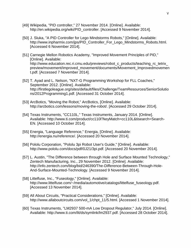
V
[49] Wikipedia, "PID controller," 27 November 2014. [Online]. Available: http://en.wikipedia.org/wiki/PID_controller. [Accessed 9 November 2014].
[50] J. Sluka, "A PID Controller for Lego Mindstorms Robots," [Online]. Available: http://www.inpharmix.com/jps/PID_Controller_For_Lego_Mindstorms_Robots.html. [Accessed 6 November 2014].
[51] Carnegie Mellon Robotics Academy, "Improved Movement Principles of PID," [Online]. Available: http://www.education.rec.ri.cmu.edu/previews/robot_c_products/teaching_rc_tetrix_preview/movement/improved_movement/documents/Movement_Improvedmovement.pdf. [Accessed 7 November 2014].
[52] T. Ayad and L. Nelson, "NXT-G Programming Workshop for FLL Coaches," September 2012. [Online]. Available: http://firstlegoleague.org/sites/default/files/Challenge/TeamResources/SeniorSolutions/2012Programming1.pdf. [Accessed 31 October 2014].
[53] ArcBotics, "Moving the Robot," ArcBotics, [Online]. Available: http://arcbotics.com/lessons/moving-the-robot/. [Accessed 29 October 2014].
[54] Texas Instruments, "CC110L," Texas Instruments, January 2014. [Online]. Available: http://www.ti.com/product/cc110l?keyMatch=cc110L&tisearch=Search-EN. [Accessed 10 October 2014].
[55] Energia, "Language Reference," Energia, [Online]. Available: http://energia.nu/reference/. [Accessed 20 November 2014].
[56] Pololu Corporation, "Pololu 3pi Robot User's Guide," [Online]. Available: http://www.pololu.com/docs/pdf/0J21/3pi.pdf. [Accessed 20 November 2014].
[57] L. Austin, "The Difference between through Hole and Surface Mounted Technology," Zentech Manufacturing, Inc., 29 November 2012. [Online]. Available: http://info.zentech.com/blog/bid/246390/The-Difference-Between-Through-Hole-And-Surface-Mounted-Technology. [Accessed 9 November 2014].
[58] Littelfuse, Inc., "Fuseology," [Online]. Available: http://www.littelfuse.com/~/media/automotive/catalogs/littelfuse_fuseology.pdf. [Accessed 13 November 2014].
[59] All About Circuits, "Practical Considerations," [Online]. Available: http://www.allaboutcircuits.com/vol_1/chpt_11/5.html. [Accessed 1 November 2014].
[60] Texas Instruments, "LM2937 500-mA Low Dropout Regulator," July 2014. [Online]. Available: http://www.ti.com/lit/ds/symlink/lm2937.pdf. [Accessed 28 October 2014].

VI
[61] Texas Instruments, "TPS6123x High Efficiency Synchronous Step Up Converters with 5-A Switches," October 2014. [Online]. Available: http://www.ti.com/lit/ds/symlink/tps61232.pdf. [Accessed 1 November 2014].
[62] Texas Instruments, "High Input Voltage Buck-Boost Converter with 2A Switch Current," February 2012. [Online]. Available: http://www.ti.com/lit/ds/symlink/tps63061.pdf. [Accessed 1 November 2014].
[63] Society of Robots, "Actuators - How to Modify a Servo," [Online]. Available: http://www.societyofrobots.com/actuators_modifyservo.shtml . [Accessed 1 October 2014].
[64] Society of Robots, "Robot Sensor Interpretation," [Online]. Available: http://www.societyofrobots.com/sensors_interpret.shtml. [Accessed 3 October 2014].
[65] Acroname, "Linearizing Sharp Ranger Data," Acroname, [Online]. Available: http://www.acroname.com/articles/linearizing-sharp-ranger.html. [Accessed 11 October 2014].

VII
Appendices
Appendix A Bibliography
Luke Ireland is currently a senior at the University of Central Florida and will be graduating with his B.S.E.E. in the top 5 percent (Magna Cum Laude) of his class in May 2015. Luke has accepted a position as a Test Engineer at Intersil Corporation in Palm Bay, Florida beginning May 11, 2015. He plans to take one year off and then return to earn his M.S.E.E specializing in semiconductor electronics from UCF as a part time student.
Ly Nguyen is currently a senior at University of Central Florida and will be graduating in May 2015. She plans to pursue master degree in robotics while working for NASA at Kennedy Space Center as an electrical engineer.
Uyen Nguyen is currently a senior at University of Central Florida and will be graduating in May 2015. She plans to pursue master degree in analog or digital circuit design.

VIII
Appendix B Copyright Permissions
Digi-Key
ElectronicsTutorials
Texas Instruments

IX
Anaren From: Geoffrey Cohler <[email protected]> Sent: Tuesday, December 02, 2014 7:43 PM To: Luke Ireland Subject: RE: Copyright Permission Hi, Please just cite the diagram, as coming from our manual and that is fine. Thanks very much for asking. And good luck on your project. Best regards, Geof
Geoffrey L. Cohler Manager, Americas Sales Anaren Microwave, Inc.
+1 (781) 218-9250 [email protected]
skype:geof.cohler

X
Links: www.anaren.com/air www.anaren.com/airsupport www.facebook.com/anareninc www.linkedin.com/in/gcohler
From: Luke Ireland [mailto:[email protected]] Sent: Tuesday, December 02, 2014 5:03 PM To: AIR Subject: Copyright Permission To whom it may concern, My name is Luke Ireland, I am an Electrical Engineering Student at the University of Central Florida. I am currently in the middle of my senior design project (Group 28); in this course we are required to submit a technical document that details the project design. I will be using a set of Anaren A110LR09A modules in my project, I am to ask for written permission to include a diagram for the PCB mounting procedures and the AIR module itself from the A110LR) 9x user manual with release date of 10/31/2011. Thank you for your time, Luke Ireland