Embed Size (px)
Citation preview
MAZAR HYDROELECTRIC POWER PLANT page 1 of 3
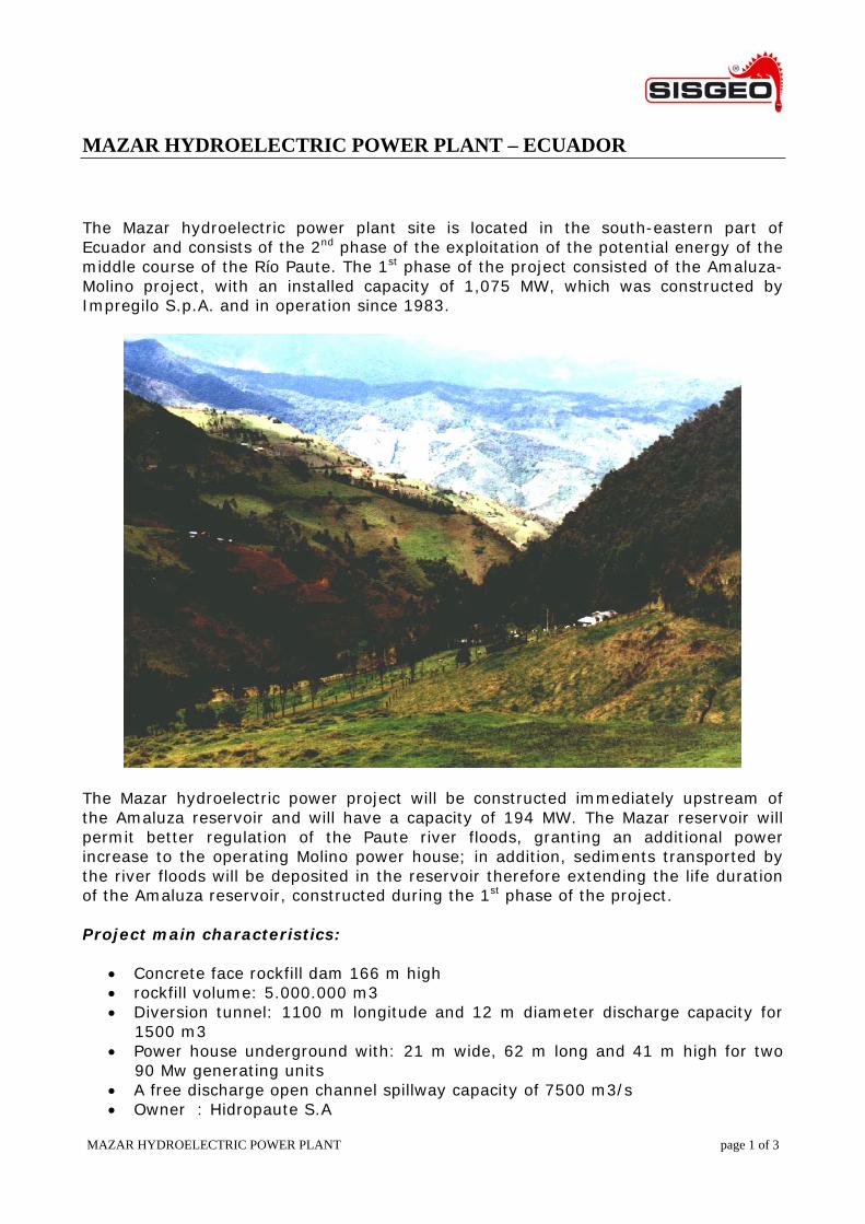
MAZAR HYDROELECTRIC POWER PLANT – ECUADOR The Mazar hydroelectric power plant site is located in the south-eastern part of Ecuador and consists of the 2nd phase of the exploitation of the potential energy of the middle course of the Río Paute. The 1st phase of the project consisted of the Amaluza-Molino project, with an installed capacity of 1,075 MW, which was constructed by Impregilo S.p.A. and in operation since 1983.
The Mazar hydroelectric power project will be constructed immediately upstream of the Amaluza reservoir and will have a capacity of 194 MW. The Mazar reservoir will permit better regulation of the Paute river floods, granting an additional power increase to the operating Molino power house; in addition, sediments transported by the river floods will be deposited in the reservoir therefore extending the life duration of the Amaluza reservoir, constructed during the 1st phase of the project. Project main characteristics:
• Concrete face rockfill dam 166 m high • rockfill volume: 5.000.000 m3 • Diversion tunnel: 1100 m longitude and 12 m diameter discharge capacity for
1500 m3 • Power house underground with: 21 m wide, 62 m long and 41 m high for two
90 Mw generating units • A free discharge open channel spillway capacity of 7500 m3/s • Owner : Hidropaute S.A
MAZAR HYDROELECTRIC POWER PLANT page 2 of 3
• Design and Supervision: Consortium formed by Leme (Brazil), Caminosca (Ecuador), Coyne et Bellier (France) and MN (Chile)
• Construction: Consortium formed by Impregillo Italia, Herdoiza Crespo (Ecuador)
• Electro mechanical equipment: Consortium formed by Alstom (France), Voith Siemens (Germany), Siemens (Colombia) and Santos CMI (Ecuador)
According to the configuration of the dam due to the asymmetric canyon, Mazar with a characteristic value A/H2 of 1.7 where A is the area of concrete face and H is the height of the dam, the Mazar Project was designed with a specific study. Numeric analysis (3D model) has been used to determinate the stresses and deformation generated in the rockfill and the concrete face that resulted in some aspects adopted in Mazar such as:
• Adoption of 7,5m wide slabs in the vertical compression zone determined with numeric analysis. The remaining slabs with 15 wide. Slab thickness variable according to 30+0,003Hm
• Adoption of 3,2cm spaces in the vertical compression joints of the concrete face to prevent the development of high stress on the concrete face
• Reinforcement of the concrete face equivalent to 0,5% in both directions with curtain reinforcement in the stress area
• Adoption of rockfill layers maximum thickness, after compaction, of 50 cm for zone 3B and 80 cm for the zone 3C and compacted after a least 6 passes of a 13,6 ton vibratory compactor
• Application of water while placing and compacting rockfill in an equivalent volume of 300l/m3
• Adoption of a vertical drain between zones 3B and 3C well-graded from 0.20m to 0.80m
• Installation of four sections with 80 electro levels to assess behavior of the slabs during and after the reservoir impounding.
The dam has two separate spillways with a total discharge capacity of 7,500 m³/s, one controlled by a free fall weir and the other by a crest radial gate (15m wide and 13m high). It also has a bottom outlet consisting of a 403m long concrete lined tunnel. Dam and related structures The dam is a concrete faced rockfill dam, 183 m high from its foundations, with a total volume of more than 5,000,000 cum. To link the face to the foundation of the dam, a 5 m wide steel reinforced concrete plinth will be constructed. The plinth foundation is consolidated as well as waterproofed by cement grout curtain up to a depth of approx. 60 m. For the dam construction the river will be diverted trough a 1,241 m long, 12m x 12m cross section diversion tunnel, partially concrete lined. The upstream cofferdam will be 35 m high.
MAZAR HYDROELECTRIC POWER PLANT page 3 of 3
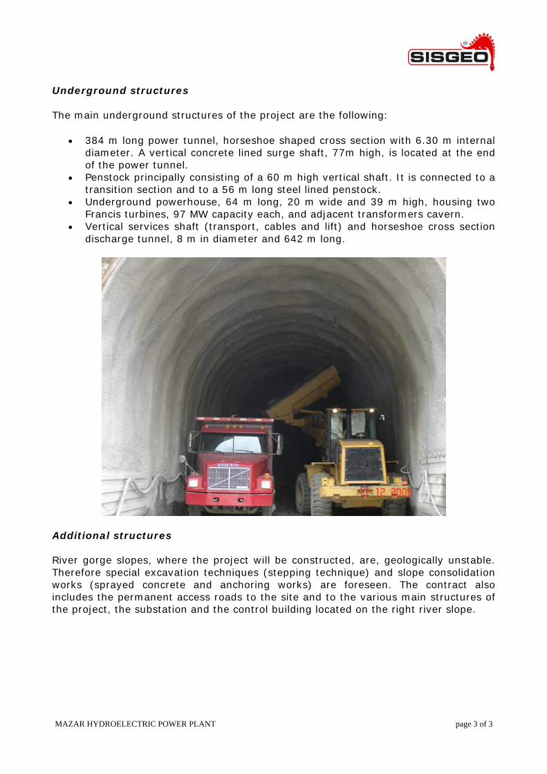
Underground structures The main underground structures of the project are the following:
• 384 m long power tunnel, horseshoe shaped cross section with 6.30 m internal diameter. A vertical concrete lined surge shaft, 77m high, is located at the end of the power tunnel.
• Penstock principally consisting of a 60 m high vertical shaft. It is connected to a transition section and to a 56 m long steel lined penstock.
• Underground powerhouse, 64 m long, 20 m wide and 39 m high, housing two Francis turbines, 97 MW capacity each, and adjacent transformers cavern.
• Vertical services shaft (transport, cables and lift) and horseshoe cross section discharge tunnel, 8 m in diameter and 642 m long.
Additional structures River gorge slopes, where the project will be constructed, are, geologically unstable. Therefore special excavation techniques (stepping technique) and slope consolidation works (sprayed concrete and anchoring works) are foreseen. The contract also includes the permanent access roads to the site and to the various main structures of the project, the substation and the control building located on the right river slope.