Embed Size (px)
Citation preview
Mayle, 1939. R. H, GODDÁRD _ ' 2,158,180 `
GYROSCOPIC STEERING APPARATUS
>Fnéd Nov. 9, 193e 3 sheets-sheet 1
May 16', 1939'. ' ' R. H. GòDDARD 2,151,8,180' GYROSCOPIC >S'I'I‘JI‘BRING APPARATUS
Filed Nov. 9, 1936 ' 5 Sheets-Sheet 2
a4 \ 111: < es
v////////
May' 16, I1939. « |=z.ß H. GODDARD I _ 2,158,180
GYROSCOPIC STEERING APPARATUS'
Filed Nov. 9, '1936 3 Sheets-Sheet 5
s 55 thereof;
Patented May 16, 1.9_39
_ #UNITI-:D STATES 2,158,180
‘ 2,158,180
PATENT OFFICE y GYROSCOPIC STEERING APPARATUS
Robert H. Goddard, Boswell, N. Mex. ApplicationNovember 9, 1936, Serial’No. 109,964
5 Claims.
, This invention relates to means for steering or directing theflightgof aircraft such as rockets, rocket planes, airplanes or dirigibles. _
It is the general object of my invention to pro > 5 vide gyroscopic steering apparatus for such air
craft, which may _be entirely enclosed within the craft and which embodies no wings, vanes y or other devices projecting outward into thesur rounding air or slip stream or into a rocket blast.
improved steering means for aircraft which will be operative regardless of the density of the air through which the craft is moving. _ To the attainment of these and other objects,
15 my invention relates to improved gyroscopic steering apparatus for directing the Hight of air craft, and to improved control mechanism, pref erably gyroscopíc, for said steering apparatus. My invention further relates to arrangements
20 and combinations of parts which will be herein after described» and more particularly pointed ’ out in the appended claims. ‘ _ A preferred form of the invention is shown in the drawings, in-which l .
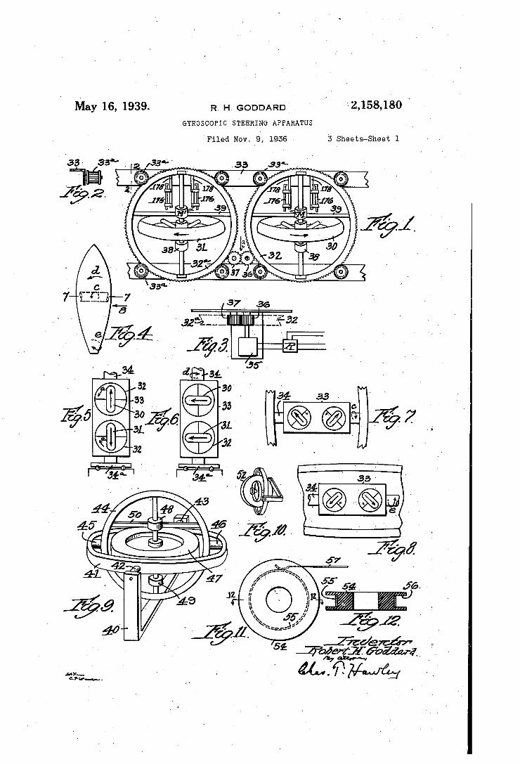
_ Fig. 1 isa perspective'view of a gyroscopic .steeringunit; T_ ' . ' ,
_ Fig. 2 is a detail sectional view, taken along the line 2-2 in Fig. 1; ,
Fig. 3 is` a detail plan view, looking in the di- 30 rection of the arrow 3 in Fig. 1;
~ Fig. 4 is a diagrammatic view ol'- an aircraft; Figs. 5 and 6 are diagrammatic views illustrat
ing the operation of the gyroscopic steering unit which controls the direction of iilght in a hori
35 zontal plane, as indicated by the arrow d in F18. 44 ‘ '
Fig. 7 1s a.`I sectional' view, taken along the une » 1_-1 in Fig. 4 andv showing the gyroscopic'steer ing unit which controls the tilting of the craft
40 in a vertical plane, as indicated by the 'arrow
Fig. 8 is a'side'elevation looking in the ldirec tion _of the arrow 8 in Fig.- 4, and shows s. gyro
‘ scopic steering unit 'for controlling rotation of an 45 aircraft aboutits longitudinal axis, as indicated
by the arrow e in Fig. 4; Fig. 9 is a perspective view of a double-acting
pilot gyroscope automatically controlling two gy roscopic steering units, such as the units which
50 control the vertical tilting of the craft and the direct-ion thereof in a horizontal plane;y
Fig. 10 is a perspective view of a second pilot` gyroscope eil’ective to controlangular displace mentof the craft around the longitudinal axis
1
A further object of the invention is'to provide `
(ci. 24a-asl' Fig. 11 is a view of a commutator for one of
the gimbal shafts of a pilot gyroscope; ` Fig. 12 is a detail sectional view, taken along
the line I2-I2 in Fig. 1l; . _ '
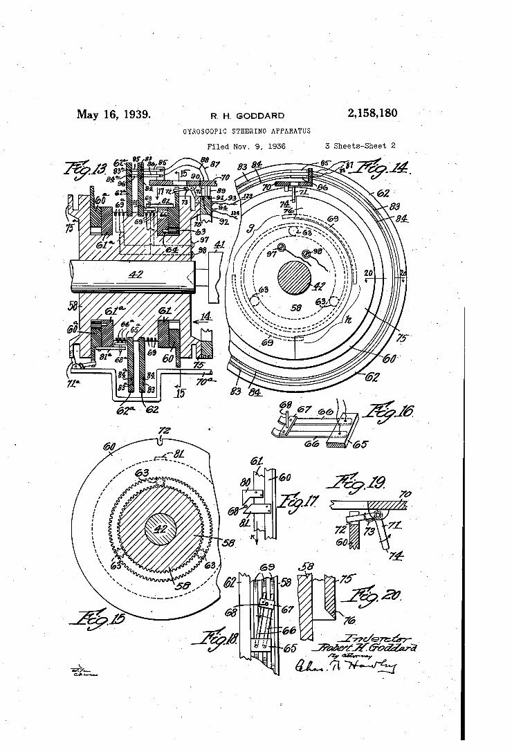
. Fig. 13 is a sectional elevation of a special ro tary switch for a pilot g'yroscope;
Fig. 14 is an end view thereof, partly in sec tion, -looking in the direction of the arrow I4 ' in Fig. 13; „, 1
Fig._15 is a sectional end elevation, taken along ¿the line |5-i5 in Fig. 13; I ‘
Fig. 16 is av perspective view of a reversing switch element; . - “ ' '
Fig.' 17 is a detail View of certain starting switch control parts, loolnng in the direction of the arrowl‘l in Fig. 13; _ Fig. 18 is`a plan View of the reversing switch,
with associated parts in operative relation; ' Fig. 19 is an enlarged side elevation of a locking> device ;_ « ' l, ~ ,
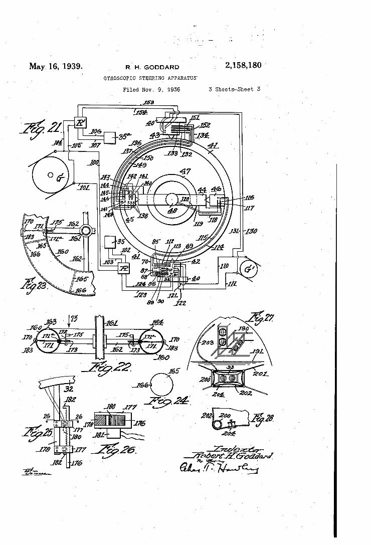
Fig. 20 is a detail séctionalsview, taken >along the line 20--26 in Fig. 14; ' Fig-2l is a. wiring diagram for one of the pilot
gyroscopes; _ '
_ Fig. 22 is a sectional view of a preferred form of rotating gyroscope element;
Fig. 23 is a partial plan view, looking in direction of the arrow 23 in Fig. 22; ” -
Fig. 24 isa. side elevation of a partition mem ber used in the gyroscope construction shown\ in Figs. 22 and 23; y ' '
Fig. 25 is a side elevation of certain valve .con trol mechanism;
the
Fig. 26 is an enlarged sectional view, taken ' along the line 26-26 in Fig. 25;
Fig. 27 is a diagrammatic view illustrating one - form of installation of my improved gyroscopic steering apparatus; and .
Fig. 28 is an enlarged detail sectional view to be described. ~ '
_In the development of my improved steering apparatus, I make usevof the known- principle that a. heavy ring rotating in a plane perpendicu lar to the axis oil a supporting structure will pro duce a reacting force tending to rotate the sup porting structure. which rotation will actually take place if the supporting structure is itself mounted ior free rotation. . _ l
_This principle, while previously f known, has not _- been directly adaptable to the control of aircraft,'as a rotating ring of sumcient mass to ~be eiîective' would react undesirably and irregu larly with any outside force acting on the craft,
. due to the gyroscopic ̀ force of the heavy rotating
15
40
45
50
55
35
5
10
"15
20
25
30
35
40
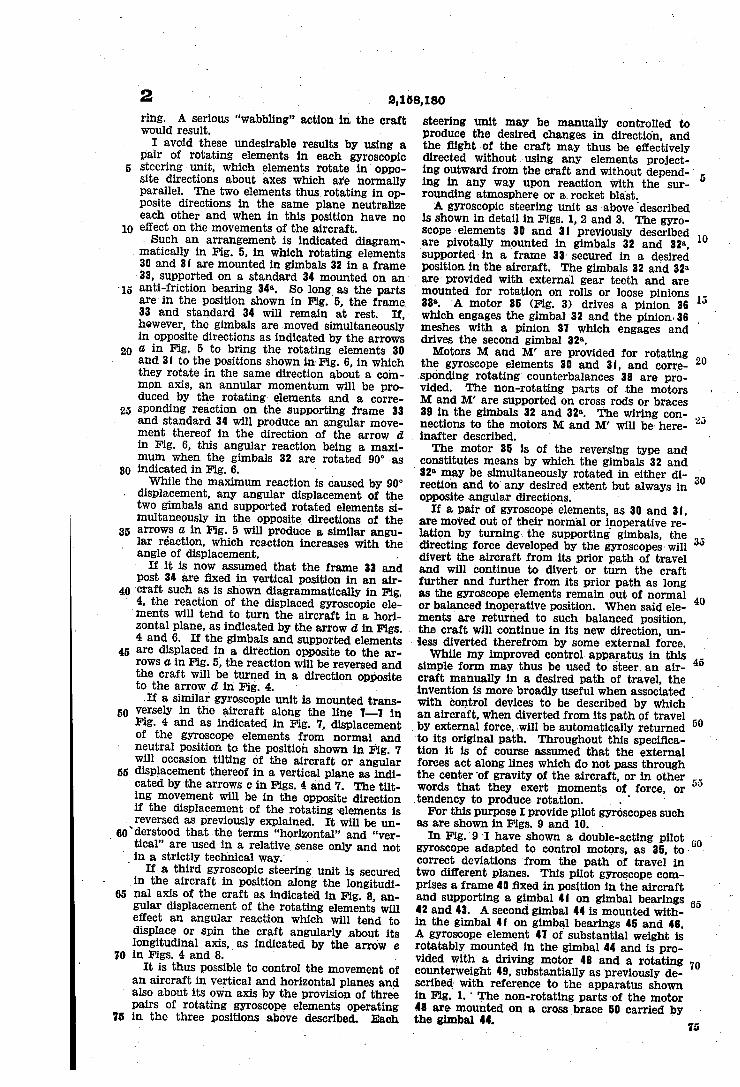
2 ring. A serious “wabb1ing" action in. the craft would result. "
I avoid these undesirable results by using a pair of rotating elements in each gyroscopic steering'unit, which elements rotate inY oppo site directions about axes which are normally parallel. The two elements thusl rotating in op posite directions in the same plane. neutralize each other and when in this position have no effect on the movements of the aircraft.
Such an arrangement is indicated diagram matically in Fig. 5, in which rotating elements 30 and 3| are mounted in gimbals 32 in a frame y33, supported on a standard 34 mounted on an anti-friction bearing 34°. So long as the parts are'in the position shown in Fig. 5. the frame, 33 and standard 34 will remain at rest. however, the gimbals are moved simultaneously in opposite directions as indicated by the arrows a in Fig. 5 to bring the rotating elements .30 and 3| to the positions shown im Fig. 6, in which they rotate in the same direction about a com mon axis, an annular momentum will be pro duced by the rotating elements and a corre sponding reaction onthe supporting frame 33 and standard 34 will produce an angular move ment thereof in the direction of the arrow d in Fig. 6, this angular reaction being a maxi mum when the gimbals 32 are rotated 90° as indicated in Fig. 6. ' While the maximum reaction is caused by 90°
displacement, any angular displacement of the two gimbals and supported rotated elements si multaneously in the opposite directions of the arrows a in Fig. 5 will produce a similar angu lar réaction, which reaction increases with the angle of displacement. .
If it is now assumed that the frame 33 and post 34 are ñxed in vertical position in an air craft such as is shown diagrammatically in Fig.
` 4, the reaction of the displaced gyroscopic ele
45
50
55
ments will tend to turn the aircraft in a horl zontal plane, as indicated by the arrow d in Figs. . 4 and 6. If the gimbals and supported elements are displaced in a direction opposite to the ar rows a in Fig. 5, the reaction will be reversed and the craft will be turned in a direction opposite _ to the arrow d in Fig. 4. ' ` »
.If a similar gyroscopic unit is mounted trans versely in the aircraft along the line ‘|-1 in Fig. 4 and as indicated in Fig. 7, displacement of the gyroscope elements from normal and neutral position to the position shown in Fig. 'I will occasion tilting of the aircraft or angular displacement thereof in a vertical plane as indi cated bythe arrows c in Figs. 4 and 7. The tilt ing movement will be in the opposite direction if the displacement of the rotating elements is
. reversed as previously explained. It will be un
_60
65
70
75
`>derstood that the terms “horizontal” and “ver tical” are used in a relative sense only and not
i in a strictly technical way.` .
If a third gyroscopic steering unit is secured vin the aircraft in position along the longitudi nal axis of the craft as indicated in Fig. 8, an gular displacement of the rotating elements will effect an angular reaction which will tend to displace or spin the craft angularly about its longitudinal axis,V as indicated by the arrow e in Figs. 4 and 8. .
It is thus possible to control the movement of an aircraft in vertical and horizontal planes and also about its own axis by the provision of three pairs of rotating gyroscope elements operating in the three positions. above described. Each
2,158,180 .
. steering unit may be manually _controlled to produce the desired changes in direction, and the ñight >of the craft may thus be effectively directed without using any elements project- » ing outward from the craft and without depend- ' ing in any way upon reaction with the sur rounding atmosphere or a rocket blast. A gyroscopic steering’unit as vabove described
is shown in detail in Figs. 1, 2 and 3. The gyro scope »elements 30 and 3| previously described are pivotally mounted in gimbals 32 and 32'“, supported in a frame 33' secured in a desired position in the aircraft. The gimbals 32 and 32a are provided with external gear teeth and are mounted for rotation on rolls or loose pinions 33B. 'A motor 35 (Fig. 3) drives a pinion 36
10
which engages the gimbal 32 and the pinion. 36 ~ meshes with a pinion 31 which engages and drives the second gimbal 32B. Motors M and M’ are provided for rotating `
the gyroscope elements 30 and 3|, and corre sponding rotating counterbalances 38 are pro vided. The non-rotating parts of the motors M and M' are supported on cross rods or braces 38 in the gimbals 32 and 32a. The wiring con nections to the motors M and M’ will be here inafter described. The motor 35 is of the reversing type and
constitutes means by which the gimbals 32 and ` 32ß may be simultaneously rotated in either di rection and to any desired extent opposite 4angular directions.
If a pair of gyroscope elements, as 30 and 3|, are moved out of their normal or inoperative re lation by turning the supporting gimbals, the directing force developed by the g'yroscopes‘will divert the aircraft from its prior path of travel and will continue to divert or turn the craft further and further from its prior path as long as the gyroscope elements remain _out of normal or balanced inoperative position. When said ele ments are returned to such balanced position, the craft will continue in its new direction, un
but always in
« `less diverted therefrom by some external force. While my improved control apparatus in this
simple form may thus be used to steer` an air craft manually in a desired path of travel, the
20
40
invention is more broadly useful .when associated ì with control devices to be described by which an aircraft, when diverted from its path of travel
v by external force, 4will be automatically returned to its original path. Throughout this specifica
, tion it is of course assumed that the external forces act along lines which do not pass through the center 'of gravity of the aircraft, or in other words that they exert moments of force, or tendency to produce rotation. . ° '
For this purpose I provide pilot gyroscopes such as are shown in Figs. 9 and 10. In Fig.`9 ̀ I have shown a double-acting pilot
gyroscope adapted to control motors, as 35, to correct deviations from the path of travel Yin two different planes. This pilot gyroscope com prises a frame 40 fixed in position in the aircraft and supporting a gimbal 4| ‘ on gimbal bearings 42 and 43. A second gimbal 44 is mounted with in the gimbal 4| on gimbal _bearings 45 and 45. A gyroscope element 41 of substantial weight is rotatably mounted in the gimbal 44 and is pro vided with a driving motor 48 and a rotating counterweight 49, substantially as Vpreviously de scribedl with reference to the apparatus shown in Fig. 1. ' The non-rotating parts of the motor 48 are mounted on a cross brace 50 carried by the gimbal 44. -
tol
65
20
25
80
35
40
45
50
00
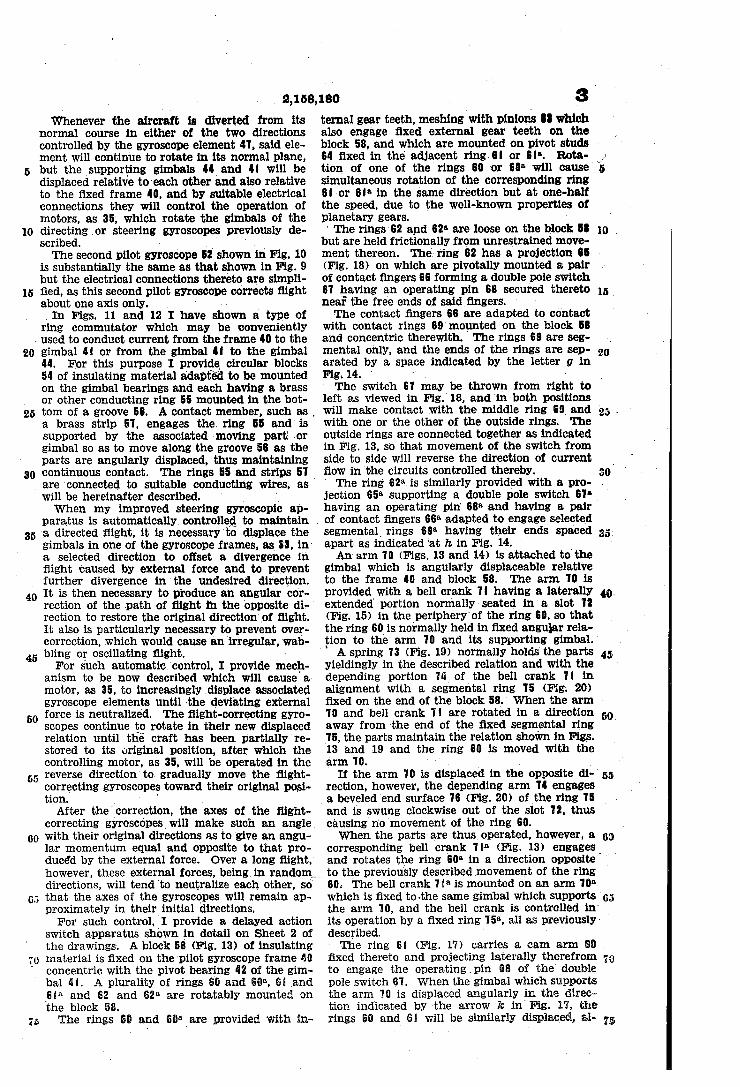
2,158,130 Whenever the aircraft is diverted from its
normal course in either of the two directions controlled by the gyroscope element l1, said ele ment will continue to rotate in its normal plane, but the _supporting gimbals 44 and 4I will be displaced relative to`each other and also relative to the fixed frame 40, and by suitable electrical connections they will control the operation of motors, as 35, which rotate the gimbals of the directingïor steering gyroscopes previously de scribed. » ' ` ~
The second pilot gyroscope 52 shown in Fig. 10 is substantially the same as that shown in Fig. 9 but the electrical connections thereto are simpli ñed, as this second pilot gyroscope corrects iiight about one axis only. ' ’ `
_In Figs. 11 and 12 I have shown a type of ring commutator which may be conveniently
. used to conduct current from the frame 40 to the gimbal 4I or from the gimbal Il to the gimbal 44. For this purpose I provide circular blocks 54 of insulating material adapted to be mounted on the gimbal bearings and each having a brass or other conducting ring 55 mounted in the bot tom of a groove 5B. A contact member, such as , a brass strip 51, engages the. ring 55 and is supported 'by the associated moving part' `or gimbal so as to move along the groove 55 as the parts are angularly displaced, thus maintaining continuous contact. The rings 55 and strips 51 are >connected to suitable conducting wires, as will be hereinafter described. ' ' ‘
When my improved steering gyroscopic ap paratus is automatically controlle to maintain _a directed night, it is necessary to displace the gimbals in one of the gyroscope frames, as 33, in a selected direction to oifset a divergence in ilight caused by external force and to prevent further divergence inthe undesired direction. It is then necessary to produce an angular cor rection of the .path of flight in the opposite di rection to restore the original direction‘of flight. It also is particularly necessary to prevent over correction, which would cause an irregular, wab bling or oscillating night. For such automatic control, I provide mech
anism to be now described which will cause'a motor, as 35, to increasingly displace associated gyroscope elements until -the deviating external force is neutralized. The night-correcting gyro scopes continue to rotate in their new displaced relation until the craft has been partially re stored to its original position, after which the controlling motor, as 35, will be operated in the
. reverse direction'to gradually move the flight correcting gyroscopes toward their original posi tion. , ' .
After theÍcorrection, the axes of the flight correcting gyroscopes will make such an angle _' with their original directions as to give an angu lar momentum equal and opposite to that pro duced by the external force. Over a long night, however, these external forces, beingvin randomv directions, will tend 'to neutralize each other, so"
_ that the axes of the gyroscopes will remain ap proximately in their initial directions. For such control, ̀ I provide a delayed action
switch apparatus shown in detail on Sheet 2 oi the drawings. A block 58 (Fig. 13) of insulating material is fixed on the-pilot gyroscope frame Mi concentric with the pivot bearing 42 of the gim bal 4I. A plurality of rings Bil and 5132, 5i and ,Sie and 62 and 52“ are rotatably mounted on the block 53. The rings E@ and Silß‘are provided with in
3 ternal gear teeth, meshing 'with pinions Il which also engage ñxed external gear teeth on the block 58, and which are mounted on pivot studs t4 fixed in the' adjacent ring‘sl or sie. Rnta- ' tion of one of the rings 60 >or 6i)a will ,cause> simultaneous rotation of the corresponding ring 5I or 6Ia in the same direction but at one-half the speed, due to the well-known properties of planetary gears.
‘ The rings 62 and |52'L are loose on the block 58 but are held frictionally from unrestrained move ment thereon. 'I'he-ring 62 has a projection B5 -v (Fig. 18) on which are pivotally mounted a pair of contact fingers 66 forming a double _pole switch 61 having an operating pin 68 secured thereto near the free ends o_f said ñngers. The contact fingers 66 are adapted to contact
with contact rings 69 mounted on the block 58 and concentric therewith. 'I'he rings 69 are seg mental only, and the ends of the rings are sep arated by a space indicated by the letter g in Fig. 14. '
The switch 61 may be thrown from right to left as viewed in Fig.~ 18, and in both positions will make contact with the middle ring 63 and with one or the other of the outside rings. 'I'he outside rings are connected together as indicated in Fig. 13, so that movement of the switch from side to side will reverse the direction of current flow in the circuits controlled thereby. ' The ring 62a. is similarly provided with a pro jection 65“ supporting a double pole switch 61* having an operating pin' 88a and having a pair '
10.
15.
20
so
of contact iingers 66a adapted to engage selected . segmental rings (59a having their ends spaced apart as yindicated îat h in Fig. 14. ` An arm 10 (Figs. 13 and 14) is attached to the
gimbal which is angularly displaceable relative to the frame 40 and block 58. The arm 10 is provided with a bell crank 1| having a laterally extended portion normally seated in a slot 12 (Fig. 15) in the‘periphery‘of the ring 60, so that the ring 60Fis normally held in fixed angular rela tion to thev arm 10 and its supporting gimbal. A spring 13 (Fig. 19) normally holds the parts
yieldingly in the described relation and with the depending portion 1li of the bell crank 1I in alignment with a segmental ring 15 (Fig. 20) fixed on the end of the block 58. When the arm 10 and bell crank 1l are rotated in a direction away from the end of the ilxed segmental ring `15, the parts maintain the relation shown in Figs. 13 and -19 and the ring 60 is moved with the »arm 10. « ‘ ‘ _
If the arm 10 is displaced in the opposite di rection, however, the depending arm 14 engages a beveled end surface 16 (Fig. 20) of the ring 15 and is swung clockwise out of the slot 12,. thus causing n'o movement of the ring 60. When the parts are thus operated, however, a
as.
45
55
corresponding bell crank 1Iß (Fig. 13) engages` y and rotates the ring 60B in a direction opposite to the previously described movement of the ring 60.~ The bell crank 1 ia is mounted on an arm 10°» which is fixed to-the same gimbal which supports ' the arm 10, and the bell crank is controlled in‘ its operation by a fixed ring 15a, all as previously> described. The ring El iFig; 17) carries a cam arm 8B
fixed thereto and projecting laterally therefrom to engage the operatingpin 68 of the double pole switch 61. When the gimbal which supports the arm 1i) is displaced angularly in the direc tion indicated'by ~the arrow k in'Fig. 17, the rings 6G and @i will be similarly displaced, al as»
5
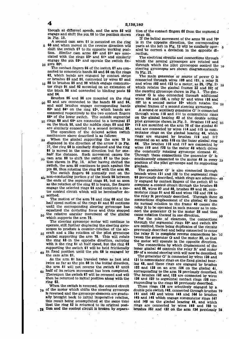
4 though at different speeds, and the arm 80 will engage and shift the pin 68 to the position shown in Fig. 18. , ‘
A second cam arm 8| is mounted on the ring 60 and when moved in the reverse direction will shift the. switch 61 to its opposite working posi tion.v Similar cam arms 80ß and 8|“ are asso ciated with the rings 6|lll and 6|“ and similarly engage the pin 68e and'operate the switch iin
10 gers 668.- . >
15
The contact fingers 66 of the switch 61 are con ' nected to concentric bands 83 and 84 on the rings 62, which bands are engaged by contact strips or brushes 85 and 86, connected by wires 81 and 88 to brushes 89 and 90 which engage commuta tor rings 9| and 92 mounted on an extension of the block 58 and connected to binding posts 93 and 94. , ' .
Brushes 95 and 96 are mounted on the ring 20 62 and are connected to the bands l83 and 84,
25
,40,
45
55
and said brushes engage corresponding bands 83il and -84a on the ring 62B, winch bands are connected respectively to the two contact lingers 66° of the lower switch. The outside segmental ' rings 69 and 69a are connected to a terminal 91 on the block 58, and the middle rings 69 and 69IL are similarly connected to a second terminal 98. The operation of the delayed action switch
mechanism above described is as follows: When the gimbal supporting the arm 10.is
displaced in the direction of the arrow k in Fig. 17, the ring 60 is similarly displaced and the ring 6| is moved in the same direction but for one half the distance. Such movement causes the cam arm 80 to shift the switch 61 to the posi tion‘shown in Fig._18.’ After having shifted the ' switch, the arm 80 continues to push against the pin 68, thus rotating the ring 62 with the arm 80. The switch fingers 66 normally rest on the
, non-conducting portion g of the ,block 58 between ` the ends of the segmental rings 69, but as soon as the rotation of the ring 62 is begun, the .iingers engage the selected rings 69 and complete a mo tor control circuit which will be hereinafter de scribed. ' f
The motion of the arm 10 and ring 60 and the half speed motion of the rings 6| and 62 continue until the corresponding steering gyroscope has equalized the deviating force and thus stopped Athe relative angular movement of the> gimbal which supports the arm 10. The steering gyroscope motor will continueìto
operate, still further displacing the steering gyro scopes to produce a counter-rotation of the _air craft and a like rotation of the pilotgyroscope gimbal supporting the arm 10. 'I‘his will rotate
« the ring 60\in the opposite direction, carrying
60
with it the ring 6|‘at half speed, but the ring 62 supporting the switch 61 will be held frictionally in fixed position until the pin 68 is engaged by the cam arm 8|. ‘ '
As the arm 8| has traveled twice as fast and twice as far as the pin 68 in the initial direction,
_ the arm 8| will not reverse the switch 61 until
65
70
half of its return movement has been completed. Thereupon the switch 61 >will be reversed and will
` then be returned to initial position along with the ,_ Vring' 62. '
When the switch is reversed, the control circuit of the motor which shifts the steering gyroscope is reversed‘and the gyroscope elements are gradu ally brought back to initial inoperative relation, this result being accomplished> at the same time that the ring 62 is returned to its _original posi
\ „r tion and the control circuit is broken by separa
2,158,180 tion of the contact ~lingers 66 from the segment; »l rings 69. `
If the initial movement of the arms 10- and 10'L is in the opposite direction, the corresponding Y parts at the left in Fig. 13 will be similarly oper ated “to correct a deviation in the opposite'di
l rection.
'I‘he electrical circuits and connections through which `the several gyroscopes are rotated and through which the pilot gyroscopes control the steering gyroscopes are shown diagrammatically in Fig. -21. .
The main generator or source of power G is connected through wires |00 and |0|,a relay R and wires |02 and |03 to a motor, as 35, (Fig. 3) which rotates the gimbal frames 32 and 32g* of the steering gyroscope shown in Fig. 1. 'I'he gen erator G is also ‘connected through additional wires |04 and |05, a relay R' and wires |06 and |01 to a 'second motor 35a which rotates the gimbal> frames of a second steering gyroscope. A second or auxiliary generator G' is connected
through wires ||0 and ||| to commutator rings on the gimbal bearing 42 of the double acting pilot gyroscope shown in Fig. 9. Brushes | |2 and ||3 are mounted on the arm 10 of the gimbal 4|
, and are connected by wires || 4 and ||5 to com'- 4 mutator rings on the gimbal bearing 46, which. rings are engaged by brushes ||6 >and ||1 mounted on an arm ||8 on the> inner gimbal ring 44. 'I'he brushes ||6 and [||1 are connected by wires ||9 and |20 to the motor 48 which drives the constantly rotating gyroscope element 41. Through these connections the generator G’ is continuously connected to the motor 48 in every position of the pllot‘gyroscope and its supporting gimbals. _ c ’ >
The generator G' is also connected through _ branch wires |2| and I|22 to the segmental rings 69 previously described, which rings are selective ly engaged by contact fingers of the switch 61 to complete a control circ'uit through the brushes 85 and 86, wires 81 and 88, brushes 89 and 90, com mutator rings 9| and 92 and wires |23 and |24 to the relay R. previously described. Through these connections displacement of the gimbal 4| from its normal relation to the frame 40 causes the relay R to be operated in such manner as to con nect the generator G tothe motor 3_5 and thus cause'rotation thereof in one direction. For the sake _of clearness, the connections
through thé segmental rings 69“ and switch 61n are omitted, these being duplicates of the circuits previouslyndescribcd and being connected to cause the relay R to complete reverse connections be- ' tween the generator G and the motor4 35, so that the motor will operate in'the opposite direction. The connections by which displacement of the
inner gimbal 44 controls the relay R' and motor 35Il of a second steering unit will now be described. The generator G' is connected by wires |30 and
| 3| to commutator rings on the ñxed gimbal bear ing 43,.and these rings are engaged by brushes |32 and |33 on an arm |34 on the gimbal 4|, corresponding to the arm 10 previously described. "I'he »brushes |32 and |33 are connected by wires |36 and |31 to segmental contact rings |38 cor responding to the rings 69 previously described. These rings |38 are selectively engaged by a
double pole switch |40, connected through brushes |4| and |42 and wires |43 and |44 to brushes |45 and |46 which engage commutator rings |41 ,and |48 on the gimbal bearing 45, and which rings are connected Ãby wires ~|49 and |50 to brushes |6| and |52 on the arm |34l previously`
15
25
35
45
50
60
70
75
10
15
20
25
'arcaico described. These brushes are connected through collector rings on the gimbal bearing 43 to wires |53 and |54 which lead to the relay R'. When the inner gimbal 44 is displaced.A from its
normal position in either direction, connection will be completed through the switch |40 to se lected segmental rings |38 so that the relay R' will be energized to connect the generator G to rotate the motor .35* in the indicated direction. It will be understood that a second switch cor responding to the switch |40 and a second set of segmental rings corresponding to therings |38 will be provided to indicate displacement of the gimbal 44 in the opposite direction. With the connections described, it'will be evi
dent that the motors 35 and 35“ which respec tively control two diil'erent steering gyroscopes'2 will be operated in accordance with the displace ment of the gimbals 4| and 44 respectively with reference to the rotating gyroscope element 4-1.
'I'he connections from the single acting pilot gyroscope shown inFig. 10 are substantially the same as the connections through which the motor 35 in Fig. 21 is controlled; As this second pilot Ygyroscope controls only a sixl'gle steering gyro scope, the connections described for control of a second motor, as 358, need not be provided.
30
45
60
70
Through the apparatus and connections which have now been described in detail, an aircraft may be maintained in flight in a predetermined direction, In the event of deviation in any direc tion due to external forces, the steering and oon trol _apparatus described will immediately restore the craft to its original direction of ñight.
Alterationv of the course may be effected by manual displacement of the rotating gyroscope element in one of the pilot units. If the element is caused to rotate in a new and different plane, the steering gyroscopes will immediately operate Ato align the craft on its new course as deter mined by the pilot gyroscopes. » While the pilot gyroscopes may be of relatively
small size to economize weight and cost, the main or steering gyroscopes, such as are shown` in Fig. 1, 'must be of large dimensions »and the rotating elements must be of substantial mass and rotate at relatively high speed in order 'to supply enough angular momentum to apply an eñective turning force to the craft. It is also essential in light aircraft, such as rockets or rocket planes, that the weight be reduced where ever possible.` .
A further feature of my invention relates to the provision of'hollow rotating gyroscope elements for the steering gyroscopes, which hollow ele ments may be filled with liquid fuel such as is used in propelling the craft. ’I‘his liquid fuel confined within the hollow gyroscopes provides the necessary mass for effective flight control. As the flight continues and the regular fuel sup ply decreases, the fuel in the gyroscopes may be gradually withdrawn for combustion purposes. Although the gradual loss of liquid from the
gyroscopes will of course lighten the gyroscopes and hence tend to reduce their corrective action, this will not be a serious disadvantage, since a large part of the weight ofthe craft is in the fuel load, and by the time the fuel tanks are nearly empty the Weight of the craft will have been re duced suñiciently so that even the empty gyro scopes will‘produce eEective ñight correction.
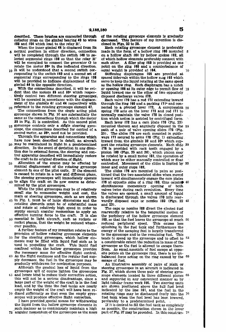
I have providedspecial means for withdrawing the liquid from the hollow gyroscope elements in
__such manner as to continuously maintain a high 75 angular momentum -of the gyroscopes as the mass
I' escape of fuel. »
n
5 of the >rotating gyroscope elements is gradually decreased. This feature of my invention is dis closed in Figs. 22 to _28.` , Each rotating gyroscope element is preferably
madein the form of a hollow ring |60 mounted on a hollow shaft |6| by hollow spokes |62, all of which hollow elements preferably connect with each other. A filler plug |63 is provided at one ' point on vthe ring |60 and a counterbalance of , -equal weight is provided at |64.
Stiffening diaphragms |65 are provided at spaced intervals withinr the hollow ring |60 which serve to keep the liquid rotating at the same speed as the hollow ring. Each diaphragm has a notch or opening |66 at its outer edge to permit flow of liquid toward one or the other of two oppositely disposed discharge valves I 10. Each valve |10 has a rod |1| extending inward
.through the ring |60 and a packing |1|a and con nected to a »pivoted lever |12. A compression spring |13 acts on the lever |12 and rod |1|_to normally maintain the valve |10 in closed posi tion which action is assisted by centrifugal force. Each lever |12 has a cam plate |15 (Fig. 23)
mounted thereon and angularly disposed in the path of a pair of valve opening slides |16 (Fig. 25). The slides | 16 are each mounted in guide ways |11 securedto arms |18 (Fig. 1) extending inward from the gimbals 32 and 32a which sup port the rotating gyroscope elements. Each slide |16 is provided with rack teeth engaged by a pinion |80 (Figs. 25 and .26), which pinion may be rotated‘by a small motor |8|,_the operation of which may be either manually controlled or float controlled. Movement of the slides is limited by inner and outer stops |82. y '
'I'he slides |16 are mounted in pairs soposi tioned that the two associated'slides when moved inward will simultaneously engage the cam plates |15 at opposite sides of a ring |60, thus causin? simultaneous momentary> _ opening of both valves twice during each revolution. Every time the valves are opened, a small amount of liquid is .discharged through the valves |10 into rear wardly disposed caps or nozzles |83 (Figs. 22 and 23). . '
‘I‘he caps or nozzles |83 direct the ejected'fuel rearwardly relative, to the tangential motion of the periphery of the hollow gyroscope element |60, so that the fuel leaves the gyroscope at much reduced peripheral speed. This causes less
f 'splashing in the fuel tank and furthermore the
10
15
20
25
35
40
45
50
energy of the escaping fuel is largely transferred ' to the gyroscope and to the remaining fuel. This tends to speed up the gyroscope and to offset to a considerable extent the reduction in mass ofthe `gyroscope as the fuel is allowed’to escape there from. As equal. amounts of'fuel escape at oppo site points on the gyroscope ring, there is no un balanced force acting on the ring caused by the
An illustrative assembly of pairs steering gyroscopes in'an aircraft is indicatedin Fig. 27, which shows three pair of steering gyro scope elements located in three different planes and supported in any convenient manner as by light tubular frame work |90. Two steering units are shown positioned above the full fuel level .indicated rby the line lill, and the fuel in the rotating rings may -be discharged freely into the fuel tank when the fuel level has been lowered, preferably to a predetermined point.
of m`ain or`
55
60
65
70
If it is desired to illl the fuel tank as completelyv i as possible, the construction shown in the lower part of Fig. 27 may be provided. In this construc
20
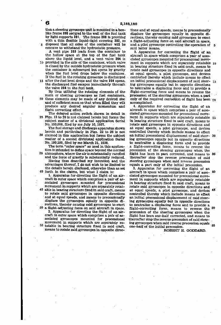
25
6 tion a steering gyroscope unit is mounted in a box like frame 200 secured to the wall of the fuel tank by light supports 20|. 'I'he frame 200 is provided with a thin nexible liquid-tight covering 202, so disposed'that all sides of the container will be concave to withstand the hydrostatic pressure. A vent pipe 203 leads from the container to
the hollow space at the top of the fuel .tank above the liquid level, and a vent valve 204I is provided in the side of the container, which valve is closed by the outside hydrostatic pressure. when the container is submerged but lopens by gravity when the fuel level drops below the container. If the fuel in the rotating gyroscope is discharged after the fuel level drops and the valve 204 opens, the discharged fuel escapes immediately through the valve 204 to the fuel tank. ' By thus utilizing the rotating elements of the
main or steering gyroscopes as fuel containers, these elements may be made of any desired size and of sufiicient mass so that when nlled they will produce any desired angular momentum and night correcting effect. l The delayed action switch shown in detail in
Figs. 13 to 20 is not claimed herein but forms the subject matter of a divisional application Serial ‘
- N0. 153,009, filed by me July 10, 1937.
30
35
40
45
55
The fuel storage and discharge apparatus shown herein and particularly in Figs. 22 to 28 is not claimed in this application but forms the subject matter of a second divisional application Serial . No. 199,180, filed by me-March 3l, 1938. The term “outer space” as used in this applica
tion is intended to denne space beyond the normal atmosphere, where the air is substantially rarened and the force of gravity is substantially reduced. Having thus described my invention and the
advantages thereof, I do not wish to be limited to the details herein disclosed, otherwise than as set forth in the claims, but what I claim is:
l. Apparatus forvdirecting the night of an air- ~ craft in outer space which comprises apair of as sociated `gyroscopes . mounted .for precessional movement in supports which are separately rotat-> able in bearing structure nxed in said craft, means to rotate said gyroscopes in opposite directions
' and at equal speeds, and means to precessionally displace 'the gyroscopes equally in oppositev di rections, therebycausing said gyroscopes to exert a night-adjusting force on said aircraft in space.
2. Apparatus for directing the night of an air craft _in outer space which comprises a pair of as sociated gyroscopes mounted for precessional movement in supports which are separately ro tatable in bearing structure nxed in said craft, means to rotate said gyroscopes in opposite direc
î .
1
tions and at equal speeds, means to precessionally displace the gyroscopes equally in opposite di rections, thereby causing said gyroscopes to exert a night-'adjusting force on said aircraft in space, and a pilot gyroscope controlling the operation of said latter means. 1
3. Apparatus for correcting the night of an aircraft in space which comprises a pair of asso ciated gyroscopes mounted for precessional move ment in supports which are separately rotatable in bearing structure nxed in said craft, means to rotate said gyroscopes in opposite directions and at equal speeds, a pilot gyroscope, and devices
- controlled thereby which include means to effect an initial precessional displacement of said steer ing gyroscopes equally but in opposite directions to neutralize a displacing force and to provide a night-correcting force and means to reverse the , precession of the steering gyroscopes when a part only of the required correction of night has been> accomplished. -
4. Apparatus for correcting the flight of' an aircraft in space which comprises a pair of asso- . ciated gyroscopes mounted for precessional move ment in supports which -are separately rotatable in bearing _structure ñxed in said craft, means to ’ rotate said gyroscopes in opposite directions and at equal speeds, a pilot gyroscope, and devices controlled thereby which include means to effect -an initial precessional displacement of said steer ing gyroscopes equally but in opposite directions to neutralize a displacing force and to provide
a night-correcting force,_ means to reverse the precession of the steering gyroscopes when the night has been in part corrected, and means to
30
thereafter stop the reverse precession of said y steering gyroscopes when said reverse precession
' equals a part only ofthe initial precession. 5. Apparatus -for correcting the night of an
aircraft-in space which comprises a pair of asso ciated gyroscopes mounted for precessional move ment in supports which are separately rotatable in bearing structure fixed in said craft. means to rotate said gyroscopes in opposite directions and at equal speeds, a pilot gyroscope, and devices controlled thereby which include means tol effect an initial precessional displacement of said steer ing gyroscopes equally but in opposite directions to neutralize a. displacing force and to provide a night-correcting force, means to reverse the precession of the steering gyroscopes when the night has been one-half corrected, and means to
40
50
thereafter stop the reverse precession of said steer- . ing gyroscopes when said reverse precession equals one-half of the initial precession.
‘ ROBERT H. GODDARD.


![Gilbert, K. E. & Kuhn, H. - Istoria Esteticii [1939]](https://img.pdfslide.us/doc/110x75/5572029f4979599169a3d963/gilbert-k-e-kuhn-h-istoria-esteticii-1939.jpg)