Embed Size (px)
Citation preview
May the Force Be With You Revit Tips and Tricks
David Cohn
Do you want to become a Revit master? In this fun and informative class, you’ll learn a host of Revit tips and tricks that you can take home and use every day. Learn how to make your drawings look exactly the way you want, quickly create custom tags, share coordinates, adjust the appearance and structure of walls without having to create new wall types, create sloped walls and other sophisticated shapes, and more. Whether you’re new to Revit or a seasoned veteran, you’ll learn something new, guaranteed to make you even more productive.
About the Speaker: David has more than 25 years of hands-on experience with AutoCAD® as a user, developer, author, and consultant. He is an independent CAD consultant, a contributing editor to Desktop Engineering magazine, the former publisher and editor-in-chief of CADCAMNet and Engineering Automation Report, the former senior editor of CADalyst magazine, and the author of more than a dozen books about AutoCAD. A licensed architect, David was also one of the earliest AutoCAD third-party software developers, creating numerous AutoCAD add-on programs. As an industry consultant, David has worked with many companies including Autodesk. He teaches college-level AutoCAD courses and is always a popular presenter at both Autodesk University and AUGI® CAD Camps.
[email protected] www.dscohn.com
2
Introduction Sure you can click your way through menus and dialog boxes, but as any truly proficient user of any program will tell you, one of the keys to becoming a power user is to find ways of getting things done faster, with the fewest number of clicks and picks. The following collection of tips is designed to help you achieve that goal—in Revit.
These tips are presented in no particular order, and are based on Revit Architecture 2010.
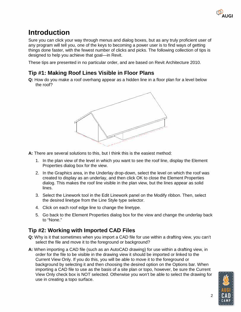
Tip #1: Making Roof Lines Visible in Floor Plans Q: How do you make a roof overhang appear as a hidden line in a floor plan for a level below
the roof?
A: There are several solutions to this, but I think this is the easiest method:
1. In the plan view of the level in which you want to see the roof line, display the Element Properties dialog box for the view.
2. In the Graphics area, in the Underlay drop-down, select the level on which the roof was created to display as an underlay, and then click OK to close the Element Properties dialog. This makes the roof line visible in the plan view, but the lines appear as solid lines.
3. Select the Linework tool in the Edit Linework panel on the Modify ribbon. Then, select the desired linetype from the Line Style type selector.
4. Click on each roof edge line to change the linetype.
5. Go back to the Element Properties dialog box for the view and change the underlay back to “None.”
Tip #2: Working with Imported CAD Files Q: Why is it that sometimes when you import a CAD file for use within a drafting view, you can’t
select the file and move it to the foreground or background?
A: When importing a CAD file (such as an AutoCAD drawing) for use within a drafting view, in order for the file to be visible in the drawing view it should be imported or linked to the Current View Only. If you do this, you will be able to move it to the foreground or background by selecting it and then choosing the desired option on the Options bar. When importing a CAD file to use as the basis of a site plan or topo, however, be sure the Current View Only check box is NOT selected. Otherwise you won’t be able to select the drawing for use in creating a topo surface.
3
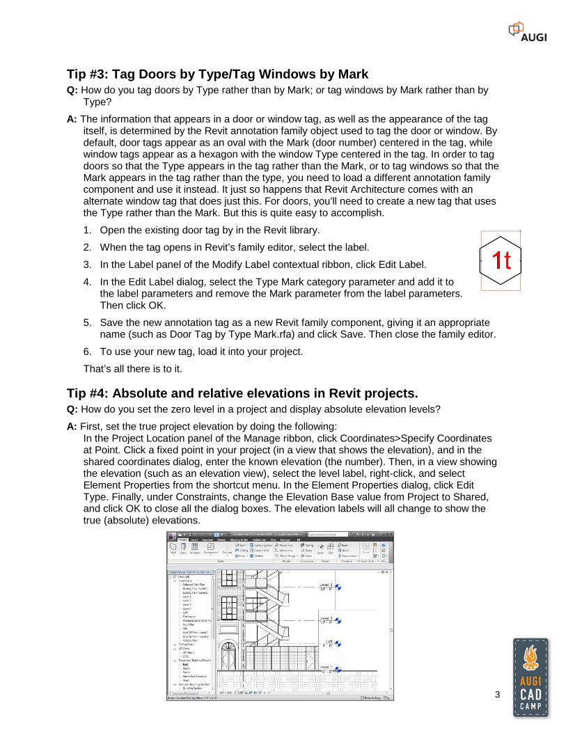
Tip #3: Tag Doors by Type/Tag Windows by Mark Q: How do you tag doors by Type rather than by Mark; or tag windows by Mark rather than by
Type?
A: The information that appears in a door or window tag, as well as the appearance of the tag itself, is determined by the Revit annotation family object used to tag the door or window. By default, door tags appear as an oval with the Mark (door number) centered in the tag, while window tags appear as a hexagon with the window Type centered in the tag. In order to tag doors so that the Type appears in the tag rather than the Mark, or to tag windows so that the Mark appears in the tag rather than the type, you need to load a different annotation family component and use it instead. It just so happens that Revit Architecture comes with an alternate window tag that does just this. For doors, you’ll need to create a new tag that uses the Type rather than the Mark. But this is quite easy to accomplish.
1. Open the existing door tag by in the Revit library.
2. When the tag opens in Revit’s family editor, select the label.
3. In the Label panel of the Modify Label contextual ribbon, click Edit Label.
4. In the Edit Label dialog, select the Type Mark category parameter and add it to the label parameters and remove the Mark parameter from the label parameters. Then click OK.
5. Save the new annotation tag as a new Revit family component, giving it an appropriate name (such as Door Tag by Type Mark.rfa) and click Save. Then close the family editor.
6. To use your new tag, load it into your project.
That’s all there is to it.
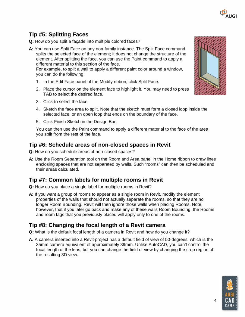
Tip #4: Absolute and relative elevations in Revit projects. Q: How do you set the zero level in a project and display absolute elevation levels?
A: First, set the true project elevation by doing the following: In the Project Location panel of the Manage ribbon, click Coordinates>Specify Coordinates at Point. Click a fixed point in your project (in a view that shows the elevation), and in the shared coordinates dialog, enter the known elevation (the number). Then, in a view showing the elevation (such as an elevation view), select the level label, right-click, and select Element Properties from the shortcut menu. In the Element Properties dialog, click Edit Type. Finally, under Constraints, change the Elevation Base value from Project to Shared, and click OK to close all the dialog boxes. The elevation labels will all change to show the true (absolute) elevations.
4
Tip #5: Splitting Faces Q: How do you split a façade into multiple colored faces?
A: You can use Split Face on any non-family instance. The Split Face command splits the selected face of the element; it does not change the structure of the element. After splitting the face, you can use the Paint command to apply a different material to this section of the face. For example, to split a wall to apply a different paint color around a window, you can do the following:
1. In the Edit Face panel of the Modify ribbon, click Split Face.
2. Place the cursor on the element face to highlight it. You may need to press TAB to select the desired face.
3. Click to select the face.
4. Sketch the face area to split. Note that the sketch must form a closed loop inside the selected face, or an open loop that ends on the boundary of the face.
5. Click Finish Sketch in the Design Bar.
You can then use the Paint command to apply a different material to the face of the area you split from the rest of the face.
Tip #6: Schedule areas of non-closed spaces in Revit Q: How do you schedule areas of non-closed spaces?
A: Use the Room Separation tool on the Room and Area panel in the Home ribbon to draw lines enclosing spaces that are not separated by walls. Such “rooms” can then be scheduled and their areas calculated.
Tip #7: Common labels for multiple rooms in Revit Q: How do you place a single label for multiple rooms in Revit?
A: If you want a group of rooms to appear as a single room in Revit, modify the element properties of the walls that should not actually separate the rooms, so that they are no longer Room Bounding. Revit will then ignore those walls when placing Rooms. Note, however, that if you later go back and make any of these walls Room Bounding, the Rooms and room tags that you previously placed will apply only to one of the rooms.
Tip #8: Changing the focal length of a Revit camera Q: What is the default focal length of a camera in Revit and how do you change it?
A: A camera inserted into a Revit project has a default field of view of 50-degrees, which is the 35mm camera equivalent of approximately 39mm. Unlike AutoCAD, you can’t control the focal length of the lens, but you can change the field of view by changing the crop region of the resulting 3D view.
5
Tip #9: Changing the eye level height in a Revit walkthrough Q: How do you change the eye level height in a Revit 3D walkthrough?
A: When you initially create the walkthrough, Revit assigns one global eye level height for all of the keyframes. After initially creating the walkthrough path, however, select the walkthrough, switch to an Elevation view, and on the Options bar, click Edit Walkthrough. Then, on the Options bar, from the Controls drop-down, select Path. You can then move the individual key points of the walkthrough, including changing their elevation.
Tip #10: Creating sloped walls in Revit Q: How do you create a sloped wall in Revit?
A: There are several ways to create a wall that diverts from the vertical axis. For example, you could create a curtain wall, create the wall as an in-place family, use the Wall by Face function, or use wall sweeps and reveals in the wall definition. Here’s a quick method, creating a sloped wall as an in-place family using a solid sweep:
1. On the Modeling panel of the Design bar, click Create and then choose Walls from the Family Category and Parameters dialog box. Assign a name to the new wall you are creating.
2. In the Family panel of the Design bar, click Solid Form > Solid Sweep.
3. On the Sketch panel, click Sketch 2D Path and then sketch the path of the wall in plan view. When finished, click Finish Path.
4. On the Sketch panel, click Sketch Profile. In the Go to View dialog box, select the view in which you will define the profile, and then click Open View.
5. Use the Sketch tools to define the profile of the sloping wall. Be sure the sketch forms a closed loop. When finished, click Finish Profile.
6. On the Sketch panel, click Finish Sweep. Then click Finish Family.
The wall now behaves like any other wall, including the ability to host doors and windows, although windows and doors inserted into sloped portions of walls may not align with the wall and may therefore need to be modified.
Tip #11: Revit’s built-in calculator Q: Is there a way to perform calculations while entering distances and angles in Revit?
A: Yes. Revit actually has a built-in calculator that you can use at any time while entering distances or parameters. To use this “hidden” feature in Revit, simply preface the distance or parameter you are entering with an equal sign (=), and then enter the formula. You can use any standard arithmetic formula. For example, to create a wall half of 32’-6 7/8”, enter the distance as =32’6 7/8 / 2.
6
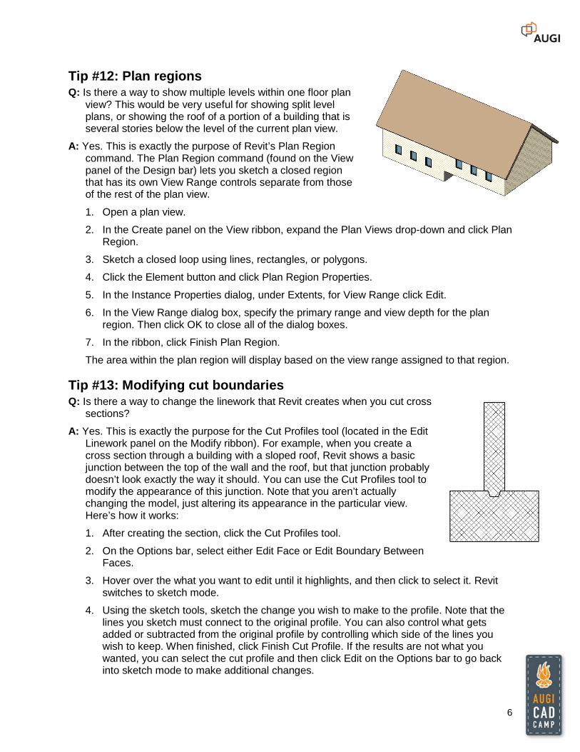
Tip #12: Plan regions Q: Is there a way to show multiple levels within one floor plan
view? This would be very useful for showing split level plans, or showing the roof of a portion of a building that is several stories below the level of the current plan view.
A: Yes. This is exactly the purpose of Revit’s Plan Region command. The Plan Region command (found on the View panel of the Design bar) lets you sketch a closed region that has its own View Range controls separate from those of the rest of the plan view.
1. Open a plan view.
2. In the Create panel on the View ribbon, expand the Plan Views drop-down and click Plan Region.
3. Sketch a closed loop using lines, rectangles, or polygons.
4. Click the Element button and click Plan Region Properties.
5. In the Instance Properties dialog, under Extents, for View Range click Edit.
6. In the View Range dialog box, specify the primary range and view depth for the plan region. Then click OK to close all of the dialog boxes.
7. In the ribbon, click Finish Plan Region.
The area within the plan region will display based on the view range assigned to that region.
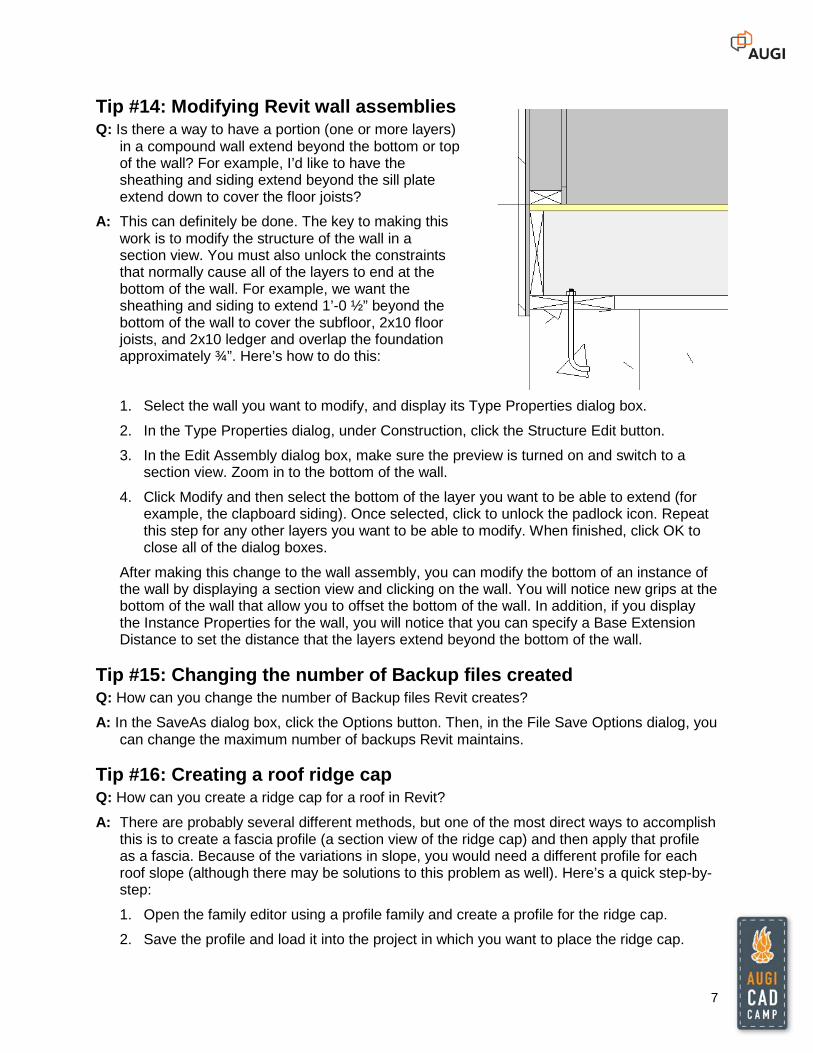
Tip #13: Modifying cut boundaries Q: Is there a way to change the linework that Revit creates when you cut cross
sections?
A: Yes. This is exactly the purpose for the Cut Profiles tool (located in the Edit Linework panel on the Modify ribbon). For example, when you create a cross section through a building with a sloped roof, Revit shows a basic junction between the top of the wall and the roof, but that junction probably doesn’t look exactly the way it should. You can use the Cut Profiles tool to modify the appearance of this junction. Note that you aren’t actually changing the model, just altering its appearance in the particular view. Here’s how it works:
1. After creating the section, click the Cut Profiles tool.
2. On the Options bar, select either Edit Face or Edit Boundary Between Faces.
3. Hover over the what you want to edit until it highlights, and then click to select it. Revit switches to sketch mode.
4. Using the sketch tools, sketch the change you wish to make to the profile. Note that the lines you sketch must connect to the original profile. You can also control what gets added or subtracted from the original profile by controlling which side of the lines you wish to keep. When finished, click Finish Cut Profile. If the results are not what you wanted, you can select the cut profile and then click Edit on the Options bar to go back into sketch mode to make additional changes.
7
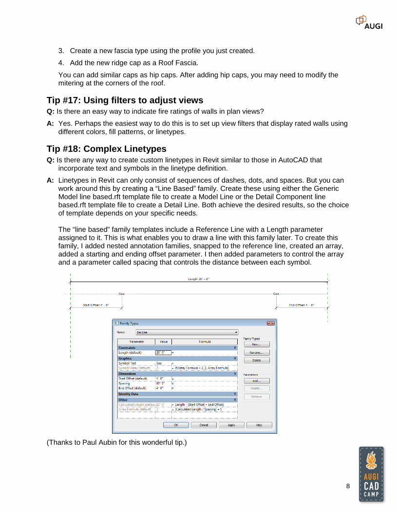
Tip #14: Modifying Revit wall assemblies Q: Is there a way to have a portion (one or more layers)
in a compound wall extend beyond the bottom or top of the wall? For example, I’d like to have the sheathing and siding extend beyond the sill plate extend down to cover the floor joists?
A: This can definitely be done. The key to making this work is to modify the structure of the wall in a section view. You must also unlock the constraints that normally cause all of the layers to end at the bottom of the wall. For example, we want the sheathing and siding to extend 1’-0 ½” beyond the bottom of the wall to cover the subfloor, 2x10 floor joists, and 2x10 ledger and overlap the foundation approximately ¾”. Here’s how to do this:
1. Select the wall you want to modify, and display its Type Properties dialog box.
2. In the Type Properties dialog, under Construction, click the Structure Edit button.
3. In the Edit Assembly dialog box, make sure the preview is turned on and switch to a section view. Zoom in to the bottom of the wall.
4. Click Modify and then select the bottom of the layer you want to be able to extend (for example, the clapboard siding). Once selected, click to unlock the padlock icon. Repeat this step for any other layers you want to be able to modify. When finished, click OK to close all of the dialog boxes.
After making this change to the wall assembly, you can modify the bottom of an instance of the wall by displaying a section view and clicking on the wall. You will notice new grips at the bottom of the wall that allow you to offset the bottom of the wall. In addition, if you display the Instance Properties for the wall, you will notice that you can specify a Base Extension Distance to set the distance that the layers extend beyond the bottom of the wall.
Tip #15: Changing the number of Backup files created Q: How can you change the number of Backup files Revit creates?
A: In the SaveAs dialog box, click the Options button. Then, in the File Save Options dialog, you can change the maximum number of backups Revit maintains.
Tip #16: Creating a roof ridge cap Q: How can you create a ridge cap for a roof in Revit?
A: There are probably several different methods, but one of the most direct ways to accomplish this is to create a fascia profile (a section view of the ridge cap) and then apply that profile as a fascia. Because of the variations in slope, you would need a different profile for each roof slope (although there may be solutions to this problem as well). Here’s a quick step-by-step:
1. Open the family editor using a profile family and create a profile for the ridge cap.
2. Save the profile and load it into the project in which you want to place the ridge cap.
8
3. Create a new fascia type using the profile you just created.
4. Add the new ridge cap as a Roof Fascia.
You can add similar caps as hip caps. After adding hip caps, you may need to modify the mitering at the corners of the roof.
Tip #17: Using filters to adjust views Q: Is there an easy way to indicate fire ratings of walls in plan views?
A: Yes. Perhaps the easiest way to do this is to set up view filters that display rated walls using different colors, fill patterns, or linetypes.
Tip #18: Complex Linetypes Q: Is there any way to create custom linetypes in Revit similar to those in AutoCAD that
incorporate text and symbols in the linetype definition.
A: Linetypes in Revit can only consist of sequences of dashes, dots, and spaces. But you can work around this by creating a “Line Based” family. Create these using either the Generic Model line based.rft template file to create a Model Line or the Detail Component line based.rft template file to create a Detail Line. Both achieve the desired results, so the choice of template depends on your specific needs. The “line based” family templates include a Reference Line with a Length parameter assigned to it. This is what enables you to draw a line with this family later. To create this family, I added nested annotation families, snapped to the reference line, created an array, added a starting and ending offset parameter. I then added parameters to control the array and a parameter called spacing that controls the distance between each symbol.
(Thanks to Paul Aubin for this wonderful tip.)
9
Tip #19: Quickly hiding elements Q: Is there a way to quickly hide elements?
A: Yes. You can right-click on an element and then select Hide from the shortcut menu to permanently hide the element. You can also use this to hide entire categories or hide objects by applying a filter. To redisplay hidden objects, click Reveal Hidden Elements.
Tip #20: Quick Delete Q: Is there an easier way to delete objects other than selecting them and then pressing the
Delete key (or right-clicking)?
A: Yes. If you hold down the Delete key, Revit will then immediately delete each object you select while the Delete key is depressed.
Tip #21: Previous selection set Q: AutoCAD remembers the previous selection set. Is there anything similar in Revit?
A: Yes. The Ctrl+left-arrow keyboard combination reselects the previous objects, as long as you haven’t already selected anything new or clicked in a dialog box.
Tip #22: Using shortcut keys Q: I’m used to typing in AutoCAD. Can I type in Revit to get things done more quickly?
A: Absolutely. If you press the ALT key, Revit displays letters and numbers associated with different commands and areas of the ribbon. You can type those letters or numbers while pressing the ALT key to start that command. So ALT+M would switch to the Modify tab. Revit also has many keyboard shortcuts. You can see many of these shortcuts in various dialog boxes. For example, if you switch to the Manage ribbon and choose Settings>Snaps, the Snaps dialog shows the keyboard shortcuts for the various object snaps. If you open the file KeyboardShortcuts.txt, you can see all of the keyboard shortcuts and edit the file to create your own custom keyboard shortcuts. The comments in this file explain the syntax and how to modify the file. [Note that if you download the Revit Subscription Advantage Pack you can add a Customize button to the Options dialog so you can modify keyboard shortcuts using a dialog box.] I don’t recommend memorizing all of the available shortcuts, but some worth remembering include:: zoom to fit (ZF), visibility graphics (VG), view properties (VP), and render (RR).
Tip #23: Adjusting Project North, True North, and Plan Orientation Q: How can I make West be Up in my drawings? OR North is Up in my drawings but it’s not
“really” North. What’s the difference between Project North and True North? OR How do I get my project located to match my survey?
A: Each Revit project file has its own internal coordinate system which by default is only known to the project. If you project is a stand-alone, you may be able to live with this internal system. By default, North is toward the top of the project and truly faces north. When you first start a project, you should specify the project location using the nearest major city or latitude and longitude so that you can generate location-specific shadows if
10
necessary. Note that you can add new cities to the list by editing the file Sitename.txt. (If you don’t have actual survey data, Google the latitude and longitude for the city you want to add.) If you’ve started modeling your project before you locate the project, you probably started modeling with the long dimension of the building running left-to-right and no regard to where True North is located. That’s okay. You can rotate True North by switching to the Manage tab and in the Project Location panel, choosing Position>Rotate True North. This will change the angle for a project relative to True North. You can specify an angle on the Options bar or rotate graphically. If you want your view to be oriented with True North to the top, change the Orientation in the View Properties dialog (the Instance Properties dialog for the View). You can set this to either True North or Project North. If you want a North Arrow symbol added to the site plan pointing to true north, add it when the view is oriented to True North. When a plan view is oriented to Project North, you can also rotate the direction of Project North. To do this, in the Project Location panel of the Manage ribbon, choose Position>Rotate Project North. Note, however, that if you rotate project north after placing a north arrow, it will no longer be pointing in the proper direction. To fix this, switch the view orientation back to True North, fix the direction of the north arrow, and then switch the view orientation back to Project North. In terms of placing your project to match survey data, there are a number of ways to do this. If you receive a CAD file with accurate survey data, you can link the CAD file, move it under the project to match your project model, and then Acquire Coordinates from the CAD file. If you simply receive survey data for a datum point in your model, you can Specify Coordinates at a Point to accurately locate the building.
Tip #24: Using the ViewCube Q: Constantly switching between views takes a lot of time, and then I have a bunch of views
open. Is there an easier way? And how do you produce 3D sectional cutaway views?
A: The ViewCube is a tremendously useful tool in Revit. With the ViewCube, you can spend most of your time working in a 3D view as you model, instead of having to constantly switch between plan views and elevation views. For example, you can quickly jump to an elevation view by clicking on one of the faces of the ViewCube. You can also right-click on the ViewCube and reorient the 3D view to any existing view. You can also use the ViewCube to quickly create great 3D sectional cutaway views that cut your model exactly where you want. First, use the Section tool to create a cross section where you want to cut the model. Then, make a new 3D view and rename it. Finally, with that 3D view active, right-click on the ViewCube and reorient the view to your section view. The 3D view will match the section exactly. You can then spin the model to any angle you wish. To hide the crop box, you can select it, right-click, and choose Hide in View>Elements.
11
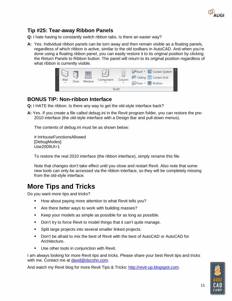
Tip #25: Tear-away Ribbon Panels Q: I hate having to constantly switch ribbon tabs. Is there an easier way?
A: Yes. Individual ribbon panels can be torn away and then remain visible as a floating panels, regardless of which ribbon is active, similar to the old toolbars in AutoCAD. And when you’re done using a floating ribbon panel, you can easily restore it to its original position by clicking the Return Panels to Ribbon button. The panel will return to its original position regardless of what ribbon is currently visible.
BONUS TIP: Non-ribbon Interface Q: I HATE the ribbon. Is there any way to get the old-style interface back?
A: Yes. If you create a file called debug.ini in the Revit program folder, you can restore the pre-2010 interface (the old-style interface with a Design Bar and pull-down menus). The contents of debug.ini must be as shown below: # InHouseFunctionsAllowed [DebugModes] Use2009UI=1 To restore the real 2010 interface (the ribbon interface), simply rename this file. Note that changes don’t take effect until you close and restart Revit. Also note that some new tools can only be accessed via the ribbon interface, so they will be completely missing from the old-style interface.
More Tips and Tricks Do you want more tips and tricks?
How about paying more attention to what Revit tells you?
Are there better ways to work with building masses?
Keep your models as simple as possible for as long as possible.
Don’t try to force Revit to model things that it can’t quite manage.
Split large projects into several smaller linked projects.
Don’t be afraid to mix the best of Revit with the best of AutoCAD or AutoCAD for Architecture.
Use other tools in conjunction with Revit.
I am always looking for more Revit tips and tricks. Please share your best Revit tips and tricks with me. Contact me at [email protected].
And watch my Revit blog for more Revit Tips & Tricks: http://revit-up.blogspot.com.