Embed Size (px)
Citation preview
May 9, 2005 Andrew C. Gallagher1 CRV2005
Using Vanishing Points toCorrect Camera Rotation
Andrew C. GallagherEastman Kodak Company
May 9, 2005 Andrew C. Gallagher2 CRV2005
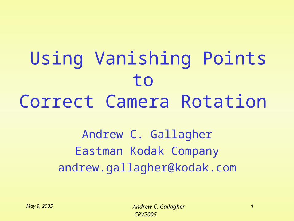
Problem• An unintentionally tilted camera can
negatively affect image appearance.• Caused by lightweight
cameras that are difficult to hold level.
• People prefer imageswhere the horizon is level.
• Human can see as little at 1o tilt.
May 9, 2005 Andrew C. Gallagher3 CRV2005
Solution• Vanishing point location can be used to detect
and correct image tilt resulting from camera rotation.
• A vanishing point is the image of a world line at infinity.
• Vanishing point location is useful for: – computing focal length [Kanatani]– finding principal point [Caprile et al.]– determining camera parameters and rotation
matrix[Cipolla et al.]
May 9, 2005 Andrew C. Gallagher4 CRV2005
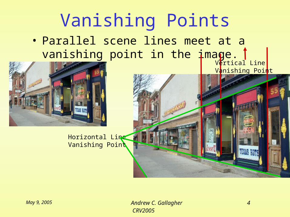
Vanishing Points• Parallel scene lines meet at a
vanishing point in the image.
Horizontal LineVanishing Point
Vertical LineVanishing Point
May 9, 2005 Andrew C. Gallagher5 CRV2005
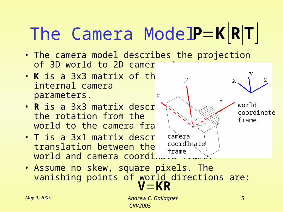
The Camera Model• The camera model describes the projection of
3D world to 2D camera plane. • K is a 3x3 matrix of the
internal camera parameters.
• R is a 3x3 matrix describing the rotation from the world to the camera frame.
• T is a 3x1 matrix describingtranslation between the world and camera coordinate frame.
• Assume no skew, square pixels. The vanishing points of world directions are:
TRKP
camera coordinate frame
worldcoordinate frame
KRV
May 9, 2005 Andrew C. Gallagher6 CRV2005
The Rotation Matrix• R is any matrix in the special orthogonal
group SO(3). • In practice the camera positions used by
typical consumers follow a fairly predictable nonlinear distribution.
• This distribution is then used to find where vanishing points will occur.
R
May 9, 2005 Andrew C. Gallagher7 CRV2005
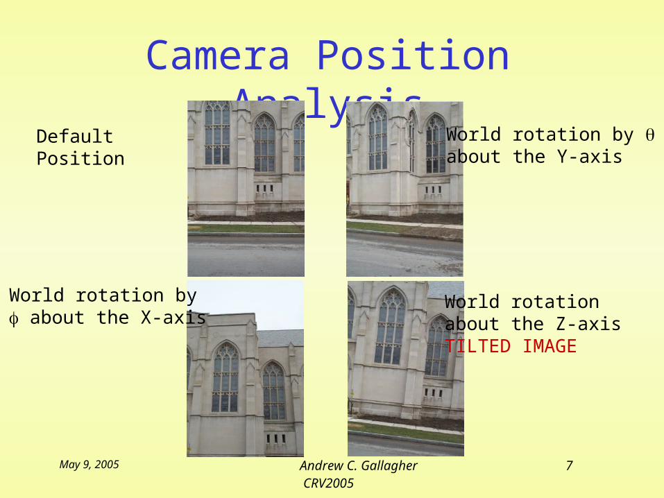
Camera Position Analysis Default
PositionWorld rotation by about the Y-axis
World rotation about the Z-axisTILTED IMAGE
World rotation by about the X-axis
May 9, 2005 Andrew C. Gallagher8 CRV2005
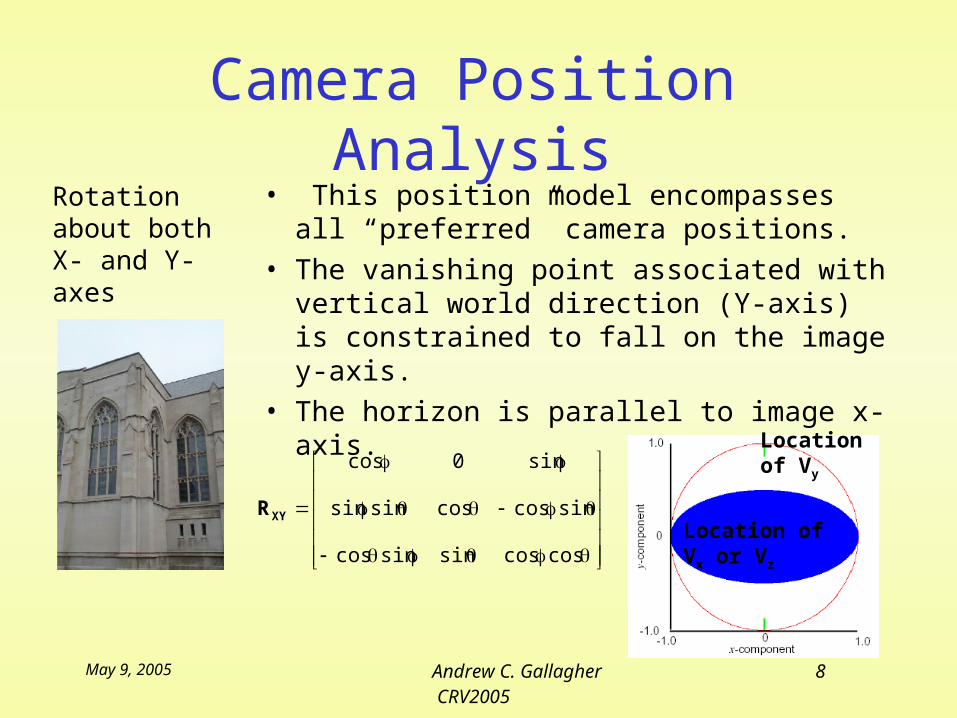
Camera Position Analysis Rotation
about both X- and Y- axes
• This position model encompasses all “preferred” camera positions.
• The vanishing point associated with vertical world direction (Y-axis) is constrained to fall on the image y-axis.
• The horizon is parallel to image x-axis.
coscossinsincos
sincoscossinsin
sin0cos
XYR
Location of Vy
Location of Vx or Vz
May 9, 2005 Andrew C. Gallagher9 CRV2005
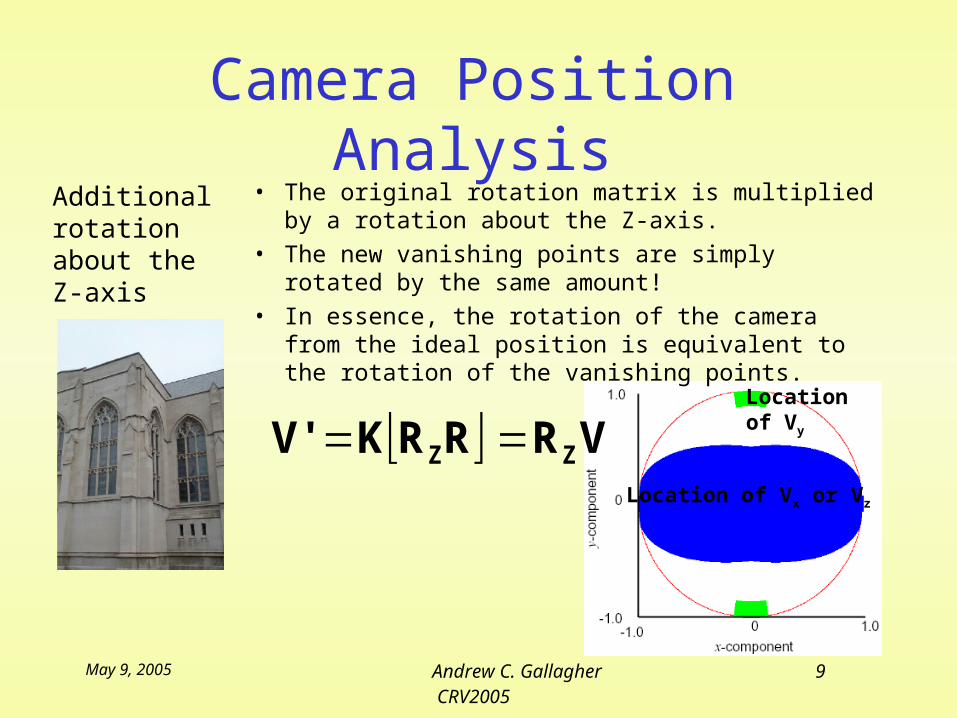
Camera Position Analysis Additional
rotation about the Z-axis
• The original rotation matrix is multiplied by a rotation about the Z-axis.
• The new vanishing points are simply rotated by the same amount!
• In essence, the rotation of the camera from the ideal position is equivalent to the rotation of the vanishing points.
VRRRKV' ZZ Location of Vx or Vz
Location of Vy
May 9, 2005 Andrew C. Gallagher10 CRV2005
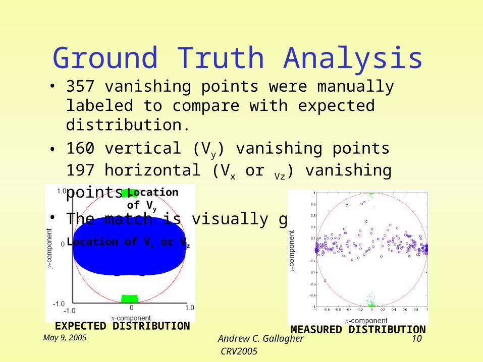
Ground Truth Analysis
Location of Vx or Vz
Location of Vy
• 357 vanishing points were manually labeled to compare with expected distribution.
• 160 vertical (Vy) vanishing points197 horizontal (Vx or Vz) vanishing points.
• The match is visually good.
EXPECTED DISTRIBUTION MEASURED DISTRIBUTION
May 9, 2005 Andrew C. Gallagher11 CRV2005
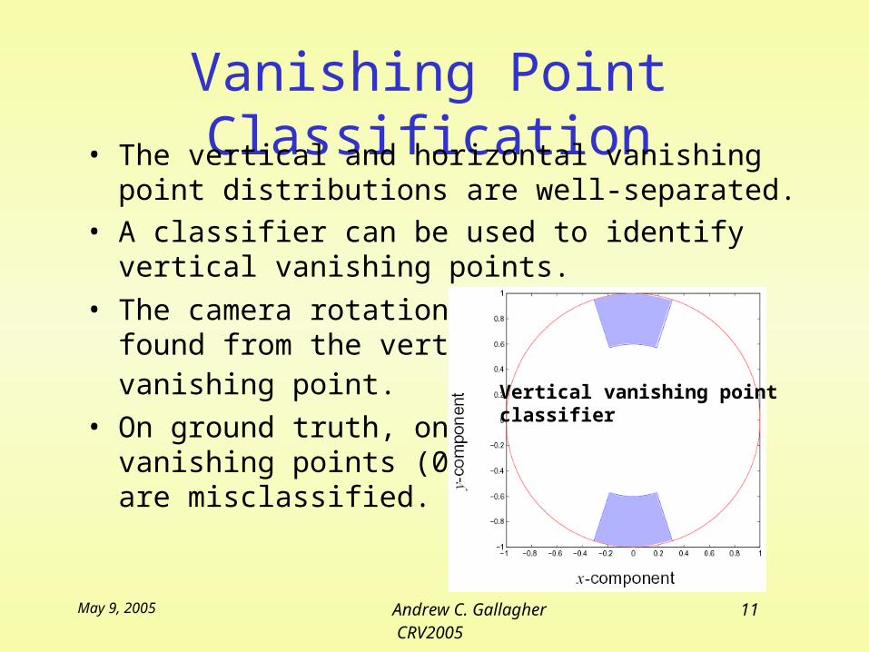
Vanishing Point Classification
• The vertical and horizontal vanishing point
distributions are well-separated. • A classifier can be used to identify vertical
vanishing points. • The camera rotation is
found from the vertical vanishing point.
• On ground truth, only 2vanishing points (0.6%)are misclassified.
Vertical vanishing pointclassifier
May 9, 2005 Andrew C. Gallagher12 CRV2005
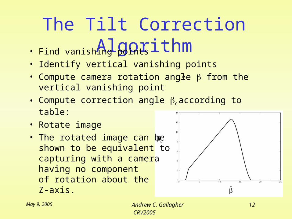
The Tilt Correction Algorithm
• Find vanishing points • Identify vertical vanishing points • Compute camera rotation angle from the
vertical vanishing point
• Compute correction angle c according to table:
• Rotate image• The rotated image can be
shown to be equivalent to capturing with a camerahaving no componentof rotation about the Z-axis.
^
May 9, 2005 Andrew C. Gallagher13 CRV2005
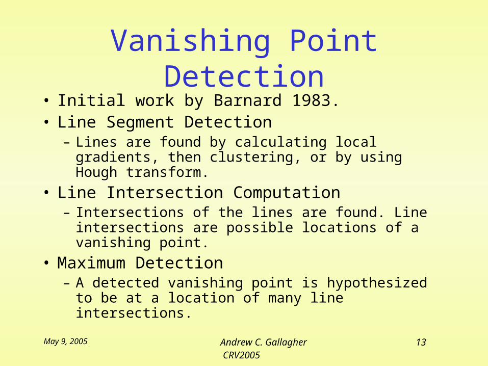
Vanishing Point Detection• Initial work by Barnard 1983.• Line Segment Detection
– Lines are found by calculating local gradients, then clustering, or by using Hough transform.
• Line Intersection Computation– Intersections of the lines are found. Line
intersections are possible locations of a vanishing point.
• Maximum Detection– A detected vanishing point is hypothesized to
be at a location of many line intersections.
May 9, 2005 Andrew C. Gallagher14 CRV2005
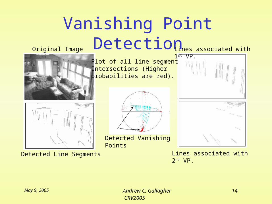
Vanishing Point DetectionOriginal Image
Detected Line Segments
Plot of all line segment Intersections (Higher probabilities are red).
Lines associated with 1st VP.
Lines associated with 2nd VP.
Detected Vanishing Points
May 9, 2005 Andrew C. Gallagher15 CRV2005
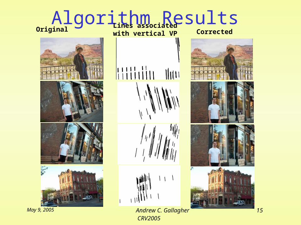
Algorithm Results Original Lines associated
with vertical VP Corrected
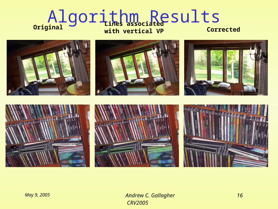
May 9, 2005 Andrew C. Gallagher16 CRV2005
Algorithm Results Original Lines associated
with vertical VP Corrected
May 9, 2005 Andrew C. Gallagher17 CRV2005
Conclusions• Rotation of the camera about the
principal axis moves the vertical vanishing point from the image y-axis.
• This novel algorithm corrects a tilted image by detecting the vertical vanishing point, and determining the magnitude of camera rotation.