Embed Size (px)
Citation preview
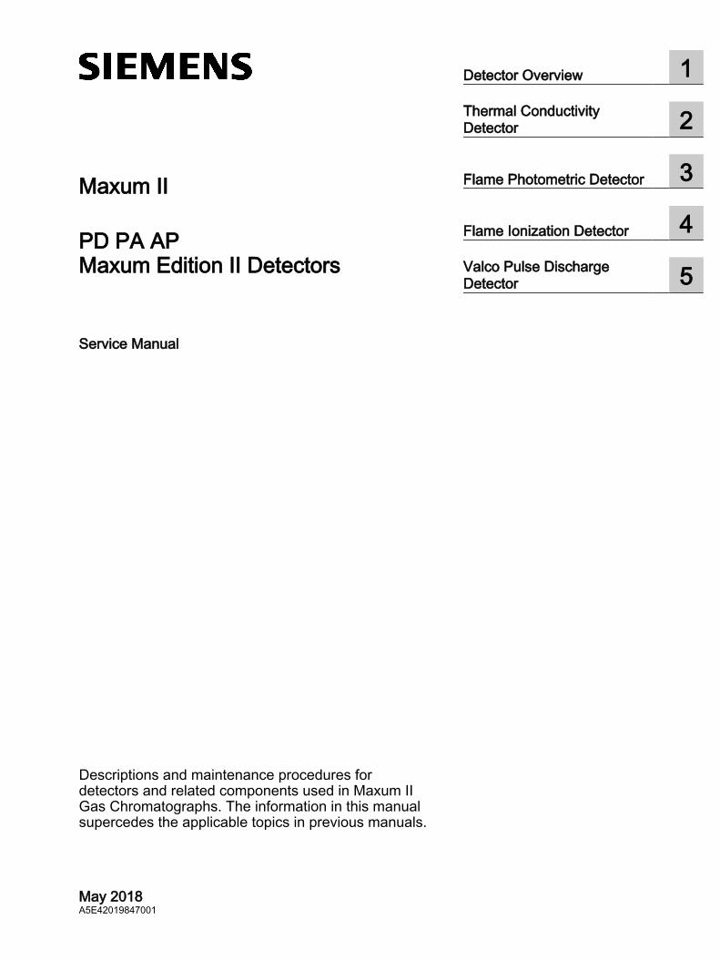
Maxum II
PD PA APMaxum Edition II Detectors
Service Manual
Descriptions and maintenance procedures for detectors and related components used in Maxum II Gas Chromatographs. The information in this manual supercedes the applicable topics in previous manuals.
May 2018A5E42019847001
Detector Overview 1Thermal Conductivity Detector 2
Flame Photometric Detector 3
Flame Ionization Detector 4Valco Pulse Discharge Detector 5
Legal informationWarning notice system
This manual contains notices you have to observe in order to ensure your personal safety, as well as to prevent damage to property. The notices referring to your personal safety are highlighted in the manual by a safety alert symbol, notices referring only to property damage have no safety alert symbol. These notices shown below are graded according to the degree of danger.
DANGERindicates that death or severe personal injury will result if proper precautions are not taken.
WARNINGindicates that death or severe personal injury may result if proper precautions are not taken.
CAUTIONindicates that minor personal injury can result if proper precautions are not taken.
NOTICEindicates that property damage can result if proper precautions are not taken.If more than one degree of danger is present, the warning notice representing the highest degree of danger will be used. A notice warning of injury to persons with a safety alert symbol may also include a warning relating to property damage.
Qualified PersonnelThe product/system described in this documentation may be operated only by personnel qualified for the specific task in accordance with the relevant documentation, in particular its warning notices and safety instructions. Qualified personnel are those who, based on their training and experience, are capable of identifying risks and avoiding potential hazards when working with these products/systems.
Proper use of Siemens productsNote the following:
WARNINGSiemens products may only be used for the applications described in the catalog and in the relevant technical documentation. If products and components from other manufacturers are used, these must be recommended or approved by Siemens. Proper transport, storage, installation, assembly, commissioning, operation and maintenance are required to ensure that the products operate safely and without any problems. The permissible ambient conditions must be complied with. The information in the relevant documentation must be observed.
TrademarksAll names identified by ® are registered trademarks of Siemens AG. The remaining trademarks in this publication may be trademarks whose use by third parties for their own purposes could violate the rights of the owner.
Disclaimer of LiabilityWe have reviewed the contents of this publication to ensure consistency with the hardware and software described. Since variance cannot be precluded entirely, we cannot guarantee full consistency. However, the information in this publication is reviewed regularly and any necessary corrections are included in subsequent editions.
Siemens AGDivision Process Industries and DrivesPostfach 48 4890026 NÜRNBERGGERMANY
A5E42019847001Ⓟ 05/2018 Subject to change
Copyright © Siemens AG 2018.All rights reserved
Table of contents
1 Detector Overview........................................................................................................................................5
1.1 DPM Types..............................................................................................................................5
2 Thermal Conductivity Detector.....................................................................................................................7
2.1 Intrinsically Safe Thermal Conductivity DPM...........................................................................8
2.2 Replacing TCD Components.................................................................................................112.2.1 Replace TCD Thermistor Beads/Filaments Introduction........................................................112.2.2 Procedure to Replace Thermistor Beads...............................................................................122.2.3 Replacing an IS-TCD DPM....................................................................................................13
2.3 TCD Specifications.................................................................................................................15
3 Flame Photometric Detector.......................................................................................................................17
3.1 Upgrade Description..............................................................................................................21
3.2 Intended Users.......................................................................................................................21
3.3 Safety and Certification Information.......................................................................................21
3.4 Procedure - Upgrade FPDI to FPDII......................................................................................22
3.5 Base3 Detector Personality Module (DPM)...........................................................................23
3.6 Base3DPM Status Indicator LEDs.........................................................................................28
3.7 Replacing a Base3DPM.........................................................................................................29
3.8 FPD Specifications.................................................................................................................30
4 Flame Ionization Detector...........................................................................................................................31
4.1 FID Maintenance Considerations...........................................................................................324.1.1 Intended Users.......................................................................................................................324.1.2 Safety and Certification Information.......................................................................................324.1.3 Available FID Repair Kits.......................................................................................................324.1.4 Purge Coil and Filter..............................................................................................................33
4.2 Replacing the FID Mesh Filter................................................................................................334.2.1 Procedure to Replace Mesh Filter..........................................................................................35
4.3 Replacing the FID Quartz Jet.................................................................................................364.3.1 Procedure to Replace Quartz Jet...........................................................................................36
4.4 Replacing the FID Igniter.......................................................................................................374.4.1 Procedure - Parts...................................................................................................................374.4.2 Procedure - Removing the Detector.......................................................................................384.4.3 Procedure - Igniter Replacement...........................................................................................424.4.4 Procedure - Reinstalling the Detector....................................................................................46
4.5 FID Specifications..................................................................................................................47
4.6 Filament Detector...................................................................................................................484.6.1 Replacing the Filaments.........................................................................................................50
Maxum Edition II DetectorsService Manual, May 2018, A5E42019847001 3
4.7 Methanator.............................................................................................................................514.7.1 Methanator Function..............................................................................................................514.7.2 Purged Methanator................................................................................................................524.7.3 Explosion-Proof Methanator...................................................................................................534.7.4 Methanator Specifications......................................................................................................534.7.5 Methanator Maintenance Considerations..............................................................................54
4.8 Air Treater..............................................................................................................................554.8.1 Air Treater Maintenance Considerations................................................................................554.8.2 Air Treater Specifications.......................................................................................................56
5 Valco Pulse Discharge Detector.................................................................................................................57
5.1 PDD Specifications................................................................................................................57
Table of contents
Maxum Edition II Detectors4 Service Manual, May 2018, A5E42019847001
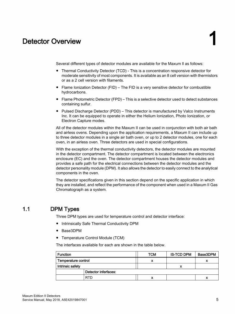
Detector Overview 1Several different types of detector modules are available for the Maxum ll as follows:
● Thermal Conductivity Detector (TCD) - This is a concentration responsive detector for moderate sensitivity of most components. It is available as an 8 cell version with thermistors or as a 2 cell version with filaments.
● Flame Ionization Detector (FID) – The FID is a very sensitive detector for combustible hydrocarbons.
● Flame Photometric Detector (FPD) – This is a selective detector used to detect substances containing sulfur.
● Pulsed Discharge Detector (PDD) – This detector is manufactured by Valco Instruments Inc. It can be equipped to operate in either the Helium Ionization, Photo Ionization, or Electron Capture modes.
All of the detector modules within the Maxum II can be used in conjunction with both air bath and airless ovens. Depending upon the application requirements, a Maxum II can include up to three detector modules in a single air bath oven, or up to 2 detector modules, one for each oven, in an airless oven. Three detectors are used in special configurations.
With the exception of the thermal conductivity detectors, the detector modules are mounted in the detector compartment. The detector compartment is located between the electronics enclosure (EC) and the oven. The detector compartment houses the detector modules and provides a safe path for the electrical connections between the detector modules and the detector personality module (DPM). It also allows the detector to easily connect to the analytical components in the oven.
The detector specifications given in this section depend on the specific application in which they are installed, and reflect the performance of the component when used in a Maxum II Gas Chromatograph as a system.
1.1 DPM TypesThree DPM types are used for temperature control and detector interface:
● Intrinsically Safe Thermal Conductivity DPM
● Base3DPM
● Temperature Control Module (TCM)
The interfaces available for each are shown in the table below.
Function TCM IS-TCD DPM Base3DPMTemperature control x xIntrinsic safety x
Detector inferfaces: RTD x x
Maxum Edition II DetectorsService Manual, May 2018, A5E42019847001 5

Function TCM IS-TCD DPM Base3DPM Thermistor x Filament x FID x FPD x VPD x
Detector Overview1.1 DPM Types
Maxum Edition II Detectors6 Service Manual, May 2018, A5E42019847001
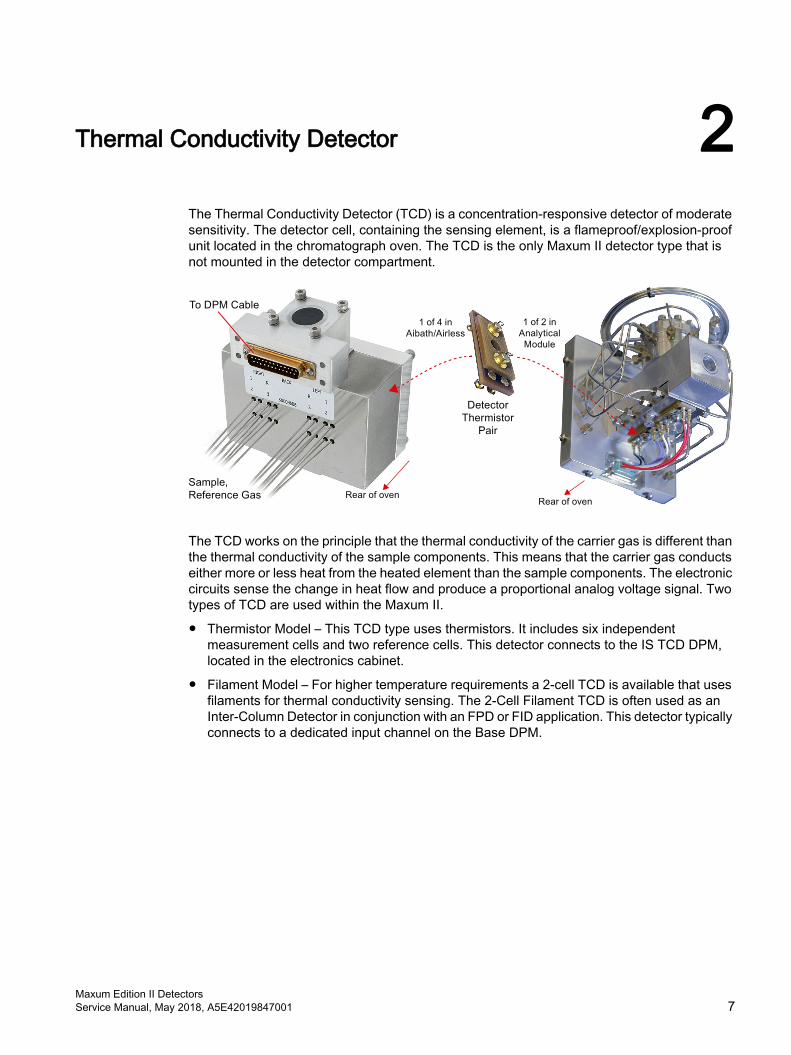
Thermal Conductivity Detector 2The Thermal Conductivity Detector (TCD) is a concentration-responsive detector of moderate sensitivity. The detector cell, containing the sensing element, is a flameproof/explosion-proof unit located in the chromatograph oven. The TCD is the only Maxum II detector type that is not mounted in the detector compartment.
The TCD works on the principle that the thermal conductivity of the carrier gas is different than the thermal conductivity of the sample components. This means that the carrier gas conducts either more or less heat from the heated element than the sample components. The electronic circuits sense the change in heat flow and produce a proportional analog voltage signal. Two types of TCD are used within the Maxum II.
● Thermistor Model – This TCD type uses thermistors. It includes six independent measurement cells and two reference cells. This detector connects to the IS TCD DPM, located in the electronics cabinet.
● Filament Model – For higher temperature requirements a 2-cell TCD is available that uses filaments for thermal conductivity sensing. The 2-Cell Filament TCD is often used as an Inter‑Column Detector in conjunction with an FPD or FID application. This detector typically connects to a dedicated input channel on the Base DPM.
Maxum Edition II DetectorsService Manual, May 2018, A5E42019847001 7
2.1 Intrinsically Safe Thermal Conductivity DPM
OverviewOutput signals from the Thermal Conductivity Detector (TCD) in the oven are wired to the associated Detector Personality Module (DPM). The DPM is mounted inside the Electronics Compartment (EC) on the floor of the compartment. The DPM digitizes the incoming analog signal and then passes the data to the system controller via an I2C port. The resulting data is then processed by the Embedded SNE software. Results can then be viewed on the maintenance panel or the workstation.
TCD Beads
(thermistor)
IS-TCD
DPM
(A/D)
PECMSYSCON
Color
Touch
Display
GCP
AnalogI2CI2CNetwork
Figure 2-1 Thermal Conductivity Detector Signal Path
The IS TCD DPM is an enclosed unit that is not field repairable. Opening the case voids the safety protection of the device. Service is limited to replacement of the entire DPM.
Part NumbersThe IS TCD4 DPM is compatible with the MAXUM Airbath and Airless platforms for Intrinsically Safe and non-Intrinsically Safe detectors. Where an Intrinsically Safe TCD is used, the safety certification for the MAXUM Airbath and Airless only allow the IS TCD4 DPM. The IS TCD3 DPM is ONLY certified for use with an Intrinsically Safe detector in the Maxum Modular Oven model. (Both IS TCD3 DPM and IS TCD4 DPM are certified for use in the Maxum Modular Oven model). The Maxum Airbath and Airless models that use an Intrinsically Safe detector are certified only when an IS TCD4 DPM is properly installed.
The IS TCD4 DPM (part number A5E43267455001) is installed in current analyzers. The IS TCD3 DPM cannot be used as a replacement for the IS TCD4 DPM. See the note under the Connections heading.
The IS TCD3 DPM (part number A5E02645923001) can be used as a replacement part for earlier DPMs in Maxum I analyzers using an adapter, part number A5E34938550001. See the publication IP-0034: Procedure to Replace Various TCD DPMs with Paired IS TCD DPM and TC DPM in a Maxum or Maxum II Analyzer on the Siemens web site.
Intrinsic SafetyThe intrinsic safety feature of this module was not used in early versions of the Maxum II Airless and Airbath Oven model. The following two paragraphs apply only if this feature is used.
The TCD DPM in the Maxum II, as well as the actual detector controlled by the TCD, is protected by intrinsic safety. Intrinsic safety is a method of protection where a circuit is designed such that it will not create a spark or other condition capable of causing ignition of flammable
Thermal Conductivity Detector2.1 Intrinsically Safe Thermal Conductivity DPM
Maxum Edition II Detectors8 Service Manual, May 2018, A5E42019847001
vapors or gases, even under fault conditions. Various circuits in the Maxum analyzer use this form of protection, including the IS TCD.
WARNING
Observe Intrinsic Safety practices
To preserve the intrinsically safe design protection of the IS TCD, certain measures are required. Failure to adhere to all requirements for use of the IS TCD in the Maxum II could violate the safety protections of the analyzer and cause equipment damage or serious injury. See the Maxum II Explosion Protection Safety Standards Manual (A5E02220442001) (https://support.industry.siemens.com/cs/document/42017542/maxum-edition-ii%3A-explosion-protection-safety-standards?lc=en-WW&pnid=17741) for more information on the safe use of intrinsically safe circuitry in the Maxum II.
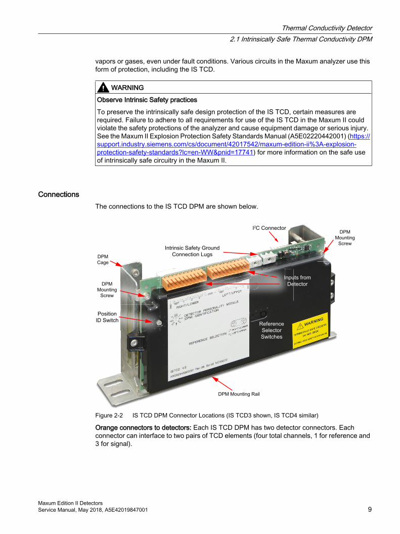
ConnectionsThe connections to the IS TCD DPM are shown below.
DPM
Mounting
Screw
DPM Mounting Rail
DPM
Mounting
Screw
DPM
Cage
Reference
Selector
Switches
I2C Connector
Intrinsic Safety Ground
Connection Lugs
Position
ID Switch
Inputs from
Detector
Figure 2-2 IS TCD DPM Connector Locations (IS TCD3 shown, IS TCD4 similar)
Orange connectors to detectors: Each IS TCD DPM has two detector connectors. Each connector can interface to two pairs of TCD elements (four total channels, 1 for reference and 3 for signal).
Thermal Conductivity Detector2.1 Intrinsically Safe Thermal Conductivity DPM
Maxum Edition II DetectorsService Manual, May 2018, A5E42019847001 9
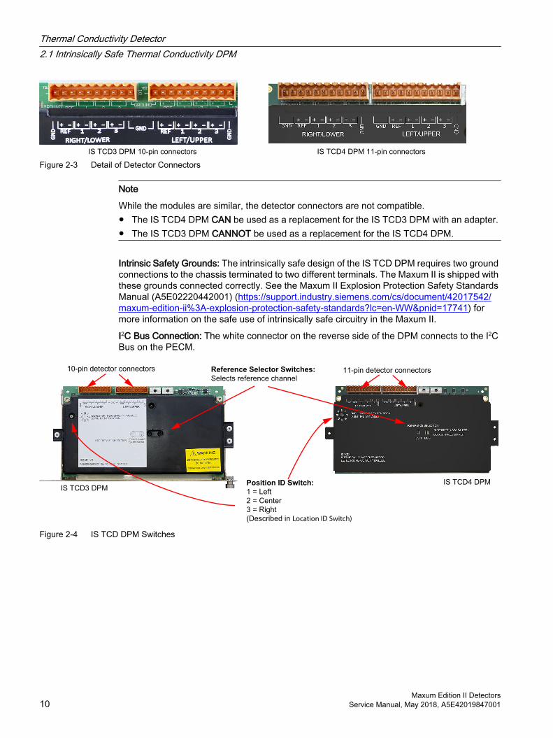
Figure 2-3 Detail of Detector Connectors
Note
While the modules are similar, the detector connectors are not compatible. ● The IS TCD4 DPM CAN be used as a replacement for the IS TCD3 DPM with an adapter. ● The IS TCD3 DPM CANNOT be used as a replacement for the IS TCD4 DPM.
Intrinsic Safety Grounds: The intrinsically safe design of the IS TCD DPM requires two ground connections to the chassis terminated to two different terminals. The Maxum II is shipped with these grounds connected correctly. See the Maxum II Explosion Protection Safety Standards Manual (A5E02220442001) (https://support.industry.siemens.com/cs/document/42017542/maxum-edition-ii%3A-explosion-protection-safety-standards?lc=en-WW&pnid=17741) for more information on the safe use of intrinsically safe circuitry in the Maxum II.
I2C Bus Connection: The white connector on the reverse side of the DPM connects to the I2C Bus on the PECM.
Reference Selector Switches:
Selects reference channel
Position ID Switch:
1 = Left
2 = Center
3 = Right
(Described in Location ID Switch)
Figure 2-4 IS TCD DPM Switches
Thermal Conductivity Detector2.1 Intrinsically Safe Thermal Conductivity DPM
Maxum Edition II Detectors10 Service Manual, May 2018, A5E42019847001
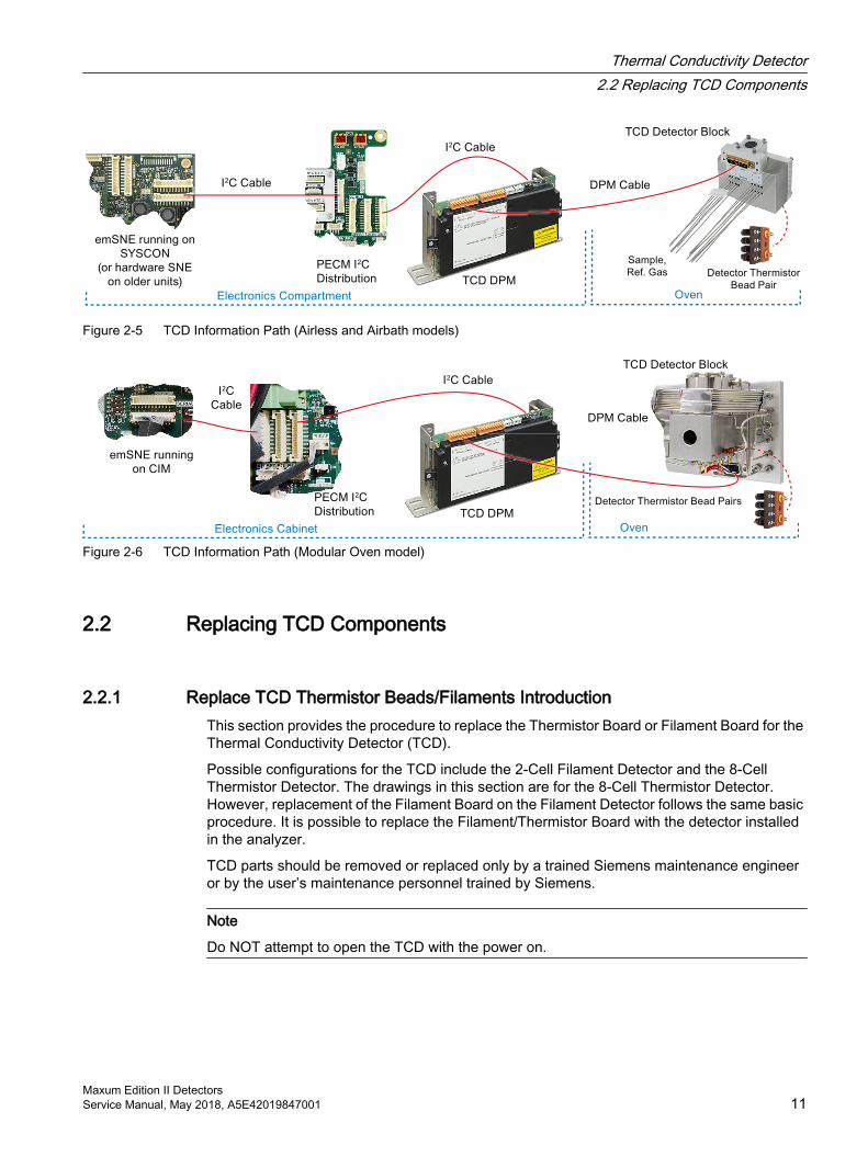
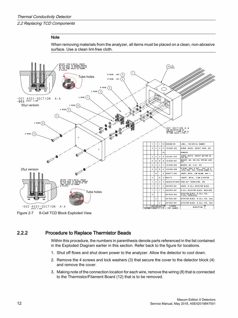
Figure 2-5 TCD Information Path (Airless and Airbath models)
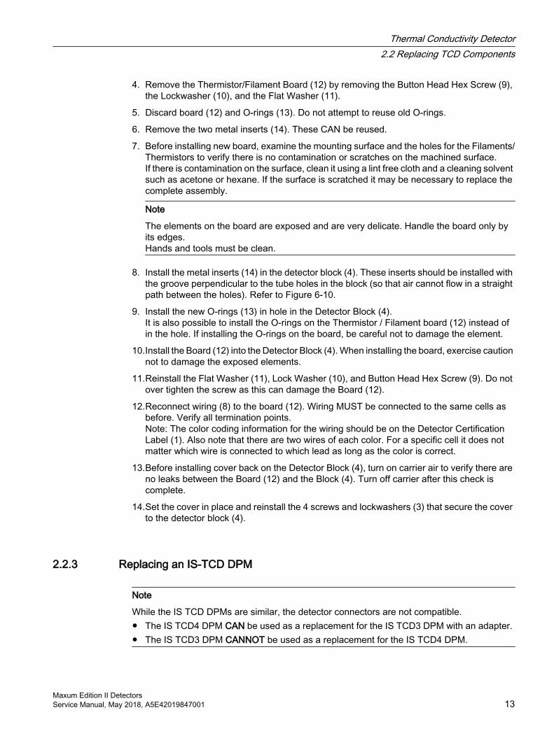
Figure 2-6 TCD Information Path (Modular Oven model)
2.2 Replacing TCD Components
2.2.1 Replace TCD Thermistor Beads/Filaments IntroductionThis section provides the procedure to replace the Thermistor Board or Filament Board for the Thermal Conductivity Detector (TCD).
Possible configurations for the TCD include the 2-Cell Filament Detector and the 8-Cell Thermistor Detector. The drawings in this section are for the 8-Cell Thermistor Detector. However, replacement of the Filament Board on the Filament Detector follows the same basic procedure. It is possible to replace the Filament/Thermistor Board with the detector installed in the analyzer.
TCD parts should be removed or replaced only by a trained Siemens maintenance engineer or by the user’s maintenance personnel trained by Siemens.
Note
Do NOT attempt to open the TCD with the power on.
Thermal Conductivity Detector2.2 Replacing TCD Components
Maxum Edition II DetectorsService Manual, May 2018, A5E42019847001 11
Note
When removing materials from the analyzer, all items must be placed on a clean, non-abrasive surface. Use a clean lint-free cloth.
µ
µ
Figure 2-7 8-Cell TCD Block Exploded View
2.2.2 Procedure to Replace Thermistor BeadsWithin this procedure, the numbers in parenthesis denote parts referenced in the list contained in the Exploded Diagram earlier in this section. Refer back to the figure for locations.
1. Shut off flows and shut down power to the analyzer. Allow the detector to cool down.
2. Remove the 4 screws and lock washers (3) that secure the cover to the detector block (4) and remove the cover.
3. Making note of the connection location for each wire, remove the wiring (8) that is connected to the Thermistor/Filament Board (12) that is to be removed.
Thermal Conductivity Detector2.2 Replacing TCD Components
Maxum Edition II Detectors12 Service Manual, May 2018, A5E42019847001
4. Remove the Thermistor/Filament Board (12) by removing the Button Head Hex Screw (9), the Lockwasher (10), and the Flat Washer (11).
5. Discard board (12) and O-rings (13). Do not attempt to reuse old O-rings.
6. Remove the two metal inserts (14). These CAN be reused.
7. Before installing new board, examine the mounting surface and the holes for the Filaments/Thermistors to verify there is no contamination or scratches on the machined surface.If there is contamination on the surface, clean it using a lint free cloth and a cleaning solvent such as acetone or hexane. If the surface is scratched it may be necessary to replace the complete assembly.
Note
The elements on the board are exposed and are very delicate. Handle the board only by its edges.Hands and tools must be clean.
8. Install the metal inserts (14) in the detector block (4). These inserts should be installed with the groove perpendicular to the tube holes in the block (so that air cannot flow in a straight path between the holes). Refer to Figure 6-10.
9. Install the new O-rings (13) in hole in the Detector Block (4).It is also possible to install the O-rings on the Thermistor / Filament board (12) instead of in the hole. If installing the O-rings on the board, be careful not to damage the element.
10.Install the Board (12) into the Detector Block (4). When installing the board, exercise caution not to damage the exposed elements.
11.Reinstall the Flat Washer (11), Lock Washer (10), and Button Head Hex Screw (9). Do not over tighten the screw as this can damage the Board (12).
12.Reconnect wiring (8) to the board (12). Wiring MUST be connected to the same cells as before. Verify all termination points.Note: The color coding information for the wiring should be on the Detector Certification Label (1). Also note that there are two wires of each color. For a specific cell it does not matter which wire is connected to which lead as long as the color is correct.
13.Before installing cover back on the Detector Block (4), turn on carrier air to verify there are no leaks between the Board (12) and the Block (4). Turn off carrier after this check is complete.
14.Set the cover in place and reinstall the 4 screws and lockwashers (3) that secure the cover to the detector block (4).
2.2.3 Replacing an IS-TCD DPM
Note
While the IS TCD DPMs are similar, the detector connectors are not compatible. ● The IS TCD4 DPM CAN be used as a replacement for the IS TCD3 DPM with an adapter. ● The IS TCD3 DPM CANNOT be used as a replacement for the IS TCD4 DPM.
Thermal Conductivity Detector2.2 Replacing TCD Components
Maxum Edition II DetectorsService Manual, May 2018, A5E42019847001 13
Removing the IS TCD DPMSee the illustration IS TCD DPM Connector Locations for connector locations.
1. Back up and shut down the unit using the General Analyzer Shutdown Procedure in the Maxum Edition II Analyzer General Maintenance Manual.
2. Open the electronics enclosure door.
3. Disconnect the detector cables by unplugging the orange connectors.
4. Disconnect the I2C/power cable.
5. If present, take out screws holding the IS ground cables.
6. Remove the nut on the bottom-front of DPM bracket.
7. Slide the unit forward to disengage the rear mounting lug.
8. Lift the unit up and out of the enclosure and place on an ESD-safe work surface.
9. Remove the two mounting screws near the upper corners and remove the old unit from the DPM cage.
Configuring the New IS TCD DPMSet the location ID switch and reference-selector switches on the replacement unit to match those on the unit being removed.
Note
For the reference-selector switches, the IS TCD4 DPM uses slide switches in place of the 2-position rotary switches on older units. The function is the same.
Installing the Replacement IS TCD DPM1. Install the new unit into the DPM cage. Insert the bottom edge into the slot in the plastic
DPM mounting rail on the DPM cage, and secure with the two screws removed from the old unit.
2. Insert the rear lug into the slot at the rear of the DPM mounting position with the mounting stud at the front inserted through the slot in the DPM bracket.
3. Slide backward to lock the rear mounting lug into the slot.
4. Reinstall the nut on the threaded stud to secure the DPM.
5. Reconnect the I2C/power cable.
6. Reconnect the IS ground cables if used.
7. Reconnect the detector cables.
8. Follow the steps in the General Analyzer Startup Procedure in the Maxum Edition II Analyzer General Maintenance Manual.
Thermal Conductivity Detector2.2 Replacing TCD Components
Maxum Edition II Detectors14 Service Manual, May 2018, A5E42019847001
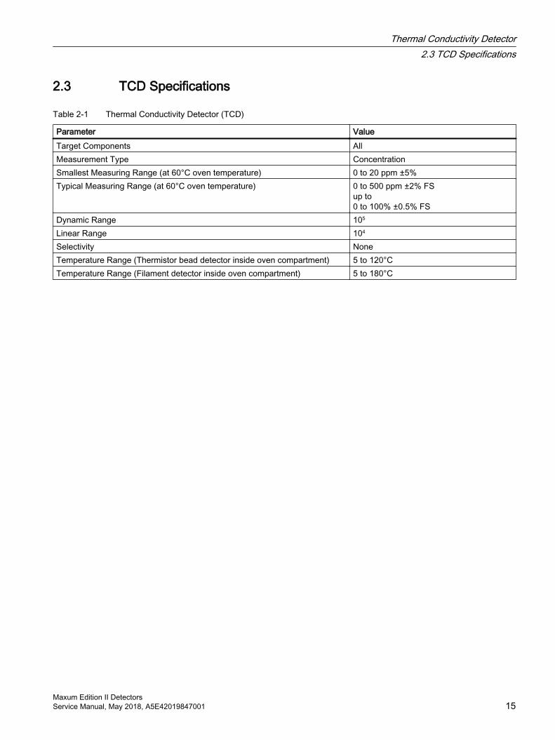
2.3 TCD Specifications
Table 2-1 Thermal Conductivity Detector (TCD)
Parameter ValueTarget Components AllMeasurement Type ConcentrationSmallest Measuring Range (at 60°C oven temperature) 0 to 20 ppm ±5%Typical Measuring Range (at 60°C oven temperature) 0 to 500 ppm ±2% FS
up to 0 to 100% ±0.5% FS
Dynamic Range 105
Linear Range 104
Selectivity NoneTemperature Range (Thermistor bead detector inside oven compartment) 5 to 120°C Temperature Range (Filament detector inside oven compartment) 5 to 180°C
Thermal Conductivity Detector2.3 TCD Specifications
Maxum Edition II DetectorsService Manual, May 2018, A5E42019847001 15

Thermal Conductivity Detector2.3 TCD Specifications
Maxum Edition II Detectors16 Service Manual, May 2018, A5E42019847001
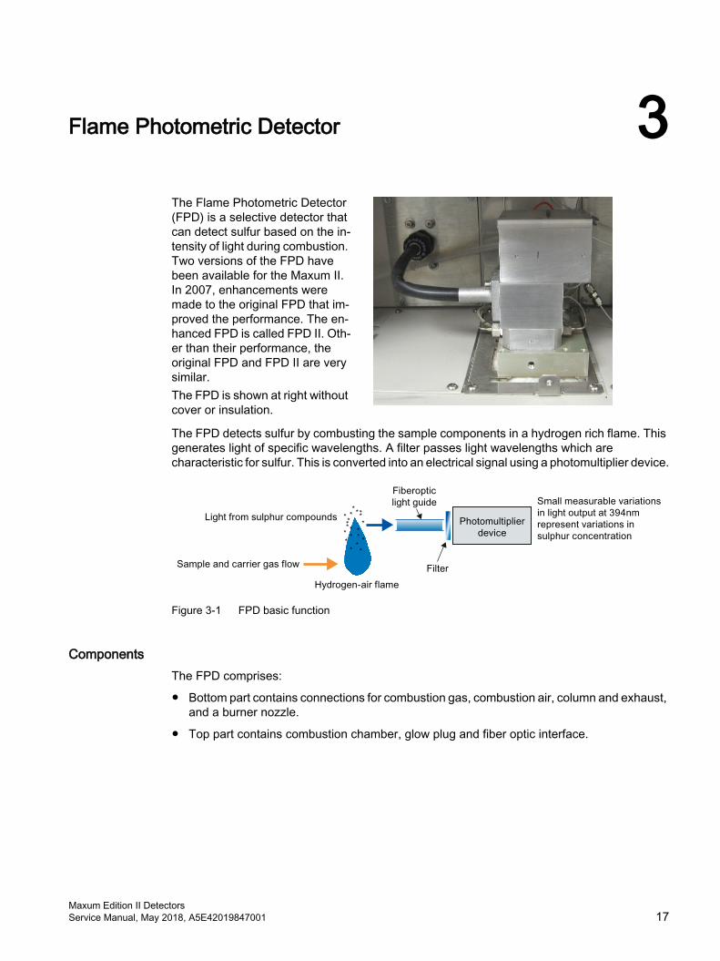
Flame Photometric Detector 3The Flame Photometric Detector (FPD) is a selective detector that can detect sulfur based on the in‐tensity of light during combustion. Two versions of the FPD have been available for the Maxum II. In 2007, enhancements were made to the original FPD that im‐proved the performance. The en‐hanced FPD is called FPD II. Oth‐er than their performance, the original FPD and FPD II are very similar.The FPD is shown at right without cover or insulation.
The FPD detects sulfur by combusting the sample components in a hydrogen rich flame. This generates light of specific wavelengths. A filter passes light wavelengths which are characteristic for sulfur. This is converted into an electrical signal using a photomultiplier device.
Figure 3-1 FPD basic function
ComponentsThe FPD comprises:
● Bottom part contains connections for combustion gas, combustion air, column and exhaust, and a burner nozzle.
● Top part contains combustion chamber, glow plug and fiber optic interface.
Maxum Edition II DetectorsService Manual, May 2018, A5E42019847001 17
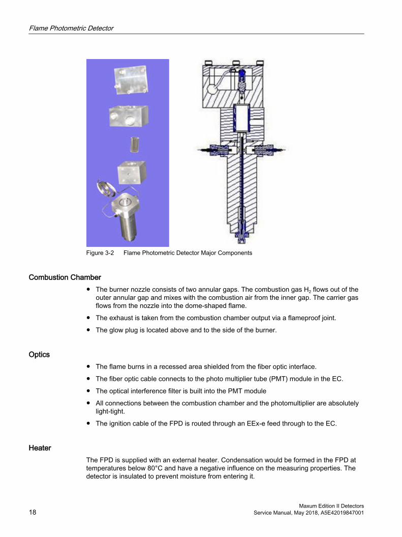
Figure 3-2 Flame Photometric Detector Major Components
Combustion Chamber● The burner nozzle consists of two annular gaps. The combustion gas H2 flows out of the
outer annular gap and mixes with the combustion air from the inner gap. The carrier gas flows from the nozzle into the dome-shaped flame.
● The exhaust is taken from the combustion chamber output via a flameproof joint.
● The glow plug is located above and to the side of the burner.
Optics● The flame burns in a recessed area shielded from the fiber optic interface.
● The fiber optic cable connects to the photo multiplier tube (PMT) module in the EC.
● The optical interference filter is built into the PMT module
● All connections between the combustion chamber and the photomultiplier are absolutely light-tight.
● The ignition cable of the FPD is routed through an EEx-e feed through to the EC.
HeaterThe FPD is supplied with an external heater. Condensation would be formed in the FPD at temperatures below 80°C and have a negative influence on the measuring properties. The detector is insulated to prevent moisture from entering it.
Flame Photometric Detector
Maxum Edition II Detectors18 Service Manual, May 2018, A5E42019847001
The detector temperature is factory set depending upon the application. The temperature is normally set equal to or higher than the oven temperature and at minimum 80°C.
Detector Gas SupplyFor information on detector gas-supply requirements. see the Maxum II Official Product Specifications (A5E03012338001) (https://support.industry.siemens.com/cs/document/42017542/maxum-edition-ii%3A-explosion-protection-safety-standards?lc=en-WW&pnid=17741). This publication gives approximate requirements. Specific requirements depend on the application.
Note
The FPD is a very sensitive detector. The gases and their supply lines must be extremely clean and sulfur free to achieve a high signal/noise ratio.
Selection of Carrier GasNitrogen, helium, argon or hydrogen can be used as the carrier gas. If hydrogen carrier is used, the required flow of hydrogen flame fuel will be reduced. For the FPD II, the total hydrogen flow (combined flame fuel and carrier) will be ~100-130 mL/min.
Flame Photometric Detector
Maxum Edition II DetectorsService Manual, May 2018, A5E42019847001 19
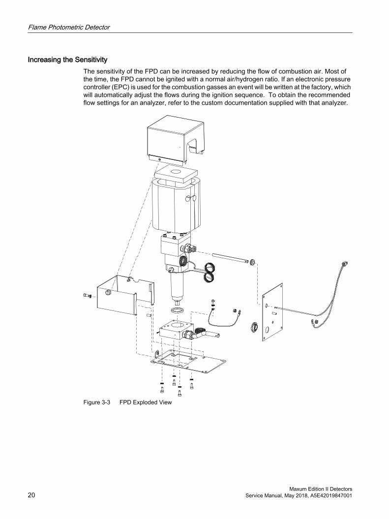
Increasing the SensitivityThe sensitivity of the FPD can be increased by reducing the flow of combustion air. Most of the time, the FPD cannot be ignited with a normal air/hydrogen ratio. If an electronic pressure controller (EPC) is used for the combustion gasses an event will be written at the factory, which will automatically adjust the flows during the ignition sequence. To obtain the recommended flow settings for an analyzer, refer to the custom documentation supplied with that analyzer.
Figure 3-3 FPD Exploded View
Flame Photometric Detector
Maxum Edition II Detectors20 Service Manual, May 2018, A5E42019847001
3.1 Upgrade DescriptionThis section describes the procedure to replace the original Flame Photometric Detector (FPD) in the Maxum II with a newer version FPD. This involves replacing the FPD assembly, called FPD I, with the new FPD assembly, called FPD II. The existing light pipe and photomultiplier tube from the FPD I will be reused. It will be necessary to power down the analyzer for this procedure.
The Flame Photometric Detector (FPD) is a selective detector that can detect sulfur based on the emission of light during combustion. In 2007 a new version of the FPD was released for the Maxum II. The original version is now known as FPD I. The new version is called FPD II. The FPD II is a more sensitive and more consistent detector than the FPD I.
3.2 Intended UsersThis procedure is intended for either Siemens personnel or for highly skilled users who have been trained by Siemens to perform this type of procedure. Users of this procedure must have strong working knowledge of the safety systems of the Maxum II analyzer and have the knowledge to safely power the analyzer down and back up. Users must also have a good working knowledge of the Maxum II hardware and should be very familiar with the operation and day to day maintenance of the analyzer.
This procedure involves replacement of the Flame Photometric Detector which may impact the safety protection of the analyzer. This procedure should only be executed with the approval of applicable local safety personnel and/or the local authority having jurisdiction.
3.3 Safety and Certification InformationThis retrofit may impact the safety protection of the analyzer. This procedure involves a retrofit of the Flame Photometric Detector (FPD). The FPD is an explosion-proof device that is equipped with required safety systems. It is important that these safety systems not be compromised. All instructions and warnings in this procedure must be followed.
Maintenance work on the Maxum II analyzer should only be performed when the area is known to be safe for the work to be done.
Note
This procedure must only be executed with the consent and approval of all applicable local safety personnel and/or the local authority having jurisdiction.
Conditions for Safe Use per ATEX Certificate● The FPD shall be protected against mechanical damage by mounting inside another
enclosure.
● The relative maximal pressure existing inside the flameproof enclosure shall not exceed 0.065 bar.
Flame Photometric Detector3.3 Safety and Certification Information
Maxum Edition II DetectorsService Manual, May 2018, A5E42019847001 21
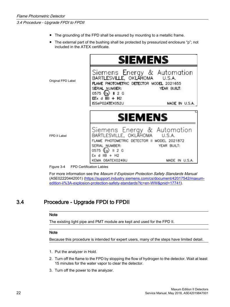
● The grounding of the FPD shall be ensured by mounting to a metallic frame.
● The external part of the bushing shall be protected by pressurized enclosure “p”; not included in the ATEX certificate.
Original FPD Label
FPD II Label
Figure 3-4 FPD Certification Lables
For more information see the Maxum II Explosion Protection Safety Standards Manual (A5E02220442001) (https://support.industry.siemens.com/cs/document/42017542/maxum-edition-ii%3A-explosion-protection-safety-standards?lc=en-WW&pnid=17741).
3.4 Procedure - Upgrade FPDI to FPDII
Note
The existing light pipe and PMT module are kept and used for the FPD II.
Note
Because this procedure is intended for expert users, many of the steps have limited detail.
1. Put the analyzer in Hold.
2. Turn off the flame to the FPD by stopping the flow of hydrogen to the detector. Wait at least 15 minutes for the water vapor to clear the detector.
3. Turn off the power to the analyzer.
Flame Photometric Detector3.4 Procedure - Upgrade FPDI to FPDII
Maxum Edition II Detectors22 Service Manual, May 2018, A5E42019847001
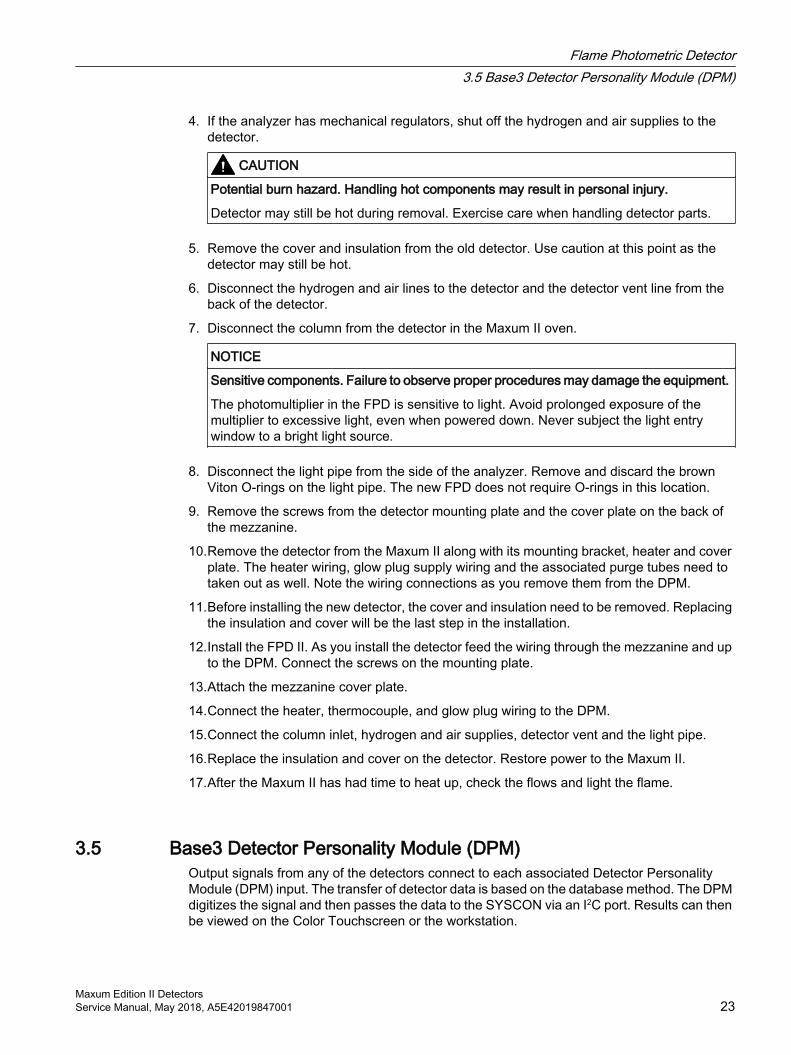
4. If the analyzer has mechanical regulators, shut off the hydrogen and air supplies to the detector.
CAUTION
Potential burn hazard. Handling hot components may result in personal injury.
Detector may still be hot during removal. Exercise care when handling detector parts.
5. Remove the cover and insulation from the old detector. Use caution at this point as the detector may still be hot.
6. Disconnect the hydrogen and air lines to the detector and the detector vent line from the back of the detector.
7. Disconnect the column from the detector in the Maxum II oven.
NOTICE
Sensitive components. Failure to observe proper procedures may damage the equipment.
The photomultiplier in the FPD is sensitive to light. Avoid prolonged exposure of the multiplier to excessive light, even when powered down. Never subject the light entry window to a bright light source.
8. Disconnect the light pipe from the side of the analyzer. Remove and discard the brown Viton O-rings on the light pipe. The new FPD does not require O-rings in this location.
9. Remove the screws from the detector mounting plate and the cover plate on the back of the mezzanine.
10.Remove the detector from the Maxum II along with its mounting bracket, heater and cover plate. The heater wiring, glow plug supply wiring and the associated purge tubes need to taken out as well. Note the wiring connections as you remove them from the DPM.
11.Before installing the new detector, the cover and insulation need to be removed. Replacing the insulation and cover will be the last step in the installation.
12.Install the FPD II. As you install the detector feed the wiring through the mezzanine and up to the DPM. Connect the screws on the mounting plate.
13.Attach the mezzanine cover plate.
14.Connect the heater, thermocouple, and glow plug wiring to the DPM.
15.Connect the column inlet, hydrogen and air supplies, detector vent and the light pipe.
16.Replace the insulation and cover on the detector. Restore power to the Maxum II.
17.After the Maxum II has had time to heat up, check the flows and light the flame.
3.5 Base3 Detector Personality Module (DPM)Output signals from any of the detectors connect to each associated Detector Personality Module (DPM) input. The transfer of detector data is based on the database method. The DPM digitizes the signal and then passes the data to the SYSCON via an I2C port. Results can then be viewed on the Color Touchscreen or the workstation.
Flame Photometric Detector3.5 Base3 Detector Personality Module (DPM)
Maxum Edition II DetectorsService Manual, May 2018, A5E42019847001 23
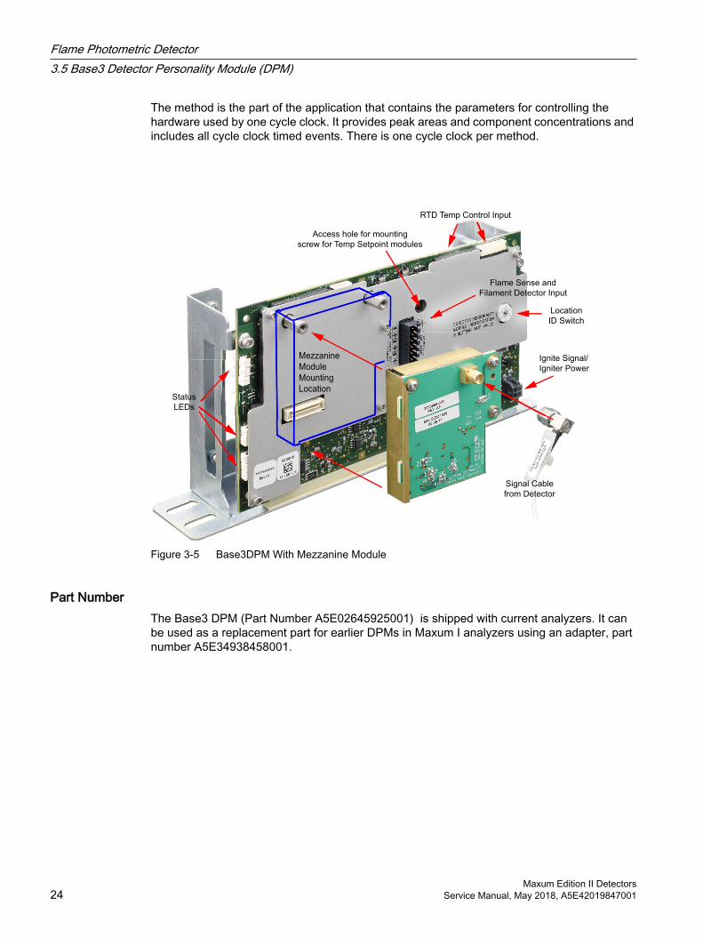
The method is the part of the application that contains the parameters for controlling the hardware used by one cycle clock. It provides peak areas and component concentrations and includes all cycle clock timed events. There is one cycle clock per method.
Status
LEDs
Access hole for mounting
screw for Temp Setpoint modules
Ignite Signal/
Igniter Power
Location
ID Switch
RTD Temp Control Input
Flame Sense and
Filament Detector Input
Signal Cable
from Detector
Mezzanine
Module
Mounting
Location
Figure 3-5 Base3DPM With Mezzanine Module
Part NumberThe Base3 DPM (Part Number A5E02645925001) is shipped with current analyzers. It can be used as a replacement part for earlier DPMs in Maxum I analyzers using an adapter, part number A5E34938458001.
Flame Photometric Detector3.5 Base3 Detector Personality Module (DPM)
Maxum Edition II Detectors24 Service Manual, May 2018, A5E42019847001
Overview of DPM FunctionsThe Base 3 Detector Personality Module (DPM) combines these functions in a single module:
Including Mezzanine Modules
FID
Input from detector via mezzanine moduleIgnite signal / glow-plug outputRange-select output300-V bias outputFlame-sense input (used in Maxum I analyzers only)
FPD
Input from detector via mezzanine moduleIgnite signal / glow-plug outputRange-select outputEnable signal output300V bias outputFlame-sense input (used in Maxum I analyzers only)
Analog volt‐
age input
Input from detector via mezzanine moduleRange-select output
Filament Detector Input via connector on right side (as viewed inside analyzer EC)
Temperature control
Temperature setpoint module connectorTwo RTD inputsTwo heater-control outputs
System communication I2C port with ID-select switch
Input Signal PathsThe input-signal functions are shown below.
Analog Flame Ionization or
Flame Photometric
Detector
Network I2C I2C Analog
GCP
Color
Touch
Display
SYSCON PECMBaseDPM
A/D
Mezzanine
Module
(signal conditioning)
Figure 3-6 FID, FPD, or Analog Input Detector Input Signal Path
NetworkI2C I2C
Analog
GCP
Color
Touch
Display
SYSCON PECMBaseDPM
A/D
Filament
Detector
Figure 3-7 Filament Detector Input Signal Path
Flame Photometric Detector3.5 Base3 Detector Personality Module (DPM)
Maxum Edition II DetectorsService Manual, May 2018, A5E42019847001 25
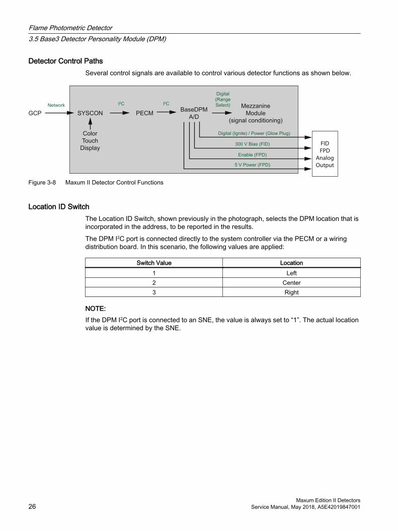
Detector Control PathsSeveral control signals are available to control various detector functions as shown below.
5 V Power (FPD)
Enable (FPD)
300 V Bias (FID)
Digital (Ignite) / Power (Glow Plug)
Network I2C I2C
Digital
(Range
Select)
GCP
Color
Touch
Display
SYSCON PECMBaseDPM
A/D
Mezzanine
Module
(signal conditioning)
FID
FPD
Analog
Output
Figure 3-8 Maxum II Detector Control Functions
Location ID SwitchThe Location ID Switch, shown previously in the photograph, selects the DPM location that is incorporated in the address, to be reported in the results.
The DPM I2C port is connected directly to the system controller via the PECM or a wiring distribution board. In this scenario, the following values are applied:
Switch Value Location1 Left2 Center3 Right
NOTE:If the DPM I2C port is connected to an SNE, the value is always set to “1”. The actual location value is determined by the SNE.
Flame Photometric Detector3.5 Base3 Detector Personality Module (DPM)
Maxum Edition II Detectors26 Service Manual, May 2018, A5E42019847001
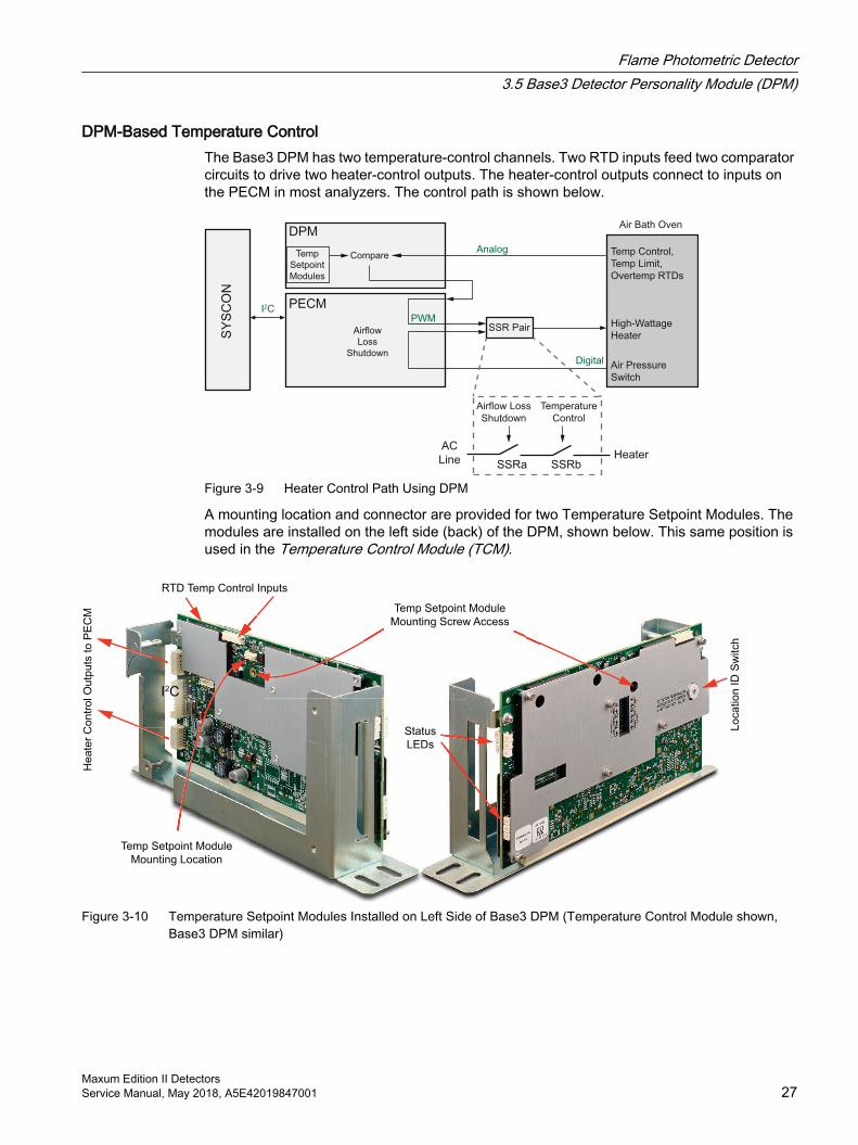
DPM-Based Temperature ControlThe Base3 DPM has two temperature-control channels. Two RTD inputs feed two comparator circuits to drive two heater-control outputs. The heater-control outputs connect to inputs on the PECM in most analyzers. The control path is shown below.
SY
SC
ON
DPM
SSRbSSRa
AC
Line Heater
Airflow Loss
Shutdown
Temperature
Control
I2CPWM
Temp
Setpoint
Modules
Temp Control,
Temp Limit,
Overtemp RTDs
Digital Air Pressure
Switch
SSR Pair
Analog
High-Wattage
Heater
Air Bath Oven
PECM
Airflow
Loss
Shutdown
Compare
Figure 3-9 Heater Control Path Using DPM
A mounting location and connector are provided for two Temperature Setpoint Modules. The modules are installed on the left side (back) of the DPM, shown below. This same position is used in the Temperature Control Module (TCM).
RTD Temp Control Inputs
I2C
He
ate
r C
on
tro
l O
utp
uts
to
PE
CM
Lo
ca
tio
n ID
Sw
itch
Temp Setpoint Module
Mounting Screw Access
Temp Setpoint Module
Mounting Location
Status
LEDs
Figure 3-10 Temperature Setpoint Modules Installed on Left Side of Base3 DPM (Temperature Control Module shown, Base3 DPM similar)
Flame Photometric Detector3.5 Base3 Detector Personality Module (DPM)
Maxum Edition II DetectorsService Manual, May 2018, A5E42019847001 27
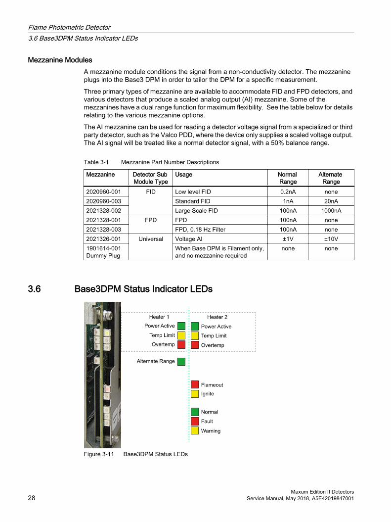
Mezzanine ModulesA mezzanine module conditions the signal from a non-conductivity detector. The mezzanine plugs into the Base3 DPM in order to tailor the DPM for a specific measurement.
Three primary types of mezzanine are available to accommodate FID and FPD detectors, and various detectors that produce a scaled analog output (AI) mezzanine. Some of the mezzanines have a dual range function for maximum flexibility. See the table below for details relating to the various mezzanine options.
The AI mezzanine can be used for reading a detector voltage signal from a specialized or third party detector, such as the Valco PDD, where the device only supplies a scaled voltage output. The AI signal will be treated like a normal detector signal, with a 50% balance range.
Table 3-1 Mezzanine Part Number Descriptions
Mezzanine Detector Sub Module Type
Usage Normal Range
Alternate Range
2020960-001 FID Low level FID 0.2nA none2020960-003 Standard FID 1nA 20nA2021328-002 Large Scale FID 100nA 1000nA2021328-001 FPD FPD 100nA none2021328-003 FPD, 0.18 Hz Filter 100nA none2021326-001 Universal Voltage AI ±1V ±10V1901614-001 Dummy Plug
When Base DPM is Filament only, and no mezzanine required
none none
3.6 Base3DPM Status Indicator LEDs
Normal
Fault
Warning
Power Active
Heater 2
Temp Limit
Overtemp
Flameout
Ignite
Alternate Range
Power Active
Heater 1
Temp Limit
Overtemp
Figure 3-11 Base3DPM Status LEDs
Flame Photometric Detector3.6 Base3DPM Status Indicator LEDs
Maxum Edition II Detectors28 Service Manual, May 2018, A5E42019847001
3.7 Replacing a Base3DPM
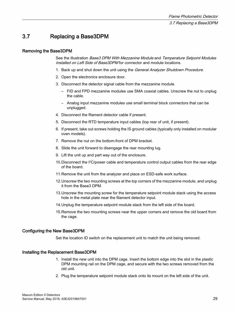
Removing the Base3DPMSee the illustration Base3 DPM With Mezzanine Module and Temperature Setpoint Modules Installed on Left Side of Base3DPM for connector and module locations.
1. Back up and shut down the unit using the General Analyzer Shutdown Procedure.
2. Open the electronics enclosure door.
3. Disconnect the detector signal cable from the mezzanine module.
– FID and FPD mezzanine modules use SMA coaxial cables. Unscrew the nut to unplug the cable.
– Analog input mezzanine modules use small terminal block connectors that can be unplugged.
4. Disconnect the fIlament detector cable if present.
5. Disconnect the RTD temperature input cables (top rear of unit, if present).
6. If present, take out screws holding the IS ground cables (typically only installed on modular oven models).
7. Remove the nut on the bottom-front of DPM bracket.
8. Slide the unit forward to disengage the rear mounting lug.
9. Lift the unit up and part way out of the enclosure.
10.Disconnect the I2C/power cable and temperature control output cables from the rear edge of the board.
11.Remove the unit from the analyzer and place on ESD-safe work surface.
12.Unscrew the two mounting screws at the top corners of the mezzanine module, and unplug it from the Base3 DPM.
13.Unscrew the mounting screw for the temperature setpoint module stack using the access hole in the metal plate near the filament detector input.
14.Unplug the temperature setpoint module stack from the left side of the board.
15.Remove the two mounting screws near the upper corners and remove the old board from the cage.
Configuring the New Base3DPMSet the location ID switch on the replacement unit to match the unit being removed.
Installing the Replacement Base3DPM1. Install the new unit into the DPM cage. Insert the bottom edge into the slot in the plastic
DPM mounting rail on the DPM cage, and secure with the two screws removed from the old unit.
2. Plug the temperature setpoint module stack onto its mount on the left side of the unit.
Flame Photometric Detector3.7 Replacing a Base3DPM
Maxum Edition II DetectorsService Manual, May 2018, A5E42019847001 29
3. Reinstall the screw to secure the temperature setpoint module stack through the access hole on the right side of the unit.
4. Plug the mezzanine module onto its connector on the right side of the unit, and reinstall the two screws ear the top edge.
5. Insert the rear lug into the slot at the rear of the DPM mounting position with the mounting stud at the front inserted through the slot in the DPM bracket.
6. Slide backward to lock the rear mounting lug into the slot.
7. Reinstall the nut on the threaded stud to secure the DPM.
8. Reconnect the I2C/power cable and temperature control output cables from the rear edge of the board.
9. Reconnect the RTD temperature input cables (top rear of unit, if present).
10.Reconnect the fIlament detector cable if present.
11.Reconnect the detector signal cable from the mezzanine module.
12.Follow the steps in the General Analyzer Startup Procedure.
3.8 FPD Specifications
Table 3-2 Flame Photometric Detector (FPD)
Parameter ValueTarget Components SulfurMeasurement Type MassSmallest Measuring Range (at 60°C oven temperature) 0 to 1 ppm ±5%Typical Measuring Range (at 60°C oven temperature) 0 to 10 ppm ±3% FS
up to 0 to 500 ppm ±2% FS
Dynamic Range 102
Linear Range 70 (70:1) linearizedSelectivity 104 to 1
Sulfur to CarbonTemperature Range 105 to 150°CIgnition type Glow PlugElectrical Data 2V at 3A (Maximum, only for flame ignition)
Flame Photometric Detector3.8 FPD Specifications
Maxum Edition II Detectors30 Service Manual, May 2018, A5E42019847001
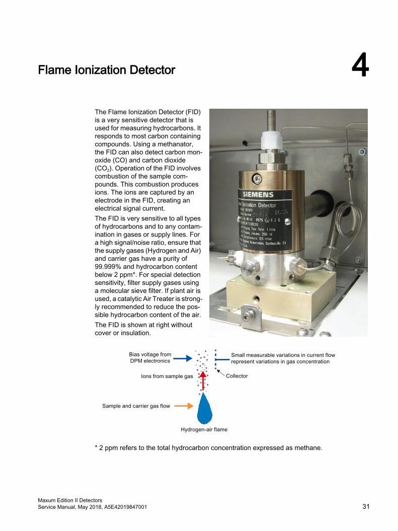
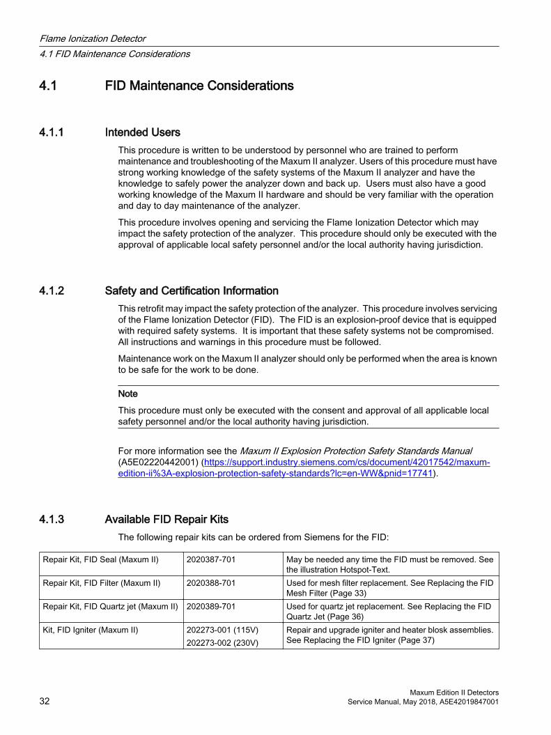
Flame Ionization Detector 4The Flame Ionization Detector (FID) is a very sensitive detector that is used for measuring hydrocarbons. It responds to most carbon containing compounds. Using a methanator, the FID can also detect carbon mon‐oxide (CO) and carbon dioxide (CO2). Operation of the FID involves combustion of the sample com‐pounds. This combustion produces ions. The ions are captured by an electrode in the FID, creating an electrical signal current.The FID is very sensitive to all types of hydrocarbons and to any contam‐ination in gases or supply lines. For a high signal/noise ratio, ensure that the supply gases (Hydrogen and Air) and carrier gas have a purity of 99.999% and hydrocarbon content below 2 ppm*. For special detection sensitivity, filter supply gases using a molecular sieve filter. If plant air is used, a catalytic Air Treater is strong‐ly recommended to reduce the pos‐sible hydrocarbon content of the air.The FID is shown at right without cover or insulation.
* 2 ppm refers to the total hydrocarbon concentration expressed as methane.
Maxum Edition II DetectorsService Manual, May 2018, A5E42019847001 31
4.1 FID Maintenance Considerations
4.1.1 Intended UsersThis procedure is written to be understood by personnel who are trained to perform maintenance and troubleshooting of the Maxum II analyzer. Users of this procedure must have strong working knowledge of the safety systems of the Maxum II analyzer and have the knowledge to safely power the analyzer down and back up. Users must also have a good working knowledge of the Maxum II hardware and should be very familiar with the operation and day to day maintenance of the analyzer.
This procedure involves opening and servicing the Flame Ionization Detector which may impact the safety protection of the analyzer. This procedure should only be executed with the approval of applicable local safety personnel and/or the local authority having jurisdiction.
4.1.2 Safety and Certification InformationThis retrofit may impact the safety protection of the analyzer. This procedure involves servicing of the Flame Ionization Detector (FID). The FID is an explosion-proof device that is equipped with required safety systems. It is important that these safety systems not be compromised. All instructions and warnings in this procedure must be followed.
Maintenance work on the Maxum II analyzer should only be performed when the area is known to be safe for the work to be done.
Note
This procedure must only be executed with the consent and approval of all applicable local safety personnel and/or the local authority having jurisdiction.
For more information see the Maxum II Explosion Protection Safety Standards Manual (A5E02220442001) (https://support.industry.siemens.com/cs/document/42017542/maxum-edition-ii%3A-explosion-protection-safety-standards?lc=en-WW&pnid=17741).
4.1.3 Available FID Repair KitsThe following repair kits can be ordered from Siemens for the FID:
Repair Kit, FID Seal (Maxum II) 2020387-701 May be needed any time the FID must be removed. See the illustration Hotspot-Text.
Repair Kit, FID Filter (Maxum II) 2020388-701 Used for mesh filter replacement. See Replacing the FID Mesh Filter (Page 33)
Repair Kit, FID Quartz jet (Maxum II) 2020389-701 Used for quartz jet replacement. See Replacing the FID Quartz Jet (Page 36)
Kit, FID Igniter (Maxum II) 202273-001 (115V)202273-002 (230V)
Repair and upgrade igniter and heater blosk assemblies. See Replacing the FID Igniter (Page 37)
Flame Ionization Detector4.1 FID Maintenance Considerations
Maxum Edition II Detectors32 Service Manual, May 2018, A5E42019847001
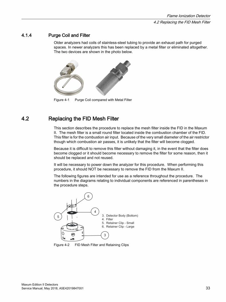
4.1.4 Purge Coil and FilterOlder analyzers had coils of stainless-steel tubing to provide an exhaust path for purged spaces. In newer analyzers this has been replaced by a metal filter or eliminated altogether. The two devices are shown in the photo below.
Figure 4-1 Purge Coil compared with Metal Filter
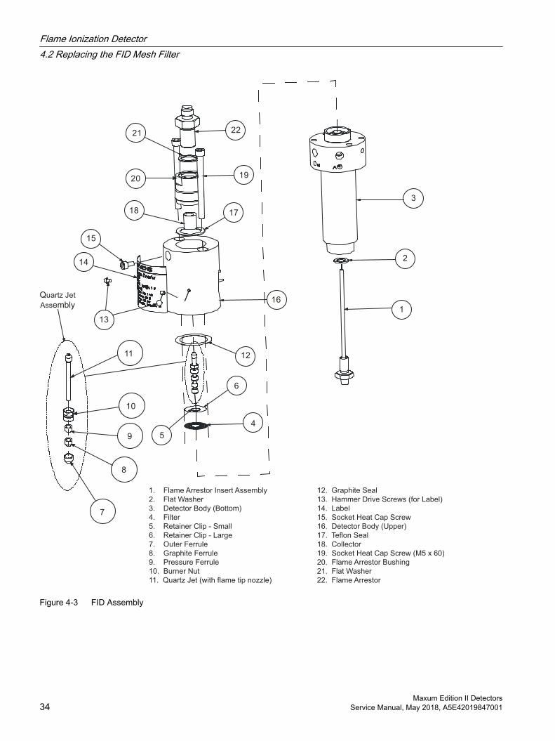
4.2 Replacing the FID Mesh FilterThis section describes the procedure to replace the mesh filter inside the FID in the Maxum II. The mesh filter is a small round filter located inside the combustion chamber of the FID. This filter is for the combustion air input. Because of the very small diameter of the air restrictor though which combustion air passes, it is unlikely that the filter will become clogged.
Because it is difficult to remove this filter without damaging it, in the event that the filter does become clogged or it should become necessary to remove the filter for some reason, then it should be replaced and not reused.
It will be necessary to power down the analyzer for this procedure. When performing this procedure, it should NOT be necessary to remove the FID from the Maxum II.
The following figures are intended for use as a reference throughout the procedure. The numbers in the diagrams relating to individual components are referenced in parentheses in the procedure steps.
3
4
5
6
3. Detector Body (Bottom)
4. Filter
5. Retainer Clip - Small
6. Retainer Clip - Large
Figure 4-2 FID Mesh Filter and Retaining Clips
Flame Ionization Detector4.2 Replacing the FID Mesh Filter
Maxum Edition II DetectorsService Manual, May 2018, A5E42019847001 33
1
2
3
4
5
6
7
8
9
10
11 12
13
14
15
16
1718
1920
21 22
1. Flame Arrestor Insert Assembly 12. Graphite Seal
2. Flat Washer 13. Hammer Drive Screws (for Label)
3. Detector Body (Bottom) 14. Label
4. Filter 15. Socket Heat Cap Screw
5. Retainer Clip - Small 16. Detector Body (Upper)
6. Retainer Clip - Large 17. Teflon Seal
7. Outer Ferrule 18. Collector
8. Graphite Ferrule 19. Socket Heat Cap Screw (M5 x 60)
9. Pressure Ferrule 20. Flame Arrestor Bushing
10. Burner Nut 21. Flat Washer
11. Quartz Jet (with flame tip nozzle) 22. Flame Arrestor
Quartz Jet
Assembly
Figure 4-3 FID Assembly
Flame Ionization Detector4.2 Replacing the FID Mesh Filter
Maxum Edition II Detectors34 Service Manual, May 2018, A5E42019847001
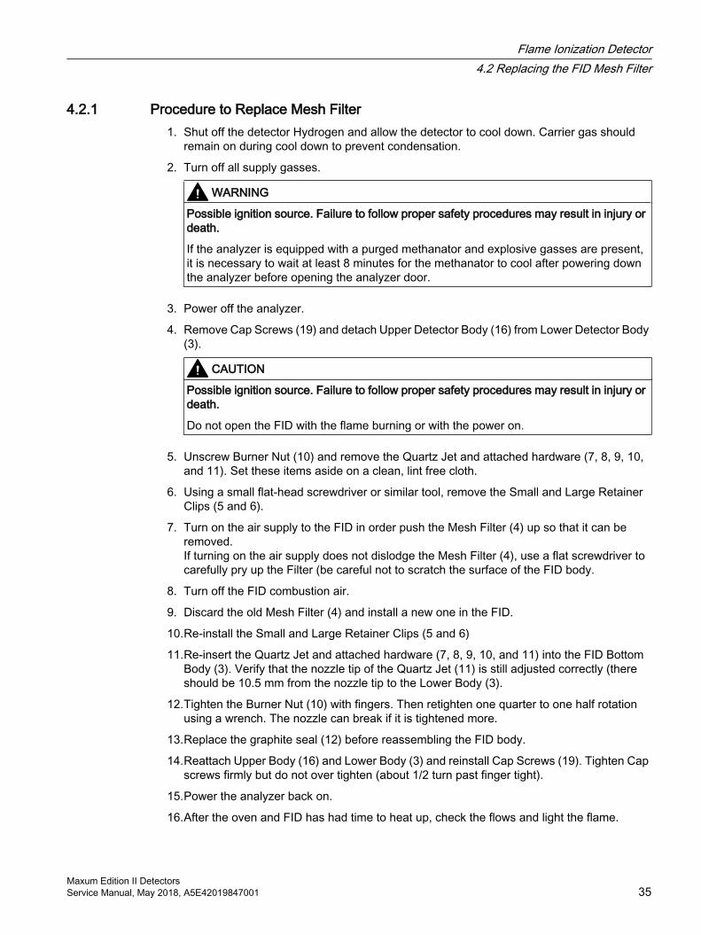
4.2.1 Procedure to Replace Mesh Filter1. Shut off the detector Hydrogen and allow the detector to cool down. Carrier gas should
remain on during cool down to prevent condensation.
2. Turn off all supply gasses.
WARNING
Possible ignition source. Failure to follow proper safety procedures may result in injury or death.
If the analyzer is equipped with a purged methanator and explosive gasses are present, it is necessary to wait at least 8 minutes for the methanator to cool after powering down the analyzer before opening the analyzer door.
3. Power off the analyzer.
4. Remove Cap Screws (19) and detach Upper Detector Body (16) from Lower Detector Body (3).
CAUTION
Possible ignition source. Failure to follow proper safety procedures may result in injury or death.
Do not open the FID with the flame burning or with the power on.
5. Unscrew Burner Nut (10) and remove the Quartz Jet and attached hardware (7, 8, 9, 10, and 11). Set these items aside on a clean, lint free cloth.
6. Using a small flat-head screwdriver or similar tool, remove the Small and Large Retainer Clips (5 and 6).
7. Turn on the air supply to the FID in order push the Mesh Filter (4) up so that it can be removed. If turning on the air supply does not dislodge the Mesh Filter (4), use a flat screwdriver to carefully pry up the Filter (be careful not to scratch the surface of the FID body.
8. Turn off the FID combustion air.
9. Discard the old Mesh Filter (4) and install a new one in the FID.
10.Re-install the Small and Large Retainer Clips (5 and 6)
11.Re-insert the Quartz Jet and attached hardware (7, 8, 9, 10, and 11) into the FID Bottom Body (3). Verify that the nozzle tip of the Quartz Jet (11) is still adjusted correctly (there should be 10.5 mm from the nozzle tip to the Lower Body (3).
12.Tighten the Burner Nut (10) with fingers. Then retighten one quarter to one half rotation using a wrench. The nozzle can break if it is tightened more.
13.Replace the graphite seal (12) before reassembling the FID body.
14.Reattach Upper Body (16) and Lower Body (3) and reinstall Cap Screws (19). Tighten Cap screws firmly but do not over tighten (about 1/2 turn past finger tight).
15.Power the analyzer back on.
16.After the oven and FID has had time to heat up, check the flows and light the flame.
Flame Ionization Detector4.2 Replacing the FID Mesh Filter
Maxum Edition II DetectorsService Manual, May 2018, A5E42019847001 35
4.3 Replacing the FID Quartz JetThis section describes the procedure to replace the Quartz Jet inside the FID in the Maxum II. The Quartz Jet is a thin quartz tube that includes the burner nozzle tip for the FID flame. This item rarely needs replaced.
It will be necessary to power down the analyzer for this procedure. When performing this procedure, it should NOT be necessary to remove the FID from the Maxum II.
4.3.1 Procedure to Replace Quartz Jet1. Shut off the detector Hydrogen and allow the detector to cool down. Carrier gas should
remain on during cool down to prevent condensation.
2. Turn off all supply gasses.
WARNING
Possible ignition source. Failure to follow proper safety procedures may result in injury or death.
If the analyzer is equipped with a purged methanator and explosive gasses are present, it is necessary to wait at least 8 minutes for the methanator to cool after powering down the analyzer before opening the analyzer door.
3. Power off the analyzer.
4. Remove Cap Screws (19) and detach Upper Detector Body (16) from Lower Detector Body (3).
5. Unscrew the Burner Nut (10) and remove the Quartz Jet and attached hardware (7, 8, 9, 10, and 11).
6. Detach the Quartz Jet (11) from the Ferrules (7, 8, 9) and the Burner Nut (10). Make note of the way they are assembled.
7. If Quartz Jet (11) is dirty or clogged, it may be possible to clean it using solvent in an ultrasonic cleaner. However, replacement is recommended. If attempting to clean the quartz jet, allow any excess solvent to evaporate before reinstalling.
8. Assemble the replacement (or cleaned) Quartz Jet (11) and associated hardware (7, 8, 9, and 10).
9. Reinsert the Quartz Jet (and other hardware) into the Lower Detector Body (3). Before tightening the Burner Nut (10), adjust the nozzle (flame tip). The distance from nozzle tip to the Lower Body (3) should be 10.5 mm. Tighten the Burner Nut (10) with fingers. Then retighten one quarter to one half rotation using a wrench. The nozzle can break if it is tightened more.
10.Replace graphite seal (12) between the Upper Detector Body (16) and Lower Detector Body (3) before reassembling the FID body.
11.Reattach Upper Body (16) and Lower Body (3) and reinstall Cap Screws (19). Tighten Cap screws firmly but do not over tighten (about 1/2 turn past finger tight).
Flame Ionization Detector4.3 Replacing the FID Quartz Jet
Maxum Edition II Detectors36 Service Manual, May 2018, A5E42019847001
12.Power the analyzer back on.
13.After the oven and FID has had time to heat up, check the flows and light the flame.
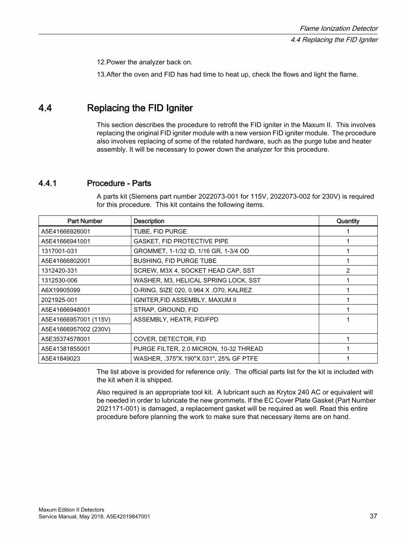
4.4 Replacing the FID IgniterThis section describes the procedure to retrofit the FID igniter in the Maxum II. This involves replacing the original FID igniter module with a new version FID igniter module. The procedure also involves replacing of some of the related hardware, such as the purge tube and heater assembly. It will be necessary to power down the analyzer for this procedure.
4.4.1 Procedure - PartsA parts kit (Siemens part number 2022073-001 for 115V, 2022073-002 for 230V) is required for this procedure. This kit contains the following items.
Part Number Description QuantityA5E41666926001 TUBE, FID PURGE 1A5E41666941001 GASKET, FID PROTECTIVE PIPE 11317001-031 GROMMET, 1-1/32 ID, 1/16 GR, 1-3/4 OD 1A5E41666802001 BUSHING, FID PURGE TUBE 11312420-331 SCREW, M3X 4, SOCKET HEAD CAP, SST 21312530-006 WASHER, M3, HELICAL SPRING LOCK, SST 1A6X19905099 O-RING, SIZE 020, 0.964 X .O70, KALREZ 12021925-001 IGNITER,FID ASSEMBLY, MAXUM II 1A5E41666948001 STRAP, GROUND, FID 1A5E41666957001 (115V) ASSEMBLY, HEATR, FID/FPD 1A5E41666957002 (230V)A5E35374578001 COVER, DETECTOR, FID 1A5E41381855001 PURGE FILTER, 2.0 MICRON, 10-32 THREAD 1A5E41849023 WASHER, .375"X.190"X.031", 25% GF PTFE 1
The list above is provided for reference only. The official parts list for the kit is included with the kit when it is shipped.
Also required is an appropriate tool kit. A lubricant such as Krytox 240 AC or equivalent will be needed in order to lubricate the new grommets. If the EC Cover Plate Gasket (Part Number 2021171-001) is damaged, a replacement gasket will be required as well. Read this entire procedure before planning the work to make sure that necessary items are on hand.
Flame Ionization Detector4.4 Replacing the FID Igniter
Maxum Edition II DetectorsService Manual, May 2018, A5E42019847001 37
4.4.2 Procedure - Removing the Detector
Note
All figures are located at the end of this procedure.
1. From GCP, create a database backup of the Maxum analyzer that is to be modified (See the Gas Chromatograph Portal User Manual for instructions).
2. From GCP, verify operation of analyzer. Verify that there are no alarms or that all alarms are accounted for. (See the Gas Chromatograph Portal User Manual for instructions).
3. Verify that all parts of the new FID igniter kit are on site prior to starting. Contents of the kit are listed in the inventory list that is shipped with the kit.
4. Extinguish the flame to the FID either by shutting off the air supply to the detector (for hydrogen carrier) or shutting off the hydrogen to the detector (if not using hydrogen carrier). In order to prevent condensation in the detector, allow carrier to flow for several minutes after flame is extinguished. Use a mirror to check for condensation at the FID vent to verify the flame is not lit (no condensation means the flame is not lit).
WARNING
Possible ignition source. Failure to follow proper safety procedures may result in injury or death.
If the analyzer is equipped with a purged methanator and explosive gasses are present, it is necessary to wait at least 8 minutes for the methanator to cool after powering down the analyzer before opening the analyzer door.
5. Power down the analyzer.
Flame Ionization Detector4.4 Replacing the FID Igniter
Maxum Edition II Detectors38 Service Manual, May 2018, A5E42019847001
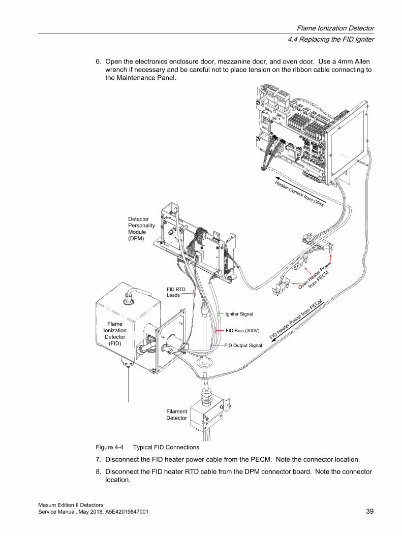
6. Open the electronics enclosure door, mezzanine door, and oven door. Use a 4mm Allen wrench if necessary and be careful not to place tension on the ribbon cable connecting to the Maintenance Panel.
FID Output Signal
FID Bias (300V)
Igniter Signal
FID RTD
Leads
Ove
n Heate
r Power
from
PECM
Filament
Detector
Flame
Ionization
Detector
(FID)
Detector
Personality
Module
(DPM)
Heater Control from DPM
FID H
eater P
ower fro
m P
ECM
Figure 4-4 Typical FID Connections
7. Disconnect the FID heater power cable from the PECM. Note the connector location.
8. Disconnect the FID heater RTD cable from the DPM connector board. Note the connector location.
Flame Ionization Detector4.4 Replacing the FID Igniter
Maxum Edition II DetectorsService Manual, May 2018, A5E42019847001 39
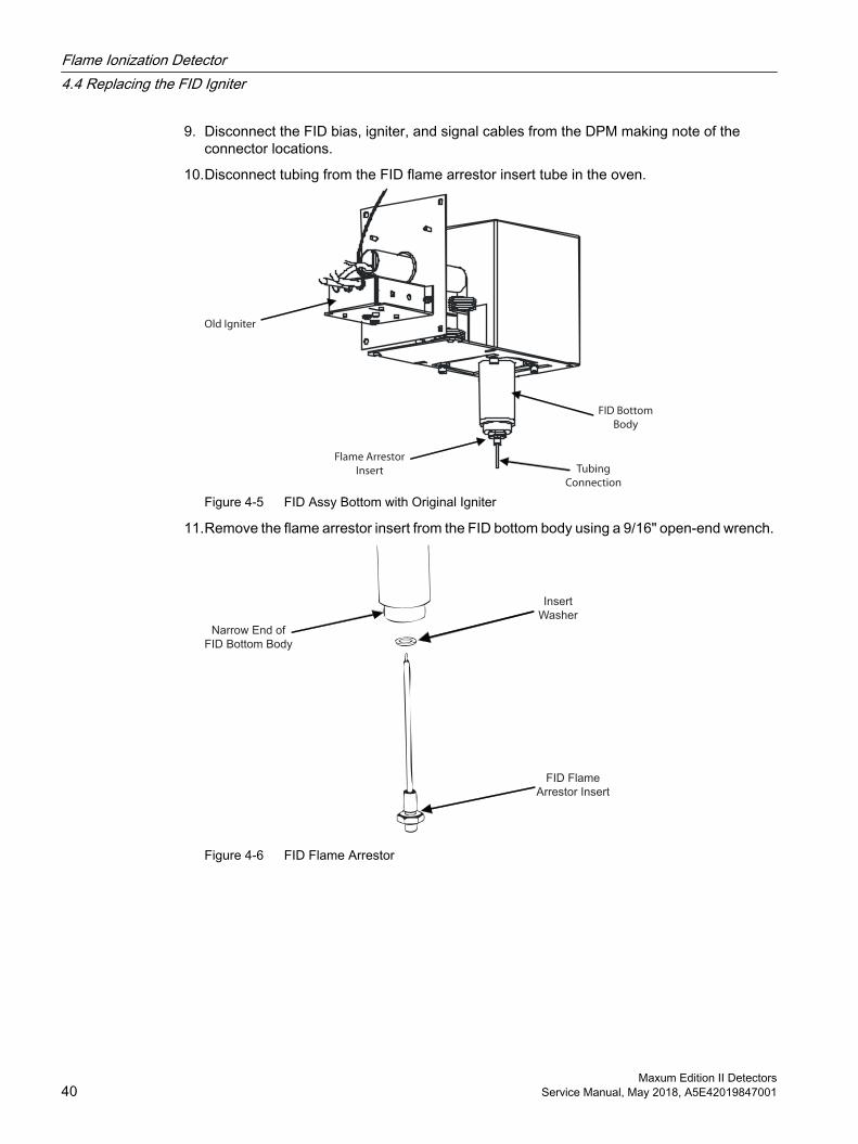
9. Disconnect the FID bias, igniter, and signal cables from the DPM making note of the connector locations.
10.Disconnect tubing from the FID flame arrestor insert tube in the oven.
Flame Arrestor
Insert
Old Igniter
Tubing
Connection
FID Bottom
Body
Figure 4-5 FID Assy Bottom with Original Igniter
11.Remove the flame arrestor insert from the FID bottom body using a 9/16" open-end wrench.
FID Flame
Arrestor Insert
Narrow End of
FID Bottom Body
Insert
Washer
Figure 4-6 FID Flame Arrestor
Flame Ionization Detector4.4 Replacing the FID Igniter
Maxum Edition II Detectors40 Service Manual, May 2018, A5E42019847001
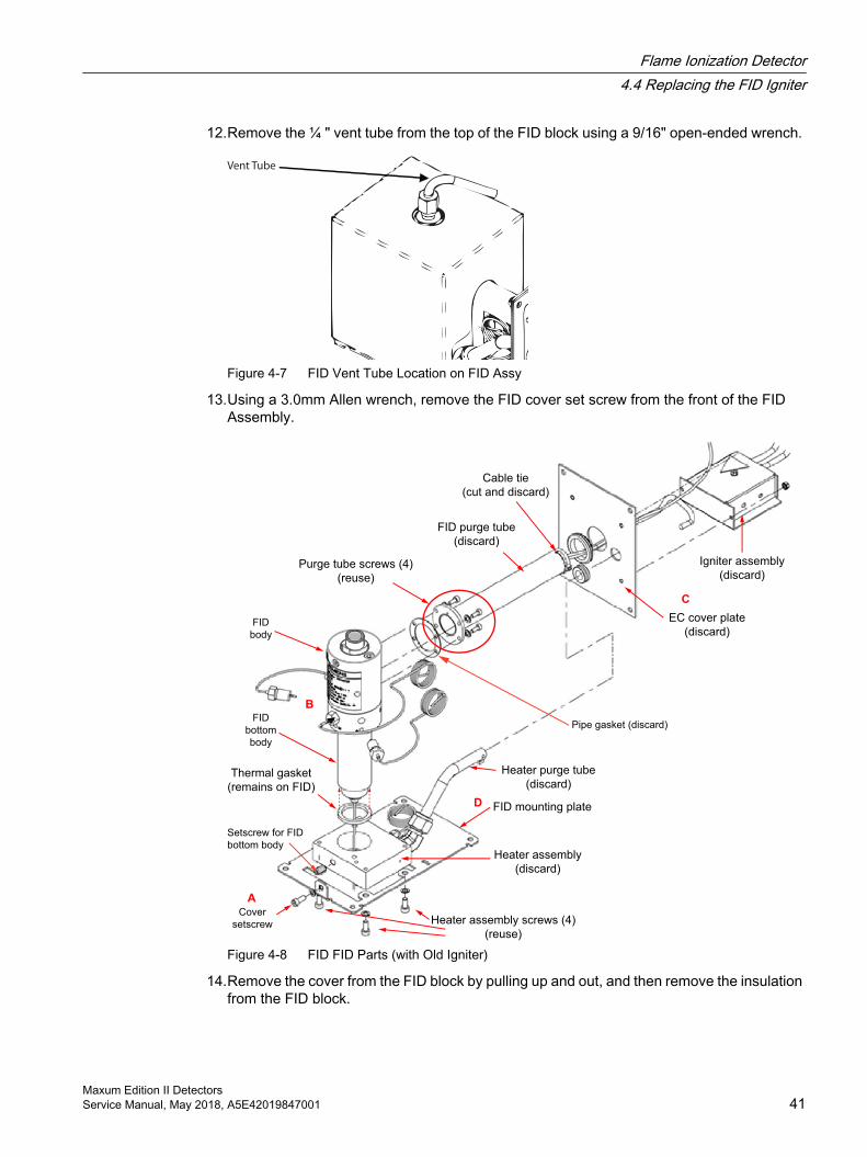
12.Remove the ¼ " vent tube from the top of the FID block using a 9/16" open-ended wrench.
Vent Tube
Figure 4-7 FID Vent Tube Location on FID Assy
13.Using a 3.0mm Allen wrench, remove the FID cover set screw from the front of the FID Assembly.
FID purge tube
(discard)
Purge tube screws (4)
(reuse)
EC cover plate
(discard)
Heater assembly
(discard)
Igniter assembly
(discard)
FID mounting plate
Heater assembly screws (4)
(reuse)
Thermal gasket
(remains on FID)
Setscrew for FID
bottom body
FID
bottom
body
FID
body
Heater purge tube
(discard)
Cable tie
(cut and discard)
Pipe gasket (discard)
Cover
setscrew
A
D
B
C
Figure 4-8 FID FID Parts (with Old Igniter)
14.Remove the cover from the FID block by pulling up and out, and then remove the insulation from the FID block.
Flame Ionization Detector4.4 Replacing the FID Igniter
Maxum Edition II DetectorsService Manual, May 2018, A5E42019847001 41
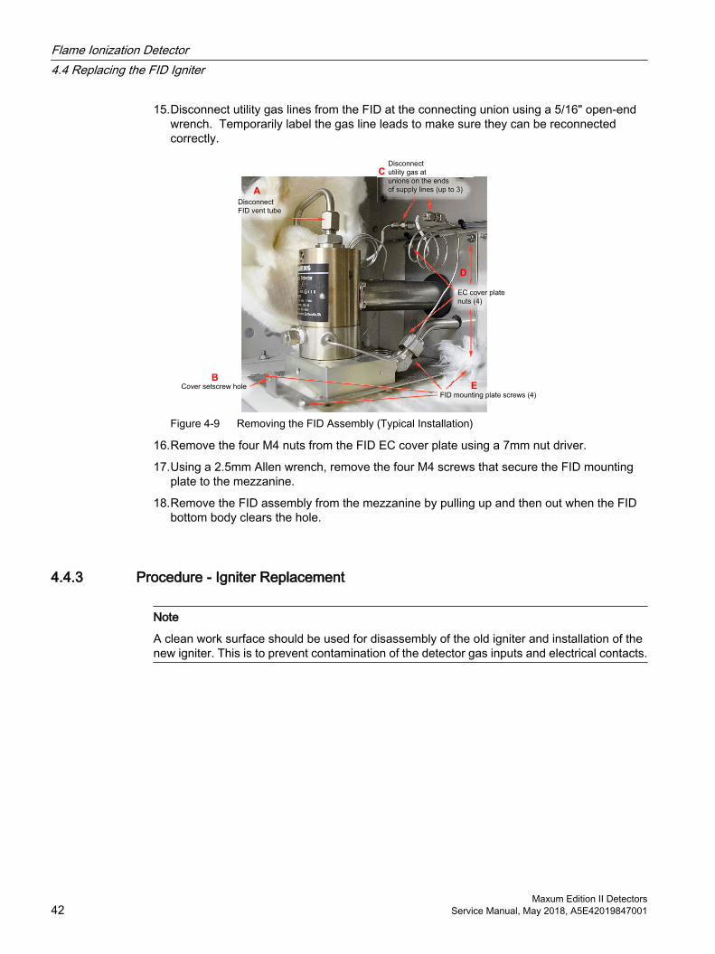
15.Disconnect utility gas lines from the FID at the connecting union using a 5/16" open-end wrench. Temporarily label the gas line leads to make sure they can be reconnected correctly.
Disconnect
utility gas at
unions on the ends
of supply lines (up to 3)
Cover setscrew hole
Disconnect
FID vent tube
EC cover plate
nuts (4)
A
B
D
C
FID mounting plate screws (4)
E
Figure 4-9 Removing the FID Assembly (Typical Installation)
16.Remove the four M4 nuts from the FID EC cover plate using a 7mm nut driver.
17.Using a 2.5mm Allen wrench, remove the four M4 screws that secure the FID mounting plate to the mezzanine.
18.Remove the FID assembly from the mezzanine by pulling up and then out when the FID bottom body clears the hole.
4.4.3 Procedure - Igniter Replacement
Note
A clean work surface should be used for disassembly of the old igniter and installation of the new igniter. This is to prevent contamination of the detector gas inputs and electrical contacts.
Flame Ionization Detector4.4 Replacing the FID Igniter
Maxum Edition II Detectors42 Service Manual, May 2018, A5E42019847001
Igniter
Mounting/ground strap
FID P
urge Tube
FID purge tube grommet
Utility
gas lines
(Do not disconnect here.
Disconnect at unions on the
ends of supply lines )
Setscrew for FID
bottom body
Setscrew
for FID coverHeater block mounting screws (4)
FID mounting plate
Heater assembly
Heater purge tube
Heater purge tube sealing grommet (Heyco)
(A5E35380226)
Detector bushing (A5E41666802001)
and o-ring (A6X19905099)
Pipe gasket (A5E41666941001)
Set screw for ground strap
Install signal cable so
end is aligned with
igniter cable ends
Insulation
Insulation
Insulation
Detector Bushing
FID
body
FID
cover
EC cover plate
(A5E35374578001)
Thermal gasket
(2021263-001)
Purge filter (A5E41381855001)
and washer (A5E41849023)
Ground strap set screw goes here
Hole for purge filter
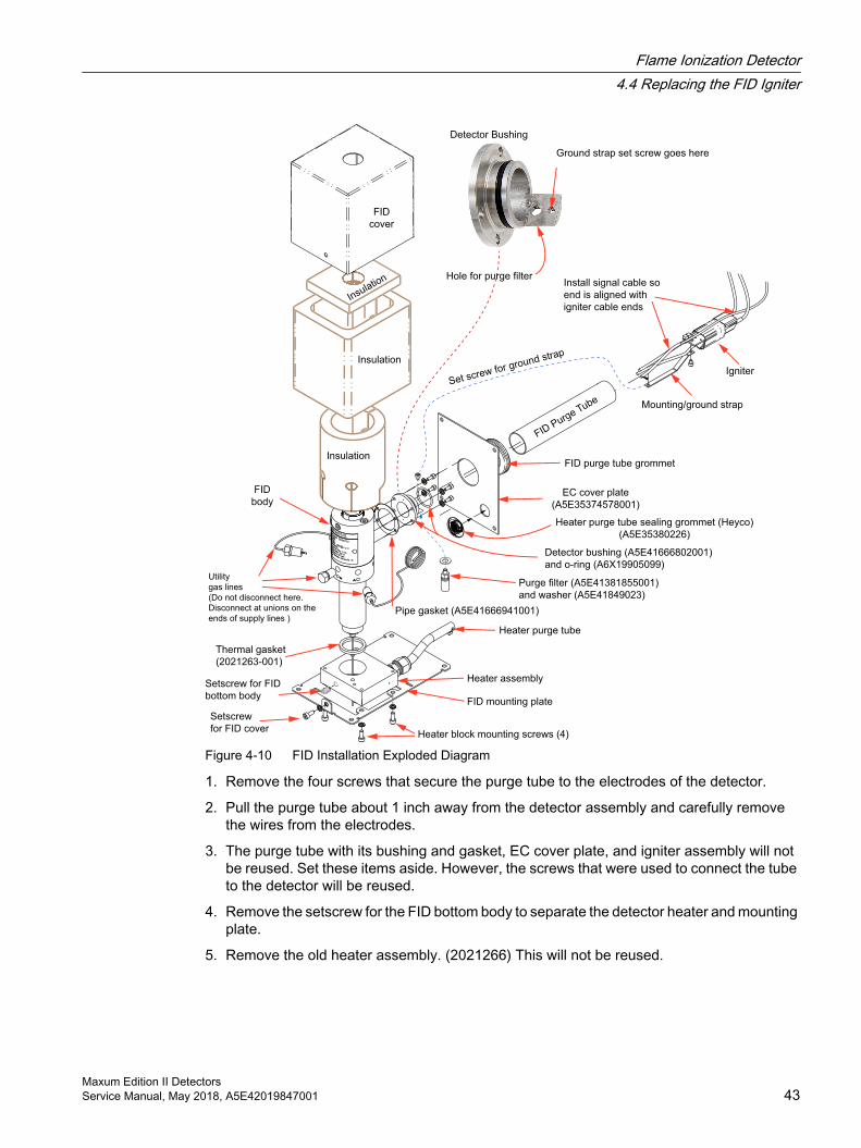
Figure 4-10 FID Installation Exploded Diagram
1. Remove the four screws that secure the purge tube to the electrodes of the detector.
2. Pull the purge tube about 1 inch away from the detector assembly and carefully remove the wires from the electrodes.
3. The purge tube with its bushing and gasket, EC cover plate, and igniter assembly will not be reused. Set these items aside. However, the screws that were used to connect the tube to the detector will be reused.
4. Remove the setscrew for the FID bottom body to separate the detector heater and mounting plate.
5. Remove the old heater assembly. (2021266) This will not be reused.
Flame Ionization Detector4.4 Replacing the FID Igniter
Maxum Edition II DetectorsService Manual, May 2018, A5E42019847001 43
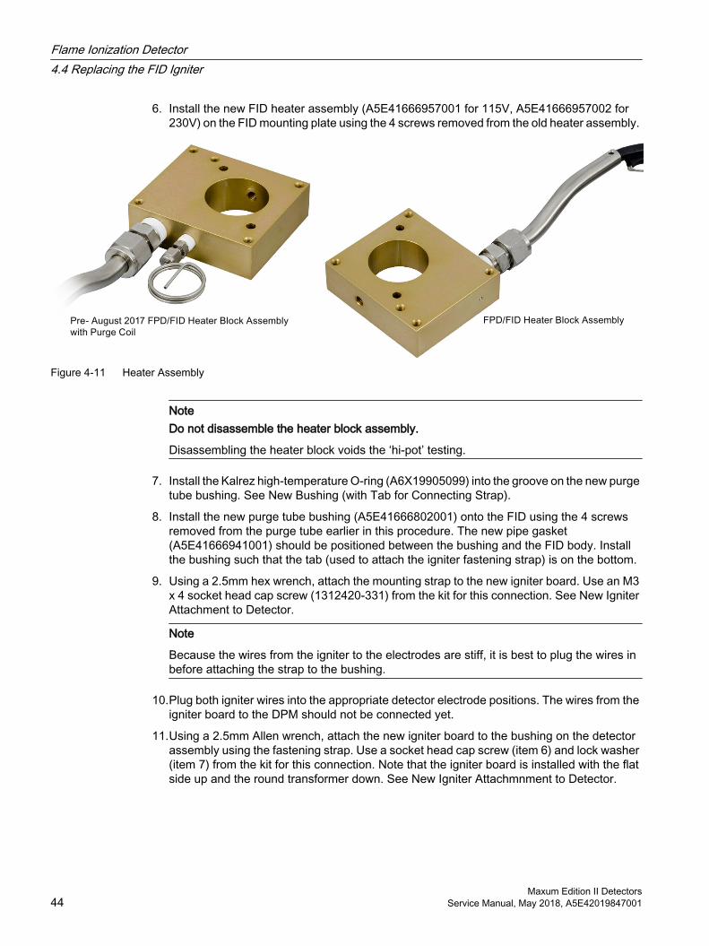
6. Install the new FID heater assembly (A5E41666957001 for 115V, A5E41666957002 for 230V) on the FID mounting plate using the 4 screws removed from the old heater assembly.
Figure 4-11 Heater Assembly
NoteDo not disassemble the heater block assembly.
Disassembling the heater block voids the ‘hi-pot’ testing.
7. Install the Kalrez high-temperature O-ring (A6X19905099) into the groove on the new purge tube bushing. See New Bushing (with Tab for Connecting Strap).
8. Install the new purge tube bushing (A5E41666802001) onto the FID using the 4 screws removed from the purge tube earlier in this procedure. The new pipe gasket (A5E41666941001) should be positioned between the bushing and the FID body. Install the bushing such that the tab (used to attach the igniter fastening strap) is on the bottom.
9. Using a 2.5mm hex wrench, attach the mounting strap to the new igniter board. Use an M3 x 4 socket head cap screw (1312420-331) from the kit for this connection. See New Igniter Attachment to Detector.
Note
Because the wires from the igniter to the electrodes are stiff, it is best to plug the wires in before attaching the strap to the bushing.
10.Plug both igniter wires into the appropriate detector electrode positions. The wires from the igniter board to the DPM should not be connected yet.
11.Using a 2.5mm Allen wrench, attach the new igniter board to the bushing on the detector assembly using the fastening strap. Use a socket head cap screw (item 6) and lock washer (item 7) from the kit for this connection. Note that the igniter board is installed with the flat side up and the round transformer down. See New Igniter Attachmnment to Detector.
Flame Ionization Detector4.4 Replacing the FID Igniter
Maxum Edition II Detectors44 Service Manual, May 2018, A5E42019847001
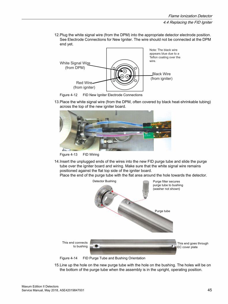
12.Plug the white signal wire (from the DPM) into the appropriate detector electrode position. See Electrode Connections for New Igniter. The wire should not be connected at the DPM end yet.
White Signal Wire
(from DPM)
Black Wire
(from igniter)Red Wire
(from igniter)
Note: The black wire
appears blue due to a
Teflon coating over the
wire.
Figure 4-12 FID New Igniter Electrode Connections
13.Place the white signal wire (from the DPM, often covered by black heat-shrinkable tubing) across the top of the new igniter board.
Figure 4-13 FID Wiring
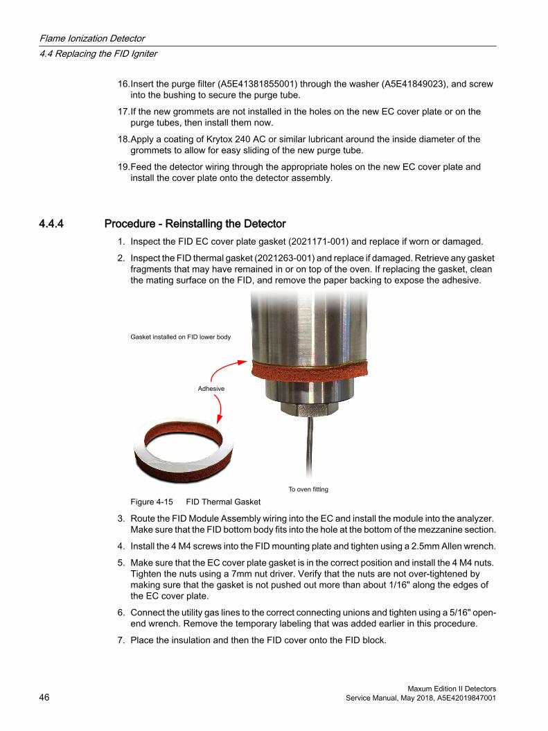
14.Insert the unplugged ends of the wires into the new FID purge tube and slide the purge tube over the igniter board and wiring. Make sure that the white signal wire remains positioned against the flat top side of the igniter board. Place the end of the purge tube with the flat area around the hole towards the detector.
Detector Bushing
Figure 4-14 FID Purge Tube and Bushing Orientation
15.Line up the hole on the new purge tube with the hole on the bushing. The holes will be on the bottom of the purge tube when the assembly is in the upright, operating position.
Flame Ionization Detector4.4 Replacing the FID Igniter
Maxum Edition II DetectorsService Manual, May 2018, A5E42019847001 45
16.Insert the purge filter (A5E41381855001) through the washer (A5E41849023), and screw into the bushing to secure the purge tube.
17.If the new grommets are not installed in the holes on the new EC cover plate or on the purge tubes, then install them now.
18.Apply a coating of Krytox 240 AC or similar lubricant around the inside diameter of the grommets to allow for easy sliding of the new purge tube.
19.Feed the detector wiring through the appropriate holes on the new EC cover plate and install the cover plate onto the detector assembly.
4.4.4 Procedure - Reinstalling the Detector1. Inspect the FID EC cover plate gasket (2021171-001) and replace if worn or damaged.
2. Inspect the FID thermal gasket (2021263-001) and replace if damaged. Retrieve any gasket fragments that may have remained in or on top of the oven. If replacing the gasket, clean the mating surface on the FID, and remove the paper backing to expose the adhesive.
Gasket installed on FID lower body
To oven fitting
Adhesive
Figure 4-15 FID Thermal Gasket
3. Route the FID Module Assembly wiring into the EC and install the module into the analyzer. Make sure that the FID bottom body fits into the hole at the bottom of the mezzanine section.
4. Install the 4 M4 screws into the FID mounting plate and tighten using a 2.5mm Allen wrench.
5. Make sure that the EC cover plate gasket is in the correct position and install the 4 M4 nuts. Tighten the nuts using a 7mm nut driver. Verify that the nuts are not over-tightened by making sure that the gasket is not pushed out more than about 1/16" along the edges of the EC cover plate.
6. Connect the utility gas lines to the correct connecting unions and tighten using a 5/16" open-end wrench. Remove the temporary labeling that was added earlier in this procedure.
7. Place the insulation and then the FID cover onto the FID block.
Flame Ionization Detector4.4 Replacing the FID Igniter
Maxum Edition II Detectors46 Service Manual, May 2018, A5E42019847001
8. Install the FID cover set screw and tighten using a 3mm Allen wrench.
Note
The next step is important in order to maintain the explosion proof protection of the FID. The threads of the FID flame arrestor must be clean and lubricant or other substances must NOT be applied to the threads.
9. Place the FID flame arrestor insert and washer into the FID bottom body and tighten using a 9/16" open-end wrench. Make sure the flat washer fits into the recessed cavity at the lower end of the FID bottom body to prevent leaks. See Figures 3-4 and 3-5.
10.Connect the FID flame arrestor insert tubing to the correct connection union in the oven using either a 1/4" or 5/16" open-end wrench depending on the fitting size.
11.Route the bias cable, the igniter cable, and the signal cable through the EC and connect them to the FID DPM board locations from which they were unplugged earlier in this procedure.
12.Route the FID heater RTD cable through the EC and plug it into the DPM location from which it was unplugged earlier in this procedure.
13.Route the FID heater power cable through the EC and plug it into the PECM location from which it was unplugged earlier in this procedure.
14.Route the FID heater ground braid through the EC and connect to the appropriate ground lug from which the old one was disconnected.
15.Turn on utility gases and check for leaks.
16.Turn on power to the analyzer and switch the valves checking all possible flow paths for leaks. Refer to plumbing diagram provided in the custom documentation package for flow paths.
17.Turn up oven air to the normal setting and allow the oven to come to temperature and stabilize.
18.Set all gas flows after the detector is up to its temperature set point.
19.With the new igniter, it will be necessary to start Real Time Chromatograms on the HMI in order to light the FID flame. On the HMI, choose the Maintenance Menu, and then select option 5 (Detectors & Real Time Chroms). Then highlight the appropriate FID and then press "View Chrom".
20.At this time you can ignite the FID using the HMI.
21.After 15 to 30 minutes the analyzer will be ready for operation. Verify that the FID operates correctly and put analyzer back on line.
4.5 FID Specifications
Table 4-1 Flame Ionization Detector (FID)
Parameter ValueTarget Components CarbonMeasurement Type Mass
Flame Ionization Detector4.5 FID Specifications
Maxum Edition II DetectorsService Manual, May 2018, A5E42019847001 47
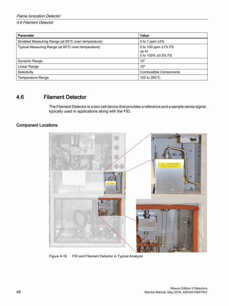
Parameter ValueSmallest Measuring Range (at 60°C oven temperature) 0 to 1 ppm ±3%Typical Measuring Range (at 60°C oven temperature) 0 to 100 ppm ±1% FS
up to 0 to 100% ±0.5% FS
Dynamic Range 107
Linear Range 106
Selectivity Combustible ComponentsTemperature Range 105 to 260°C
4.6 Filament DetectorThe Filament Detector is a two-cell device that provides a reference and a sample sense signal, typically used in applications along with the FID.
Component Locations
Figure 4-16 FID and Filament Detector in Typical Analyzer
Flame Ionization Detector4.6 Filament Detector
Maxum Edition II Detectors48 Service Manual, May 2018, A5E42019847001
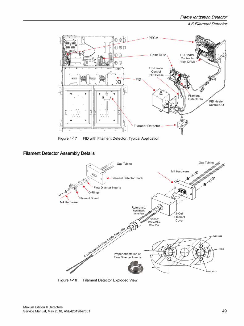
Figure 4-17 FID with Filament Detector, Typical Application
Filament Detector Assembly Details
Figure 4-18 Filament Detector Exploded View
Flame Ionization Detector4.6 Filament Detector
Maxum Edition II DetectorsService Manual, May 2018, A5E42019847001 49
4.6.1 Replacing the Filaments1. Remove the two bolts in the bottom of the detector block.
2. Separate the detector body (bottom) and detector cap (top) to allow access to the filament board.
3. Note location of each wire and disconnect from board. Wires are paired; Sense is White and Blue, and Reference is Red and Black.
4. Remove the screw and both washers holding the board in place.
5. Carefully lift board out of Detector block.
6. Discard the board and O-rings. Do not attempt to reuse old O-rings.
7. Remove the two metal inserts. These CAN be reused.
8. Inspect the metal flow diverter inserts for damage.
9. Before installing new board, examine the mounting surface and the holes for the filaments to verify there is no contamination or scratches on the machined surface. If there is contamination on the surface, clean it using a lint free cloth and a cleaning solvent such as acetone or hexane. If the surface is scratched it may be necessary to replace the complete assembly.
Note
The elements on the board are exposed and are very delicate. Handle the board only by its edges. Hands and tools must be clean.
10.Install the metal inserts in the detector block. These inserts should be installed with the groove perpendicular to the tube holes in the block (so that air cannot flow in a straight path between the holes).
11.Install the new O-rings in hole in the Detector Block. It is also possible to install the O-rings on the filament board instead of in the hole. If installing the O-rings on the board, be careful not to damage the element.
12.Install the Board into the Detector Block. When installing the board, exercise caution not to damage the exposed elements.
13.Reinstall the Flat Washer, Lock Washer, and Button Head Hex Screw. Do not over tighten the screw as this can damage the Board
14.Reconnect wiring to the board. Wiring MUST be connected to the same cells as before. Verify all termination points.
Note
The color coding information for the wiring should be on the Detector Certification Label. Also note that there are two wires of each color. For a specific cell it does not matter which wire is connected to which lead as long as the color is correct.
15.Before installing cover back on the Detector Block, turn on carrier air to verify there are no leaks between the Board and the Block. Turn off carrier after this check is complete.
16.Set the cover in place and reinstall the 4 screws and lockwashers that secure the cover to the detector block.
Flame Ionization Detector4.6 Filament Detector
Maxum Edition II Detectors50 Service Manual, May 2018, A5E42019847001
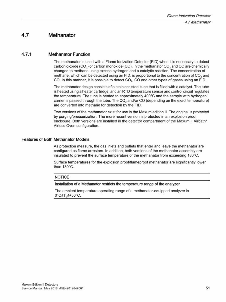
4.7 Methanator
4.7.1 Methanator FunctionThe methanator is used with a Flame Ionization Detector (FID) when it is necessary to detect carbon dioxide (CO2) or carbon monoxide (CO). In the methanator CO2 and CO are chemically changed to methane using excess hydrogen and a catalytic reaction. The concentration of methane, which can be detected using an FID, is proportional to the concentration of CO2 and CO. In this manner, it is possible to detect CO2, CO and other types of gases using an FID.
The methanator design consists of a stainless steel tube that is filled with a catalyst. The tube is heated using a heater cartridge, and an RTD temperature sensor and control circuit regulates the temperature. The tube is heated to approximately 400°C and the sample with hydrogen carrier is passed through the tube. The CO2 and/or CO (depending on the exact temperature) are converted into methane for detection by the FID.
Two versions of the methanator exist for use in the Maxum edition II. The original is protected by purging/pressurization. The more recent version is protected in an explosion proof enclosure. Both versions are installed in the detector compartment of the Maxum II Airbath/Airless Oven configuration.
Features of Both Methanator ModelsAs protection measure, the gas inlets and outlets that enter and leave the methanator are configured as flame arrestors. In addition, both versions of the methanator assembly are insulated to prevent the surface temperature of the methanator from exceeding 180°C.
Surface temperatures for the explosion proof/flameproof methanator are significantly lower than 180°C.
NOTICE
Installation of a Methanator restricts the temperature range of the analyzer
The ambient temperature operating range of a methanator-equipped analyzer is 0°C≤Ta≤+50°C.
Flame Ionization Detector4.7 Methanator
Maxum Edition II DetectorsService Manual, May 2018, A5E42019847001 51
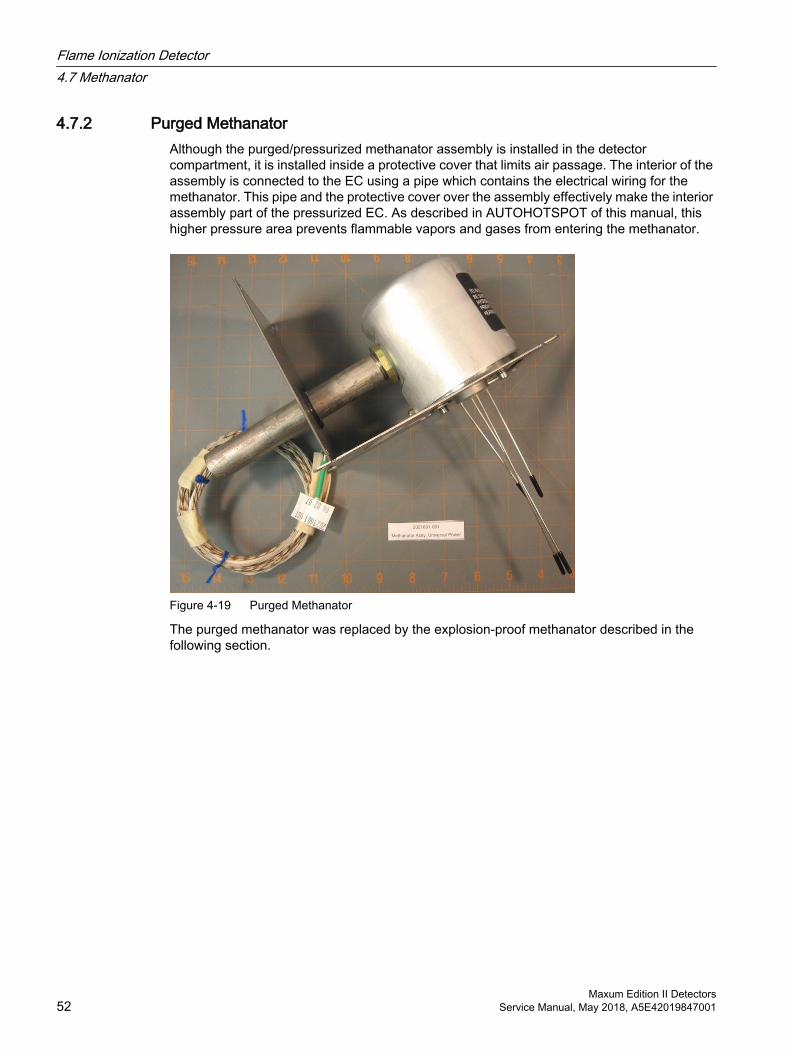
4.7.2 Purged MethanatorAlthough the purged/pressurized methanator assembly is installed in the detector compartment, it is installed inside a protective cover that limits air passage. The interior of the assembly is connected to the EC using a pipe which contains the electrical wiring for the methanator. This pipe and the protective cover over the assembly effectively make the interior assembly part of the pressurized EC. As described in AUTOHOTSPOT of this manual, this higher pressure area prevents flammable vapors and gases from entering the methanator.
Figure 4-19 Purged Methanator
The purged methanator was replaced by the explosion-proof methanator described in the following section.
Flame Ionization Detector4.7 Methanator
Maxum Edition II Detectors52 Service Manual, May 2018, A5E42019847001
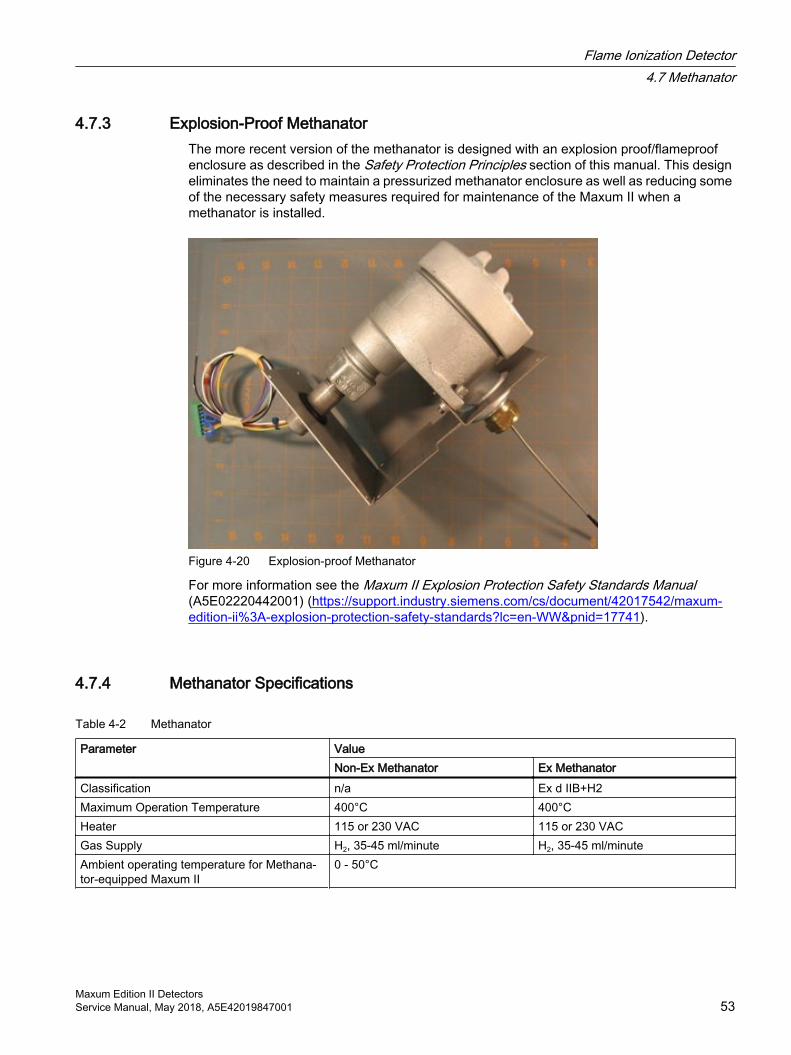
4.7.3 Explosion-Proof MethanatorThe more recent version of the methanator is designed with an explosion proof/flameproof enclosure as described in the Safety Protection Principles section of this manual. This design eliminates the need to maintain a pressurized methanator enclosure as well as reducing some of the necessary safety measures required for maintenance of the Maxum II when a methanator is installed.
Figure 4-20 Explosion-proof Methanator
For more information see the Maxum II Explosion Protection Safety Standards Manual (A5E02220442001) (https://support.industry.siemens.com/cs/document/42017542/maxum-edition-ii%3A-explosion-protection-safety-standards?lc=en-WW&pnid=17741).
4.7.4 Methanator Specifications
Table 4-2 Methanator
Parameter ValueNon-Ex Methanator Ex Methanator
Classification n/a Ex d IIB+H2Maximum Operation Temperature 400°C 400°CHeater 115 or 230 VAC 115 or 230 VACGas Supply H2, 35-45 ml/minute H2, 35-45 ml/minuteAmbient operating temperature for Methana‐tor-equipped Maxum II
0 - 50°C
Flame Ionization Detector4.7 Methanator
Maxum Edition II DetectorsService Manual, May 2018, A5E42019847001 53
4.7.5 Methanator Maintenance Considerations
Purged MethanatorThe methanator should be inspected regularly to ensure there is no physical damage affecting the integrity of the protective cover and to verify that the protective cover is fastened securely in place. The conduit pipe should be attached snugly in accordance with local safety practices. Seals for pipe and cover should fit securely to prevent excessive escape of purge air from around the device.
All gas connections must be made through the tubing that is supplied from the factory and is part of the methanator assembly. This tubing should never be cut or shortened. If there is any physical damage, remove power from the device and replace it.
WARNING
Risk of ignition and explosion
The purged/pressurized methanator must not be operated without purge/pressurization unless it has been verified that the area is free of explosive gases and vapors. This includes opening the door to the EC for routine maintenance.
If the purge air supply of the Maxum II is interrupted during operation, it is imperative that the analyzer be powered down. Once powered down, the electronics-cabinet door must be kept closed for at least 30 minutes. A 30-minute delay is necessary to give the methanator time to cool down sufficiently. If the door to the electronics cabinet is opened prematurely, explosive gas or vapor can ignite by entering the electronics cabinet and then entering the methanator through the conduit tube.
Failure to follow proper safety procedures may result in equipment damage, severe injury, or death.
Explosion Proof MethanatorThe methanator should be inspected regularly to ensure there is no physical damage to the enclosure and to verify the screw-on cap is fully tightened. Secure the setscrew sufficiently to require a tool to open the device.
The conduit pipe screws into a seal at the methanator housing. Up to that point, it is part of the purged space of the EC. The pipe should be attached securely in accordance with local safety practices. The seals for the pipe entry into the EC should fit securely to prevent excessive escape of purge air.
WARNING
Risk of ignition and explosion
The screw-on cap of the explosion proof/flameproof methanator must not be removed unless it has been verified that the area is free of explosive gases and vapors or unless the methanator has been given sufficient time to cool down (at least 30 minutes without power).
Failure to follow proper safety procedures may result in equipment damage, severe injury, or death.
Flame Ionization Detector4.7 Methanator
Maxum Edition II Detectors54 Service Manual, May 2018, A5E42019847001
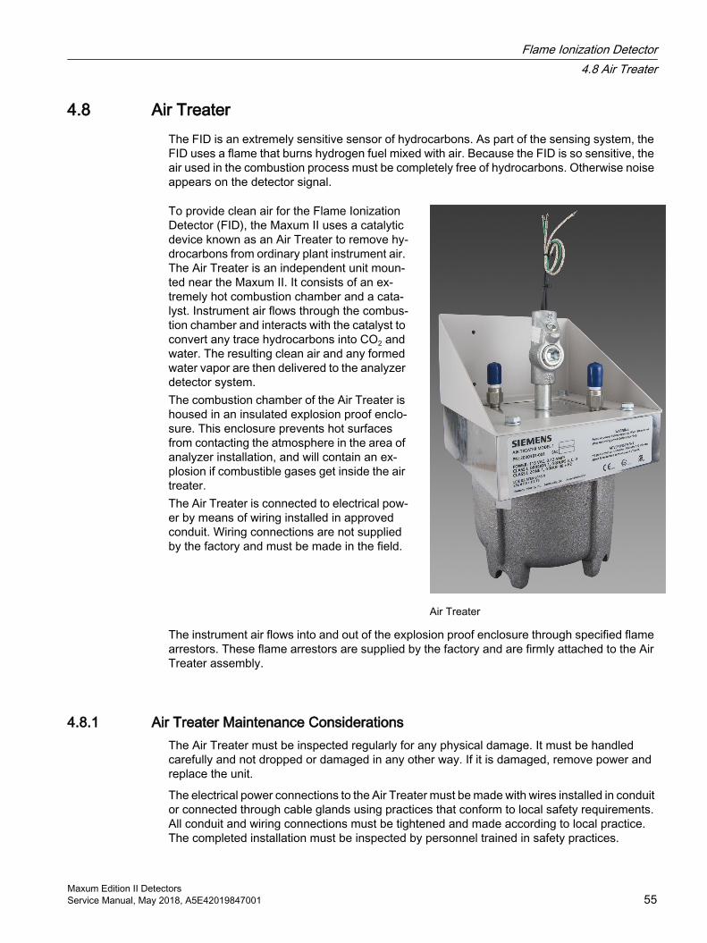
4.8 Air TreaterThe FID is an extremely sensitive sensor of hydrocarbons. As part of the sensing system, the FID uses a flame that burns hydrogen fuel mixed with air. Because the FID is so sensitive, the air used in the combustion process must be completely free of hydrocarbons. Otherwise noise appears on the detector signal.
To provide clean air for the Flame Ionization Detector (FID), the Maxum II uses a catalytic device known as an Air Treater to remove hy‐drocarbons from ordinary plant instrument air. The Air Treater is an independent unit moun‐ted near the Maxum II. It consists of an ex‐tremely hot combustion chamber and a cata‐lyst. Instrument air flows through the combus‐tion chamber and interacts with the catalyst to convert any trace hydrocarbons into CO2 and water. The resulting clean air and any formed water vapor are then delivered to the analyzer detector system.The combustion chamber of the Air Treater is housed in an insulated explosion proof enclo‐sure. This enclosure prevents hot surfaces from contacting the atmosphere in the area of analyzer installation, and will contain an ex‐plosion if combustible gases get inside the air treater.The Air Treater is connected to electrical pow‐er by means of wiring installed in approved conduit. Wiring connections are not supplied by the factory and must be made in the field.
Air Treater
The instrument air flows into and out of the explosion proof enclosure through specified flame arrestors. These flame arrestors are supplied by the factory and are firmly attached to the Air Treater assembly.
4.8.1 Air Treater Maintenance ConsiderationsThe Air Treater must be inspected regularly for any physical damage. It must be handled carefully and not dropped or damaged in any other way. If it is damaged, remove power and replace the unit.
The electrical power connections to the Air Treater must be made with wires installed in conduit or connected through cable glands using practices that conform to local safety requirements. All conduit and wiring connections must be tightened and made according to local practice. The completed installation must be inspected by personnel trained in safety practices.
Flame Ionization Detector4.8 Air Treater
Maxum Edition II DetectorsService Manual, May 2018, A5E42019847001 55
The instrument air connections must always be made through the attached flame arrestors.
The Air Treater must be firmly mounted to the wall, the floor, or a rack on which the analyzer is mounted. Install the Air Treater so that it cannot be damaged during normal maintenance operations.
4.8.2 Air Treater Specifications
Table 4-3 Air Treater
Dimensions Approximately 210 x 210 x 300 mm (81/4" x 81/4" x 113/4") (w x d x h)A minimum of 400 mm (153/4") total clearance is required in depth for removal of the bottom cover
Weight 10.5 kg (23 pounds)Power requirements 115 or 230 VAC, 50 wattsInstallation Panel, rack, or wall mounted near the analyzerConstruction 300 Series Stainless Steel in contact with the treated air. Mounted in an explosion proof aluminum
enclosureInput air quality ● Meet or exceed ISO8573-4 (Class 3) requirements.
● Maximum total hydrocarbon content less than 1 ppm and ● Dew point -20°C (-4°F)
Input air flow ● 250 to 1500 ml/min (depending on requirements)Input pressure 34 to 1034 kPa (5 to 150 psig), depending on flow rate desiredWarm-up time Approximately 90 minutesTreated air purity Up to 95% of the trace hydrocarbons typically found in instrument quality air are removed by the
air treaterCatalyst life Catalyst is not consumed as part of the air treatment so the life is indefinite. However the catalyst
can be poisoned when exposed to sulfur compounds.Safety ● CSA certified for use in Class I, Division 1, Groups B, C, D Hazardous Locations for US and
Canada● ATEX certified for use in Zone 1 or 2, gas group IIB + H2 explosive atmosphere (II 2 G) (Ex d
IIB+H2 T5 Gb)● Temperature Class Rating: T5
Flame Ionization Detector4.8 Air Treater
Maxum Edition II Detectors56 Service Manual, May 2018, A5E42019847001
Valco Pulse Discharge Detector 5The detector can be used in three different versions: HID (helium ionization detector), ECD (electron capture detector) and PID (photo ionization detector). Installation in the Maxum GC is possible without further modification, and the detector can only be used in non-hazardous areas. The PDD uses stable, pulsed DC discharges in helium as the ionization source. The detector's performance data is equal to or better than that of detectors which use radioactive ionization sources. Since a radioactive source is not used, the complex directives for radiation protection need not be observed by the customer.
5.1 PDD SpecificationsFor information on detector gas-supply requirements. see the Maxum II Official Product Specifications (A5E03012338001) (https://support.industry.siemens.com/cs/document/109742522/maxum-ii-official-product-specifications?lc=en-WW&pnid=17741). This publication gives approximate requirements. Specific requirements depend on the application.
Table 5-1 Pulse Discharge Detector, Helium Ionization Mode
Parameter ValueTarget Components AllMeasurement Type MassSmallest Measuring Range (at 60°C oven temperature) 0 to 2 ppm ±5%Typical Measuring Range (at 60°C oven temperature) 0 to 5 ppm ±5% FSDynamic Range 103 at fixed attenuationLinear Range 103 at fixed attenuationSelectivity None without He and NeTemperature Range 70 - 110°C
(higher temperature ranges on request; system configuration dependent)
Table 5-2 Pulse Discharge Detector, Electron Capture Mode
Parameter ValueTarget Components Components with electron affinityMeasurement Type MassSmallest Measuring Range (at 60°C oven temperature) 0 to 2 ppm ±5%Typical Measuring Range (at 60°C oven temperature) 0 to 5 ppm ±5% FSDynamic Range 103 at fixed attenuationLinear Range 103 at fixed attenuation
Maxum Edition II DetectorsService Manual, May 2018, A5E42019847001 57
Parameter ValueSelectivity Components with electron affinity to carbon 103
to 1Temperature Range 70 - 110°C
(higher temperature ranges on request; system configuration dependent)
Table 5-3 Pulse Discharge Detector, Photoionization Mode
Parameter ValueTarget Components Photon sensitive componentsMeasurement Type MassSmallest Measuring Range (at 60°C oven temperature) 0 to 2 ppm ±5%Typical Measuring Range (at 60°C oven temperature) 0 to 5 ppm ±5% FSDynamic Range 103 at fixed attenuationLinear Range 103 at fixed attenuationSelectivity Photon sensitive components
(example: benzene to hexane 103 to 1)Temperature Range 70 - 110°C
(higher temperature ranges on request; system configuration dependent)
Valco Pulse Discharge Detector5.1 PDD Specifications
Maxum Edition II Detectors58 Service Manual, May 2018, A5E42019847001


![0$;80 HGLWLRQ,, 3UR]HVV *DV &KURPDWRJUDSK · • Advance MAXUM edition II Automatic Purge Unit 7KHPD 6HLWH Aufstellungsort 2 MAXUM edition II – Technische Daten 3 MAXUM edition](https://img.pdfslide.us/doc/110x75/5e8286168302c80e5f195a6a/080-hglwlrq-3urhvv-dv-kurpdwrjudsk-a-advance-maxum-edition-ii-automatic.jpg)