Embed Size (px)
Citation preview
MAXON SMARTLINK® CVIntelligent Valve Actuator
Technical Catalog
MAXON SMARTLINK® CV INTELLIGENT VALVE ACTUATOR
0 www.maxoncorp.com 32M-06002E
TABLE OF CONTENTSProduct description .................................................................................................................................. 1
Features and benefits .................................................................................................................................. 1
Applications .................................................................................................................................. 1
Model Number .................................................................................................................................. 2Butterfly valves ........................................................................................................ 2Ball valves ................................................................................................................ 3Control actuator ....................................................................................................... 5Spare actuator ......................................................................................................... 6Control interface ...................................................................................................... 7
Specifications .................................................................................................................................. 8System specifications .............................................................................................. 8Capacities - butterfly valves ..................................................................................... 9Capacities - ball valves ............................................................................................ 11
Materials of construction .................................................................................................................................. 12Butterfly valves ........................................................................................................ 12Ball valves ................................................................................................................ 15
Dimensions and weights .................................................................................................................................. 16Butterfly valves ........................................................................................................ 16Ball valves ................................................................................................................ 23Control interface ...................................................................................................... 30DIN rail assembly ..................................................................................................... 30Interface panel ......................................................................................................... 31
Installation instructions .................................................................................................................................. 32Mechanical installation ............................................................................................ 32Electrical installation ................................................................................................ 32
Operating instructions .................................................................................................................................. 35Control interface ...................................................................................................... 35Wiring checkout ....................................................................................................... 36Operational checkout ............................................................................................... 36User commands ...................................................................................................... 37Valve characterization .............................................................................................. 39MAXON SMARTLINK® commissioning table .......................................................... 40Unit locking and passcode entry .............................................................................. 41Manual operation ..................................................................................................... 42High and low valve position limits ............................................................................ 42Alarm codes ............................................................................................................. 43
Maintenance instructions .................................................................................................................................. 44Actuator replacement .............................................................................................. 44
SMARTLINK® Reference Tables .................................................................................................................................. 46Table 1: SMARTLINK® Control Interface Input / Output Terminal Description ......... 46Table 2: SMARTLINK® Valve Actuator Input / Output Terminal Description ............ 47Table 3: SMARTLINK® Control Interface Wiring Specifications ............................... 47Table 4: SMARTLINK® DIN Rail Assembly Input / Output Terminal Description ..... 48Table 5: SMARTLINK® DIN Rail Assembly Wiring Specifications ........................... 49Table 6: SMARTLINK® Interface Relay Checkout Procedures ................................ 50Table 7: SMARTLINK® System Configuration Summary ......................................... 51Table 8: SMARTLINK® User Commands - Command Set ‘A’ ................................. 52Table 9: SMARTLINK® User Commands - Command Set ‘B’ ................................. 54Table 10: SMARTLINK® User Commands - Command Set ‘C’ ............................... 56
MAXON SMARTLINK® CV INTELLIGENT VALVE ACTUATOR
32M-06002E 1
PRODUCT DESCRIPTIONThe MAXON SMARTLINK® Intelligent Valve Actuator Assembly is a rugged, turnkey solution for industrial flow control applications that require a high degree of precision, repeatability, and commissioning flexibility in a small space.
In addition, SMARTLINK® provides easy, on-site customization of the valve flow characteristics. This feature makes it an ideal solution for parallel valve positioning systems in combustion control applications.
The SMARTLINK® assembly includes two components: 1) a Valve Actuator direct-coupled to a valve and, 2) a Control Interface unit between the Valve Actuator and the user’s process controller, PLC, or DCS.
The Valve Actuator is an industrial rated, factory-calibrated assembly that incorporates a heavy-duty, planetary gear-head with integrated, long-life position feedback. It also includes a stepper motor for continuous duty, high precision valve control. The Valve Actuator is powered by 24VDC through a four wire cable that also includes a digital position communications interface to ensure reliable operation in electrically noisy environments.
The Control Interface is a DIN rail-mounted electronic device that “links” the user’s process controller to the Valve Actuator. Several front panel-mounted switches and lights are provided for displaying alarms, simple valve configuration, and valve characterization. The Control Interface also provides a precision, 4-20mA position feedback signal, several relay driver outputs for indication of alarm and control status, and digital inputs for commanding the valve to its maximum and minimum positions. The unit is typically mounted in a control panel along with a MAXON or user-supplied 24VDC supply and output interface relays.
FEATURES AND BENEFITS
• SMARTLINK® actuator fits various bodies to meet all combustion flow control needs - butterfly, ball, linkage arm• Easy customization of the valve flow characteristic for high precision flow control and repeatability
• Maximize efficiency and minimize emissions with direct coupled, factory calibrated valve and actuator assembly
• Rugged industrial design for reliable, long-life operation• Reduced maintenance - no lubrication required
• Hazardous Location approved: ATEX and IEC Ex; Non-Incendive for Class I, Division 2; CSA, UL, FM, CE
APPLICATIONSSMARTLINK® valve actuators are designed for precision control of industrial combustion systems, boiler combustion systems, and related heating process flows. The rugged industrial package adds value to many heating and manufacturing processes by providing highly accurate, characterizable flow control with enhanced, digital intelligence.
Typical applications include:
• Simple burner ratio controls• Low NOx and low CO burner controls
• Control of combustion systems on processes sensitive to products of combustion
• Control of complex burners with staging or flue gas recirculation• Precise control of process flows like feed water, atmosphere gases, and even product feeds
• Accurate flow control of metered processes and process heaters for liquids and gases
SMARTLINK® valve actuators have numerous types of applications in addition to those listed above. Contact your MAXON representative for additional application questions.
APPROVALS
Approval agency Detail
Factory Mutual Non-incendive for Class I Division 2, Groups A, B, C & D Hazardous (Classified) Indoor and Outdoor (Type 4X for Valve Actuator only) Locations
UL (US and Canadian) All actuator-related requirements in UL353 (Limit Controls)
CECE EMC Directive: Electromagnetic Immunity and Emissions (EN61000)CE Low Voltage Directive: Electrical Safety (EN61010-1)
ATEXATEX approval: II3 G Ex nA nC IIC T4 Ta=40C to +70C; IP66 when components mounted in enclosure (valve actuator is II 3 G Ex nA nC IIC T4 Ta=-40C to +70C; IP66 and II 3 D Ex tD A22 T135C) and IEC Ex nA nC IIC T4 Ta=70C Gc, Ex tC IIIC T135C Dc
MAXON SMARTLINK® CV INTELLIGENT VALVE ACTUATOR
2 www.maxoncorp.com 32M-06002E
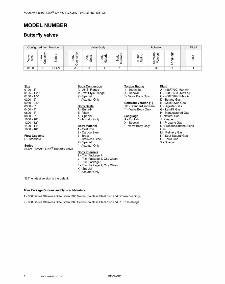
MODEL NUMBER
Butterfly valves
[1] The latest version is the default.
Trim Package Options and Typical Materials:
1 - 300 Series Stainless Steel stem, 300 Series Stainless Steel disc and Bronze bushings
2 - 300 Series Stainless Steel stem, 300 Series Stainless Steel disc and PEEK bushings
Configured Item Number Valve Body Actuator Fluid
Val
ve
Siz
e
Flo
wC
apac
ity
Ser
ies
Bod
yC
onne
ctio
n
Bod
y S
eals
Bod
yM
ater
ial
Bod
yIn
tern
als
Torq
ueR
atin
g
Sof
twar
eV
ersi
on
Lang
uage
Flu
id
0100 S SLCV - A A 1 1 - 1 1C A - I
Size0100 - 1"0125 - 1.25"0150 - 1.5"0200 - 2"0250 - 2.5"0300 - 3"0400 - 4"0600 - 6"0800 - 8"1000 - 10"1200 - 12"1400 - 14"1600 - 16"
Flow CapacityS - Standard
SeriesSLCV - SMARTLINK® Butterfly Valve
Body ConnectionA - ANSI FlangeM - "M" Style FlangeX - Special* - Actuator Only
Body SealsA - Buna-NB - VitonX - Special* - Actuator Only
Body Material1 - Cast Iron2 - Carbon Steel3 - Brass5 - Stainless SteelX - Special* - Actuator Only
Body Internals1 - Trim Package 12 - Trim Package 1, Oxy Clean5 - Trim Package 26 - Trim Package 2, Oxy CleanX - Special* - Actuator Only
Torque Rating1 - 300 in-lbs X - Special* - Valve Body Only
Software Version [1]1C - Standard software** - Valve Body Only
LanguageA - EnglishX - Special* - Valve Body Only
FluidA - 158F/70C Max AirB - 350F/177C Max AirC - 400F/204C Max AirD - Butane GasE - Coke Oven GasF - Digester GasG - Landfill GasH - Manufactured GasI - Natural GasJ - OxygenK - Propane GasL - Propane/Butane Blend GasM - Refinery GasN - Sour Natural GasO - Town GasX - Special
MAXON SMARTLINK® CV INTELLIGENT VALVE ACTUATOR
32M-06002E 3
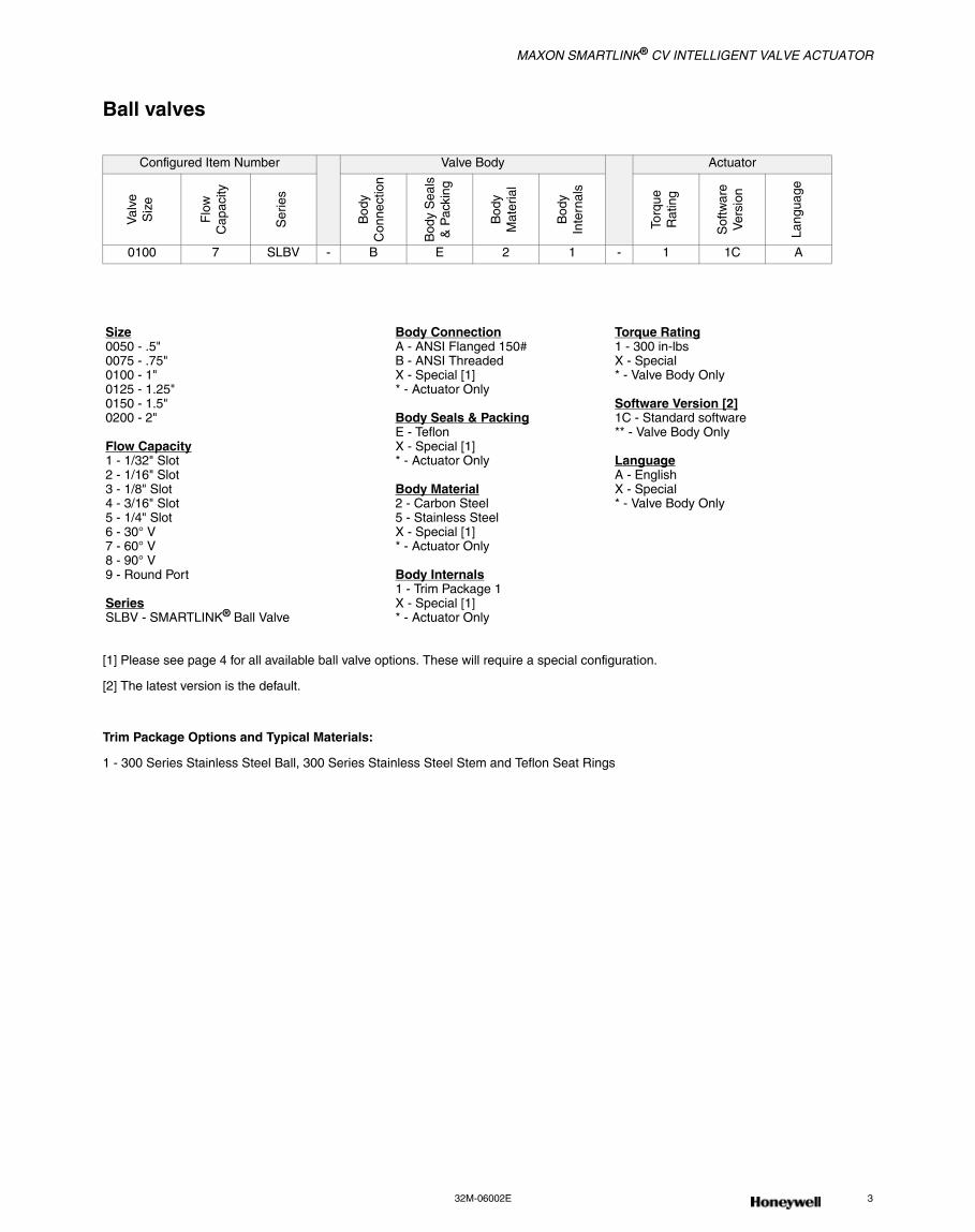
Ball valves
[1] Please see page 4 for all available ball valve options. These will require a special configuration.
[2] The latest version is the default.
Trim Package Options and Typical Materials:
1 - 300 Series Stainless Steel Ball, 300 Series Stainless Steel Stem and Teflon Seat Rings
Configured Item Number Valve Body Actuator
Val
veS
ize
Flo
wC
apac
ity
Ser
ies
Bod
yC
onne
ctio
n
Bod
y S
eals
& P
acki
ng
Bod
yM
ater
ial
Bod
yIn
tern
als
Torq
ueR
atin
g
Sof
twar
eV
ersi
on
Lang
uage
0100 7 SLBV - B E 2 1 - 1 1C A
Size0050 - .5"0075 - .75"0100 - 1"0125 - 1.25"0150 - 1.5"0200 - 2"
Flow Capacity1 - 1/32" Slot2 - 1/16" Slot3 - 1/8" Slot4 - 3/16" Slot5 - 1/4" Slot6 - 30° V7 - 60° V8 - 90° V9 - Round Port
SeriesSLBV - SMARTLINK® Ball Valve
Body ConnectionA - ANSI Flanged 150#B - ANSI ThreadedX - Special [1]* - Actuator Only
Body Seals & PackingE - TeflonX - Special [1]* - Actuator Only
Body Material2 - Carbon Steel5 - Stainless SteelX - Special [1]* - Actuator Only
Body Internals1 - Trim Package 1X - Special [1]* - Actuator Only
Torque Rating1 - 300 in-lbs X - Special* - Valve Body Only
Software Version [2]1C - Standard software** - Valve Body Only
LanguageA - EnglishX - Special* - Valve Body Only
MAXON SMARTLINK® CV INTELLIGENT VALVE ACTUATOR
4 www.maxoncorp.com 32M-06002E
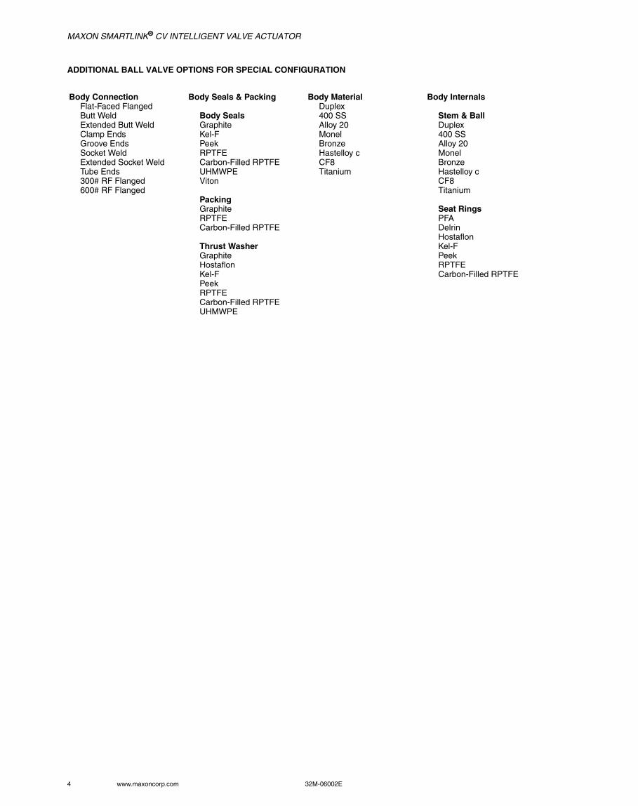
ADDITIONAL BALL VALVE OPTIONS FOR SPECIAL CONFIGURATION
Body ConnectionFlat-Faced FlangedButt WeldExtended Butt WeldClamp EndsGroove EndsSocket WeldExtended Socket WeldTube Ends300# RF Flanged600# RF Flanged
Body Seals & Packing
Body SealsGraphiteKel-FPeekRPTFECarbon-Filled RPTFEUHMWPEViton
PackingGraphiteRPTFECarbon-Filled RPTFE
Thrust WasherGraphiteHostaflonKel-FPeekRPTFECarbon-Filled RPTFEUHMWPE
Body MaterialDuplex400 SSAlloy 20MonelBronzeHastelloy cCF8Titanium
Body Internals
Stem & BallDuplex400 SSAlloy 20MonelBronzeHastelloy cCF8Titanium
Seat RingsPFADelrinHostaflonKel-FPeekRPTFECarbon-Filled RPTFE
MAXON SMARTLINK® CV INTELLIGENT VALVE ACTUATOR
32M-06002E 5
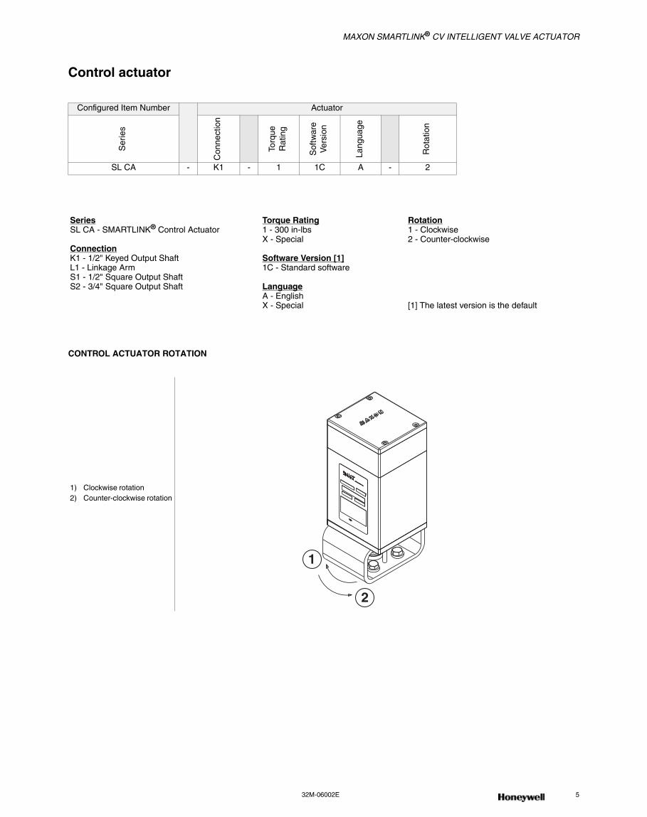
Control actuator
CONTROL ACTUATOR ROTATION
Configured Item Number Actuator
Ser
ies
Con
nect
ion
Torq
ueR
atin
g
Sof
twar
eV
ersi
on
Lang
uage
Rot
atio
n
SL CA - K1 - 1 1C A - 2
SeriesSL CA - SMARTLINK® Control Actuator
ConnectionK1 - 1/2" Keyed Output ShaftL1 - Linkage ArmS1 - 1/2" Square Output ShaftS2 - 3/4" Square Output Shaft
Torque Rating1 - 300 in-lbs X - Special
Software Version [1]1C - Standard software
LanguageA - EnglishX - Special
Rotation1 - Clockwise2 - Counter-clockwise
[1] The latest version is the default
1) Clockwise rotation2) Counter-clockwise rotation
1
2
MAXON SMARTLINK® CV INTELLIGENT VALVE ACTUATOR
6 www.maxoncorp.com 32M-06002E
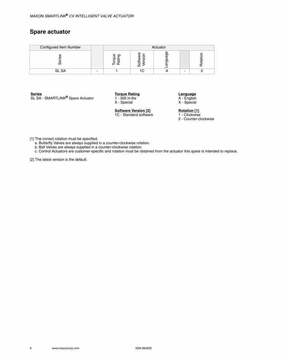
Spare actuator
[1] The correct rotation must be specified.a. Butterfly Valves are always supplied in a counter-clockwise rotation.b. Ball Valves are always supplied in a counter-clockwise rotation.c. Control Actuators are customer-specific and rotation must be obtained from the actuator this spare is intended to replace.
[2] The latest version is the default.
Configured Item Number Actuator
Ser
ies
Torq
ueR
atin
g
Sof
twar
eV
ersi
on
Lang
uage
Rot
atio
n
SL SA - 1 1C A - 2
SeriesSL SA - SMARTLINK® Spare Actuator
Torque Rating1 - 300 in-lbs X - Special
Software Version [2]1C - Standard software
LanguageA - EnglishX - Special
Rotation [1]1 - Clockwise2 - Counter-clockwise
MAXON SMARTLINK® CV INTELLIGENT VALVE ACTUATOR
32M-06002E 7
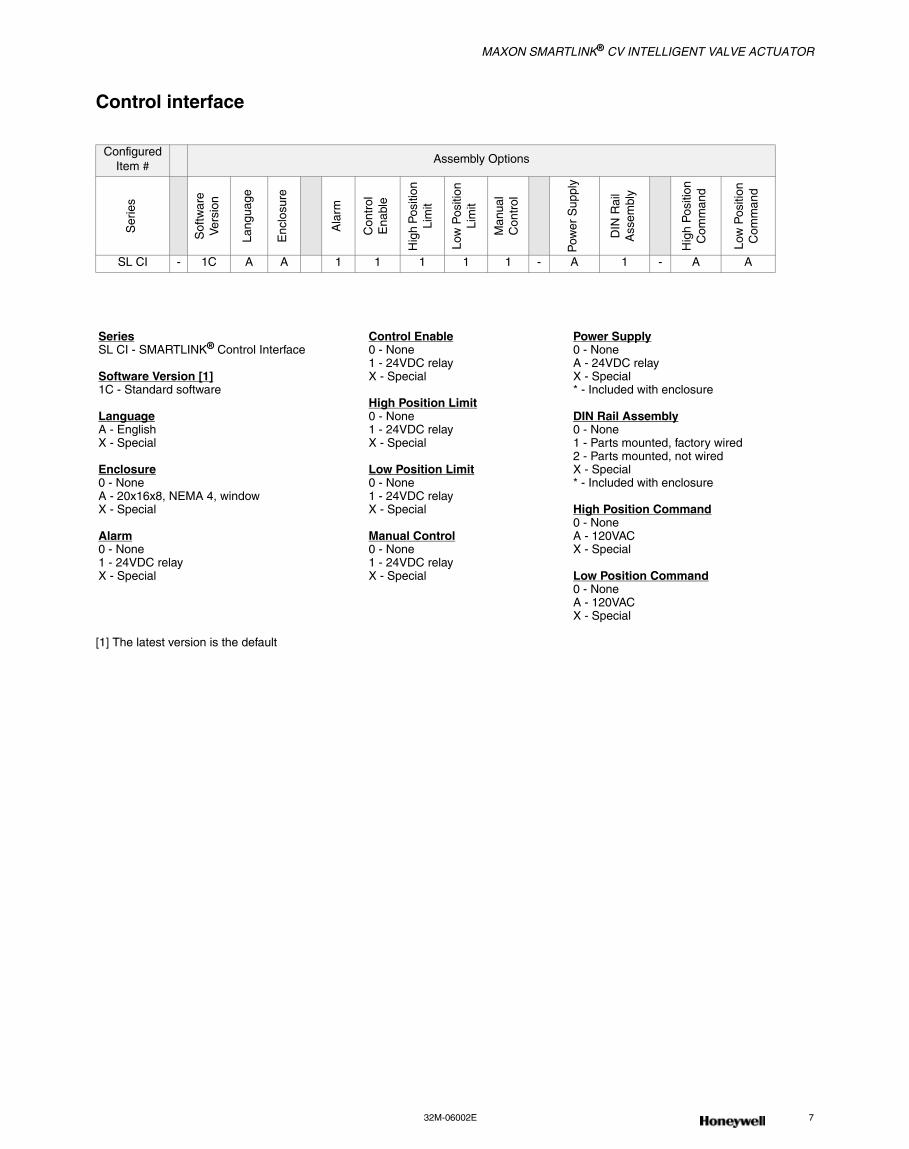
Control interface
[1] The latest version is the default
Configured Item #
Assembly Options
Ser
ies
Sof
twar
e V
ersi
on
Lang
uage
Enc
losu
re
Ala
rm
Con
trol
Ena
ble
Hig
h P
ositi
on
Lim
it
Low
Pos
ition
Lim
it
Man
ual
Con
trol
Pow
er S
uppl
y
DIN
Rai
lA
ssem
bly
Hig
h P
ositi
onC
omm
and
Low
Pos
ition
Com
man
d
SL CI - 1C A A 1 1 1 1 1 - A 1 - A A
SeriesSL CI - SMARTLINK® Control Interface
Software Version [1]1C - Standard software
LanguageA - EnglishX - Special
Enclosure0 - NoneA - 20x16x8, NEMA 4, windowX - Special
Alarm0 - None1 - 24VDC relayX - Special
Control Enable0 - None1 - 24VDC relayX - Special
High Position Limit0 - None1 - 24VDC relayX - Special
Low Position Limit0 - None1 - 24VDC relayX - Special
Manual Control0 - None1 - 24VDC relayX - Special
Power Supply0 - NoneA - 24VDC relayX - Special* - Included with enclosure
DIN Rail Assembly0 - None1 - Parts mounted, factory wired2 - Parts mounted, not wiredX - Special* - Included with enclosure
High Position Command0 - NoneA - 120VAC X - Special
Low Position Command0 - NoneA - 120VACX - Special
MAXON SMARTLINK® CV INTELLIGENT VALVE ACTUATOR
8 www.maxoncorp.com 32M-06002E
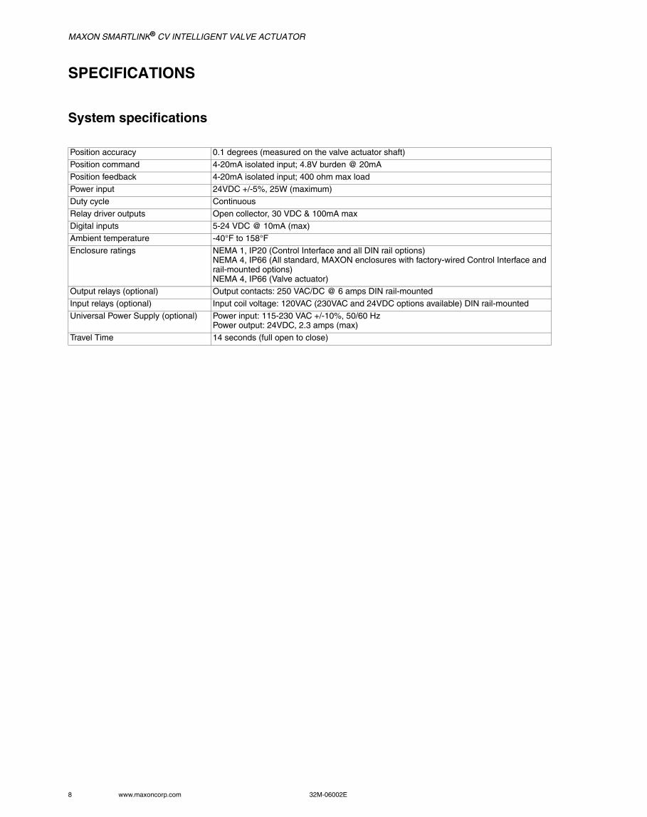
SPECIFICATIONS
System specifications
Position accuracy 0.1 degrees (measured on the valve actuator shaft)
Position command 4-20mA isolated input; 4.8V burden @ 20mA
Position feedback 4-20mA isolated input; 400 ohm max loadPower input 24VDC +/-5%, 25W (maximum)
Duty cycle Continuous
Relay driver outputs Open collector, 30 VDC & 100mA maxDigital inputs 5-24 VDC @ 10mA (max)
Ambient temperature -40°F to 158°F
Enclosure ratings NEMA 1, IP20 (Control Interface and all DIN rail options)NEMA 4, IP66 (All standard, MAXON enclosures with factory-wired Control Interface and rail-mounted options)NEMA 4, IP66 (Valve actuator)
Output relays (optional) Output contacts: 250 VAC/DC @ 6 amps DIN rail-mounted
Input relays (optional) Input coil voltage: 120VAC (230VAC and 24VDC options available) DIN rail-mounted
Universal Power Supply (optional) Power input: 115-230 VAC +/-10%, 50/60 HzPower output: 24VDC, 2.3 amps (max)
Travel Time 14 seconds (full open to close)
MAXON SMARTLINK® CV INTELLIGENT VALVE ACTUATOR
32M-06002E 9
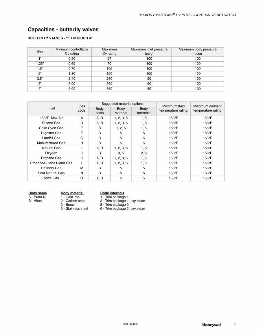
Capacities - butterfly valvesBUTTERFLY VALVES - 1” THROUGH 4”
SizeMinimum controllable
Cv ratingMaximumCv rating
Maximum inlet pressure(psig)
Maximum body pressure(psig)
1” 0.50 27 100 100
1.25” 0.60 70 100 100 1.5” 0.70 105 100 100
2” 1.30 190 100 100
2.5” 2.40 260 90 100
3” 3.00 360 60 100 4” 5.00 750 30 100
FluidGascode
Suggested material optionsMaximum fluid
temperature ratingMaximum ambient temperature ratingBody
sealsBody
materialBody
internals
158°F Max Air A A, B 1, 2, 3, 5 1, 5 158°F 158°F
Butane Gas D A, B 1, 2, 3, 5 1, 5 158°F 158°F Coke Oven Gas E B 1, 2, 5 1, 5 158°F 158°F
Digester Gas F B 5 5 158°F 158°F
Landfill Gas G B 5 5 158°F 158°F Manufactured Gas H B 5 5 158°F 158°F
Natural Gas I A, B 1, 2, 3, 5 1, 5 158°F 158°F
Oxygen J B 3, 5 2, 6 158°F 158°F Propane Gas K A, B 1, 2, 3, 5 1, 5 158°F 158°F
Propane/Butane Blend Gas L A, B 1, 2, 3, 5 1, 5 158°F 158°F
Refinery Gas M B 5 5 158°F 158°F Sour Natural Gas N B 5 5 158°F 158°F
Town Gas O A, B 5 5 158°F 158°F
Body sealsA - Buna-NB - Viton
Body material1 - Cast iron2 - Carbon steel3 - Brass5 - Stainless steel
Body internals1 - Trim package 12 - Trim package 1, oxy clean5 - Trim package 26 - Trim package 2, oxy clean
MAXON SMARTLINK® CV INTELLIGENT VALVE ACTUATOR
10 www.maxoncorp.com 32M-06002E
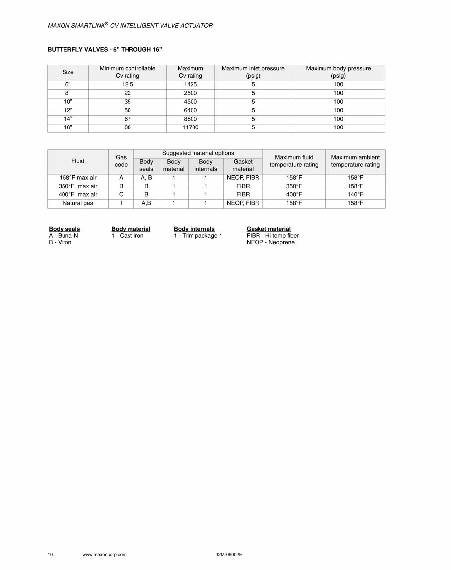
BUTTERFLY VALVES - 6” THROUGH 16”
SizeMinimum controllable
Cv ratingMaximumCv rating
Maximum inlet pressure(psig)
Maximum body pressure(psig)
6” 12.5 1425 5 100
8” 22 2500 5 100 10” 35 4500 5 100
12” 50 6400 5 100
14” 67 8800 5 100
16” 88 11700 5 100
FluidGascode
Suggested material optionsMaximum fluid
temperature ratingMaximum ambienttemperature ratingBody
sealsBody
materialBody
internalsGasketmaterial
158°F max air A A, B 1 1 NEOP, FIBR 158°F 158°F
350°F max air B B 1 1 FIBR 350°F 158°F
400°F max air C B 1 1 FIBR 400°F 140°F Natural gas I A,B 1 1 NEOP, FIBR 158°F 158°F
Body sealsA - Buna-NB - Viton
Body material1 - Cast iron
Body internals1 - Trim package 1
Gasket materialFIBR - Hi temp fiberNEOP - Neoprene
MAXON SMARTLINK® CV INTELLIGENT VALVE ACTUATOR
32M-06002E 11
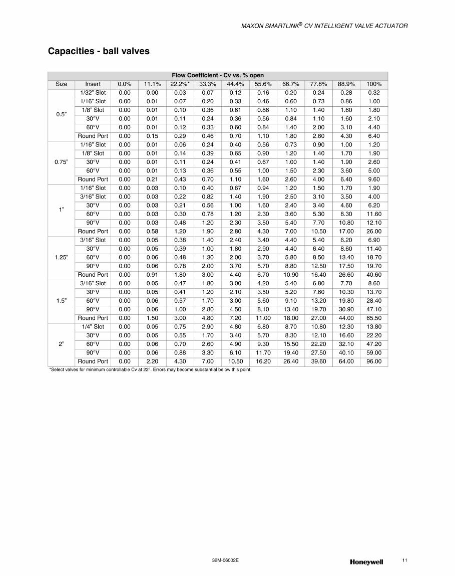
Capacities - ball valves
Flow Coefficient - Cv vs. % openSize Insert 0.0% 11.1% 22.2%* 33.3% 44.4% 55.6% 66.7% 77.8% 88.9% 100%
0.5”
1/32” Slot 0.00 0.00 0.03 0.07 0.12 0.16 0.20 0.24 0.28 0.32
1/16” Slot 0.00 0.01 0.07 0.20 0.33 0.46 0.60 0.73 0.86 1.00
1/8” Slot 0.00 0.01 0.10 0.36 0.61 0.86 1.10 1.40 1.60 1.8030°V 0.00 0.01 0.11 0.24 0.36 0.56 0.84 1.10 1.60 2.10
60°V 0.00 0.01 0.12 0.33 0.60 0.84 1.40 2.00 3.10 4.40
Round Port 0.00 0.15 0.29 0.46 0.70 1.10 1.80 2.60 4.30 6.40
0.75”
1/16” Slot 0.00 0.01 0.06 0.24 0.40 0.56 0.73 0.90 1.00 1.201/8” Slot 0.00 0.01 0.14 0.39 0.65 0.90 1.20 1.40 1.70 1.90
30°V 0.00 0.01 0.11 0.24 0.41 0.67 1.00 1.40 1.90 2.60
60°V 0.00 0.01 0.13 0.36 0.55 1.00 1.50 2.30 3.60 5.00Round Port 0.00 0.21 0.43 0.70 1.10 1.60 2.60 4.00 6.40 9.60
1”
1/16” Slot 0.00 0.03 0.10 0.40 0.67 0.94 1.20 1.50 1.70 1.90
3/16” Slot 0.00 0.03 0.22 0.82 1.40 1.90 2.50 3.10 3.50 4.0030°V 0.00 0.03 0.21 0.56 1.00 1.60 2.40 3.40 4.60 6.20
60°V 0.00 0.03 0.30 0.78 1.20 2.30 3.60 5.30 8.30 11.60
90°V 0.00 0.03 0.48 1.20 2.30 3.50 5.40 7.70 10.80 12.10Round Port 0.00 0.58 1.20 1.90 2.80 4.30 7.00 10.50 17.00 26.00
1.25”
3/16” Slot 0.00 0.05 0.38 1.40 2.40 3.40 4.40 5.40 6.20 6.90
30°V 0.00 0.05 0.39 1.00 1.80 2.90 4.40 6.40 8.60 11.4060°V 0.00 0.06 0.48 1.30 2.00 3.70 5.80 8.50 13.40 18.70
90°V 0.00 0.06 0.78 2.00 3.70 5.70 8.80 12.50 17.50 19.70
Round Port 0.00 0.91 1.80 3.00 4.40 6.70 10.90 16.40 26.60 40.60
1.5”
3/16” Slot 0.00 0.05 0.47 1.80 3.00 4.20 5.40 6.80 7.70 8.60
30°V 0.00 0.05 0.41 1.20 2.10 3.50 5.20 7.60 10.30 13.70
60°V 0.00 0.06 0.57 1.70 3.00 5.60 9.10 13.20 19.80 28.4090°V 0.00 0.06 1.00 2.80 4.50 8.10 13.40 19.70 30.90 47.10
Round Port 0.00 1.50 3.00 4.80 7.20 11.00 18.00 27.00 44.00 65.50
2”
1/4” Slot 0.00 0.05 0.75 2.90 4.80 6.80 8.70 10.80 12.30 13.8030°V 0.00 0.05 0.55 1.70 3.40 5.70 8.30 12.10 16.60 22.20
60°V 0.00 0.06 0.70 2.60 4.90 9.30 15.50 22.20 32.10 47.20
90°V 0.00 0.06 0.88 3.30 6.10 11.70 19.40 27.50 40.10 59.00Round Port 0.00 2.20 4.30 7.00 10.50 16.20 26.40 39.60 64.00 96.00
*Select valves for minimum controllable Cv at 22°. Errors may become substantial below this point.
MAXON SMARTLINK® CV INTELLIGENT VALVE ACTUATOR
12 www.maxoncorp.com 32M-06002E
MATERIALS OF CONSTRUCTION
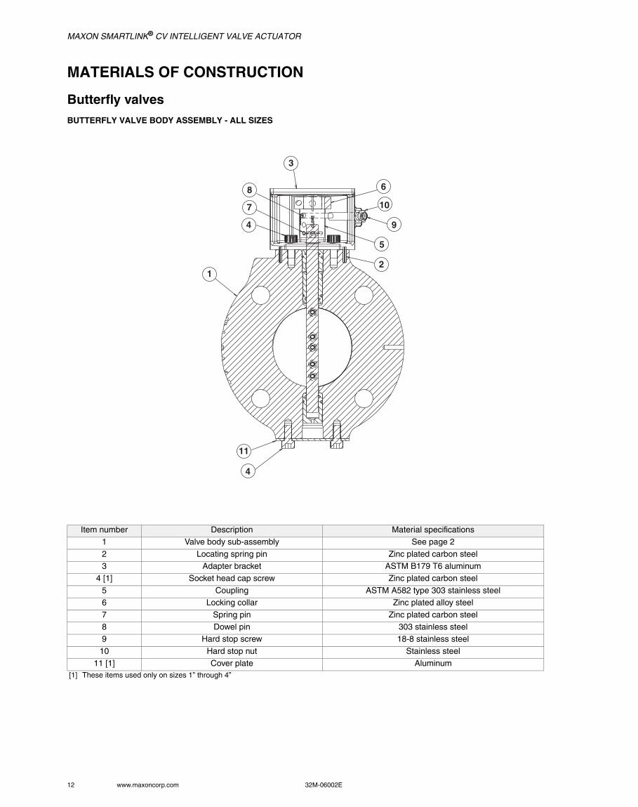
Butterfly valvesBUTTERFLY VALVE BODY ASSEMBLY - ALL SIZES
Item number Description Material specifications
1 Valve body sub-assembly See page 2
2 Locating spring pin Zinc plated carbon steel3 Adapter bracket ASTM B179 T6 aluminum
4 [1] Socket head cap screw Zinc plated carbon steel
5 Coupling ASTM A582 type 303 stainless steel6 Locking collar Zinc plated alloy steel
7 Spring pin Zinc plated carbon steel
8 Dowel pin 303 stainless steel9 Hard stop screw 18-8 stainless steel
10 Hard stop nut Stainless steel
11 [1] Cover plate Aluminum[1] These items used only on sizes 1” through 4”
3
8
7
4
6
10
9
5
2
11
4
1
MAXON SMARTLINK® CV INTELLIGENT VALVE ACTUATOR
32M-06002E 13
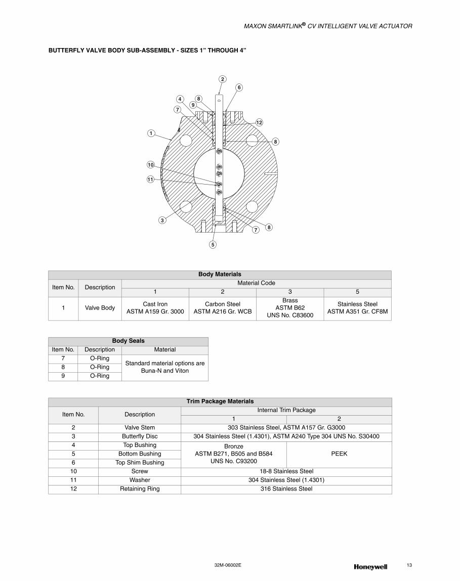
BUTTERFLY VALVE BODY SUB-ASSEMBLY - SIZES 1” THROUGH 4”
Body Materials
Item No. DescriptionMaterial Code
1 2 3 5
1 Valve BodyCast Iron
ASTM A159 Gr. 3000Carbon Steel
ASTM A216 Gr. WCB
BrassASTM B62
UNS No. C83600
Stainless SteelASTM A351 Gr. CF8M
Body SealsItem No. Description Material
7 O-RingStandard material options are
Buna-N and Viton8 O-Ring
9 O-Ring
Trim Package Materials
Item No. DescriptionInternal Trim Package
1 2
2 Valve Stem 303 Stainless Steel, ASTM A157 Gr. G3000
3 Butterfly Disc 304 Stainless Steel (1.4301), ASTM A240 Type 304 UNS No. S304004 Top Bushing Bronze
ASTM B271, B505 and B584UNS No. C93200
PEEK5 Bottom Bushing
6 Top Shim Bushing10 Screw 18-8 Stainless Steel
11 Washer 304 Stainless Steel (1.4301)
12 Retaining Ring 316 Stainless Steel
4 89
2
6
1
12
10
11
3
5
7
87
8
MAXON SMARTLINK® CV INTELLIGENT VALVE ACTUATOR
14 www.maxoncorp.com 32M-06002E
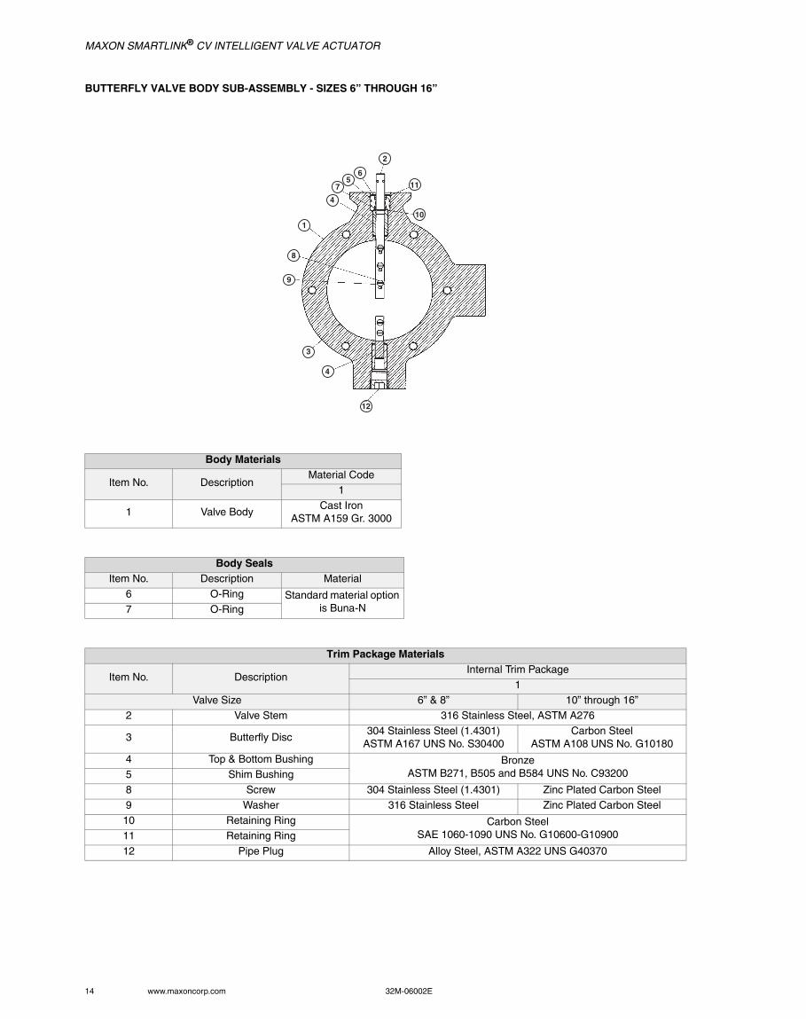
BUTTERFLY VALVE BODY SUB-ASSEMBLY - SIZES 6” THROUGH 16”
Body Materials
Item No. DescriptionMaterial Code
1
1 Valve BodyCast Iron
ASTM A159 Gr. 3000
Body SealsItem No. Description Material
6 O-Ring Standard material option is Buna-N7 O-Ring
Trim Package Materials
Item No. DescriptionInternal Trim Package
1Valve Size 6” & 8” 10” through 16”
2 Valve Stem 316 Stainless Steel, ASTM A276
3 Butterfly Disc304 Stainless Steel (1.4301)
ASTM A167 UNS No. S30400Carbon Steel
ASTM A108 UNS No. G10180
4 Top & Bottom Bushing BronzeASTM B271, B505 and B584 UNS No. C932005 Shim Bushing
8 Screw 304 Stainless Steel (1.4301) Zinc Plated Carbon Steel
9 Washer 316 Stainless Steel Zinc Plated Carbon Steel10 Retaining Ring Carbon Steel
SAE 1060-1090 UNS No. G10600-G1090011 Retaining Ring
12 Pipe Plug Alloy Steel, ASTM A322 UNS G40370
2
56
7
1
4
8
9
11
10
3
4
12
MAXON SMARTLINK® CV INTELLIGENT VALVE ACTUATOR
32M-06002E 15
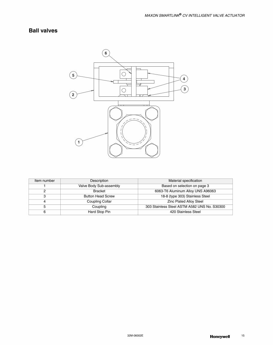
Ball valves
Item number Description Material specification
1 Valve Body Sub-assembly Based on selection on page 3
2 Bracket 6063-T6 Aluminum Alloy UNS A960633 Button Head Screw 18-8 (type 303) Stainless Steel
4 Coupling Collar Zinc Plated Alloy Steel
5 Coupling 303 Stainless Steel ASTM A582 UNS No. S303006 Hard Stop Pin 420 Stainless Steel
6
5
2
4
3
1
MAXON SMARTLINK® CV INTELLIGENT VALVE ACTUATOR
16 www.maxoncorp.com 32M-06002E
DIMENSIONS AND WEIGHTS
Butterfly valves
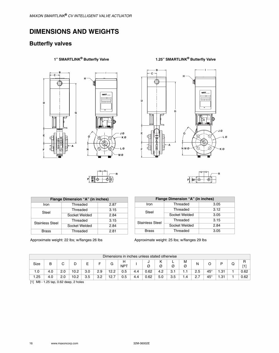
1” SMARTLINK® Butterfly Valve 1.25” SMARTLINK® Butterfly Valve
Approximate weight: 22 lbs; w/flanges 26 lbs Approximate weight: 25 lbs; w/flanges 29 lbs
Dimensions in inches unless stated otherwise
Size B C D E F GH
NPTI
JØ
KØ
LØ
MØ
N O P QR[1]
1.0 4.0 2.0 10.2 3.0 2.9 12.2 0.5 4.4 0.62 4.2 3.1 1.1 2.5 45° 1.31 1 0.62
1.25 4.0 2.0 10.2 3.5 3.2 12.7 0.5 4.4 0.62 5.0 3.5 1.4 2.7 45° 1.31 1 0.62 [1] M8 - 1.25 tap, 0.62 deep, 2 holes
B
D
C
E
A
G
F
I
N
J Ø
K Ø
L Ø
M Ø
R
P
Q Q
H
O
BC
D
E
F
A
G
H
I
O
N M Ø
J Ø
L Ø
K Ø
P
QQR
Flange Dimension “A” (in inches)Iron Threaded 2.87
SteelThreaded 3.15
Socket Welded 2.84
Stainless SteelThreaded 3.15
Socket Welded 2.84
Brass Threaded 2.81
Flange Dimension “A” (in inches)Iron Threaded 3.05
SteelThreaded 3.12
Socket Welded 3.05
Stainless SteelThreaded 3.15
Socket Welded 2.84
Brass Threaded 3.05
MAXON SMARTLINK® CV INTELLIGENT VALVE ACTUATOR
32M-06002E 17
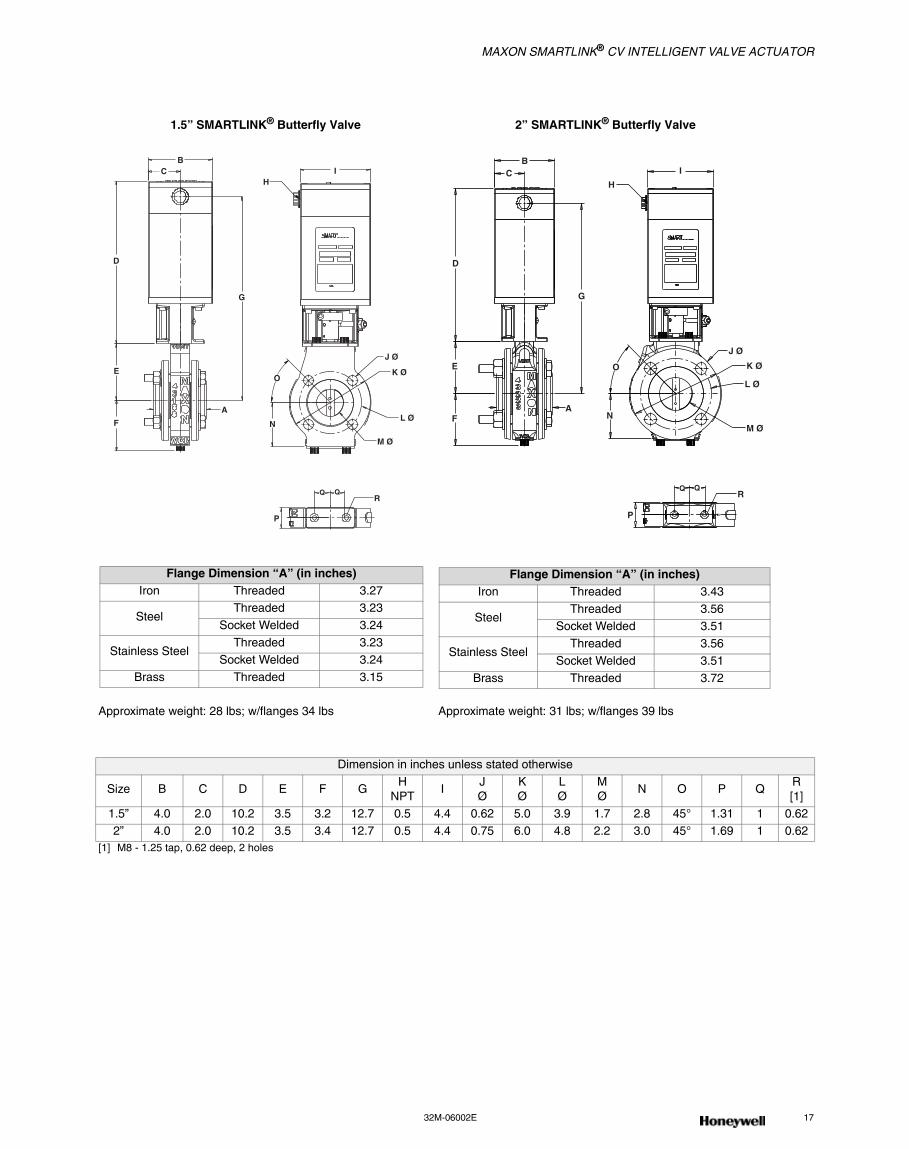
1.5” SMARTLINK® Butterfly Valve 2” SMARTLINK® Butterfly Valve
Approximate weight: 28 lbs; w/flanges 34 lbs Approximate weight: 31 lbs; w/flanges 39 lbs
Dimension in inches unless stated otherwise
Size B C D E F GH
NPTI
JØ
KØ
LØ
MØ
N O P QR[1]
1.5” 4.0 2.0 10.2 3.5 3.2 12.7 0.5 4.4 0.62 5.0 3.9 1.7 2.8 45° 1.31 1 0.62 2” 4.0 2.0 10.2 3.5 3.4 12.7 0.5 4.4 0.75 6.0 4.8 2.2 3.0 45° 1.69 1 0.62
[1] M8 - 1.25 tap, 0.62 deep, 2 holes
C
D
G
E
F
A
O
N
J Ø
K Ø
L Ø
M Ø
P
RQ Q
BI
H
BC
D
G
E
FA
O
N
J Ø
K Ø
L Ø
M Ø
P
RQQ
1"
I
H
Flange Dimension “A” (in inches)Iron Threaded 3.27
SteelThreaded 3.23
Socket Welded 3.24
Stainless SteelThreaded 3.23
Socket Welded 3.24
Brass Threaded 3.15
Flange Dimension “A” (in inches)Iron Threaded 3.43
SteelThreaded 3.56
Socket Welded 3.51
Stainless SteelThreaded 3.56
Socket Welded 3.51
Brass Threaded 3.72
MAXON SMARTLINK® CV INTELLIGENT VALVE ACTUATOR
18 www.maxoncorp.com 32M-06002E
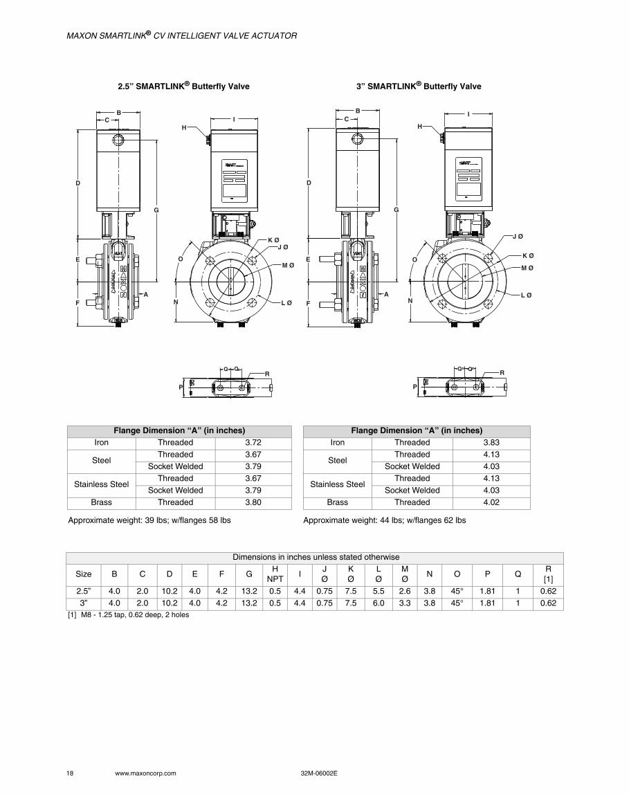
2.5” SMARTLINK® Butterfly Valve 3” SMARTLINK® Butterfly Valve
Approximate weight: 39 lbs; w/flanges 58 lbs Approximate weight: 44 lbs; w/flanges 62 lbs
Dimensions in inches unless stated otherwise
Size B C D E F GH
NPTI
JØ
KØ
LØ
MØ
N O P QR[1]
2.5” 4.0 2.0 10.2 4.0 4.2 13.2 0.5 4.4 0.75 7.5 5.5 2.6 3.8 45° 1.81 1 0.62
3” 4.0 2.0 10.2 4.0 4.2 13.2 0.5 4.4 0.75 7.5 6.0 3.3 3.8 45° 1.81 1 0.62 [1] M8 - 1.25 tap, 0.62 deep, 2 holes
A
BC
D
G
IH
E
F
O
N
K ØJ Ø
M Ø
L Ø
P
RQ Q
BC
D
G
E
FA
O
N
J Ø
K Ø
M Ø
L Ø
P
RQ Q
I
H
Flange Dimension “A” (in inches)Iron Threaded 3.72
SteelThreaded 3.67
Socket Welded 3.79
Stainless SteelThreaded 3.67
Socket Welded 3.79
Brass Threaded 3.80
Flange Dimension “A” (in inches)Iron Threaded 3.83
SteelThreaded 4.13
Socket Welded 4.03
Stainless SteelThreaded 4.13
Socket Welded 4.03
Brass Threaded 4.02
MAXON SMARTLINK® CV INTELLIGENT VALVE ACTUATOR
32M-06002E 19
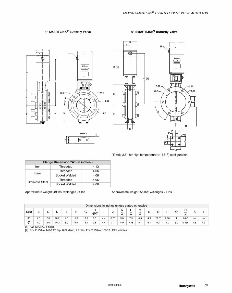
4” SMARTLINK® Butterfly Valve 6” SMARTLINK® Butterfly Valve
[1] Add 2.5” for high temperature (>158°F) configuration
Approximate weight: 49 lbs; w/flanges 71 lbs Approximate weight: 55 lbs; w/flanges 71 lbs
Dimensions in inches unless stated otherwise
Size B C D E F GH
NPTI J
KØ
LØ
MØ
N O P QR[2]
S T
4” 4.0 2.0 10.2 4.6 5.3 13.8 0.5 4.4 0.75 9.0 7.5 4.3 4.9 22.5° 2.06 1 0.62 --- ---
6” 4.0 2.0 10.2 5.9 5.9 15.1 0.5 4.4 [1] 8.9 7.75 6.1 6.1 60° 1.0 3.0 0.438 1.5 4.3
[1] 1/2-13 UNC, 6 holes[2] For 4” Valve: M8-1.25 tap, 0.62 deep, 2 holes. For 6” Valve: 1/2-13 UNC, 4 holes
BC
D
G
HI
E
F A
K Ø
O
N
M Ø
L Ø
J Ø
P
RQ Q
BC
D [1]
G [1]
H
I
E
F
ST
K Ø
M Ø
J Ø
L Ø
O
N
PP
PP
R
Q
Q
Flange Dimension “A” (in inches )Iron Threaded 4.13
SteelThreaded 4.06
Socket Welded 4.06
Stainless SteelThreaded 4.06
Socket Welded 4.06
MAXON SMARTLINK® CV INTELLIGENT VALVE ACTUATOR
20 www.maxoncorp.com 32M-06002E
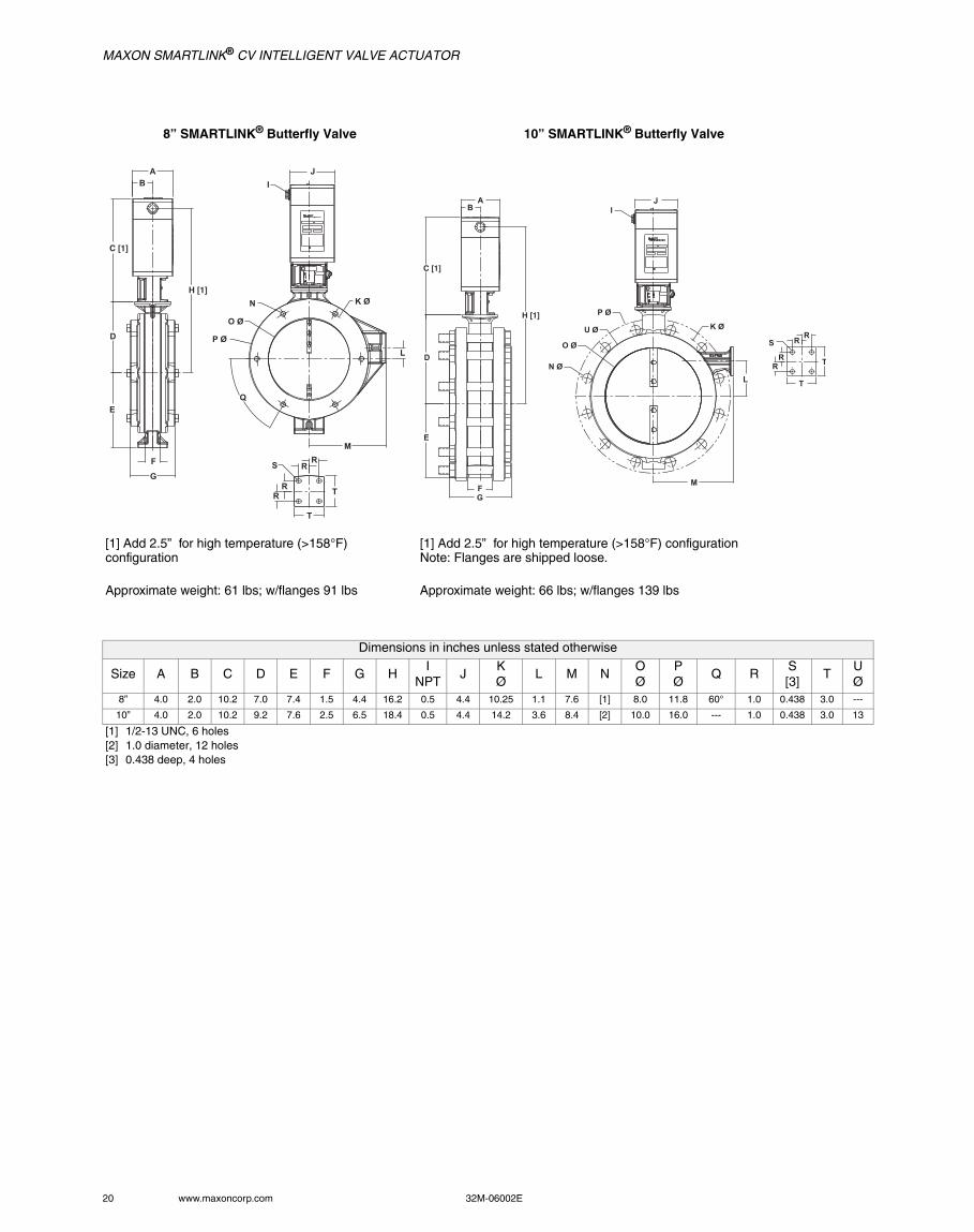
8” SMARTLINK® Butterfly Valve 10” SMARTLINK® Butterfly Valve
[1] Add 2.5” for high temperature (>158°F) configuration
[1] Add 2.5” for high temperature (>158°F) configurationNote: Flanges are shipped loose.
Approximate weight: 61 lbs; w/flanges 91 lbs Approximate weight: 66 lbs; w/flanges 139 lbs
Dimensions in inches unless stated otherwise
Size A B C D E F G HI
NPTJ
KØ
L M NOØ
PØ
Q RS[3]
TUØ
8” 4.0 2.0 10.2 7.0 7.4 1.5 4.4 16.2 0.5 4.4 10.25 1.1 7.6 [1] 8.0 11.8 60° 1.0 0.438 3.0 ---
10” 4.0 2.0 10.2 9.2 7.6 2.5 6.5 18.4 0.5 4.4 14.2 3.6 8.4 [2] 10.0 16.0 --- 1.0 0.438 3.0 13
[1] 1/2-13 UNC, 6 holes[2] 1.0 diameter, 12 holes[3] 0.438 deep, 4 holes
AB
C [1]
D
H [1]
E
F
G
I
J
K Ø
L
N
O Ø
P Ø
Q
M
S
T
T
RR
RR
JI
AB
C [1]
H [1]
D
E
FG
P Ø
U Ø
O Ø
N Ø
K Ø
L
M
SR
R
RR T
T

MAXON SMARTLINK® CV INTELLIGENT VALVE ACTUATOR
32M-06002E 21
12” SMARTLINK® Butterfly Valve[1] Add 2.5” for high temperature (>158°F) configurationNote: Flanges are shipped loose.
Approximate weight: 77 lbs; w/flanges 197 lbs
14” SMARTLINK® Butterfly Valve[1] Add 2.5” for high temperature (>158°F) configurationNote: Flanges are shipped loose.
Approximate weight: 109 lbs; w/flanges 266 lbs
Dimensions in inches unless stated otherwise
Size A B C D E F G HI
NPTJ
KØ
L MNØ
OØ
PØ
RS[1]
TUØ
12” 4.0 2.0 10.2 10.2 8.7 3.0 7.6 19.4 0.5 4.4 17.0 4.6 9.5 1.0 12.0 19.0 1.0 0.438 3.0 16.0
14” 4.0 2.0 10.2 11.4 9.6 3.0 7.6 20.6 0.5 4.4 18.8 5.8 10.5 1.1 13.2 21.0 1.0 0.438 3.0 17.4
[1] 0.438 deep, 4 holes
JI
AB
C [1]
D
H [1]
E
FG
K ØP Ø
N Ø
U Ø
O Ø
L
M
SR
R
RR
T
T
2
AB
C [1]
D
H [1]
E
FG
IJ
P ØK Ø
U Ø
O Ø
N Ø
M
L
SR
R
RR
T
T
MAXON SMARTLINK® CV INTELLIGENT VALVE ACTUATOR
22 www.maxoncorp.com 32M-06002E
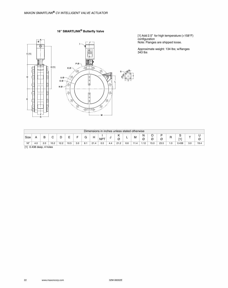
16” SMARTLINK® Butterfly Valve[1] Add 2.5” for high temperature (>158°F) configurationNote: Flanges are shipped loose.
Approximate weight: 134 lbs; w/flanges 343 lbs
Dimensions in inches unless stated otherwise
Size A B C D E F G HI
NPTJ
KØ
L MNØ
OØ
PØ
RS[1]
TUØ
16” 4.0 2.0 10.2 12.2 10.5 3.0 8.1 21.4 0.5 4.4 21.2 6.6 11.4 1.12 15.0 23.5 1.0 0.438 3.0 19.4
[1] 0.438 deep, 4 holes
JI
AB
C [1]
D
H [1]
E
FG
P Ø
K Ø
U Ø
O Ø
N Ø
M
L
S RR
RR
T
T
MAXON SMARTLINK® CV INTELLIGENT VALVE ACTUATOR
32M-06002E 23
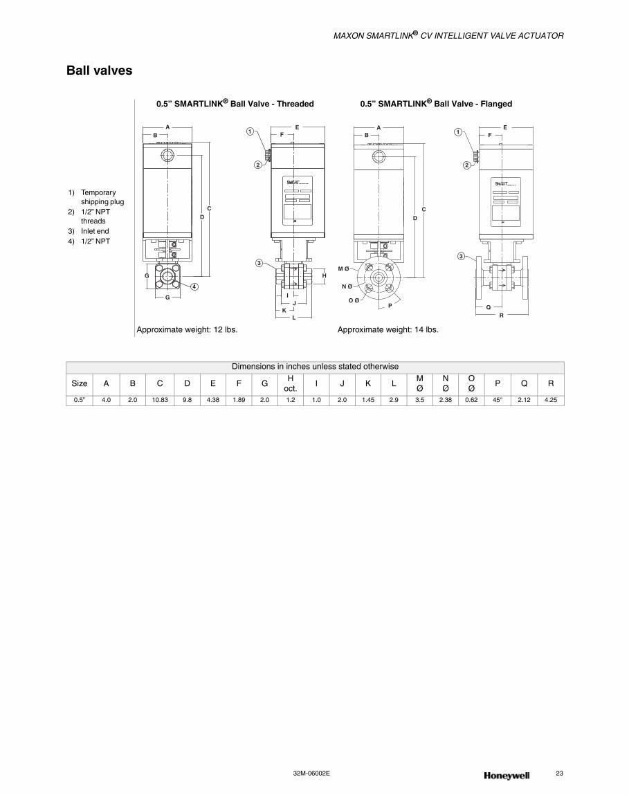
Ball valves
1) Temporary shipping plug
2) 1/2” NPT threads
3) Inlet end4) 1/2” NPT
0.5” SMARTLINK® Ball Valve - Threaded 0.5” SMARTLINK® Ball Valve - Flanged
Approximate weight: 12 lbs. Approximate weight: 14 lbs.
Dimensions in inches unless stated otherwise
Size A B C D E F GH
oct.I J K L
MØ
NØ
OØ
P Q R
0.5” 4.0 2.0 10.83 9.8 4.38 1.89 2.0 1.2 1.0 2.0 1.45 2.9 3.5 2.38 0.62 45° 2.12 4.25
AB
CD
G
G
4
3
H
IJ
KL
2
EF1
AB
C
EF1
2
D
M Ø
N Ø
O ØP
3
QR
MAXON SMARTLINK® CV INTELLIGENT VALVE ACTUATOR
24 www.maxoncorp.com 32M-06002E
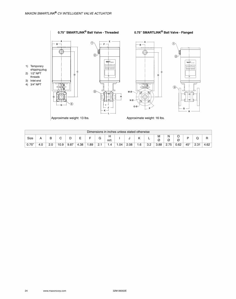
1) Temporary shipping plug
2) 1/2” NPT threads
3) Inlet end4) 3/4” NPT
0.75” SMARTLINK® Ball Valve - Threaded 0.75” SMARTLINK® Ball Valve - Flanged
Approximate weight: 13 lbs. Approximate weight: 16 lbs.
Dimensions in inches unless stated otherwise
Size A B C D E F GH
oct.I J K L
MØ
NØ
OØ
P Q R
0.75” 4.0 2.0 10.9 9.87 4.38 1.89 2.1 1.4 1.04 2.08 1.6 3.2 3.88 2.75 0.62 45° 2.31 4.62
AB
CD
1
2
EF
G
G 4
3
H
IJ
KL
AB
1
2
CD
3
QR
M Ø
N Ø
O ØP
MAXON SMARTLINK® CV INTELLIGENT VALVE ACTUATOR
32M-06002E 25
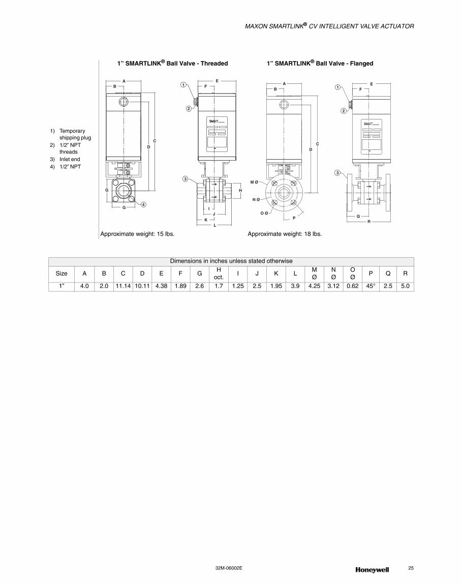
1) Temporary shipping plug
2) 1/2” NPT threads
3) Inlet end4) 1/2” NPT
1” SMARTLINK® Ball Valve - Threaded 1” SMARTLINK® Ball Valve - Flanged
Approximate weight: 15 lbs. Approximate weight: 18 lbs.
Dimensions in inches unless stated otherwise
Size A B C D E F GH
oct.I J K L
MØ
NØ
OØ
P Q R
1” 4.0 2.0 11.14 10.11 4.38 1.89 2.6 1.7 1.25 2.5 1.95 3.9 4.25 3.12 0.62 45° 2.5 5.0
AB
CD
EF1
2
G
G4
3
H
IJ
KL
AB
CD
EF1
2
3
QR
M Ø
N Ø
O ØP

MAXON SMARTLINK® CV INTELLIGENT VALVE ACTUATOR
26 www.maxoncorp.com 32M-06002E
1) Temporary shipping plug
2) 1/2” NPT threads
3) Inlet end4) 1-1/4” NPT5) 150# ANSI
flange
1.25” SMARTLINK® Ball Valve - Threaded 1.25” SMARTLINK® Ball Valve - Flanged
Approximate weight: 16.5 lbs. Approximate weight: 21.5 lbs.
Dimensions in inches unless stated otherwise
Size A B C D E F G H I J K L MN
oct.OØ
PØ
QØ
R S T
1.25” 4.0 2.0 11.06 10.03 4.38 1.88 2.9 1.91 1.47 1.5 3.0 2.2 4.4 2.1 3.5 .62 4.62 45° 2.75 5.5
O C
AB
CD
H
I
G
G
4
3
JK
LM
N
2
1 EF
O C
AB
CD
3
2
1 EF
5
ST
P ∅
O ∅
R
Q ∅
MAXON SMARTLINK® CV INTELLIGENT VALVE ACTUATOR
32M-06002E 27
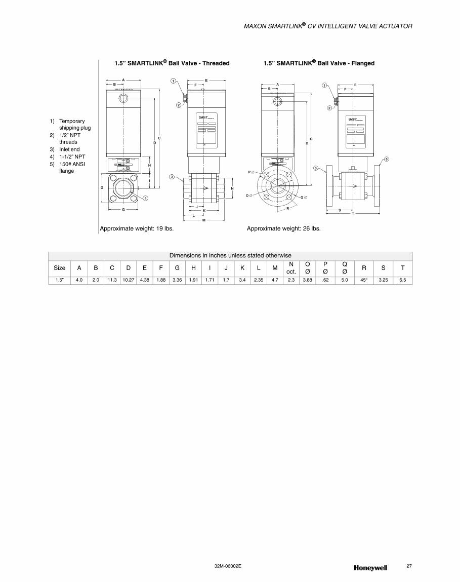
1) Temporary shipping plug
2) 1/2” NPT threads
3) Inlet end4) 1-1/2” NPT5) 150# ANSI
flange
1.5” SMARTLINK® Ball Valve - Threaded 1.5” SMARTLINK® Ball Valve - Flanged
Approximate weight: 19 lbs. Approximate weight: 26 lbs.
Dimensions in inches unless stated otherwise
Size A B C D E F G H I J K L MN
oct.OØ
PØ
QØ
R S T
1.5” 4.0 2.0 11.3 10.27 4.38 1.88 3.36 1.91 1.71 1.7 3.4 2.35 4.7 2.3 3.88 .62 5.0 45° 3.25 6.5
O C
AB
CD
H
I
4
G
G
3
JK
LM
N
1
2
EF
O C
AB
CD
3
1
2
EF
P ∅
O ∅ Q ∅
R ST
5
MAXON SMARTLINK® CV INTELLIGENT VALVE ACTUATOR
28 www.maxoncorp.com 32M-06002E
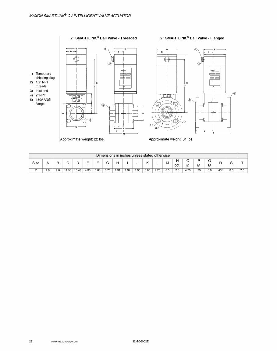
1) Temporary shipping plug
2) 1/2” NPT threads
3) Inlet end4) 2” NPT5) 150# ANSI
flange
2” SMARTLINK® Ball Valve - Threaded 2” SMARTLINK® Ball Valve - Flanged
Approximate weight: 22 lbs. Approximate weight: 31 lbs.
Dimensions in inches unless stated otherwise
Size A B C D E F G H I J K L MN
oct.OØ
PØ
QØ
R S T
2” 4.0 2.0 11.53 10.49 4.38 1.88 3.75 1.91 1.94 1.90 3.80 2.75 5.5 2.8 4.75 .75 6.0 45° 3.5 7.0
O C
AB
CD
H
I
G
G
4
3
JK
LM
N
1
2
EF
AB
CD
3
1
2
EF
ST
R
P ∅O ∅
Q ∅
5
MAXON SMARTLINK® CV INTELLIGENT VALVE ACTUATOR
32M-06002E 29
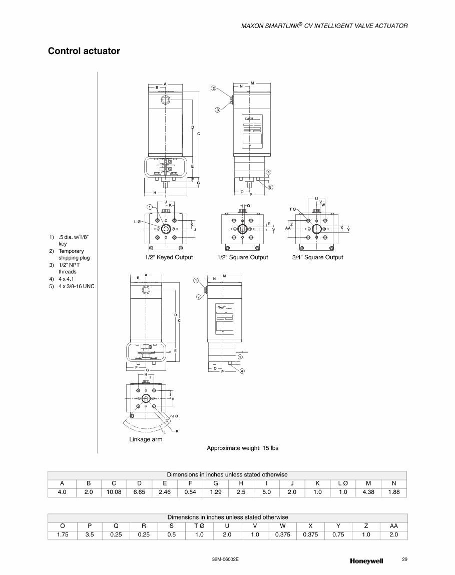
Control actuator
1) .5 dia. w/1/8” key
2) Temporary shipping plug
3) 1/2” NPT threads
4) 4 x 4.15) 4 x 3/8-16 UNC
1/2” Keyed Output 1/2” Square Output 3/4” Square Output
Linkage arm
Approximate weight: 15 lbs
Dimensions in inches unless stated otherwise
A B C D E F G H I J K L Ø M N
4.0 2.0 10.08 6.65 2.46 0.54 1.29 2.5 5.0 2.0 1.0 1.0 4.38 1.88
Dimensions in inches unless stated otherwise
O P Q R S T Ø U V W X Y Z AA1.75 3.5 0.25 0.25 0.5 1.0 2.0 1.0 0.375 0.375 0.75 1.0 2.0
AB
C
D
E
FG
HI
1J
K
KJ
L Ø
MN2
3
4
5O
P
Q
RS
T Ø
UVW
X YZ
AA
AB
C
D
E
FG
HI
IH
J Ø
KL
MN1
2
3
4O
P
MAXON SMARTLINK® CV INTELLIGENT VALVE ACTUATOR
30 www.maxoncorp.com 32M-06002E
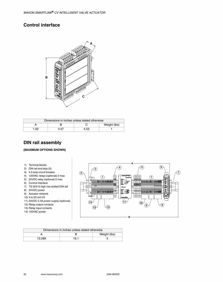
Control interface
DIN rail assembly (MAXIMUM OPTIONS SHOWN)
Dimensions in inches unless stated otherwiseA B C Weight (lbs)
1.00 4.57 4.53 1
1) Terminal blocks2) DIN rail end stop (5)3) 4.0 amp circuit breaker4) 120VAC relays (optional) 2 max.5) 24VDC relay (optional) 5 max.6) Control interface7) TS 35X15 high rise slotted DIN rail8) 24VDC power9) Actuator network10) 4 to 20 mA I/O11) 24VDC 2.3A power supply (optional)12) Relay output contacts13) Relay input contacts14) 120VAC power
Dimensions in inches unless stated otherwise
A B Weight (lbs) 13.289 16.1 5
A
B
C
2
B
A
1
3 4 5
1
6
7
891011
1213
14
MAXON SMARTLINK® CV INTELLIGENT VALVE ACTUATOR
32M-06002E 31
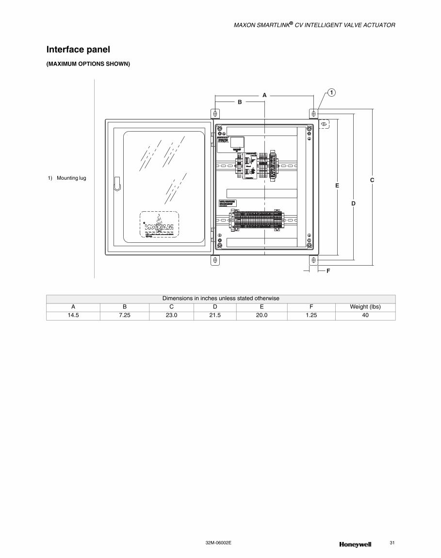
Interface panel (MAXIMUM OPTIONS SHOWN)
1) Mounting lug
Dimensions in inches unless stated otherwise
A B C D E F Weight (lbs)
14.5 7.25 23.0 21.5 20.0 1.25 40
E
D
C
F
AB
1
MAXON SMARTLINK® CV INTELLIGENT VALVE ACTUATOR
32 www.maxoncorp.com 32M-06002E
INSTALLATION INSTRUCTIONS
Mechanical installationREQUIRED COMPONENTSThe minimum SMARTLINK® system requires 1 Control Interface and 1 Valve Actuator assembly.
The SMARTLINK® Control Interface shall be mounted within a tool-secured enclosure which meets the requirements of EN 60079-0 and EN-60079-15 and is capable of accepting the applicable wiring methods specified in EN 60079-14. Where installed in outdoor and potentially wet locations, the enclosure shall, at a minimum, meet the requirements of IP54. Where installed in locations providing adequate protection against the entry of solid foreign objects or water capable of impairing safety, the enclosure shall, at a minimum, meet the requirements of IP4X.
OPTIONAL COMPONENTSDIN rail-mounted interface relays, 24VDC supply, terminal block assembly, a pre-wired DIN rail assembly and a NEMA 4 enclosed panel are all options available from MAXON.
Mechanical installation of the SMARTLINK® Intelligent Valve and Actuator Assembly requires the following:
• Mount the SMARTLINK® Control Interface along with any optional interface relays on a DIN rail within an appropriate electrical enclo-sure or cabinet, and
• Install the SMARTLINK® Valve Actuator assembly in any orientation within the pipe train.
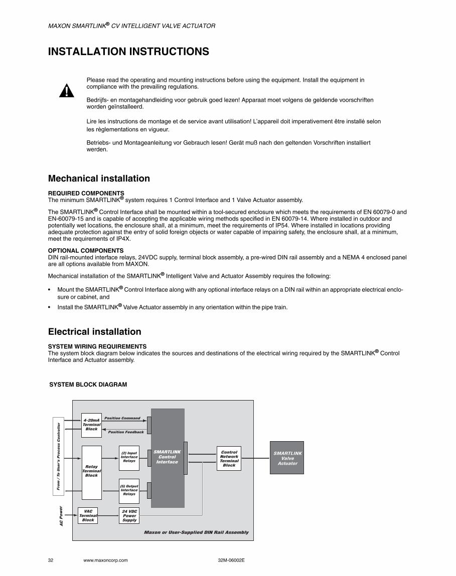
Electrical installationSYSTEM WIRING REQUIREMENTSThe system block diagram below indicates the sources and destinations of the electrical wiring required by the SMARTLINK® Control Interface and Actuator assembly.
Please read the operating and mounting instructions before using the equipment. Install the equipment in compliance with the prevailing regulations.
Bedrijfs- en montagehandleiding voor gebruik goed lezen! Apparaat moet volgens de geldende voorschriften worden geïnstalleerd.
Lire les instructions de montage et de service avant utilisation! L’appareil doit imperativement être installé selon les règlementations en vigueur.
Betriebs- und Montageanleitung vor Gebrauch lesen! Gerät muß nach den geltenden Vorschriften installiert werden.
SYSTEM BLOCK DIAGRAM
4-20mATerminal
Block
RelayTerminal
Block
ControlNetworkTerminal
Block
Position Command
Position Feedback
(2) InputInterface
Relays
(5) OutputInterface
Relays
24 VDCPowerSupply
SMARTLINKControl
Interface
SMARTLINKValve
Actuator
Fro
m /
To U
ser'
s P
rocess C
ontr
oll
er
Maxon or User-Supplied DIN Rail Assembly
VACTerminal
Block
AC
Pow
er
MAXON SMARTLINK® CV INTELLIGENT VALVE ACTUATOR
32M-06002E 33
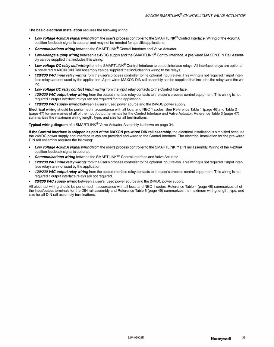
The basic electrical installation requires the following wiring:
• Low voltage 4-20mA signal wiring from the user’s process controller to the SMARTLINK® Control Interface. Wiring of the 4-20mA position feedback signal is optional and may not be needed for specific applications.
• Communications wiring between the SMARTLINK® Control Interface and Valve Actuator.
• Low-voltage supply wiring between a 24VDC supply and the SMARTLINK® Control Interface. A pre-wired MAXON DIN Rail Assem-bly can be supplied that includes this wiring.
• Low voltage DC relay coil wiring from the SMARTLINK® Control Interface to output interface relays. All interface relays are optional. A pre-wired MAXON DIN Rail Assembly can be supplied that includes this wiring to the relays.
• 120/230 VAC input relay wiring from the user's process controller to the optional input relays. This wiring is not required if input inter-face relays are not used by the application. A pre-wired MAXON DIN rail assembly can be supplied that includes the relays and the wir-ing.
• Low voltage DC relay contact input wiring from the input relay contacts to the Control Interface.
• 120/230 VAC output relay wiring from the output interface relay contacts to the user’s process control equipment. This wiring is not required if output interface relays are not required for the application.
• 120/230 VAC supply wiring between a user’s fused power source and the 24VDC power supply.Electrical wiring should be performed in accordance with all local and NEC 1 codes. See Reference Table 1 (page 46)and Table 2 (page 47) for summaries of all of the input/output terminals for the Control Interface and Valve Actuator. Reference Table 3 (page 47) summarizes the maximum wiring length, type, and size for all terminations.
Typical wiring diagram of a SMARTLINK® Valve Actuator Assembly is shown on page 34.
If the Control Interface is shipped as part of the MAXON pre-wired DIN rail assembly, the electrical installation is simplified because the 24VDC power supply and interface relays are provided and wired to the Control Interface. The electrical installation for the pre-wired DIN rail assembly requires the following:
• Low voltage 4-20mA signal wiring from the user’s process controller to the SMARTLINK™ DIN rail assembly. Wiring of the 4-20mA position feedback signal is optional.
• Communications wiring between the SMARTLINK™ Control Interface and Valve Actuator.
• 120/230 VAC input relay wiring from the user's process controller to the optional input relays. This wiring is not required if input inter-face relays are not used by the application.
• 120/230 VAC output relay wiring from the output interface relay contacts to the user’s process control equipment. This wiring is not required if output interface relays are not required.
• 20/230 VAC supply wiring between a user’s fused power source and the 24VDC power supply.All electrical wiring should be performed in accordance with all local and NEC 1 codes. Reference Table 4 (page 48) summarizes all of the input/output terminals for the DIN rail assembly and Reference Table 5 (page 49) summarizes the maximum wiring length, type, and size for all DIN rail assembly terminations.
MAXON SMARTLINK® CV INTELLIGENT VALVE ACTUATOR
34 www.maxoncorp.com 32M-06002E
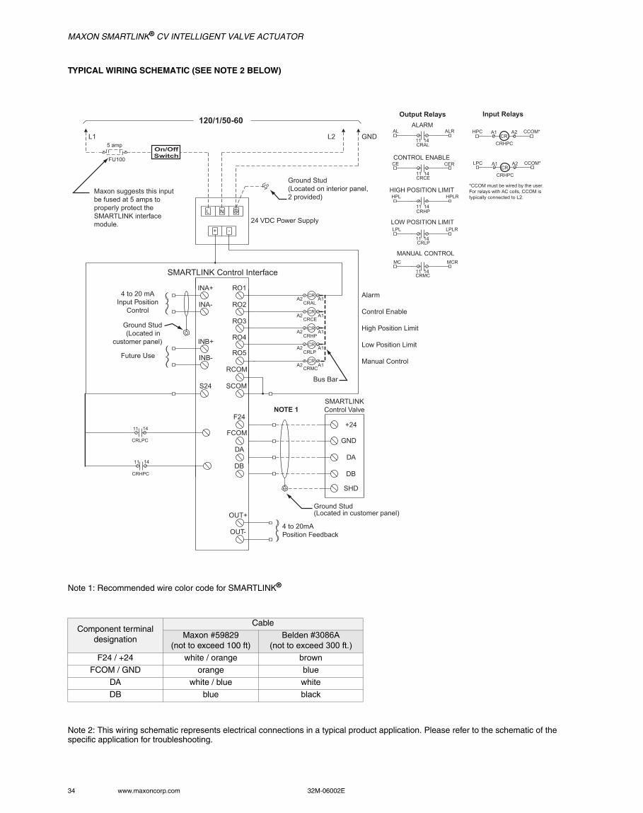
TYPICAL WIRING SCHEMATIC (SEE NOTE 2 BELOW)
Note 1: Recommended wire color code for SMARTLINK®
Note 2: This wiring schematic represents electrical connections in a typical product application. Please refer to the schematic of the specific application for troubleshooting.
Component terminal designation
Cable
Maxon #59829(not to exceed 100 ft)
Belden #3086A(not to exceed 300 ft.)
F24 / +24 white / orange brown
FCOM / GND orange blue
DA white / blue white
DB blue black
CRALCR
CRCECR
CRHPCR
CRLPCR
CRMCCR
CRMC11 14
CRLP11 14
CRHP11 14
CRCE11 14
AL
CRAL11 14
ALR
CER
HPLR
LPLR
MCR
CE
HPL
LPL
MC
ALARM
LOW POSITION LIMIT
MANUAL CONTROL
HIGH POSITION LIMIT
CONTROL ENABLE
A1
A1
A1
A1
A1
A2
A2
A2
A2
A2
11 14
CRHPC
11 14
CRLPC
Output Relays Input Relays
HPCCR
A1 A2 CCOM*
CRHPC
LPCCR
A1 A2 CCOM*
CRHPC
*CCOM must be wired by the user.For relays with AC coils, CCOM is typically connected to L2.
Maxon suggests this input be fused at 5 amps to properly protect the SMARTLINK interfacemodule.
120/1/50-60
L1 L2 GND
Ground Stud(Located on interior panel, 2 provided)
24 VDC Power Supply
SMARTLINK Control Interface
INA+4 to 20 mA
Input PositionControl
Future Use
INA-
INB+
INB-
RO1
RO2
RO3
RO4
RO5
RCOM
SCOM
FCOM
DA
DB
OUT+
OUT-
F24
GND
DA
DB
SHD
+24
S24
Ground Stud(Located in customer panel)
4 to 20mAPosition Feedback
SMARTLINKControl ValveNOTE 1
Bus Bar
Alarm
Control Enable
High Position Limit
Low Position Limit
Manual Control
FU100
5 amp
L N
+ -
Ground Stud(Located in
customer panel)
On/OffSwitch
MAXON SMARTLINK® CV INTELLIGENT VALVE ACTUATOR
32M-06002E 35
OPERATING INSTRUCTIONSInstructions provided by the company or individual responsible for the manufacture and/or overall installation of a complete system incorporating MAXON products take precedence over the installation and operating instructions provided by MAXON. If any of the instructions provided by MAXON are in conflict with local codes or regulations, please contact MAXON before initial start-up of equipment.
The installer should perform the following commissioning steps for the SMARTLINK® Control Interface and Actuator Assembly:
• Wiring checkout prior to applying power
• Operational checkout after applying power
• System configuration if required by the application• Valve characterization if required by the application
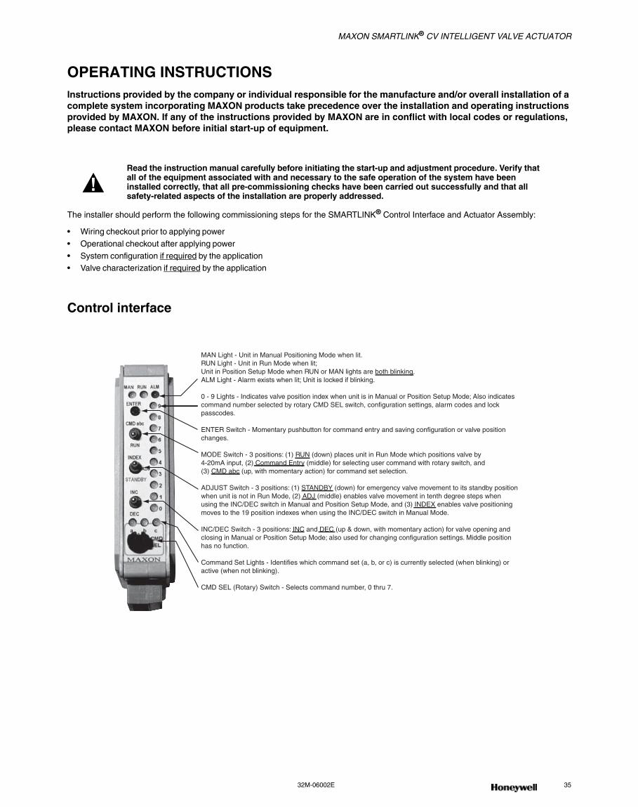
Control interface
Read the instruction manual carefully before initiating the start-up and adjustment procedure. Verify that all of the equipment associated with and necessary to the safe operation of the system have been installed correctly, that all pre-commissioning checks have been carried out successfully and that all safety-related aspects of the installation are properly addressed.
MAN Light - Unit in Manual Positioning Mode when lit.RUN Light - Unit in Run Mode when lit; Unit in Position Setup Mode when RUN or MAN lights are both blinking.ALM Light - Alarm exists when lit; Unit is locked if blinking.
0 - 9 Lights - Indicates valve position index when unit is in Manual or Position Setup Mode; Also indicates command number selected by rotary CMD SEL switch, configuration settings, alarm codes and lock passcodes.
ENTER Switch - Momentary pushbutton for command entry and saving configuration or valve position changes.
MODE Switch - 3 positions: (1) RUN (down) places unit in Run Mode which positions valve by 4-20mA input, (2) Command Entry (middle) for selecting user command with rotary switch, and (3) CMD abc (up, with momentary action) for command set selection.
ADJUST Switch - 3 positions: (1) STANDBY (down) for emergency valve movement to its standby position when unit is not in Run Mode, (2) ADJ (middle) enables valve movement in tenth degree steps when using the INC/DEC switch in Manual and Position Setup Mode, and (3) INDEX enables valve positioning moves to the 19 position indexes when using the INC/DEC switch in Manual Mode.
INC/DEC Switch - 3 positions: INC and DEC (up & down, with momentary action) for valve opening and closing in Manual or Position Setup Mode; also used for changing configuration settings. Middle position has no function.
Command Set Lights - Identifies which command set (a, b, or c) is currently selected (when blinking) or active (when not blinking).
CMD SEL (Rotary) Switch - Selects command number, 0 thru 7.
MAXON SMARTLINK® CV INTELLIGENT VALVE ACTUATOR
36 www.maxoncorp.com 32M-06002E
Wiring checkoutBefore applying power to the SMARTLINK® Control Interface and SMARTLINK® Valve Actuator Assembly, perform the following wiring checkout:
1. Verify that 120 VAC is not connected directly to SMARTLINK® Control Interface and Valve Actuator Assembly. Both devices are pow-ered by a 24VDC supply. All output interface relay wiring from the Control Interface is connected to 24VDC relay coils.
2. Verify the proper wire type and maximum wire length requirements are satisfied for all connections.
3. Verify color code connections are correct on the 24V/Data Connector of both the Control Interface and Valve Actuator Assembly.4. Measure the resistance between earth ground at the user's panel enclosing the Control Interface and each of the four signals wired to
the Valve Actuator: F24 (Field +24VDC), FCOM (Field Common), DA (Data-A), and DB (Data-B). The resistance should indicate an open circuit (i.e., a resistance value greater than 106 Ohms). If an open circuit is not measured, damage or incorrect wiring of the con-trol network cable exists and must be corrected.
5. Verify proper termination of shields for the 4-20mA cables and the control cable between the Control Interface and Valve Actuator Assembly.
6. If MAXON SMARTLINK® Interface Relays are not provided with the Control Interface, verify that all required relays have a coil rating less than 30VDC and 100mA. The output interface relay coils are connected to the Control Interface, RO1 through RO5 terminals of the Relay Output driver connector.
Refer to SMARTLINK® Reference Tables 1 through 5 (page 46 through page 49) for all termination definitions and wiring/shielding requirements.
Maintain the integrity of the MAXON enclosure by using NEMA 4 or IP66 rated dust- and water-tight electrical connectors. Use cable-sealing grips and strain-relief loops for any cord or cable. Use internal sealing materials on all conduit connections. Moisture can have a harmful effect on device internals if permitted to enter through wiring connectors. Ensure that the device connection is not at a low point of the conduit to avoid condensation run-off into the housing; install a drip loop if necessary. Make sure that the access cover plate is in place and securely fastened. All cover screws should be tightened using an alternate cross-corner tightening pattern. Cover screws should be checked periodically to ensure adequate sealing protection.
Operational checkoutApply power to the SMARTLINK® Control Interface and SMARTLINK® Valve Actuator Assembly and perform the following operational checkout:
1. Verify the Control Interface Alarm light is off and the Run light is on after powering up the system. If the alarm light is on, see page 43 to determine the cause of the alarm and corrective actions.
2. Place the user’s process controller into manual mode or temporarily replace the 4-20mA position command with a simulated 4-20mA current loop. With the Control Interface command switch in the “RUN” position, move the position command signal slowly from 4mA to 20mA and verify valve movement. The position of the valve can be visually observed by the “OPEN” or “CLOSED” markings on the machined coupling that connects the actuator to the valve shaft. If the application requires the 4-20mA position feedback signal, mea-sure this feedback current loop while changing the position command and verify that the two currents (input vs. output) are approxi-mately equal after pausing at several intermediate positions.
3. If the process controller cannot be placed in manual mode or if a simulated command signal cannot be produced, the SMARTLINK® assembly can be placed in a local manual mode. (Refer to Command A-0 and the general command entry instructions on page 37). Once the system is in manual mode, drive the valve to its full open and closed positions using the INC/DEC switch on the Control Interface.
4. If installed, verify operation of each output interface relay by measuring the presence and disappearance of voltage on the relay’s con-tact. If a DIN Rail Assembly is supplied with the Control Interface, the terminals for each relay contact are shown in Reference Table 6 on page 50. The Control Interface relay driver output terminals are also provided in Reference Table 6 to assist in testing of interface relays when not supplied and pre-wired by MAXON.
Do not remove power from an air valve actuator when both 1) the valve is open more than 30 degrees, and 2) the blower is running. Prior to power loss, ensure that the valve position is less than 30 degrees open, and/or that the blower has stopped. Failure to observe these precautions can result in permanent damage to the valve actuator.
MAXON SMARTLINK® CV INTELLIGENT VALVE ACTUATOR
32M-06002E 37
User commandsThere are 3 SMARTLINK® command sets (a, b, and c) as listed below. Entry requirements for each command (if applicable) are listed at right. Detailed descriptions of the following user commands are shown in Reference Tables 8 through 10 (page 52 through page 57).
Command Set "A" A-0........ Enter Manual Positioning Mode.................. Position command <= 4 mAA-1........ Display Alarm CodesA-2........ Enter Valve Position Setup Mode ............... Position command = 4 to 20 mAA-3........ Reserved for future useA-4........ Reserved for future useA-5........ Set Max Position and Min/Max Ramp ......... Position command = 20 mAA-6........ Set Min Position and Min/Max Ramp .......... Position command = 4 mAA-7........ Unlock Valve Configuration ........................ Unit must be "locked"
Command Set "B" B-0........ Select Loss of Signal PositionB-1........ Reserved for future useB-2........ Select Standby PositionB-3........ Select DeadbandB-4........ Set High Limit Position Threshold ............... Unit in Manual ModeB-5........ Set Low Limit Position ThresholdUnit in Manual ModeB-6........ Set Auto Ramp Adjust On/OffB-7........ Reserved for future use
Command Set "C" C-0 ....... Check Valve CalibrationFor MAXON-trained technician onlyC-1 ....... Calibrate Valve .............................. For MAXON-trained technician onlyC-2 ....... Enable Valve Calibration / Check................ For MAXON-trained technician onlyC-3 ....... Reset Factory Default Settings ................... Unit in Position Setup ModeC-4 ....... Enter New Lock Combination ..................... Unit “unlocked” to modifyC-5 ....... Select Lock Enable / Disable ...................... Unit "unlocked" to modifyC-6 ....... Save Profile as BackupC-7 ....... Restore Backup Profile .............................. Unit in Position Setup Mode
GENERAL COMMAND ENTRY INSTRUCTIONS:1. A user command can be performed only when the following conditions are all satisfied:
a) MODE switch is not in the RUN position,b) one of the green command set lights (a, b, c) is blinking,c) ADJUST switch is not in the STANDBY position, andd) unit is “unlocked”. (Condition ‘d’ is not required for Command A-7, Unlock Valve Configuration and Command A-1, Display Alarm Codes.)e) For some commands, the unit must be in a specific mode or have the correct 4-20 mA command signal (see command entry requirements listed above or in Reference Tables 8 through 10 on page 52 through page 57).
2. If the a, b, or c command set light is not blinking, momentarily push the MODE switch in the CMD abc position (up) or, change the posi-tion of the rotary CMD SEL switch. This will start the command set light blinking and permit a command to be entered.
3. Select the desired command set by momentarily pushing the MODE switch upward to the CMD abc position. Subsequent CMD abc switch entries will change the command set selection as indicated by the green command set (a, b, c) lights.
4. Select the desired command number by changing the position of the rotary CMD SEL switch. When one of the command set lights is blinking, the command number selected is indicated by the corresponding numbered (0-9) light being lit.
5. After the command set and number are selected, press the ENTER button. If all of the numbered lights flash momentarily after the ENTER button is pushed, a command entry error has occurred and the command was not executed. If an entry error occurs, check if the unit is locked (i.e. alarm light blinking) or the ADJUST switch is in the STANDBY position. If neither condition exists, check the spe-cific entry requirements of the command.
MAXON SMARTLINK® CV INTELLIGENT VALVE ACTUATOR
38 www.maxoncorp.com 32M-06002E
SYSTEM CONFIGURATIONThere are 8 SMARTLINK® configuration settings that can be changed through execution of the commands below, using the switches and lights on the Control Interface. Detailed explanations of each setting appear in Reference Table 7: SMARTLINK™ System Configuration Summary on page 51.
Command Name Command Number Factory DefaultSelect LOS Position B-0 No position changeSelect Standby Position B-2 Position Index 0Select Control Deadband B-3 0.06% DeadbandSet High Limit Position Threshold B-4 80.0 degreesSet Low Limit Position Threshold B-5 0.0 degreesSet Auto Ramp Adjust On/Off B-6 Auto Ramp ONEnter New Lock Combination C-4 Passcode: 0, 0, 0, 0Select Lock Enable/Disable C-5 Lock Disable
Review the factory default settings before changing any of the system configuration settings; in many applications, modification of the default settings is not necessary. If a setting does need to be changed, follow the procedure outlined below.
1. Select and enter the required system configuration command.
2. After the command is entered, one of the numbered (0-9) lights will be on, indicating the current configuration setting. (For example: If the lock configuration is set to #0, Lock Disable, the 0 light will be solidly lit after Command C-5, Lock Enable/Disable, is entered suc-cessfully.)
3. Select the desired configuration setting by using the INC/DEC switch. As the INC/DEC switch is momentarily pushed up or down, the selected setting changes as indicated by turning on the corresponding numbered light (0-9).
4. Push the ENTER button after the desired configuration setting is selected. The numbered light that is lit to indicate the selected config-uration will momentarily turn off indicating the command is complete and the configuration setting is saved.
5. To confirm the correct setting is saved, re-enter the command and verify the new setting by the numbered light (0-9) indication.
MAXON SMARTLINK® CV INTELLIGENT VALVE ACTUATOR
32M-06002E 39
Valve characterizationValve characterization is necessary for changing the relationship between valve position and the 4-20mA position command. This process permits field adjustment of the “installed” valve characteristic without mechanically adjusting the valve or external linkages.
The SMARTLINK® is pre-set to a linear slope, but can be customized using either the 10 Point Characterization procedure or the 19 Point Characterization procedure.
10 POINT CHARACTERIZATIONSMARTLINK® is shipped with the configuration setting to easily adjust valve positions at 10 of the 19 position indexes and automatically set the positions at the other 9 (intermediate) indexes.
1. Place the process controller that commands SMARTLINK® in manual mode and connect a 4-digit current meter on the 4-20mA posi-tion output. Execute Command B-6 and verify the Auto Ramp function is set to #1, Auto Ramp ON. If not set correctly, refer to page 38 or Reference Table 7 on page 51.
2. Execute Command A-2, Enter Position Setup Mode. In this mode, both the yellow and green run lights will be flashing. The position command signal determines which of the 19 position indexes can be modified as shown by the blinking numbered lights. Move the pro-cess controller’s output to either 0% (Index #0) or 100% (Index #9) to begin characterization.
3. With the ADJUST switch in the middle (ADJ) position, push the INC/DEC switch up or down to change the valve position. Each push of the INC/DEC switch moves the valve 0.1 degrees. If the switch is held in the up or down position for more than 3 seconds, the valve will move in 0.5-degree steps up to a total travel of 8 degrees from the stored valve position. (All the numbered lights will momentarily flash when this 8-degree limit is reached.) After moving the valve to the desired position, press the ENTER button to save the position set-ting. Record the valve position feedback in mA or %.
4. Move the controller’s output to the % or mA setting in the commissioning table (shown on page 40) for each consecutive whole digit index and repeat the adjustment procedure in Step 3. With the auto ramp function ON, adjustment at only the 10 whole digit indexes is necessary because positions at the intermediate indexes (0.5, 1.5, etc.) are automatically set to a value half way between the posi-tions of the whole number indexes (0, 1, 2, etc).
5. Execute Command C-6 to save the profile as a backup. Move the MODE switch to the RUN position and put the user’s process control-ler in AUTO.
19 POINT CHARACTERIZATIONThere are applications that require precision adjustment throughout the actuator’s control range. For these applications, adjustment of all 19 positions is necessary using the procedure below.
1. Place the process controller that commands SMARTLINK® in manual mode and connect a 4-digit current meter on the 4-20mA posi-tion output. Execute Command B-6 and set the auto ramp function to setting #0, Auto Ramp OFF. (Refer to page 38 or the Reference Table 7 on page 51 for changing configuration settings.)
2. Execute Command A-2, Enter Position Setup Mode. In this mode, both the yellow and green run lights will be flashing. The position command signal determines which of the 19 position indexes can be modified as shown by the blinking numbered lights. Move the pro-cess controller’s output to either 0% (Index #0) or 100% (Index #9) to begin characterization.
3. With the ADJUST switch in the middle (ADJ) position, push the INC/DEC switch up or down to change the valve position. Each push of the INC/DEC switch moves the valve 0.1 degrees. If the switch is held in the up or down position for more than 3 seconds, the valve will move in 0.5-degree steps up to a total travel of 8 degrees from the stored valve position. (All the numbered lights will momentarily flash when this 8-degree limit is reached.) After moving the valve to the desired position, press the ENTER button to save the position set-ting. Record the valve position feedback in mA or %.
4. Move the controller’s output to the next % or mA setting in the commissioning table (shown on page 40) and repeat the adjustment pro-cedure in Step 3 for all 19 position indexes. With the auto ramp function OFF, the positions of adjacent indexes are not automatically ramped. Therefore, all 19 position indexes should be visited during this procedure and adjusted if necessary.
5. Execute Command C-6 to save the profile as a backup. Move the MODE switch to the RUN position and put the user’s process control-ler in AUTO.
If an unsafe operating condition is observed while characterizing the SMARTLINK® in a parallel positioning combustion application, follow the instructions below:
1. When SMARTLINK® is in the Position Setup Mode for valve characterization, the ADJUST switch can be pushed to the STANDBY position (down). This action will immediately move the valve to the Standby position, overriding the 4-20mA position command.
2. The factory default Standby position is the valve position at Index #0, the minimum position in the profile. While the ADJUST switch is in this position, no commands can be executed. The Standby position function is inhibited when the MODE switch is in the RUN position (down).
MAXON SMARTLINK® CV INTELLIGENT VALVE ACTUATOR
40 www.maxoncorp.com 32M-06002E
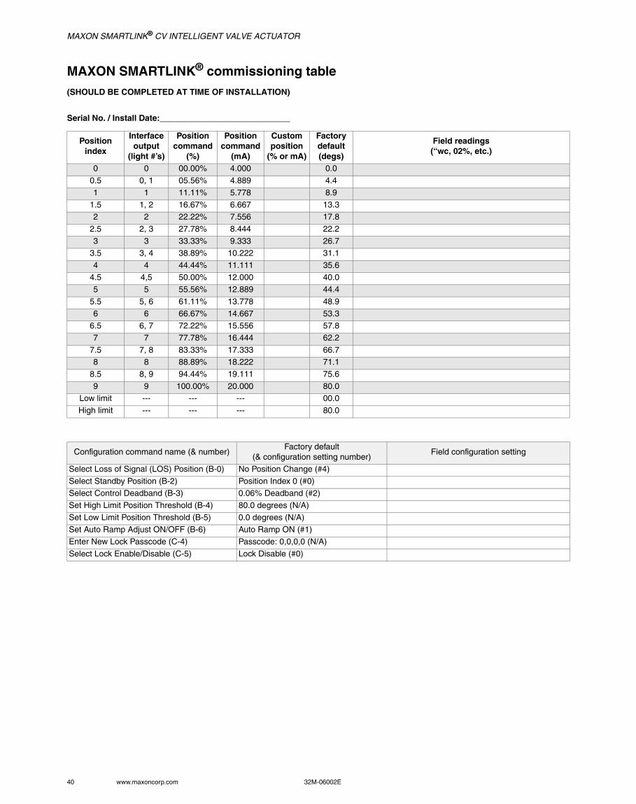
MAXON SMARTLINK® commissioning table (SHOULD BE COMPLETED AT TIME OF INSTALLATION)
Serial No. / Install Date:____________________________
Positionindex
Interfaceoutput
(light #’s)
Positioncommand
(%)
Positioncommand
(mA)
Customposition
(% or mA)
Factory default(degs)
Field readings(“wc, 02%, etc.)
0 0 00.00% 4.000 0.0
0.5 0, 1 05.56% 4.889 4.4
1 1 11.11% 5.778 8.9
1.5 1, 2 16.67% 6.667 13.32 2 22.22% 7.556 17.8
2.5 2, 3 27.78% 8.444 22.2
3 3 33.33% 9.333 26.73.5 3, 4 38.89% 10.222 31.1
4 4 44.44% 11.111 35.6
4.5 4,5 50.00% 12.000 40.05 5 55.56% 12.889 44.4
5.5 5, 6 61.11% 13.778 48.9
6 6 66.67% 14.667 53.36.5 6, 7 72.22% 15.556 57.8
7 7 77.78% 16.444 62.2
7.5 7, 8 83.33% 17.333 66.78 8 88.89% 18.222 71.1
8.5 8, 9 94.44% 19.111 75.6
9 9 100.00% 20.000 80.0Low limit --- --- --- 00.0
High limit --- --- --- 80.0
Configuration command name (& number)Factory default
(& configuration setting number)Field configuration setting
Select Loss of Signal (LOS) Position (B-0) No Position Change (#4)
Select Standby Position (B-2) Position Index 0 (#0)Select Control Deadband (B-3) 0.06% Deadband (#2)
Set High Limit Position Threshold (B-4) 80.0 degrees (N/A)
Set Low Limit Position Threshold (B-5) 0.0 degrees (N/A)Set Auto Ramp Adjust ON/OFF (B-6) Auto Ramp ON (#1)
Enter New Lock Passcode (C-4) Passcode: 0,0,0,0 (N/A)
Select Lock Enable/Disable (C-5) Lock Disable (#0)
MAXON SMARTLINK® CV INTELLIGENT VALVE ACTUATOR
32M-06002E 41
Unit locking and passcode entryThe SMARTLINK® Control Interface is shipped with the lock function disabled and a factory default 4-digit passcode or “combination” of 0,0,0,0. To lock the unit for the first time and change the default passcode, the lock function must first be enabled (Command C-5) and the default passcode entered (Command A-7) as described in the first two procedures below. After the lock function is enabled and the unit is “unlocked”, a new passcode can be entered using Command C-4 as described in the procedure below. If you forget the passcode, call MAXON for the “master” passcode.
ENABLING THE “LOCK” CONFIGURATION SETTING (COMMAND C-5):1. If the alarm light is blinking, the lock function is already enabled and the unit is in a “locked” state. Before changing the passcode, the
unit must be unlocked by entering the current passcode (Command A-7) using the procedure below.
2. If the alarm light is not blinking, select and enter Command C-5, Lock Enable/Disable. 3. After the command is entered, one of the numbered (0-9) lights will be on, indicating the current configuration setting. If the #1 light is
on, the lock function is already enabled and the procedure below can be performed to change the passcode. If the #0 light is on, the lock function is disabled.
4. To select the #1 setting (Lock Enable), momentarily push the INC/DEC switch in the up position. The #1 light will now be on, indicating the new setting is selected.
5. Push the ENTER button. The #1 light will turn off indicating the command is complete and the configuration setting is saved. The unit is now locked and the alarm light will be blinking.
6. To change the current passcode, perform the next two procedures (Command A-7 & C-4).
ENTERING THE CURRENT “LOCK” PASSCODE (COMMAND A-7):1. Select and enter Command A-7, Unlock Valve Configuration.
2. After the command is entered, the INC/DEC switch is used to select the first passcode digit. The digit selected is indicated by a num-bered light (0-9).
3. Once the first digit of the passcode is selected, push the ENTER button once. The numbered light should momentarily turn off indicat-ing the entry was accepted.
4. Repeat steps 2 and 3 for the 2nd, 3rd, and 4th passcode digits. If the passcode was entered incorrectly, all the numbered lights will momentarily flash after entry of the 4th and final passcode digit. If the passcode was correct, the alarm light will stop flashing and will be turned off completely if no other alarms exist.
5. To change the current passcode, perform the procedure (Command C-4) below.
ENTERING A NEW “LOCK” PASSCODE (COMMAND C-4):1. To enter a new lock passcode, the lock function must be enabled (Command C-5) and the current passcode must be entered (i.e. the
unit must be “unlocked” using Command A-7). See the two previous procedures if these command entry requirements have not been satisfied.
2. Select and enter Command C-4, Enter New Lock Combination.
3. After the command is entered, the INC/DEC switch is used to select the first new passcode digit. The digit selected is indicated by a numbered light (0-9).
4. Once the first new digit of the passcode is selected, push the ENTER button once. The numbered light should momentarily turn off indi-cating the entry was accepted. Write down the new digit for later use.
5. Repeat steps 3 and 4 for the 2nd, 3rd, and 4th passcode digits, remembering to write down each passcode digit as it is entered.
6. Verify the new passcode by re-locking the unit (MODE switch to the RUN position and then back to the middle, Command Entry posi-tion), and entering the new passcode using Command A-7 as described in the procedure above.
MAXON SMARTLINK® CV INTELLIGENT VALVE ACTUATOR
42 www.maxoncorp.com 32M-06002E
Manual operationCommand A-0, Enter Manual Positioning Mode, is used to override the 4-20 mA position command input. (This command should not be used when the valve is in an operating process that requires continuous positioning based on the 4-20 mA input signal.)
ENTERING MANUAL POSITIONING MODE (COMMAND A-0):1. To enter the Manual Positioning Mode, the position command input signal must be first driven to 4mA or less.
2. Select and enter Command A-0, Enter Manual Positioning Mode. If the numbered lights flash momentarily after entering Command A-0: a) the position command may not be less than 4 mA, b) the adjustment mode switch may be in the STANDBY position, or c) unit may be “locked” to prevent tampering.
3. After entering the command, the yellow manual (MAN) light will be on and RO5 (Relay Output driver #5) will energize the Manual Con-trol relay (if installed). The INC/DEC switch can be used to move the valve open or closed. If the adjustment mode switch is in the INDEX position, the INC/DEC switch is used to move between the 19 position “indexes”. If the adjustment mode switch is in the ADJ position, pushing the INC/DEC switch up or down changes the valve position in 1.0 degree steps. If the INC/DEC switch is held in the up or down position, the position is continuously adjusted until the maximum or minimum position is reached. When the max or min position setpoint is reached, all the numbered lights will momentarily flash.
This command should not be executed when the valve is part of an operating process that requires continuous, closed-loop valve positioning.
4. To return control back to the 4-20 mA position command input, move the MODE switch to the RUN position (down).
High and low valve position limitsThe high and low limits are automatically set when the user adjusts the maximum (Index #19) and minimum (Index #0) valve position settings. If different high and low limits are required (other than the default or automatically set limits), Command B-4 and Command B-5 can be executed using the procedure below.
Command B-4 is a configuration command that is used to adjust the high limit position threshold. Relay driver Output #3, RO3 will energize the optional High Position Limit relay when the valve position is equal to or greater than the stored high limit position threshold. The high limit threshold has a factory default of 80.0 degrees and is automatically set to 1.0 degree less than the maximum valve position when modified using Command A-2, Enter Position Setup Mode, or A-5, Set Max Position & Min/Max Ramp. If the factory default or automatic 1.0 degree offset is acceptable, execution of Command B-4 is not necessary.
Command B-5 is a configuration command that is used to adjust the low limit position threshold. Relay driver Output #4, RO4 will energize the optional Low Position Limit relay when the valve position is less than or equal to the stored low limit position threshold. The low limit threshold has a factory default of 0.0 degrees and is automatically set to 1.0 degree above the minimum valve position when modified using Command A-2, Enter Position Setup Mode, or A-6, Set Min Position & Min/Max Ramp. If the factory default or automatic 1.0 degree offset is acceptable, execution of Command B-5 is not necessary.
MANUALLY ADJUSTING THE HIGH OR LOW LIMIT POSITION THRESHOLD (COMMAND B-4 OR B-5):1. Before entering Command B-4 (or B-5), the unit must be in the Manual Positioning Mode (Execute Command A-0, as described on
page 42 or in Reference Table 8 on page 52).
2. With the unit in Manual Positioning Mode (as indicated by the yellow, MAN light on) and the ADJUST switch in the “ADJ” middle posi-tion, select and enter Command B-4 (or B-5). After command entry, the valve will be driven to the high (or low) limit position.
3. To change the valve position in +/- 1.0 degree steps, momentarily push the INC/DEC switch up or down. If the INC/DEC switch is held in the up or down position, the valve position setpoint is continuously changed in +/- 1.0 degree steps.
4. After moving the valve to the desired high (or low) limit position, push the ENTER button to save the new setting. When the ENTER but-ton is pressed, the numbered light(s) and command set “b” light will momentarily turn off, indicating the new value has been stored.
5. To return control back to the 4-20mA position command input, move the MODE switch to the RUN position (down). The unit is now in RUN mode.
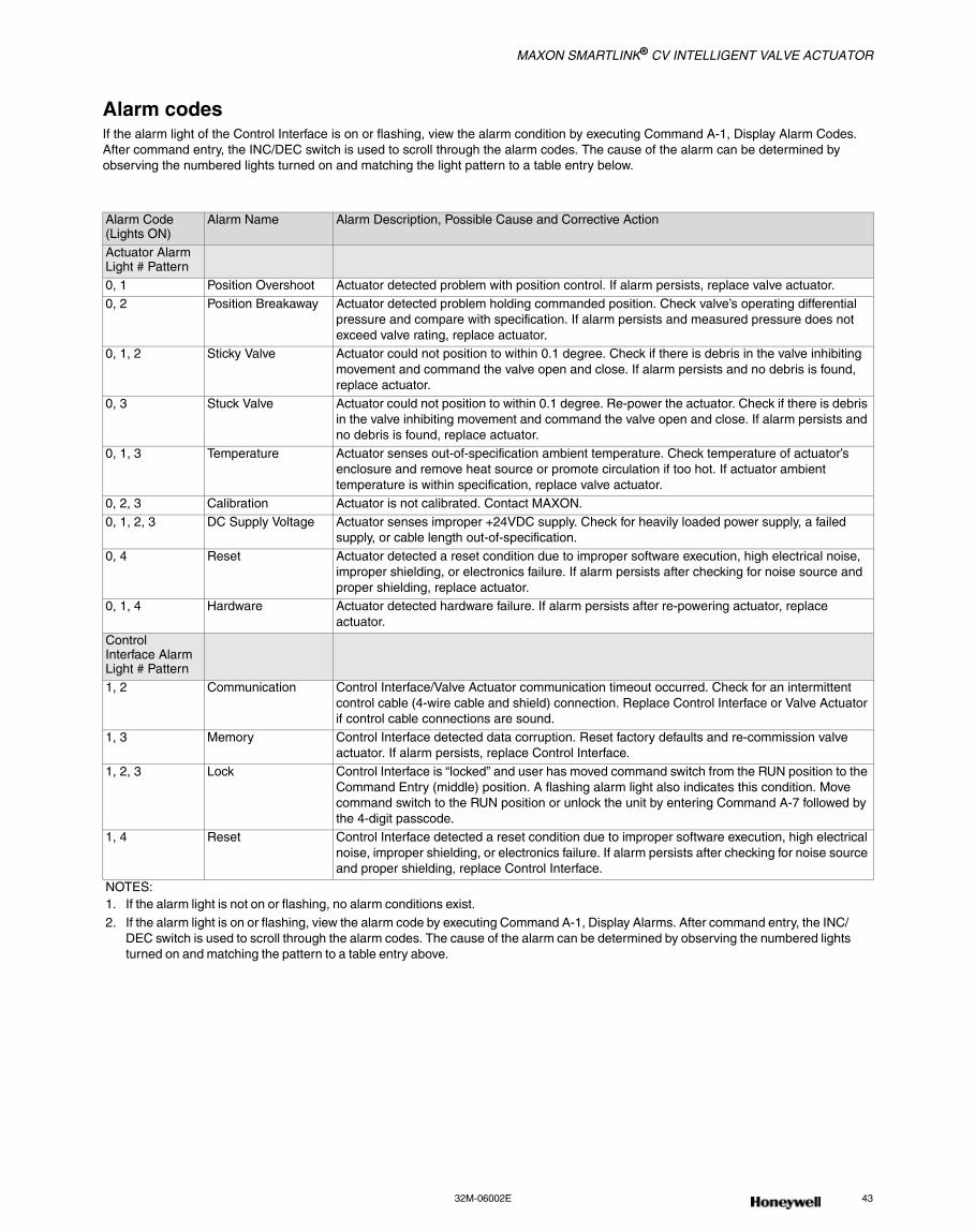
MAXON SMARTLINK® CV INTELLIGENT VALVE ACTUATOR
32M-06002E 43
Alarm codesIf the alarm light of the Control Interface is on or flashing, view the alarm condition by executing Command A-1, Display Alarm Codes. After command entry, the INC/DEC switch is used to scroll through the alarm codes. The cause of the alarm can be determined by observing the numbered lights turned on and matching the light pattern to a table entry below.
Alarm Code(Lights ON)
Alarm Name Alarm Description, Possible Cause and Corrective Action
Actuator AlarmLight # Pattern0, 1 Position Overshoot Actuator detected problem with position control. If alarm persists, replace valve actuator.
0, 2 Position Breakaway Actuator detected problem holding commanded position. Check valve’s operating differential pressure and compare with specification. If alarm persists and measured pressure does not exceed valve rating, replace actuator.
0, 1, 2 Sticky Valve Actuator could not position to within 0.1 degree. Check if there is debris in the valve inhibiting movement and command the valve open and close. If alarm persists and no debris is found, replace actuator.
0, 3 Stuck Valve Actuator could not position to within 0.1 degree. Re-power the actuator. Check if there is debris in the valve inhibiting movement and command the valve open and close. If alarm persists and no debris is found, replace actuator.
0, 1, 3 Temperature Actuator senses out-of-specification ambient temperature. Check temperature of actuator’s enclosure and remove heat source or promote circulation if too hot. If actuator ambient temperature is within specification, replace valve actuator.
0, 2, 3 Calibration Actuator is not calibrated. Contact MAXON.
0, 1, 2, 3 DC Supply Voltage Actuator senses improper +24VDC supply. Check for heavily loaded power supply, a failed supply, or cable length out-of-specification.
0, 4 Reset Actuator detected a reset condition due to improper software execution, high electrical noise, improper shielding, or electronics failure. If alarm persists after checking for noise source and proper shielding, replace actuator.
0, 1, 4 Hardware Actuator detected hardware failure. If alarm persists after re-powering actuator, replace actuator.
ControlInterface AlarmLight # Pattern1, 2 Communication Control Interface/Valve Actuator communication timeout occurred. Check for an intermittent
control cable (4-wire cable and shield) connection. Replace Control Interface or Valve Actuator if control cable connections are sound.
1, 3 Memory Control Interface detected data corruption. Reset factory defaults and re-commission valve actuator. If alarm persists, replace Control Interface.
1, 2, 3 Lock Control Interface is “locked” and user has moved command switch from the RUN position to the Command Entry (middle) position. A flashing alarm light also indicates this condition. Move command switch to the RUN position or unlock the unit by entering Command A-7 followed by the 4-digit passcode.
1, 4 Reset Control Interface detected a reset condition due to improper software execution, high electrical noise, improper shielding, or electronics failure. If alarm persists after checking for noise source and proper shielding, replace Control Interface.
NOTES:1. If the alarm light is not on or flashing, no alarm conditions exist.2. If the alarm light is on or flashing, view the alarm code by executing Command A-1, Display Alarms. After command entry, the INC/
DEC switch is used to scroll through the alarm codes. The cause of the alarm can be determined by observing the numbered lights turned on and matching the pattern to a table entry above.
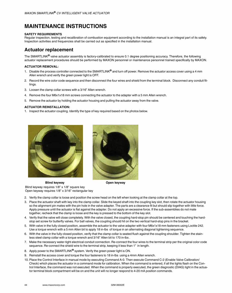
MAXON SMARTLINK® CV INTELLIGENT VALVE ACTUATOR
44 www.maxoncorp.com 32M-06002E
MAINTENANCE INSTRUCTIONSSAFETY REQUIREMENTSRegular inspection, testing and recalibration of combustion equipment according to the installation manual is an integral part of its safety. Inspection activities and frequencies shall be carried out as specified in the installation manual.
Actuator replacementThe SMARTLINK® valve actuator assembly is factory-calibrated to ensure 0.1 degree positioning accuracy. Therefore, the following actuator replacement procedures should be performed by MAXON personnel or maintenance personnel trained specifically by MAXON.
ACTUATOR REMOVAL:
1. Disable the process controller connected to the SMARTLINK® and turn off power. Remove the actuator access cover using a 4 mm Allen wrench and verify the green power light is OFF.
2. Record the wire color code sequence and then disconnect the four wires and shield from the terminal block. Disconnect any conduit fit-tings.
3. Loosen the clamp collar screws with a 3/16” Allen wrench.
4. Remove the four M6x1x18 mm screws connecting the actuator to the adapter with a 5 mm Allen wrench.
5. Remove the actuator by holding the actuator housing and pulling the actuator away from the valve.
ACTUATOR REINSTALLATION:1. Inspect the actuator coupling. Identify the type of key required based on the photos below.
2. Verify the clamp collar is loose and position the screw head on the left when looking at the clamp collar at the top.
3. Place the actuator shaft with key into the clamp collar. Slide the keyed shaft into the coupling key slot, then rotate the actuator housing so the alignment pin mates with the pin hole in the valve adapter. The parts are a clearance fit but should slip together with little force. Apply pressure until the actuator is flat against the adapter. Do not apply an excessive force. If the sub-assemblies do not mate together, recheck that the clamp is loose and the key is pressed to the bottom of the key slot.
4. Verify that the valve will close completely. With the valve closed, the coupling hard-stop pin should be centered and touching the hard-stop set screw for butterfly valves. For ball valves, the coupling should hit on the two vertical hard-stop pins in the bracket.
5. With valve in the fully closed position, assemble the actuator to the valve adapter with four M6x1x18 mm fasteners using Loctite 242. Use a torque wrench with a 5 mm Allen bit to apply 18 in-lbs of torque in an alternating diagonal tightening sequence.
6. With the valve in the fully closed position, verify that the clamp collar is seated flush against the coupling shoulder. Tighten the stain-less steel clamp collar with a torque wrench and 3/16” Allen bit to 170 in-lbs .
7. Make the necessary water-tight electrical conduit connection. Re-connect the four wires to the terminal strip per the original color code sequence. Re-connect the shield wire to the terminal strip, keeping it less than 1” in length.
8. Apply power to the SMARTLINK® system. Verify the green power light is ON.9. Reinstall the access cover and torque the four fasteners to 18 in-lbs using a 4mm Allen wrench.
10. Place the Control Interface in manual mode by executing Command A-0. Then execute Command C-2 (Enable Valve Calibration/Check) which places the actuator in a command mode for calibration. When the command is entered, if all the lights flash on the Con-trol Interface, the command was not executed. When the command is properly executed, the green diagnostic (DIAG) light in the actua-tor terminal block compartment will be on and the unit will no longer respond to 4-20 mA position commands.
Blind keyway Open keywayBlind keyway requires 1/8” x 1/8” square keyOpen keyway requires 1/8” x 3/16” rectangular key
MAXON SMARTLINK® CV INTELLIGENT VALVE ACTUATOR
32M-06002E 45
11. Execute Command C-1 (Calibrate Valve) which closes the valve until the hard-stop is found, establishes a new home (or 0 degree) position, and moves the valve through all 800 positions. The command takes 2 or 3 minutes to execute during which half of the num-bered lights on the Control Interface flash on and off. When the command is finished, the Control Interface will flash all of the num-bered lights ON if the command was not successful. If the calibration failed, repeat the command a second time.
12. Execute Command C-0 to check the new calibration. This command takes less than 90 seconds and will flash half of the numbered lights during execution. At the end of command execution, if all the number lights on the Control Interface flash ON and then OFF, the calibration test failed. Re-mount the valve to the assembly as described above and repeat the calibration procedure. If the calibration test passed, cycle power to the actuator and check for a calibration alarm. (The actuator’s green diagnostic light should now be flash-ing and the alarm light on the Control Interface should be off.)
13. Re-enable the process controller commanding SMARTLINK®.
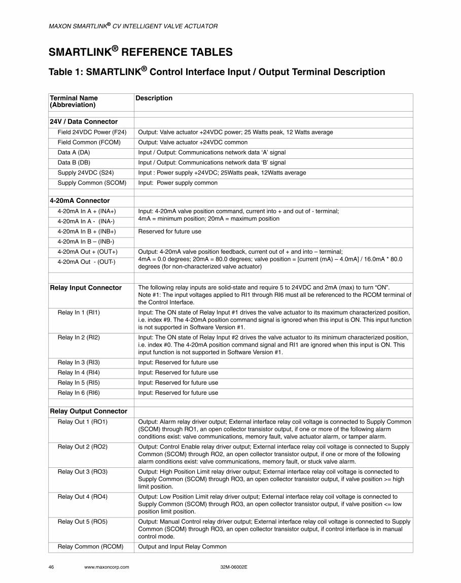
MAXON SMARTLINK® CV INTELLIGENT VALVE ACTUATOR
46 www.maxoncorp.com 32M-06002E
SMARTLINK® REFERENCE TABLES
Table 1: SMARTLINK® Control Interface Input / Output Terminal Description
Terminal Name (Abbreviation)
Description
24V / Data Connector
Field 24VDC Power (F24) Output: Valve actuator +24VDC power; 25 Watts peak, 12 Watts average
Field Common (FCOM) Output: Valve actuator +24VDC common
Data A (DA) Input / Output: Communications network data ‘A’ signal
Data B (DB) Input / Output: Communications network data ‘B’ signal
Supply 24VDC (S24) Input : Power supply +24VDC; 25Watts peak, 12Watts average
Supply Common (SCOM) Input: Power supply common
4-20mA Connector
4-20mA In A + (INA+) Input: 4-20mA valve position command, current into + and out of - terminal;4mA = minimum position; 20mA = maximum position 4-20mA In A - (INA-)
4-20mA In B + (INB+) Reserved for future use
4-20mA In B – (INB-)
4-20mA Out + (OUT+) Output: 4-20mA valve position feedback, current out of + and into – terminal;4mA = 0.0 degrees; 20mA = 80.0 degrees; valve position = [current (mA) – 4.0mA] / 16.0mA * 80.0 degrees (for non-characterized valve actuator)
4-20mA Out - (OUT-)
Relay Input Connector The following relay inputs are solid-state and require 5 to 24VDC and 2mA (max) to turn “ON”.Note #1: The input voltages applied to RI1 through RI6 must all be referenced to the RCOM terminal of the Control Interface.
Relay In 1 (RI1) Input: The ON state of Relay Input #1 drives the valve actuator to its maximum characterized position, i.e. index #9. The 4-20mA position command signal is ignored when this input is ON. This input function is not supported in Software Version #1.
Relay In 2 (RI2) Input: The ON state of Relay Input #2 drives the valve actuator to its minimum characterized position, i.e. index #0. The 4-20mA position command signal and RI1 are ignored when this input is ON. This input function is not supported in Software Version #1.
Relay In 3 (RI3) Input: Reserved for future use
Relay In 4 (RI4) Input: Reserved for future use
Relay In 5 (RI5) Input: Reserved for future use
Relay In 6 (RI6) Input: Reserved for future use
Relay Output Connector
Relay Out 1 (RO1) Output: Alarm relay driver output; External interface relay coil voltage is connected to Supply Common (SCOM) through RO1, an open collector transistor output, if one or more of the following alarm conditions exist: valve communications, memory fault, valve actuator alarm, or tamper alarm.
Relay Out 2 (RO2) Output: Control Enable relay driver output; External interface relay coil voltage is connected to Supply Common (SCOM) through RO2, an open collector transistor output, if one or more of the following alarm conditions exist: valve communications, memory fault, or stuck valve alarm.
Relay Out 3 (RO3) Output: High Position Limit relay driver output; External interface relay coil voltage is connected to Supply Common (SCOM) through RO3, an open collector transistor output, if valve position >= high limit position.
Relay Out 4 (RO4) Output: Low Position Limit relay driver output; External interface relay coil voltage is connected to Supply Common (SCOM) through RO3, an open collector transistor output, if valve position <= low position limit position.
Relay Out 5 (RO5) Output: Manual Control relay driver output; External interface relay coil voltage is connected to Supply Common (SCOM) through RO3, an open collector transistor output, if control interface is in manual control mode.
Relay Common (RCOM) Output and Input Relay Common
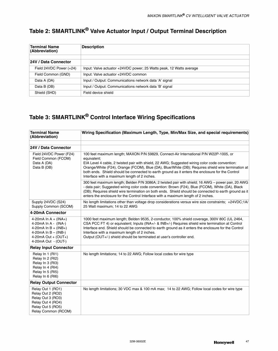
MAXON SMARTLINK® CV INTELLIGENT VALVE ACTUATOR
32M-06002E 47
Table 2: SMARTLINK® Valve Actuator Input / Output Terminal Description
Table 3: SMARTLINK® Control Interface Wiring Specifications
Terminal Name (Abbreviation)
Description
24V / Data Connector
Field 24VDC Power (+24) Input: Valve actuator +24VDC power; 25 Watts peak, 12 Watts average
Field Common (GND) Input: Valve actuator +24VDC common
Data A (DA) Input / Output: Communications network data ‘A’ signal
Data B (DB) Input / Output: Communications network data ‘B’ signal
Shield (SHD) Field device shield
Terminal Name (Abbreviation)
Wiring Specification (Maximum Length, Type, Min/Max Size, and special requirements)
24V / Data Connector
Field 24VDC Power (F24) Field Common (FCOM) Data A (DA) Data B (DB)
100 feet maximum length; MAXON P/N 59829, Connect-Air International P/N W22P-1005, or equivalent;EIA Level 4 cable, 2 twisted pair with shield, 22 AWG; Suggested wiring color code convention: Orange/White (F24), Orange (FCOM), Blue (DA), Blue/White (DB); Requires shield wire termination at both ends. Shield should be connected to earth ground as it enters the enclosure for the Control Interface with a maximum length of 2 inches.
300 feet maximum length; Belden P/N 3086A; 2 twisted pair with shield; 16 AWG – power pair, 20 AWG - data pair; Suggested wiring color code convention: Brown (F24), Blue (FCOM), White (DA), Black (DB); Requires shield wire termination on both ends. Shield should be connected to earth ground as it enters the enclosure for the Control Interface with a maximum length of 2 inches.
Supply 24VDC (S24)Supply Common (SCOM)
No length limitations other than voltage drop considerations versus wire size constraints; +24VDC;1A/25 Watt maximum; 14 to 22 AWG
4-20mA Connector
4-20mA In A + (INA+)4-20mA In A - (INA-)4-20mA In B + (INB+)4-20mA In B – (INB-)4-20mA Out + (OUT+)4-20mA Out - (OUT-)
1000 feet maximum length; Belden 9535, 2-conductor, 100% shield coverage, 300V 80C (UL 2464, CSA PCC FT 4) or equivalent; Inputs (INA+/- & INB+/-) Requires shield wire termination at Control Interface end. Shield should be connected to earth ground as it enters the enclosure for the Control Interface with a maximum length of 2 inches.Output (OUT+/-) shield should be terminated at user’s controller end.
Relay Input Connector
Relay In 1 (RI1) Relay In 2 (RI2) Relay In 3 (RI3) Relay In 4 (RI4) Relay In 5 (RI5) Relay In 6 (RI6)
No length limitations; 14 to 22 AWG; Follow local codes for wire type
Relay Output Connector
Relay Out 1 (RO1)Relay Out 2 (RO2)Relay Out 3 (RO3)Relay Out 4 (RO4)Relay Out 5 (RO5)Relay Common (RCOM)
No length limitations; 30 VDC max & 100 mA max; 14 to 22 AWG; Follow local codes for wire type
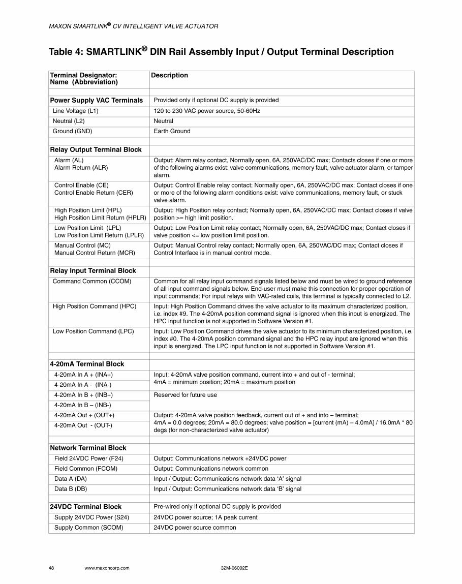
MAXON SMARTLINK® CV INTELLIGENT VALVE ACTUATOR
48 www.maxoncorp.com 32M-06002E
Table 4: SMARTLINK® DIN Rail Assembly Input / Output Terminal Description
Terminal Designator: Name (Abbreviation)
Description
Power Supply VAC Terminals Provided only if optional DC supply is provided
Line Voltage (L1) 120 to 230 VAC power source, 50-60Hz
Neutral (L2) Neutral
Ground (GND) Earth Ground
Relay Output Terminal Block
Alarm (AL) Alarm Return (ALR)
Output: Alarm relay contact, Normally open, 6A, 250VAC/DC max; Contacts closes if one or more of the following alarms exist: valve communications, memory fault, valve actuator alarm, or tamper alarm.
Control Enable (CE) Control Enable Return (CER)
Output: Control Enable relay contact; Normally open, 6A, 250VAC/DC max; Contact closes if one or more of the following alarm conditions exist: valve communications, memory fault, or stuck valve alarm.
High Position Limit (HPL) High Position Limit Return (HPLR)
Output: High Position relay contact; Normally open, 6A, 250VAC/DC max; Contact closes if valve position >= high limit position.
Low Position Limit (LPL) Low Position Limit Return (LPLR)
Output: Low Position Limit relay contact; Normally open, 6A, 250VAC/DC max; Contact closes if valve position <= low position limit position.
Manual Control (MC) Manual Control Return (MCR)
Output: Manual Control relay contact; Normally open, 6A, 250VAC/DC max; Contact closes if Control Interface is in manual control mode.
Relay Input Terminal Block
Command Common (CCOM) Common for all relay input command signals listed below and must be wired to ground reference of all input command signals below. End-user must make this connection for proper operation of input commands; For input relays with VAC-rated coils, this terminal is typically connected to L2.
High Position Command (HPC) Input: High Position Command drives the valve actuator to its maximum characterized position, i.e. index #9. The 4-20mA position command signal is ignored when this input is energized. The HPC input function is not supported in Software Version #1.
Low Position Command (LPC) Input: Low Position Command drives the valve actuator to its minimum characterized position, i.e. index #0. The 4-20mA position command signal and the HPC relay input are ignored when this input is energized. The LPC input function is not supported in Software Version #1.
4-20mA Terminal Block
4-20mA In A + (INA+) Input: 4-20mA valve position command, current into + and out of - terminal;4mA = minimum position; 20mA = maximum position 4-20mA In A - (INA-)
4-20mA In B + (INB+) Reserved for future use
4-20mA In B – (INB-)
4-20mA Out + (OUT+) Output: 4-20mA valve position feedback, current out of + and into – terminal;4mA = 0.0 degrees; 20mA = 80.0 degrees; valve position = [current (mA) – 4.0mA] / 16.0mA * 80 degs (for non-characterized valve actuator)
4-20mA Out - (OUT-)
Network Terminal Block
Field 24VDC Power (F24) Output: Communications network +24VDC power
Field Common (FCOM) Output: Communications network common
Data A (DA) Input / Output: Communications network data ‘A’ signal
Data B (DB) Input / Output: Communications network data ‘B’ signal
24VDC Terminal Block Pre-wired only if optional DC supply is provided
Supply 24VDC Power (S24) 24VDC power source; 1A peak current
Supply Common (SCOM) 24VDC power source common
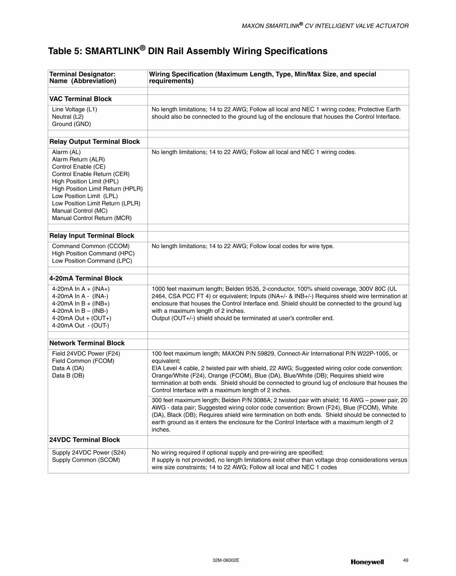
MAXON SMARTLINK® CV INTELLIGENT VALVE ACTUATOR
32M-06002E 49
Table 5: SMARTLINK® DIN Rail Assembly Wiring Specifications
Terminal Designator: Name (Abbreviation)
Wiring Specification (Maximum Length, Type, Min/Max Size, and special requirements)
VAC Terminal Block
Line Voltage (L1)Neutral (L2)Ground (GND)
No length limitations; 14 to 22 AWG; Follow all local and NEC 1 wiring codes; Protective Earth should also be connected to the ground lug of the enclosure that houses the Control Interface.
Relay Output Terminal Block
Alarm (AL)Alarm Return (ALR)Control Enable (CE)Control Enable Return (CER)High Position Limit (HPL)High Position Limit Return (HPLR)Low Position Limit (LPL)Low Position Limit Return (LPLR)Manual Control (MC) Manual Control Return (MCR)
No length limitations; 14 to 22 AWG; Follow all local and NEC 1 wiring codes.
Relay Input Terminal Block
Command Common (CCOM)High Position Command (HPC)Low Position Command (LPC)
No length limitations; 14 to 22 AWG; Follow local codes for wire type.
4-20mA Terminal Block
4-20mA In A + (INA+)4-20mA In A - (INA-)4-20mA In B + (INB+)4-20mA In B – (INB-)4-20mA Out + (OUT+)4-20mA Out - (OUT-)
1000 feet maximum length; Belden 9535, 2-conductor, 100% shield coverage, 300V 80C (UL 2464, CSA PCC FT 4) or equivalent; Inputs (INA+/- & INB+/-) Requires shield wire termination at enclosure that houses the Control Interface end. Shield should be connected to the ground lug with a maximum length of 2 inches.Output (OUT+/-) shield should be terminated at user’s controller end.
Network Terminal Block
Field 24VDC Power (F24)Field Common (FCOM)Data A (DA)Data B (DB)
100 feet maximum length; MAXON P/N 59829, Connect-Air International P/N W22P-1005, or equivalent;EIA Level 4 cable, 2 twisted pair with shield, 22 AWG; Suggested wiring color code convention: Orange/White (F24), Orange (FCOM), Blue (DA), Blue/White (DB); Requires shield wire termination at both ends. Shield should be connected to ground lug of enclosure that houses the Control Interface with a maximum length of 2 inches.
300 feet maximum length; Belden P/N 3086A; 2 twisted pair with shield; 16 AWG – power pair, 20 AWG - data pair; Suggested wiring color code convention: Brown (F24), Blue (FCOM), White (DA), Black (DB); Requires shield wire termination on both ends. Shield should be connected to earth ground as it enters the enclosure for the Control Interface with a maximum length of 2 inches.
24VDC Terminal Block
Supply 24VDC Power (S24)Supply Common (SCOM)
No wiring required if optional supply and pre-wiring are specified; If supply is not provided, no length limitations exist other than voltage drop considerations versus wire size constraints; 14 to 22 AWG; Follow all local and NEC 1 codes
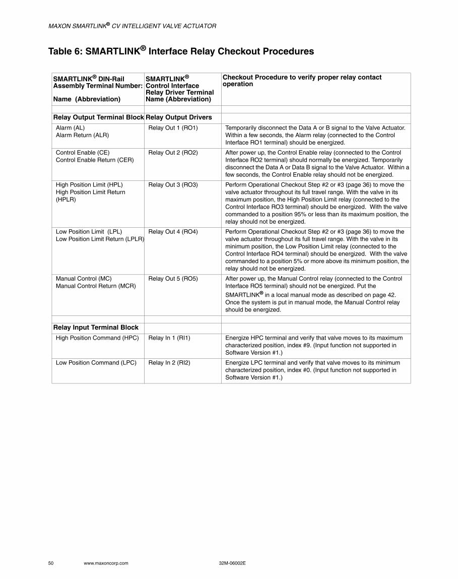
MAXON SMARTLINK® CV INTELLIGENT VALVE ACTUATOR
50 www.maxoncorp.com 32M-06002E
Table 6: SMARTLINK® Interface Relay Checkout Procedures
SMARTLINK® DIN-Rail Assembly Terminal Number:
Name (Abbreviation)
SMARTLINK®
Control InterfaceRelay Driver TerminalName (Abbreviation)
Checkout Procedure to verify proper relay contact operation
Relay Output Terminal Block Relay Output Drivers
Alarm (AL)Alarm Return (ALR)
Relay Out 1 (RO1) Temporarily disconnect the Data A or B signal to the Valve Actuator. Within a few seconds, the Alarm relay (connected to the Control Interface RO1 terminal) should be energized.
Control Enable (CE)Control Enable Return (CER)
Relay Out 2 (RO2) After power up, the Control Enable relay (connected to the Control Interface RO2 terminal) should normally be energized. Temporarily disconnect the Data A or Data B signal to the Valve Actuator. Within a few seconds, the Control Enable relay should not be energized.
High Position Limit (HPL)High Position Limit Return (HPLR)
Relay Out 3 (RO3) Perform Operational Checkout Step #2 or #3 (page 36) to move the valve actuator throughout its full travel range. With the valve in its maximum position, the High Position Limit relay (connected to the Control Interface RO3 terminal) should be energized. With the valve commanded to a position 95% or less than its maximum position, the relay should not be energized.
Low Position Limit (LPL)Low Position Limit Return (LPLR)
Relay Out 4 (RO4) Perform Operational Checkout Step #2 or #3 (page 36) to move the valve actuator throughout its full travel range. With the valve in its minimum position, the Low Position Limit relay (connected to the Control Interface RO4 terminal) should be energized. With the valve commanded to a position 5% or more above its minimum position, the relay should not be energized.
Manual Control (MC) Manual Control Return (MCR)
Relay Out 5 (RO5) After power up, the Manual Control relay (connected to the Control Interface RO5 terminal) should not be energized. Put the
SMARTLINK® in a local manual mode as described on page 42. Once the system is put in manual mode, the Manual Control relay should be energized.
Relay Input Terminal Block
High Position Command (HPC) Relay In 1 (RI1) Energize HPC terminal and verify that valve moves to its maximum characterized position, index #9. (Input function not supported in Software Version #1.)
Low Position Command (LPC) Relay In 2 (RI2) Energize LPC terminal and verify that valve moves to its minimum characterized position, index #0. (Input function not supported in Software Version #1.)
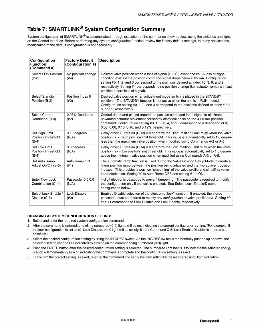
MAXON SMARTLINK® CV INTELLIGENT VALVE ACTUATOR
32M-06002E 51
Table 7: SMARTLINK® System Configuration SummarySystem configuration of SMARTLINK® is accomplished through execution of the commands shown below, using the switches and lights on the Control Interface. Before performing any system configuration function, review the factory default settings. In many applications, modification of the default configuration is not necessary.
CHANGING A SYSTEM CONFIGURATION SETTING:1. Select and enter the required system configuration command.2. After the command is entered, one of the numbered (0-9) lights will be on, indicating the current configuration setting. (For example: If
the lock configuration is set to #0, Lock Disable, the 0 light will be solidly lit after Command C-5, Lock Enable/Disable, is entered suc-cessfully.)
3. Select the desired configuration setting by using the INC/DEC switch. As the INC/DEC switch is momentarily pushed up or down, the selected setting changes as indicated by turning on the corresponding numbered (0-9) light.
4. Push the ENTER button after the desired configuration setting is selected. The numbered light that is lit to indicate the selected config-uration will momentarily turn off indicating the command is complete and the configuration setting is saved.
5. To confirm the correct setting is saved, re-enter the command and verify the new setting by the numbered (0-9) light indication.
ConfigurationFunction (Command #)
Factory Default(Configuration #)
Description
Select LOS Position (B-0)
No position change (#4)
Desired valve position when a loss of signal (L.O.S.) event occurs. A loss of signal condition exists if the position command signal drops below 0.05 mA. Configuration setting #0, 1, 2, and 3 correspond to the positions defined at index #0, 3, 6, and 9, respectively. Setting #4 corresponds to no position change (i.e. actuator remains in last position before loss of signal).
Select Standby Position (B-2)
Position Index 0(#0)
Desired valve position when adjustment mode switch is placed in the STANDBY position. (The STANDBY function is not active when the unit is in RUN mode.) Configuration setting #0, 1, 2, and 3 correspond to the positions defined at index #0, 3, 6, and 9, respectively.
Select Control Deadband (B-3)
0.06% Deadband(#2)
Control deadband placed around the position command input signal to eliminate unwanted actuator movement caused by electrical noise on the 4-20 mA position command. Configuration setting #0, 1, 2, 3, 4, and 5 correspond to a deadband of 0, 0.03, 0.06, 0.13, 0.16, and 0.19%, respectively.
Set High Limit Position Threshold (B-4)
80.0 degrees(N/A)
Relay driver Output #3 (RO3) will energize the High Position Limit relay when the valve position is >= high position limit threshold. This value is automatically set to 1.0 degree less than the maximum valve position when modified using Commands A-2 or A-5.
Set Low Limit Position Threshold (B-5)
0.0 degrees(N/A)
Relay driver Output #4 (RO4) will energize the Low Position Limit relay when the valve position is <= low position limit threshold. This value is automatically set to 1.0 degree above the minimum valve position when modified using Commands A-2 or A-6.
Set Auto Ramp Adjust On/Off (B-6)
Auto Ramp ON(#1)
The automatic ramp function is used during the Valve Position Setup Mode to create a linear position ramp between the position being adjusted and the two adjacent position indexes. This provides a position “smoothing” of the valve profile and simplifies valve characterization. Setting #0 is Auto Ramp OFF and setting #1 is ON.
Enter New Lock Combination (C-4)
Passcode: 0,0,0,0(N/A)
4-digit electronic passcode to prevent tampering. The passcode is required to modify the configuration only if the lock is enabled. See Select Lock Enable/Disable configuration below.
Select Lock Enable / Disable (C-5)
Lock Disable(#0)
Enable / Disable selection of the electronic “lock” function. If enabled, the stored passcode must be entered to modify any configuration or valve profile data. Setting #0 and #1 correspond to Lock Disable and Lock Enable, respectively.
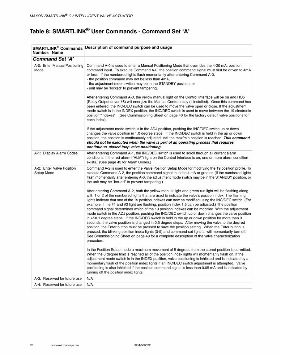
MAXON SMARTLINK® CV INTELLIGENT VALVE ACTUATOR
52 www.maxoncorp.com 32M-06002E
Table 8: SMARTLINK® User Commands - Command Set ‘A’
SMARTLINK® Commands Number: Name
Description of command purpose and usage
Command Set ‘A’A-0: Enter Manual Positioning Mode
Command A-0 is used to enter a Manual Positioning Mode that overrides the 4-20 mA, position command input. To execute Command A-0, the position command signal must first be driven to 4mA or less. If the numbered lights flash momentarily after entering Command A-0, - the position command may not be less than 4mA, - the adjustment mode switch may be in the STANDBY position, or - unit may be “locked” to prevent tampering.
After entering Command A-0, the yellow manual light on the Control Interface will be on and RO5 (Relay Output driver #5) will energize the Manual Control relay (if installed). Once this command has been entered, the INC/DEC switch can be used to move the valve open or close. If the adjustment mode switch is in the INDEX position, the INC/DEC switch is used to move between the 19 electronic position “indexes”. (See Commissioning Sheet on page 40 for the factory default valve positions for each index).
If the adjustment mode switch is in the ADJ position, pushing the INC/DEC switch up or down changes the valve position in 1.0 degree steps. If the INC/DEC switch is held in the up or down position, the position is continuously adjusted until the max/min position is reached. This command should not be executed when the valve is part of an operating process that requires continuous, closed-loop valve positioning.
A-1: Display Alarm Codes After entering Command A-1, the INC/DEC switch is used to scroll through all current alarm conditions. If the red alarm (“ALM”) light on the Control Interface is on, one or more alarm condition exists. (See page 43 for Alarm Codes.)
A-2: Enter Valve Position Setup Mode
Command A-2 is used to enter the Valve Position Setup Mode for modifying the 19 position profile. To execute Command A-2, the position command signal must be 4 mA or greater. (If the numbered lights flash momentarily after entering A-0, the adjustment mode switch may be in the STANDBY position, or the unit may be “locked” to prevent tampering.)
After entering Command A-2, both the yellow manual light and green run light will be flashing along with 1 or 2 of the numbered lights that are used to indicate the valve’s position index. The flashing lights indicate that one of the 19 position indexes can now be modified using the INC/DEC switch. (For example, if the #1 and #2 light are flashing, position index 1.5 can be adjusted.) The position command signal determines which of the 19 position indexes can be modified. With the adjustment mode switch in the ADJ position, pushing the INC/DEC switch up or down changes the valve position in +/-0.1 degree steps. If the INC/DEC switch is held in the up or down position for more than 3 seconds, the valve position is changed in 0.5 degree steps. After moving the valve to the desired position, the Enter button must be pressed to save the position setting. When the Enter button is pressed, the blinking position index lights (0-9) and command set light ‘a’ will momentarily turn off. See Commissioning Sheet on page 40 for a complete description of the valve characterization procedure.
In the Position Setup mode a maximum movement of 8 degrees from the stored position is permitted. When the 8 degree limit is reached all of the position index lights will momentarily flash on. If the adjustment mode switch is in the INDEX position, valve positioning is inhibited and is indicated by a momentary flash of the position index lights if an INC/DEC switch adjustment is attempted. Valve positioning is also inhibited if the position command signal is less than 0.05 mA and is indicated by turning off the position index lights.
A-3: Reserved for future use N/A
A-4: Reserved for future use N/A
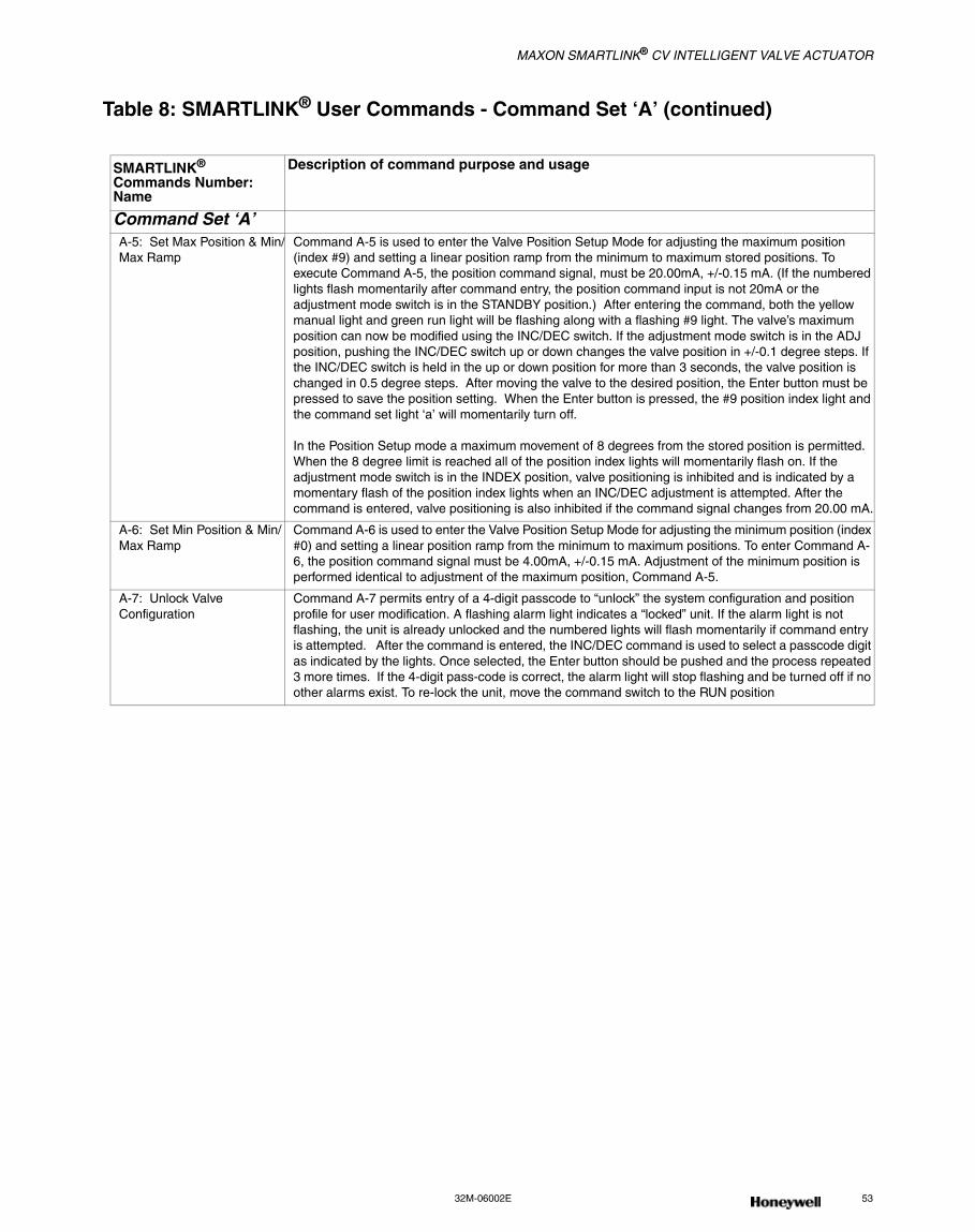
MAXON SMARTLINK® CV INTELLIGENT VALVE ACTUATOR
32M-06002E 53
Table 8: SMARTLINK® User Commands - Command Set ‘A’ (continued)
SMARTLINK® Commands Number: Name
Description of command purpose and usage
Command Set ‘A’A-5: Set Max Position & Min/Max Ramp
Command A-5 is used to enter the Valve Position Setup Mode for adjusting the maximum position (index #9) and setting a linear position ramp from the minimum to maximum stored positions. To execute Command A-5, the position command signal, must be 20.00mA, +/-0.15 mA. (If the numbered lights flash momentarily after command entry, the position command input is not 20mA or the adjustment mode switch is in the STANDBY position.) After entering the command, both the yellow manual light and green run light will be flashing along with a flashing #9 light. The valve’s maximum position can now be modified using the INC/DEC switch. If the adjustment mode switch is in the ADJ position, pushing the INC/DEC switch up or down changes the valve position in +/-0.1 degree steps. If the INC/DEC switch is held in the up or down position for more than 3 seconds, the valve position is changed in 0.5 degree steps. After moving the valve to the desired position, the Enter button must be pressed to save the position setting. When the Enter button is pressed, the #9 position index light and the command set light ‘a’ will momentarily turn off.
In the Position Setup mode a maximum movement of 8 degrees from the stored position is permitted. When the 8 degree limit is reached all of the position index lights will momentarily flash on. If the adjustment mode switch is in the INDEX position, valve positioning is inhibited and is indicated by a momentary flash of the position index lights when an INC/DEC adjustment is attempted. After the command is entered, valve positioning is also inhibited if the command signal changes from 20.00 mA.
A-6: Set Min Position & Min/Max Ramp
Command A-6 is used to enter the Valve Position Setup Mode for adjusting the minimum position (index #0) and setting a linear position ramp from the minimum to maximum positions. To enter Command A-6, the position command signal must be 4.00mA, +/-0.15 mA. Adjustment of the minimum position is performed identical to adjustment of the maximum position, Command A-5.
A-7: Unlock Valve Configuration
Command A-7 permits entry of a 4-digit passcode to “unlock” the system configuration and position profile for user modification. A flashing alarm light indicates a “locked” unit. If the alarm light is not flashing, the unit is already unlocked and the numbered lights will flash momentarily if command entry is attempted. After the command is entered, the INC/DEC command is used to select a passcode digit as indicated by the lights. Once selected, the Enter button should be pushed and the process repeated 3 more times. If the 4-digit pass-code is correct, the alarm light will stop flashing and be turned off if no other alarms exist. To re-lock the unit, move the command switch to the RUN position
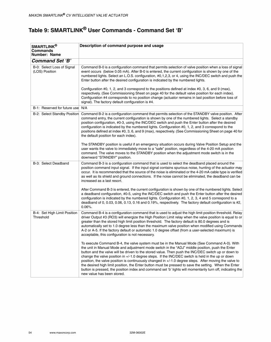
MAXON SMARTLINK® CV INTELLIGENT VALVE ACTUATOR
54 www.maxoncorp.com 32M-06002E
Table 9: SMARTLINK® User Commands - Command Set ‘B’
SMARTLINK® CommandsNumber: Name
Description of command purpose and usage
Command Set ‘B’B-0: Select Loss of Signal (LOS) Position
Command B-0 is a configuration command that permits selection of valve position when a loss of signal event occurs (below 0.05 mA). After B-0 is entered, the current configuration is shown by one of the numbered lights. Select an L.O.S. configuration, #0,1,2,3, or 4, using the INC/DEC switch and push the Enter button after the desired configuration is indicated by the numbered lights.
Configuration #0, 1, 2, and 3 correspond to the positions defined at index #0, 3, 6, and 9 (max), respectively. (See Commissioning Sheet on page 40 for the default valve position for each index). Configuration #4 corresponds to no position change (actuator remains in last position before loss of signal). The factory default configuration is #4.
B-1: Reserved for future use N/A
B-2: Select Standby Position Command B-2 is a configuration command that permits selection of the STANDBY valve position. After command entry, the current configuration is shown by one of the numbered lights. Select a standby position configuration, #0-3, using the INC/DEC switch and push the Enter button after the desired configuration is indicated by the numbered lights. Configuration #0, 1, 2, and 3 correspond to the positions defined at index #0, 3, 6, and 9 (max), respectively. (See Commissioning Sheet on page 40 for the default position for each index).
The STANDBY position is useful if an emergency situation occurs during Valve Position Setup and the user wants the valve to immediately move to a “safe” position, regardless of the 4-20 mA position command. The valve moves to the STANDBY position when the adjustment mode switch is in the downward “STANDBY” position.
B-3: Select Deadband Command B-3 is a configuration command that is used to select the deadband placed around the position command input signal. If the input signal contains spurious noise, hunting of the actuator may occur. It is recommended that the source of the noise is eliminated or the 4-20 mA cable type is verified as well as its shield and ground connections. If the noise cannot be eliminated, the deadband can be increased as a last resort.
After Command B-3 is entered, the current configuration is shown by one of the numbered lights. Select a deadband configuration, #0-5, using the INC/DEC switch and push the Enter button after the desired configuration is indicated by the numbered lights. Configuration #0, 1, 2, 3, 4 and 5 correspond to a deadband of 0, 0.03, 0.06, 0.13, 0.16 and 0.19%, respectively. The factory default configuration is #2, 0.06%.
B-4: Set High Limit Position Threshold
Command B-4 is a configuration command that is used to adjust the high limit position threshold. Relay driver Output #3 (RO3) will energize the High Position Limit relay when the valve position is equal to or greater than the stored high limit position threshold. The factory default is 80.0 degrees and is automatically set to 1.0 degree less than the maximum valve position when modified using Commands A-2 or A-5. If the factory default or automatic 1.0 degree offset (from a user-selected maximum) is acceptable, this configuration is not necessary.
To execute Command B-4, the valve system must be in the Manual Mode (See Command A-0). With the unit in Manual Mode and adjustment mode switch in the “ADJ” middle position, push the Enter button and the valve will be driven to the stored value. Then push the INC/DEC switch up or down to change the valve position in +/-1.0 degree steps. If the INC/DEC switch is held in the up or down position, the valve position is continuously changed in +/-1.0 degree steps. After moving the valve to the desired high limit position, the Enter button must be pressed to save the setting. When the Enter button is pressed, the position index and command set ‘b’ lights will momentarily turn off, indicating the new value has been stored.
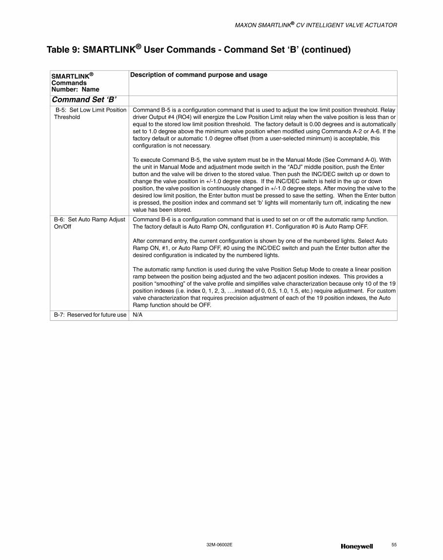
MAXON SMARTLINK® CV INTELLIGENT VALVE ACTUATOR
32M-06002E 55
Table 9: SMARTLINK® User Commands - Command Set ‘B’ (continued)
SMARTLINK® CommandsNumber: Name
Description of command purpose and usage
Command Set ‘B’ B-5: Set Low Limit Position Threshold
Command B-5 is a configuration command that is used to adjust the low limit position threshold. Relay driver Output #4 (RO4) will energize the Low Position Limit relay when the valve position is less than or equal to the stored low limit position threshold. The factory default is 0.00 degrees and is automatically set to 1.0 degree above the minimum valve position when modified using Commands A-2 or A-6. If the factory default or automatic 1.0 degree offset (from a user-selected minimum) is acceptable, this configuration is not necessary.
To execute Command B-5, the valve system must be in the Manual Mode (See Command A-0). With the unit in Manual Mode and adjustment mode switch in the “ADJ” middle position, push the Enter button and the valve will be driven to the stored value. Then push the INC/DEC switch up or down to change the valve position in +/-1.0 degree steps. If the INC/DEC switch is held in the up or down position, the valve position is continuously changed in +/-1.0 degree steps. After moving the valve to the desired low limit position, the Enter button must be pressed to save the setting. When the Enter button is pressed, the position index and command set ‘b’ lights will momentarily turn off, indicating the new value has been stored.
B-6: Set Auto Ramp Adjust On/Off
Command B-6 is a configuration command that is used to set on or off the automatic ramp function. The factory default is Auto Ramp ON, configuration #1. Configuration #0 is Auto Ramp OFF.
After command entry, the current configuration is shown by one of the numbered lights. Select Auto Ramp ON, #1, or Auto Ramp OFF, #0 using the INC/DEC switch and push the Enter button after the desired configuration is indicated by the numbered lights.
The automatic ramp function is used during the valve Position Setup Mode to create a linear position ramp between the position being adjusted and the two adjacent position indexes. This provides a position “smoothing” of the valve profile and simplifies valve characterization because only 10 of the 19 position indexes (i.e. index 0, 1, 2, 3, ….instead of 0, 0.5, 1.0, 1.5, etc.) require adjustment. For custom valve characterization that requires precision adjustment of each of the 19 position indexes, the Auto Ramp function should be OFF.
B-7: Reserved for future use N/A
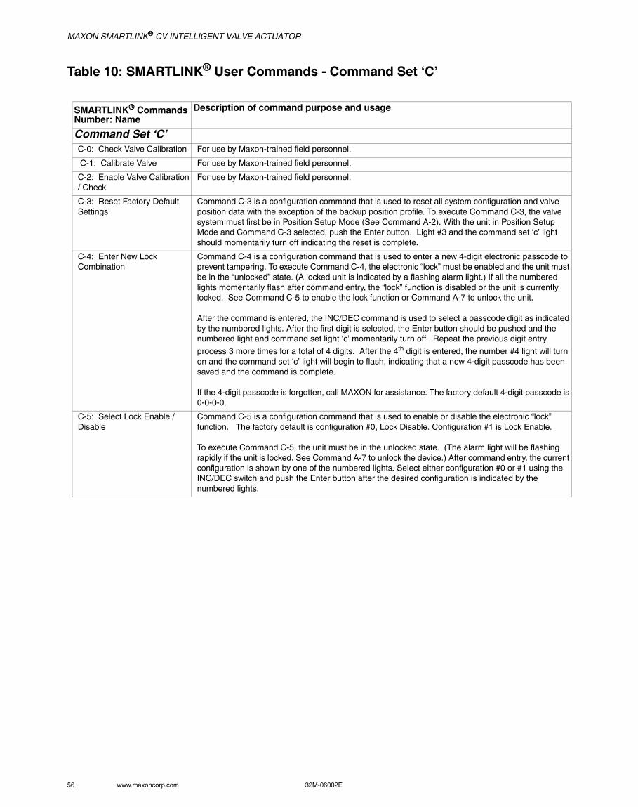
MAXON SMARTLINK® CV INTELLIGENT VALVE ACTUATOR
56 www.maxoncorp.com 32M-06002E
Table 10: SMARTLINK® User Commands - Command Set ‘C’
SMARTLINK® CommandsNumber: Name
Description of command purpose and usage
Command Set ‘C’C-0: Check Valve Calibration For use by Maxon-trained field personnel.
C-1: Calibrate Valve For use by Maxon-trained field personnel.
C-2: Enable Valve Calibration / Check
For use by Maxon-trained field personnel.
C-3: Reset Factory Default Settings
Command C-3 is a configuration command that is used to reset all system configuration and valve position data with the exception of the backup position profile. To execute Command C-3, the valve system must first be in Position Setup Mode (See Command A-2). With the unit in Position Setup Mode and Command C-3 selected, push the Enter button. Light #3 and the command set ‘c’ light should momentarily turn off indicating the reset is complete.
C-4: Enter New Lock Combination
Command C-4 is a configuration command that is used to enter a new 4-digit electronic passcode to prevent tampering. To execute Command C-4, the electronic “lock” must be enabled and the unit must be in the “unlocked” state. (A locked unit is indicated by a flashing alarm light.) If all the numbered lights momentarily flash after command entry, the “lock” function is disabled or the unit is currently locked. See Command C-5 to enable the lock function or Command A-7 to unlock the unit.
After the command is entered, the INC/DEC command is used to select a passcode digit as indicated by the numbered lights. After the first digit is selected, the Enter button should be pushed and the numbered light and command set light ‘c’ momentarily turn off. Repeat the previous digit entry
process 3 more times for a total of 4 digits. After the 4th digit is entered, the number #4 light will turn on and the command set ‘c’ light will begin to flash, indicating that a new 4-digit passcode has been saved and the command is complete.
If the 4-digit passcode is forgotten, call MAXON for assistance. The factory default 4-digit passcode is 0-0-0-0.
C-5: Select Lock Enable / Disable
Command C-5 is a configuration command that is used to enable or disable the electronic “lock” function. The factory default is configuration #0, Lock Disable. Configuration #1 is Lock Enable.
To execute Command C-5, the unit must be in the unlocked state. (The alarm light will be flashing rapidly if the unit is locked. See Command A-7 to unlock the device.) After command entry, the current configuration is shown by one of the numbered lights. Select either configuration #0 or #1 using the INC/DEC switch and push the Enter button after the desired configuration is indicated by the numbered lights.
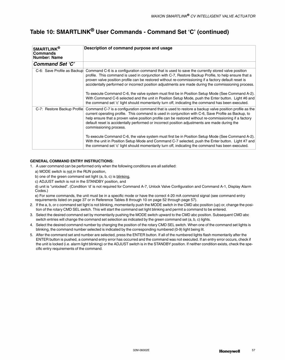
MAXON SMARTLINK® CV INTELLIGENT VALVE ACTUATOR
32M-06002E 57
Table 10: SMARTLINK® User Commands - Command Set ‘C’ (continued)
GENERAL COMMAND ENTRY INSTRUCTIONS:1. A user command can be performed only when the following conditions are all satisfied:
a) MODE switch is not in the RUN position,b) one of the green command set light (a, b, c) is blinking,c) ADJUST switch is not in the STANDBY position, andd) unit is “unlocked”. (Condition ‘d’ is not required for Command A-7, Unlock Valve Configuration and Command A-1, Display Alarm Codes.)e) For some commands, the unit must be in a specific mode or have the correct 4-20 mA command signal (see command entry requirements listed on page 37 or in Reference Tables 8 through 10 on page 52 through page 57).
2. If the a, b, or c command set light is not blinking, momentarily push the MODE switch in the CMD abc position (up) or, change the posi-tion of the rotary CMD SEL switch. This will start the command set light blinking and permit a command to be entered.
3. Select the desired command set by momentarily pushing the MODE switch upward to the CMD abc position. Subsequent CMD abc switch entries will change the command set selection as indicated by the green command set (a, b, c) lights.
4. Select the desired command number by changing the position of the rotary CMD SEL switch. When one of the command set lights is blinking, the command number selected is indicated by the corresponding numbered (0-9) light being lit.
5. After the command set and number are selected, press the ENTER button. If all of the numbered lights flash momentarily after the ENTER button is pushed, a command entry error has occurred and the command was not executed. If an entry error occurs, check if the unit is locked (i.e. alarm light blinking) or the ADJUST switch is in the STANDBY position. If neither condition exists, check the spe-cific entry requirements of the command.
SMARTLINK® CommandsNumber: Name
Description of command purpose and usage
Command Set ‘C’ C-6: Save Profile as Backup Command C-6 is a configuration command that is used to save the currently stored valve position
profile. This command is used in conjunction with C-7, Restore Backup Profile, to help ensure that a proven valve position profile can be restored without re-commissioning if a factory default reset is accidentally performed or incorrect position adjustments are made during the commissioning process.
To execute Command C-6, the valve system must first be in Position Setup Mode (See Command A-2). With Command C-6 selected and the unit in Position Setup Mode, push the Enter button. Light #6 and the command set ‘c’ light should momentarily turn off, indicating the command has been executed.
C-7: Restore Backup Profile Command C-7 is a configuration command that is used to restore a backup valve position profile as the current operating profile. This command is used in conjunction with C-6, Save Profile as Backup, to help ensure that a proven valve position profile can be restored without re-commissioning if a factory default reset is accidentally performed or incorrect position adjustments are made during the commissioning process.
To execute Command C-6, the valve system must first be in Position Setup Mode (See Command A-2). With the unit in Position Setup Mode and Command C-7 selected, push the Enter button. Light #7 and the command set ‘c’ light should momentarily turn off, indicating the command has been executed.
Commercial & Industrial Combustion (C&IC)
Honeywell
MUNCIE, INDIANA, USAMaxon201 East 18th StreetP.O. Box 2068Muncie, IN 47307-0068Tel: 765.284.3304Fax: 765.286.8394
GOLDEN VALLEY, MINNESOTA, USAHoneywell Automation and Control Solutions1985 Douglas Drive NorthGolden Valley, MN 55422-3992www.honeywell.com
Canada Sales OfficeTORONTOMaxon Industrial Equipment3333 Unity DriveMississauga, Ontario L5L 3S6Tel: 800.489.4111Fax: 855.262.0792
European Sales OfficeBELGIUMMaxon International BVBALuchthavenlaan 16-181800 Vilvoorde, BelgiumTel: 32.2.255.09.09Fax: 32.2.251.82.41
Asia/Pacific Sales OfficeSINGAPOREMaxonHoneywell Building17 Changi Business Park, Central 1Singapore 486073Tel: 65.6580.3358Fax:65.6580.3345
China Sales OfficeSHANGHAIMaxon Combustion Equipment(Shanghai) Co., Ltd.1st Floor & Section A, 4th Floor225 Meisheng RoadWai Gao Qiao Free Trade ZonePudong New AreaShanghai 200131, P.R. ChinaTel: 86.21.5866.1166Fax:86.21.5868.1569
India Sales OfficePUNEMaxon53, 54, 56, 57 Hadapsar Industrial EstateEnvironmental & Combustion ControlsSapphire Building 2nd Floor, A WingPune 411013 IndiaTel: 91.98.50907894Tel: 91.20.66008330Tel: 91.20.66008509Fax: 91.20.66039979
Sales Offices &Representatives Worldwide
maxoncorp.comcustomer.honeywell.com
32M-06002E - Imperial versionMaxon P/N 50120623-001/A01August 2015 Printed in USA© 2015 Honeywell International Inc.


![MAXON SMARTLINK CVcicsa-maxon.com.mx/media/V--lvula-de-mariposa-SMARTLINK.pdf1 - 33.9 N.m X - Special Software Version [2] 1C - Standard software Language A - English X - Special Rotation](https://img.pdfslide.us/doc/110x75/609997a6ce05bd78a2193493/maxon-smartlink-cvcicsa-maxoncommxmediav-lvula-de-mariposa-1-339-nm-x.jpg)