Embed Size (px)
Citation preview
International Journal of Science and Research (IJSR) ISSN (Online): 2319-7064
Index Copernicus Value (2013): 6.14 | Impact Factor (2013): 4.438
Volume 4 Issue 1, January 2015 www.ijsr.net
Licensed Under Creative Commons Attribution CC BY
Maximum Power Generation by Integrating Solar & Wind System Using Fuzzy for Voltage Regulation in
Smart Grid
Priya .N1, Saranya .C .M2
Department of Power System Engineering, Valliammai Engineering College, Chennai, India
Abstract: This paper presents the voltage regulation of hybrid power system with the inter connection of PV system, wind energy conversion system. The voltage regulation is done with the help of fuzzy logic controller and zeta converter through simulations using MATLAB / SIMULINK. In the proposed system the solar energy and wind energy is combined to produce electrical energy. Then power electronic converters are used for the conversion of ac to dc and dc to ac. In which a control circuit is designed using fuzzy logic controller for gate signals for the voltage regulation of the hybrid energy system. Then the hybrid energy system is connected to the grid from which the energy is supplied to the loads. The voltage regulation is done for both AC and DC loads. Keywords: Hybrid power systems, Photovoltaic systems, Smart grids, Wind power generation, Fuzzy Logic Controller 1. Introduction According to many renewable energy experts, a small "hybrid" electric system that combines home wind electric and home solar electric (photovoltaic or PV) technologies offers several advantages over either single system[1]. In some countries wind speeds are low in the summer when the sun shines brightest and longest. The wind is strong in the winter when less sunlight is available. Because the peak operating times for wind and solar systems occur at different times of the day and year, hybrid systems are more likely to produce power when you need it. The major advantage of solar / wind hybrid system is that when solar and wind power production are used together, the reliability of the system is enhanced[3].The ZETA converter topology provides a positive regulated output voltage from an input voltage that varies above and below the output voltage. It is also used to regulating an unregulated input-power supply. Fuzzy logic has rapidly become one of the most successful of today’s technology for developing sophisticated control system. With it aid complex requirement so may be implemented in amazingly simple, easily minted and inexpensive controllers. The past few years have witnessed a rapid growth in number and variety of application of fuzzy logic[9]. The application range from consumer products such as cameras ,camcorder ,washing machines and microwave ovens to industrial process control ,medical instrumentation ,and decision support system .many decision-making and problem solving tasks are too complex to be understand quantitatively however ,people succeed by using knowledge that is imprecise rather than precise . Fuzzy logic is all about the relative importance of precision .fuzzy logic has two different meanings .in narrow senses, fuzzy logic is a logical system which is an extension of multi valued logic but in wider sense fuzzy logic is synonymous with the theory of fuzzy sets.
2. System Description and Modeling In hybrid power systems, a number of renewable energy generators and storage components are combined to meet the energy demand of the power system. It mainly includes PV generators and wind generators, the others sources of electrical energy can also be added to meet the energy demand. It is essential to know the energy demand and the resources available at that site before developing a hybrid power system. The energy planners must study the availability of solar energy, wind, and other potential resources at that site. This will help them to design what kind of hybrid power system will be suitable to meet the demand. In this paper, a brief technical description of some of the different hybrid power system configurations is considered in Fig1.
Figure 1: Smart Grid Layout
A. Modelling and Design of a Photovoltaic Module The circuit of the solar cell model, which consists of a photocurrent, diode, parallel resistor (leakage current) and a series resistor; is shown in Fig. 3. According to both the PV
Paper ID: SUB15506 1418
International Journal of Science and Research (IJSR) ISSN (Online): 2319-7064
Index Copernicus Value (2013): 6.14 | Impact Factor (2013): 4.438
Volume 4 Issue 1, January 2015 www.ijsr.net
Licensed Under Creative Commons Attribution CC BY
cell circuit shown in Fig. 3 and Kirchhoff’s circuit laws, the photovoltaic current can be presented as follows,
IPV=[Igc – Io [exp(evd/KFTc) -1]-(Vd/Rp) ]
Figure 2: Single Diode Model of a PV Cell
electric charge = 1.6 x 10⁻¹⁹Coulombs, K is Boltzmann’sconstant = 1.38 x10 -19 J/K, F is the cell idealizing factor, Tc is the cell’s absolute temperature, vd is the diode voltage, and Rp is the parallel resistance. The photocurrent (Igc) mainly depends on the solar irradiation and cell temperature,
Figure 3: Single diode PV equivalent circuit
According to both the PV cell circuit shown in Fig. and Kirchhoff’s circuit laws, the photovoltaic current can be presented as follows 𝐼𝐼 = 𝐼𝐼𝑝𝑝𝑣𝑣 − 𝐼𝐼𝑜𝑜 [exp (𝑉𝑉 +𝑅𝑅𝑠𝑠𝐼𝐼𝑉𝑉𝑡𝑡𝑎𝑎) − 1] − (𝑉𝑉 +𝑅𝑅𝑠𝑠𝐼𝐼𝑅𝑅𝑝𝑝) Ipv= photovoltaic current Io= saturation current Vt= NS k T/q, thermal voltage of array Ns = cell connected in series T = is the temperature of the p-n junction The output current from the photovoltaic array is Using suitable approximations, 𝐼𝐼 = 𝐼𝐼𝑠𝑠𝑐𝑐 − 𝐼𝐼𝑑𝑑 𝐼𝐼𝑑𝑑 = 𝐼𝐼𝑜𝑜 (𝑒𝑒𝑞𝑞𝑉𝑉𝑑𝑑𝐾𝐾𝑇𝑇−1) 𝐼𝐼 = 𝐼𝐼𝑠𝑠𝑐𝑐 − 𝐼𝐼𝑜𝑜 (𝑒𝑒𝑞𝑞 (𝑉𝑉+𝐼𝐼𝑅𝑅𝑠𝑠𝑛𝑛𝐾𝐾𝑇𝑇) Where, I is the photovoltaic cell current,
V is the PV cell voltage, T is the temperature (in Kelvin) B. Wind Power Generation System The wind power generation system is equipped with variable speed generator. Apart from the wind generator, wind power generation system consists of another three parts namely, wind speed, wind turbine and drive train. Wind turbine model A wind turbine converts kinetic energy in a moving air stream to electric energy. The wind turbine model is implemented depending upon the Tip Speed Ratio (TSR) and Cp coefficient. The tip-speed ratio is defined as: λ = ωR / υ • Power in wind is proportional cube of wind speed
P = 0.5 ϱ.A.Vᵌ.Cp Where, ϱ = Air density A = Area swept by blade V = Wind speed
• A wind turbine can only extract a part of the power from the wind,which is limited by Beta.
• This fraction is described by the power coefficient Cp which is the function of blade pitch angle (β) and tip speed ratio (λ).
Figure 4: Block diagram of proposed system
C. Power Control System 1. Photovoltaic control system MPPT algorithms are necessary in PV applications in order to obtain the maximum power from a solar array because the MPP (Maximum Power Point) of a solar panel varies with the irradiation and temperature. The incremental conductance uses the PV array's incremental conductance dI/dV to compute the sign of dP/dV. It does this using an expression derived from the condition that, at the maximum power point, dP/dV = 0. Beginning with this condition, it is possible to show that, at the MPP dI/dV =I/V. Thus, incremental conductance can determine that the MPPT has reached the MPP and stop perturbing the operating point.
Paper ID: SUB15506 1419
International Journal of Science and Research (IJSR) ISSN (Online): 2319-7064
Index Copernicus Value (2013): 6.14 | Impact Factor (2013): 4.438
Volume 4 Issue 1, January 2015 www.ijsr.net
Licensed Under Creative Commons Attribution CC BY
If this condition is not met, the direction in which the MPPT operating point must be perturbed can be calculated using the relationship between dI/dV and I/V. The algorithm is simulated by writing the algorithm in M-file. The subsystem is shown in below figure
Figure 5: Subsystem Implementation of incremental
conductance algorithm D. Double Brige Rectifier and ZETA Converter Due to the variations in wind speed, the output power of the wind turbine induction generator experiences variations in frequency and amplitude. Therefore, a controllable ac/dc converter is used to smooth the wind turbine output power before being supplied to other electronic devices. The ZETA converter topology provides a positive regulated output voltage from an input voltage that varies above and below the output voltage. It is also used to regulating an unregulated input-power supply. Zeta converter is a fourth-order DC-DC converter made up of two inductors and two capacitors and capable of operating in either step-up or step-down mode. E. Fuzzy Logic Controller Fuzzy logic expressed operational laws in linguistics terms instead of mathematical equations. Many systems are too complex to model accurately, even with complex mathematical equations; therefore traditional methods become infeasible in these systems. The fuzzy logic controller has three main components a. Fuzzification b. Fuzzy inference c. Defuzzification
Figure 6: Subsystem Implementation of FLC along with
ZETA converter
Fuzzy logic linguistic terms are often expressed in the form of logical implication, such as if then rules. These rules define a range of values known as fuzzy membership functions. The inputs of the fuzzy controller are expressed in several linguist levels. As shown in the table,
Table 1: Fuzzy Control rule
These levels can be described as Positive big (PB), Positive medium (PM), Positive small (PS) Negative small (NS), Negative medium (NM), Negative big (NB) or in other levels. Each level is described by fuzzy set.
Paper ID: SUB15506 1420

International Journal of Science and Research (IJSR) ISSN (Online): 2319-7064
Index Copernicus Value (2013): 6.14 | Impact Factor (2013): 4.438
Volume 4 Issue 1, January 2015 www.ijsr.net
Licensed Under Creative Commons Attribution CC BY
Figure 7: Seven levels of fuzzy membership functions
3. Simulation and Analysis of Results
In this overall simulations shows the integration of solar and wind energy system, constant 0.5 refers input current to the PV panel and 85 is the insolation of the PV panel which can be varied due to the change in climatic condition. PV Module requires the input current and insolation. The Output of the PV panel given to the controlled voltage source.
Figure 8: Simulink model of hybrid power system
Controlled voltage source- Convert the Simulink input signal into the equivalent voltage source. The generated voltage is driven by the input signal of the block. Source type is AC. The output voltage and current from the solar panel is the input to MPPT and Here the MPPT is designed to give the Gate pulse to the switch used in DC-DC Boost converter. Incremental conductance Algorithm tracks maximum Power under rapidly varying condition. Obtain duty cycle by its algorithm and feed to the PWM block to generate require gate pulse for Boost converter.
Figure 9: Input Current and Voltage from solar panel
Based on the simulation result voltage range from 0-114V and the current value nearly 115A obtained from the solar panel. Hence this is given as an input of Boost converter and also to MPPT. Boost converter (step-up converter) is a DC-DC power converter with an output voltage greater than its input voltage. Boost type dc-dc converter is used to feed the power generated by the PV array to the load .The input of Boost converter is about 114V but the gained output voltage ranges from 550-600V is simulated using MATLAB.
Figure 10: Output waveform from Boost converter
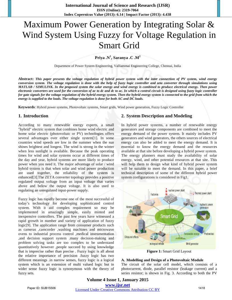
Zeta converter is used to regulating an unregulated input-power supply. Regulated output voltage obtain from the zeta converter ranges from 450-500V to feed the load.
Paper ID: SUB15506 1421
International Journal of Science and Research (IJSR) ISSN (Online): 2319-7064
Index Copernicus Value (2013): 6.14 | Impact Factor (2013): 4.438
Volume 4 Issue 1, January 2015 www.ijsr.net
Licensed Under Creative Commons Attribution CC BY
Figure 11: Output waveform from ZETA converter
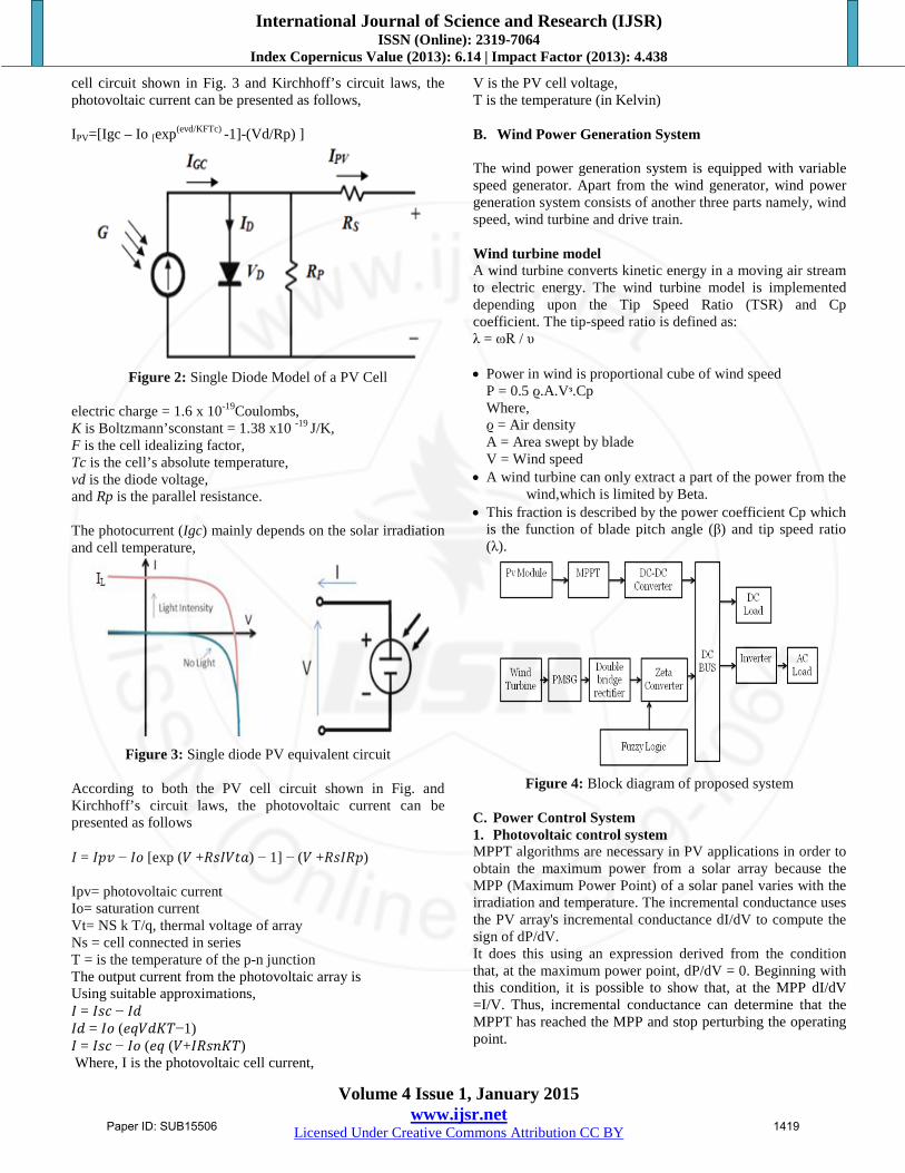
Figure 12: Simulated Inverter voltage waveform
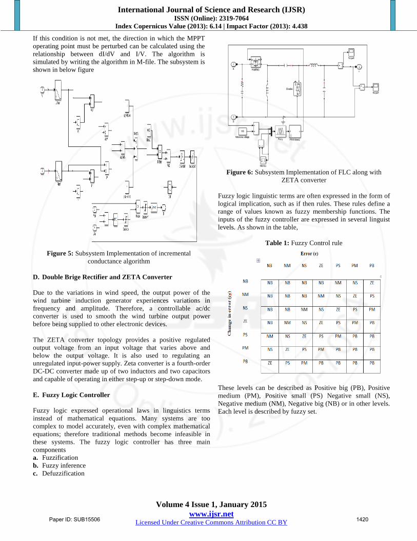
Simulated inverter device which produces a multiple step sinusoidal AC waveform is referred to as a sine wave inverter. Here current and voltage waveform is simulated by using MATLAB/SIMULINk.
Figure 13: Simulated inverter current waveform
4. Conclusion The results show that obtaining Maximum Power by using MPPT-Incremental conductance method. And also by DC-DC Boost converter, the voltage level is gained to feed the load. DC-DC converters (Boost) are analyzed with a view of their use in PV (photovoltaic) systems, as the photovoltaic generator exhibits non-linear characteristics due to the change in environmental condition and load variation. As the efficiency of PV panels is low it becomes mandatory to extract maximum power from the PV panel at a given period of time, hence the load voltage is maintained constant. Regulated voltage is obtained by using zeta converter under fuzzy logic controller. References [1] Lin Xu; XinboRuan; Chengxiong Mao; Buhan Zhang; Yi
Luo, "An Improved Optimal Sizing Method for Wind-Solar-Battery Hybrid Power System," Sustainable Energy, IEEE Transactions, vol.4,no.3, pp.774,785, July 2013.
[2] Nagaraj, R., "Renewable energy based small hybrid power system for desalination applications in remote locations," Power Electronics (IICPE), 2012 IEEE 5th India International Conference,vol., no., pp.1, 5, 6-8 Dec. 2012
[3] E. Miller, “Smart grids – a smart idea?,” Renewable Energy Focus Magazine, vol. 10, pp. 62-67, Sep.-Oct. 2009.
[4] Ardakani, F.J.; Riahy, G.; Abedi, M., "Optimal sizing of a grid connected hybrid system for north-west of Iran-case study, "Environment and Electrical Engineering (EEEIC), 2010 9th International Conference, vol., no., pp.29, 32, 16-19 May 2010.
[5] J.C.H. Phang, D.S.H. Chan, and J.R. Philips, “Accurate analytical method for the extraction of solar cell model parameter,” IEEE Electronics Letters, vol. 20, pp.406-408, May 1984.
[6] Woyte, A.; Van Thong, Vu; Belmans, R.; Nijs, J., "Voltage fluctuations on distribution level introduced by photovoltaic systems," Energy Conversion, IEEE Transactions, vol.21, no.1,pp.202,209, March 2006.
[7] Chompoo-inwai, C.; Wei-Jen Lee; Fuangfoo, P.; Williams, M.; Liao, J.R., "System impact study for the interconnection of wind generation and utility system," Industry Applications, IEEETransactions, vol.41, no.1, pp.163,168, Jan.-Feb. 2005.
[8] Chedid, R.; Karaki, S.; Rifai, A., "A multi-objective design methodology for hybrid renewable energy systems," Power Tech,2005 IEEE Russia , vol., no., pp.1, 6, 27-30 June 2005.
[9] Kellogg, W. D.; Nehrir, M.H.; Venkataramanan, G.; Gerez, V., "Generation unit sizing and cost analysis for stand-alone wind, photovoltaic, and hybrid wind/PV systems," Energy Conversion, IEEE Transactions, vol.13, no.1, pp.70, 75, Mar 1998.
[10] Chedid, R.; Akiki, H.; Rahman, S., "A decision support technique for the design of hybrid solar-wind power
Paper ID: SUB15506 1422
International Journal of Science and Research (IJSR) ISSN (Online): 2319-7064
Index Copernicus Value (2013): 6.14 | Impact Factor (2013): 4.438
Volume 4 Issue 1, January 2015 www.ijsr.net
Licensed Under Creative Commons Attribution CC BY
systems," Energy Conversion, IEEE Transactions, vol.13, no.1, pp.76, 83, Mar 1998.
[11] Shrestha, G.B.; Goel, L., "A study on optimal sizing of stand-alone photovoltaic stations," Energy Conversion, IEEE Transactions, vol.13, no.4, pp.373, 378, Dec 1998.
[12] Chedid, R.; Rahman, S., "Unit sizing and control of hybrid wind solar power systems," Energy Conversion, IEEE Transactions, vol.12, no.1, pp.79, 85, Mar 1997.
Author Profile
Mrs. N. Priya received her B.E. degree in Electrical and Electronics Engineering from Adhi Parashakthi Engineering College, Madras University, Melmaruvathur, Tamilnadu, India in 2002. She received her M.E degree in Power Electronics and Drives from
College of Engineering Guindy, Anna University, Chennai, Tamilnadu, India in 2011. Her current research interests include renewable energy resources and power optimization. She is a member of ISTE.
Ms. C. M. Saranya received her B.E degree in electrical and electronics engineering from GKM College of Engineering And Technology affiliated to Anna University, Chennai in 2013 and currently a student doing M.E Power System Engineering in Valliammai
Engineering College affiliated to Anna University. Her main research interests are Renewable energy resources and microgrid.
Paper ID: SUB15506 1423