Embed Size (px)
Citation preview
Maximizing Spatial Reuse In Indoor Environments
Xi Liu†
Thesis Committee:Srinivasan Seshan (co-chair)†
Peter Steenkiste (co-chair)†
David Anderson†
Konstantina Papagiannaki‡
†Carnegie Mellon University‡Intel Labs Pittsburgh
Abstract
Wireless technologies have gained tremendous popularity in recent years, resulting in a densedeployment of wireless devices in every indoor environment. High densities of wireless devicesdramatically increase the severity of the interference problem in these indoor environments.Existing solutions to this problem, including frequency division, time division, and MIMOspatial multiplexing, all have limitations and cannot fully solve the problem.
In this thesis, we show the effectiveness of another solution in mitigating wireless inter-ference in indoor environments: increasing spatial reuse. We explore two techniques: powercontrol and directional transmission. We show in this thesis that both techniques can significantlyimprove network capacity by allowing simultaneous transmissions.
While both power control and directional transmission have been widely used in outdoorscenarios, different solutions are required to meet the new challenges offered by the uniquecharacteristics of the indoor environments, i.e., both APs and clients are chaotically deployedand there are usually multiple RF paths between the AP and the client. There are two challengesin system design, choosing the appropriate power levels / antenna orientations and choosing theright MAC protocol.
In this thesis, we first evaluate the benefits, i.e., spatial reuse opportunities, of both directionaltransmission and power control. Based on this evaluation, we present the motivation, challenges,and design of three systems: 1) Speed, a distributed directional antenna system with bothdirectional APs and clients designed to solve the interference problem in the future due to thehighest level of spatial reuse, 2) DIRC, a centralized directional antenna system with directionalAPs designed for enterprise networks with omnidirectional clients, and 3) an omnidirectionalantenna system with power control, designed to improve spatial reuse of existing omnidirectionalnodes.
1
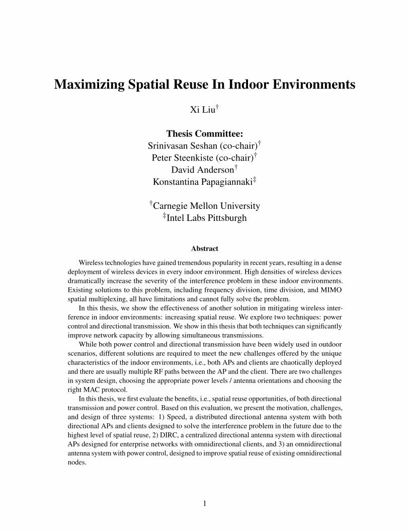
1 IntroductionWireless technologies have gained tremendous popularity in recent years, resulting in a densedeployment of wireless devices in every indoor environment such as conference rooms, enterprisenetworks and homes. For example, it has been envisioned that in the future, every gadget andevery appliance in home will have a wireless radio, which may add up to hundreds of wirelessradios in future homes. High densities of wireless devices dramatically increase the severity of theinterference problem in these indoor environments.
From a physics point of view, there are three orthogonal approaches to isolate wireless devicesand to prevent wireless interference: frequency, time, and space. First, multiple wireless devicesthat operate on orthogonal frequencies do not interfere with each other. However, this approachis limited by the fact that the amount of unlicensed frequency is not infinite. Second, interferingdevices that operate in the same wireless channel can avoid interference by not transmitting at thesame time, by using CSMA and TDMA. This approach does not suffice either because it does notimprove network capacity, i.e., the link throughput of each node is inversely proportional to thenumber of interfering nodes. Finally, existing space domain solutions focus on spatial diversity,e.g., spatial multiplexing with MIMO antenna configurations. The network capacity of such MIMOnetworks, however, is limited by multipath channel conditions, i.e., the rank of the channel matrixbetween the sender and the receiver.
In this thesis, we show the effectiveness of another solution in the space domain in mitigatingwireless interference in indoor environments: increasing spatial reuse. We explore two techniques:power control and directional transmission. We show in this thesis that both techniques cansignificantly improve network capacity by allowing simultaneous transmissions.
Directional transmission can confine the signal at both senders and receivers to a narrow region,which allows the senders to transmit simultaneously without interfering. Power control can alsoachieve simultaneous transmissions by tuning the power levels on wireless devices. While bothpower control and directional transmission have been widely used in outdoor scenarios, differentsolutions are required to meet the new challenges offered by the unique characteristics of the indoorenvironments. There are two challenges in system design, choosing the appropriate power levels /antenna orientations and choosing the right MAC protocol. Power control has been widely used incellular phone networks to improve spatial reuse, where power levels are reduced to the minimumlevels required to decode the frames. While such power reduction is optimal for celluar networks,i.e., honey-grids of base stations, we show in this thesis that it fails to maximize spatial reusein indoor environments where both APs and clients are deployed more chaotically. Directionalantennas have been widely used in outdoor applications to extend communication range. However,unlike in outdoor scenarios where the sender and the receiver orient directly towards each other, inindoor environments, choosing the right antenna orientations is challenging since there are usuallymultiple paths between the sender and the receiver and the optimal antenna orientations depend oninterfering transmissions. The second challenge for both power control and directional transmissionis the MAC protocol, which plays an important role in exploiting spatial reuse opportunities.Unfortunately, existing carrier sensing based solutions, e.g., that tune CCA thresholds or that usedirectional network allocation vectors (DNAV), interact poorly with power control and directionaltransmission and thus perform poorly.
The rest of the thesis proposal is organized as follows. Next, we evaluate the benefits, i.e., spatial
2
reuse opportunities, of both directional transmission and power control (Section 2). Based on thisevaluation, we present the motivation, challenges, and design of three systems in the next threesections: 1) DIRC, a centralized directional antenna system with directional APs (Section 3), 2)Speed, a distributed directional antenna system with both directional APs and clients (Section 4),and 3) an omnidirectional antenna system with power control (Section 5). The Speed system, whichhas the highest level of spatial reuse but involves the most deployment efforts, is what we envisionto be the solution to the interference problem in the future. The DIRC system is primarily designedfor enterprise wireless networks where directional APs are deployed to provide wireless services toomnidirectional users. The power control protocol is designed to improve spatial reuse for existingomnidirectional nodes.
2 Benefiting from Power Control and Directional AntennasIn this section, we use measurements collected in two indoors scenarios to evaluate the spatial reuseopportunites from power control and directional antennas. For power control, we compare no powercontrol (NoPC) versus optimal power control (OptPC). For directional antennas, we compare fouroptions of directional antenna locations, i.e., on APs (dir-tx,omn-rx), on clients (omn-tx,dir-rx), onboth (dir-tx,dir-rx), or neither (omn-tx,omn-rx). Since power control is orthogonal to directionality,we consider all combinations, i.e., four directional antenna configurations both with and withoutpower control. In this section, we focus on spatial reuse opportunities, i.e., the best capacity that canbe achieved from each combination, by using centralized algorithms called MaxCAP and OptPC tosteer directional antennas and to choose power levels respectively. Both algorithms do an exhaustivesearch over the entire space.
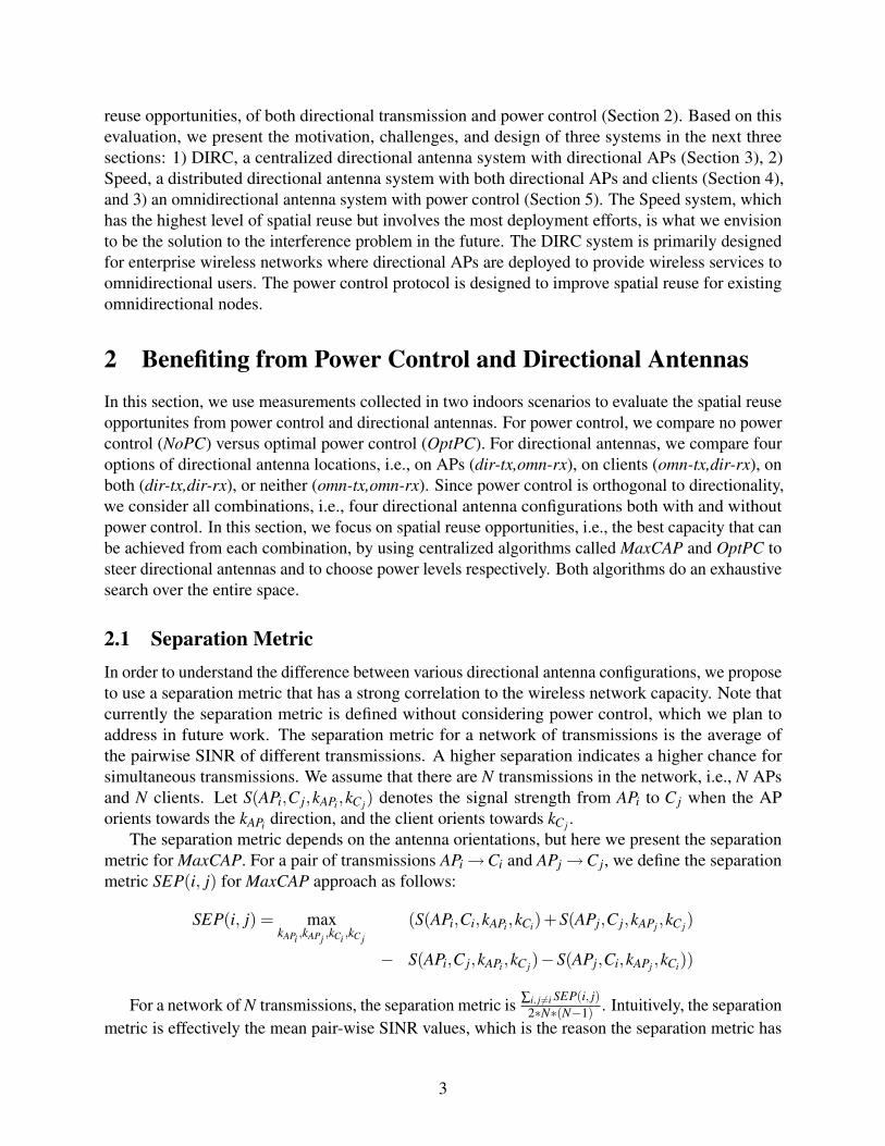
2.1 Separation MetricIn order to understand the difference between various directional antenna configurations, we proposeto use a separation metric that has a strong correlation to the wireless network capacity. Note thatcurrently the separation metric is defined without considering power control, which we plan toaddress in future work. The separation metric for a network of transmissions is the average ofthe pairwise SINR of different transmissions. A higher separation indicates a higher chance forsimultaneous transmissions. We assume that there are N transmissions in the network, i.e., N APsand N clients. Let S(APi,C j,kAPi,kC j) denotes the signal strength from APi to C j when the APorients towards the kAPi direction, and the client orients towards kC j .
The separation metric depends on the antenna orientations, but here we present the separationmetric for MaxCAP. For a pair of transmissions APi →Ci and APj →C j, we define the separationmetric SEP(i, j) for MaxCAP approach as follows:
SEP(i, j) = maxkAPi ,kAPj ,kCi ,kCj
(S(APi,Ci,kAPi,kCi)+S(APj,C j,kAPj ,kC j)
− S(APi,C j,kAPi,kC j)−S(APj,Ci,kAPj ,kCi))
For a network of N transmissions, the separation metric is ∑i, j 6=i SEP(i, j)2∗N∗(N−1) . Intuitively, the separation
metric is effectively the mean pair-wise SINR values, which is the reason the separation metric has
3
C1
AP1
AP2
d1
d2
(a) Distance Separation
C1
AP1 AP2
α
(b) Angular Separation
Figure 1: Two Components of Separation Metric
AP1
AP2
AP3
AP4
AP5
AP6
C1
C2
C3
C4
C5
C6
(a) Campus
AP1 AP2
AP3
AP4
AP5
AP6C1 C2C3
C4
C5
C6
(b) Lab
C1
AP1
C2
AP2
(c) Topo 1
C1
AP1
C2
AP2
(d) Topo 2
C1
C2
AP1
AP2
(e) Topo 3
AP2
C1,C2
AP1
(f) Topo 4AP2C1,C2
AP1
(g) Topo 5AP2C1,C2
AP1
(h) Topo 6
Figure 2: Experimental Map
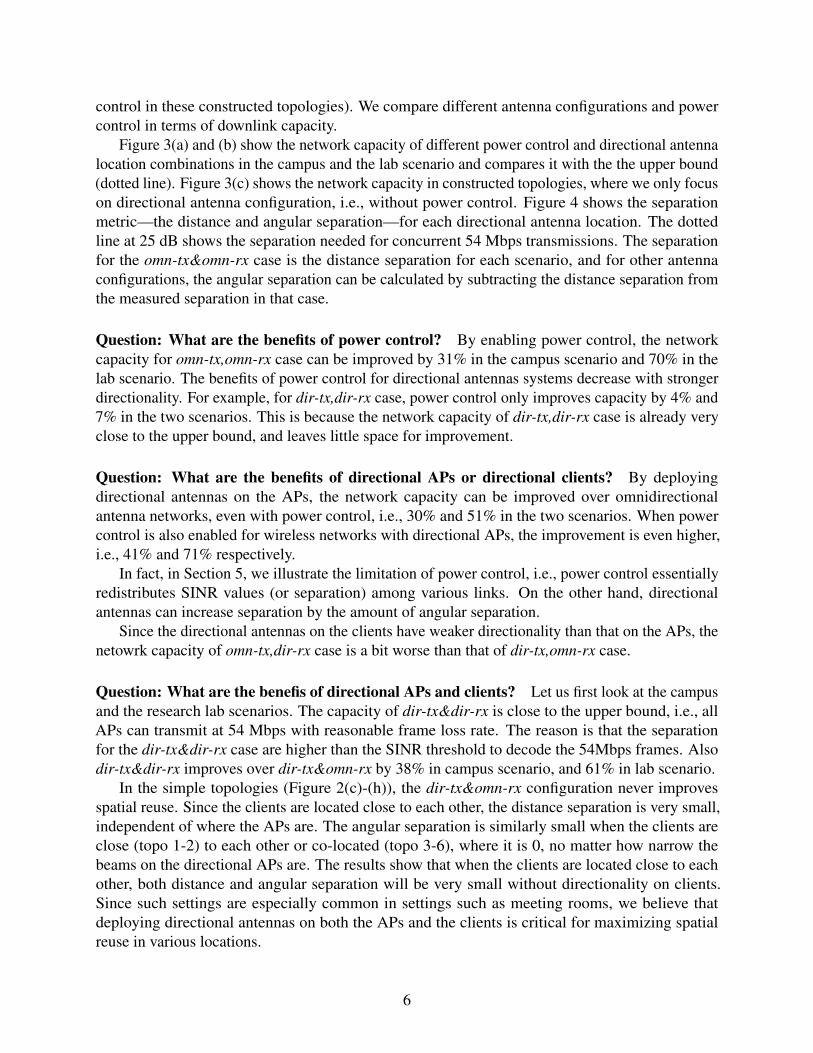
a strong correlation with the network capacity. So given that the SINR threshold for 54Mbps is25dB, for all transmissions to happen simultaneously at 54Mbps, the separation metric need to be atleast 25dB.
Distance and Angular Separation In essence, the separation comes from two sources, distanceseparation and angular separation. The distance separation is due to the difference between thedistance (or more accurately, pathloss) from the client to its own AP and to the interfering AP.Figure 1(a) shows an example of distance separation, where the client is closer to its AP thanthe interfering AP, i.e., d1 < d2. The angular separation is due to the ability of the directionalantennas to focus its energy on a particular direction. Figure 1(b) shows an example of angularseparation, where the orientations from the client to two different APs are separated by α . Notethat angular separation only applies to directional antennas, and for omnidirectional antennas, theangular separation will always be 0.
The separation is the sum of both angular and distance separation. In order to evaluate theseparation of a particular node setup and scenario, measurements need to be taken in that scenario.
4
0
50
100
150
200
250
dir-tx,dir-rx dir-tx,omn-rx omn-tx,dir-rx omn-tx,omn-rx
Net
wor
k C
apac
ity (
Mbp
s)Directional Antenna Configuration
MaxCAP,OptPCMaxCAP,NoPCMaxSNR,NoPC
(a) Network Capacity (Campus)
0
50
100
150
200
250
dir-tx,dir-rx dir-tx,omn-rx omn-tx,dir-rx omn-tx,omn-rx
Net
wor
k C
apac
ity (
Mbp
s)
Directional Antenna Configuration
MaxCAP,OptPCMaxCAP,NoPCMaxSNR,NoPC
(b) Network Capacity (Lab)
0
50
100
150
200
Topo 1 Topo 2 Topo 3 Topo 4 Topo 5 Topo 6
Net
wor
k C
apac
ity (
Mbp
s)
Location / Topology
dir-tx,dir-rx,MaxCAPdir-tx,dir-rx,MaxSNR
dir-tx,omn-rx,MaxCAPdir-tx,omn-rx,MaxSNRomn-tx,dir-rx,MaxCAPomn-tx,dir-rx,MaxSNR
omn-tx, omn-rx
(c) Network Capacity (Topologies)
Figure 3: Network Capacity with Various Antenna Configurations, Power Control, and Ori-entation Algorithms
0
10
20
30
40
50
60
70
Campus Lab Topo 1 Topo 2 Topo 3 Topo 4 Topo 5 Topo 6
Sep
arat
ion
Met
ric (
dB)
Location / Topology
dir-tx,dir-rx,MaxCAPdir-tx,dir-rx,MaxSNR
dir-tx,omn-rx,MaxCAPdir-tx,omn-rx,MaxSNRomn-tx,dir-rx,MaxCAPomn-tx,dir-rx,MaxSNR
omn-tx, omn-rx
Figure 4: Separation Metric with Various Antenna Configurations and Orientation Algo-rithms
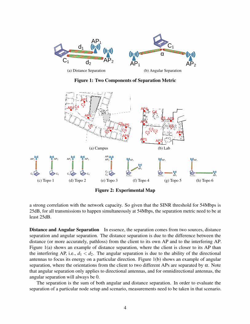
2.2 Characterizing Spatial ReuseNow we use measurements in two indoor testbeds to understand the benefits of power controland directional antennas. The experimental setup for this evaluation is as follows: Each client isequipped with two 35 degree fan beam, two 65 degree patch antennas, and one omnidirectionalantenna. The reason for such setup will be discussed in Section 4.2. We emulate a directional AP thathas 16 directions of 35 degree beams by steering a 35 degree patch antenna using a turn table, andwe also use an omnidirectional antenna on the AP to measure the performance of omnidirectionalAPs.
We take measurements in three different setups. The first setup is an office scenario in a campusbuilding, as shown in Figure 2(a). And the second setup is in a research lab that has more openspace than the office scenario, as shown in Figure 2(b). In both scenarios, we place the clientsin six locations and the APs in six other locations across the floor. The third setup is a morecontrolled environment, a large room with tables and machines around, where we construct thedifferent topologies of transmissions as shown in Figure 2(c)-(h), i.e., Topologies 1–6, to illustratethe fundamental problems of the directional APs only configuration (thus we do not evaluate power
5
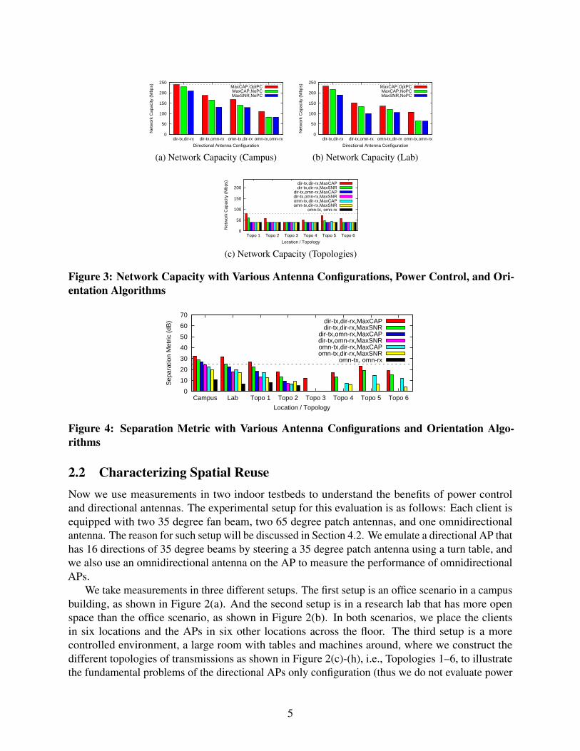
control in these constructed topologies). We compare different antenna configurations and powercontrol in terms of downlink capacity.
Figure 3(a) and (b) show the network capacity of different power control and directional antennalocation combinations in the campus and the lab scenario and compares it with the the upper bound(dotted line). Figure 3(c) shows the network capacity in constructed topologies, where we only focuson directional antenna configuration, i.e., without power control. Figure 4 shows the separationmetric—the distance and angular separation—for each directional antenna location. The dottedline at 25 dB shows the separation needed for concurrent 54 Mbps transmissions. The separationfor the omn-tx&omn-rx case is the distance separation for each scenario, and for other antennaconfigurations, the angular separation can be calculated by subtracting the distance separation fromthe measured separation in that case.
Question: What are the benefits of power control? By enabling power control, the networkcapacity for omn-tx,omn-rx case can be improved by 31% in the campus scenario and 70% in thelab scenario. The benefits of power control for directional antennas systems decrease with strongerdirectionality. For example, for dir-tx,dir-rx case, power control only improves capacity by 4% and7% in the two scenarios. This is because the network capacity of dir-tx,dir-rx case is already veryclose to the upper bound, and leaves little space for improvement.
Question: What are the benefits of directional APs or directional clients? By deployingdirectional antennas on the APs, the network capacity can be improved over omnidirectionalantenna networks, even with power control, i.e., 30% and 51% in the two scenarios. When powercontrol is also enabled for wireless networks with directional APs, the improvement is even higher,i.e., 41% and 71% respectively.
In fact, in Section 5, we illustrate the limitation of power control, i.e., power control essentiallyredistributes SINR values (or separation) among various links. On the other hand, directionalantennas can increase separation by the amount of angular separation.
Since the directional antennas on the clients have weaker directionality than that on the APs, thenetowrk capacity of omn-tx,dir-rx case is a bit worse than that of dir-tx,omn-rx case.
Question: What are the benefis of directional APs and clients? Let us first look at the campusand the research lab scenarios. The capacity of dir-tx&dir-rx is close to the upper bound, i.e., allAPs can transmit at 54 Mbps with reasonable frame loss rate. The reason is that the separationfor the dir-tx&dir-rx case are higher than the SINR threshold to decode the 54Mbps frames. Alsodir-tx&dir-rx improves over dir-tx&omn-rx by 38% in campus scenario, and 61% in lab scenario.
In the simple topologies (Figure 2(c)-(h)), the dir-tx&omn-rx configuration never improvesspatial reuse. Since the clients are located close to each other, the distance separation is very small,independent of where the APs are. The angular separation is similarly small when the clients areclose (topo 1-2) to each other or co-located (topo 3-6), where it is 0, no matter how narrow thebeams on the directional APs are. The results show that when the clients are located close to eachother, both distance and angular separation will be very small without directionality on clients.Since such settings are especially common in settings such as meeting rooms, we believe thatdeploying directional antennas on both the APs and the clients is critical for maximizing spatialreuse in various locations.
6
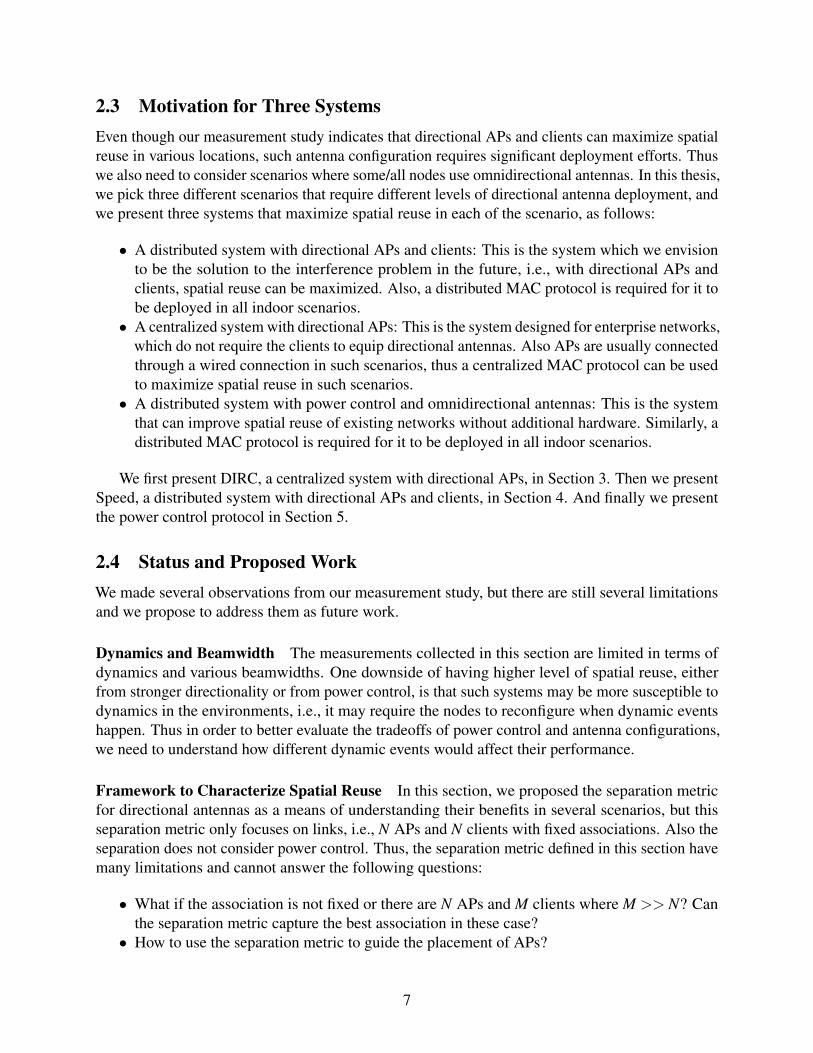
2.3 Motivation for Three SystemsEven though our measurement study indicates that directional APs and clients can maximize spatialreuse in various locations, such antenna configuration requires significant deployment efforts. Thuswe also need to consider scenarios where some/all nodes use omnidirectional antennas. In this thesis,we pick three different scenarios that require different levels of directional antenna deployment, andwe present three systems that maximize spatial reuse in each of the scenario, as follows:
• A distributed system with directional APs and clients: This is the system which we envisionto be the solution to the interference problem in the future, i.e., with directional APs andclients, spatial reuse can be maximized. Also, a distributed MAC protocol is required for it tobe deployed in all indoor scenarios.
• A centralized system with directional APs: This is the system designed for enterprise networks,which do not require the clients to equip directional antennas. Also APs are usually connectedthrough a wired connection in such scenarios, thus a centralized MAC protocol can be usedto maximize spatial reuse in such scenarios.
• A distributed system with power control and omnidirectional antennas: This is the systemthat can improve spatial reuse of existing networks without additional hardware. Similarly, adistributed MAC protocol is required for it to be deployed in all indoor scenarios.
We first present DIRC, a centralized system with directional APs, in Section 3. Then we presentSpeed, a distributed system with directional APs and clients, in Section 4. And finally we presentthe power control protocol in Section 5.
2.4 Status and Proposed WorkWe made several observations from our measurement study, but there are still several limitationsand we propose to address them as future work.
Dynamics and Beamwidth The measurements collected in this section are limited in terms ofdynamics and various beamwidths. One downside of having higher level of spatial reuse, eitherfrom stronger directionality or from power control, is that such systems may be more susceptible todynamics in the environments, i.e., it may require the nodes to reconfigure when dynamic eventshappen. Thus in order to better evaluate the tradeoffs of power control and antenna configurations,we need to understand how different dynamic events would affect their performance.
Framework to Characterize Spatial Reuse In this section, we proposed the separation metricfor directional antennas as a means of understanding their benefits in several scenarios, but thisseparation metric only focuses on links, i.e., N APs and N clients with fixed associations. Also theseparation does not consider power control. Thus, the separation metric defined in this section havemany limitations and cannot answer the following questions:
• What if the association is not fixed or there are N APs and M clients where M >> N? Canthe separation metric capture the best association in these case?
• How to use the separation metric to guide the placement of APs?
7
Controller
Directional
APs
Omnidirectional
Clients
(a) DIRC System Overview
1. collect measurements
2. compute schedules
3. transmit
environment
changes timer
expires
(b) DIRC Operations
Figure 5: DIRC Overview and Operations
• How to modify the separation metric for both with and without power control?
The plan is to come up with a framework that can characterize the spatial reuse of both powercontrol and directional antennas. The core of the framework would be a modified version of theseparation metric defined in this section.
3 DIRCIn [14], we presented DIRC, an indoor directional antenna system with directional APs that arecontrolled by a centralized MAC protocol. The DIRC system has been designed, implemented, andevaluated.
DIRC is designed for the following scenario—an infrastructure wireless network where there aren APs and m clients. We assume that all of the APs use phased-array directional antennas, and allof the clients are omnidirectional. Each directional AP has k directions, or, more precisely, antennapatterns. The APs are connected to each other through a separate, independent channel such aswired ethernet that can be used for coordination. Examples of such a scenario can be commonlyfound in enterprise wireless networks.
3.1 Related Work and ChallengesDirectional antennas have been primarily used in outdoor space to extend communication range [23,28] and to improve connectivity for vehicular wireless networks [21]. In these outdoor systems,the simple strategy of orienting the antennas in the direction of maximum signal strength (SNR) isbest, and we call this the MaxSNR approach. Choosing antenna orientations for indoor directionalantennas is harder because there are multiple paths between the AP and the client.
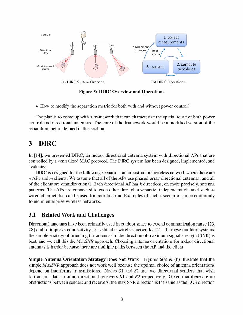
Simple Antenna Orientation Strategy Does Not Work Figures 6(a) & (b) illustrate that thesimple MaxSNR approach does not work well because the optimal choice of antenna orientationsdepend on interfering transmissions. Nodes S1 and S2 are two directional senders that wishto transmit data to omni-directional receivers R1 and R2 respectively. Given that there are noobstructions between senders and receivers, the max SNR direction is the same as the LOS direction
8
S1
S2
R1
R2
(a) Using max SNR/LOS directions
S1
S2
R1
R2
(b) Exploiting reflected paths
Figure 6: Example of exploiting multiple paths using directional antennas
(Figure 6(a)). Unfortunately, the LOS/max SNR directions lead to high interference at the receivers.In this configuration, the MAC protocol must ensure that the two senders never transmit at the sametime. In contrast, if the two senders select the orientations shown in Figure 6(b), then both senderscould transmit simultaneously. Interference would still exist at the receivers, but it would be weaker,leading to a higher SINR at R1 and R2, and potentially successful packet receptions.
Figure 3 shows the network capacity from the two algorithms, i.e., MaxCAP and MaxSNR. Herewe focus on dir-tx,omn-rx case. In this case, MaxCAP outperforms MaxSNR by 27% and 34% in thetwo scenarios. We also did some measurements in [14], which shows more significant improvementin two other indoor testbeds.
Enormous Search Space The greatest drawback of the MaxCAP approach is that it requiresexploration of all possible orientations of every sender. The size of this search space growsexponentially when potential interferers are also directional. Assuming that all n directional sendersin the network can choose any of k directions, the search space to identify the optimal orientationfor each one of the senders to their respective receivers is kn. As directional antenna technologyimproves, beam widths are likely to become smaller [1], thus increasing k. This will render a bruteforce approach even more impractical.
Directional MAC Protocol Choosing the correct MAC protocol is crucial to realizing the per-formance benefits described above. The most important task of any MAC protocol is to identifythe set of non-interfering transmissions in an area and to coordinate the activities of the varioussenders. As we discussed above, the notion of non-interfering transmissions depends on the antennaorientations of the senders. Thus, an indoor directional MAC protocol must not only identify the setof possible concurrent transmissions but also determine their orientations.
One possible choice for a MAC protocol is to use CSMA like in 802.11. However, as earlierresearch point out, while CSMA works well in networks with omni-directional transmitters, it hasseveral problems in networks with directional transmissions and performs poorly. Past research hasproposed a wide range of MAC protocols for directional wireless networks [11, 6, 12, 35, 5, 24, 37,3]. Much of this work uses RTS/CTS, and directional virtual carrier sensing (DVCS) or directionalnetwork allocation vector (DNAV). The basic idea of these solutions is that a direction will bereserved if RTS or CTS is received from that direction, and that direction is marked as unusableduring the DVCS/DNAV. One way in which these designs fail to meet our needs is that they assume
9
that the antenna orientation for any sender-receiver pair is fixed (it is a function only of the receiver).This is a reasonable assumption for outdoor settings, where there is a single reasonable orientation(the LOS direction) for any transmission. Another weakness of past MAC designs is that theylargely ignore packet capture, i.e., CSMA, DNAV and DVCA approaches tend to be too conservativein scheduling transmissions. Although this observation is not specific to directional networks orindoor environments, we found that taking advantage of capture can significantly improve spatialreuse.
3.2 Design OverviewThe core of DIRC’s design is to use the SINR model to reduce the number of measurements neededto orient the antennas. In DIRC, only n∗ k measurements are necessary to implement a heuristicsof the MaxCAP algorithm, which is the same number of measurements needed to implement theMaxSNR algorithm.
Our design of DIRC is based on a central controller that leverages the wired network infrastruc-ture to coordinate the access points (Figure 5(a)). DIRC uses a TDMA based centralized MACprotocol, and in order to prevent the interference from omnidirectional transmissions, each timeslotis split into two phases, dirc-tx phase where only directional APs can transmit, and omni-tx phasewhere omnidirectional clients can initiate transmissions. In dirc-tx phase, the centralized controllercomputes a schedule for the directional APs; while in omni-tx phase, the default CSMA MAC isused to coordinate the omnidirectional transmitters. As shown in Figure 5(b), DIRC operates inthree stages, 1) collecting measurement, 2) scheduling, and 3) transmitting. The measurements needto be updated on two conditions, 1) the measurements need to be updated periodically, and 2) whenthe environment changes dramatically.
In the measurement stage, the centralized controller instructs each AP to send a number offrames in each direction, and all receivers would record the signal strength from that AP with aparticular direction. During this stage, the set of measurements collected is the full table of S(i, j,k)where i is the AP, j is the client, and k is the direction on the AP.
In the scheduling stage, the centralized controller would apply the SINR model on the collectedmeasurements to determine which APs can transmit and the best antenna orientations for thoseAPs. In DIRC, the centralized controller keeps a FIFO queue of backlogged transmissions, andthen try to include as many transmissions to the next timeslot as possible. For each combination ofantenna orientations, the controllers computes the SINR value for each transmission link and infersthe link throughput achieved by that link, then it computes the network capacity as the sum of alllink throughputs. Finally, it picks the best combination of antenna orientations and use that as theschedule for the next timeslot.
In the transmitting stage, the backlogged APs would inform the controller that they have framesto be transmitted to particular clients. Then the controller computes the schedule for the nexttimeslot and send the schedules to the APs. Then in dirc-tx phase, APs would set their directionsand send frames to the clients. In omni-tx phase, the clients can send link-layer ACKs and dataframes to the APs.
10
0
10
20
30
40
50
60
70
80
OMNICSMA
Max SNRCSMA
Max SNRTDMA
DIRC
Ne
two
rk C
ap
acity (
Mb
ps)
Direction Selection / MAC
MeanMedian
(a) UDP Performance
0
10
20
30
40
50
60
70
80
Mean Median
Ne
two
rk C
ap
acity (
Mb
ps)
����
OMNI/CSMAScheduling(+)
DIRC(+)Timeslot Split(-)
Scan(-)
(b) Overhead and gain for UDP
0
10
20
30
40
50
60
70
80
OMNICSMA
Max SNRCSMA
Max SNRTDMA
DIRC
Ne
two
rk C
ap
acity (
Mb
ps)
Direction Selection / MAC
MeanMedian
(c) TCP Performance
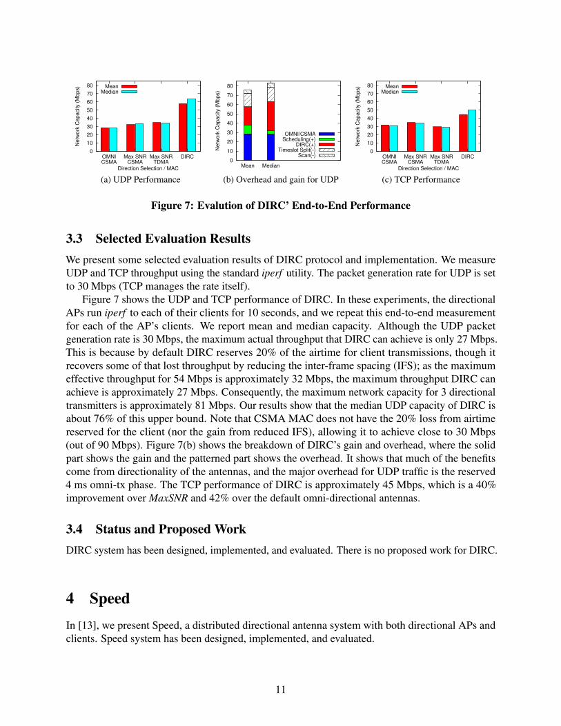
Figure 7: Evalution of DIRC’ End-to-End Performance
3.3 Selected Evaluation ResultsWe present some selected evaluation results of DIRC protocol and implementation. We measureUDP and TCP throughput using the standard iperf utility. The packet generation rate for UDP is setto 30 Mbps (TCP manages the rate itself).
Figure 7 shows the UDP and TCP performance of DIRC. In these experiments, the directionalAPs run iperf to each of their clients for 10 seconds, and we repeat this end-to-end measurementfor each of the AP’s clients. We report mean and median capacity. Although the UDP packetgeneration rate is 30 Mbps, the maximum actual throughput that DIRC can achieve is only 27 Mbps.This is because by default DIRC reserves 20% of the airtime for client transmissions, though itrecovers some of that lost throughput by reducing the inter-frame spacing (IFS); as the maximumeffective throughput for 54 Mbps is approximately 32 Mbps, the maximum throughput DIRC canachieve is approximately 27 Mbps. Consequently, the maximum network capacity for 3 directionaltransmitters is approximately 81 Mbps. Our results show that the median UDP capacity of DIRC isabout 76% of this upper bound. Note that CSMA MAC does not have the 20% loss from airtimereserved for the client (nor the gain from reduced IFS), allowing it to achieve close to 30 Mbps(out of 90 Mbps). Figure 7(b) shows the breakdown of DIRC’s gain and overhead, where the solidpart shows the gain and the patterned part shows the overhead. It shows that much of the benefitscome from directionality of the antennas, and the major overhead for UDP traffic is the reserved4 ms omni-tx phase. The TCP performance of DIRC is approximately 45 Mbps, which is a 40%improvement over MaxSNR and 42% over the default omni-directional antennas.
3.4 Status and Proposed WorkDIRC system has been designed, implemented, and evaluated. There is no proposed work for DIRC.
4 SpeedIn [13], we present Speed, a distributed directional antenna system with both directional APs andclients. Speed system has been designed, implemented, and evaluated.
11
0 10 20 30 40 50 60 70 80
Campus Lab
Net
wor
k C
apac
ity (
Mbp
s)Location
SpeedDIRCOMNI
(a) UDP
0 10 20 30 40 50 60 70 80
Campus Lab
Net
wor
k C
apac
ity (
Mbp
s)
Location
OMNIdir-tx(+)
multiradio(+)rate adapt(+)
Speedrts(-)
measurement(-)
(b) UDP Breakdown
0 10 20 30 40 50 60 70 80
Campus Lab
Net
wor
k C
apac
ity (
Mbp
s)
Location
SpeedDIRCOMNI
(c) TCP
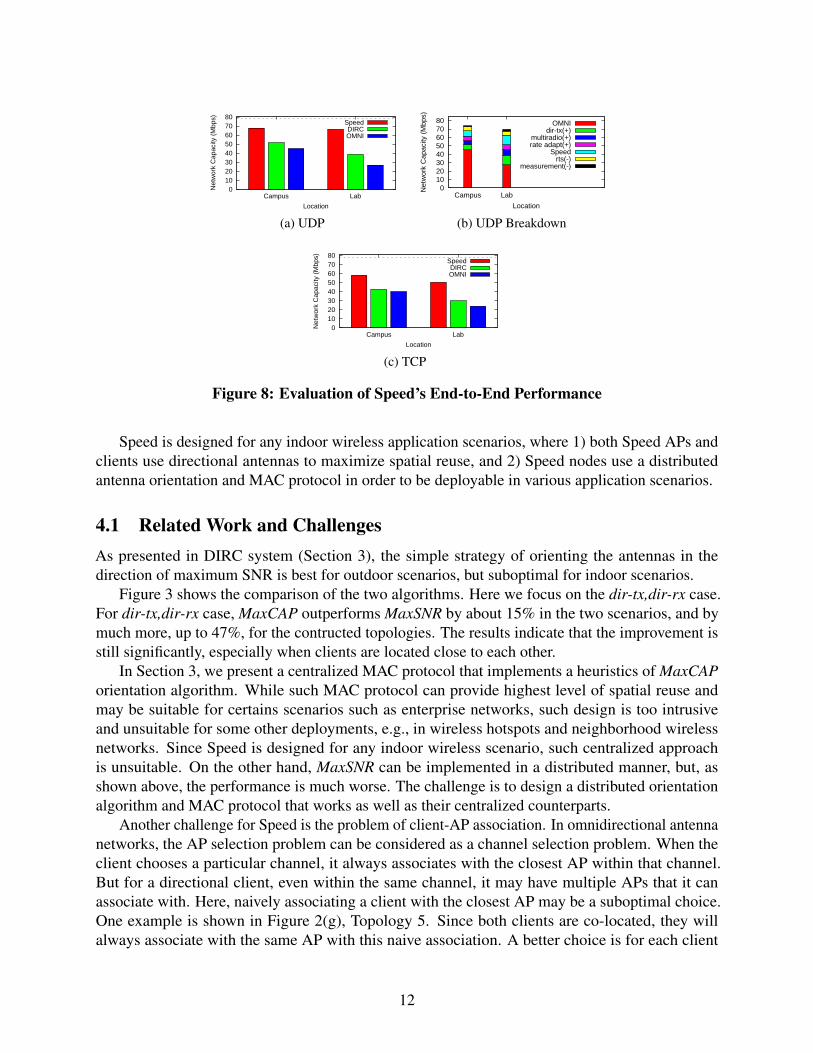
Figure 8: Evaluation of Speed’s End-to-End Performance
Speed is designed for any indoor wireless application scenarios, where 1) both Speed APs andclients use directional antennas to maximize spatial reuse, and 2) Speed nodes use a distributedantenna orientation and MAC protocol in order to be deployable in various application scenarios.
4.1 Related Work and ChallengesAs presented in DIRC system (Section 3), the simple strategy of orienting the antennas in thedirection of maximum SNR is best for outdoor scenarios, but suboptimal for indoor scenarios.
Figure 3 shows the comparison of the two algorithms. Here we focus on the dir-tx,dir-rx case.For dir-tx,dir-rx case, MaxCAP outperforms MaxSNR by about 15% in the two scenarios, and bymuch more, up to 47%, for the contructed topologies. The results indicate that the improvement isstill significantly, especially when clients are located close to each other.
In Section 3, we present a centralized MAC protocol that implements a heuristics of MaxCAPorientation algorithm. While such MAC protocol can provide highest level of spatial reuse andmay be suitable for certains scenarios such as enterprise networks, such design is too intrusiveand unsuitable for some other deployments, e.g., in wireless hotspots and neighborhood wirelessnetworks. Since Speed is designed for any indoor wireless scenario, such centralized approachis unsuitable. On the other hand, MaxSNR can be implemented in a distributed manner, but, asshown above, the performance is much worse. The challenge is to design a distributed orientationalgorithm and MAC protocol that works as well as their centralized counterparts.
Another challenge for Speed is the problem of client-AP association. In omnidirectional antennanetworks, the AP selection problem can be considered as a channel selection problem. When theclient chooses a particular channel, it always associates with the closest AP within that channel.But for a directional client, even within the same channel, it may have multiple APs that it canassociate with. Here, naively associating a client with the closest AP may be a suboptimal choice.One example is shown in Figure 2(g), Topology 5. Since both clients are co-located, they willalways associate with the same AP with this naive association. A better choice is for each client
12
0
20
40
60
80
100
20 40 60 80 100 120 140Per
cent
age
of C
over
age
(%)
Beamwidth
1 sector2 sector4 sector8 sector
16 sector
(a) Indoor
0
20
40
60
80
100
20 40 60 80 100 120 140Per
cent
age
of C
over
age
(%)
Beamwidth
1 sector2 sector4 sector8 sector
16 sector
(b) Outdoor
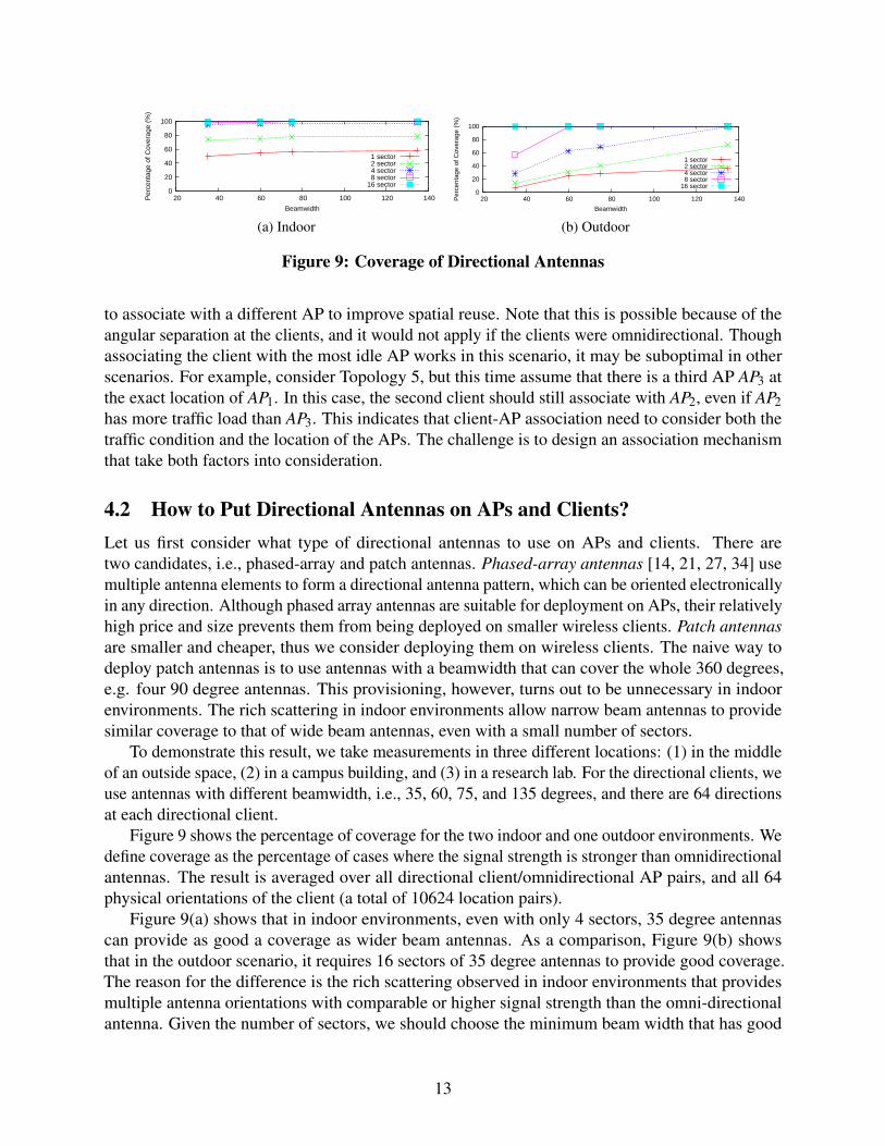
Figure 9: Coverage of Directional Antennas
to associate with a different AP to improve spatial reuse. Note that this is possible because of theangular separation at the clients, and it would not apply if the clients were omnidirectional. Thoughassociating the client with the most idle AP works in this scenario, it may be suboptimal in otherscenarios. For example, consider Topology 5, but this time assume that there is a third AP AP3 atthe exact location of AP1. In this case, the second client should still associate with AP2, even if AP2has more traffic load than AP3. This indicates that client-AP association need to consider both thetraffic condition and the location of the APs. The challenge is to design an association mechanismthat take both factors into consideration.
4.2 How to Put Directional Antennas on APs and Clients?Let us first consider what type of directional antennas to use on APs and clients. There aretwo candidates, i.e., phased-array and patch antennas. Phased-array antennas [14, 21, 27, 34] usemultiple antenna elements to form a directional antenna pattern, which can be oriented electronicallyin any direction. Although phased array antennas are suitable for deployment on APs, their relativelyhigh price and size prevents them from being deployed on smaller wireless clients. Patch antennasare smaller and cheaper, thus we consider deploying them on wireless clients. The naive way todeploy patch antennas is to use antennas with a beamwidth that can cover the whole 360 degrees,e.g. four 90 degree antennas. This provisioning, however, turns out to be unnecessary in indoorenvironments. The rich scattering in indoor environments allow narrow beam antennas to providesimilar coverage to that of wide beam antennas, even with a small number of sectors.
To demonstrate this result, we take measurements in three different locations: (1) in the middleof an outside space, (2) in a campus building, and (3) in a research lab. For the directional clients, weuse antennas with different beamwidth, i.e., 35, 60, 75, and 135 degrees, and there are 64 directionsat each directional client.
Figure 9 shows the percentage of coverage for the two indoor and one outdoor environments. Wedefine coverage as the percentage of cases where the signal strength is stronger than omnidirectionalantennas. The result is averaged over all directional client/omnidirectional AP pairs, and all 64physical orientations of the client (a total of 10624 location pairs).
Figure 9(a) shows that in indoor environments, even with only 4 sectors, 35 degree antennascan provide as good a coverage as wider beam antennas. As a comparison, Figure 9(b) showsthat in the outdoor scenario, it requires 16 sectors of 35 degree antennas to provide good coverage.The reason for the difference is the rich scattering observed in indoor environments that providesmultiple antenna orientations with comparable or higher signal strength than the omni-directionalantenna. Given the number of sectors, we should choose the minimum beam width that has good
13
coverage (e.g., for four sectors, 35 degree antennas should be used) since this offers the strongerangular separation.
Thus, we propose that directional clients that are primarily used in indoor environments shouldbe equipped with a small number of narrow beam antennas: 35 or 65 degree patch antennas, alongwith an omnidirectional antenna to handle the scenario where none of the directional sectors canprovide strong signal strength. Since APs do not have a strict size constraint, APs can use eithersectorized patch antennas or phased-array antennas.
4.3 Design OverviewThe MAC protocol in Speed is based on timeslots and timeslot reservations. During each timeslot,non-interfering data traffic from multiple APs will transmit at the same time, regardless of thecarrier sensing, to achieve spatial reuse. Other traffic, such as uplink traffic from clients to APs,traffic from other non-protocol compliant transmissions, and all management frames, may also betransmitted anytime, but these frames rely on CSMA mechanism to avoid collisions.
To manage the tradeoff between the MaxSNR and the MaxCAP algorithms, Speed uses a newdistributed algorithm which is a compromise between the MaxSNR and the MaxCAP approaches.Unlike MaxSNR, Speed does consider other transmissions in the network to determine antennaorientations; and unlike MaxCAP, it does not rely on exhaustive search and can be implementeddistributedly. The idea of Speed’s algorithm is for each AP to choose its antenna orientationdepending on existing reservations of the timeslot, i.e., the APs can reserve the timeslot withcertain antenna orientations if the new reservation of the timeslot do not interfere with any existingreservations on the same timeslot.
When sending data frames, Speed takes the approach presented in [7, 32], to allow clients tosend data packets to the APs (e.g., TCP ACKs), and to allow the existence of other non-protocolcompliant transmissions. In Speed, APs disable random backoff but keep carrier sensing, for dataframes. All management frames are sent to a separate hardware txqueue where default CSMA isused.
In Speed, directional clients determine which AP to associate with. We assume that clients havealready chosen the channel it operates in. To simplify presentation, we ignore AP backbone capacity,which is also an important metric in AP selection [22, 33] and assume that the wireless link is thebottleneck. To determine association, the idea is to let the client predict the link throughput if theclient is going to associate with a given AP. The predicted throughput is based on the conflict graphand the traffic load on each AP. In Speed, this prediction involves two pieces of information: 1) thenumber of timeslots that can be allocated to the client; and 2) the expected link throughput for eachtimeslot. Then the predicted link throughput is the product of the two. This requires traffic loadinformation, which the APs include in their beacon messages. The load information includes thenumber of timeslots allocated to each client that associates with that AP, and the number of idletimeslots on that AP.
4.4 Selected Evaluation ResultsWe evaluate both the UDP and TCP performance of Speed in the campus and the lab scenarios(Figures 2(a) and (b)). We placed six clients C1 to C6 as indicated on the map, and placed three
14
directional APs in various locations. For each AP location, we activate all possible client combina-tions, and present the mean capacity from all combinations. For each setup, the experiment runs for1 minute, and the results are averaged over 3 runs. Figure 8 shows the UDP and TCP performancefor Speed, DIRC [14], and OMNI (omnidirectional APs and clients). The results show that in thelab senario, Speed improves UDP performance over DIRC by 100% and over OMNI by 127%, andSpeed improves TCP performance over DIRC by 56% and over OMNI by 93%. In campus scenario,Speed improves UDP performance over DIRC by 31% and over OMNI by 50%, and improves TCPperformance over DIRC by 36% and over OMNI by 45%. The reason that the improvement in thelab scenario is much higher than that in the campus scenario is that the distance separation in thecampus scenario is higher, thus the performance of DIRC and OMNI in the campus scenario ismuch better.
Figure 8 shows the breakdown of gains and losses for UDP performance for the lab scenario.Compared to the performance of omnidirectional transmissions, the gain of Speed primarily comesfrom directionality on APs (42%) and additional directionality on clients (85%). But at the sametime, the gain will be lower if there is no data rate adaptation (11%), or there is only one radioon each directional client (9%). The overhead of Speed includes reservation traffic (8%) andmeasurement updates (3%).
4.5 Status and Proposed WorkSpeed system has been designed, implemented, and evaluated. However, there are still questionsregarding the directional antenna placement on APs. First, there is a question of what type ofdirectional antennas should be deployed on APs. We show in Section 4.2 that both phased-array andpatch antennas can be used on APs, but the two technologies still differ in certain ways. For example,phased array antennas are more expensive, but they can change beamwidth and can orient to anydesired direction. Such capability may be useful in multicast applications and during dynamic events.Thus a better understanding of dynamics and beamwidth is necessary to determine which type ofdirectional antennas should be deployed in practice. Second, the problem is further complicated inSpeed since Speed clients are equipped with a small number of narrow beams antennas. We onlyshow that when the APs are omnidirectional (or similarly when APs have phased-array antennasthat can steer to any particular direction), a small number of narrow beam antennas can provide asgood coverage as wide beam antennas. However, it is unclear if that still holds when the APs alsouse a small number of narrow beam antennas.
5 Power ControlIn this section, we present a power control protocol for dense wireless networks. This protocol isdesigned for existing omnidirectional antenna networks that do not require deploying additionalhardware. The power control algorithm has been designed, and we plan to design its MAC protocol,implement the protocol, and evaluate it.
15
L11 L22
L21L12
S1
R1
S2
R2
Lcca
S1 R2S2
F22
R1
F11
(b) Diversified AP-client distance across cells(R2 is closer to S2 than R1 to S1)
0
50
100
150
default802.11
txpower only[1]
txpower onlyfix asymm.[23]
CCA only[28]
joint tuningour proto
Thp
ove
r ba
selin
e (%
)
Txpower and/or CCA tuning
F11 ThpF22 Thp
Capacity
S1 R4S2
F24R1
F11
R2
F12 R3
F13
(d) Diversified interference level within a cell(R3 experience more interference than R1,R2)
0
50
100
150
200
default802.11
per-cell[15]
per-linksame CCA[11]
per-linkour proto
Thp
ove
r ba
selin
e (%
)
Tuning Granularity
F11 ThpF12 ThpF13 ThpF24 Thp
Capacity
(a) (c) Evaluation of (b) (e) Evaluation of (d)
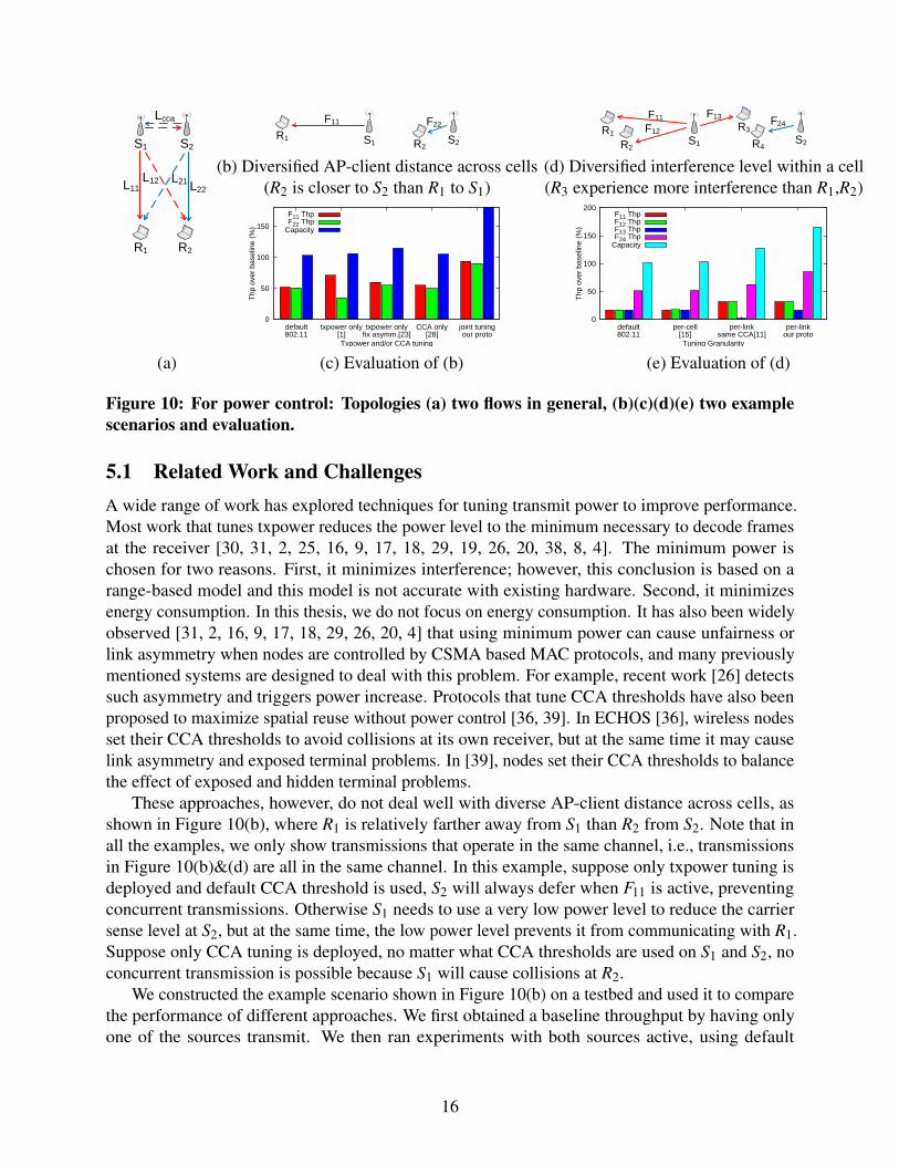
Figure 10: For power control: Topologies (a) two flows in general, (b)(c)(d)(e) two examplescenarios and evaluation.
5.1 Related Work and ChallengesA wide range of work has explored techniques for tuning transmit power to improve performance.Most work that tunes txpower reduces the power level to the minimum necessary to decode framesat the receiver [30, 31, 2, 25, 16, 9, 17, 18, 29, 19, 26, 20, 38, 8, 4]. The minimum power ischosen for two reasons. First, it minimizes interference; however, this conclusion is based on arange-based model and this model is not accurate with existing hardware. Second, it minimizesenergy consumption. In this thesis, we do not focus on energy consumption. It has also been widelyobserved [31, 2, 16, 9, 17, 18, 29, 26, 20, 4] that using minimum power can cause unfairness orlink asymmetry when nodes are controlled by CSMA based MAC protocols, and many previouslymentioned systems are designed to deal with this problem. For example, recent work [26] detectssuch asymmetry and triggers power increase. Protocols that tune CCA thresholds have also beenproposed to maximize spatial reuse without power control [36, 39]. In ECHOS [36], wireless nodesset their CCA thresholds to avoid collisions at its own receiver, but at the same time it may causelink asymmetry and exposed terminal problems. In [39], nodes set their CCA thresholds to balancethe effect of exposed and hidden terminal problems.
These approaches, however, do not deal well with diverse AP-client distance across cells, asshown in Figure 10(b), where R1 is relatively farther away from S1 than R2 from S2. Note that inall the examples, we only show transmissions that operate in the same channel, i.e., transmissionsin Figure 10(b)&(d) are all in the same channel. In this example, suppose only txpower tuning isdeployed and default CCA threshold is used, S2 will always defer when F11 is active, preventingconcurrent transmissions. Otherwise S1 needs to use a very low power level to reduce the carriersense level at S2, but at the same time, the low power level prevents it from communicating with R1.Suppose only CCA tuning is deployed, no matter what CCA thresholds are used on S1 and S2, noconcurrent transmission is possible because S1 will cause collisions at R2.
We constructed the example scenario shown in Figure 10(b) on a testbed and used it to comparethe performance of different approaches. We first obtained a baseline throughput by having onlyone of the sources transmit. We then ran experiments with both sources active, using default
16
configuration, txpower tuning only (minimum power), txpower tuning only with link asymmetryfixed by power increase ([26]), CCA tuning only (ECHOS [36] with link asymmetry fixed), and theperformance that can be achieved. The results, as a percentage of baseline, are shown in Figure 10(c).We see that tuning txpower only (minimum power) suffers from slight link asymmetry, which canbe fixed by increasing the power on F22. The capacity for both txpower tuning only and CCA tuningonly are similar to that of default, i.e. 100% and no spatial reuse. Hoever, it is possible to enableconcurrent transmissions in this scenario, increasing capacity to 185%.
Systems that jointly tune power levels and CCA thresholds have also been proposed [10, 15],but they tune at a coarse granularity. For example, [10] assigns the same CCA threshold to everynode in the network, and [15] uses the same power/CCA configuration for all the nodes in the samecell. In [19], the authors conclude that coarse-grained approaches are asymptotically optimal, butspatial reuse can still be greatly limited by the “worst” client when the interference level within acell is diverse.
One example of this limitation is shown in Figure 10(d). In the example, receiver R3 is in a badlocation since flow F13 interferes with F24, but otherwise all flows can transmit simultaneously. Inthis example, concurrent transmissions can only happen without incurring starvation by a per-linkprotocol, because 1) without per-link txpower, as in [15], the same power level will be used onF11,F12,F13, which imposes the same carrier sensing level on S2, making S2 unable to distinguishthe three transmissions. S2, in this case, can either use a high CCA that causes R3 to starve, or it canuse a low CCA that wastes the spatial reuse opportunities with F11,F12. 2) without per-link CCA, asin [10], S1 can either use a high CCA that let F13 and F24 interfere with each other, causing F13 tostarve, or it can use a low CCA which again wastes the spatial reuse opportunities. This exampleillustrutes that the performance of coarse-grained protocols is limited by the “worst” client.
We constructed this example scenario on our testbed, using the same setup as presented above.In this experiment, we ran the joint txpower and CCA tuning protocol on a per-cell [15], on aper-link basis with a fixed CCA threshold for all nodes [10], and the performance can be achieved.The results are shown in Figure 10(e) The per-cell approach prevents concurrent transmissions,i.e. capacity is around 100%. While the per-link approach with fixed CCA yields higher capacity(125%), one link F13 suffers from starvation. Lowering the fixed CCA threshold on both sendersfixes the link asymmetry, but the capacity is then almost the same as that of the per-cell approach.In fact, all concurrent transmissions can be enabled in this scenario, yielding a capacity of 164%.
To gain insight into choosing the right power levels, we first consider a two-flow scenario. InFigure 10(a) S1 transmits to R1 and S2 transmits to R2. We use Li j to denote the path loss from Si toR j (i, j ∈ {1,2}), and Pi to denote the transmit power level from Si to Ri. Thus the SINR at receiversR1 and R2 are SINR1 = P1−L11−P2 + L21 and SINR2 = P2−L22−P1 + L12, respectively. Notethat independent of the transmit power levels, we have SINR1 + SINR2 = L12 + L21−L11−L22.Power control essentially allocates this sum between the two transmissions, i.e. increasing SINR1will decrease SINR2. In order to enable concurrent transmission, we need both SINR1 ≥ SINRthrshand SINR2 ≥ SINRthrsh. Note that it may not be possible to satisfy the SINR constraints, indicatingthat concurrent transmissions are impossible. If there are multiple links, however, the choice madefor one link may not be compatible with the choices for other links. In fact, finding the optimalconfiguration is conditional NP-hard, thus the running time to find the optimal power levels is O(nk),where n is the number of APs, and k is the number of power levels on each node.
17
5.2 Design OverviewThe core of the power tuning algorithm is a greedy heuristic that iteratively tunes power levels toallow more concurrent transmissions by removing edges from the conflict graph. In each iteration,and for each link, the algorithm examines the power levels used on all other links and the topologyto determine what power level would allow simultaneous transmission with the other links. It thenpicks the power level that allows the most concurrency. The new power level will be used if it allowsmore concurrent transmissions than that in the previous iteration. Note that after each iteration,the number of edges in the conflict graph decreases, and the algorithm converges when no moreedges can be removed from the conflict graph. Also, by using this algorithm, the source that needsmaximum power level will hit the power limit, and then all other sources will keep an appropriateratio to that source.
5.3 Preliminary EvaluationIn Figure 10, we evaluated an earlier version of the power control protocol. Figure 10(c)&(e)shows the link throughputs and network capacity of our earlier protocol in the two scenarios ofFigure 10(b)&(d). The results show that our earlier protocol can outperform existing solutions, andwe expect our new system to perform even better.
5.4 Status and Proposed WorkThe iterative power control algorithm has been designed, and we propose 1) to design the MACprotocol, and 2) to implement and evaluate the system. The MAC protocol for power control wouldbe based on the MAC protocol presented for Speed in Section 4, where Speed’s MAC protocolneeds to be adapted to support the iterative power control algorithm. For example, the iterativealgorithm needs the set of active transmissions to determine the appropriate power level on eachwireless node, and there is the question of how to determine the set of active transmissions. Timeslotreservations only provide partial information because potential senders may not be able to accessthe channel.
6 TimelineWe propose the following timeline to finish the thesis:
• Apr. - Jun. 2010: Finish evaluating the effects of dynamics and beamwith on performance,and the framework to characterize spatial reuse (Section 2.4)
• Jun. - Jul. 2010: Finish evaluating different antenna configurations on APs (Section 4.5)• Jul. - Jan. 2011: Finish the power control protocol (Section 5.4)• Feb. - May 2011: Tie up loose ends, write thesis
References[1] SiBEAM: Wireless Beyond Boundaries (www.sibeam.com).
18
[2] A. Akella, G. Judd, S. Seshan, and P. Steenkiste. Self management in chaotic wirelessdeployments. In MobiCom, 2005.
[3] L. Bao and J. J. Garcia-Luna-Aceves. Receiver-oriented multiple access in ad hoc networkswith directional antennas. Wirel. Netw., 11(1-2), 2005.
[4] Y.-J. Choi and K. Shin. Power-adjusted random access to a wireless channel. INFOCOM,2008.
[5] R. R. Choudhury and N. H. Vaidya. Deafness: A MAC problem in ad hoc networks whenusing directional antennas. ICNP, 2004.
[6] R. R. Choudhury, X. Yang, R. Ramanathan, and N. H. Vaidya. Using directional antennas formedium access control in ad hoc networks. In MobiCom, 2002.
[7] K. Jamieson, B. Hull, A. Miu, and H. Balakrishnan. Understanding the real-world performanceof carrier sense. In E-WIND, 2005.
[8] L. Jia, X. Liu, G. Noubir, and R. Rajaraman. Transmission power control for ad hoc wirelessnetworks: throughput, energy and fairness. WCNC, 2005.
[9] E. Jung and N. Vaidya. A power control mac protocol for ad-hoc networks. MOBICOM, 2002.
[10] T.-S. Kim, J. C. Hou, and H. Lim. Improving spatial reuse through tuning transmit power,carrier sense threshold, and data rate in multihop wireless networks. In MobiCom, 2006.
[11] Y.-B. Ko, V. Shankarkumar, and N. H. Vaidya. Medium access control protocols usingdirectional antennas in adhoc networks. In INFOCOM, 2000.
[12] T. Korakis, G. Jakllari, and L. Tassiulas. A MAC protocol for full exploitation of directionalantennas in ad-hoc wireless networks. In MobiHoc, 2003.
[13] X. Liu, A. Sheth, M. Kaminsky, K. Papagiannaki, S. Seshan, and P. Steenkiste. Pushing theenvelope of wireless indoor spatial reuse using directional access points and clients.
[14] X. Liu, A. Sheth, M. Kaminsky, K. Papagiannaki, S. Seshan, and P. Steenkiste. Dirc: increasingindoor wireless capacity using directional antennas. SIGCOMM Comput. Commun. Rev., 39(4):171–182, 2009.
[15] V. Mhatre, K. Papagiannaki, and F. Baccelli. Interference mitigation through power control inhigh density 802.11 wlans. In Infocom, 2007.
[16] J. Monks, V. Bharghavan, and W.-M. Hwu. A power controlled multiple access protocol forwireless packet networks. INFOCOM, 2001.
[17] A. Muqattash and M. Krunz. Power controlled dual channel (pcdc) medium access protocolfor wireless ad hoc networks. INFOCOM, 2003.
[18] A. Muqattash and M. Krunz. A single-channel solution for transmission power control inwireless ad hoc networks. In MobiHoc, 2004.
19
[19] S. Narayanaswamy, V. Kawadia, R. S. Sreenivas, and P. R. Kumar. Power control in ad-hocnetworks: Theory, architecture, algorithm and implementation of the compow protocol. In inEuropean Wireless Conference, 2002.
[20] V. Navda, R. Kokku, S. Ganguly, and S. Das. Slotted symmetric power control in managedwlans. Technical report, NEC Laboratories America.
[21] V. Navda, A. P. Subramanian, K. Dhanasekaran, A. Timm-Giel, and S. Das. MobiSteer: usingsteerable beam directional antenna for vehicular network access. In MobiSys, 2007.
[22] J. Pang, B. Greenstein, D. McCoy, M. Kaminsky, and S. Seshan. Wifi-reports: Improvingwireless network selection with collaboration. In MobiSys, 2009.
[23] R. K. Patra, S. Nedevschi, S. Surana, A. Sheth, L. Subramanian, and E. A. Brewer. WiLDNet:Design and implementation of high performance WiFi based long distance networks. In NSDI,2007.
[24] A. Prabhu and S. Das. Addressing deafness and hidden terninal problem in directional antennabased wireless multi-hop networks. COMSWARE, Jan. 2007.
[25] D. Qiao, S. Choi, A. Jain, and K. G. Shin. Miser: an optimal low-energy transmission strategyfor ieee 802.11a/h. In MobiCom, 2003.
[26] K. Ramachandran, R. Kokku, H. Zhang, and M. Gruteser. Symphony: synchronous two-phaserate and power control in 802.11 wlans. In MobiSys, 2008.
[27] K. Ramachandran, R. Kokku, K. Sundaresan, M. Gruteser, and S. Rangarajan. R2d2: regulatingbeam shape and rate as directionality meets diversity. In MobiSys ’09: Proceedings of the 7thinternational conference on Mobile systems, applications, and services, pages 235–248. ACM,2009.
[28] B. Raman and K. Chebrolu. Design and evaluation of a new MAC protocol for long-distance802.11 mesh networks. In MobiCom, 2005.
[29] V. Shah and S. Krishnamurthy. Handling asymmetry in power heterogeneous ad hoc networks:A cross layer approach. In ICDCS, 2005.
[30] A. Sheth and R. Han. Adaptive power control and selective radio activation for low-powerinfrastructure-mode 802.11 lans. In ICDCSW, 2003.
[31] A. Sheth and R. Han. Shush: reactive transmit power control for wireless mac protocols.WICON, July 2005.
[32] V. Shrivastava, N. Ahmed, S. Rayanchu, S. Banerjee, S. Keshav, K. Papagiannaki, andA. Mishra. Centaur: realizing the full potential of centralized wlans through a hybrid datapath. In MobiCom ’09: Proceedings of the 15th annual international conference on Mobilecomputing and networking, pages 297–308, New York, NY, USA, 2009. ACM. ISBN 978-1-60558-702-8. doi: http://doi.acm.org/10.1145/1614320.1614353.
20
[33] K. Sundaresan and K. Papagiannaki. The need for cross-layer information in access pointselection algorithms. In IMC, 2006.
[34] K. Sundaresan, K. Ramachandran, and S. Rangarajan. Optimal beam scheduling for multi-casting in wireless networks. In MobiCom ’09: Proceedings of the 15th annual internationalconference on Mobile computing and networking, pages 205–216, New York, NY, USA, 2009.ACM.
[35] M. Takai, J. Martin, R. Bagrodia, and A. Ren. Directional virtual carrier sensing for directionalantennas in mobile ad hoc networks. In MobiHoc, 2002.
[36] A. Vasan, R. Ramjee, and T. Y. C. Woo. Echos - enhanced capacity 802.11 hotspots. InInfocom, 2005.
[37] Z. Zhang. DTRA: directional transmission and reception algorithms in WLANs with direc-tional antennas for QoS support. Network, IEEE, 19(3), May-June 2005.
[38] R. Zheng and R. Kravets. On-demand power management for ad hoc networks. INFOCOM,2003.
[39] Y. Zhu, Q. Zhang, Z. Niu, and J. Zhu. On optimal physical carrier sensing: Theoretical analysisand protocol design. INFOCOM, 2007.
21