Embed Size (px)
Citation preview
FORMForum 2016 1
MAXIMAL REACHABLE EFFICIENCY OF DIESEL ENGINE IN COMPLEX OPTIMIZATION AND ENGINE CONTROL STRATEGY FOR TRANSIENTS Dolecek, Vit, Bolehovsky, Ondrej, Czech Technical University in Prague – Faculty of Mechanical Engineering, Czech Republic
Summary
Downsizing and downspeeding of ICEs have been embraced by every manufacturer of vehicle powertrains and the level of downsizing has gone to extreme in some cases. This triggers the question of an optimal level of downsizing or downspeeding in terms of the highest engine efficiency. For this purpose, simulation methods coupling different level of method depth, as 1-D methods with in-house codes for engine mechanical efficiency assessment and preliminary design of boosting devices (a virtual compressor and a turbine), have been used together with optimization codes based on genetic algorithms. To assess the final operation fuel consumption, selected optimized layouts were used in a middle class vehicle and consequently run in current and upcoming drive cycles.
1 Introduction
Increase in engine brake efficiency is achieved by downsizing in the recent decade. Downsizing profits from the reduction of relative thermal and mechanical losses and enables to improve road fuel consumption due to higher load of an engine in operation. Simultaneously, engine size and mass are reduced, which is accompanied by vehicle driving resistance decrease. Downsizing may be supplemented by downspeeding, which decreases cycle frequency (speed in rpm), which positively increases time for unsteady events during combustion and gas exchange. Since downsizing utilizes higher intake pressure, the significance of a boosting system grows and mutual interaction between the engine and the boosting system must be observed.
There have already been simulation works dealing with an uneasy task of finding total optimum downsized engine, as stated in [1], [2]. Unlike in other published studies, the optimization of BSFC was done using minimal number of constraints to find the total optimum. The unconstrained optimization demonstrated no large deviations from currently achieved efficiencies, but the significant dependence of BSFC on turbocharger group efficiency. The boosting system of this engine consisted of a fictitious single stage turbocharger of a very high pressure ratio up to 6 in very large range of mass flow rates, which was considered as not realistic. Moreover, the moment of inertia and volumes of system component were too optimistic, as well For
2 FORMForum 2016
this reason, another study [3] focusing on more detailed simulation and optimization of a two-stage turbocharger group was done, thus expanding the previous work.
The aim of the current work is to further expand those aforementioned works and to compare selected optimized downsized layouts with different levels of computational complexity of the turbocharger group in standardized driving cycles, i. e. NEDC and WLTP, and assess the potential of each individually optimized downsized engine.
2 Engine Efficiency Optimization - 1-stage Turbocharger
A calibrated 1-D model of the reference diesel engine of 1.65 dm3 displacement with conservative dimensions (bore of 80 mm, stroke of 82 mm) and bmep of 25 bar in the range of 1 000 – 4 000 rpm was used as an initial prototype. During the optimization, BMEP was increased up to 35 bar, while keeping power at different speeds equal to the initial Diesel engine, thus reducing the displacement (1.65 → 1.18 dm3). The stroke was either unchanged, keeping mean piston speed without change, or it was taken as a free parameter to be optimized.
Peak pressure, piston surface temperature, turbine inlet temperature or valve temperatures and any other constraints were not limited during the thermodynamic optimization. Other novelty was a direct coupling of thermodynamic optimum results to engine design changes, reflected by engine dimensions and to mechanical loss estimation.
Turbocharger maps were created for a virtual compressor (not limited by surging or choking but using reasonable compressor efficiency dependent on compressor pressure ratio) and turbine map derived from original one by multiplier of mass flow rate which substituted the VNT. There were two optimized variants of the total two stage turbocharger group efficiency of 50% and 60%. The range between those efficiencies was proven to be realistic for advanced design of future turbochargers [3]. Mixture strength (i.e., boost pressure), compression ratio up to 18 and all currently variable engine data were optimized using genetic optimization algorithm for searching for the optimum settings of parameters.
The optimization does not call either for extreme peak pressures or extremely short combustion durations. The optimum angle duration of combustion is close to 30 deg CA (0-90%) for high speed, being shortened to approximately 20 deg CA at low speed (reference 35 deg). The position of start of combustion is not far from top dead centre. The optimum air excess decreases with increased engine speed, allowing for partial reduction of pumping losses due to turbocharger power balance.
The results of unlimited optimization constraints have shown the importance of cooling loss at reduced engine speed and the need of a long-stroke engine design, if low speed is used dominantly in engine operation. Optimum valve timing requires a moderate Miller cycle and optimum geometrical compression ratio uses standard values of 16-18, except for reduction at lowest speeds (cooling loss). The efficiency limits presented in this paper for a downsized small car four-stroke diesel engine

FORMForum 2016 3
(achieved values of 40 - 43%, optimum at 2 000 RPM as presented in Fig. 1 is close to limit of realizable efficiency without waste heat recovery systems. Otherwise, there is only limited potential for further decreasing the total optimum of BSFC, however, it can be reached by increasing turbocharger efficiency, accompanied by the reduction of pressure losses in pipe systems.
1 BSFC map for reference BMEP 25 bar (left) and downsized BMEP 35 bar
3 Engine efficiency optimization – 2-stage turbocharger group
As the initial optimization showed significant dependency on turbocharger total efficiency, following optimization was performed with a virtual two-stage turbocharger group with fixed maximum efficiency [3]. It featured realistic, but ambitious rated parameters. The optimization included pressure distribution to both stages by changing flow areas of turbines and matching of both compressor impeller diameters to turbine ones for the best turbine operation efficiency. In this way, every calculated operation point presents the best matched combination of components and processes (combustion, valve actuation, etc.).
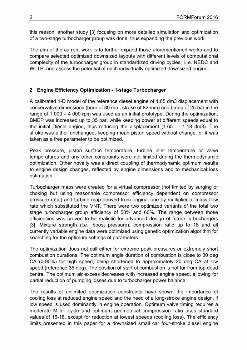
The results are slightly better if compared to a virtual single stage turbocharger but the difference is not very significant, see Fig. 2. However, the single stage turbocharger for pressure ratio of approximately 5 in a small size and very wide range of speed could not reach the assumed maximum efficiencies at all due to transonic conditions, while two-stage group can. Moreover, two-stage turbocharging enables to reach air excess suitable for efficient and emission-free combustion. The higher fictitious overall efficiency of charging group and reduced inlet manifold temperature without increasing lost work during pumping loop too much makes downsizing to BMEP over 30 bar realistic. Nevertheless, the basic issues are gain of efficiency especially close to WOT curve and the control of boost pressure, which may compromise reached optimum parameters.
4 FORMForum 2016
2 Optimized BSFC values for 1-stage and 2- stage turbocharger group
4 Driving tests of optimized engines
To assess selected engine candidates in driving conditions, NEDC and WLTP procedures were chosen, as the current and upcoming standards for vehicle emission and fuel economy tests. To capture the benefit of different levels of downsizing, all three layouts with different BMEP (25, 30 and 35 bar) in their optimum setting were run in the simulation test.
The vehicle used for tests was a lower middle class one of the mass of 1400 kg, equipped with 5 gear automatically shifted mechanical transmission. The possible changes of the car front end due to smaller engine, causing reduced mass and better drag resistance if downsized engine is used have not been taken into account yet. Turbocharger group control had to be built, so that it is able to operate in dynamic cycles. Each turbine mass flow multiplier was actuated by a PID controller according to required steady state values of compressor outlet pressure at each stage, which was an uneasy task in terms of control during dynamic cycles. Shifting pattern for NEDC was prescribed according to rules and a logic control based on criteria for shifting in WLTC was implemented in the model.
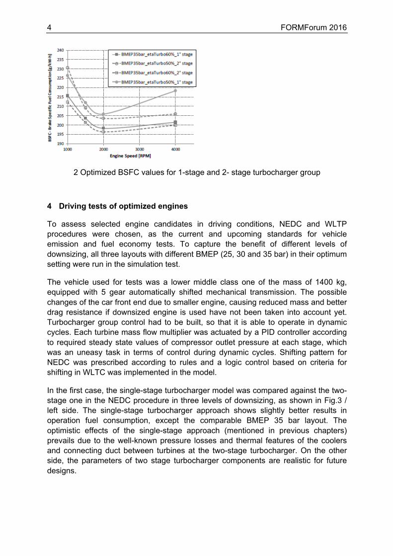
In the first case, the single-stage turbocharger model was compared against the two-stage one in the NEDC procedure in three levels of downsizing, as shown in Fig.3 / left side. The single-stage turbocharger approach shows slightly better results in operation fuel consumption, except the comparable BMEP 35 bar layout. The optimistic effects of the single-stage approach (mentioned in previous chapters) prevails due to the well-known pressure losses and thermal features of the coolers and connecting duct between turbines at the two-stage turbocharger. On the other side, the parameters of two stage turbocharger components are realistic for future designs.
FORMForum 2016 5
3 Left: NEDC: comparison between 1-stage and 2-stage turbocharger approach; Right: Comparison of NEDC and WLTC for the 2-stage layout
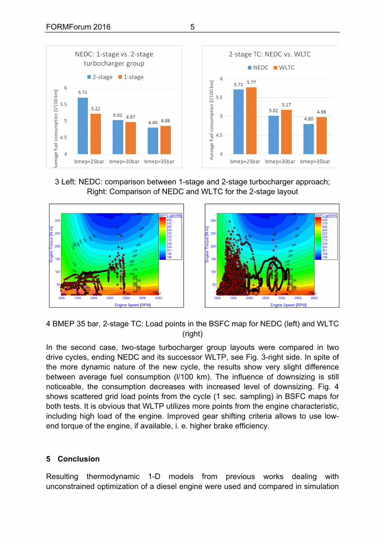
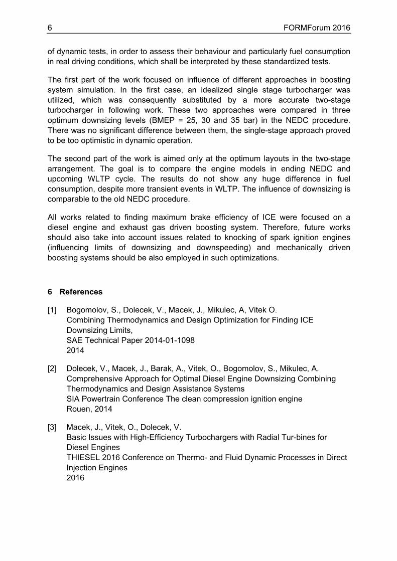
4 BMEP 35 bar, 2-stage TC: Load points in the BSFC map for NEDC (left) and WLTC (right)
In the second case, two-stage turbocharger group layouts were compared in two drive cycles, ending NEDC and its successor WLTP, see Fig. 3-right side. In spite of the more dynamic nature of the new cycle, the results show very slight difference between average fuel consumption (l/100 km). The influence of downsizing is still noticeable, the consumption decreases with increased level of downsizing. Fig. 4 shows scattered grid load points from the cycle (1 sec. sampling) in BSFC maps for both tests. It is obvious that WLTP utilizes more points from the engine characteristic, including high load of the engine. Improved gear shifting criteria allows to use low-end torque of the engine, if available, i. e. higher brake efficiency.
5 Conclusion
Resulting thermodynamic 1-D models from previous works dealing with unconstrained optimization of a diesel engine were used and compared in simulation
6 FORMForum 2016
of dynamic tests, in order to assess their behaviour and particularly fuel consumption in real driving conditions, which shall be interpreted by these standardized tests.
The first part of the work focused on influence of different approaches in boosting system simulation. In the first case, an idealized single stage turbocharger was utilized, which was consequently substituted by a more accurate two-stage turbocharger in following work. These two approaches were compared in three optimum downsizing levels (BMEP = 25, 30 and 35 bar) in the NEDC procedure. There was no significant difference between them, the single-stage approach proved to be too optimistic in dynamic operation.
The second part of the work is aimed only at the optimum layouts in the two-stage arrangement. The goal is to compare the engine models in ending NEDC and upcoming WLTP cycle. The results do not show any huge difference in fuel consumption, despite more transient events in WLTP. The influence of downsizing is comparable to the old NEDC procedure.
All works related to finding maximum brake efficiency of ICE were focused on a diesel engine and exhaust gas driven boosting system. Therefore, future works should also take into account issues related to knocking of spark ignition engines (influencing limits of downsizing and downspeeding) and mechanically driven boosting systems should be also employed in such optimizations.
6 References
[1] Bogomolov, S., Dolecek, V., Macek, J., Mikulec, A, Vitek O. Combining Thermodynamics and Design Optimization for Finding ICE Downsizing Limits, SAE Technical Paper 2014-01-1098 2014
[2] Dolecek, V., Macek, J., Barak, A., Vitek, O., Bogomolov, S., Mikulec, A. Comprehensive Approach for Optimal Diesel Engine Downsizing Combining Thermodynamics and Design Assistance Systems SIA Powertrain Conference The clean compression ignition engine Rouen, 2014
[3] Macek, J., Vitek, O., Dolecek, V. Basic Issues with High-Efficiency Turbochargers with Radial Tur-bines for Diesel Engines THIESEL 2016 Conference on Thermo- and Fluid Dynamic Processes in Direct Injection Engines 2016